

Toro 09715 Operator's Manual

FormNo.3437-560RevD
ProCore
ModelNo.09715—SerialNo.403410001andUp
ModelNo.09716—SerialNo.403410001andUp
®
864and1298Aerators
Registeratwww.T oro.com.
OriginalInstructions(EN)
*3437-560*
ThisproductcomplieswithallrelevantEuropean
directives;fordetails,pleaseseetheseparateproduct
specicDeclarationofConformity(DOC)sheet.
WARNING
CALIFORNIA
Proposition65Warning
Useofthisproductmaycauseexposure
tochemicalsknowntotheStateof
Californiatocausecancer,birthdefects,
orotherreproductiveharm.
Introduction
Thismachineisintendedtobeusedbyprofessional,
hiredoperatorsincommercialapplications.It
isdesignedprimarilyforworkinglargeareason
well-maintainedlawnsinparks,golfcourses,sports
elds,andoncommercialgrounds.Usingthisproduct
forpurposesotherthanitsintendedusecouldprove
dangeroustoyouandbystanders.
g262223
Figure1
Model09716
1.Modelandserialnumberlocation
Readthisinformationcarefullytolearnhowtooperate
andmaintainyourproductproperlyandtoavoid
injuryandproductdamage.Youareresponsiblefor
operatingtheproductproperlyandsafely .
Visitwww.Toro.comformoreinformation,including
safetytips,trainingmaterials,accessoryinformation,
helpndingadealer,ortoregisteryourproduct.
Wheneveryouneedservice,genuineToroparts,or
additionalinformation,contactanAuthorizedService
DealerorToroCustomerServiceandhavethemodel
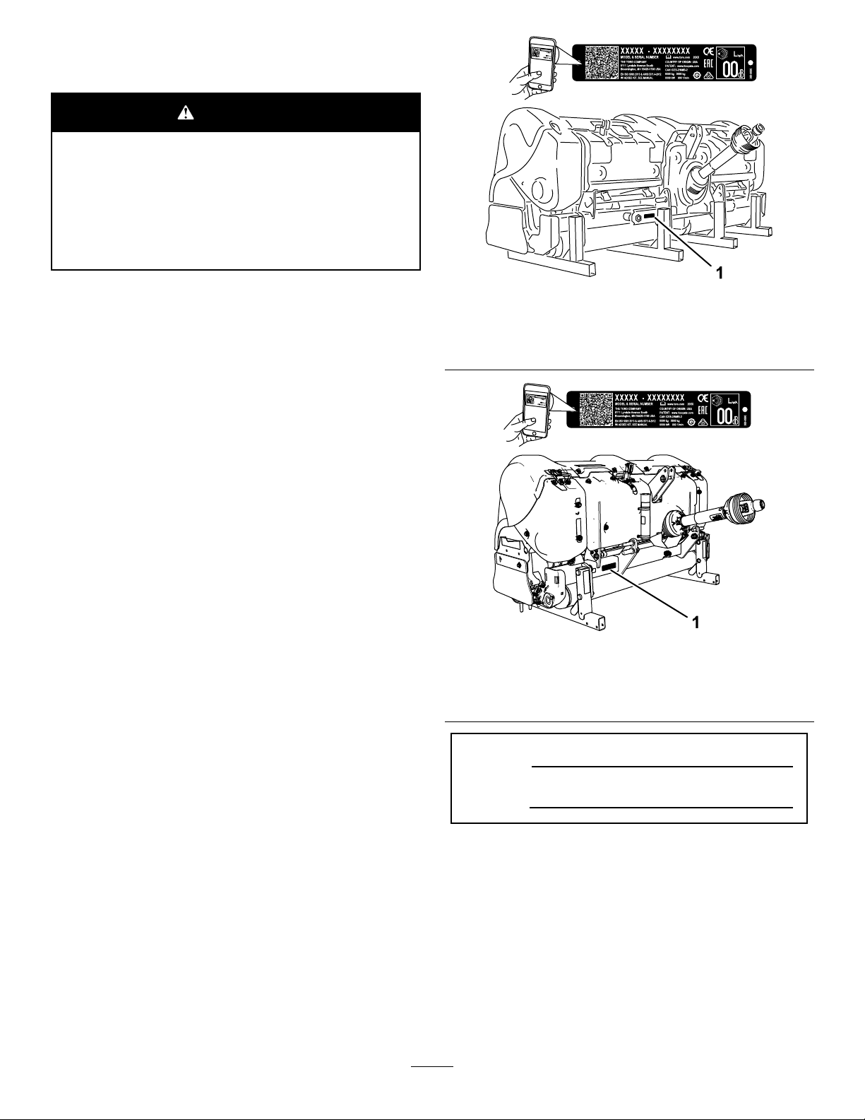
andserialnumbersofyourproductready.Figure1
andFigure2identifythelocationofthemodeland
serialnumbersontheproduct.Writethenumbersin
thespaceprovided.
Important:Withyourmobiledevice,youcan
scantheQRcodeontheserialnumberplate(if
equipped)toaccesswarranty,parts,andother
productinformation.
g262224
Figure2
Model09715
1.Modelandserialnumberlocation
ModelNo.
SerialNo.
Thismanualidentiespotentialhazardsandhas
safetymessagesidentiedbythesafetyalertsymbol
(Figure3),whichsignalsahazardthatmaycause
seriousinjuryordeathifyoudonotfollowthe
recommendedprecautions.
©2020—TheToro®Company
8111LyndaleAvenueSouth
Bloomington,MN55420
Contactusatwww.Toro.com.
2
PrintedintheUSA
AllRightsReserved

Figure3
Safety-alertsymbol
Thismanualuses2wordstohighlightinformation.
Importantcallsattentiontospecialmechanical
informationandNoteemphasizesgeneralinformation
worthyofspecialattention.
Contents
Safety.......................................................................4
GeneralSafety...................................................4
SafetyandInstructionalDecals..........................4
Setup........................................................................8
1InspectingtheMachine....................................9
2ConnectingtheLowerLinkArms......................9
3ConnectingtheUpperLink.............................10
4ConnectingthePTODriveshaft.......................11
5AdjustingtheSwayLinks...............................12
6LevelingtheMachineSide-to-Side.................13
7AdjustingtheRollerScraper...........................13
8InstallingtheTineHeadsandthe
Tines.............................................................14
9InstallingtheTurfGuards...............................14
10SecuringtheHoodLatches(CE
only)..............................................................14
11ApplyingtheEntanglementDecal.................15
12RemovingtheStorageStands.....................16
ProductOverview...................................................17
Controls...........................................................17
Specications..................................................17
Attachments/Accessories.................................17
BeforeOperation.................................................21
BeforeOperationSafety...................................21
OutcrossTractionUnitControls........................21
AdjustingtheAerationDepth............................21
UnderstandingtheTractionUnit
Controls........................................................22
UnderstandingthePrinciplesof
Operation......................................................22
PracticingtheOperatingProcedures................22
PreparingtoAerate..........................................23
DuringOperation.................................................23
DuringOperationSafety...................................23
OperatingtheMachine.....................................24
AdjustingtheHoleSpacing...............................25
AeratingHardGround.......................................26
UsingNeedleTines..........................................26
AvoidingRootZoneLifting................................26
AdjustingtheRotalinkAssembly.......................26
OperatingTips.................................................27
AfterOperation....................................................27
AfterOperationSafety......................................27
TransportingtheMachine.................................27
g000502
CleaningtheMachineafterUse........................27
Maintenance...........................................................28
RecommendedMaintenanceSchedule(s)...........28
MaintenanceSafety..........................................28
JackingtheMachine.........................................29
GreasingtheBearingsandBushings................29
CheckingtheGearboxLubrication....................30
ChangingtheGearboxLubrication...................31
CheckingtheCoringHeadFastener
Torque...........................................................31
InspectingtheBelts..........................................31
AdjustingtheBeltT ension.................................31
ReplacingtheDriveBelt...................................32
AdjustingtheSideShield..................................34
ReplacingtheTurfGuards................................34
CoringHeadTiming..........................................34
RemovingtheMachinefromtheTraction
Unit...............................................................35
Storage...................................................................36
StorageSafety..................................................36
StoringtheMachine..........................................36
3

Safety
GeneralSafety
Thisproductiscapableofamputatinghandsand
feetandofthrowingobjects.Alwaysfollowallsafety
instructionstoavoidseriouspersonalinjury.
Usingthisproductforpurposesotherthanitsintended
usecouldprovedangeroustoyouandbystanders.
•Readandunderstandthecontentsofthis
Operator’sManualbeforeusingthemachine.
•Useyourfullattentionwhileoperatingthe
machine.Donotengageinanyactivitythat
causesdistractions;otherwise,injuryorproperty
damagemayoccur.
•Donotputyourhandsorfeetnearmoving
componentsofthemachine.
SafetyandInstructionalDecals
•Donotoperatethemachinewithoutallguards
andothersafetyprotectivedevicesinplaceand
functioningproperlyonthemachine.
•Keepclearofanydischargeopening.Keep
bystandersandpetsawayfromthemachine.
•Keepbystandersandchildrenoutoftheoperating
area.Neverallowchildrentooperatethemachine.
•Alwaysshutofftheengineofthetractionunit,
removethekey(ifequipped),waitforallmoving
partstostop,andallowthemachinetocool
beforeadjusting,servicing,cleaning,orstoring
themachine.
Improperlyusingormaintainingthismachinecan
resultininjury.Toreducethepotentialforinjury,
complywiththesesafetyinstructionsandalways
payattentiontothesafety-alertsymbol
meansCaution,Warning,orDanger—personalsafety
instruction.Failuretocomplywiththeseinstructions
mayresultinpersonalinjuryordeath.
,which
Safetydecalsandinstructionsareeasilyvisibletotheoperatorandarelocatednearanyarea
ofpotentialdanger.Replaceanydecalthatisdamagedormissing.
93–6696
1.Storedenergyhazard—readtheOperator'sManual.
110-4665
decal93-6696
decal110-4665
1.ReadtheOperator'sManual.
1.Installthepostsinthe
standtotheholesinthe
frame.
4
decal110-4666
110-4666
2.Usepinstosecurethe
frametothestand.

1.Coringdepth
decal110-4668
110-4668
1.Entanglementhazard,shaft—stayawayfrommovingparts.
2.PTOspeedandinputdirection.
3.Usecliptosecurelashcablewhennotinuse.Uselash
cabletosupportthepowertake-offwhenthemachineis
decal110-4678
disconnectedfromtractor.
110-4678
decal110-4667
110-4667
1.Springlength
2.Storedenergyhazard—readtheOperator'sManual.
3.Entanglementhazard,belt—stayawayfrommovingparts.
110-4670
1.Warning—readtheOperator'sManual.
2.Warning—removethekeyandreadtheinstructions.
3.Warning—receivetrainingbeforeoperatingthemachine.7.Crushinghazardofhandandbody—supportmachineon
4.Entanglementhazard,belt—stayawayfrommovingparts.
5.Entanglementhazard,belt—keepallguardsinplace.
6.Crushinghazardofhandorfoot—keepbystandersawayfrom
themachine.
standwhennotinuse.
8.Fallinghazard—donotcarrypassengers.
decal110-4670
5

decal92-1581
92–1581
decal92-1582
92–1582
decal110-4677
110-4677
1.Turnclockwiseto
decreaseaerationdepth.
110-4664
1.ReadtheOperator's
Manual.
2.Wrenchsize4.Torque
2.Turncounterclockwiseto
increaseaerationdepth.
decal110-4664
3.Boltsize
decal106-8856
106-8856
1.ReadtheOperator'sManual.
6

133-8061
138-9038
1.Entanglementhazard—readtheOperator’sManual;stay
awayfrommovingparts;keepallguardsandshieldsin
place.
decal133-8061
decal138-9038
7

Setup
LooseParts
Usethechartbelowtoverifythatallpartshavebeenshipped.
ProcedureDescription
1
2
3
4
5
6
7
8
9
Nopartsrequired
Lynchpin2
Linkpin1
Lynchpin1
Bolt(1/2x3inches)
Nut(1/2inch)
Shortdriveshaft,PartNo.115-2839
(maybeneeded;soldseparately)
Nopartsrequired
Nopartsrequired
Nopartsrequired
Nopartsrequired
Turfguards(notincluded)
Qty.
Use
–
1
1
–
–
–
–
–
–
Inspectthemachine.
Connectthelowerlinkarms.
Connecttheupperlink.
ConnectthePTOdriveshaft.
Adjusttheswaylinks.
Levelthemachineside-to-side.
Adjusttherollerscraper.
Installthetineheadsandthetines.
Installtheturfguards.
CEComplianceKit,PartNo.1 10-4693
10
11
12
(notincluded)
CEentanglementdecal
Lynchpin(ProCore864)
Lynchpin(ProCore1298)
1
4
4
8
Securethehoodlatches(requiredfor
CEonly).
Applytheentanglementdecal—CE
mowers
Removethestoragestands.
8

1
InspectingtheMachine
NoPartsRequired
Procedure
ProCore864
Usethefollowinglistasareference:
•Usea30PTOhorsepowerminimumwhen
aeratinginlighttonormalsoilconditions(sandyto
sandy/loamsoilswithaveragecompaction).
•Usea35PTOhorsepowerminimumwhen
aeratinginnormaltoheavysoilconditions(heavy
loam,clay,androckysoilswithaboveaverage
compaction).
•ThetractionunitmusthaveacategoryIor
II3-pointhitchwithaminimumimplementlift
capacityof714kg(1,575lb).
•ThetractionunitmusthaveaPTOoutput-shaft
speedof540rpm.
•Adequatefront-endweight(ballast)tooffsetthe
weightofthemachine.
•Checkthetireairpressureofthetractionunit.
Adjustthetireairpressureasneeded.
Important:Donotexceedthemaximum
orminimumtireinationpressuresas
recommendedbytiremanufacturer.
ProCore1298
Usethefollowinglistasareference:
•Usea45PTOhorsepowerminimumwhen
aeratinginlighttonormalsoilconditions(sandyto
sandy/loamsoilswithaveragecompaction).
•50PTOhorsepowerminimumwhenaeratingin
normaltoheavysoilconditions(heavyloam,clay ,
androckysoilswithaboveaveragecompaction).
•ThetractionunitmusthaveacategoryII3point
hitchwithaminimumimplementliftcapacityof
1043kg(2,300lb)implement.
•ThetractionunitmusthaveaPTOoutput-shaft
speedof540rpm.
•Adequatefront-endweight(ballast)tooffsetthe
weightofthemachine.
•Checkthetireairpressureofthetractionunit.
Adjustthetireairpressureasneeded.
Important:Donotexceedthemaximum
orminimumtireinationpressuresas
recommendedbytiremanufacturer.
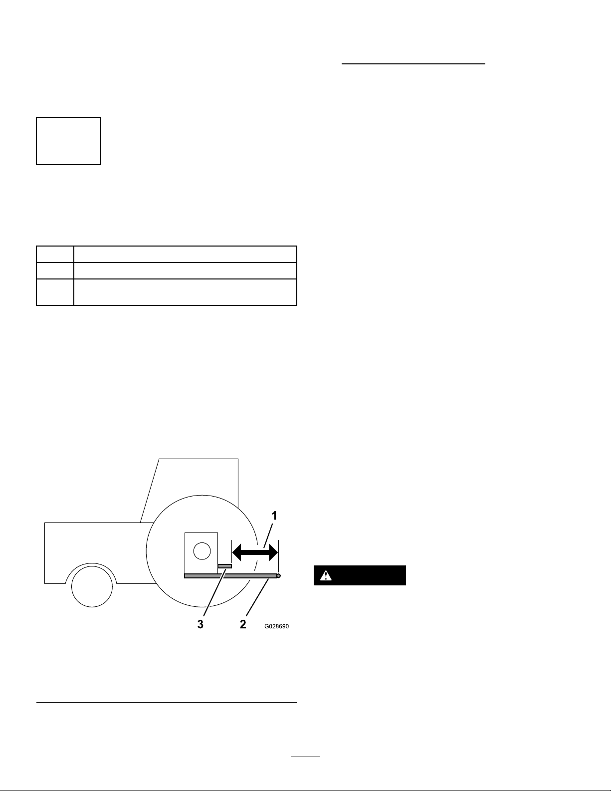
Figure4
3-PointHitchandPTOComponents
1.Lowerlinkarm
2.Upperlinkarm
BallastRequirements
3.PTOdriveshaft
4.Swaylink
WARNING
Mountingthemachinetotherearofthe
tractionunitdecreasestheweightonitsfront
axle.
Failuretoaddrequiredballastmayresultin
anaccidentandsevereinjuryordeath.
•Toensureadequatesteeringcontroland
stabilityyoumayneedtoaddballasttothe
frontofthetractionunit.
•Refertothetractionunitoperator'smanual
forballastrequirements.
2
ConnectingtheLowerLink
Arms
Partsneededforthisprocedure:
2Lynchpin
Procedure
1.Ensurethatthemachineispositionedonalevel
surfaceforinstallation.
2.EnsurethatthePTOisdisengaged.
g007332
9

3.Backthetractionunitsquarelyuptothemachine
untilthelowerlinkarmsarealignedwiththe
hitchpins.
4.Engagetheparkingbrake,shutofftheengine,
andremovethekeyfromtheignition.Waitfor
theengineandallmovingpartstostopbefore
leavingtheoperator'sseat.
Note:Formaximumgroundclearance,install
thehitchpinsinthelowermountingholesof
thehitchplateforthemachine(Figure5).T o
determinewhentousetheuppermounting
holes,refertosetupprocedure4Connectingthe
PTODriveshaft(page11).
3
ConnectingtheUpperLink
Partsneededforthisprocedure:
1Linkpin
1Lynchpin
Procedure
Note:Forbestaerationholequality,alignthefront
ofthemachineverticalwhileoperatingit(Figure7).
Adjusttheupperlinktocontrolthisangle.Referto
OperatingTips(page27)foradditionalinformation.
Figure5
1.Tophole(hitch
plate—machine)
5.Inserttherightandleftlowerlinkarmsontothe
hitchpins(Figure6).
2.Bottomhole(hitch
plate—machine)
Figure6
g028741
g007293
Figure7
1.Connecttheupperlinktothelowerholeinthe
bracketandsecureitwiththelinkpinandthe
lynchpin(Figure8).
g007292
1.Lowerlink2.Lynchpin
6.Securethelowerlinkarmstothehitchpinswith
thelynchpins(Figure6).
g007294
Figure8
1.Upperlink3.Lynchpin
2.Linkpin4.Locknut
10
2.Greasethethreadedsteelupperlinktubes.
3.Rotatetheupperlinktotightenthelink.Adjust
ituntiltheframeatthefrontofthemachineis
vertical(Figure8).
4.Tightenthelocknuttosecuretheupperlinkinto
position.
thelowertrailingarms(Figure9).Recordyour
measurementhere:
Important:ContactyourauthorizedT oro
distributorifyouneedanyassistancewhen
performingthismeasurementandifyou
needtoorderanoptionalshorterPTO
driveshaftassembly.
4
ConnectingthePTO
Driveshaft
Partsneededforthisprocedure:
1
Bolt(1/2x3inches)
1
Nut(1/2inch)
Shortdriveshaft,PartNo.1 15-2839(maybeneeded;
–
soldseparately)
DeterminingtheTrailingArm
LengthandPTODriveshaft
Important:RefertothePTOdriveshaftowner’s
manualforadditionaloperatingandsafety
information.
1.Placeastraightedgeacrosstheendsofthe
trailingarmstohelpyoudeterminethedistance
betweenthemandtheendofthePTOoutput
shaft(Figure9).
3.Determinewhetheryouneedastandardlength
PTOdriveshaftorashortPTOdriveshaftfrom
thepositionofthePTOoutputshaftonthe
tractionunit,relativetothepositionofthelower
trailingarms.Thisdistanceisdesignatedas“M”
dimension.
•ThestandardPTOdriveshaftincluded
withyourmachinetsatractionunit“M”
dimensionassmallas48.89cm(19.25
inches).
•Ifthe“M”dimensionissmaller,weofferan
optionalshortPTOdriveshaftassembly,
whichtsatractionunit“M”dimensionas
smallas39.37cm(15.50inches);referto
thePartsCatalogforyourmachine.
Important:Ifnecessary ,installthe
shortdriveshaft,PartNo.115-2839(sold
separately).Inmostcases,theshort
driveshaftisnotneeded.
4.Ifyourtractionunitisequippedwithadjustable
trailingarms,changethelengthoftrailingarms
untilthe“M”dimensionmeasures:
Refertotheoperator'smanualforyourtraction
unit.
Figure9
1.“M”dimension3.PTOoutputshaft(traction
unit)
2.Lowertrailingarms
2.Measurethedistancebetweentheendofthe
PTOoutputshaftandtheattachmentpointof
•48.89cm(19.25inches)orlongerforthe
standardPTOshaft
•39.37cm(15.50inches)orlongerforthe
optionalshortPTOshaft
InstallingthePTODriveshaft
CAUTION
OperatingthemachinewithoutthePTO
guardsandshieldsmaycauseinjuryordeath.
g028690
•KeepallPTOguardsandshieldsinplace.
•OnCEmodels,connectthechainsbetween
thePTOdriveshaftguardsandthelink
arms.
1.OntheProCore864only,removethelowerPTO
shield(Figure10).
11
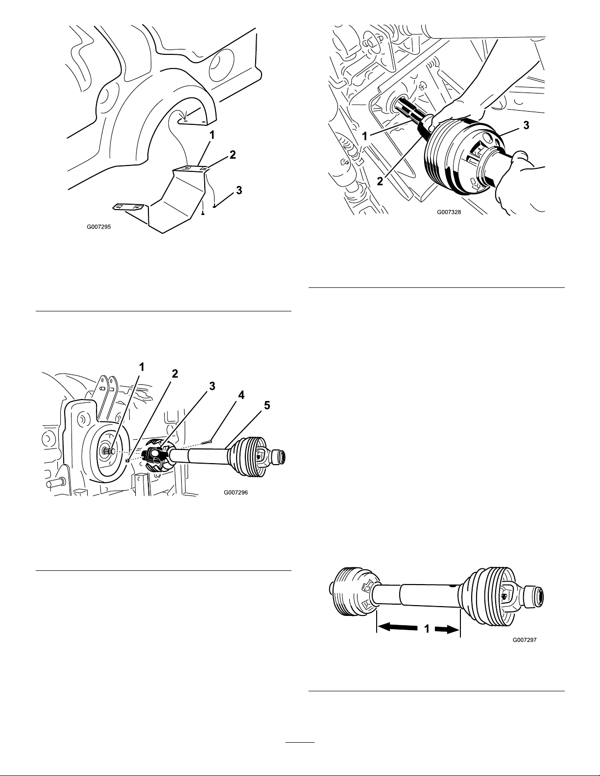
Figure10
ProCore864
1.LowerPTOshield3.Screw
2.Clipnut
2.AssemblethePTOdriveshafttothegearbox
inputshaftofthemachine(Figure11)withabolt
(1/2x3.00inches)andanut(1/2inch).
Figure11
1.Gearboxinputshaft
2.Nut
3.PTOshaftcoupler
4.Bolt
5.PTOdriveshaft
g007328
g007295
1.PTOoutputshaft(traction
unit)
2.PTOshaftcoupler
Figure12
3.PTOdriveshaft
4.SlidethePTOdriveshaftforwardasfarasthe
PTOoutputshaftallows.
5.PullbackonthelockingcollarofthePTOshaft
couplertosecurethePTOdriveshaft.Slidethe
PTOdriveshaftbackandforthtoensurethatit
islockedsecurely.
6.OnCEmodelsonly,connectthesafetychains
fromthedriveshaftguardstotheweldedclipson
thelinkarms.Makesurethatthechainsremain
slackwhenthemachineisraisedorlowered.
7.OntheProCore864,installthelowerPTOshield
tothemachine.
8.Verifythatthetelescopingtubehasaminimum
of76mm(3inches)overlapwhenthemachine
israisedtothemaximumheight.
g007296
Tochecktheoverlap,measurethedistance
betweentheendshields,asshowninFigure
13.Thisdimensionmustnotexceed406mm
(16inches).Ifso,movethelowerliftpinstothe
uppersetofholesbeforeoperatingthemachine.
3.AssemblethePTOdriveshafttothePTOoutput
shaftofthetractionunit.
g007297
Figure13
1.406mm(16inches)
12
 Loading...