


FormNo.3358-603RevC
ProCore864and1298Aerator
ModelNo.09715—SerialNo.280000001andUp
ModelNo.09716—SerialNo.280000001andUp
Registeratwww.T oro.com.OriginalInstructions(EN)

Contents
Introduction
Readthisinformationcarefullytolearnhowtooperate
andmaintainyourproductproperlyandtoavoidinjury
andproductdamage.Youareresponsibleforoperating
theproductproperlyandsafely.
YoumaycontactTorodirectlyatwww .Toro.comfor
productandaccessoryinformation,helpndinga
dealer,ortoregisteryourproduct.
Wheneveryouneedservice,genuineToroparts,or
additionalinformation,contactanAuthorizedService
DealerorToroCustomerServiceandhavethemodel
andserialnumbersofyourproductready .Figure1
identiesthelocationofthemodelandserialnumbers
ontheproduct.Writethenumbersinthespace
provided.
Figure1
1.Modelandserialnumberlocation
ModelNo.
SerialNo.
Thismanualidentiespotentialhazardsandhas
safetymessagesidentiedbythesafetyalertsymbol
(Figure2),whichsignalsahazardthatmaycauseserious
injuryordeathifyoudonotfollowtherecommended
precautions.
Figure2
1.Safetyalertsymbol
Thismanualuses2otherwordstohighlightinformation.
Importantcallsattentiontospecialmechanical
informationandNoteemphasizesgeneralinformation
worthyofspecialattention.
Introduction.................................................................2
Safety...........................................................................3
SafeOperatingPractices.......................................3
SafetyandInstructionalDecals.............................5
Setup............................................................................8
1TractorRequirements........................................9
2ConnectLowerLinkArms.................................9
3ConnectUpperLink........................................10
4ConnectPTOShaft.........................................10
5AdjustingSwayLinks.......................................12
6LevelAeratorSide-to-Side...............................12
7AdjustRollerScraper.......................................13
8InstallTineHeads&Tines...............................13
9InstallTurfGuards..........................................13
10SecureHoodLatches(CEonly)......................14
11RemoveStorageStands..................................14
ProductOverview......................................................16
Controls.............................................................16
Specications.....................................................16
Attachments/Accessories...................................16
Operation...................................................................19
AdjustingAerationDepth..................................19
TractorControls.................................................19
PrinciplesofOperation......................................19
TrainingPeriod...................................................20
BeforeAerating..................................................20
AeratingProcedures...........................................20
OperatingTips...................................................21
HardGround.....................................................21
NeedleTines......................................................21
RootZoneLifting..............................................21
AdjustingtheRotolinkAssembly........................22
TransportOperation..........................................22
InspectionandCleanupafterUse........................22
Maintenance...............................................................23
RecommendedMaintenanceSchedule(s)................23
JackingtheMachine............................................23
GreasingtheBearingsandBushings....................23
CheckingtheGearboxLubrication.....................25
ChangingtheGearboxLubrication.....................25
CheckCoringHeadFastenerT orque...................25
InspectingtheBelts............................................25
AdjustingtheBeltTension..................................25
ReplacingtheDriveBelt.....................................26
AdjustingtheSideShield....................................27
ReplacingtheTurfGuards..................................28
AdjustingHoleSpacing......................................28
CoringHeadTiming...........................................28
RemovingtheAeratorfromtheTractor...............29
Storage.......................................................................30
©2008—TheToro®Company
8111LyndaleAvenueSouth
Bloomington,MN55420
Contactusatwww.Toro.com.
2
PrintedintheUSA.
AllRightsReserved

Safety
Improperuseormaintenancebytheoperatoror
ownercanresultininjury.T oreducethepotential
forinjury,complywiththesesafetyinstructions
andalwayspayattentiontothesafetyalert
symbol,whichmeansCAUTION,WARNING,or
DANGER-"personalsafetyinstruction."Failureto
complywiththeinstructionmayresultinpersonal
injuryordeath.
SafeOperatingPractices
BeforeOperating
•OwnersofthisAeratormustgiveoperatorsand
employeesfulloperationandsafetyinstructions
beforeallowingthemtooperatethismachineandat
leastannuallythereafter.Anoperatorwhohasnot
readandfullyunderstoodalloperatingandsafety
instructionsisnotqualiedtooperatethismachine.
Becomefamiliarwithallcontrolsandknowhowto
stopquickly.
•Donotallowchildrentooperatethemachine.Do
notallowadultstooperatethemachinewithout
properinstruction.
•Removealldebrisorotherobjectsthatmight
interferewithoperation.Keepallbystandersaway
fromtheworkarea.
•Locateandmarkallundergroundobstructionssuch
asirrigationcomponents,electricalortelephone
lines.
•Makesuretractorisinneutralandparkingbrake
appliedbeforestarting.RefertoTractorOperator’s
Manualforsafestartingprocedures.
•MountingtheProCoreAeratortotherearofthe
tractorwilldecreasetheweightonthetractorfront
axle.Toassureadequatesteeringcontrolandstability
itmaybenecessarytoaddballasttothefrontof
thetractor.RefertoTractorOperator’sManualfor
ballastrequirements.
•Keepallshieldsandsafetydevicesinplace.Ifa
shield,safetydeviceordecalisdamaged,repairor
replaceitbeforeoperationiscommenced.Also
tightenanyloosenuts,boltsandscrewstoensure
machineisinsafeoperatingcondition.
•Donotoperatemachinewhilewearingsandals,
tennisshoes,sneakersorshorts.Also,donot
wearloosettingclothingwhichcouldgetcaught
inmovingparts.Alwayswearlongpantsand
substantialshoes.Wearingsafetyglasses,safety
shoes,hearingprotectionandahelmetisadvisable
andmayberequiredbysomelocalordinancesand
insuranceregulations.
WhileOperating
•Keepallbystandersandpetsawayfromthework
area.
•Usingthemachinedemandsattention,andto
preventlossofcontrol:
–Useonlyindaylightorwhenthereisgood
articiallight.
–Watchforholesorotherhiddenhazards.
–Donottransportmachineclosetoasandtrap,
ditch,creekorotherhazard.
–Reducespeedonsidehillsandbeforemaking
sharpturnstopreventtippingorlossofcontrol.
–Lookbehindtheaeratorbeforebackingup.
•Ifthetinesstrikeasolidobjectorthemachine
vibratesabnormally,disengagethePTO,setthe
parkingbrakeandshuttheengineoff.Removekey
fromignitionswitch.Checkaeratorandtractionunit
fordamage.Repairanydamagebeforerestartingthe
engineandoperatingthetines.Besuretinesarein
goodconditionandallboltsaretight.
•Beforeleavingmachineunattended,disengagepower
toaerator,loweraeratorandsetparkingbrake.Stop
engine.
•Neverdismountwhiletractorisinmotion.Never
getonorofftractorwhileengineisrunningand
PTOdriveshaftisengaged.NeverstepoverPTO
shafttoreachothersideofaerator-walkaround
themachine.
•Parkaeratoronahard,levelsurface,installaerator
storagestandsbeforedisconnectingfromtractor.
•Ifitisnecessarytoprobebelowthesoilsurface,use
anonconductivematerialtopreventelectricalshock
incaseelectricalwiresarepresent.
Transporting
•Besureyouareincompliancewithallregulations
regardingtransportingequipmentonthepublic
roadsandhighways.
•Ensurethatallreectorsandlightsrequiredarein
placeandarecleanandvisiblebyovertakingand
oncomingtrafc.
•Neverallowanyonetorideonthemachineduring
transport.
•Reducespeedonroughroadsandsurfaces
•Independentbrakesshouldalwaysbelockedtogether
whenontheroad.
3

PTOShaft
StorageSafety
•ForallPTOshaftsteelparts(tubes,bearings,joints
etc.)disassemblyorrepairs,itishighlyadvisable
tocontactyourlocalTorodistributor.Removalof
componentsforrepairsandreassemblymaydamage
somepartsifnotcarriedoutcorrectlyusingspecial
toolsavailableinadistributor’sworkshop.
•ThePTOshaftmustnotbeusedwithouttheguards
supplied,withpartialprotectionorwithdamaged
guard,oronCEmachines,withoutthespecial
anti-rotationchainscorrectlyhooked,soastopermit
themaximumangleofthePTOshaftwithout
breakingthechains.
Maintenance
•Beforemakingadjustmentsorperforming
maintenanceontheaerator,switchofftheengine,
stopthePTOandapplytheparkingbrakebefore
dismountingfromthetractor.Besuretheaeratoris
onthegroundorloweredontothesafetystands.
•Supportthemachinewiththeblocks,jacksoron
storagestandswhenworkingbeneathit.Neverrely
onthetractor’shydraulicstosupportthemachine.
•Storetheaeratoronarmlevelsurface.
•Storeaeratorawayfromareasofhumanactivity.
•Donotallowchildrentoplayonoraroundthe
storedmachine.
•Makesuretheaeratorispositionedonrmandsolid
groundsoitdoesnotsinkortipover.
•Ensurethatthestoragestandlynchpinsaresecured
inplace.
•Placeallcontrolsinneutral,stoptheengine,apply
parkingbrakeandwaitforallmovingpartsto
stopbeforeservicing,maintaining,adjustingor
unblockingtheaerator.
•Besuremachineisinsafeoperatingconditionby
keepingnuts,boltsandscrewstight.Checkthe
tinemountingboltsfrequentlytobesuretheyare
tightenedtospecication.
•Donotcheckoradjustbelttensionwhenthetractor
engineisrunning.
•Besureallguardsarereplacedandthehoodis
securedshutaftermaintainingoradjustingthe
machine.
•Performonlythosemaintenanceinstructions
describedinthismanual.Ifmajorrepairsare
everneededorassistanceisdesired,contactan
AuthorizedToroDistributor.Toensureoptimum
performanceandsafety,alwayspurchasegenuine
Tororeplacementpartsandaccessoriestokeepthe
ToroallToro.Neveruse"will-t"replacementparts
andaccessoriesmadebyothermanufacturers.Look
fortheTorologotoensuregenuineness.Using
unapprovedreplacementpartsandaccessoriescould
voidthewarrantyofTheToroCompany.
4

SafetyandInstructionalDecals
Safetydecalsandinstructionsareeasilyvisibletotheoperatorandarelocatednearanyareaof
potentialdanger.Replaceanydecalthatisdamagedorlost.
93-6696
1.Storedenergyhazard—readtheOperator’sManual.
110-4678
1.Coringdepth
1.ReadtheOperator’sManual.
110-4665
110-4667
1.Springlength
2.Storedenergyhazard—readtheOperator’sManual.
3.Entanglementhazard,belt—stayawayfrommovingparts.
1.Installthepostsinthe
standtotheholesinthe
frame.
110-4666
2.Usepinstosecurethe
frametothestand.
110-4668
1.Entanglementhazard,shaft—stayawayfrommovingparts.
2.PTOspeedandinputdirection.
3.Usecliptosecurelashcablewhennotinuse;uselash
cabletosupportthepowertakeoffwhenthemachineis
disconnectedfromtractor.
5

110-4670
1.Warning—readtheOperator’sManual.
2.Warning—removetheignitionkeyandreadtheinstructions
beforeservicingorperformingmaintenance.
3.Warning—receivetrainingbeforeoperatingthemachine.7.Crushinghazardofhandandbody—supportmachineon
4.Entanglementhazard,belt—stayawayfrommovingparts.
5.Entanglementhazard,belt—keepallguardsinplace.
6.Crushinghazardofhandorfoot—keepbystandersasafe
distancefromthemachine.
standwhennotinuse.
8.Fallinghazard—donotcarrypassengers.
1.Turnclockwiseto
decreaseaerationdepth.
92–1581
92–1582
110-4677
2.Turncounterclockwiseto
increaseaerationdepth.
6

106–8856
1.ReadtheOperator’sManual.
110-4664
1.ReadtheOperator’s
Manual.
2.Wrenchsize4.Torque
3.Boltsize
7

Setup
LooseParts
Usethechartbelowtoverifythatallpartshavebeenshipped.
ProcedureDescription
1
2
3
4
5
6
7
8
9
10
11
Qty.
Nopartsrequired
Lynchpin2
Linkpin1
Lynchpin1
Bolt(1/2x3inches)
Nut(1/2inches)
Nopartsrequired
Nopartsrequired
Nopartsrequired
Nopartsrequired
Turfguards(notincluded)A/RInstallTurfGuards
CEComplianceKit,PartNo.110–4693
(notincluded)
Lynchpin(ProCore864)
Lynchpin(ProCore1298)
–
1
1
–
–
–
–
1
4
8
TractorandballastRequirements
ConnectLowerLinkArms
ConnecttheUpperLink
ConnectPTOShaft
AdjustingSwayLinks
LevelAeratorSide-to-Side
AdjustRollerScraper
InstallTineHeads&Tines
SecureHoodLatches(RequiredforCE
only)
RemoveStorageStands
Use
8

1
TractorRequirements
NoPartsRequired
Procedure
ProCore864
•30PTOhorsepowerminimumwhenusedinlightto
normalconditions(sandytosandy/loamsoilswith
averagecompaction).
•35PTOhorsepowerminimumwhenusedinnormal
toheavyconditions(heavyloam,clayandrockysoils
withaboveaveragecompaction).
•CategoryIorII3pointhitch,ratedtoliftatleasta
1575lb.(714Kg)implement.
TractorComponents(Figure3)
Figure3
1.Lowerlinkarm
2.Upperlinkarm
3.PTOshaft
4.Swaylink
•540rpmtractorPTO˙.
•Adequatefront-endweight(ballast).
•Correcttirepressure.
Donotexceedthemaximumorminimum
tractortireinationpressuresasrecommended
bytiremanufacturer.
ProCore1298
•45PTOhorsepowerminimumwhenusedinlightto
normalconditions(sandytosandy/loamsoilswith
averagecompaction).
•50PTOhorsepowerminimumwhenusedinnormal
toheavyconditions(heavyloam,clayandrockysoils
withaboveaveragecompaction).
•CategoryII3pointhitch,ratedtoliftatleasta2300
lb.(1043Kg)implement.
•540rpmtractorPTO˙.
•Adequatefront-endweight(ballast).
BallastRequirements
MountingtheProCoreaeratortotherearofthe
tractorwilldecreasetheweightonthefront
axle.
•Toassureadequatesteeringcontroland
stabilityitmaybenecessarytoaddballast
tothefrontofthetractor.
•RefertotractorOperator’sManualfor
ballastrequirements.
•Failuretoaddrequiredballastmayresultin
anaccidentandsevereinjuryordeath.
2
ConnectLowerLinkArms
Partsneededforthisprocedure:
•Correcttirepressure.
Donotexceedthemaximumorminimum
tractortireinationpressuresasrecommended
bytiremanufacturer.
2Lynchpin
Procedure
1.Aeratormustbepositionedonaat,levelsurface
forinstallation.
2.Backtractorsquarelyuptoaeratoruntillowerlink
armsarealignedwithhitchpins.
9

3.MakesurePTOisdisengaged.
4.Engageparkingbrake,STOPengineandremovekey
fromignition.Waitforengineandallmovingparts
toSTOPbeforeleavingOperator’sseatontractor.
Note:Formaximumgroundclearancethehitch
pinsshouldbesecuredinthelowermountingholes.
Todeterminewhentousetheuppermountingholes,
refertoConnectingthePTOShaft.
5.Insertrightandleftlowerlinkarmsontohitchpins
(Figure4).
Figure5
1.Connectupperlinktolowerholeinbracketand
securewithlinkpinandlynchpin(Figure6).
Figure4
1.Lowerlink2.Lynchpin
6.Securelowerlinkarmstohitchpinswithlynchpins
(Figure4).
3
ConnectUpperLink
Partsneededforthisprocedure:
1Linkpin
1Lynchpin
Procedure
Note:Thefrontofaeratormustbeverticalwhile
operatingforbestaerationholequality(Figure5).Adjust
upperlinktocontrolthisangle.RefertoOperationfor
additionalinformation.
Figure6
1.Upperlink3.Lynchpin
2.Linkpin4.Locknut
2.Greasethethreadedsteelupperlinktubes.
3.Rotatetheupperlinktotightenthelink.Adjustuntil
frontofaeratorframeis90degreesfromhorizontal
(Figure6).
4.Tightenlocknuttosecureupperlinkintoposition.
10

4
ConnectPTOShaft
Partsneededforthisprocedure:
1
Bolt(1/2x3inches)
1
Nut(1/2inches)
Procedure
1.OntheProCore864only,removethelowerPTO
shield(Figure7).
Figure8
1.Gearboxinputshaft
2.Nut
3.PTOshaftcoupler
4.Bolt
5.PTOshaft
3.ConnectPTOshafttoreartractorPTOshaft.
Figure7
1.LowerPTOshield
(ProCore864only)
2.Tinnermannut
3.Screw
2.ConnectPTOshafttogearboxinputshaftwitha
1/2x3.00inchboltand1/2inchnut(Figure8).
Figure9
1.Tractoroutputshaft3.PTOshaft
2.PTOshaftcoupler
4.SlidePTOshaftforwardasfarasthetractorallows.
5.PullbackonthelockingcollartosecurethePTO
shaftinplace.SlidePTOshaftbackandforthto
makesureitisproperlylocked.
6.OnCEmodelsonly,connecttheshieldsafetychains
frompowershaftsectionstoweldedclipsonlink
arms.Makesurechainsremainslackwhenaerator
israisedorlowered.
Tohelppreventbodilyinjury,keepallPTO
shieldsinplace.OnCEmodels,connectthe
shieldchainstolinkarmstopreventshields
fromrotatingduringoperation.
11

7.OntheProCore864,installthelowerPTOshield
totheaerator.
8.Verifythatthetelescopingtubehasaminimumof
3inches(76mm)overlapwhentheaeratorisraised
toit’ smaximumheight.
Tochecktheoverlap,measurethedistancebetween
theendshields,asshowningureFigure10.This
dimensionmustnotexceed16.00inches(406mm).
Ifso,thelowerliftpinsMUSTbemovedtothe
uppersetofholespriortooperation.
Figure10
1.16.00inches(406mm)
5
Figure11
1.Swaylink
Adjustthelowerlinksinboarduntiltheycontactthe
aeratormountingplates.Thiswillreducethestress
onthepins.Ifthetractorhasswaychainsinsteadof
swaylinks,itisrecommendedthatwashersbeinstalled
betweenthelowerlinkarmandlynchpintoreducethe
overhungloadontheliftpins.
AdjustingSwayLinks
NoPartsRequired
Procedure
TheProCore864isdesignedtobeoffsetfromthe
tractorcenterline.ThePTOshaftisoffset1.57inches
totheleftofcenterandtheaeratorisoffset5.70inches
totherightofthecenterline.Adjusttheswaylinksas
required.
TheProCore1298isdesignedtobecenteredwiththe
tractorcenterline.Adjusttheswaylinksasrequired.
Adjustswaylinksonlowerdraftarmsof3pointhitchto
minimizeside-to-sideswaytoamaximumof1inch(25
mm)oneachside(Figure11).
Note:RefertotractorOperator’sManualforadditional
installationandadjustmentprocedures.
6
LevelAeratorSide-to-Side
NoPartsRequired
Procedure
1.Parktractorandaeratoronalevel,rmsurface.
2.Placelevelontopofaeratorframetocheckforlevel
side-to-side(Figure12).
12

2.Slidetherollerscraperinoroutuntilrequired
positionisattainedandtightenfasteners.
3.OntheProCore864only,thestopboltonthecenter
supportmayalsobeadjustedtoattaintheproper
gap.
Figure12
1.Level
3.Turntheadjustablelinkbody(ifprovided)toraise
orlowerthelinkarmuntiltheaeratorisleveled
side-to-side.
Note:RefertotractorOperator’sManualfor
additionaladjustmentprocedures.
7
AdjustRollerScraper
NoPartsRequired
Procedure
Therollerscrapershouldbeadjustedsothereisagap
ofapproximatelya.06-.09inches(1-2mm)betweenthe
scraperandroller.
1.Loosenfastenerssecuringeachendofscraperto
rollerscrapertab(Figure13).
8
InstallTineHeads&Tines
NoPartsRequired
Procedure
Awideselectionoftinesandtineheadsareavailable
fortheaerator.Choosethetinetype,sizeandspacings
requiredforthejob.Installthetineheadandtinesper
InstallationInstructionssuppliedwitheachtinekit.
Refertothechartsonpages17&18fortheaccessories.
Important:Neveroperatetheaeratorwithout
thetineheadsinstalled.Thearmsmaymove
excessivelyanddamagetheaeratorframe.
9
InstallTurfGuards
Partsneededforthisprocedure:
A/RTurfguards(notincluded)
Figure13
1.Rollerscraper2.Nut
Procedure
Awideselectionofturfguardsareavailableforthe
aerator.Usetheappropriateturfguardsfortheselected
tineheads.
1.Loosennutssecuringturfguardclampstoturfguard
toolbar(Figure14).
13

Figure14
1.Turfguard2.Turfguardclamp
2.Slideappropriateturfguardunderturfguardclamp.
3.Adjusttheturfguards,lefttoright,tomaintain
equaldistancetotineswithineachslot.Tightennuts
securingturfguard.
4.Mountremainingturfguardsandsecureturfguard
clamps.
Important:Fromtherearofthemachine,
checkthatthetineslineupwiththecenterof
thegapsintheturfguards.
10
SecureHoodLatches(CE
only)
Partsneededforthisprocedure:
1
CEComplianceKit,PartNo.110–4693(notincluded)
Procedure
Figure15
1.Tapbolt3.Internallockwasher
2.Lockbracket4.Rearcover
2.OntheProCore1298model,installalockbracket
overalltherearlowerhoodlatchesandtheoutside
upperhoodlatchonbothrightandleftrearcovers
withatapbolt(threepercoringhead,sixtotal)
(Figure15).
3.Usingapliersoradjustablewrench,threadan
internallockwasherontoeachbolt(1-2threads)to
securelatch(Figure15).
11
RemoveStorageStands
Partsneededforthisprocedure:
4
Lynchpin(ProCore864)
8
Lynchpin(ProCore1298)
Note:CECompletionKit,PartNo.110–4693is
requiredtocompletethisstep.
1.OntheProCore864model,installalockbracket
overtheleftandrightrearlowerhoodandupper
hoodlatcheswithatapbolt(fourtotal)(Figure15).
Procedure
1.Raisetheaerator3-6inchesoffground.
2.Removethenutsandlockwasherssecuringthe
storagestandstotheaerator(Figure16).
14
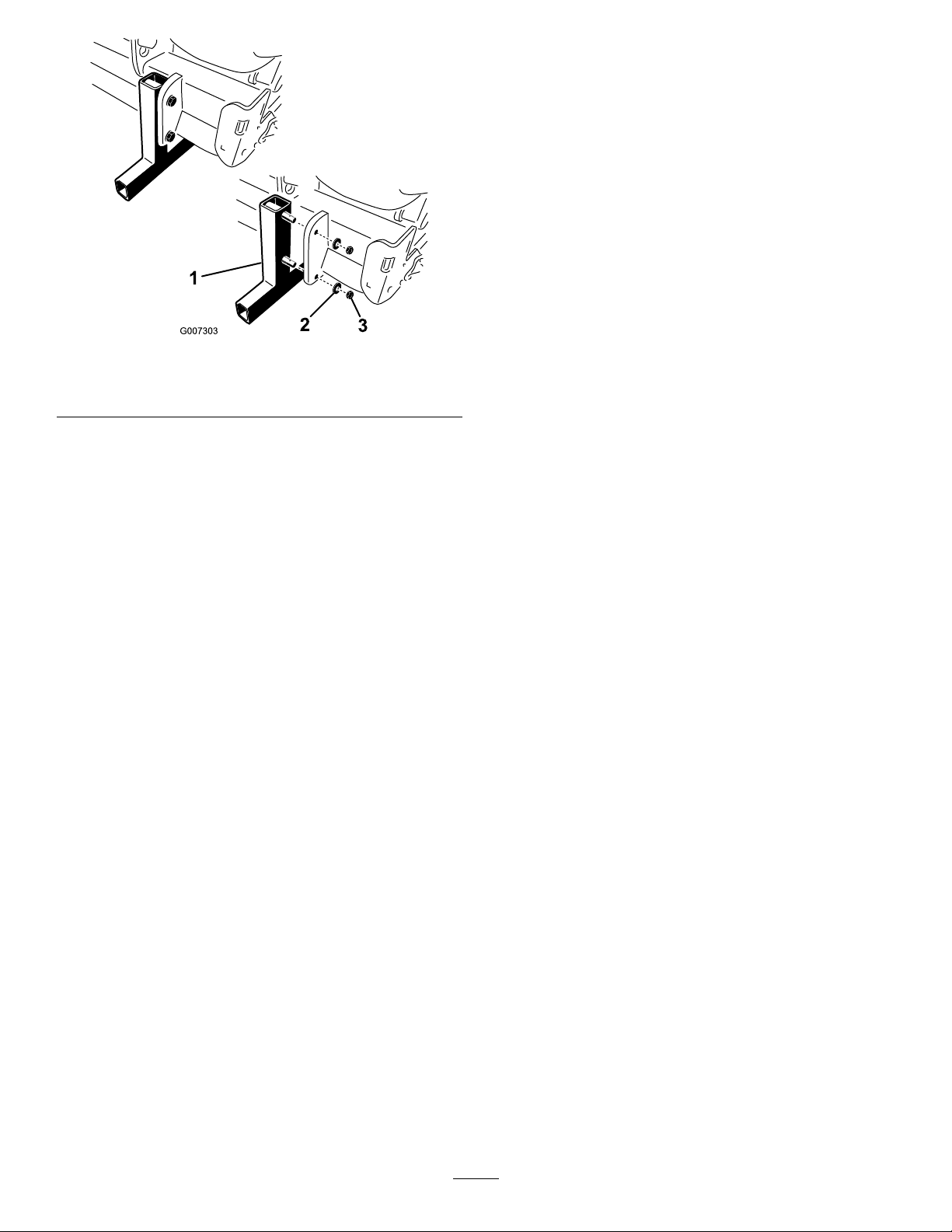
Figure16
1.Storagestand
2.Lockwasher
3.Nut
3.Removethestoragestands.
4.Insertthelynchpins(includedinlooseparts)into
thestandpinsforstorage(Figure16).
5.Usethestoragestandswhenevertheaeratoris
removedfromthetractor.
15

ProductOverview
Controls
DepthAdjuster
Rotatethedepthadjusterinputshaftclockwise(CW)to
reducetheaerationdepthorrotatecounterclockwise
(CCW)toincreasetheaerationdepth(Figure17).
Specications
Note:Specicationsanddesignaresubjecttochange
withoutnotice.
ProCore864Aerator
WorkingWidth
OverallWidth67inches(170cm)
OverallLength35inches(89cm)
OverallHeight38.5inches(98cm)
64inches(163cm)
Figure17
1.Depthadjusterinputshaft
2.Lockingplate4.Depthalignmentmark
3.Depthindicatordecal
Note:Seventeen(17)revolutionsofthedepthadjuster
equalsapproximately1/4inch(6.4mm)depthchange.
Weight
ProCore1298Aerator
WorkingWidth
OverallWidth101inches(257cm)
OverallLength35inches(89cm)
OverallHeight38.5inches(98cm)
Weight
1,575pounds(714Kg)
98inches(249cm)
2300pounds(1043Kg)
Attachments/Accessories
AselectionofToroapprovedattachmentsand
accessoriesareavailableforusewiththemachineto
enhanceandexpanditscapabilities.Contactyour
AuthorizedServiceDealerorDistributororgoto
www.Toro.comforalistofallapprovedattachments
andaccessories.
16

Figure18
17

Figure19
18

Operation
Note:Determinetheleftandrightsidesofthe
machinefromthenormaloperatingposition.
AdjustingAerationDepth
Adjusttheaerationdepthonlywhenthetractor
isparked,theparkingbrakeisengaged,the
engineisoffandthePTOisdisengaged.
1.Laythedesiredtineontothedepthdecalwhile
aligningthetinetipwiththedesiredaerationdepth
asshowninFigure20.
Figure21
1.Depthadjusterinputshaft
2.Lockingplate4.Depthalignmentmark
4.Pushinonthesocketoruseyourhandtodepress
thelockingplate.
5.Rotatethedepthadjusterclockwise(CW)toreduce
theaerationdepthorrotatecounterclockwise
(CCW)toincreasetheaerationdepth.(Figure21).
6.Rotatethedepthadjusterinputshaftuntilthe
desireddepthisattainedasshownonthedepth
indicatordecal(Figure21).
3.Depthindicatordecal
Figure20
2.Determinethelettersettingalignedwiththe
mountingendoftine(Figure20).Adjustthedepth
controltothecorrespondingletteronthedecal.
3.Inserta9/16”socketw/ratchetontothedepth
adjusterinputshaft(Figure21).
Note:Seventeen(17)revolutionsofthedepth
adjusterinputshaftequalsapproximately1/4inch
(6.4mm)depthchange.
TractorControls
Itisnecessarytofamiliarizeyourselfwiththeoperation
ofthefollowingtractorcontrolsbeforeyouareableto
operatetheaerator:
•PTOEngagement
•3PointHitch(Raise/Lower)
•Clutch
•Throttle
•GearSelection
•Parkingbrake
Note:RefertotractorOperator’sManualfor
operatinginstructions.
PrinciplesofOperation
Thetractor’ sthreepointhitchlinkageliftstheaerator
fortransportandlowersitforoperation.
Thetractor’spowertakeoff(PTO)poweristransmitted
viashafts,gearboxanddrivebeltstoanumberof
crankshaftswhichdrivethetineholdingarmsintothe
turfsurface.
19

AsthetractortravelsforwardwiththePTOengaged
andthemachinelowered,aseriesofholesarecreated
intheturfsurface.
Thedepthofthetine’spenetrationisdeterminedbythe
heightofthedepthcontrol.
Thedistancebetweentheholescreatedisdetermined
bythetractor’sgearratio(orhydrostatictractionpedal
position)andthenumberoftinesineachtinehead.
Simplychangingenginerpmdoesnotchangehole
spacing.
TrainingPeriod
Beforeusingtheaerator,ndaclearareaandpractice
usingthemachine.Operatethetractoratrecommended
gearsettingsandPTOdrivespeedsandbecome
thoroughlyfamiliarwithmachinehandling.Practice
stoppingandstarting,raisingandloweringtheaerator,
disengagingthePTOdriveandaligningthemachine
withpreviouspasses.Apracticesessionassures
condenceintheperformanceoftheaeratorandhelps
ensureuseofproperoperatingtechniqueswherever
themachineisoperated.
Iftherearesprinklerheads,electricalorcommunication
linesorotherobstructionsintheareatobeaerated,
marktheseitemstoensuretheyarenotdamagedduring
operation.
Toavoidpersonalinjury,neverleavethetractor
seatwithoutrstdisengagingthePTOdrive,
settingtheparkingbrakeandstoppingthe
engine.Neverperformaeratorrepairswithout
rstloweringtheaeratorontothestorage
standorappropriateblockingorjacks.Besure
allsafetydevicesaresecuredinproperplace
beforeresumingoperation.
AeratingProcedures
Note:Whenusingneedletineheads,makesuretoread
instructions,includedwithkit,foruniqueoperating
procedure.
1.Lowertheaeratoronthe3pointlinkagesothatthe
tinesarenearlytothegroundatthelowestpartof
theirstroke.
2.Atalowtractorenginerpm,engagethepowertake
off(PTO)clutchtostarttheaeratorworking.
Important:Neveroperatetheaeratorwithout
thetineheadsinstalled
3.Selectagearthatgivesaforwardspeedof
approximately.6-2.5M.P .H.(1to4km/hr.)at
theratedPTOspeedof540(refertothetractor
Operator’sManual).
4.Astheclutchisreleasedandthetractormoves
forward,lowerthemachinefullyintotheturfand
increaseenginespeedtogiveamaximumof540
rpmatthePTO.
Important:NeveroperatethetractorPTO
inexcessof540rpmordamagetotheaerator
couldoccur.
Note:Makesurethattherollerisontheground.
5.Notetheholepattern.Ifyourequiregreaterhole
spacing,increaseforwardthespeedofthetractorby
shiftingupagearorwithahydrostaticdrivetractor,
actuatethehydrostatleverorpedaltogivefaster
speed.Forcloserholespacing,decreasetractor
forwardspeed.Changingenginespeed,ina
particulargear,willnotchangetheholepattern.
Important:Lookbehindfrequentlyto
ensurethemachineisoperatingproperlyand
alignmentismaintainedwithpreviouspasses.
6.Usethefronttractorwheelasaguidetomaintain
equallateralholespacingwiththepreviouspass.
7.Attheendoftheaerationpass,raisetheaeratorand
disengagethePTO.
BeforeAerating
Inspecttheareaofoperationforhazardsthatcould
damagethemachineandremovethem,ifpossible,or
planhowtoavoidthem.Carryreplacementtinesand
toolsincasetinesaredamagedduetocontactwith
foreignmaterials.
8.Ifyoubackintoatightarea(likeateebox),
disengagethePTOandraisetheaeratortoits
highestposition.Usecautionnottocatchtheturf
guardsontheturf.
9.Alwayscleartheareaofalldamagedmachineparts,
suchasbrokentines,etc.,topreventanything
frombeingpickedupbymowersorotherturf
maintenanceequipmentandthrown.
10.Replacebrokentines,inspectandcorrectdamageto
thosestillusable.Repairanyothermachinedamage
beforecommencingoperation.
20

OperatingTips
1.EngagePTOatlowenginespeed.Increaseengine
speedtoachievePTOspeedof540rpm(maximum)
andtheloweraerator.Operateatanenginerpm
thattheaeratorrunsmostsmoothly.
Note:Changingengine/PTOrpminaparticular
tractorgear(orxedhydrostaticpedalposition
ontractorswithhydrostatictransmission)willnot
changeholespacing.
2.Makeverygradualturnswhenaerating.Nevermake
sharpturnswithPTOdriveengaged.Planyour
aerationpathbeforeloweringtheaerator.
frombeingpickedupbymowersorotherturf
maintenanceequipmentandthrown.
10.Replacebrokentines,inspectandcorrectdamageto
thosestillusable.Repairanyothermachinedamage
beforecommencingoperation.
HardGround
Ifthegroundistoormtoobtainthedesiredcoring
depth,thecoringheadcangetintoa“bouncing”
rhythm.Thisisduetothehardpanthetinesare
attemptingtopenetrate.Thisconditioncanbe
correctedbyattemptingoneormoreofthefollowing:
3.Iftractor“bogs”downwhenoperatingonhard
groundorgoinguphill,raiseaeratorslightlyuntil
speedisregained,thenloweraeratoragain.
4.Donotaerateifgroundistoohardordry.Best
resultsareobtainedafterarainorwhenturfhas
beenwateredthepreviousday.
Note:Iftherollerridesupoffthegroundwhile
aerating,thegroundistoohardtoachievethe
desireddepth,reducetheaerationdepthuntilthe
rollercontactsthegroundduringoperation.
5.Raiseaeratorpenetration,ifgroundishardpacked.
Cleanupcoresandre-aerateatdeeperpenetration,
preferablyafterwatering.
6.TheProCore864aeratorisoffsettothetractor’s
rightsidetoallowaeratingwithoutdrivingoverthe
coreswiththetractortires.Wheneverpossible,
aeratewiththelongeroffsettowardstheprevious
aerationpass.
7.Alwayscheck/adjusttoplinkwheneveraeration
depthischanged.Thefrontoftheaeratorshould
bevertical.
Toavoidpersonalinjury,neverleavethetractor
seatwithoutrstdisengagingthePTOdrive,
settingtheparkingbrakeandstoppingthe
engine.Neverperformaeratoradjustments
orrepairswithoutrstloweringtheaerator
ontothesafetystand.Besureallsafetydevices
aresecuredinproperplacebeforeresuming
operation.
•Bestresultsareobtainedafterarainorwhenturf
hasbeenwateredthepreviousday.
•Reducethenumberoftinesperstomper
arm.Attempttomaintainasymmetricaltine
congurationtoevenlyloadthestomperarms.
•Reduceaeratorpenetration(depthsetting)ifground
ishardpacked.Cleanupcores,waterturf,and
aerateagainatadeeperpenetration.
Aerationofsoiltypesbuiltontopofhardsubsoils
(i.e.sand/soilcapplacedoverrockyground)cancause
undesiredholequality.Thisiscausedwhentheaeration
depthisgreaterthanthesoilcapandthesubsoilis
toohardtopenetrate.Whenthetinescontactthis
subsoiltheaeratormayliftandcausethetopofthe
holestobecomeelongated.Reducetheaerationdepth
sufcientlytoavoidpenetrationintothehardsubsoil.
NeedleTines
Longslendertinesusedineitheraneedletinehead
orminitineheadcanleavethefrontorrearofthe
holetuftedorslightlydeformed.Holequalityforthis
congurationgenerallyimprovesifthecoringhead
speedisreduced10-15%fromfulloperatingspeed.For
PTOpoweredaeratorsreducedtheenginespeeduntil
thePTOspeedisaround460–490rpm.Theforward
spacingisnoteffectedbyreducingtheenginespeed.
Thepushedholecanalsobeaffectedbythepositionof
therotalinkdamperassembly.RefertoAdjustingthe
RotolinkAssembly.
RootZoneLifting
8.Lookbehindfrequentlytoensurethemachineis
operatingproperlyandalignmentismaintainedwith
previouspasses.
9.Alwayscleartheareaofalldamagedmachine
parts,suchasbrokentines,etc.,topreventthem
Usingthemini-tineheadsinconjunctionwithlarger
coringtinesorlargediametersolidtinescaninduce
signicantstressontherootzoneoftheturf.This
stresscanfracturetherootzoneandcausealifting
actiontotheturf.Ifthisdamageoccurstryoneor
moreofthefollowing:
21

•Reducetinedensity(removesomeofthetines)
•Decreasecoringdepth(suggestedin1/2inch
increments)
•Increaseforwardholespacing(changetractor
transmissionuponegear)
•Decreasethetinediameter(solidorcoring)
AdjustingtheRotolink
Assembly
Themountingheightoftherotalinkdamperassembly
affectsthereactiveforceappliedtothestomperarm
andgroundengagementduringaeration.Intheevent
ofthefrontoftheholebeingpushed(elongatedor
dimpled),a“stiffer”positioncanhelpresistthispush
andimproveholequality .Intheeventofthebackof
theholebeingpushed(elongatedordimpled)a“softer”
positioncanimprovetheholequality.
Toadjusttherotolinkassembly ,proceedasfollows:
1.Removethe(2)1/2inchlocknutssecuringthe
rotolinkdamperassemblytotheundersideofcoring
headframe(Figure22).
2.Lowerthedamperassemblytoexposethespacers
(Figure22).
3.Moveoneortwospacerspersidefromthedamper
assemblytothetopofthecoringheadframe.Each
spacerisequivalentto1/2inch.Thelowerbumper
spacermustremainondamperassembly.
Toseetheeffectsofthisadjustment,itissuggested
thatonlythreetofourassembliesbeadjustedto
comparetheoriginalpositionandthenewposition
onatrialpass.Whensatisfactoryresultsare
achieved,movetheremainingassembliestothe
sameheightasthedesiredarms.
TransportOperation
Tobegintransportoperation,raisetheaeratorand
disengagethePTO.Toavoidlossofcontrol,traverse
steepinclinesslowly,approachroughareasatreduced
speedandcrosssevereundulationscarefully .
Important:Donotexceedtransportspeedsof15
m.p.h.(24km/hr.).
InspectionandCleanupafter
Use
Afterdailyuse,thoroughlywashthemachinewith
agardenhosewithoutanozzlesocontamination
andsealandbearingdamageduetoexcessivewater
pressurewillbeavoided.Abrushmaybeusedto
removecaked-onmaterial.Usemilddetergenttoclean
thecovers.Aftercleaning,greasealldrivelinesand
rollerbearings,inspectformachinedamage,oilleakage,
componentandtinewear.
Remove,cleanandoilthetines.Sprayalightoilmist
oncoringheadbearings(crank&damperlinks).
Figure22
1.Rotolinkdamperassembly4.Dwasher
2.Lowerbumperspacer5.Locknut
3.Spacer(s)
4.Reassemblethedamperassemblytothecoringhead
frame.Ensurethe“D”washerisinstalledagainst
thecoringheadframeasshowninFigure22.Secure
the(2)locknuts.
22

Maintenance
RecommendedMaintenanceSchedule(s)
MaintenanceService
Aftertherst8hours
Beforeeachuseordaily
Every50hours
Every100hours
Every250hours
Every500hours
Beforestorage
JackingtheMachine
Interval
Yearly
MaintenanceProcedure
•ChangetheGearboxLubrication
•Checkthetorqueofthecoringheadfasteners
•Checkthebelttension
•Checkbelttension
•Greasebearingsandbushings
•Inspectbearings
•Checkgearboxlubrication
•ChangetheGearboxLubrication
•Checkthetorqueofthecoringheadfasteners
•Inspectbearingsandreplaceasneeded
•Performall50hourmaintenanceprocedures
•Chippedsurfaces-Paint
•Removeandcleantines
•Removealldebris
•Inspectthebelts
Whenchangingattachmentsorperforming
otherservice,usecorrectblocks,hoistsor
jacks.Makesuremachineisparkedonasolid
levelsurfacesuchasaconcreteoor.Priorto
raisingmachine,removeanyattachmentsthat
mayinterferewiththesafeandproperraising
ofthemachine.Alwayschockorblocktow
vehiclewheels.Usejackstandsorsolidwood
blockstosupporttheraisedmachine.Ifthe
machineisnotproperlysupportedbyblocks
orjackstands,themachinemaymoveorfall,
whichmayresultinpersonalinjury.
Note:Ifavailable,ahoistcanbeusedtolifttherearof
theProCoreAerator.Useeyeletsincoringheadbearing
housingsashoistattachmentpoints(Figure23)
Figure23
1.Liftingeyelet
GreasingtheBearingsand
Bushings
ServiceInterval:Every50hours
Themainworkingbearingsoftheaeratoraresealed
forlifeandrequirenomaintenanceorlubrication.
Thisdrasticallyreducesthemaintenancerequiredand
eliminatestheriskofgreaseoroilbeingdroppedonto
theturf.
23

Therearegreasettingsthatmustbelubricatedwith
anSAEmultipurpose,high-temperaturegreasewith
highpressure(EP)performanceorSAEmultipurpose
lithiumbasegrease.
Thelubricationpointsare:
PTOShaft(3)(Figure24)
Figure24
Rollerbearings(ProCore864qty.2;ProCore1298qty .
4)(Figure25)
Figure26
Important:Bearingsrarelyfailfromdefectsin
materialsorworkmanship.Themostcommon
reasonforfailureismoistureandcontamination
workingitswaypasttheprotectiveseals.Bearings
thataregreasedwillrelyuponregularmaintenance
topurgeharmfuldebrisfromthebearingarea.
Sealedbearingsrelyonaninitialllofspecialgrease
andarobustintegralsealtokeepcontaminantsand
moistureoutoftherollingelements.
Figure25
Driveshaftbearings(ProCore864qty.1;ProCore1298
qty.2)(Figure26)
Thesealedbearingsrequirenolubricationorshortterm
maintenance.Thisminimizesroutineservicerequired
andreducesthepotentialofturfdamageduetogrease
contamination.Thesesealedbearingpackageswill
providegoodperformanceandlifeundernormaluse,
butperiodicinspectionsofbearingconditionandseal
integrityshouldbeconductedtoavoiddowntime.These
bearingsshouldbeinspectedseasonallyandreplacedif
damagedorworn.Bearingsshouldoperatesmoothly
withnodetrimentalcharacteristicssuchashighheat,
noise,loosenessorrustweeping
Duetotheoperatingconditionsthesebearing/seal
packagesaresubjectto(i.e.sand,turfchemicals,water,
impacts,etc.)theyareconsiderednormalwearitems.
Bearingsthatfailduetootherthandefectsinmaterialsor
workmanshiparetypicallynotcoveredunderwarranty.
Note:Bearinglifecanbenegativelyaffectedby
improperwashdownprocedures.Donotwash
downtheunitwhenitisstillhotandavoiddirecting
high-pressureorhighvolumesprayatthebearings.
Itiscommonfornewbearingstopurgesomegrease
outthesealsonanewunit.Thispurgedgreasewillturn
blackincolorduetocollectionofdebrisandnotdueto
excessiveheat.Itisgoodpracticetowipethisexcess
greasefromthesealsaftertheinitial8hours.Theremay
alwaysappeartobeawetareaaroundtheseallip.This
24

isgenerallynotdetrimentaltobearinglife,butkeeps
thesealliplubricated.
Coringheadbearingreplacementissuggestedat
intervalsof500hours.Abearingservicekitwhich
coversthecompletecoringheadisavailablefromyour
distributor.
CheckingtheGearbox
Lubrication
ServiceInterval:Every100hours
Thegearboxislledwith80W–90gearoilorequivalent.
Allowthegearboxtocoolbeforecheckingthe
lubrication.
1.Cleandebrisfromllplugandcheckplugtoavoid
contamination.
2.Removethecheckplugfromthegearbox(Figure27).
1.Cleandebrisfromllpluganddraincaptoavoid
contamination(Figure27).
2.Removethellplugtorelieveairdraw .
3.Positionadrainpanunderthedraintubeandremove
draincap.
Note:Thehighviscosityofcooloilwillextendthe
draintime.(approximately30minutes)
4.Afteroiliscompletelydrained,reinstallthedraincap.
5.Fillwith56ounces(1650ml)ofhighquality80W -90
gearlube.
6.Installthellplug.
7.Checktheoillevel.
CheckCoringHeadFastener
Torque
ServiceInterval:Aftertherst8hours
Every250hours
Aftertheinitial,eight(8)hoursofuse,checkthecoring
headfastenerstoensurepropertorqueismaintained.
Fastenertorquerequirementsarelistedonthereference
servicedecalbelowandlocatedonthecoringhead.
Figure27
1.Fillplug3.Drainplug
2.Checkplug(rearof
gearbox)
3.Makesureoilisuptothebottomofthecheckplug
holeingearbox(Figure27).
4.Ifoillevelislow,removellplugfromgearboxand
replenishoilasrequired.
5.Installplugs.
ChangingtheGearbox
Lubrication
ServiceInterval:Aftertherst8hours
Every250hours
Thegearboxislledwith80W–90gearoilorequivalent.
Figure28
1.ReadtheOperator’s
Manual.
2.Wrenchsize4.Torque
3.Boltsize
InspectingtheBelts
ServiceInterval:Yearly
Thedrivebelt(s)ontheProCoreAeratorshavebeen
designedtobeverydurable.However,thenormal
exposuretoUVradiation,ozoneorincidentalexposure
tochemicalscandeterioratetherubbercompounding
overtimeandleadtoprematurewearormaterialloss
(i.e.chunking).
Annualbeltinspectionishighlyrecommendedforsigns
ofwear,excessivecushioncracks,orlargeembedded
debriswithreplacementwhenneeded.
AdjustingtheBeltTension
ServiceInterval:Beforeeachuseordaily
25

Makesurebeltsareproperlytensionedtoensurecorrect
operationofunitandunnecessarywear.
1.Properbelttensionisattainedbycompressing
idlerspringtoalengthof5.75inches(146mm)
(Figure29).
Figure31
1.Springretainer2.5.75inches(146mm)
D.Adjustthespringretainertoattainrequired
compressedspringlength(Figure31).
E.Tightenlocknutagainstspringretainertolock
adjustment.
Figure29
2.Toadjustbelttension,proceedasfollows:
A.Removetherearcoringheadcover(Figure30).
Figure30
1.Rearcoringheadcover2.Pulleyshield
F.Reinstallthepulleyshieldandcoringheadcover.
ReplacingtheDriveBelt
Note:Theoutboardstomperarmdoesnotneedtobe
removedtoreplacethedrivebelt.
RemovingtheBelt
1.Removetherearcoringheadcover(Figure32).
B.Removethepulleyshieldmountingboltsand
removetheshield(Figure30).
C.Loosenthelocknutsecuringthespringretainer
(Figure31).
Figure32
1.Rearcoringheadcover2.Pulleyshield
2.Removethepulleyshieldmountingboltsandremove
theshield(Figure32).
3.Removethefastenerssecuringthedirtshieldandthe
lowerbeltshield(Figure33)Removethedirtshield
andthelowerbeltshield.
26

Figure33
1.Lowerbeltshield2.Dirtshield
4.Toreleasetheidlerspringtension,loosenthelock
nutsecuringthespringretainer(Figure34)and
rotatethespringretainer.
Figure34
1.Springretainerlocknut
Figure35
1.Drivebelt4.Washer
2.Rotalinkdamper
3.Nut
5.#1Stomperarm
6.Lowertherotalinkdamperfromthecoringhead
frame.
7.Routethedrivebeltdownthroughthecoringhead
frameandaroundthelowerendofthe#1stomper
armFigure35
InstallingtheBelt
1.Routethenewdrivebeltaroundthelowerendofthe
#1stomperarmandupthroughcoringheadframe.
2.Positionthedrivebeltontothecrankpulley ,under
theidlerassemblyandoverthedrivepulley
3.Raisetherotalinkdamperforthe#1stomperarmto
coringheadframe.Ensurethatthedamperspacers
areinstalledinthesamepositionasinremoval.
4.Securetherotalinkdampertothecoringhead
withthetwo(2)washersandlocknutspreviously
removed.
Springsareundertension,usecautionwhen
adjustingorremoving.
5.Loosenandremovethetwo(2)locknutsand
washerssecuringtherotalinkdamperforthe#1
stomperarm(Figure35).
5.Installandadjustthebeltidlerpulleyandadjustto
theappropriatetension.
6.Installdirtshieldandlowerbeltshield.Adjustlower
shieldtoensureclearancewithbelt.
7.Installpulleyandcoringheadcovers.
AdjustingtheSideShield
Thecoringheadsideshieldsshouldbeadjustedsothe
bottomridesbetween1to1.5inchesfromtheturfwhile
aerating.
1.Loosentheboltsandnutssecuringthesideshieldto
frame(Figure36).
27

1.Sideshield
Figure36
CoringHeadTiming
TheunitizedcoringheaddesignoftheProCoreaerators
providesindustryleadingsmoothoperationwhiletaking
outtheguessworkoftiming.
ProCore864(Figure38)
Thisunithasapatentpendingtimingcongurationthat
makesuseoftheProCore648andProCore1298crank
armcastings.Eachpairofcrankarmsjoinedthrougha
bearinghousingaretimed180degreesapart(i.e.arm
positions1-2,3-4,5-6,7-8).Theadjacentpairsareallset
withthesametimingwherethelaterpairlagsby120
degrees.Thesamepairofcouplingcastingsareused
betweenalladjacentpairs(i.e.couplingpositions2-3,
4-5,6-7).Tofurtherreduceoperatingvibration,two
counterweightsareaddedatthe#1positiononthe
pulleyandthe#8position.
2.Adjustshieldupordownandtightennuts.
ReplacingtheTurfGuards
Allturfguards(Figure37)shouldbereplacedifbroken
orworntolessthan1/4inchthickness.Brokenturf
guardscancatchandtearturfcreatingundesirable
damage.
Figure37
1.Turfguard
Note:Thenumberscastintothecrankarmswillnot
alignwiththeraisedindicatormarkonthebearing
housingsfortheProCore864.
Figure38
ProCore1298(Figure39)
Thisunitiscomprisedoftwoindependentcoringheads
withsixarmseach.Thetimingofeithercoringheadis
notdependentontheadjacentcoringhead.Thetiming
marksareeasilyidentiedbythenumberscastintothe
crankarmcastingsandtheraisedlocatoronthebearing
housings.The#1armalwaysstartswiththedrivepulley.
AdjustingHoleSpacing
Theforwardholespacingisdeterminedbythetractor’s
gearratio(orthehydrostatictractionpedal).Changing
theengineRPMdoesnotchangetheforwardhole
spacing.
Thelateralholespacingisdeterminedbythenumber
oftinesinthetineheads.
28

Figure39
RemovingtheAeratorfrom
1.Lynchpins
Figure40
2.Storagestand
theTractor
1.Stopvehicleonalevelsurface,notonaslope.
2.DisengagethePTOandengagetheparkingbrake.
3.Stoptheengineandremovethekeyfromignition
switch.
4.BeforeleavingtheOperator’sseatontractor,wait
forengineandallmovingpartstostop.
5.Installthestoragestandsandsecuretotheaerator
withlynchpins(Figure40).
Note:Theaeratorcanbestoredonitsoriginal
shippingpallet.
6.Slowlyloweraeratoruntilstoragestandscontact
ground.
7.Loosenlockingnutandrotateupperadjustinglink
toreleasetensionbetweenaeratorandtractor.
8.Removelynchpinandtoplinkpinsecuringcenter
linktobracket.Retainlynchpinandtoplinkpin
withaerator.
9.DisconnectsafetyshieldchainsfromPTOtractor
(CEonly).
10.Pullbackonthelockcollartodisconnectthepower
shaftfromthetractorPTOshaft.
11.SlidePTOshaftbackandremovefromtractor.
12.ConnectthePTOtethertothePTOshieldto
preventthePTOshaftfromcontactingtheground
(Figure41).
29

Figure41
1.PTOtether
13.Removelynchpinsandslidelowerlinkarmsoff
hitchpins.Retainlynchpinswithaerator.
Storage
Attheendofanaeratingseasonorwhentheaeratorwill
notbeusedforalongperiod,itisgoodpracticetocarry
outthefollowingpreventativemaintenance.
1.Cleanoffanydirtorgreasethatmayhave
accumulatedontheaeratororanyofthemoving
parts.
2.Removeandcleanouttines.Coattineswithoilto
preventrustingduringstorage.
3.Openthehoodandcleanouttheinsideofthe
machine.
4.Lubricateallgreasettings.
5.Storethemachineontheprovidedstoragestandson
ahard,drysurface.
6.TetherthePTOshaftinstoredpositiontoprevent
damage.orremovethePTOandstoreunderthe
hoodtominimizecorrosion.
7.Painttherollerandtouch-upanyotherscratcheson
thepaintedsurfaces.
8.Replaceanymissingordamageddecals.
9.Storetheaeratorinsideadrysecurebuilding.Inside
storagewillreducemaintenance,givealonger
workinglifeandincreasetheresidualvalueofthe
machine.Ifinsidestorageisnotavailable,coverwith
aheavysheetortarpaulinandsecuretightly .
30

Notes:
31

The Toro General Commercial Products Warranty
A Two-Year Limited Warranty
Conditions and Products Covered
The Toro Company and its affiliate, Toro Warranty Company,
pursuant to an agreement between them, jointly warrant your Toro
Commercial Product (“Product”) to be free from defects in
materials or workmanship for two years or 1500 operational
hours*, whichever occurs first. Where a warrantable condition
exists, we will repair the Product at no cost to you including
diagnosis, labor, parts, and transportation. This warranty begins
on the date the Product is delivered to the original retail purchaser.
* Product equipped with hour meter
Instructions for Obtaining Warranty Service
You are responsible for notifying the Commercial Products
Distributor or Authorized Commercial Products Dealer from whom
you purchased the Product as soon as you believe a warrantable
condition exists.
If you need help locating a Commercial Products Distributor or
Authorized Dealer, or if you have questions regarding your
warranty rights or responsibilities, you may contact us at:
Toro Commercial Products Service Department
Toro Warranty Company
8111 Lyndale Avenue South
Bloomington, MN 55420-1196
952-888-8801 or 800-982-2740
E-mail: commercial.service@toro.com
Owner Responsibilities
As the Product owner, you are responsible for required maintenance and adjustments stated in your operator’s manual. Failure
to perform required maintenance and adjustments can be grounds
for disallowing a warranty claim.
Items and Conditions Not Covered
Not all product failures or malfunctions that occur during the
warranty period are defects in materials or workmanship. This
express warranty does not cover the following:
• Product failures which result from the use of non-Toro
replacement parts, or from installation and use of add-on,
modified, or unapproved accessories
• Product failures which result from failure to perform required
maintenance and/or adjustments
• Product failures which result from operating the Product in an
abusive, negligent or reckless manner
• Parts subject to consumption through use unless found to be
defective. Examples of parts which are consumed, or used up,
during normal Product operation include, but are not limited to,
blades, reels, bedknives, tines, spark plugs, castor wheels,
tires, filters, belts, and certain sprayer components such as
diaphragms, nozzles, and check valves, etc.
• Failures caused by outside influence. Items considered to be
outside influence include, but are not limited to, weather,
storage practices, contamination, use of unapproved coolants,
lubricants, additives, or chemicals, etc.
• Normal “wear and tear” items. Normal “wear and tear” includes,
but is not limited to, damage to seats due to wear or abrasion,
worn painted surfaces, scratched decals or windows, etc.
Parts
Parts scheduled for replacement as required maintenance are
warranted for the period of time up to the scheduled replacement
time for that part.
Parts replaced under this warranty become the property of Toro.
Toro will make the final decision whether to repair any existing part
or assembly or replace it. Toro may use factory remanufactured
parts rather than new parts for some warranty repairs.
General Conditions
Repair by an Authorized Toro Distributor or Dealer is your sole
remedy under this warranty.
Neither The Toro Company nor Toro Warranty Company is
liable for indirect, incidental or consequential damages in
connection with the use of the Toro Products covered by this
warranty, including any cost or expense of providing substitute equipment or service during reasonable periods of
malfunction or non-use pending completion of repairs under
this warranty. Except for the Emissions warranty referenced
below, if applicable, there is no other express warranty. All
implied warranties of merchantability and fitness for use are
limited to the duration of this express warranty.
Some states do not allow exclusions of incidental or consequential
damages, or limitations on how long an implied warranty lasts, so
the above exclusions and limitations may not apply to you.
This warranty gives you specific legal rights, and you may also
have other rights which vary from state to state.
Note regarding engine warranty: The Emissions Control System
on your Product may be covered by a separate warranty meeting
requirements established by the U.S. Environmental Protection
Agency (EPA) and/or the California Air Resources Board (CARB).
The hour limitations set forth above do not apply to the Emissions
Control System Warranty. Refer to the Engine Emission Control
Warranty Statement printed in your operator’s manual or contained in the engine manufacturer’s documentation for details.
Countries Other than the United States or Canada
Customers who have purchased Toro products exported from the United States or Canada should contact their Toro Distributor (Dealer)
to obtain guarantee policies for your country, province, or state. If for any reason you are dissatisfied with your Distributor’s service or
have difficulty obtaining guarantee information, contact the Toro importer. If all other remedies fail, you may contact us at Toro Warranty
Company.
Part No. 374-0031 Rev. C
 Loading...