

Page 1

Form No. 3326-190 Rev. B
ProCore 660 and 880 Aerator
Model No. 09701—200000001 and Up
Model No. 09701TE—200000001 and Up
Model No. 09702—200000001 and Up
Model No. 09702TE—200000001 and Up
Operator’s Manual
Domestic English (EN)
Page 2

Contents
Introduction 2. . . . . . . . . . . . . . . . . . . . . . . . . . . . . . . .
Safety 3. . . . . . . . . . . . . . . . . . . . . . . . . . . . . . . . . . . . .
Safe Operating Practices 3. . . . . . . . . . . . . . . . . . .
Safety and Instruction Decals 5. . . . . . . . . . . . . . .
Specifications 7. . . . . . . . . . . . . . . . . . . . . . . . . . . . . . .
General Specifications–660 Aerator 7. . . . . . . . . .
General Specifications–880 Aerator 7. . . . . . . . . .
Performance Specifications 8. . . . . . . . . . . . . . . . .
Setup 9. . . . . . . . . . . . . . . . . . . . . . . . . . . . . . . . . . . . .
Loose Parts Chart 9. . . . . . . . . . . . . . . . . . . . . . . . .
Tractor Requirements 9. . . . . . . . . . . . . . . . . . . . . .
Ballast Requirements 9. . . . . . . . . . . . . . . . . . . . . .
Connect Lower Link Arms 9. . . . . . . . . . . . . . . . .
Connect Upper Link 10. . . . . . . . . . . . . . . . . . . . . . .
Install Side Guards 10. . . . . . . . . . . . . . . . . . . . . . . .
Adjust PTO Shaft Length 10. . . . . . . . . . . . . . . . . . .
Connect PTO Shaft 11. . . . . . . . . . . . . . . . . . . . . . .
Mount Castor/Safety Stand 12. . . . . . . . . . . . . . . . .
Adjusting Sway Links 12. . . . . . . . . . . . . . . . . . . . .
Level Aerator Side–to–side 13. . . . . . . . . . . . . . . . .
Adjust 3-Point Lift Stop 13. . . . . . . . . . . . . . . . . . . .
Install Tines/Tine Heads 13. . . . . . . . . . . . . . . . . . .
Mount Turf Guards 14. . . . . . . . . . . . . . . . . . . . . . .
Adjust Roller Scraper 14. . . . . . . . . . . . . . . . . . . . . .
Adjust Turf Guards 15. . . . . . . . . . . . . . . . . . . . . . .
Removing Aerator from Tractor 15. . . . . . . . . . . . .
Accessory Chart 16. . . . . . . . . . . . . . . . . . . . . . . . . .
Accessory Chart 17. . . . . . . . . . . . . . . . . . . . . . . . . .
Controls 18. . . . . . . . . . . . . . . . . . . . . . . . . . . . . . . . . . .
Depth Adjustment Handles 18. . . . . . . . . . . . . . . . .
Depth Guides 18. . . . . . . . . . . . . . . . . . . . . . . . . . . .
Operation 19. . . . . . . . . . . . . . . . . . . . . . . . . . . . . . . . . .
Adjust Tine Depth 19. . . . . . . . . . . . . . . . . . . . . . . .
Depth Chart Guide 21. . . . . . . . . . . . . . . . . . . . . . . .
Tractor Controls 21. . . . . . . . . . . . . . . . . . . . . . . . . .
Principles of Operation 21. . . . . . . . . . . . . . . . . . . .
Training Period 22. . . . . . . . . . . . . . . . . . . . . . . . . .
Before Aerating 22. . . . . . . . . . . . . . . . . . . . . . . . . .
Aerating Procedures 22. . . . . . . . . . . . . . . . . . . . . . .
Transport Operation 22. . . . . . . . . . . . . . . . . . . . . . .
Inspection and Cleanup after Use 23. . . . . . . . . . . .
Operating Tips 23. . . . . . . . . . . . . . . . . . . . . . . . . . .
Optional Core Windrower 23. . . . . . . . . . . . . . . . . .
Optional Contour Following Kit 23. . . . . . . . . . . . .
Maintenance 24. . . . . . . . . . . . . . . . . . . . . . . . . . . . . . . .
Lubrication 24. . . . . . . . . . . . . . . . . . . . . . . . . . . . . .
Page
Page
Torque Taper Lock Assembly 25. . . . . . . . . . . . . . .
Torque Jackshaft Set Screws 25. . . . . . . . . . . . . . . .
Adjusting Belt Tension 25. . . . . . . . . . . . . . . . . . . .
Replacing Belts 26. . . . . . . . . . . . . . . . . . . . . . . . . .
Storage 27. . . . . . . . . . . . . . . . . . . . . . . . . . . . . . . . . . . .
The Toro General Commercial Products Warranty 28. .
Introduction
Read this manual carefully to learn how to operate and
maintain your product properly. The information in this
manual can help you and others avoid injury and product
damage. Although Toro designs and produces safe
products, you are responsible for operating the product
properly and safely.
Whenever you need service, genuine Toro parts, or
additional information, contact an Authorized Service
Dealer or Toro Customer Service and have the model and
serial numbers of your product ready. Figure 1 illustrates
the location of the model and serial numbers on the
product.
1
Figure 1
1. Location of the model and serial numbers
Write the product model and serial numbers in the space
below:
Model No.
Serial No.
This manual identifies potential hazards and has special
safety messages that help you and others avoid personal
injury and even death. Danger, Warning, and Caution are
signal words used to identify the level of hazard.
However, regardless of the hazard, be extremely careful.
Danger signals an extreme hazard that will cause serious
injury or death if you do not follow the recommended
precautions.
W 2004 by The Toro Company
8111 Lyndale Avenue South
Bloomington, MN 55420-1196
All Rights Reserved
Printed in the USA
2
Page 3

Warning signals a hazard that may cause serious injury or
death if you do not follow the recommended precautions.
Caution signals a hazard that may cause minor or
moderate injury if you do not follow the recommended
precautions.
This manual uses two other words to highlight
information.
mechanical information and Note: emphasizes general
information worthy of special attention.
Important calls attention to special
• Do not operate machine while wearing sandals, tennis
shoes, sneakers or shorts. Also, do not wear loose
fitting clothing which could get caught in moving
parts. Always wear long pants and substantial shoes.
Wearing safety glasses, safety shoes, ear protection
and a helmet is advisable and may be required by
some local ordinances and insurance regulations.
While Operating
• Keep all bystanders and pets away from the work
area.
Safety
Improper use or maintenance by the operator or owner
can result in injury. To reduce the potential for injury,
comply with these safety instructions and always pay
attention to the safety alert symbol, which means
CAUTION, WARNING, or DANGER—“personal
safety instruction.” Failure to comply with the
instruction may result in personal injury or death.
Safe Operating Practices
Before Operating
• Owners of this Aerator must give operators and
employees full operation and safety instructions before
allowing them to operate this machine and at least
annually thereafter. An operator who has not read and
fully understood all operating and safety instructions is
not qualified to operate this machine. Become
familiar with all controls and know how to stop
quickly.
• Do not allow children to operate the machine. Do not
allow adults to operate the machine without proper
instruction.
• Remove all debris or other objects that might interfere
with operation. Keep all bystanders away from the
work area.
• Locate and mark all under ground obstructions such as
irrigation components, electrical or telephone lines.
• Make sure tractor is in neutral and hand brake applied
before starting. Refer to Tractor Operator’s Manual for
safe starting procedures.
• Using the machine demands attention, and to prevent
loss of control:
– Use only in daylight or when there is good
artificial light.
– Watch for holes or other hidden hazards.
– Do not transport machine close to a sand trap,
ditch, creek or other hazard.
– Reduce speed on side hills and before making
sharp turns to prevent tipping or loss of control.
– Look behind the aerator before backing up.
• If the tines strike a solid object or the machine vibrates
abnormally, shut the engine off. Remove key from
ignition switch. Check aerator and traction unit for
damage. Repair any damage before restarting the
engine and operating the tines. Be sure tines are in
good condition and all bolts are tight.
• Before leaving machine unattended, disengage power
to aerator, lower aerator and set parking brake. Stop
engine.
• Never dismount while tractor is in motion. Never get
on or off tractor while engine is running and PTO drive
shaft is engaged. Never step over PTO shaft to reach
other side of aerator – walk around the machine.
• Park aerator on a hard, level surface, install rear
support/safety stand and chock roller before
disconnecting from tractor.
• If it is necessary to probe below the soil surface, use a
non conductive material to prevent electrical shock in
case electrical wires are present.
• To maintain full steering control, add front end
weights to tractor. Refer to Tractor Operator’s Manual
for weight requirements.
• Keep all shields and safety devices in place. If a
shield, safety device or decal is damaged, repair or
replace it before operation is commenced. Also tighten
any loose nuts, bolts and screws to ensure machine is
in safe operating condition.
Transporting
• Be sure you are in compliance with all regulations
regarding transporting equipment on the public roads
and highways.
• Ensure that all reflectors and lights required are in
place and are clean and visible by overtaking and
oncoming traffic.
• Never allow anyone to ride on the machine during
transport.
3
Page 4

• Reduce speed on rough roads and surfaces.
• Independent brakes should always be locked together
when on the road.
PTO Shaft
• For all PTO shaft steel parts (tubes, bearings, joints
etc). disassembly or repairs, it is highly advisable to
contact your local Toro distributor. Removal of
components for repairs and re–assembly may damage
some parts if not carried out correctly using special
tools available in a dealer’s workshop.
• The PTO shaft should not be used without the guards
supplied, with partial protection, with damaged guard
or without the special anti–rotation chains correctly
hooked, so as to permit the maximum angle of the
PTO shaft without breaking the chains.
Maintenance
• Before making adjustments or performing maintenance
on the aerator, switch off the engine, stop the PTO and
apply the hand brake before dismounting from the
tractor. Be sure the aerator is on the ground or lowered
onto the rear castor/safety stand.
• Support the machine with the rear castor/safety stand
when working beneath it. Never rely on the tractor’s
hydraulics to support the machine.
• Place all controls in neutral, stop the engine, apply
hand brake and wait for all moving parts to stop before
servicing maintaining, adjusting or unblocking the
aerator.
• Be sure machine is in safe operating condition by
keeping nuts, bolts and screws tight. Check the tine
mounting bolts and nuts frequently to be sure they are
tightened to specification.
Storage Safety
• Store the aerator on a firm level surface.
• Store aerator away from areas of human activity.
• Do not allow children to play on or around the stored
machine.
• Make sure the aerator is sitting, or blocked up firm and
solid and will not sink into soft ground causing it to
tip.
• Ensure that the rear stand pin is secured in place.
• Block the aerator to prevent it from rolling or tipping.
• Do not check or adjust belt tension when the tractor
engine is running.
• Be sure all guards are replaced and the hood is secured
shut after maintaining or adjusting the machine.
• Perform only those maintenance instructions described
in this manual. If major repairs are ever needed or
assistance is desired, contact an Authorized Toro
Distributor. To ensure optimum performance and
safety, always purchase genuine Toro replacement
parts and accessories to keep the Toro all Toro. Never
use “will-fit” replacement parts and accessories made
by other manufacturers. Look for the Toro logo to
ensure genuineness. Using unapproved replacement
parts and accessories could void the warranty of The
Toro Company.
4
Page 5
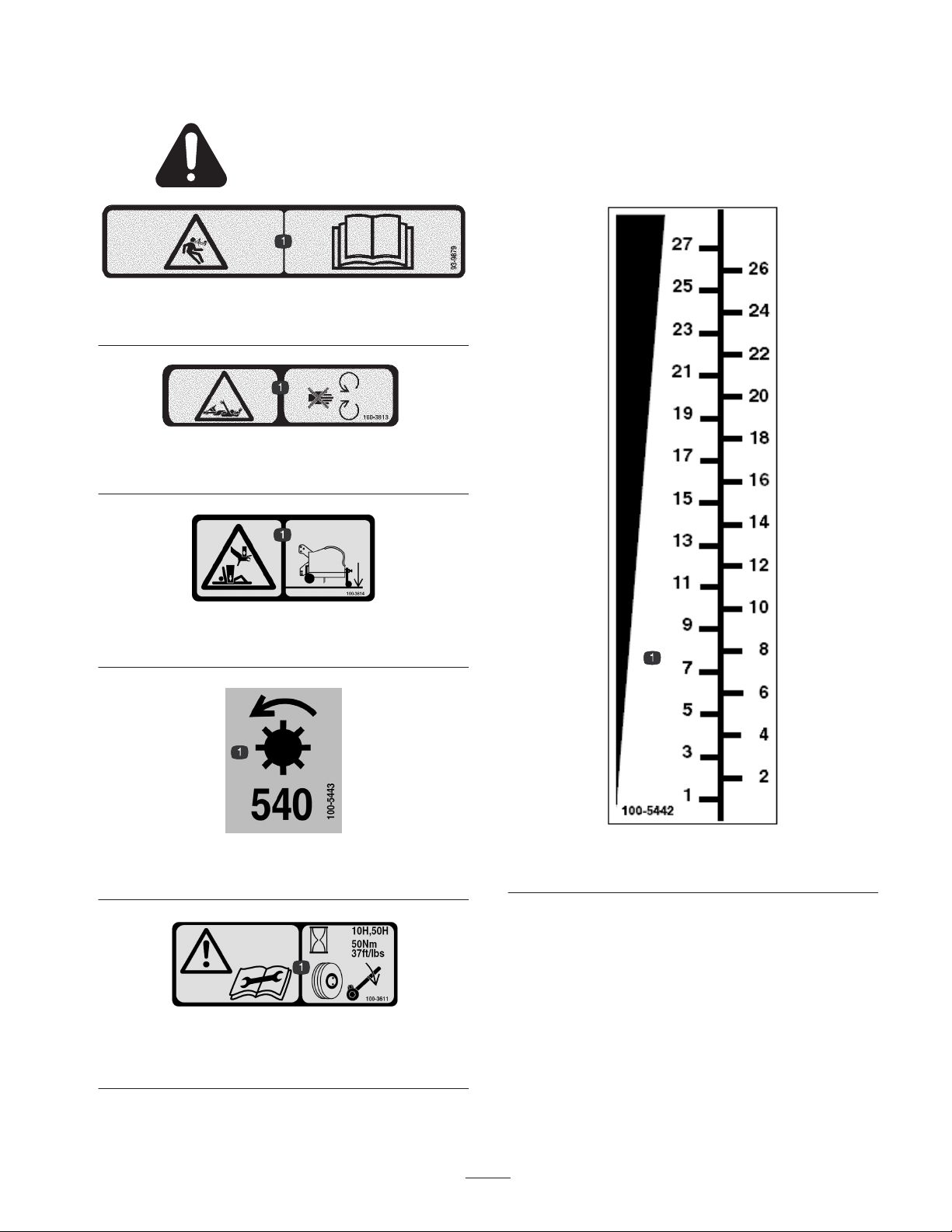
Safety and Instruction Decals
Safety decals and instructions are easily visible to the operator and are located near any
area of potential danger. Replace any decal that is damaged or lost.
93-9879
1. Stored energy hazard—read the Operator’s Manual.
100-3613
1. Full body entanglement hazard—stay away from moving parts
100-3614
1. Crushing hazard of hand and body—use the rear safety stand.
100-5443
1. PTO speed.
100-3611
1. Warning, read the Operator’s Manual—torque lug nuts to 37
ft-lbs (50 N⋅m) at intervals of 10 and 50 hours.
100-5442
1. Depth gauge.
5
Page 6
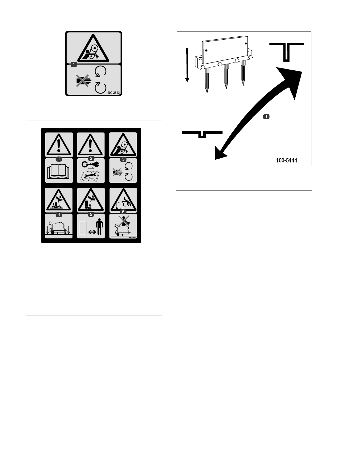
100-3612
1. Entanglement hazard—stay away from moving parts
100-3615
1. Warning, read the Operator’s Manual
2. Remove the ignition key and read the instructions before
servicing or performing maintenance.
3. Entanglement hazard—stay away from moving parts.
4. Crushing hazard of hand and body—lower machine to the
ground.
5. Crushing hazard of hand and foot—keep bystanders a safe
distance from the machine.
6. Falling hazard—do not carry passengers.
100-5444
1. Raise or lower to adjust depth height
6
Page 7

Specifications
General Specifications–660 Aerator
Working Width 60” (1.5 m)
Overall Width 72” (1.83 m)
Overall Length 33” (.84 m)
Overall Height 34” (.86 m)
Number of Tine Heads 6
Roller Diameter 6” (152 mm)
Weight 1,220 lbs. (554 Kg)
PTO Speed 540 rpm
Power Requirement 24 hp (17.5 Kw)
Hitch Category Category one, three point linkage
Min./Max. Depth 0” – 4” (0–105 mm)
Drive Belt Section 5VX (3) / Tine Pair
General Specifications–880 Aerator
Working Width 80” (2m)
Overall Width 92” (1.83 m)
Overall Length 33” (.84 m)
Overall Height 34” (.86 m)
Number of Tine Heads 8
Roller Diameter 6” (152 mm)
Weight 1,570 lbs. (640 Kg)
PTO Speed 540 rpm
Power Requirement 32 hp (23 Kw)
Hitch Category Category one, three point linkage
Min./Max. Depth 0” – 4.2” (0–105 mm)
Drive Belt Section 5VX (3) / Tine Pair
7
Page 8

Performance Specifications
mph
(km/hr)
0.6 (1) 1” (25 mm) 1.2” (30 mm) 2.4” (62 mm) 3.2” (81 mm) 15,385
0.8 (1.3) 1.5” (38 mm) 1.2” (30 mm) 2.4” (62 mm) 3.2” (81 mm) 23,008
1.1 (1.7) 2” (51 mm) 1.2” (30 mm) 2.4” (62 mm) 3.2” (81 mm) 30,769
1.4 (2.3) 2.5” (64 mm) 1.2” (30 mm) 2.4” (62 mm) 3.2” (81 mm) 38,531
1.7 (2.7) 3” (76 mm) 1.2” (30 mm) 2.4” (62 mm) 3.2” (81 mm) 46,015
2.0 (3.2) 3.5” (89 mm) 1.2” (30 mm) 2.4” (62 mm) 3.2” (81 mm) 53,777
2.2 (3.5) 4” (102 mm) 1.2” (30 mm) 2.4” (62 mm) 3.2” (81 mm) 61,261
2.5 (4) 4.5” (114 mm) 1.2” (30 mm) 2.4” (62 mm) 3.2” (81 mm) 69,300
Note: Performance specifications shown are maximum values obtained at rated (540 rpm) PTO speed. Changing engine /
PTO rpm in any particular gear (or fixed hydrostatic pedal position) will not change forward hole spacings, although mph
and productivity specifications will be proportionately changed.
Forward
Hole
Spacings
Lateral Hole
Spacing
Mini Tine
Lateral Hole
Spacing
4 Tine Head
Lateral Hole
Spacing
3 Tine Head
Sq. ft. / Hr.
(Sq. m / Hr.)
660
(1,403)
(1,877)
(2,858)
(3,579)
(4,274)
(4,995)
(5,690)
(6,437)
Sq. ft. / Hr.
(Sq. m / Hr.)
880
20,513
(1,871)
30,677
(2,503)
41,025
(3,811)
51,375
(4,772)
61,353
(5,699)
71,703
(6,660)
81,681
(7,587)
92,400
(8,583)
8
Page 9
Setup
Note: Determine the left and right sides of the machine from the normal operating position.
Loose Parts Chart
Note: Use this chart as a checklist to ensure all parts necessary for assembly have been shipped. If any of these parts are
missing, total setup cannot be completed.
Description Qty. Use
PTO drive shaft 1 Transfers power from tractor to aerator
Rear castor/safety shield 1 Support aerator for maintenance/storage
Side guards 2 Keeps hands and feet away from tines
Keys 2 For hood latch on TE models
Operator’s Manual 2 Read before operating machine
Parts Catalog 1 Service part identification
Tractor Requirements
• 24 horsepower—660
• 32 horsepower—880
• Correct tire pressure
• Category one 3 point hitch, rated to lift at least a
1400 lb. (637 Kg) implement–660
• Category one 3 point hitch, rated to lift at least a
1700 lb. (771 Kg) implement–880
• 540 rpm tractor PTO
• Adequate front-end weight (ballast)
Ballast Requirements
Caution
To help prevent bodily injury and provide added
stability, make sure front of the tractor is
equipped with proper ballast. Refer to tractor
operator’s manual for ballast requirements.
• Refer to Tractor Operator’s Manual for ballast
requirements.
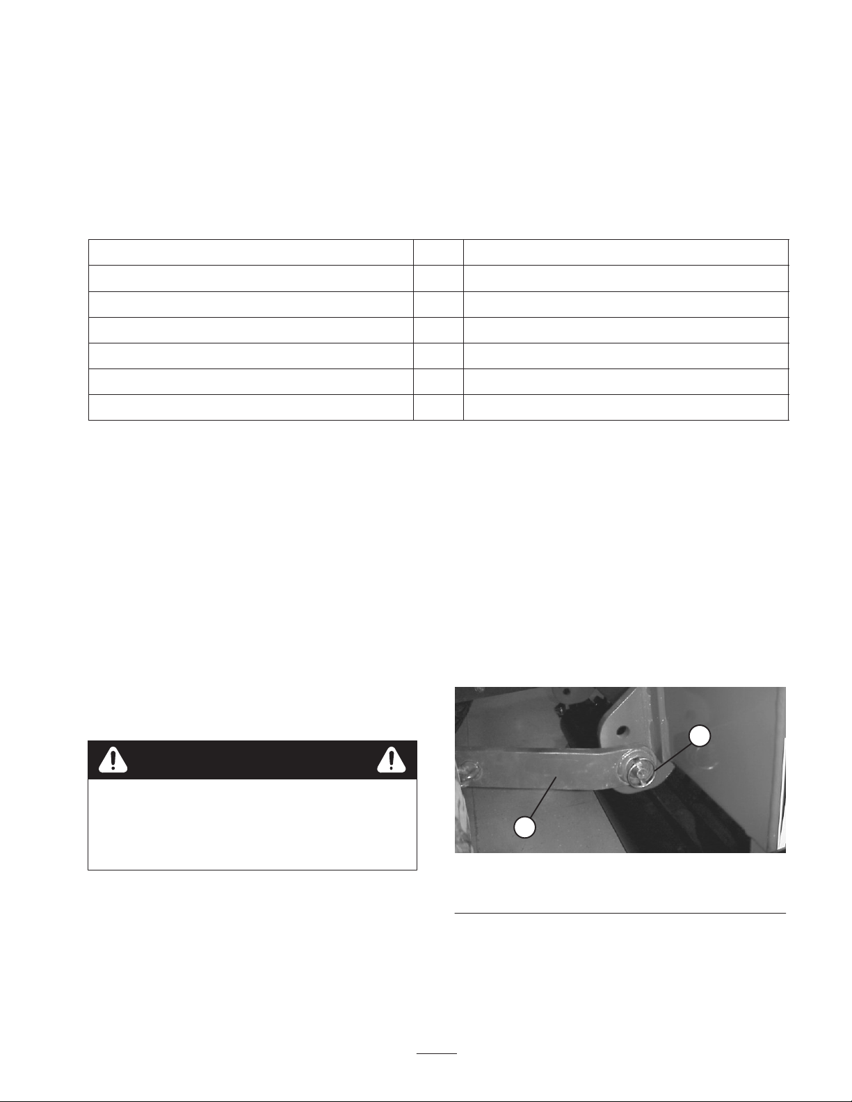
Connect Lower Link Arms
1. Aerator must be positioned on a flat, level surface for
installation.
2. Back tractor squarely up to aerator until lower link
arms are aligned with hitch pins.
3. Make sure PTO is disengaged.
4. Engage parking brake, STOP engine and remove key
from ignition. Wait for engine and all moving parts to
STOP before leaving operator’s seat on tractor.
5. Insert right and left lower link arms onto hitch pins
(Fig. 2).
2
1
Figure 2
1. Lower link 2. Lynch pin
6. Secure lower link arms to hitch pins with lynch pins
(Fig. 2).
9
Page 10

Connect Upper Link
Install Side Guards
Note: Front of aerator must be vertical or angle forward
slightly while operating for best aeration hole quality
(Fig. 3).This angle will change when depth adjustments
are made. Adjust upper link to control this angle. Refer to
Operation, page 17 for additional information.
0–8_
Operating
Range
90_
Figure 3
1. Connect upper link to lower hole in bracket and secure
with link pin and lynch pin (Fig. 4).
1
1. Remove 4 nuts, lockwashers and washers loosely
secured to each bottom end of aerator frame.
2. Position appropriate side guard (left or right) onto
mounting studs (Fig. 5).
1
Figure 5
1. Side guard (LH)
2
3
Figure 4
1. Upper link
2. Link pin
2. Rotate adjusting link to tighten the link. Do not
overtighten to raise the back end of the aerator off the
ground.
3. Tighten lock nut to secure upper link into position.
3. Lynch pin
3. Secure each side guard to mounting studs with washers
and nuts previously removed.
Adjust PTO Shaft Length
Important A long PTO shaft is supplied with machine
to accommodate large variations in the tractor’s PTO and
3 point locations. For most tractors this shaft is too long
and must be cut to correct length or gearbox damage may
result.
1. With the aerator vertical or angled slightly forward,
lower the aerator until the gear box shaft is
approximately the same height as the tractor PTO
shaft. This is the shortest distance between the two
shafts.
2. Measure the distance from the lock groove of the
tractor PTO shaft to the lock groove of the aerator
gearbox PTO shaft. Record this dimension.
3. Fully collapse PTO shaft and measure the distance
between the lock pin collars. Record this dimension.
4. At it’s shortest length, the two halves of the PTO shaft
must have at least 1.5 inches (37 mm) of additional
clearance to collapse (Fig. 6). If the dimension in step
2 is not at least 1.5 inches (37 mm) greater than the
10
Page 11

dimension in step 3, the PTO shaft is too long, proceed
to step 5. If there is enough clearance to allow PTO
shaft to collapse, proceed to step 10.
1
1.5”
(37 mm)
Figure 6
1. PTO shaft
Connect PTO Shaft
1. Connect PTO shaft to gearbox input shaft (Fig. 7).
2
1
5. Use the following calculation to establish how much
shorter the shaft must be, when connected, to ensure a
clearance of 1.5 inches (37 mm).
A. Subtract the dimension recorded in step 3 from the
dimension recorded in step 2. Record this
dimension.
B. Subtract the result in step 5A from 1.5” (37mm).
The PTO shaft must be shortened by this amount.
6. Using a hacksaw, cut the yellow guards and the steel
tubes shorter by the calculated length. Cut both halves
of the PTO shaft
7. Deburr ends of steel tubes internally and externally.
8. Remove all debris from tube sections.
9. Grease steel tubes liberally.
10. Assemble PTO shaft and secure to aerator and tractor.
11. Measure the shaft. If not at least 1.5 inches (37 mm),
repeat procedure.
12. Raise aerator to highest position. There must be at
least 3 inches (75 mm) of overlap of the halves. Adjust
3 point lift stop, if necessary. Refer to Adjust 3 Point
Lift Stop, page 11.
Figure 7
1. PTO shaft 2. Safety chains
2. Connect PTO shaft to rear tractor PTO shaft.
3. Slide PTO shaft forward as far as it will go.
4. Depress pin to secure PTO shaft in place. Slide PTO
shaft back and forth to make sure it is properly locked.
5. Connect shield safety chains from powershaft sections
to welded clips on link arms or to PTO shields. Make
sure chains remain slack when aerator is raised or
lowered.
Caution
To help prevent bodily injury, keep all PTO
shields in place and connect shield chains to link
arms or PTO shields to prevent shields from
rotating during operation.
11
Page 12

Mount Castor/Safety Stand
Note: Use castor wheel to move aerator around on a hard
surface, as aligning to tractor for installation or for
storage. Level aerator by adjusting roller until the point of
the depth adjustment arrow is just above the side guards.
1. Remove bolt and nut securing rear castor/safety stand
tube to shipping pallet (Fig. 8). Retain bolt and washer
for installation of castor wheel.
2
1
Figure 8
1. Shipping pallet 2. Castor/safety stand
2
1
Figure 10
1. Pin 2. Castor knob
2. Raise aerator off pallet.
3. Remove pallet.
4. Mount castor wheel to rear castor/safety stand tube
with bolt and washer previously removed (Fig. 9).
2
1
Figure 9
1. Castor wheel 2. Castor/safety stand
5. Rear castor/safety stand has two positions:
• Collapsed for aerator storage
• Extended for aerator maintenance
7. Slowly lower aerator to the ground.
Adjusting Sway Links
Adjust sway links on lower draft arms of 3-point hitch to
minimize side-to-side sway to a maximum of 1 inch
(25 mm) on each side (Fig. 11).
1
Figure 11
1. Sway link
6. Secure castor/safety stand in desired position with pin
(Fig. 10). Tighten castor knob.
1. Adjust the lower links inboard until they contact the
aerator mounting plates. This will reduce the stress on
the pins. If the tractor has sway chains instead of sway
12
Page 13

links, it is recommended that washers be installed
between the lower link arm and lynch pin to reduce the
over hung load on the lift pins.
Note: Refer to tractor operator’s manual for additional
installation and adjustment procedures.
Level Aerator Side–to–side
1. Park tractor and aerator on a level, firm surface. Make
sure both depth gauges are set at the same setting.
2. Place level on top of aerator hood to check for level
side-to-side (Fig. 12).
1
1
Figure 12
1. Level 2.
3. Turn the adjustable link body (if provided) to raise or
lower the link arm until the aerator is leveled
side–to–side.
Note: Refer to tractor operator’s manual for additional
adjustment procedures.
Adjust 3-Point Lift Stop
Adjust and set 3 point lift stop (Fig. 13) to provide
approximately 4” ground clearance, when in the raised
position, to minimize PTO angle when raising aerator. For
transporting or trailer loading/unloading, the full lift range
can be used as long as the PTO tubes do not slide apart.
Operating the PTO in the fully raised position may
damage the PTO or other components.
Figure 13
1. 3-Point lift stop
Note: Refer to tractor operator’s manual for adjustment
procedures.
Install Tines/Tine Heads
A wide selection of tines and tine heads are available for
the aerator. Choose the tine type, size and spacings
required for the job. Install the tine head and tines per
Installation Instructions supplied with each tine kit. Refer
to accessory chart on page 13, for required tines.
Important Never operate the aerator without the
tine heads installed. The arms will move excessively
and may damage the aerator frame.
13
Page 14

Mount Turf Guards
A wide selection of turf guards are available for the
aerator. Choose the required turf guards per accessory
chart on page 13.
1. Loosen nuts securing turf guard clamps to turf finger
tool bar (Fig. 14).
5
2
3
4
2
1
Figure 14
1. Turf guard
2. Turf finger tool bar
3. Turf guard clamp
4. Notch
5. Locator key
2. Slide appropriate turf guard under center turf guard
clamp while inserting notch onto locator key of turf
finger bracket (Fig. 14). Refer to accessory chart note,
page 13.
3. Tighten nuts securing turf guard and center turf guard
clamp to turf finger bracket.
4. Working outward, mount remaining turf guards to each
side and secure turf guard clamps.
Important From the rear of the machine, check that
the tines line up with the center of the gaps in the turf
guards.
5. To decrease down pressure of turf guards:
A. Remove nuts securing each end of turf finger
bracket to roller legs (Fig. 15).
1
Figure 15
1. Spacer location ( 1 each
end)
2. Roller scraper tab
B. Pivot turf finger bracket upward and insert a
washer onto each stud.
C. Pivot turf finger downward onto studs and check
angle.
D. Install nuts to secure assembly.
Note: Aeration depth may need to be reduced to ensure
clearance between the tine heads and the turf guards.
Check clearance before aerating.
Note: To aid in the loading/unloading of the aerator from
a trailer, remove nuts securing each end of turf finger tool
bar to roller legs and pivot turf finger tool bar upward.
Adjust Roller Scraper
Adjust roller scraper so there is approximately a 1/8”
(3mm) gap between scraper and roller.
1. Loosen fasteners securing each end of scraper to roller
scraper tab (Fig. 14).
2. Slide the roller scraper up or down to required position
and tighten fasteners.
14
Page 15

Adjust Turf Guards
Before starting your new aerator, remove the rear castor
stand and lower the machine on the 3–point linkage until
the depth control roller is resting on the ground. From the
rear of the machine, check that the tines line up exactly
with the center of the gaps in the turf guards. Install the
correct turf guards (Fig. 16), if necessary.
Figure 16
9. Loosen locking nut and rotate adjusting link to release
tension between aerator and tractor.
10. Remove lynch pin and top link pin securing center link
to bracket.
11. Push release pin to disconnect powershaft from tractor
PTO shaft.
12. Slide powershaft back and remove from tractor.
13. Remove lynch pins and slide lower link arms off hitch
pins.
Note: Turf with a good root structure may not require the
turf guards. If this is the case. Do not remove the turf
guard tool bar as this adds support to the roller leg
assembly. Just remove the plastic fingers from the turf
guard bracket.
Removing Aerator from Tractor
1. Stop vehicle on a level surface, not on a slope.
2. Disengage the PTO and engage the parking brake.
3. Stop the engine and remove the key from ignition
switch.
4. Before leaving the operator’s seat on tractor, wait for
engine and all moving parts to stop.
5. Install rear castor/safety stand, collapse it to storage
position and install pin. Tighten knob.
Note: Aerator can be stored on original shipping pallet if
desired. Remove castor wheel.
6. Disconnect safety shield chains from PTO tractor.
Secure end of chain to aerator side of PTO shaft to
prevent PTO shaft from coming apart.
7. Slowly lower aerator until rear castor/safety stand
contacts ground.
8. Lower roller, by adjusting depth control handles, until
roller contacts ground.
15
Page 16

Accessory Chart
4 Tine Head
(2.4” spacing)
3 Tine Head
(3.2” spacing)
Duty Head
4 Tine Heavy
(2.4” spacing)
ProCore 600 Aerator
Model Number 09701
Model Number 09701TE
6 Required
Model No. 09723
6 Required
Model No. 09722
6 Required
Heads Required
Model No. 09734
5 x #100-5416
Turf Guards Required
2 x #100-5414
3 x #100-5415*
Turf Guards Required
5 x #100-5416
Turf Guards Required
Tines Required
Tines Required
Tines Required
24 Required
18 Required
24 Required
Tine Options
.35” (9 mm) Solid Tine=#100-3626
.43” (11 mm) Solid Tine=#100-3628
.39” (10 mm) Solid Tine=#100-3627
Side Eject
Tine Options
.83” (21 mm)
Tine=104-9877
.51” (13 mm) Solid Tine=#100-3629
.63” (16 mm) Solid Tine=#100-3630
.51” (13 mm) Hollow Tine=#100-3634
.63” (16 mm) Hollow Tine=#100-3635
.63 (16 mm) HD Side Ejection Hollow
.39” (10 mm) Hollow Tine=#100–3633
Hollow
.75” (19 mm)
Side Eject
.75” (19 mm)
Tine=86-9720
Tine=104-9876
Tine=#104-9875
.75” (19 mm) HD Side Ejection Hollow
Tine=92-7900
Duty Head
3 Tine Heavy
(3.2” spacing)
Head
8 Mini Tine
(1.2” spacing)
Head
6 Needle Tine
(1.6” spacing)
6 Required
Model No. 09733
6 Required
Heads Required Heads Required Heads Required Heads RequiredHeads Required
Model No. 09721
6 Required
Heads RequiredHeads Required
Model No. 09720
2 x #100-5414
3 x #100-5415*
Turf Guards Required
8 x #100-5421
1 x #100-5420*
Turf Guards Required
6 x #100-5418
1 x #100-5419*
Turf Guards Required
Note: One of these turf guards must be installed in center position.
16
18 Required
Tines Required
48 Required
Tines Required
36 Required
Tines Required
Mini Solid
Tine Options
.37” (9.5 mm)
Tine=100-3622
Needle
.20” (5 mm)
Tine Options
Tine=100-3620
Side Eject
.25” (6.5 mm)
.31” (8 mm)
.20” (5 mm)
Tine=94-3417
Needle
Tine=100-3621
Mini Side Eject
Tine=100-3625
Page 17

Accessory Chart
4 Tine Head
(2.4” spacing)
3 Tine Head
(3.2” spacing)
Duty Head
4 Tine Heavy
(2.4” spacing)
ProCore 880 Aerator
Model Number 09702
Model Number 09702TE
8 Required
Model No. 09723
8 Required
Model No. 09722
8 Required
Heads Required
Model No. 09734
4 x #100-5417
1 x #100-5416*
Turf Guards Required
5 x #100-5414
Turf Guards Required
4 x #100-5417
1 x #100-5416*
Turf Guards Required
Tines Required
Tines Required
Tines Required
32 Required
24 Required
32 Required
Tine Options
.35” (9 mm) Solid Tine=#100-3626
.43” (11 mm) Solid Tine=#100-3628
.39” (10 mm) Solid Tine=#100-3627
Side Eject
Tine Options
.83” (21 mm)
Tine=104-9877
.51” (13 mm) Solid Tine=#100-3629
.63” (16 mm) Solid Tine=#100-3630
.51” (13 mm) Hollow Tine=#100-3634
.63” (16 mm) Hollow Tine=#100-3635
.63 (16 mm) HD Side Ejection Hollow
.39” (10 mm) Hollow Tine=#100–3633
Hollow
.75” (19 mm)
Side Eject
.75” (19 mm)
Tine=86-9720
Tine=104-9876
Tine=#104-9875
.75” (19 mm) HD Side Ejection Hollow
Tine=92-7900
Duty Head
3 Tine Heavy
(3.2” spacing)
Head
8 Mini Tine
(1.2” spacing)
Head
6 Needle Tine
(1.6” spacing)
8 Required
Model No. 09733
8 Required
Heads Required Heads Required Heads Required Heads RequiredHeads Required
Model No. 09721
8 Required
Heads RequiredHeads Required
Model No. 09720
5 x #100-5414
Turf Guards Required
4 x #100-5421
5 x #100-5420*
Turf Guards Required
7 x #100-5419
Turf Guards Required
Note: One of these turf guards must be installed in center position.
17
24 Required
Tines Required
64 Required
Tines Required
48 Required
Tines Required
Mini Solid
Tine Options
.37” (9.5 mm)
Tine=100-3622
Needle
.20” (5 mm)
Tine Options
Tine=100-3620
Side Eject
.25” (6.5 mm)
.31” (8 mm)
.20” (5 mm)
Tine=94-3417
Needle
Tine=100-3621
Mini Side Eject
Tine=100-3625
Page 18

Controls
Depth Adjustment Handles
Remove lynch pins, rotate handles to raise or lower tines
to desired depth and replace lynch pins (Fig. 17).
1
2
Figure 17
1. Depth adjustment handle 2. Lynch pin
Depth Guides
Depth guides (1 thru 27) are provided to give equal
increments for adjustment. The numbers do not relate to
measurements of depth as this changes with tine type and
amount of tine wear. Adjustment between two numbers
will give approximately .20 inches (5 mm) change in
depth. The higher the number, the deeper the tine
penetration. Always adjust each side to the same number
(Fig. 18).
1
Figure 18
1. Depth guide
18
Page 19

Operation
Adjust Tine Depth
To adjust the working depth of the tine, proceed as
follows:
1. Remove the lynch pin from each depth adjust handle
(Fig. 19).
1
Figure 19
1. Depth adjustment handle
1
Figure 20
1. Depth guide
Important If a large change in height is required,
adjust each leg by a small amount to ensure the roller legs
are adjusted as evenly as possible.
Note: Remember when depth changes are made, you will
need to adjust the top link length to give the correct
machine angle. Refer to Connect Upper Link, page 8.
Important Tine depth is affected by the mounted
angle of the aerator as well as the depth setting. If the
aerator is angled rearward, the tine heads may contact the
turf guards and damage may occur. Depths 26 & 27
cannot be used when the aerator is in the vertical position.
See Depth Chart.
2. Turn the depth adjuster handles to raise (deeper) or
lower (shallow) the roller.
Note: Make sure that the roller is on the ground once the
depth is chosen.
3. Depth guides (Fig. 20) are provided with numbers 1
through 27. Depth varies with the mounted angle of
aerator, tine type and amount of tine wear. Refer to
Depth Chart on page 16. Adjustment between two
numbers will give approximately 0.20 inches (5 mm)
change in depth. The higher the number, the deeper the
tine penetration. Always adjust each side to the same
number.
4. Install the depth adjust handle lynch pins before
running the machine, even if you are just testing for
correct depth.
Important Tine depth is determined by the tine type,
depth adjustment, amount of tine wear and mounted angle
of the aerator. Refer to Depth Chart on page 18.
Important Maximum depth is achieved when the
aerator is mounted vertically (Fig. 21) and the depth
adjustment set at 25. In this condition, do not operate at
greater depth settings, as there is minimal clearance
between the tine head and the turf guards. Never operate
with the aerator angled rearward or damage to the turf
guards may occur.
19
Page 20

Figure 21
4_
90_
“H1”
“H2”
In some instances, angling the aerator forward may
improve hole quality but will also reduce aeration depth
and gain clearance with the turf guards. A forward angle
of approximately 4_ is a good initial setting. Use a
magnetic based angle indicator to determine the forward
angle, or use the following procedure:
A. Position aerator on a flat level surface.
B. Make sure aerator roller is on the ground and depth
indicator is set at desired setting (Fig. 22).
1
Figure 23
D. Adjust upper link until the difference between
“H1”–“H2” matches desired forward angle of
aerator (See Angle Chart below).
“H1”–
“H2”
Angle 0_
0” 0.8”
(21mm)
2_ 4_ 6_ 8_
1.7”
(43mm)
2.5”
(64mm)
3.3”
(85mm)
Figure 22
1. Depth guide
C. Measure and record the distance from the ground
to the lower rear corner of the frame (“H1”) and
front corner of the frame (“H2”) (Fig. 23).
20
Page 21

Depth Chart Guide
Note: In instances where sufficient root growth exists, the turf guards may be removed to attain maximum depth without
damaging the turf guards.
Note: For future reference, record the upper link length
that achieves the desired operating angle.
• Gear Selection
Note: Refer to tractor operator’s manual for operating
instructions.
Tractor Controls
It is necessary to familiarize yourself with the operation of
the following tractor controls before you are able to
operate the aerator:
• PTO Engagement
• 3-Point Hitch (Raise/Lower)
• Clutch
• Throttle
Principles of Operation
The tractor’s three point hitch linkage lifts the aerator for
transport and lowers it for operation.
The tractor’s power take-off (PTO) power is transmitted
via shafts, gearbox and drive belts to a number of
crankshafts which drive the tine holding arms into the turf
surface.
21
Page 22

As the tractor travels forward with the PTO engaged and
the machine lowered, a series of holes are created in the
turf surface.
The depth of the tine’s penetration is determined by the
mounted angle of the aerator and the height of the depth
control roller.
The distance between the holes created is determined by
the tractor’s gear ratio (or hydrostatic traction pedal
position) and the number of tines in each tine head.
Simply changing engine rpm does not change hole
spacing.
Training Period
Before using the aerator, find a clear area and practice
using the machine. Operate the tractor at recommended
gear settings and PTO drive speeds and become
thoroughly familiar with machine handling. Practice
stopping and starting, raising and lowering the aerator,
disengaging the PTO drive and aligning the machine with
previous passes. A practice session assures confidence in
the performance of the Aerator and helps ensure use of
proper operating techniques wherever the machine is
operated.
If there are sprinkler heads, electrical or communication
lines or other obstructions in the area to be aerated, mark
these items to ensure they are not damaged during
operation.
Caution
To avoid personal injury, never leave the tractor
seat without first setting the parking brake and
disengaging the PTO drive. Never perform
aerator repairs without first lowering the aerator
onto the castor/safety stand. Be sure all safety
devices are secured in proper place before
resuming operation.
Before Aerating
Inspect the area of operation for hazards that could
damage the machine and remove them, if possible, or plan
how to avoid them. Carry replacement tines and tools to
effect repairs should tines contact foreign materials.
2. At a low tractor engine rpm, engage the power take off
(PTO) clutch to start the aerator working.
Important Do not operate aerator at 540 PTO rpm
when lifted out of the ground. This machine can be
damaged if operated at full speed without the tines
working in the turf. Never operate aerator without tine
heads installed
3. Select a gear that gives a forward speed of
approximately .6 – 2.5 MPH (I to 4 km/hr) at (refer to
tractor operator’s manual) rated PTO speed.
4. As the clutch is released and the tractor moves
forward, lower the machine fully into work and
increase engine speed to give a maximum of 540 rpm
at the PTO.
Important Never operate the tractor PTO in excess of
540 rpm or damage to the aerator could occur.
Note: Make sure that the roller is on the ground.
5. Note the hole pattern. If you require greater hole
spacing increase forward speed of the tractor by
changing up a gear or with a hydro–static drive tractor,
shift the hydrostat lever or pedal to give faster speed.
For closer hole spacing, decrease tractor forward
speed. Changing engine speed, in a particular gear,
will not change the hole pattern. Operate at an
engine speed that the aerator runs smoothly.
Important Look behind frequently to ensure the
machine is operating properly and alignment is
maintained with previous passes.
6. Use the front tractor wheel as a guide to maintain
equal lateral hole spacing with the previous pass.
7. At the end of the aeration pass, raise the aerator, lower
the engine rpm and disengage the PTO.
8. If you back into a tight area (like a tee box), disengage
the PTO and raise the aerator to it’s highest position.
Use caution not to catch the turf guards on the turf.
9. Always clear the area of all damaged machine parts,
such as broken tines, etc., to prevent their being picked
up by mowers or other turf maintenance equipment.
10. Replace broken tines, inspect and correct damage to
those still useable. Repair any other machine damage
before commencing operation.
Transport Operation
Aerating Procedures
Note: When using needle tine heads, make sure to read
instructions, included with kit, for unique operating
procedure.
1. Lower the aerator on the 3–point linkage so that the
tines are nearly to the ground at the lowest part of their
stroke.
To begin transport operation, raise the aerator and
disengage the PTO. To avoid loss of control, traverse
steep inclines slowly, approach rough areas at reduced
speed and cross severe undulations carefully.
Important Do not exceed transport speeds of 15 mph
(24 km/hr).
22
Page 23

Caution
Do not exceed the maximum or minimum tractor
tire inflation pressures as recommended by tire
manufacturer.
Inspection and Cleanup after
Use
After daily use, thoroughly wash the machine with a
garden hose without a nozzle so contamination and seal
and bearing damage due to excessive water pressure will
be avoided. A brush may be used to remove caked-on
material. Use mild detergent to clean the covers. Applying
a coat of auto wax periodically will retain the cover’s
glossy finish. After cleaning, inspect for machine
damage, gear oil leakage, component and tine wear.
7. Always check/adjust top link whenever aeration depth
is changed. The front of the aerator should be vertical
or angled slightly forward. Experiment with depth and
angle to achieve best hole quality.
Note: Once optimum hole quality is attained, record depth
setting and the upper link length for future reference.
Caution
To avoid personal injury, never leave the tractor
seat without first setting the parking brake and
disengaging the PTO drive. Never perform
aerator adjustments or repairs without first
lowering the aerator onto the castor/safety stand.
Be sure all safety devices are secured in proper
place before resuming operation.
Optional Core Windrower
Operating Tips
1. Gradually engage PTO at low engine speed while
increasing throttle to 540 PTO rpm (maximum) while
lowering aerator. Operate at an engine rpm that the
aerator runs most smoothly.
Note: Changing engine / PTO rpm in a particular tractor
gear (or fixed hydrostatic pedal position on tractors with
hydrostatic transmission) will not change forward hole
spacing.
Important Do not operate PTO at high rpms for
extended time periods when aerator is out of the
ground.
2. Make very gradual turns when aerating. Never make
sharp turns with PTO drive engaged. Plan your
aeration path before lowering the aerator.
3. If tractor “bogs” down when operating on hard ground
or going uphill, raise aerator slightly until speed is
regained, then lower aerator again.
4. Do not aerate if ground is too hard or dry. Best results
are obtained after a rain or when turf has been watered
the previous day.
Note: If the roller rides up off the ground while aerating,
the ground is too hard to achieve the desired depth, reduce
the aeration depth until the roller contacts the ground
during operation.
ProCore 660 only
When using hollow tines, an Optional Core Windrower
(Toro Model No. 09732) is available to place cores in
narrow rows behind the machine.
Optional Contour Following Kit
An Optional Contour Following Kit (Toro Model No.
09154) is recommended for aeration on undulating or
uneven surfaces.
5. Raise aerator penetration, if ground is hard packed.
Clean–up cores and re–aerate at deeper penetration,
preferably after watering.
6. The aerator is offset to one side to allow aerating
without driving over the cores with the tractor tires.
Whenever possible, aerate with the longer offset
towards the previous aeration pass.
23
Page 24

Maintenance
Lubrication
Greasing Bearings and Bushings
The main working bearings of the aerator are sealed for
life and require no maintenance or lubrication. This
drastically reduces the maintenance required and
eliminates the risk of grease or oil being dropped onto the
turf.
There are grease fittings that must be lubricated with an
SAE multi–purpose, high–temperature grease with high
pressure (EP) performance or SAE multi–purpose lithium
base grease.
The lubrication intervals and points are:
Lubricate Daily–PTO shaft (3) (Fig. 24).
Figure 26
Figure 27
Figure 24
Lubricate Weekly–Roller Bearings (2) (Fig. 25), Depth
Jacks (2) (Fig. 26), Drive Shaft Bearings (2) (Fig. 27).
Gearbox Lubrication
The gearbox is filled with 85/140 gear oil or equivalent.
Check gearbox oil level every 6 months or 100 hours.
1. Remove check plug at rear of gearbox (Fig. 28).
2
1
Figure 28
1. Check plug 2. Fill plug
2. Make sure oil is up to bottom of check plug hole in
gearbox (Fig. 28).
Figure 25
3. If oil level is low, remove fill plug on top of gear box
and replenish oil as required.
4. Install plug.
24
Page 25

Torque Taper Lock Assembly
After first 10 hours of operation torque set screws securing
taper lock bushings to driven pulleys to 37 ft. lbs.
(50 N⋅m) (2 each pulley) (Fig. 29).
6. Install setscrews in taper lock bushing and secure.
Torque setscrews in an alternating method to 37 ft–lbs
(50 Nm).
7. Remove M12 bolt and replace the assembly washer
with original ”thin” washer. Re–torque M12 bolt to
59–73 ft–lbs (80–100 Nm).
8. Re–install belt tension.
1
2
Figure 29
1. Bushing set screws 2. Bolt (M12)
Every 50 hours of operation, perform the following
maintenance procedure to ensure proper bearing clamp
load. Failure to perform this maintenance procedure can
lead to premature failure of crank shaft assembly resulting
in an extensive repair.
Note: An upgraded crank assembly is available after
January 1, 2005 that does not require this maintenance
procedure. See your Toro distributor for further
information.
1. Remove belt tension from crank assembly.
2. Position stomper arm on pulley side of crank assembly
at bottom dead center.
3. Remove M12 bolt securing the taper lock assembly to
the opposing crank arm (Fig. 29)
4. Remove taper lock bushing set screws from bushing.
Install set screws in the removal holes and tighten until
taper lock bushing is free from pulley. Remove
setscrews from removal holes.
5. Use the ”thick” assembly washer located in the frame
under the bolt that holds the manual tube and torque
the M12 bolt to 59–73 ft–lbs (80–100 Nm).
Torque Jackshaft Set Screws
After first 10 hours of operation and every 50 hours
thereafter, torque set screws securing drive shafts to gear
box shafts to 20–25 ft. lbs. (26–32 N⋅m) (4 each side)
(Fig. 30).
1
1
Figure 30
1. Drive shaft set screws
Adjusting Belt Tension
Make sure belts are properly tensioned to ensure correct
operation of unit and unnecessary wear.
1. Proper belt tension is attained by compressing idler
spring to a length of 3 inches (76 mm).
2. To adjust belt tension, proceed as follows:
A. Loosen jam nut securing idler tube to tensioner arm
(Fig. 31).
25
Page 26

B. Rotate hex on top of idler tube until the bottom of
the rubber boot is between the two grooves in the
guide tube. At this position the spring will be
compressed to a length of 3 inches (76 mm).
5
7
4
2
C. Tighten jam nut.
1
6
3
1
2
3
Figure 32
1. Idler spring boot
2. Jam nut
3. Adjusting nut
4. Idler pin & hairpin cotter
5. Idler pulley
6. Hairpin cotter & idler shaft
7. Tine arm assembly
4. Remove hair pin cotter securing idler pulley assembly
to idler shaft (Fig. 32). Remove idler assembly from
shaft.
4
5. Remove screw, lock washer and flat washer securing
top of tine arm to pulley (Fig. 32).
6. Remove fasteners securing bottom of tine arm or
rotalink arm to bottom links (Fig. 33). Align tine arm
with slot in frame and slide off crank pin.
Figure 31
1. Idler spring boot
2. Jam nut
3. Idler tube
4. Bottom guide tube groove
Replacing Belts
1. Loosen jam nut securing idler tube to tensioner arm
(Fig. 32).
2. Rotate hex on top of idler arm until all spring tension
is removed (Fig. 32).
Caution
Springs are under tension, use caution when
adjusting or removing.
3. Remove hair pin cotter and idler pin securing top of
spring assembly to frame (Fig. 32).
1
3
2
Figure 33
1. Tine arm
2. Bottom link
3. Rotalink arm
7. To ensure components are re–installed correctly, mark
location of end cover on aerator frame (Fig. 34)
26
Page 27

8. Remove (8) capscrews and flat washers securing end
cover and bearing housing to end of aerator frame
(Fig. 34).
1
Figure 34
1. End cover
13. Route new belts over drive shaft and onto pulleys.
14. Reinstall end cover onto drive shaft. At location
marked on frame, loosely secure end cover to aerator
frame with (8) capscrews and flat washers removed.
15. Reinstall bottom of tine arm to bottom links or rotalink
arm with fasteners removed.
16. Reinstall top of tine arm to pulley with screw, lock
washer and flat washer.
17. Secure idler pulley assembly to idler pivot shaft with
hair pin cotter.
18. Secure top of spring assembly to frame with idler pin
and hair pin cotter.
19. Adjust belt tension. Refer to Adjusting Belt Tension.
Storage
9. Loosen bearing set screws (Fig. 35).
1
Figure 35
1. Bearing
10. Remove end cover and bearing.
Note: Remove only the end cover necessary to access
belts being removed, i.e.
Model 660
Left cover – Left belts
Right cover – Center and Right belts
At the end of an aerating season or when the aerator will
not be used for a long period, it is good practice to carry
out the following preventative maintenance.
1. Clean off any dirt or grease that may have
accumulated on the aerator or any of the moving parts.
2. Remove the tines and clean out hollow tines. Coat
tines with oil to prevent rusting during storage.
3. Open the hood and clean out the inside of the machine.
4. Lubricate all grease fittings.
5. Store the machine with the roller and castor wheel
standing on a hard, dry surface or board and block the
roller.
6. Remove PTO drive shaft and store under hood
7. Paint the roller and touch–up any other scratches on
the paintwork.
8. Replace any missing or damaged decals.
9. Store the aerator inside a dry secure building. Inside
storage will reduce maintenance, give a longer
working life and increase the residual value of the
machine. If inside storage is not available, cover with
a heavy sheet or tarpaulin and secure tightly.
Model 880
Left cover – Left & left center belts
Right cover – Right and Right center belts
11. Slide belts off driven and driver pulleys.
12. Remove belts from aerator by routing them over drive
shaft, thru holes in frame center plates, over bearings
and out hole in end of frame.
Important When changing belts, always change all (3)
belts on the pulley.
27
Page 28

The Toro General Commercial Products Warranty
A Two-Year Limited Warranty
Conditions and Products Covered
The Toro Company and its affiliate, Toro Warranty Company,
pursuant to an agreement between them, jointly warrant your Toro
Commercial Product (“Product”) to be free from defects in
materials or workmanship for two years or 1500 operational
hours*, whichever occurs first. Where a warrantable condition
exists, we will repair the Product at no cost to you including
diagnosis, labor, parts, and transportation. This warranty begins
on the date the Product is delivered to the original retail purchaser.
* Product equipped with hour meter
Instructions for Obtaining Warranty Service
You are responsible for notifying the Commercial Products
Distributor or Authorized Commercial Products Dealer from whom
you purchased the Product as soon as you believe a warrantable
condition exists.
If you need help locating a Commercial Products Distributor or
Authorized Dealer, or if you have questions regarding your
warranty rights or responsibilities, you may contact us at:
Toro Commercial Products Service Department
Toro Warranty Company
8111 Lyndale Avenue South
Bloomington, MN 55420-1196
952-888-8801 or 800-982-2740
E-mail: commercial.service@toro.com
Owner Responsibilities
As the Product owner, you are responsible for required maintenance and adjustments stated in your operator’s manual. Failure
to perform required maintenance and adjustments can be grounds
for disallowing a warranty claim.
Items and Conditions Not Covered
Not all product failures or malfunctions that occur during the
warranty period are defects in materials or workmanship. This
express warranty does not cover the following:
• Product failures which result from the use of non-Toro
replacement parts, or from installation and use of add-on,
modified, or unapproved accessories
• Product failures which result from failure to perform required
maintenance and/or adjustments
• Product failures which result from operating the Product in an
abusive, negligent or reckless manner
• Parts subject to consumption through use unless found to be
defective. Examples of parts which are consumed, or used up,
during normal Product operation include, but are not limited to,
blades, reels, bedknives, tines, spark plugs, castor wheels,
tires, filters, belts, etc.
• Failures caused by outside influence. Items considered to be
outside influence include, but are not limited to, weather,
storage practices, contamination, use of unapproved coolants,
lubricants, additives, or chemicals, etc.
• Normal “wear and tear” items. Normal “wear and tear”
includes, but is not limited to, damage to seats due to wear or
abrasion, worn painted surfaces, scratched decals or windows, etc.
Parts
Parts scheduled for replacement as required maintenance are
warranted for the period of time up to the scheduled replacement
time for that part.
Parts replaced under this warranty become the property of Toro.
Toro will make the final decision whether to repair any existing part
or assembly or replace it. Toro may use factory remanufactured
parts rather than new parts for some warranty repairs.
General Conditions
Repair by an Authorized Toro Distributor or Dealer is your sole
remedy under this warranty.
Neither The Toro Company nor Toro Warranty Company is
liable for indirect, incidental or consequential damages in
connection with the use of the Toro Products covered by this
warranty, including any cost or expense of providing substitute equipment or service during reasonable periods of
malfunction or non-use pending completion of repairs under
this warranty. Except for the Emissions warranty referenced
below, if applicable, there is no other express warranty. All
implied warranties of merchantability and fitness for use are
limited to the duration of this express warranty.
Some states do not allow exclusions of incidental or consequential
damages, or limitations on how long an implied warranty lasts, so
the above exclusions and limitations may not apply to you.
This warranty gives you specific legal rights, and you may also
have other rights which vary from state to state.
Note regarding engine warranty: The Emissions Control
System on your Product may be covered by a separate warranty
meeting requirements established by the U.S. Environmental
Protection Agency (EPA) and/or the California Air Resources
Board (CARB). The hour limitations set forth above do not apply to
the Emissions Control System Warranty. Refer to the Engine
Emission Control Warranty Statement printed in your operator’s
manual or contained in the engine manufacturer’s documentation
for details.
Countries Other than the United States or Canada
Customers who have purchased Toro products exported from the United States or Canada should contact their Toro Distributor (Dealer)
to obtain guarantee policies for your country, province, or state. If for any reason you are dissatisfied with your Distributor’s service or
have difficulty obtaining guarantee information, contact the Toro importer. If all other remedies fail, you may contact us at Toro Warranty
Company.
Part No. 374-0031 Rev. a
 Loading...