

Page 1

FormNo.3368-824RevA
SandPro
ModelNo.08887—SerialNo.311000001andUp
®
2020TractionUnit
ToregisteryourproductordownloadanOperator'sManualorPartsCatalogatnocharge,gotowww.T oro.com.OriginalInstructions(EN)
Page 2
ThisproductcomplieswithallrelevantEuropean
directives,fordetailspleaseseetheseparateproduct
specicDeclarationofConformity(DOC)sheet.
WARNING
CALIFORNIA
Proposition65Warning
Theengineexhaustfromthisproduct
containschemicalsknowntotheStateof
Californiatocausecancer,birthdefects,
orotherreproductiveharm.
Important:Thisengineisnotequippedwitha
sparkarrestermufer.ItisaviolationofCalifornia
PublicResourceCodeSection4442touseoroperate
theengineonanyforest-covered,brush-covered,or
grass-coveredland.Otherstatesorfederalareas
mayhavesimilarlaws.
ThissparkignitionsystemcomplieswithCanadian
ICES-002.
Introduction
Thismachineisaride-onpieceofutilityequipment
intendedtobeusedbyprofessional,hiredoperators
incommercialapplications.Itisprimarilydesigned
forconditioningsandtrapsandsportseldson
well-maintainedgolfcoursesandcommercialgrounds.
Readthisinformationcarefullytolearnhowtooperate
andmaintainyourproductproperlyandtoavoidinjury
andproductdamage.Youareresponsibleforoperating
theproductproperlyandsafely.
YoumaycontactTorodirectlyatwww .T oro.comfor
productandaccessoryinformation,helpndinga
dealer,ortoregisteryourproduct.
Wheneveryouneedservice,genuineToroparts,or
additionalinformation,contactanAuthorizedService
DealerorToroCustomerServiceandhavethemodel
andserialnumbersofyourproductready.These
numbersarestampedintoaplatelocatedontheleft
framerail.Writethenumbersinthespaceprovided.
Theenclosed
Engine Owner’ s Man ual
issupplied
forinformationregardingtheUSEnvironmental
ProtectionAgency(EPA)andtheCalifornia
EmissionControlRegulationofemissionsystems,
maintenance,andwarranty.Replacementsmaybe
orderedthroughtheenginemanufacturer.
ModelNo.
SerialNo.
Thismanualidentiespotentialhazardsandhas
safetymessagesidentiedbythesafetyalertsymbol
(Figure1),whichsignalsahazardthatmaycauseserious
injuryordeathifyoudonotfollowtherecommended
precautions.
Figure1
1.Safetyalertsymbol
Thismanualuses2otherwordstohighlightinformation.
Importantcallsattentiontospecialmechanical
informationandNoteemphasizesgeneralinformation
worthyofspecialattention.
©2011—TheToro®Company
8111LyndaleAvenueSouth
Bloomington,MN55420
Contactusatwww.Toro.com.
2
PrintedintheUSA.
AllRightsReserved
Page 3

Contents
Introduction.................................................................2
Safety...........................................................................4
SafeOperatingPractices.......................................4
SoundPowerLevel...............................................6
SoundPressureLevel...........................................6
VibrationLevel....................................................6
SafetyandInstructionalDecals.............................7
Setup............................................................................9
1InstallingtheSteeringWheel............................10
2ActivatingandChargingtheBattery..................10
3InstallingtheBattery........................................11
4InstallingtheRefuseContainer.........................11
ProductOverview......................................................13
Controls.............................................................13
Specications.....................................................14
Attachments/Accessories...................................14
Operation...................................................................15
CheckingtheEngineOilLevel............................15
FillingtheFuelTank...........................................15
CheckingtheHydraulicFluidLevel.....................16
CheckingtheTirePressure.................................17
TorquetheWheelLugNuts................................17
StartingandStoppingtheEngine........................17
CheckingtheInterlockSystem............................18
TowingtheMachine...........................................18
Break-inPeriod..................................................18
OperatingCharacteristics...................................18
Maintenance...............................................................20
RecommendedMaintenanceSchedule(s)................20
DailyMaintenanceChecklist...............................21
PremaintenanceProcedures....................................21
Lubrication.............................................................22
GreasingtheMachine.........................................22
EngineMaintenance...............................................23
ChangingtheEngineOilandFilter.....................23
ServicingtheRemoteAirCleaner........................23
ReplacingtheSparkPlugs...................................24
CleaningtheCylinderHeadFins.........................24
FuelSystemMaintenance.......................................25
ReplacingtheFuelFilter.....................................25
ElectricalSystemMaintenance................................25
CaringfortheBattery.........................................25
DriveSystemMaintenance.....................................26
AdjustingtheTractionDriveforNeutral.............26
AdjustingtheTractionInterlockSwitch..............27
AdjustingthePedalforForward..........................27
AdjustingtheSteeringChain...............................27
BrakeMaintenance.................................................28
AdjustingtheBrakeInterlockSwitch...................28
AdjustingtheBrakeLinkage...............................28
ControlsSystemMaintenance.................................29
AdjustingtheLiftLever......................................29
AdjustingtheEngineControls............................29
HydraulicSystemMaintenance...............................30
ChangingtheHydraulicSystemOiland
Filter..............................................................30
CheckingtheHydraulicLinesandHoses.............31
ChargingtheHydraulicSystem...........................31
Cleaning.................................................................32
InspectingandCleaningtheMachine..................32
Storage.......................................................................32
TractionUnit......................................................32
Engine...............................................................32
Schematics.................................................................33
3
Page 4

Safety
TheSandProtractionunitcomplieswithANSI
B71.4-2004Standardsatthetimeofproduction.
However,whenattachmentsareinstalledonthe
machineadditionalweightisrequiredtocomplyto
thestandards.
Improperuseormaintenancebytheoperatoror
ownercanresultininjury.Toreducethepotentialfor
injury,complywiththesesafetyinstructionsandalways
payattentiontothesafetyalertsymbol
Caution,Warning,orDanger—“personalsafety
instruction.”Failuretocomplywiththeinstruction
mayresultinpersonalinjuryordeath.
SafeOperatingPractices
ThefollowinginstructionsarefromANSIB71.4-2004.
,whichmeans
◊incorrecthitchingandloaddistribution.
•Theowner/usercanpreventandisresponsiblefor
accidentsorinjuriesoccurringtohimselforherself,
otherpeople,orproperty.
Preparation
•Whileoperating,alwayswearsubstantialfootwear,
longtrousers,hardhat,safetyglasses,andear
protection.Longhair,looseclothing,orjewelrymay
gettangledinmovingparts.Donotoperatethe
equipmentwhenbarefootorwearingopensandals.
•Warning—Fuelishighlyammable.Takethe
followingprecautions:
–Storefuelincontainersspecicallydesignedfor
thispurpose.
–Refueloutdoorsonlyanddonotsmokewhile
refueling.
Training
•Readtheoperator’smanualandothertraining
materialcarefully .Befamiliarwiththecontrols,
safetysigns,andtheproperuseoftheequipment.
•Iftheoperatorormechaniccannotreadthe
languageofistheowner’sresponsibilitytoexplain
thismaterialtothem.
•Neverallowchildrenorpeopleunfamiliarwiththese
instructionstouseorservicethemachine.Local
regulationsmayrestricttheageoftheoperator.
•Neveroperatewhilepeople,especiallychildren,or
petsarenearby .
•Keepinmindthattheoperatororuserisresponsible
foraccidentsorhazardsoccurringtootherpeopleor
theirproperty.
•Donotcarrypassengers.
•Alldriversandmechanicsshouldseekandobtain
professionalandpracticalinstruction.Theowneris
responsiblefortrainingtheusers.Suchinstruction
shouldemphasize:
–theneedforcareandconcentrationwhen
workingwithride-onmachines;
–controlofaride-onmachineslidingonaslope
willnotberegainedbytheapplicationofthe
brake.Themainreasonsforlossofcontrolare:
◊insufcientwheelgrip;
◊beingdriventoofast;
◊inadequatebraking;
◊thetypeofmachineisunsuitableforitstask;
◊lackofawarenessoftheeffectofground
conditions,especiallyslopes;
–Addfuelbeforestartingtheengine.Never
removethecapofthefueltankoraddfuelwhile
theengineisrunningorwhentheengineishot.
–Iffuelisspilled,donotattempttostartthe
enginebutmovethemachineawayfromthe
areaofspillageandavoidcreatinganysourceof
ignitionuntilfuelvaporshavedissipated.
–Replaceallfueltanksandcontainercapssecurely.
•Replacefaultymufers.
•Evaluatetheterraintodeterminewhataccessories
andattachmentsareneededtoproperlyand
safelyperformthejob.Onlyuseaccessoriesand
attachmentsapprovedbythemanufacturer.
•Checkthatoperator’spresencecontrols,safety
switchesandshieldsareattachedandfunctioning
properly.Donotoperateunlesstheyarefunctioning
properly.
Operation
WARNING
Engineexhaustcontainscarbonmonoxide,which
isanodorless,deadlypoisonthatcankillyou.
Donotrunengineindoorsorinanenclosedarea.
•Donotoperatetheengineinaconnedspacewhere
dangerouscarbonmonoxidefumescancollect.
•Operateonlyindaylightoringoodarticiallight.
•Beforeattemptingtostarttheengine,disengage
allattachments,shiftintoneutral,andengagethe
parkingbrake.
4
Page 5

•Donotputhandsorfeetnearorunderrotating
parts.
•Usingthemachinedemandsattention.Toprevent
tippingorlossofcontrol:
–Watchforholesorotherhiddenhazards.
–Usecautionwhenoperatingthemachineona
steepslope.Reduceyourspeedwhenmaking
sharpturnsorwhenturningonhillsides.
–Avoidsuddenstopsandstarts.Donotgofrom
reversetofullforwardwithoutrstcomingtoa
completestop.
–Beforebackingup,looktotherearandensure
thatnooneisbehindthemachine.
–Watchoutfortrafcwhennearofcrossing
roads.Alwaysyieldtherightofway.
•IftheoptionalHitchTowBar,PartNo.110-1375,
isinstalledonthemachine,refertotheattachment
Operator’sManualformaximumhitchload.
•Stayalertforholesintheterrainandotherhidden
hazards.
•Usecarewhenpullingloadsorusingheavy
equipment.
–Useonlyapprovedhitchpoints.
–Limitloadstothoseyoucansafelycontrol.
–Donotturnsharply.Usecarewhenreversing.
•Watchoutfortrafcwhencrossingornearroadways.
•Neveroperatethemachinewithdamagedguards,
shields,orwithoutsafetyprotectivedevicesinplace.
Besureallinterlocksareattached,adjustedproperly,
andfunctioningproperly.
•Donotchangetheenginegovernorsettingsor
overspeedtheengine.Operatingtheengineat
excessivespeedmayincreasethehazardofpersonal
injury.
•Beforeleavingtheoperator’sposition:
–stoponlevelground;
–releasethetractionpedalandlowerthe
attachments;
–settheparkingbrake;
–stoptheengineandremovethekey.
•Disengagedrivetoattachmentswhentransporting
ornotinuse.
•Stoptheengineanddisengagedrivetoattachment
–beforerefuelling;
–beforechecking,cleaningorworkingonthe
machine;
–afterstrikingaforeignobjectorifanabnormal
vibrationoccurs.Inspectthemachinefor
damageandmakerepairsbeforerestartingand
operatingtheequipment.
•Reducethethrottlesettingduringenginerun-out
and,iftheengineisprovidedwithashut-offvalve,
turnthefueloffattheconclusionofoperation.
•Lookbehindanddownbeforebackinguptobesure
ofaclearpath.
•Slowdownandusecautionwhenmakingturnsand
crossingroadsandsidewalks.
•Donotoperatethemachineundertheinuenceof
alcoholordrugs.
•Lightningcancausesevereinjuryordeath.If
lightningisseenorthunderisheardinthearea,do
notoperatethemachine;seekshelter.
•Usecarewhenloadingorunloadingthemachine
intoatrailerortruck.
•Usecarewhenapproachingblindcorners,shrubs,
trees,orotherobjectsthatmayobscurevision.
MaintenanceandStorage
•Keepallnuts,boltsandscrewstighttobesurethe
equipmentisinsafeworkingcondition.
•Neverstoretheequipmentwithfuelinthetank
insideabuildingwherefumesmayreachanopen
ameorspark.
•Allowtheenginetocoolbeforestoringinany
enclosure.
•Toreducetherehazard,keeptheengine,mufer,
batterycompartmentandfuelstorageareafreeof
grass,leaves,orexcessivegrease.
•Keepallpartsingoodworkingconditionandall
hardwareandhydraulicttingstightened.Replaceall
wornordamagedpartsanddecals.
•Ifthefueltankhastobedrained,dothisoutdoors.
•Becarefulduringadjustmentofthemachineto
prevententrapmentofthengersbetweenmoving
partsandxedpartsofthemachine.
•Disengagedrives,lowertheattachment,setparking
brake,stopengineandremovekey .Waitforall
movementtostopbeforeadjusting,cleaningor
repairing.
•Usejackstandstosupportcomponentswhen
required.
•Carefullyreleasepressurefromcomponentswith
storedenergy.
•Disconnectbatteryandremovesparkplugwire
beforemakinganyrepairs.Disconnectthenegative
terminalrstandthepositivelast.Reconnect
positiverstandnegativelast.
5
Page 6

•Keephandsandfeetawayfrommovingparts.If
possible,donotmakeadjustmentswiththeengine
running.
Soundpressurelevelwasdeterminedaccordingtothe
proceduresoutlinedinENISO11201.
•Chargebatteriesinanopenwellventilatedarea,
awayfromsparkandames.Unplugchargerbefore
connectingordisconnectingfrombattery.Wear
protectiveclothinganduseinsulatedtools.
•Makesureallhydrauliclineconnectorsaretightand
allhydraulichosesandlinesareingoodcondition
beforeapplyingpressuretothesystem.
•Keepyourbodyandhandsawayfrompinhole
leaksornozzlesthatejecthydraulicuidunder
highpressure.Usepaperorcardboard,notyour
hands,tosearchforleaks.Hydraulicuidescaping
underpressurecanhavesufcientforcetopenetrate
theskinandcauseseriousinjury.Seekimmediate
medicalattentionifuidisinjectedintoskin.
•Beforedisconnectingorperforminganyworkon
thehydraulicsystem,allpressureinthesystemmust
berelievedbystoppingtheengineandloweringthe
attachmentstotheground.
•Checkallfuellinesfortightnessandwearona
regularbasis.Tightenorrepairthemasneeded.
VibrationLevel
Hand-Arm
Measuredvibrationlevelforrighthand=3.37m/s
Measuredvibrationlevelforlefthand=3.36m/s
UncertaintyValue(K)=0.5m/s
Measuredvaluesweredeterminedaccordingtothe
proceduresoutlinedinEN1032.
WholeBody
Measuredvibrationlevel=0.14m/s
UncertaintyValue(K)=0.5m/s
Measuredvaluesweredeterminedaccordingtothe
proceduresoutlinedinENISO20643.
2
2
2
2
2
•Iftheenginemustberunningtoperforma
maintenanceadjustment,keephands,feet,clothing,
andanypartsofthebodyawayfromtheattachments
andanymovingparts,especiallythescreenatthe
sideoftheengine.Keepeveryoneaway.
•Toensuresafetyandaccuracy,haveanAuthorized
ToroDistributorcheckthemaximumenginespeed
withatachometer.
•Ifmajorrepairsareeverneededorifassistanceis
desired,contactanAuthorizedT oroDistributor.Use
onlyToro-approvedattachmentsandreplacement
parts.Thewarrantymaybevoidedifusedwith
unapprovedattachments.
SoundPowerLevel
Thisunithasaguaranteedsoundpowerlevelof97dBA,
whichincludesanUncertaintyValue(K)of1dBA.
Soundpowerlevelwasdeterminedaccordingtothe
proceduresoutlinedinISO11094.
SoundPressureLevel
Thisunithasasoundpressurelevelattheoperator’s
earof83dBA,whichincludesanUncertaintyValue(K)
of1dBA.
6
Page 7
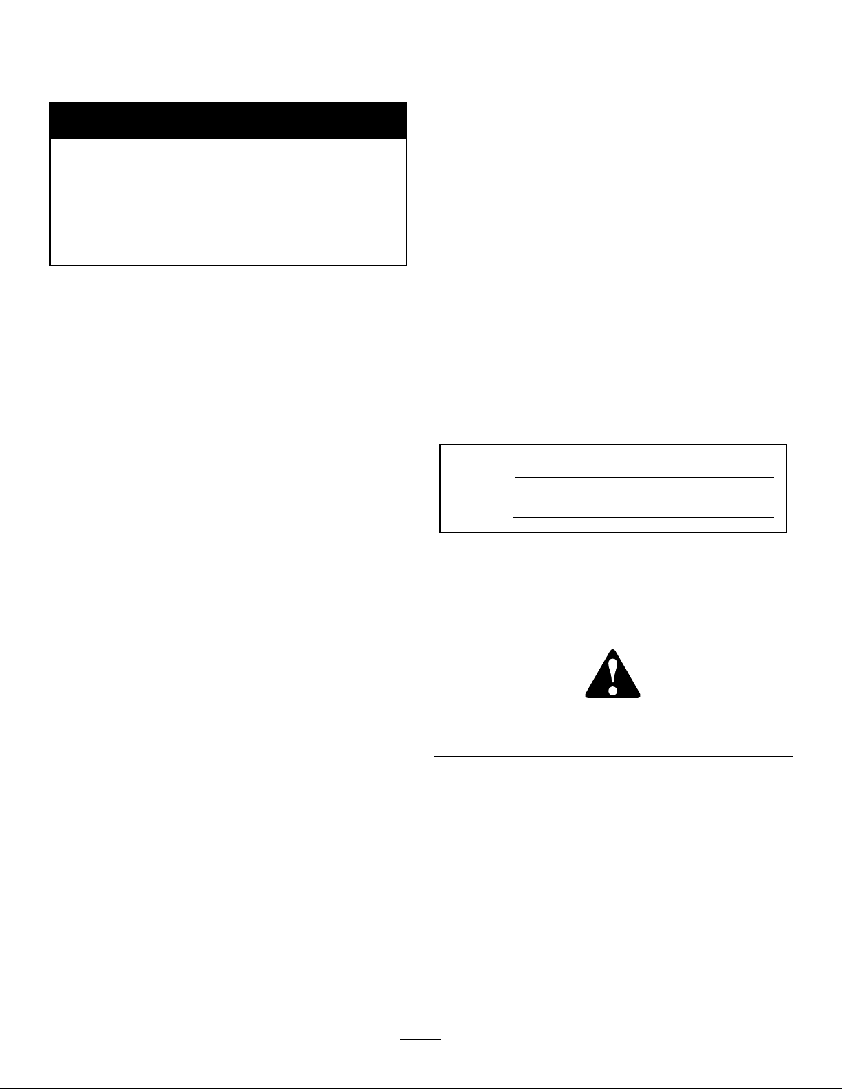
SafetyandInstructionalDecals
Safetydecalsandinstructionsareeasilyvisibletotheoperatorandarelocatednearanyareaof
potentialdanger.Replaceanydecalthatisdamagedorlost.
119-2482
1.Warning—readtheOperator’sManual.
2.Warning—readtheOperator’sManual,donotoperatethismachineunlessyouaretrained.
3.Crushinghazard,bystanders—keepbystandersasafedistancefromthemachine.
4.Entanglementhazard,armandbody;hotsurfacehazard—donotoperatewithoutcentershroudinplace.
5.Tippinghazard—slowmachinebeforeturning,donotturnathighspeeds.
6.Warning—donotparkthemachineonaslope;beforeleavingthemachine,putthetractioncontrolpedalinneutral,lowerthe
implement,turntheengineoff,andremovetheignitionkey.
7.Warning—readtheOperator’sManual;donottowthemachine.
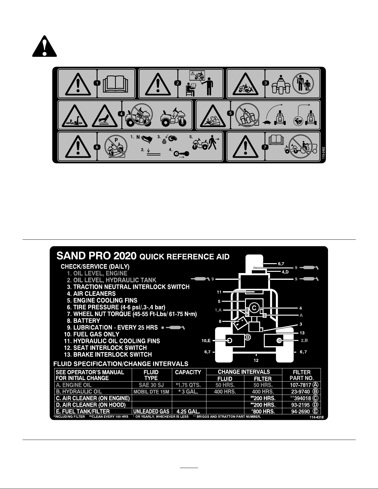
114-4318
7
Page 8
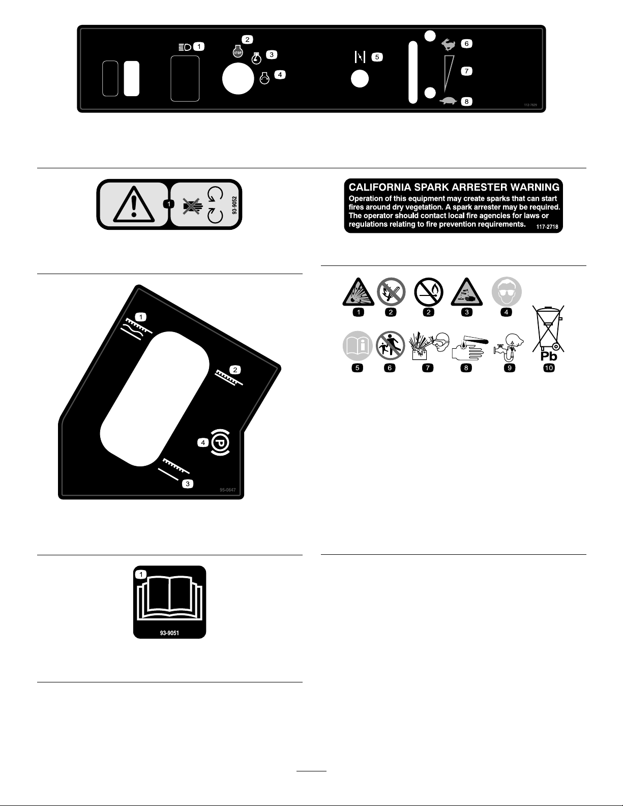
112-7629
1.Headlights3.Engine—run
2.Engine—stop4.Engine—start6.Fast
5.Choke7.Continuousvariablesetting
8.Slow
93-9052
1.Warning—stayawayfrommovingparts.
95-0647
1.Implementoatposition
2.Implementlowerposition4.Parkingbrake
3.Implementraiseposition
117–2718
BatterySymbols
Someorallofthesesymbolsareonyourbattery
1.Explosionhazard
2.Nore,opename,or
smoking.
3.Causticliquid/chemical
burnhazard
4.Weareyeprotection9.Flusheyesimmediately
5.ReadtheOperator’s
Manual.
6.Keepbystandersasafe
7.Weareyeprotection;
8.Batteryacidcancause
10.Containslead;donot
distancefromthebattery .
explosivegasescan
causeblindnessandother
injuries
blindnessorsevereburns.
withwaterandgetmedical
helpfast.
discard.
1.ReadtheOperator’sManual.
93–9051
8
Page 9

Setup
LooseParts
Usethechartbelowtoverifythatallpartshavebeenshipped.
ProcedureDescription
Steeringwheel
1
2
3
4
Rollpin(1/4x2inch)
Bulkelectrolyte,1.260specicgravity
(notincluded)
Bolt(5/8inch)
Locknut(5/8inch)
Refusecontainer
MediaandAdditionalParts
Description
Capscrew(1/2x1–1/4inch)
Washer(1/2inch)
Cylinderpin
Cotterpin
Operator’sManual
EngineOperator’sManual
PartsCatalog
OperatorTrainingMaterials
Key2
CerticateofCompliance
Qty.
Qty.
1
1
-
2
2
1
4
4
1
2
1
1
1
1
1
Readthemanualsandviewthetrainingmaterialsbefore
operatingthemachine.Usetheremainingpartsforthe
installationofattachments.
Installthesteeringwheel.
Activateandchargethebattery.
Installthebattery
Installtherefusecontainer
Use
Use
Note:Determinetheleftandrightsidesofthemachinefromthenormaloperatingposition.
Note:Removeanddiscardalltheshippingbracketsandfasteners.
9
Page 10
1
2
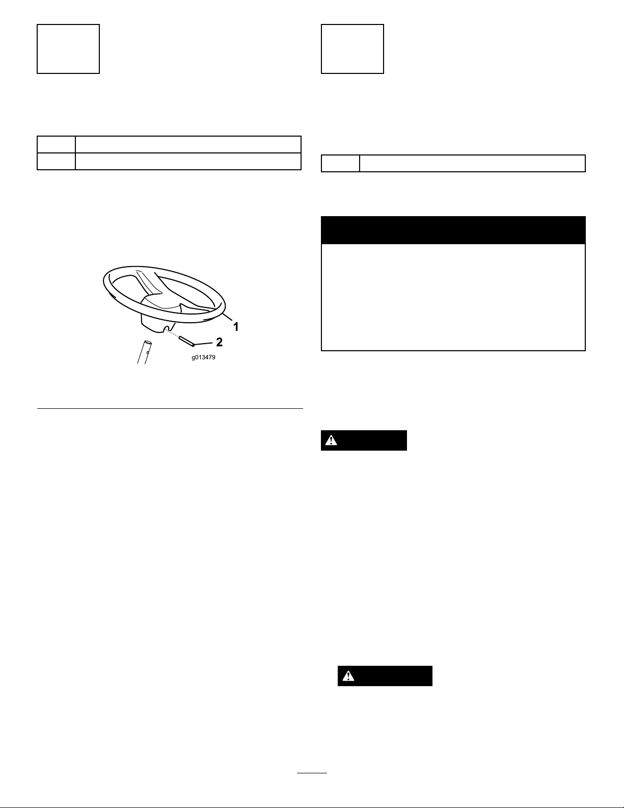
InstallingtheSteeringWheel
Partsneededforthisprocedure:
1
Steeringwheel
1
Rollpin(1/4x2inch)
Procedure
1.Movethefrontwheelsothatitpointsstraightahead.
2.Slidethesteeringwheelontothesteeringshaft
(Figure2).
Figure2
1.Steeringwheel
3.Securethesteeringwheelinplacewiththerollpin
Figure2).
(
2.Rollpin
ActivatingandChargingthe
Battery
Partsneededforthisprocedure:
-
Bulkelectrolyte,1.260specicgravity(notincluded)
Procedure
WARNING
CALIFORNIA
Proposition65Warning
Batteryposts,terminals,andrelated
accessoriescontainleadandleadcompounds,
chemicalsknowntotheStateofCalifornia
tocausecancerandreproductiveharm.
Washhandsafterhandling.
Ifthebatteryisnotlledwithelectrolyteoractivated,
bulkelectrolytewith1.260specicgravitymustbe
purchasedfromalocalbatterysupplyoutletandadded
tothebattery.
DANGER
Batteryelectrolytecontainssulfuricacidwhichisa
deadlypoisonandcausessevereburns.
•Donotdrinkelectrolyteandavoidcontactwith
skin,eyesorclothing .Wearsafetyglassesto
shieldyoureyesandrubberglovestoprotect
yourhands.
•Fillthebatterywherecleanwaterisalways
availableforushingtheskin.
1.Removethellercapsfromthebatteryandslowly
lleachcelluntilelectrolyteisuptothellline.
2.Replacethellercapsandconnecta3to4amp.
batterychargertothebatteryposts.Chargethe
batteryatarateof3to4amperesfor4to8hours.
WARNING
Chargingthebatteryproducesgassesthatcan
explode.
Neversmokenearthebatteryandkeepsparks
andamesawayfrombattery.
10
Page 11
3.Whenthebatteryischarged,disconnectthecharger
fromtheelectricaloutletandbatteryposts.Allow
thebatterytositfor5-10minutes.
4.Removethellercaps.Slowlyaddelectrolyteto
eachcelluntilthelevelisuptothellline.Install
thellercaps.
Important:Donotoverllthebattery.
Electrolytewilloverowontootherpartsofthe
machineandseverecorrosionanddeterioration
willresult.
WARNING
Incorrectbatterycableroutingcoulddamage
themachineandcablescausingsparks.Sparks
cancausethebatterygassestoexplode,
resultinginpersonalinjury.
•Alwaysdisconnectthenegative(black)
batterycablebeforedisconnectingthe
positive(red)cable.
•Alwaysconnectthepositive(red)battery
cablebeforeconnectingthenegative(black)
cable.
3
InstallingtheBattery
Partsneededforthisprocedure:
2
Bolt(5/8inch)
2
Locknut(5/8inch)
Procedure
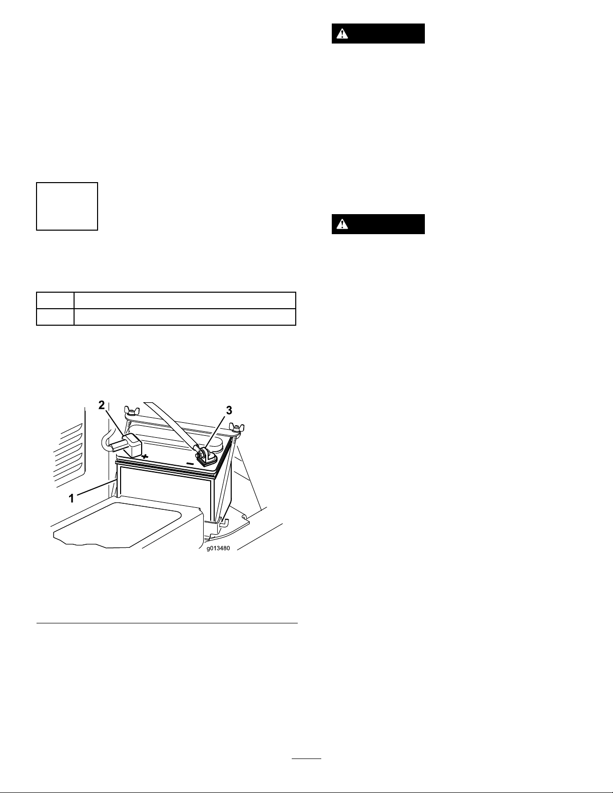
1.Setthebatteryinplace,withthenegativeterminal
positionedtotheoutsideofthemachine(Figure3).
Figure3
1.Battery
2.Positive(+)battery
terminal
3.Negative(-)battery
terminal
WARNING
Batteryterminalsormetaltoolscouldshort
againstmetalmachinecomponentscausing
sparks.Sparkscancausethebatterygassesto
explode,resultinginpersonalinjury.
•Whenremovingorinstallingthebattery,do
notallowthebatteryterminalstotouchany
metalpartsofthemachine.
•Donotallowmetaltoolstoshortbetween
thebatteryterminalsandmetalpartsofthe
machine.
2.Securethepositivecable(red)tothepositive(+)
terminalwitha5/16x5/8inchboltandlocknut
Figure3).
(
3.Securethesmallblackwireandthenegativecable
(black)tothenegative(-)terminalofthebattery
withabolt(5/16x5/8inch)andlocknut(5/16
inch)(Figure3).
4.Coattheterminalsandmountingfastenerswith
petroleumjellytopreventcorrosion.Slidethe
rubberbootoverthepositive(+)terminaltoprevent
apossibleshortfromoccurring.
5.Installthebatteryclampandsecurethebatterywith
therodsandwingnuts.
11
Page 12

4
InstallingtheRefuseContainer
Partsneededforthisprocedure:
1
Refusecontainer
Procedure
Slidetherefusecontainerontothemountingstudson
thefrontofthefueltank(Figure4).
1.Refusecontainer
Figure4
12
Page 13

ProductOverview
Controls
TractionandStoppingPedal
Thetractionpedal(Figure5)has3functions:tomake
themachinemoveforward,tomoveitbackward,andto
stopthemachine.Usingtheheelandtoeoftheright
foot,depressthetopofthepedaltomoveforwardand
thebottomofpedaltomovebackwardortoassistin
stoppingwhenmovingforward(
thepedaltomoveormoveittotheneutralpositionto
stopthemachine.Foroperatorcomfort,donottherest
heelofthefootonreversewhenoperatingforward.
Figure6).Also,allow
CAUTION
Usethemaximumgroundspeedonlywhendriving
fromoneareatoanother.
Maximumspeedisnotrecommendedwhenusing
amountedortowedattachment.
Important:Donotoperateinreversewiththe
attachmentinthedown(operating)positionorthe
attachmentcouldbeseverelydamaged.
IgnitionSwitch
Theignitionswitch(Figure7),usedtostartandstopthe
engine,hasthreepositions:Off,Run,andStart.Rotate
thekeyclockwisetotheStartpositiontoengagethe
startermotor.Releasethekeywhentheenginestarts.
ThekeywillmoveautomaticallytotheOnposition.To
shuttheengineoff,rotatethekeycounterclockwiseto
theOffposition.
Figure5
1.Tractionandstoppingpedal
Figure6
Groundspeedisproportionatetohowthefartraction
pedalisdepressed.Formaximumgroundspeed,the
pedalmustbefullydepressedwhilethethrottleisin
theFastposition.Togetmaximumpowerorwhen
ascendingahill,havethethrottleintheFastposition
whiledepressingthepedalslightlytokeeptheengine
RPMhigh.WhentheengineRPMbeginstodecrease,
releasethepedalslightlytoallowtheRPMtoincrease.
Important:Formaximumpullingpower,the
throttleshouldbeintheFastpositionandthe
tractionpedaljustbarelydepressed.
Figure7
1.Ignitionkey
2.Chokecontrol6.Lights(optional)
3.Throttlecontrol
4.Hourmeter
5.Fuse(optionlights)
7.Fuse(main)
ChokeControl
Tostartacoldengine,closethecarburetorchokeby
pullingthechokecontrol(Figure7)outtotheOn
position.Aftertheenginestarts,regulatethechoketo
keeptheenginerunningsmoothly.Assoonaspossible,
openthechokebypushingitdownwardtotheOff
position.Awarmenginerequireslittleornochoking.
ThrottleControl
Thethrottlecontrollever(Figure7)connectstoand
operatesthethrottlelinkagetothecarburetor.The
13
Page 14

controlhas2positions:SlowandFast.Theengine
g016653
speedcanbevariedbetweenthe2settings.
Note:Theenginecannotbestoppedbythethrottle
control.
HourMeter
Thehourmeter(Figure7),indicatesthetotalhoursof
machineoperation.Thehourmeterstartstofunction
wheneverthekeyswitchisrotatedtotheOnposition.
LiftLever
Toraisetheattachment,pulltheliftlever(Figure8)
back;tolowertheattachment,pushtheleverforward.
Fortheoatposition,movetheleverintothedetent
position.Whenthedesiredpositionisattained,release
theleveranditwillreturntoneutral.
Figure8
1.Liftlever
2.Parkingbrake
Figure9
1.Fuelshutoffvalve
SeatAdjustment
Movetheleveronthesideoftheseatoutward,slide
theseattothedesiredposition,andreleasetheleverto
locktheseatintoposition.
Anadditional2-1/2inches(64mm)offorward
adjustmentmaybeattainedby,proceedasfollows:
1.Removethe(4)locknutssecuringtheseatslidesto
theseatplate.
2.Movetheseat/slidestotheforwardsetofmounting
holesintheseatplate.
3.Securetheseatslidestotheseatplatewiththe
locknutspreviouslyremoved.
Specications
Note:Themachinehasadouble-actingliftcylinder.
Downpressurecanbeappliedtotheattachmentfor
certainoperatingconditions.
ParkingBrake
Toengagetheparkingbrake(Figure8)pullbackon
theparkingbrakelever.T odisengageit,pushthelever
forward.
FuelShutoffValve
Closethefuelshutoffvalve(Figure9)whenstoringor
traileringthemachine.
Note:Specicationsanddesignaresubjecttochange
withoutnotice.
Widthwithoutattachment
Widthwithrake,modelnumber
08812
Lengthwithoutrake
Height
Wheelbase
Netweight
57–1/2inches(146cm)
75inches(191cm)
76inches(163cm)
45inches(114cm)
42-3/4inches(109cm)
834lb.(378kg)
Attachments/Accessories
AselectionofToroapprovedattachmentsand
accessoriesareavailableforusewiththemachineto
enhanceandexpanditscapabilities.Contactyour
AuthorizedServiceDealerorDistributororgoto
www.Toro.comforalistofallapprovedattachments
andaccessories.
14
Page 15

Operation
Note:Determinetheleftandrightsidesofthe
machinefromthenormaloperatingposition.
4.Installthedipstickrmlyinplace.
Important:Thedipstickmustbefullyseated
inthetubetoprovidepropersealingofthe
enginecrankcase.Failuretosealthecrankcase
mayresultinenginedamage.
CheckingtheEngineOilLevel
ServiceInterval:Beforeeachuseordaily
Theengineisshippedwithoilinthecrankcase;
however,theoillevelmustbecheckedbeforeandafter
theengineisrststarted.
Crankcasecapacityisapproximately1-3/4USquarts
(1.66l)withthelter.
Usehigh-qualityengineoilthatmeetsthefollowing
specications:
•APIClassicationLevelRequired:SJ,SK,SLor
higher.
•Preferredoil:SAE30(above40degreesF)
1.Positionthemachineonalevelsurface.
2.Pivotseatrearward.
3.Pulloutthedipstick(
cleanrag.Insertthedipstickintothetubeandmake
surethatitisseatedfully .Removethedipstickfrom
thetubeandchecktheoillevel.Iftheoillevelis
low,removethellercapfromthevalvecoverand
addenoughoiltoraisetheleveltotheFullmark
onthedipstick.
Important:Besuretokeeptheengineoillevel
betweentheupperandlowerlimitsontheoil
gauge.Enginefailuremayoccurasaresultof
overllingorunderllingtheengineoil.
Figure10)andwipeitwitha
5.Pivottheseatdown.
Important:Checktheoillevelevery8
operatinghoursordaily.Initially,changethe
oilaftertherst8hoursofoperation;thereafter,
undernormalconditions,changetheoiland
lterevery50hours.However,changetheoil
morefrequentlywhentheengineisoperatedin
extremelydustyordirtyconditions.
FillingtheFuelTank
UseUnleadedregulargasolinesuitableforautomotive
use(87pumpoctaneminimum).Leadedregular
gasolinemaybeusedifunleadedregularisnotavailable.
Fueltankcapacityisapproximately4-1/2gallons
(16.1l).
DANGER
Incertainconditions,gasolineisextremely
ammableandhighlyexplosive.Areorexplosion
fromgasolinecanburnyouandothersandcan
damageproperty.
•Fillthefueltankoutdoors,inanopenarea,
whentheengineiscold.Wipeupanygasoline
thatspills.
•Neverllthefueltankinsideanenclosedtrailer.
•Donotllthefueltankcompletelyfull.Add
gasolinetothefueltankuntilthelevelis1inch
(25mm)belowthebottomofthellerneck.
Thisemptyspaceinthetankallowsgasoline
toexpand.
•Neversmokewhenhandlinggasoline,andstay
awayfromanopenameorwheregasoline
fumesmaybeignitedbyaspark.
•Storegasolineinanapprovedcontainerand
keepitoutofthereachofchildren.Neverbuy
morethana30-daysupplyofgasoline.
•Donotoperatewithoutentireexhaustsystem
inplaceandinproperworkingcondition.
Figure10
1.Dipstick
2.Oilllcap
15
Page 16

DANGER
Incertainconditionsduringfueling,static
electricitycanbereleasedcausingasparkwhich
canignitethegasolinevapors.Areorexplosion
fromgasolinecanburnyouandothersandcan
damageproperty.
•Alwaysplacegasolinecontainersontheground
awayfromyourvehiclebeforelling.
•Donotllgasolinecontainersinsideavehicle
oronatruckortrailerbedbecauseinterior
carpetsorplastictruckbedlinersmayinsulate
thecontainerandslowthelossofanystatic
charge.
•Whenpractical,removegas-powered
equipmentfromthetruckortrailerandrefuel
theequipmentwithitswheelsontheground.
Figure11
1.Fueltankcap
4.Wipeupanyfuelthatmayhavespilledtopreventa
rehazard.
•Ifthisisnotpossible,thenrefuelsuch
equipmentonatruckortrailerfromaportable
container,ratherthanfromagasolinedispenser
nozzle.
•Ifagasolinedispensernozzlemustbeused,
keepthenozzleincontactwiththerimofthe
fueltankorcontaineropeningatalltimesuntil
fuelingiscomplete.
WARNING
Gasolineisharmfulorfatalifswallowed.
Long-termexposuretovaporscancauseserious
injuryandillness.
•Avoidprolongedbreathingofvapors.
•Keepfaceawayfromnozzleandgastankor
conditioneropening .
•Keepgasawayfromeyesandskin.
1.Cleantheareaaroundthefueltankcap(Figure11).
2.Removethefueltankcap.
3.Fillthetanktoabout1in.(25mm)belowthetop
ofthetank(bottomofthellerneck).Donot
overll.Installthecap.
Important:Neverusemethanol,gasoline
containingmethanol,orgasoholcontaining
morethan10%ethanolbecausethefuelsystem
couldbedamaged.Donotmixoilwith
gasoline.
CheckingtheHydraulicFluid
Level
ServiceInterval:Beforeeachuseordaily
Thereservoirislledatthefactorywithapproximately
3U.S.gallons(11.4l)ofhighqualityhydraulicuid.
Checkthelevelofthehydraulicuidbeforethe
engineisrststartedanddailythereafter.The
recommendedreplacementuidisasfollows:
ToroPremiumAllSeasonHydraulicFluid(Availablein5
gallonpailsor55gallondrums.SeepartscatalogorT oro
distributorforpartnumbers.)
Alternateuids:IftheT orouidisnotavailable,other
uidsmaybeusedprovidedtheymeetallthefollowing
materialpropertiesandindustryspecications.W edo
notrecommendtheuseofsyntheticuid.Consult
withyourlubricantdistributortoidentifyasatisfactory
product
Note:Torowillnotassumeresponsibilityfordamage
causedbyimpropersubstitutions,souseonlyproducts
fromreputablemanufacturerswhowillstandbehind
theirrecommendation.
16
Page 17

HighViscosityIndex/LowPourPointAntiwear
HydraulicFluid,ISOVG46
MaterialProperties:
Viscosity,ASTMD445cSt@40°C44to48
ViscosityIndexASTM
D2270
PourPoint,ASTMD97-34°Fto-49°F
IndustrySpecications:
VickersI-286-S(QualityLevel),VickersM-2950-S
(QualityLevel),DenisonHF-0
cSt@100°C9.1to9.8
140to160
Note:Manyhydraulicuidsarealmostcolorless,
makingitdifculttospotleaks.Areddyeadditivefor
thehydraulicsystemoilisavailablein2/3oz.(20ml)
bottles.Onebottleissufcientfor4-6gal(15-221)of
hydraulicoil.Orderpartnumber44-2500fromyour
authorizedTorodistributor.
BiodegradableHydraulicFluid-Mobil224H
ToroBiodegradableHydraulicFluid
(Availablein5gallonpailsor55gallondrums.Seeparts
catalogorTorodistributorforpartnumbers.)
Alternateuid:MobilEAL224H
Thisisvegetable-oilbasedbiodegradableoiltestedand
approvedbyToroforthismodel.Thisuidisnotas
resistanttohightemperaturesasstandarduid,somake
suretofollowrecommendeduidchangeintervalswith
thisuid.Contaminationbymineral-basedhydraulic
uidswillchangethebiodegradabilityandtoxicityof
thisoil.Whenchangingfromstandarduidtothe
biodegradabletype,becertaintofollowtheapproved
ushingprocedure.ContactyourlocalToroDistributor
fordetails.
4.Iftheuidlevelislow ,slowlyllthereservoir
withtheappropriatehydraulicuiduntilthelevel
reachestheneckeddownareaonthedipstick.Do
notoverll.
5.Installthereservoircap.
Important:Topreventsystemcontamination,
cleanthetopofthehydraulicoilcontainers
beforepuncturing .Ensurethatthepourspout
andfunnelareclean.
CheckingtheTirePressure
ServiceInterval:Beforeeachuseordaily
Checkthetirepressurebeforeoperatingthemachine
(Figure13).Thecorrectairpressureinthefrontand
reartiresare:
•forTreadedtires4-6psi(0.3-0.4bar)
•forSmoothtires8-10psi(0.5-0.7bar)
1.Cleantheareaaroundthehydraulicoilreservoircap
topreventdebrisfromenteringtank(
Figure12
1.Oilreservoircap
Figure12).
2.Removethecapfromthereservoir.
3.Checktheoillevelinthereservoir.Theoillevel
shouldbeuptothetopoftheconepointonthe
tankscreen.
Figure13
1.Valvestem2.Lugnut
TorquetheWheelLugNuts
ServiceInterval:Aftertherst8hours
Every100hours
Initially,torquethewheellugsaftertherst8hoursof
operation;thereafter,torquethenutsafterevery100
operatinghours.Torquethelugsnutsto45-55ft-lb
(61-75N⋅m).
StartingandStoppingthe
Engine
1.Removeyourfootfromthetractionpedal,make
surethatthepedalisintheneutralposition,and
engagetheparkingbrake.
17
Page 18

2.PullthechokeleverouttotheOnposition(when
startingacoldengine)andthethrottlelevertothe
Slowposition.
Important:Whenoperatingthemachinein
temperatureslessthan32°F(0°C)allowthe
machinetimetowarmupbeforeusing .This
preventsdamagetothehydrostatandthe
tractionloop.
3.Insertthekeyintotheignitionswitchandrotateit
clockwisetostarttheengine.Releasethekeywhen
theenginestarts.Regulatethechoketokeepthe
enginerunningsmoothly.
Important:Topreventoverheatingofthe
startermotor,donotengagethestarterlonger
than10seconds.After10secondsofcontinuous
cranking,wait60secondsbeforeengagingthe
startermotoragain.
Important:Whentheengineisstartedforthe
rsttime,orafteranoverhauloftheengine,
operatethemachineinforwardandreversefor
1to2minutes.Alsooperatetheliftlevertobe
sureofproperoperationofallparts.
2.Sitontheseatandengagetheparkingbrake.
3.Depressthetractionpedalinforwardandreverse
whiletryingtostarttheengine.
4.Iftheenginecranks,theremaybeamalfunctionin
theinterlocksystem.Repairitimmediately.
5.Iftheenginedoesnotcrank,thesystemisoperating
correctly.
6.Withtheoperatorintheseat,tractionpedalin
neutralandparkingbrakeon,theengineshould
start.Liftofftheseatandslowlydepressthe
tractionpedal,theengineshouldstopinoneto
threeseconds.Correctproblemifnotoperating
properly.
7.Withtheoperatorontheseat,theparkingbrake
engagedandtheenginerunning,Depressthe
tractionpedalinforwardandreverse.Theengine
shouldstopwithin2seconds.Iftheenginedoesnot
stop,theremaybeamalfunctionintheinterlock
system.Repairitimmediately.Iftheenginedoes
stop,thesystemisoperatingcorrectly.
TowingtheMachine
4.Tostoptheengine,movethethrottlecontroltothe
SlowpositionandrotatetheignitionkeytoOff.
Engagetheparkingbrakeandremovethekeyfrom
theswitchtopreventaccidentalstarting.
5.Closethefuelshutoffvalvebeforestoringthe
machine.
CAUTION
Shuttheengineoffandwaitforallmoving
partstostopbeforecheckingforoilleaks,loose
parts,andothermalfunctions.
CheckingtheInterlockSystem
CAUTION
Ifsafetyinterlockswitchesaredisconnectedor
damagedthemachinecouldoperateunexpectedly
causingpersonalinjury.
•Donottamperwiththeinterlockswitches.
•Checktheoperationoftheinterlockswitches
dailyandreplaceanydamagedswitchesbefore
operatingthemachine.
Thepurposeoftheinterlocksystemistopreventthe
enginefromcrankingorstartingunlessthetraction
pedalisintheneutralposition.
Incaseofemergency,themachinecanbetowedfora
shortdistance.However,wedonotrecommendthis
asastandardprocedure.
Important:Donottowthemachinefasterthan
2–3MPH(3–5km/h)becausethedrivesystem
maybedamaged.Ifthemachinemustbemoved
aconsiderabledistance,transportitonatruck
ortrailer.Thetiresmaylockupifthemachine
istowedtoofast.Ifthisoccurs,stoptowingthe
machineandwaitforthetractioncircuitpressure
tostabilizebeforeresumingtowingataslower
speed.
Break-inPeriod
Only8hoursofoperatingtimeisrequiredforthe
break-inperiod.
Sincethersthoursofoperationarecriticaltofuture
dependabilityofthemachine,monitoritsfunctions
andperformancecloselysothatminordifculties,
whichcouldleadtomajorproblems,arenotedandcan
becorrected.Inspectthemachinefrequentlyduring
break-inforsignsofoilleakage,loosefasteners,orany
othermalfunction.
OperatingCharacteristics
1.Checktheinterlockoperationinawideopenarea
freeofdebrisandbystanders.Stoptheengine.
Refertotheattachmentoperator’ smanualforspecic
operatinginstructionsfortheattachment.
18
Page 19

Practicedrivingthemachinebecauseitsoperating
characteristicsaredifferentthansomeutilityvehicles.
Twopointstoconsiderwhenoperatingthevehicleare
transmissionandenginespeed.
TomaintainsomewhatconstantengineRPM,depress
thetractionpedalslowly.Thisallowstheenginetokeep
upwiththegroundspeedofthevehicle.Bycontrast,
pushingdownquicklyonthetractionpedalwillreduce
engineRPMand,asaresult,therewillnotbeenough
torque-powertomovethevehicle.Therefore,to
transfermaximumpowertotherearwheels,move
thethrottletoFastandslightlydepressthetraction
pedal.Bycomparison,maximumgroundspeedwithno
loadresultswhenthethrottleisintheFastposition
andthetractionpedalisslowlybutfullydepressed.In
summary,alwayskeeptheengineRPMhighenoughto
delivermaximumtorque-powertotherearwheels.
CAUTION
Operatingthemachinedemandsattentionto
preventtippingorlossofcontrol.
•Usecarewhenenteringandleavingsandtraps.
•Useextremecautionaroundditches,creeks,
orotherhazards.
•Usecautionwhenoperatingthemachineon
asteepslope.
•Reduceyourspeedwhenmakingsharpturns
orwhenturningonhillsides.
•Avoidsuddenstopsandstarts.
•Donotgofromreversetofullforwardwithout
rstcomingtoacompletestop.
19
Page 20

Maintenance
Note:Determinetheleftandrightsidesofthemachinefromthenormaloperatingposition.
CAUTION
Ifyouleavethekeyintheignitionswitch,someonecouldaccidentlystarttheengineandseriouslyinjure
youorotherbystanders.
Removethekeyfromtheignitionbeforeyoudoanymaintenance.
RecommendedMaintenanceSchedule(s)
MaintenanceService
Interval
Aftertherst8hours
Beforeeachuseordaily
Every25hours
Every50hours
Every100hours
Every200hours
Every400hours
Every800hours
MaintenanceProcedure
•T orquethewheellugnuts.
•Changetheengineoilandlter.
•Changethehydrauliclter.
•Checktheengineoillevel.
•Checkthehydraulicuidlevel.
•Checkthetirepressure.
•Checktheconditionofthehydrauliclinesandhoses.
•Inspectandcleanthemachine.
•Checkthesafetyinterlockoperation
•Greasethefrontwheelbearings
•Checkthebatteryuidlevelandthecableconnections.
•Changetheengineoilandlter.
•T orquethewheellugnuts.
•Greasethesteeringshaftandsprocket
•Replacetheairlter.
•Changethehydraulicsystemoilandlter.
•Replacethesparkplugs.
•Replacethefuellter.
•Decarbonthecombustionchamber.
•Adjustthevalvesandtorquehead.
•ChecktheengineRPM(atidleandfullthrottle).
•Drainandcleanthefueltank.
Every1,500hours
Important:Refertoyour
•Replacemovinghoses.
•Replacetheneutralandseatinterlockswitches.
Engine Operator’ s Man ual
foradditionalmaintenanceprocedures.
20
Page 21

DailyMaintenanceChecklist
Duplicatethispageforroutineuse.
Fortheweekof: MaintenanceCheckItem
Mon.Tues.Wed.Thurs.Fri.
Checkthesafetyinterlock
operation.
Checkthesteeringoperation.
Checkfuellevel.
Checktheengineoillevel.
Checktheairltercondition.
Cleantheenginecoolingns.
Checkunusualengine
noises.
Checkunusualoperating
noises.
Checkthehydraulicoillevel.
Checkhydraulichosesfor
damage.
Checkforuidleaks.
Checkthetirepressure.
Checktheinstrument
operation.
Touch-updamagedpaint.
Sat.Sun.
NotationforAreasofConcern
Inspectionperformedby:
ItemDate
Premaintenance
Procedures
Important:Thefastenersonthecoversofthis
machinearedesignedtoremainonthecoverafter
removal.Loosenallofthefastenersoneachcovera
fewturnssothatthecoverisloosebutstillattached,
thengobackandloosenthemuntilthecover
Information
comesfree.Thiswillpreventyoufromaccidentally
strippingtheboltsfreeoftheretainers
21
Page 22

Lubrication
GreasingtheMachine
Themachinehasgreasettingsthatmustbelubricated
regularlywithNo.2GeneralPurposeLithiumBase
Grease.Lubricatethefrontwheelbearingsafterevery
25hoursofoperation.Lubricatethesteeringshaftevery
100hours.
Lubricatethefollowingbearingsandbushings:
•Frontwheelbearing(2)(
Figure14)
Figure14
ServiceInterval:Every25hours
Every100hours
1.Wipethegreasettingcleansothatforeignmatter
cannotbeforcedintothebearingorbushing.
2.Pumpgreaseintothebearingorbushing.
3.Wipeupexcessgrease.
•Steeringshaftandsprocket(Figure15)
Figure15
Note:Donotlubricatethesteeringchainunlessit
becomesstiffbecauseofrust.Ifthechainrusts,it
maybelubricatedlightlywithadry-typelubricant.
22
Page 23

EngineMaintenance
necessaryonlyincreasesthechanceofdirtentering
theenginewhenthelterisremoved.
ChangingtheEngineOiland
Filter
ServiceInterval:Aftertherst8hours
Every50hours
Changetheoilandlterinitiallyaftertherst8hoursof
operation;thereafterchangetheoilandthelterevery
50hours.
1.Parkthemachineonalevelsurfaceandturnthe
engineoff.
2.Removethedrainplug(
intoadrainpan.Whentheoilstops,installthedrain
plug.
Figure16)andletoilow
•Besurethecoverisseatedcorrectlyandsealswith
theaircleanerbody .
ReplacingtheAirFilter
ServiceInterval:Every200hours
1.Releasethelatchessecuringtheaircleanercoverto
theaircleanerbody(
1.Aircleanerlatch
2.Dustcap4.Dirtejectionport
Figure17).
Figure17
3.Airlter
Figure16
3.Removetheoillter(Figure16).Applyalightcoat
ofcleanoiltothenewltergasket.
4.Screwthelteronbyhanduntilthegasketcontacts
thelteradapter;thentighten1/2to3/4turn
further.Donotovertighten.
5.Addoiltothecrankcase;refertoCheckingthe
CrankcaseOil.
6.Disposeofusedoilproperly .
ServicingtheRemoteAir
Cleaner
•Checktheaircleanerbodyfordamagewhichcould
causeanairleak.Replaceifdamaged.Checkthe
wholeintakesystemforleaks,damageorloosehose
clamps.
2.Removethecoverfromtheaircleanerbody .Before
removingthelter,uselowpressureair(40psi,
cleananddry)tohelpremovelargeaccumulations
ofdebrispackedbetweenoutsideofprimarylter
andthecanister.
Important:Avoidusinghighpressureairwhich
couldforcedirtthroughthelterintotheintake
tract.Thiscleaningprocesspreventsdebris
frommigratingintotheintakewhentheprimary
lterisremoved.
3.Removeandreplacethelter.
Inspectthenewlterforshippingdamage,checking
thesealingendofthelterandthebody.Donotuse
adamagedelement.Insertthenewlterbyapplying
pressuretotheouterrimoftheelementtoseatitin
thecanister.Donotapplypressuretotheexible
centerofthelter.
Note:Cleaningoftheusedelementisnot
recommendedduetothepossibilityofdamageto
theltermedia.
•Servicetheaircleanerlterevery200hoursorearlier
ifengineperformancesuffersduetoextremelydusty,
dirtyconditions.Changingtheairlterbeforeitis
4.Cleanthedirtejectionportlocatedintheremovable
cover.Removetherubberoutletvalvefromthe
cover,cleanthecavityandreplacetheoutletvalve.
23
Page 24

5.Installthecoverorientingtherubberoutletvalvein
adownwardposition-betweenapproximately5:00
to7:00whenviewedfromtheend.
CleaningtheCylinderHead
Fins
6.Securethelatches.
ReplacingtheSparkPlugs
ServiceInterval:Every800hours
Replacethesparkplugsafterevery800operatinghours
oryearly,whicheveroccursrst.
Type:ChampionRC12YC(orequivalent)
AirGap:0.030in.(0.76mm)
Note:Thesparkplugusuallylastsalongtime;however,
theplugshouldberemovedandcheckedwheneverthe
enginemalfunctions.
1.Cleantheareaaroundthesparkplugssothatforeign
mattercannotfallintothecylinderwhenthespark
plugisremoved.
2.Pullthesparkplugwiresoffofthesparkplugsand
removetheplugsfromthecylinderhead.
3.Checktheconditionofthesideelectrode,center
electrode,andcenterelectrodeinsulatortoensure
thatthereisnodamage.
Toavoidoverheatingandpossibleenginedamage,the
coolingnsonthecylinderheadmustbekeptclean.
Important:Acracked,fouled,dirty,or
otherwisemalfunctioningsparkplugmustbe
replaced.Donotsand-blast,scrape,orclean
theelectrodesbyusingawirebrushbecause
gritmayeventuallyreleasefromtheplugand
fallintothecylinder.Theresultisusuallya
damagedengine.
4.Settheairgapbetweenthecenterandsideofthe
electrodesat0.030in.(0.76mm)(
thecorrectlygappedsparkplugwithgasketseal,and
tightentheplugto200in-lb(23N⋅m).Ifatorque
wrenchisnotused,tightentheplugrmly.
Figure18).Install
Figure18
24
Page 25

FuelSystem
G008963
12
3
ElectricalSystem
Maintenance
ReplacingtheFuelFilter
ServiceInterval:Every800hours
Aninlinelterisincorporatedintothefuelline.Change
thelterevery800hours.Usethefollowingprocedures
whenreplacementbecomesnecessary:
1.Closefuelshutoffvalve,loosenthehoseclampon
thecarburetorsideoflterandremovethefuelline
fromthelter(
Figure19).
Maintenance
WARNING
CALIFORNIA
Proposition65Warning
Batteryposts,terminals,andrelated
accessoriescontainleadandleadcompounds,
chemicalsknowntotheStateofCalifornia
tocausecancerandreproductiveharm.
Washhandsafterhandling.
CaringfortheBattery
ServiceInterval:Every25hours
Thebatteryelectrolytelevelmustbeproperlymaintained
andthetopofthebatterykeptclean.Ifthemachineis
storedinalocationwheretemperaturesareextremely
high,thebatterywillrundownmorerapidlythanif
themachineisstoredinalocationwheretemperatures
arecool.
Figure19
1.Fuellter
2.Hoseclamps
2.Placeadrainpanunderlter,loosentheremaining
hoseclampandremovelter.
3.Installthenewlterwitharrowonthelterbody
pointingawayfromthefueltank(towardcarburetor).
4.Slidethehoseclampsontotheendsofthefuellines.
Pushthefuellinesontothefuellterandsecure
themwiththehoseclamps.Besurethatthearrow
onthesideofthelterpointstowardthecarburetor.
3.Fuelline
DANGER
Batteryelectrolytecontainssulfuricacidwhichisa
deadlypoisonandcausessevereburns.
•Donotdrinkelectrolyteandavoidcontactwith
skin,eyesorclothing .Wearsafetyglassesto
shieldyoureyesandrubberglovestoprotect
yourhands.
•Fillthebatterywherecleanwaterisalways
availableforushingtheskin.
Keepthetopofthebatterycleanbywashingit
periodicallywithabrushdippedinammoniaor
bicarbonateofsodasolution.Flushthetopsurfacewith
wateraftercleaning.Donotremovethellcapwhile
cleaning.
Thebatterycablesmustbetightontheterminalsto
providegoodelectricalcontact.
25
Page 26

WARNING
Incorrectbatterycableroutingcoulddamagethe
machineandcablescausingsparks.Sparkscan
causethebatterygassestoexplode,resultingin
personalinjury.
•Alwaysdisconnectthenegative(black)battery
cablebeforedisconnectingthepositive(red)
cable.
•Alwaysconnectthepositive(red)batterycable
beforeconnectingthenegative(black)cable.
Ifcorrosionoccursatthebatteryterminals,disconnect
thecables,negative(-)cablerst,andscrapetheclamps
andterminalsseparately.Reconnectthecables,positive
(+)cablerst,andcoattheterminalswithpetroleum
jelly.
•Checktheelectrolytelevelevery25operatinghours
or,ifthemachineisinstorage,every30days.
•Maintainthecelllevelwithdistilledordemineralized
water.Donotllthecellsabovethellline.
DriveSystem
Maintenance
AdjustingtheTractionDrive
forNeutral
Ifthemachinemoveswhenthetractionpedalisinthe
neutralposition,thetractioncammustbeadjusted.
1.Parkthemachineonalevelsurfaceandturnthe
engineoff.
2.Pivottheseatupwardandremovetheengineshield.
3.Raiseonerearwheeloffoftheoorandplace
supportblocksundertheframe.
4.Loosenthelocknutonthetractionadjustmentcam
Figure20).
(
Figure20
1.Tractionadjustmentcam
2.Locknut
3.Screw
4.Gap
WARNING
Theenginemustberunningsothatthenal
adjustmentofthetractionadjustmentcamcan
beperformed.Contactwithmovingpartsorhot
surfacesmaycausepersonalinjury.
Keephands,feet,face,andotherbodyparts
awayfromrotatingparts,themufer,andother
hotsurfaces.
5.Starttheengineandrotatethecamhex(Figure20)
inbothdirectionstodeterminethemidpositionof
theneutralspan.
6.Tightenthelocknutsecuringtheadjustment.
7.Stoptheengine.
26
Page 27

8.Installtheengineshieldandlowertheseat.
9.Removethejackstandsandlowerthemachineto
theshopoor.Testdrivethemachinetomakesure
thatitdoesnotmovewhenthetractionpedalisin
neutral.
AdjustingtheTraction
InterlockSwitch
AdjustingtheSteeringChain
Sincethechainandsprocketaresubjectedtosand
thrownupbythefronttire,inspectthemfrequentlyfor
wear.Ifeitherthechainorsprocketiswornbeyond
acceptablelimits,bothshouldbereplaced.
1.Placethefrontwheelinthestraightaheadposition
2.Adjustthelocknutsuntilthechainissnugonboth
sidesofthesprocket(
Figure22).
1.Adjustthetransmissionforneutral;referto
AdjustingtheTractionDriveforNeutral.
2.Activatethepumplevertoensurethatallpartsare
operatingfreelyandseatedproperly .
3.Adjustthescrewuntiltheairgapis.060inches
±.030(1.524mm±.762)(
4.Checkforproperoperation.
Figure20).
AdjustingthePedalfor
Forward
Thepedalmustbeadjustedforforwardifthejam
nutsonthecontrolrodareloosenedorifthepedalis
removed.
1.Parkthemachineonalevelsurface,turntheengine
off,andengagetheparkingbrake.
2.Makesurethatthepumpisinneutral.
3.Loosenthejamnutsonthecontrolrod(
4.Pressdownontherearofthepedaluntilthepedal
contactsthefootrest.
Figure21).
3.Turnthesteeringwheelfullleftandfullrighttobe
surethatthechaindoesnotbindorhangupineither
direction.Adjustasrequired.
Figure22
1.Adjustingnuts
5.Adjustthejamnutstoallowfullstrokeofthepump,
slightlydeectingthecontrolrodwhenthepedal
isatfullstroke.
Figure21
1.Pedal
2.Jamnuts
3.Controlrod
27
Page 28

BrakeMaintenance
7.Engageanddisengagetheparkingbraketomake
sureitdoesnotinterferewiththeswitch.
AdjustingtheBrakeInterlock
Switch
1.Parkthemachineonalevelsurfaceandturnthe
engineoff.
2.Disengagetheparkingbrake.
3.Removetheknobfromtheliftlever(Figure23).
8.Testforproperoperation
9.Installthevalveshroud.
10.Adjusttheliftleverguide.RefertoAdjustingthe
LiftLever.
AdjustingtheBrakeLinkage
Thebrakeshavebeensetatthefactoryforoptimum
performance,butafteruseandwearanadjustmentmay
berequired.
1.Parkthemachineonalevelsurface,turntheengine
off,andblockthewheels.
2.Loosenthejamnutontheactuatorrod(
Removethecotterpinretainingtheactuatorrod.
Increaseordecreasetheactuatorrodlengthby
rotatingtherod.Installtheactuatorrodusinganew
cotterpinandsecurethejamnut.
Figure25).
Figure23
1.Liftleverknob
2.Valveshroudmounting
screws
4.Removethe(3)mountingscrewsandremovethe
valveshroud(
Figure23).
5.Loosenthe(2)nutssecuringbrakeinterlockswitch
tobrakesensorbracket(
Figure24).
6.Adjustthebrakeswitchuntiltheairgapbetweenthe
switchandtheparkingbrakeleverlinkis.060inches
±.030.(1.524mm±.762)(Figure24).Tightenthe
switchmountingnuts.
Figure25
1.Actuatorrod
2.Adjustmentrod(2)4.Cotterpin(3)
3.Jamnut(3)
3.Ifmodifyingtheactuatorrodlengthdoesnot
improvebrakeperformance,adjustboththeleft
andrightadjustmentrodsequallyusingthesame
proceduredescribedinstep2.
1.Brakeswitchmounting
knob
Figure24
2.Valveshroudmounting
screws
28
Page 29

ControlsSystem
Maintenance
AdjustingtheLiftLever
Iftheimplementfailstooatwhentheliftleverisin
thedetentposition,anadjustmenttotheleverguideis
required.
1.Parkthemachineonalevelsurface,turntheengine
off,andengagetheparkingbrake.
2.Disconnecttheimplementfromtheliftcylinderand
extendthecylinderpartway.
3.Loosenthecapscrewsandlocknutssecuringthe
leverguide(
4.Movetheleverguideuntilthecylindermovesfreely
whentheliftleverisinthedetentposition.
5.Tightenthecapscrewsandlocknutslockingthe
adjustment.
1.Liftlever
Figure26)tothevalveshroud.
Figure26
2.Leverguide
Figure27
1.Throttlecasingclamp
screw
2.Throttlecable
3.Swivel6.Chokecable
3.Movetheremotethrottlecontrolleverforwardto
theFastposition.
4.Pullrmlyonthethrottlecableuntilthebackofthe
swivelcontactsthestop(
5.Tightenthecableclampscrewandchecktheengine
RPMsetting:
•HighIdle:3150±50
•LowIdle:1750±50
4.Stop
5.Chokecasingclampscrew
Figure27).
AdjustingtheChokeControl
1.Pivottheseatupwardandremovetheengineshield.
2.Loosenthecableclampscrewsecuringthecableto
theengine(Figure27).
3.Movetheremotechokecontrolleverforwardtothe
Closedposition.
AdjustingtheEngineControls
AdjustingtheThrottleControl
Properthrottleoperationisdependentuponproper
adjustmentofthethrottlecontrol.Beforeadjustingthe
carburetor,ensurethatthethrottlecontrolisoperating
properly.
1.Pivottheseatupwardandremovetheengineshield.
2.Loosenthecableclampscrewsecuringthecableto
theengine(
Figure27).
4.Pullrmlyonthechokecable(
chokebutteryiscompletelyclosed;thentightenthe
cableclampscrew .
Figure27)untilthe
AdjusttheEngineGovernorSpeed
Control
Important:Beforetheenginegovernorspeed
controlisadjusted,thethrottleandchokecontrols
mustbeadjustedproperly.
29
Page 30

WARNING
Theenginemustberunningduringadjustmentof
theenginegovernorspeedcontrol.Contactwith
movingpartsorhotsurfacesmaycausepersonal
injury.
•Ensuretractionpedalisinneutralandengage
theparkingbrakebeforeperformingthis
procedure.
•Keephands,feet,clothing,andotherbodyparts
awayfromanyrotatingparts,themufer,and
otherhotsurfaces.
Note:Toadjustthelowidle,useallthefollowingsteps.
Ifonlythehighidleistobeadjusted,proceeddirectly
tostep5.
HydraulicSystem
Maintenance
ChangingtheHydraulic
SystemOilandFilter
ServiceInterval:Aftertherst8hours
Every400hours
Thehydraulicsystemltermustbechangedinitially,
aftertherst8hoursofoperation,andthereafterevery
400hoursofoperationoryearly ,whicheveroccurs
rst.UseagenuineTorooillterforreplacement.
Thehydraulicoilmustbechangedevery400hoursof
operationoryearly,whicheveroccursrst.
1.Starttheengineandletitrunathalfthrottlefor
approximatelyveminutestowarmup.
2.MovethethrottlecontroltotheSlowsetting.Adjust
theidlestopscrewcounterclockwiseuntilitno
longercontactsthethrottlelever.
3.Bendthegovernedidlespringanchortang
Figure28)toattainanidlespeedof1750±50RPM.
(
Checkthespeedwithatachometer.
Figure28
ShownwithCarbAdapterRemoved
1.Parkthemachineonalevelsurfaceandturnthe
engineoff.
2.Pivottheseatupward.
3.Disconnectthetubefromthebottomttingofthe
reservoirandlettheoilowintoadrainpan.Install
andtightenthetubewhentheoilstopsdraining.
4.Cleantheareaaroundthehydraulicoillter
(Figure29).Removethelterfromthebottomof
thelterhousingandallowtheoiltoowintoa
drainpan.Useabottom-typelterwrench.Dispose
oftheoillterproperly
1.Governedidlespring
anchortag
4.Adjusttheidlestopscrewuntiltheidlespeedis
increased25to50RPMovertheidlespeedsetin
step3.Finalidlespeedmustbe1750±100RPM.
5.MovethethrottlecontroltotheFastposition.Bend
thehighspeedspringanchortang(Figure28)to
attainahighspeedof3150±50RPM.
2.Highspeedspringanchor
tag
Figure29
1.Hydrauliclter
5.Applyalmofoilontheltergasket.Installthe
lterbyhanduntilthegasketcontactsthemounting
head;thentightenthelteranadditional3/4turn.
6.Fillthereservoirtotheproperlevel;referto
CheckingtheHydraulicSystem.
7.Placeallofthecontrolsintheneutralordisengaged
positionandstarttheengine.Runtheengineatthe
lowestpossibleRPMtopurgethesystemofair.
30
Page 31

8.Runtheengineuntiltheliftcylinderextendsand
retractsandforwardandreversewheelmotionis
achieved.
9.Stoptheengineandchecktheoillevelinthe
reservoir.Addoilifnecessary
10.Checkallconnectionsforleaks.
11.Lowertheseat.
12.Disposeofusedoilproperly .
CheckingtheHydraulicLines
andHoses
ServiceInterval:Beforeeachuseordaily
(Figure30),allowingthepumpshaftfreedomto
rotateduringstart-up.
Checkthehydrauliclinesandhosesdailyforleaks,kinked
lines,loosemountingsupports,wear,loosettings,
weatherdeterioration,andchemicaldeterioration.Make
allnecessaryrepairsbeforeoperating.
WARNING
Hydraulicuidescapingunderpressurecan
penetrateskinandcauseinjury.
•Makesureallhydraulicuidhosesandlinesare
ingoodconditionandallhydraulicconnections
andttingsaretightbeforeapplyingpressureto
thehydraulicsystem.
•Keepyourbodyandhandsawayfrompin
holeleaksornozzlesthatejecthighpressure
hydraulicuid.
•Usecardboardorpapertondhydraulicleaks.
•Safelyrelieveallpressureinthehydraulicsystem
beforeperforminganyworkonthehydraulic
system.
•Seekimmediatemedicalattentionifuidis
injectedintoskin.
ChargingtheHydraulic
System
Wheneverahydrauliccomponentisrepairedor
replaced,thehydraulicoilltershouldbechangedand
thehydraulicsystemcharged.
Makesurethatthehydraulicreservoirandlterarelled
withoilatalltimeswhenchargingthehydraulicsystem.
1.Parkthemachineonalevelsurfaceandturnthe
engineoff.
2.Pivottheseatupwardandremovetheengineshield.
3.Loosenthelocknutonthespringadjustingpinuntil
thebearingmovesfreelyfromthecamonthelever
Figure30
1.Springadjustingpin3.Cam
2.Bearing
4.Raiseonerearwheeloffoftheoorandplace
supportblocksundertheframe.
5.Starttheengineandsetthethrottletoallowthe
enginetorunatapproximately1800RPM.
6.Actuatetheliftvalveleveruntiltheliftcylinder
rodmovesinandoutseveraltimes.Ifthecylinder
roddoesnotmoveafter10-15secondsorthe
pumpemitsabnormalsounds,shuttheengineoff
immediatelyanddeterminethecauseorproblem.
Inspectforthefollowing:
•Looselterorsuctionlines
•Looseorfaultycoupleronthepump
•Blockedsuctionline
•Faultychargereliefvalve
•Faultychargepump
Ifthecylindermovesin10-15seconds,proceedto
step7.
7.Operatethetractionpedalinforwardandreverse.
Thewheelthatisoffoftheoorshouldrotateinthe
properdirection.Ifthewheelrotatesinthewrong
direction,stoptheengine,removethelinesfromthe
rearofthepumpandreversethelocations.Ifthe
wheelrotatesintheproperdirection,stoptheengine
andadjustthespringadjustingpinlocknut.Adjust
thetractionneutralposition;refertoAdjustingthe
TractionDriveforNeutral.
8.Checktheadjustmentofthetractioninterlock
switch;refertoAdjustingtheTractionInterlock
Switch.
9.Installtheengineshieldandlowertheseat.
31
Page 32

Cleaning
Storage
InspectingandCleaningthe
Machine
ServiceInterval:Beforeeachuseordaily
Atthecompletionofoperation,thoroughlywashthe
machinewithagardenhose-withoutanozzle-sothat
excessivewaterpressurewillnotcausecontamination
anddamagetothesealsandbearings.
Makesurethatthecoolingnsandareaaroundthe
enginecoolingairintakearekeptfreeofdebris.After
cleaning,inspectthemachineforpossiblehydraulic
uidleaks,damage,orweartohydraulicandmechanical
components.
TractionUnit
1.Thoroughlycleanthetractionunit,attachmentsand
theengine.
2.Checkthetirepressure.Refertocheckingthetire
pressure.
3.Checkallfastenersforlooseness;tightenas
necessary.
4.Greaseoroilallgreasettingsandpivotpoints.
Wipeoffanyexcesslubricant.
5.Lightlysandandusetouchuppaintonpaintedareas
thatarescratched,chippedorrusted.
6.Servicethebatteryandcablesasfollows:
A.Removethebatteryterminalsfromthebattery
posts.
B.Cleanthebattery,terminalsandpostswithawire
brushandbakingsodasolution.
C.Coatthecableterminalsandbatterypostswith
Grafo112Xskin-overgrease(ToroPartNo.
505-47),orpetroleumjellytopreventcorrosion.
D.Slowlyrechargethebatteryfor24hoursevery60
daystopreventleadsulfationofthebattery.
Note:Thespecicgravityofafullycharged
batteryis1.250.
Note:Storethebatteryinacoolatmosphereto
avoidquickdeteriorationofthechargeinthebattery.
Topreventthebatteryfromfreezing,makesurethat
itisfullycharged.
Engine
1.Changetheengineoilandlter.RefertoChanging
theEngineOilandFilter.
2.Starttheengineandrunitatidlespeedfortwo
minutes.
3.Thoroughlycleanandservicetheaircleaner
assembly.RefertoServicingtheAirCleaner.
4.Sealtheaircleanerinletandtheexhaustoutletwith
weatherproofmaskingtape.
5.Checktheoilllercap,hydraulicreservoircapand
fueltankcaptoensuretheyaresecurelyinplace.
32
Page 33

Schematics
ElectricalSchematic(Rev.A)
33
Page 34

HydraulicSchematic(Rev.C)
34
Page 35

Notes:
35
Page 36

TheToroTotalCoverageGuarantee
ALimitedWarranty
ConditionsandProductsCovered
TheT oro
toanagreementbetweenthem,jointlywarrantyourT oroCommercial
product(“Product”)tobefreefromdefectsinmaterialsorworkmanship
fortwoyearsor1500operationalhours*,whicheveroccursrst.This
warrantyisapplicabletoallproductswiththeexceptionofAerators
(refertoseparatewarrantystatementsfortheseproducts).Wherea
warrantableconditionexists,wewillrepairtheProductatnocosttoyou
includingdiagnostics,labor,parts,andtransportation.Thiswarranty
beginsonthedatetheProductisdeliveredtotheoriginalretailpurchaser.
*Productequippedwithanhourmeter.
®
Companyanditsafliate,T oroWarrantyCompany,pursuant
InstructionsforObtainingWarrantyService
YouareresponsiblefornotifyingtheCommercialProductsDistributoror
AuthorizedCommercialProductsDealerfromwhomyoupurchasedthe
Productassoonasyoubelieveawarrantableconditionexists.Ifyouneed
helplocatingaCommercialProductsDistributororAuthorizedDealer,or
ifyouhavequestionsregardingyourwarrantyrightsorresponsibilities,
youmaycontactusat:
CommercialProductsServiceDepartment
ToroWarrantyCompany
811 1LyndaleAvenueSouth
Bloomington,MN55420-1196
E-mail:commercial.warranty@toro.com
OwnerResponsibilities
AstheProductowner,youareresponsibleforrequiredmaintenance
andadjustmentsstatedinyourOperator’sManual.Failuretoperform
requiredmaintenanceandadjustmentscanbegroundsfordisallowinga
warrantyclaim.
ItemsandConditionsNotCovered
Notallproductfailuresormalfunctionsthatoccurduringthewarranty
periodaredefectsinmaterialsorworkmanship.Thiswarrantydoesnot
coverthefollowing:
•Productfailureswhichresultfromtheuseofnon-T ororeplacement
parts,orfrominstallationanduseofadd-on,ormodiednon-Toro
brandedaccessoriesandproducts.Aseparatewarrantymaybe
providedbythemanufactureroftheseitems.
•Productfailureswhichresultfromfailuretoperformrecommended
maintenanceand/oradjustments.Failuretoproperlymaintainyour
ToroproductpertheRecommendedMaintenancelistedinthe
Operator’sManualcanresultinclaimsforwarrantybeingdenied.
•ProductfailureswhichresultfromoperatingtheProductinan
abusive,negligentorrecklessmanner.
•Partssubjecttoconsumptionthroughuseunlessfoundtobe
defective.Examplesofpartswhichareconsumed,orusedup,during
normalProductoperationinclude,butarenotlimitedto,brakes
padsandlinings,clutchlinings,blades,reels,bedknives,tines,
sparkplugs,castorwheels,tires,lters,belts,andcertainsprayer
componentssuchasdiaphragms,nozzles,andcheckvalves,etc.
•Failurescausedbyoutsideinuence.Itemsconsideredtobeoutside
inuenceinclude,butarenotlimitedto,weather,storagepractices,
contamination,useofunapprovedcoolants,lubricants,additives,
fertilizers,water,orchemicals,etc.
•Normalnoise,vibration,wearandtear,anddeterioration.
•Normal“wearandtear”includes,butisnotlimitedto,damageto
seatsduetowearorabrasion,wornpaintedsurfaces,scratched
decalsorwindows,etc.
Parts
Partsscheduledforreplacementasrequiredmaintenancearewarranted
fortheperiodoftimeuptothescheduledreplacementtimeforthatpart.
Partsreplacedunderthiswarrantyarecoveredforthedurationofthe
originalproductwarrantyandbecomethepropertyofT oro.Torowill
makethenaldecisionwhethertorepairanyexistingpartorassemblyor
replaceit.T oromayuseremanufacturedpartsforwarrantyrepairs.
NoteRegardingDeepCycleBatteryWarranty:
Deepcyclebatterieshaveaspeciedtotalnumberofkilowatt-hoursthey
candeliverduringtheirlifetime.Operating,recharging,andmaintenance
techniquescanextendorreducetotalbatterylife.Asthebatteriesinthis
productareconsumed,theamountofusefulworkbetweencharging
intervalswillslowlydecreaseuntilthebatteryiscompletelywornout.
Replacementofwornoutbatteries,duetonormalconsumption,isthe
responsibilityoftheproductowner.Batteryreplacementmayberequired
duringthenormalproductwarrantyperiodatowner’sexpense.
MaintenanceisatOwner’sExpense
Enginetune-up,lubricationcleaningandpolishing,replacementof
ItemsandConditionsNotCoveredlters,coolant,andcompleting
RecommendedMaintenancearesomeofthenormalservicesT oro
productsrequirethatareattheowner’sexpense.
GeneralConditions
RepairbyanAuthorizedT oroDistributororDealerisyoursoleremedy
underthiswarranty.
NeitherTheToroCompanynorToroWarrantyCompanyisliablefor
indirect,incidentalorconsequentialdamagesinconnectionwiththe
useoftheT oroProductscoveredbythiswarranty,includingany
costorexpenseofprovidingsubstituteequipmentorserviceduring
reasonableperiodsofmalfunctionornon-usependingcompletion
ofrepairsunderthiswarranty.ExceptfortheEmissionswarranty
referencedbelow,ifapplicable,thereisnootherexpresswarranty.
Allimpliedwarrantiesofmerchantabilityandtnessforusearelimitedto
thedurationofthisexpresswarranty.Somestatesdonotallowexclusions
ofincidentalorconsequentialdamages,orlimitationsonhowlongan
impliedwarrantylasts,sotheaboveexclusionsandlimitationsmaynot
applytoyou.
Thiswarrantygivesyouspeciclegalrights,andyoumayalsohaveother
rightswhichvaryfromstatetostate.
Noteregardingenginewarranty:
TheEmissionsControlSystemonyourProductmaybecoveredby
aseparatewarrantymeetingrequirementsestablishedbytheU.S.
EnvironmentalProtectionAgency(EP A)and/ortheCaliforniaAir
ResourcesBoard(CARB).Thehourlimitationssetforthabovedonot
applytotheEmissionsControlSystemWarranty .RefertotheEngine
EmissionControlW arrantyStatementprintedinyourOperator’sManual
orcontainedintheenginemanufacturer’sdocumentationfordetails
CountriesOtherthantheUnitedStatesorCanada
CustomerswhohavepurchasedT oroproductsexportedfromtheUnitedStatesorCanadashouldcontacttheirT oroDistributor(Dealer)toobtain
guaranteepoliciesforyourcountry ,province,orstate.IfforanyreasonyouaredissatisedwithyourDistributor’sserviceorhavedifcultyobtaining
guaranteeinformation,contacttheT oroimporter.Ifallotherremediesfail,youmaycontactusatT oroWarrantyCompany.
374-0253RevA
 Loading...