

FormNo.3396-642RevA
G023363
SandPro
ModelNo.08706—SerialNo.314000001andUp
ModelNo.08706TC—SerialNo.314000001andUp
®
2040ZTractionUnit
Registeratwww.T oro.com.
OriginalInstructions(EN)
*3396-642*A

ThisproductcomplieswithallrelevantEuropeandirectives.
G023440
1
Fordetails,pleaseseetheseparateproductspecic
DeclarationofConformity(DOC)sheet.
WARNING
CALIFORNIA
Proposition65Warning
Thisproductcontainsachemicalorchemicals
knowntotheStateofCaliforniatocausecancer,
birthdefects,orreproductiveharm.
Theengineexhaustfromthisproduct
containschemicalsknowntotheStateof
Californiatocausecancer,birthdefects,
orotherreproductiveharm.
Introduction
Thismachineisaride-onpieceofutilityequipmentintended
tobeusedbyprofessional,hiredoperatorsincommercial
applications.Itisprimarilydesignedforconditioningsand
trapsonwell-maintainedgolfcoursesandcommercial
grounds.
Readthisinformationcarefullytolearnhowtooperateand
maintainyourproductproperlyandtoavoidinjuryand
productdamage.Youareresponsibleforoperatingthe
productproperlyandsafely.
YoumaycontactTorodirectlyatwww .Toro.comforproduct
andaccessoryinformation,helpndingadealer,ortoregister
yourproduct.
ThissparkignitionsystemcomplieswithCanadianICES-002.
Becauseinsomeareastherearelocal,state,orfederal
regulationsrequiringthatasparkarresterbeusedonthe
engineofthismachine,asparkarresterisavailableas
anoption.Ifyourequireasparkarrester,contactyour
AuthorizedToroServiceDealer.
GenuineT orosparkarrestersareapprovedbytheUSDA
ForestryService.
Important:ItisaviolationofCaliforniaPublic
ResourceCodeSection4442touseoroperatetheengine
onanyforest-covered,brush-covered,orgrass-covered
landwithoutasparkarrestermufermaintainedin
workingorder,ortheengineconstricted,equipped,and
maintainedforthepreventionofre.Otherstatesor
federalareasmayhavesimilarlaws.
Theenclosedengineowner'smanualissuppliedfor
informationregardingtheUSEnvironmentalProtection
Agency(EPA)andtheCaliforniaEmissionControl
Regulationofemissionsystems,maintenance,and
warranty.Replacementsmaybeorderedthroughtheengine
manufacturer.
Wheneveryouneedservice,genuineT oroparts,oradditional
information,contactanAuthorizedServiceDealerorToro
CustomerServiceandhavethemodelandserialnumbersof
yourproductready.Figure1identiesthelocationofthe
modelandserialnumbersontheproduct.Writethenumbers
inthespaceprovided.
©2015—TheToro®Company
8111LyndaleAvenueSouth
Bloomington,MN55420
Figure1
1.Modelandserialnumberlocation
ModelNo.
SerialNo.
Thismanualidentiespotentialhazardsandhassafety
messagesidentiedbythesafetyalertsymbol(Figure2),
whichsignalsahazardthatmaycauseseriousinjuryordeath
ifyoudonotfollowtherecommendedprecautions.
Contactusatwww.Toro.com.
2
PrintedintheUSA
AllRightsReserved

Contents
Figure2
1.Safetyalertsymbol
Thismanualuses2wordstohighlightinformation.
Importantcallsattentiontospecialmechanicalinformation
andNoteemphasizesgeneralinformationworthyofspecial
attention.
Safety...........................................................................4
SafeOperatingPractices...........................................4
SoundPowerLevel..................................................7
SoundPressureLevel...............................................7
VibrationLevel......................................................7
SafetyandInstructionalDecals.................................8
Setup...........................................................................13
1RemovingtheShippingBoard................................14
2InstallinganAttachment.......................................14
3InstallingtheFrontW eights...................................14
ProductOverview.........................................................18
Controls...............................................................18
Specications........................................................20
Attachments/Accessories........................................20
Operation....................................................................20
ThinkSafetyFirst...................................................20
InstallingandRemovingtheWeights.........................21
CheckingtheLeveloftheEngineOil.........................21
FillingtheFuelTank...............................................23
CheckingtheLeveloftheHydraulicFluid..................24
CheckingtheTirePressure......................................25
TorquingtheWheelLugNuts..................................25
UsingtheParkingBrake..........................................25
StartingandStoppingtheEngine..............................26
UsingtheSafetyInterlockSystem.............................26
DrivingtheMachine...............................................27
RakingaSandTrap.................................................28
BreakingintheMachine..........................................29
PushingorTowingtheMachine................................29
TransportingtheMachine........................................30
InstallingaWirelessHourMeter...............................31
OperatingTips......................................................32
Maintenance.................................................................33
RecommendedMaintenanceSchedule(s)......................33
DailyMaintenanceChecklist....................................34
PremaintenanceProcedures........................................35
LiftingtheMachine................................................35
Lubrication...............................................................35
GreasingtheMachine.............................................35
EngineMaintenance..................................................36
ServicingtheEngineOilandFilter............................36
ServicingtheAirCleaner.........................................38
ServicingtheSparkPlugs.........................................39
CheckingandAdjustingtheValveClearance...............39
CleaningandLappingtheValve-Seating
Surface..............................................................39
FuelSystemMaintenance...........................................40
ReplacingtheCarbon-CanisterFilter.........................40
ReplacingtheFuelFilter..........................................40
ElectricalSystemMaintenance....................................41
Jump-StartingtheMachine......................................41
ReplacingtheFuses................................................42
ServicingtheBattery...............................................42
DriveSystemMaintenance.........................................45
AdjustingtheTracking............................................45
3

ReplacingtheDriveBeltandtheTensioner
Pulley................................................................45
ControlsSystemMaintenance.....................................46
AdjustingtheControl-HandlePosition......................46
AdjustingtheControl-HandleLinkage......................47
AdjustingtheControl-HandleDampers....................48
AdjustingtheNeutral-LockResistance......................48
AdjustingtheEngineControls.................................49
HydraulicSystemMaintenance....................................51
CheckingtheHydraulicSystem................................51
ChangingtheHydraulicFluidandFilters....................51
CheckingtheHydraulicLinesandHoses....................53
Cleaning...................................................................54
InspectingandCleaningtheMachine........................54
Storage........................................................................54
StoringtheMachine................................................54
Troubleshooting...........................................................56
Safety
Thismachinehasbeendesignedinaccordance
withANSIB71.4-2012.However,whenyouinstall
attachmentsonthemachine,youmustaddadditional
weighttothemachine,asspecied,tocomplytothe
standards.
Improperlyusingormaintainingthemachinecanresult
ininjury.Toreducethepotentialforinjury,complywith
thesesafetyinstructionsandalwayspayattentiontothe
safetyalertsymbol
Danger—personalsafetyinstruction.Failuretocomply
withtheinstructionmayresultinpersonalinjuryor
death.
SafeOperatingPractices
Training
•ReadtheOperator'sManualandothertrainingmaterial
carefully.Becomefamiliarwiththecontrols,safetysigns,
andtheproperuseoftheequipment.Iftheoperator(s)or
mechanic(s)cannotreadorunderstandtheinformation,
itistheowner'sresponsibilitytoexplainittothem.
•Neverallowchildrenorpeopleunfamiliarwiththese
instructionstouseorservicethemachine.Local
regulationsmayrestricttheageoftheoperator.
•Neveroperatewhilepeople,especiallychildren,orpets
arenearby .
•Keepinmindthattheoperatororuserisresponsiblefor
accidentsorhazardsoccurringtootherpeopleortheir
property.
•Donotcarrypassengers.
•Alldriversandmechanicsshouldseekandobtain
professionalandpracticalinstruction.Theowneris
responsiblefortrainingtheusers.Suchinstructionshould
emphasize:
–theneedforcareandconcentrationwhenworking
withride-onmachines;
–controlofaride-onmachineslidingonaslopewill
notberegainedbytheapplicationofthebrake.The
mainreasonsforlossofcontrolare:
◊insufcientwheelgrip,especiallyonwetgrass;
◊beingdriventoofast;
◊inadequatebraking;
◊thetypeofmachineisunsuitableforthetask;
◊lackofawarenessoftheeffectofground
conditions,especiallyslopes;
◊incorrectattachmentandcounterweight
installation.
•Theowner/usercanpreventandisresponsiblefor
accidentsorinjuriesoccurringtopeopleaswellasdamage
toproperty.
,whichmeansCaution,Warning,or
4

Preparation
•Whileoperatingthemachine,alwayswearsubstantial,
slip-resistantfootwear,longtrousers,hardhat,safety
glasses,andearprotection.Longhair,looseclothing,or
jewelrymaygettangledinmovingparts.Donotoperate
theequipmentwhenbarefootorwearingopensandals.
•Evaluatetheterraintodeterminewhataccessoriesand
attachmentsareneededtoproperlyandsafelyperform
thejob.Useonlyaccessoriesandattachmentsapproved
bythemanufacturer.
•Ensurethattheoperator'spresencecontrols,safety
switches,andshieldsareattachedandfunctioning
properly.Donotoperateunlesstheyarefunctioning
properly.
Operation
•Donotoperatetheengineinaconnedspacewhere
dangerouscarbonmonoxideandotherexhaustgasses
cancollect.
•Operateonlyindaylightoringoodarticiallight.
•Beforeattemptingtostarttheengine,shiftintoneutral,
andengagetheparkingbrake.
•Donotputyourhandsorfeetnearorunderrotating
parts.
•Usingthemachinedemandsattention.T opreventtipping
orlossofcontrol:
–Watchforholesorotherhiddenhazards.
–Usecautionwhenoperatingthemachineonasteep
slope.Reduceyourspeedwhenmakingsharpturns
orwhenturningonhillsides.
–Avoidsuddenstopsandstarts.Donotgofrom
reversetofullforwardwithoutrstcomingtoa
completestop.
–Beforebackingup,looktotherearandensurethat
nooneisbehindthemachine.
–Watchoutfortrafcwhennearorcrossingroads.
Alwaysyieldtherightofway.
•Usecarewhenpullingloadsorusingheavyequipment.
–Useonlyapprovedhitchpoints.
–Limitloadstothosethatyoucansafelycontrol.
–Donotturnsharply.Usecarewhenreversing.
•Neveroperatethemachinewithdamagedguards,shields,
orwithoutprotectivesafetydevicesinplace.Besureall
interlocksareattached,adjustedproperly ,andfunctioning
properly.
•Donotchangetheenginegovernorsettingsoroverspeed
theengine.Operatingtheengineatexcessivespeedmay
increasethehazardofpersonalinjury.
•Beforeleavingtheoperator'sposition:
–stoponlevelground;
–movethecontrolhandlestotheneutralposition;
–settheparkingbrake;
–stoptheengineandremovethekey.
•Raisetheattachmentwhenyoutransportthemachine.
•Stoptheengineinthefollowingsituations:
–beforefuelling;
–beforechecking,cleaning,orworkingonthemachine;
–afterstrikingaforeignobjectorifanabnormal
vibrationoccurs.Inspectthemachinefordamage
andmakerepairsbeforestartingagainandoperating
theequipment.
•Reducethethrottlesettingduringenginerun-out.
•Raisetheattachmentbeforebackingup.
•Lookbehindanddownbeforebackingup,tobesureof
aclearpath.
•Slowdownandusecautionwhenmakingturnsand
crossingroadsandsidewalks.
•Donotoperatethemachineundertheinuenceof
alcoholordrugs.
•Lightningcancausesevereinjuryordeath.Iflightning
isseenorthunderisheardinthearea,donotoperate
themachine;seekshelter.
•Usecarewhenloadingorunloadingthemachineintoa
trailerortruck.
•Usecarewhenapproachingblindcorners,shrubs,trees,
orotherobjectsthatmayobscurevision.
RolloverProtectionSystem
(ROPS)—UseandMaintenance
•TheROPSisanintegralandeffectivesafetydevice.Keep
afoldingROPSintheraisedandlockedpositionanduse
theseatbeltwhenoperatingthemachine.
•LowerafoldingROPStemporarilyonlywhenabsolutely
necessary.Donotweartheseatbeltwhenfoldeddown.
•Beawarethereisnorolloverprotectionwhenafolded
ROPSisinthedownposition.
•Becertainthattheseatbeltcanbereleasedquicklyin
theeventofanemergency.
•Checktheareatobemowedandneverfolddowna
foldingROPSinareaswherethereareslopes,dropoffs
orwater.
•Checkcarefullyforoverheadclearances(i.e.branches,
doorways,electricalwires)beforedrivingunderany
objectsanddonotcontactthem.
•KeeptheROPSinsafeoperatingconditionby
periodicallythoroughlyinspectingfordamageand
keepingallmountingfastenerstight.
•ReplaceadamagedROPS.Donotrepairorrevise.
•DonotremovetheROPS.
•AnyalterationstoaROPSmustbeapprovedbythe
manufacturer.
5

SafeHandlingofFuels
•Toavoidpersonalinjuryorpropertydamage,use
extremecareinhandlinggasoline.Gasolineisextremely
ammableandthevaporsareexplosive.
•Extinguishallcigarettes,cigars,pipes,andothersources
ofignition.
•Useonlyanapprovedfuelcontainer.
•Neverremovefuelcaporaddfuelwiththeengine
running.
•Allowenginetocoolbeforerefueling.
•Neverrefuelthemachineindoors.
•Neverstorethemachineorfuelcontainerwherethereis
anopename,spark,orpilotlightsuchasonawater
heateroronotherappliances.
•Neverllcontainersinsideavehicleoronatruckor
trailerbedwithaplasticliner.Alwaysplacecontainerson
thegroundawayfromyourvehiclebeforelling.
•Removeequipmentfromthetruckortrailerandrefuelit
ontheground.Ifthisisnotpossible,thenrefuelsuch
equipmentwithaportablecontainer,ratherthanfroma
fueldispensernozzle.
•Keepthenozzleincontactwiththerimofthefueltank
orcontaineropeningatalltimesuntilfuelingiscomplete.
•Donotuseanozzlelockopendevice.
•Iffuelisspilledonclothing,changeclothingimmediately.
•Neveroverllfueltank.Replacefuelcapandtighten
securely.
MaintenanceandStorage
•Keepallnuts,bolts,andscrewstighttobesurethatthe
equipmentisinsafeworkingcondition.
•Neverstorethemachinewithfuelinthetankinsidea
buildingwherefumesmayreachanopenameoraspark.
•Allowtheenginetocoolbeforestoringthemachinein
anyenclosure.
•Toreducetherehazard,keeptheengine,mufer,
batteryarea,andfuel-storageareafreeofgrass,leaves,
andexcessivegrease.
•Keepallpartsingoodworkingconditionandallhardware
andhydraulicttingstightened.Replaceallwornor
damagedpartsanddecals.
•Ifthefueltankhastobedrained,dothisoutdoors.
•Becarefulduringadjustmentofthemachine,toprevent
entrapmentofthengersbetweenmovingpartsand
xedpartsofthemachine.
•Disengagedrives,lowertheattachment,settheparking
brake,stoptheengine,andremovethekey .Waitforall
movementtostopbeforeadjusting,cleaning,orrepairing
themachine.
•Usejackstandstosupportcomponentswhenrequired.
•Carefullyreleasepressurefromcomponentswithstored
energy.
•Disconnectthebatteryandremovethespark-plugwires
beforemakinganyrepairs.Disconnectthenegative
batteryterminalrstandthepositiveterminallast.
Connectthepositiveterminalrstandthenegative
terminallast.
•Keephandsandfeetawayfrommovingparts.Ifpossible,
donotmakeadjustmentswiththeenginerunning.
•Chargethebatteryinanopenwell-ventilatedarea,away
fromanysparkandames.Unplugthechargerbefore
connectingordisconnectingitfromthebattery.Wear
protectiveclothing,anduseinsulatedtools.
•Makesurethatallthehydrauliclineconnectorsaretight
andallthehydraulichosesandlinesareingoodcondition
beforeapplyingpressuretothesystem.
•Keepyourbodyandhandsawayfrompinholeleaksor
nozzlesthatejecthydraulicuidunderhighpressure.
Usepaperorcardboard,notyourhands,tosearchfor
leaks.Hydraulicuidescapingunderpressurecanhave
sufcientforcetopenetratetheskinandcauseserious
injury.Seekimmediatemedicalattentionifanyuidis
injectedintotheskin.
•Beforedisconnectingorperforminganyworkonthe
hydraulicsystem,relieveallpressureinthesystemby
stoppingtheengineandloweringtheattachmenttothe
ground.
•Checkallfuellinesfortightnessandwearonaregular
basis.Tightenorrepairthemasneeded.
•Iftheenginemustberunningtoperformamaintenance
adjustment,keephands,feet,clothing,andanypartsof
thebodyawayfromtheattachmentsandanymoving
parts,especiallythescreenatthesideoftheengine.Keep
everyoneaway.
•Toensuresafetyandaccuracy,haveanAuthorizedToro
Distributorcheckthemaximumenginespeedwitha
tachometer.
•Thewarrantymaybevoidedifusedwithunapproved
attachments.
•Ifmajorrepairsareeverneededorifassistanceisdesired,
contactanAuthorizedToroDistributor.
•Tobestprotectyourinvestmentandmaintainoptimal
performanceofyourToroequipment,countonToro
genuineparts.Whenitcomestoreliability ,Torodelivers
replacementpartsdesignedtotheexactengineering
specicationsofourequipment.Forpeaceofmind,insist
onTorogenuineparts.
Hauling
•Usecarewhenloadingorunloadingthemachineintoa
trailerortruck.
•Usefullwidthrampsforloadingmachineintotraileror
truck.
•Tiethemachinedownsecurelyusingstraps,chains,cable,
orropes.Bothfrontandrearstrapsshouldbedirected
downandoutwardfromthemachine.
6

SoundPowerLevel
Thisunithasaguaranteedsoundpowerlevelof99dBA,
whichincludesanUncertaintyValue(K)of1dBA.
Soundpowerlevelwasdeterminedaccordingtothe
proceduresoutlinedinISO11094.
SoundPressureLevel
Thisunithasasoundpressurelevelattheoperator’searof88
dBA,whichincludesanUncertaintyValue(K)of1dBA.
Soundpressurelevelwasdeterminedaccordingtothe
proceduresoutlinedinENISO11201.
Wearhearingprotection.
VibrationLevel
Hand-Arm
Measuredvibrationlevelforrighthand=1.1m/s
Measuredvibrationlevelforlefthand=0.9m/s
UncertaintyValue(K)=0.6m/s
Measuredvaluesweredeterminedaccordingtotheprocedures
outlinedinEN1032.
WholeBody
Measuredvibrationlevel=0.39m/s
UncertaintyValue(K)=0.2m/s
Measuredvaluesweredeterminedaccordingtotheprocedures
outlinedinEN1032.
2
2
2
2
2
7
SafetyandInstructionalDecals
Safetydecalsandinstructionsareeasilyvisibletotheoperatorandarelocatednearanyareaofpotential
danger.Replaceanydecalthatisdamagedorlost.
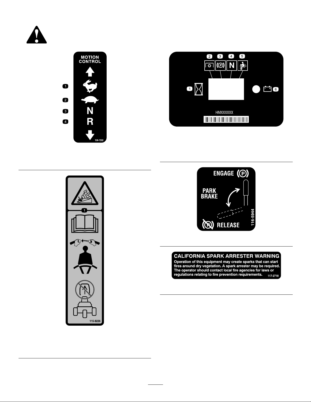
109-7232
1.Fast3.Neutral
2.Slow
4.Reverse
116–5610
1.Hourmeter4.Neutral
2.Powertake-off(PTO)5.Operator-presenceswitch
3.Parkingbrake6.Battery
115-8226
1.Tippinghazard—readtheOperator'smanual;alwayswear
aseatbeltwhenoperating;donotremovetherollover
protectionsystem(ROPS).
116-5944
117–2718
8

125–0214
1.Choke6.Slow
2.Headlight7.Engine—stop
3.Off
4.Headlightandtaillight9.Engine—start
5.Fast
8.Engine—run
127–0363
1.Warning—readtheOperator’sManual.
2.Warning—donotoperatethemachineunlessyouaretrained.6.Warning—wearaseatbelt.
3.Warning—keepbystandersaway.
4.Warning—keepawayfrommovingparts;keepallguardsand
shieldsinplace.
5.Tippinghazard,slopes—donotturnathighspeed;slowdown
andturngradually.
7.Warning—readtheOperator’sManualbeforeperforming
maintenance;1)Engagetheparkingbrakes,2)Removethe
keyfromtheignitionandremovethewirefromthesparkplug.
9

127–0365
1.Pressuptoraisethe
attachment.
2.Pressdowntolowerthe
attachment.
3.ReadtheOperator’s
Manual.
1.ReadtheOperator’sManualforinformationon
fuses—Headlights15A;Attachment10A;Enginestart25A;
Battery20A.
127–0392
1.Warning—keepawayformhotsurfaces.
127–0371
2.ReadtheOperator’sManual.
10

127–7868
1.Warning—donotoperatethemachinewithoutthe
attachmentinstalled.
130–2620
CEonly
1.ReadtheOperator’sManualforinformationonmaintenance.
2.Checkevery8operatinghours.16.Fueltank/lter
3.Oillevel—engine17.Capacity
4.Oillevel—hydraulictank18.Serviceinterval
5.Neutralinterlockswitch19.Filterpartnumber
6.Airlter20.ReadtheOperator’sManualforinformationon
7.Tirepressure(0.48bar)
8.Wheelnuttorque(61to75N-m)22.Left-handdrivenpulley
9.Battery23.Belttensioner
10.Fuel—gasolineonly24.Drivepulley
11.Seatinterlockswitch
12.Checkevery100operatinghours.26.Belttensioner—partnumber(replaceevery800operating
13.Lubrication
14.Engineoil
15.Hydraulicoil
fuses—Headlights15A;Attachment10A;Enginestart25A;
Battery20A.
21.Beltrouting
25.Right-handdrivenpulley
hours)
27.Belt—partnumber(replaceevery800hours)
11
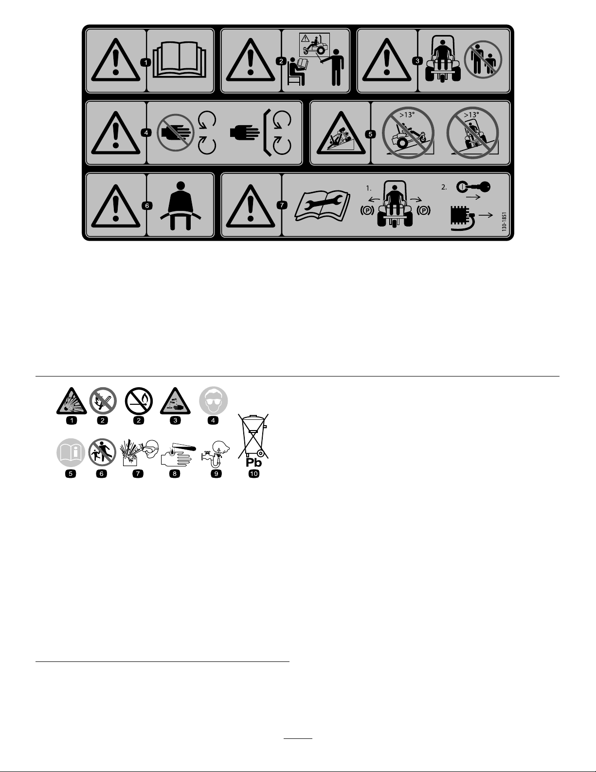
130–1851
CEonly
1.Warning—readtheOperator’sManual.
2.Warning—donotoperatethemachineunlessyouaretrained.6.Warning—wearaseatbelt.
3.Warning—keepbystandersawayfromthemachine.7.Warning—readtheOperator’sManualbeforeperforming
4.Warning—keepawayfrommovingparts;keepallguardsand
shieldsinplace.
5.Tippinghazard—donotdriveupslopesgreaterthan13
degrees;donotdriveacrossslopesgreaterthan13degrees.
maintenance;1)Settheparkingbrake;2)Removethekey
fromtheignitionandremovethewirefromthesparkplug.
BatterySymbols
Someorallofthesesymbolsareonyourbattery
1.Explosionhazard
2.Nore,opename,or
smoking.
3.Causticliquid/chemical
burnhazard
4.Weareyeprotection9.Flusheyesimmediately
5.ReadtheOperator's
Manual.
6.Keepbystandersasafe
distancefromthebattery.
7.Weareyeprotection;
explosivegasescan
causeblindnessandother
injuries
8.Batteryacidcancause
blindnessorsevereburns.
withwaterandgetmedical
helpfast.
10.Containslead;donot
discard.
12

Setup
LooseParts
Usethechartbelowtoverifythatallpartshavebeenshipped.
ProcedureDescription
1
2
3
4
5
6
7
MediaandAdditionalParts
Nopartsrequired
Attachmentandrelatedparts(sold
separately)
Frontweights(asneededper
attachment)
Bolt(5/16x3/4inch)
Nut(5/16inch)
Warningdecal(130-1851)
Servicedecal(130-2620)
Rollbar1
Bolt4
Flangelocknut4
Springwasher
Bracket2
Qty.
Use
–
–
–
1
2
1
1
4
Removetheshippingboard.
Installanattachment.
Installthefrontweights.
Connectthebattery(Model08706TC
only).
ApplytheCEwarningdecal,ifrequired
(Model08706TConly).
ApplytheCEservicedecal,ifrequired
(Model08706TConly).
InstalltheROPS(Model08706TConly).
Description
Operator'sManual
Engineoperator'smanual1
Operatortrainingmaterials
Pre-deliveryinspectionsheet1
PartsCatalog
CerticateofCompliance
Key2
Note:Determinetheleftandrightsidesofthemachinefromthenormaloperatingposition.
Note:Removeanddiscardalltheshippingbracketsandfasteners.
Qty.
1
1
1Usethecatalogtoorderparts.
1
Readthesheetbeforeoperating.
ThecerticateindicatesCEcompliance.
Starttheengine.
Use
13
1
G023667
2
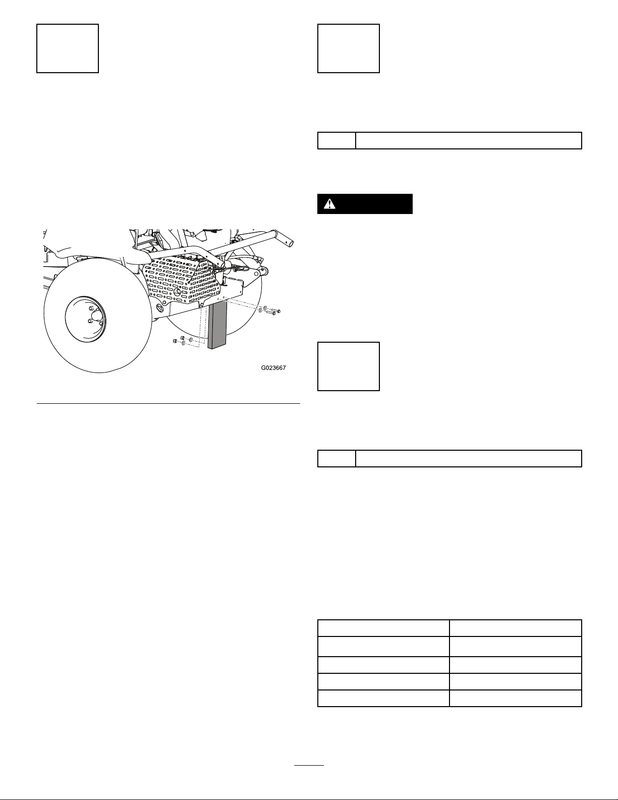
RemovingtheShippingBoard
NoPartsRequired
Procedure
Beforeyoucaninstallanattachmentonthemachine,you
mustremovetheshippingboard.
1.Removethenuts,bolts,andwasherssecuringthe
shippingboardtotherearofthemachine(Figure3).
Figure3
InstallinganAttachment
Partsneededforthisprocedure:
–
Attachmentandrelatedparts(soldseparately)
Procedure
WARNING
Ifyoudrivethemachinewithoutanattachment
installed,itcantipoverandinjuresomeoneor
damageproperty.
Drivethemachineonlyifthereisanapproved
attachmentinstalled.
RefertotheattachmentInstallationInstructionsforinformation
oninstallingtheattachment.
3
2.Discardthefastenersandtheshippingboard.
InstallingtheFrontWeights
Partsneededforthisprocedure:
–
Frontweights(asneededperattachment)
Procedure
ThismachinehasbeendesignedinaccordancewithANSI
B71.4-2012.However,whenyouinstallattachmentsonthe
machine,youmustaddadditionalweighttothemachine,as
specied,tocomplytothestandards.
Usethechartbelowtodeterminetheadditionalweight
required.Themachinecomeswith4weights.Each
attachmentcomeswiththenecessaryadditionalweights,if
required.
Attachment
Flextoothrake4
Flextoothrakewithnishbrush
Naildrag6
Naildragwithnishdragmat
Numberofweightsrequired
6
8
RefertoInstallingandRemovingtheWeights(page21).
14
4
1
G023898
A B
C D
1
4
2
5
3
G023895
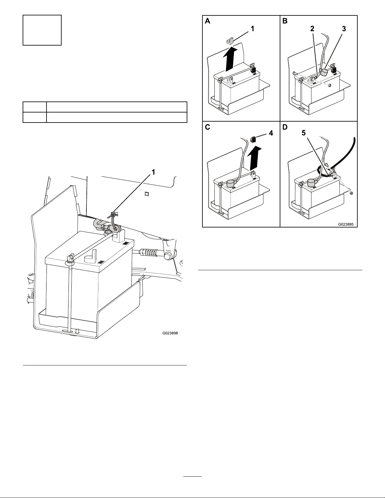
ConnectingtheBattery
Model08706TCOnly
Partsneededforthisprocedure:
1
Bolt(5/16x3/4inch)
2
Nut(5/16inch)
Procedure
1.Cutthecabletiesecuringthebatterycablestothe
frame,anddiscardthecabletie(Figure4).
1.Cabletie
2.Removetheredplasticcoverfromthepositivebattery
terminal(Figure5).
Figure4
Figure5
1.Redcover4.Blackcover
2.Positivecable5.Negativecable
3.Boot
3.Slidetheredbootawayfromtheendofthepositive
batterycable,anduseabolt(5/16x3/4inch)and
anut(5/16inch)tomountthepositivecabletothe
positivebatteryterminal.
4.Slidetheredbootovertheterminalandthefasteners.
5.Removetheblackplasticcoverfromthenegative
batteryterminal.
6.Useabolt(5/16x3/4inch)andanut(5/16inch)
tomountthenegativecabletothenegativebattery
terminal.
15
5
7
ApplyingtheCEWarning
Decal
Model08706TCOnly
Partsneededforthisprocedure:
1
Warningdecal(130-1851)
Procedure
IfthismachinemustbeCEcompliant(Europe),applythe
CEwarningdecal(130-1851)overtheexistingwarningdecal
(127-0363).
6
ApplyingtheCEServiceDecal
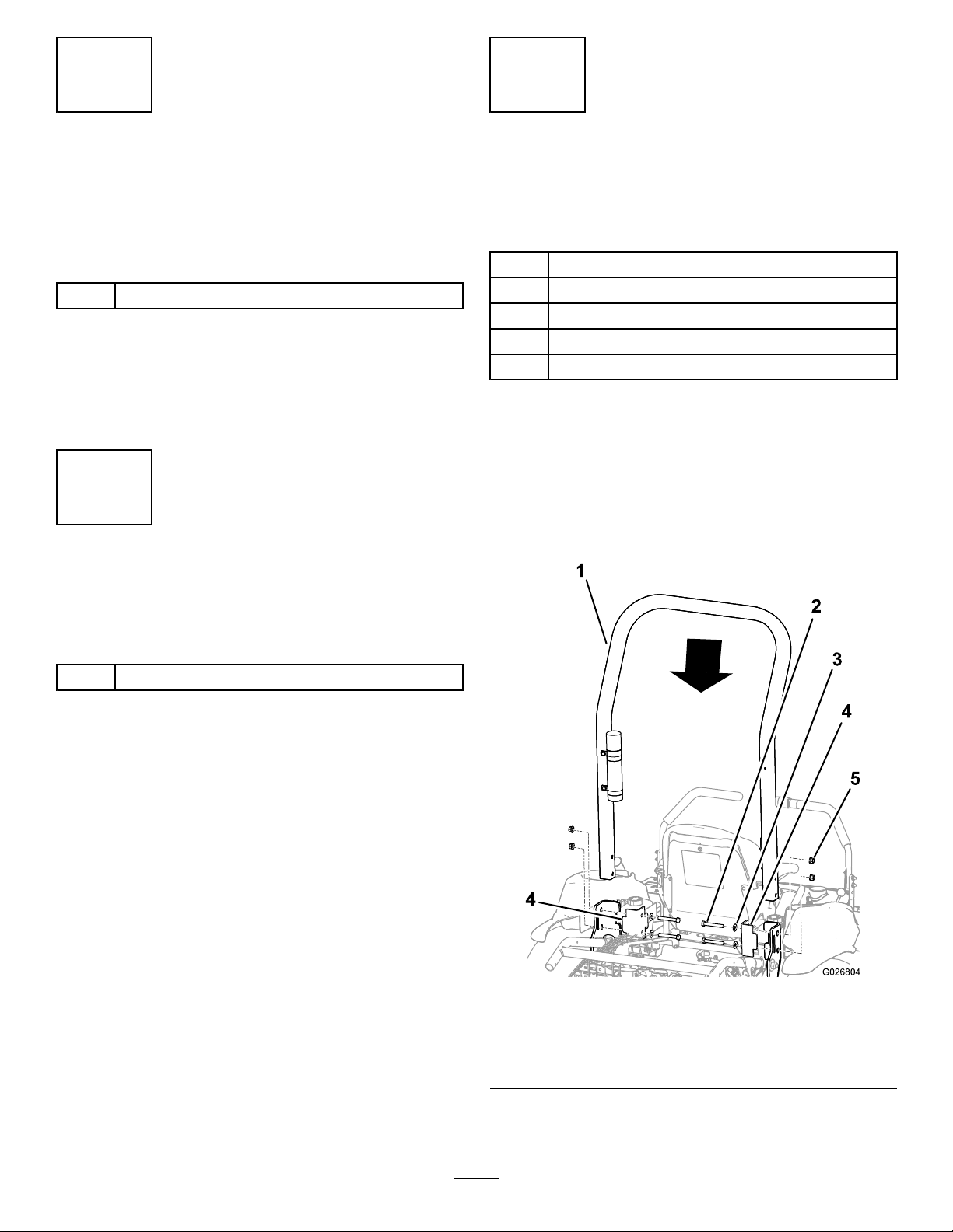
InstallingtheROPS
Model08706TCOnly
Partsneededforthisprocedure:
1Rollbar
4Bolt
4Flangelocknut
4
Springwasher
2Bracket
Procedure
ForModel08706TC,installtheROPSasfollows:
Note:Model08706hastheROPSinstalledatthefactory.
1.Removetherollbarfromthecrate.
2.PlacetherollbaronthemachineasshowninFigure6.
Model08706TCOnly
Partsneededforthisprocedure:
1
Servicedecal(130-2620)
Procedure
IfthismachinemustbeCEcompliant(Europe),applythe
CEservicedecal(130-2620)overtheexistingservicedecal
(127–0371).
Figure6
1.Rollbar
2.Bolt(4)5.Flangelocknut(4)
3.Springwasher(4)
4.Bracket(2)
3.Installthebracketsontheframeofthemachine.
16
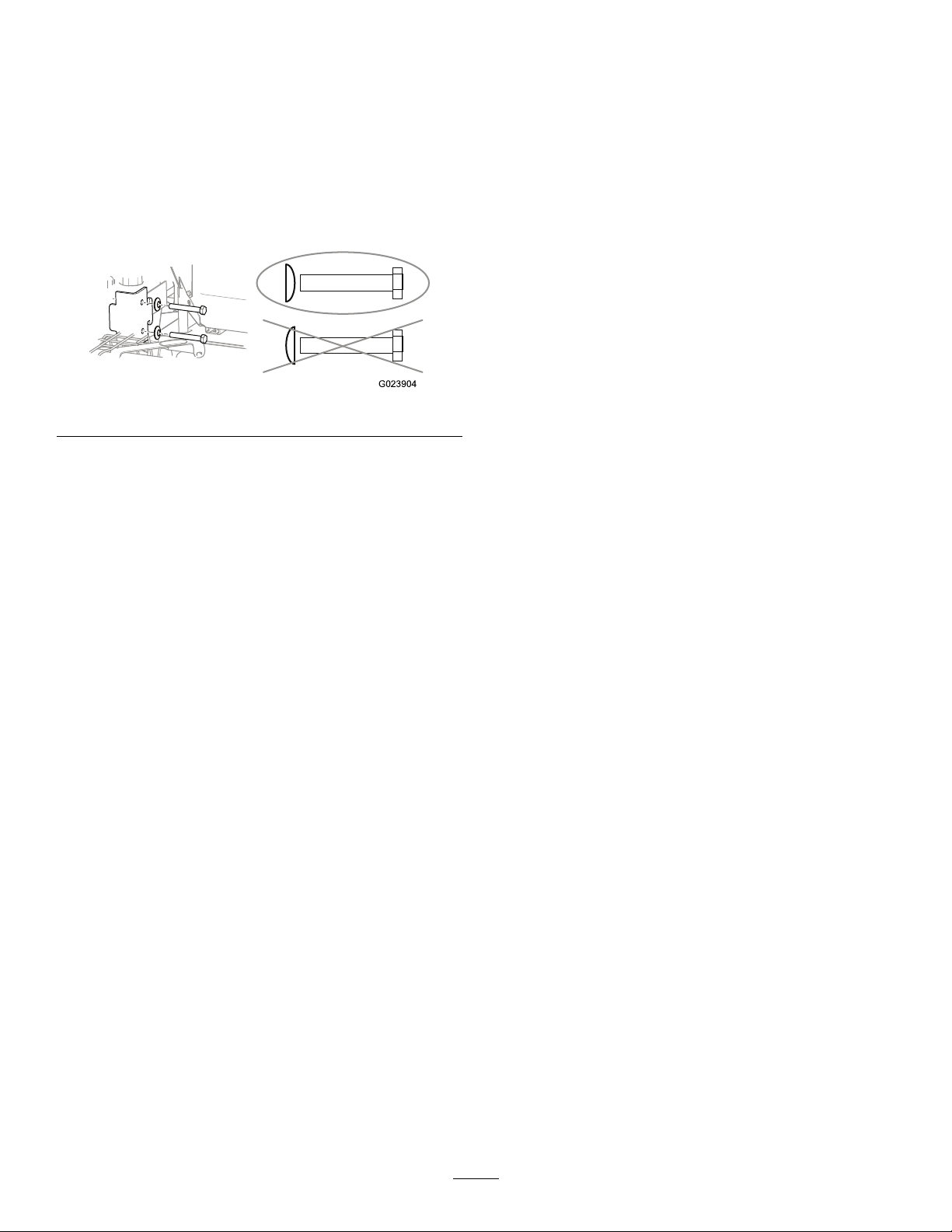
Important:Ensurethatthethrottlecableandthe
G023904
chokecableareoutoftheway ,sothattheydonot
getpinchedbytherollbarorabracket.
4.Aligntheholesinthebrackets,therollbar,andthe
frame.
5.Installabolt,withaspringwasher,througheachhole.
Important:Ensurethateachspringwasheris
positionedsothattheconvexsidefacesthebolt
headasshowninFigure7.
Figure7
6.Installaangelocknutoneachbolt,andtorqueeach
ofthemto102N-m(75ft-lb).
17

ProductOverview
1
2
34
5
6
8
9
7
G023439
1
2
3
4
5
6
G023443
Controls
Figure9
1.Chokecontrol
2.Throttlelever5.Fuses
3.Hourmeter;
safety-interlockdisplay
Figure8
1.Control
handles
2.Raketube5.Battery
3.Fuel-tankcap
4.Attachment
switch
6.Controlpanel
7.Parkingbrake
8.Attachmentlift
9.Engine
ControlHandles
Usethecontrolhandles(Figure8)todrivethemachine
forwardandbackward,andtoturnineitherdirection.
IgnitionSwitch
Theignitionswitch(Figure9),usedtostartandstopthe
engine,has3positions:Off,Run,andStart.Rotatethekey
clockwisetotheStartpositiontostarttheengine.Releasethe
keywhentheenginestarts.Thekeywillmoveautomatically
totheRunposition.Toshuttheengineoff,rotatethekey
counterclockwisetotheOffposition.
ChokeControl
Tostartacoldengine,closethecarburetorchokebypulling
thechokecontrol(Figure9)uptotheClosedposition.After
theenginestarts,regulatethechoketokeeptheengine
runningsmoothly.Assoonaspossible,openthechokeby
pushingthecontroldowntotheOpenposition.
Note:Awarmenginerequireslittleornochoking.
4.Ignitionswitch
6.Attachmentswitch
ThrottleLever
Thethrottlelever(Figure9)controlsthespeedoftheengine.
MovingthethrottleleverforwardtowardtheFastposition
increasestheenginespeed.Movingitbackwardtowardthe
Slowpositiondecreasestheenginespeed.
Note:Thethrottlelevercannotstoptheengine.
18

AttachmentSwitch
1
G020873
G008962
Seat-AdjustmentLever
Toraisetheattachment,presstheupperpartofthe
attachmentswitch(Figure10);tolowertheattachment,press
thelowerpartoftheattachmentswitch.
Whilesittingontheseat,movetheleverinfrontofthe
seat(Figure11)totheleft,andslidetheseattothedesired
position.Releasethelevertolocktheseatintoposition.
Figure11
Figure10
1.Attachmentswitch
Note:Themachinehasadouble-actingliftcylinder.Youcan
applydownpressuretotheattachmentforcertainoperating
conditions.
ParkingBrake
Tosettheparkingbrake(Figure8),pullbackontheleverof
theparkingbrake.Toreleaseit,pushtheleverforward.
HourMeter
Thehourmeter(Figure9)indicatesthetotalhoursof
machineoperation.Thehourmeterrunswheneverthe
ignitionswitchisintheOnposition.
Anoptionalwirelesshourmeterisavailablethroughyour
AuthorizedToroDistributor.Toinstallit,refertoInstallinga
WirelessHourMeter(page31).
19

Specications
Note:Specicationsanddesignaresubjecttochangewithoutnotice.
Machineonly
Weight
Width
Length
Height
Wheelbase
*with4weights,emptyfueltank,andnooperator
**withtheattachmentandweights,emptyfueltank,andnooperator
399kg(880lb)*417kg(920lb)**439kg(970lb)**445kg(980lb)**
147cm(58inches)213cm(84inches)182cm(71.5inches)198cm(78inches)
186cm(73.3inches)226cm(89.0inches)215cm(84.8inches)297cm(1 17inches)
Withextoothrake
Attachments/Accessories
AselectionofToroapprovedattachmentsandaccessoriesis
availableforusewiththemachinetoenhanceandexpand
itscapabilities.ContactyourAuthorizedServiceDealeror
Distributororgotowww .Toro.comforalistofallapproved
attachmentsandaccessories.
Tobestprotectyourinvestmentandmaintainoptimal
performanceofyourToroequipment,countonTorogenuine
parts.Whenitcomestoreliability ,Torodeliversreplacement
partsdesignedtotheexactengineeringspecicationofour
equipment.Forpeaceofmind,insistonT orogenuineparts.
WithnaildragWithnaildragand
nishmat
185cm(73inches)
147cm(58inches)
Operation
Note:Determinetheleftandrightsidesofthemachine
fromthenormaloperatingposition.
ThinkSafetyFirst
Carefullyreadallsafetyinstructionsandsymbolsinthe
safetysection.Knowingthisinformationcouldhelpyouor
bystandersavoidinjury.
DANGER
Operatingonwetgrassorsteepslopescancause
slidingandlossofcontrol.
Wheelsdroppingoveredgescancauserollovers,
whichmayresultinseriousinjury,death,or
drowning.
Readandfollowtherolloverprotectioninstructions
andwarnings.
Toavoidlossofcontrolandpossibilityofrollover:
•Donotoperateneardrop-offsornearwater.
•Reducespeedanduseextremecautionon
slopes.
•Avoidsuddenturnsorrapidspeedchanges.
CAUTION
Thismachineproducessoundlevelsthatcancause
hearinglossthroughextendedperiodsofexposure.
Wearhearingprotectionwhenoperatingthis
machine.
Theuseofprotectiveequipmentforeyes,ears,hands,feet,
andheadisrecommended.
20

G009027
1
2
Figure12
G023729
1.Wearsafetyglasses.
2.Wearhearingprotection.
InstallingandRemovingthe Weights
ThemachinecomplieswiththeANSIB71.4-2012standards
atthetimeofproduction.However,whenthefollowing
attachmentsareinstalledonthemachine,additionalweight
isrequiredtocomplytothestandards.Usethechartbelow
todeterminetheadditionalweightrequired.Themachine
comeswith4weights.Eachattachmentcomeswiththe
necessaryadditionalweights,ifrequired.
Attachment
Flextoothrake4
Flextoothrakewithnishbrush
Naildrag6
Naildragwithnishdragmat
1.Removethe2boltsand2nutssecuringtheexisting
weightsonthefrontofthemachine(Figure13).
Note:Ifthemachineisequippedwiththelightkit,
removethenutandtheboltsecuringthefrontlightto
themachine.Retainalloftheparts;refertotheLight
KitInstallationInstructions.
Numberofweightsrequired
6
8
Figure13
2.Addorremoveweightsasnecessary.
3.Securetheweightswiththe2boltsandthe2nuts.
•Formostoftheattachments,usetheexistingbolts.
•Thenishdragmatincludes2longerbolts
toaccommodatetheadditionalweightsthatit
requires.
Note:Ifthemachineisequippedwiththelightkit,
installthefrontlightbyinsertingtheboltthroughthe
weightsandsecuringitwiththenut;refertotheLight
KitInstallationInstructions.
CheckingtheLevelofthe EngineOil
ServiceInterval:Beforeeachuseordaily—Checkthelevel
oftheengineoil.
ToroPremiumEngineOilisavailablefromyourAuthorized
ToroDistributor.
CrankcaseCapacity:1.8L(1.7USqt)withlterchange
Use4-cycleengineoilthatmeetsorexceedsthefollowing
requirements:
•APIservicecategory:SJ,SL,SM,orhigher
•Viscosity:SAE30;refertothefollowingchartforother
viscosities(Figure14):
Important:Usingmulti-viscosityoils,suchas
10W-30,increasesoilconsumption.Checktheoil
21
levelmorefrequentlywhenusingthem.

G0 2344 5
-20 0 2 0 40 60 80 100 F
-30 -20 -10 0 10 20 30 4 0 C
o
o
S AE 3 0
S AE 5 W-20
S AE 1 0W-30 / S AE 10W-4 0
S AE 4 0
Figure14
1
G023517
G008792
1
2
5
6
7
3
9
10
4
8
1.Positionthemachineonalevelsurface.
2.Stoptheengineandremovethekey.
3.Removethedipstick(Figure15)andwipeitwitha
cleancloth(Figure16).
1.Dipstick
Figure15
Figure16
4.Insertthedipstickintothelltubewithoutthreading
itintotheport.
5.Removethedipstickfromthetubeandchecktheoil
level.Iftheoillevelislow,slowlypouronlyenoughoil
intothelltubetoraisetheoilleveltotheupper-limit
markonthedipstick
Important:Keeptheengineoillevelbetweenthe
upperandlowerlimitsonthedipstick.Engine
failuremayoccurasaresultofrunningtheengine
withtoomuchortoolittleengineoil.
6.Installthedipstickrmlyinplace.
Important:Thedipstickmustbefullyseatedin
thetubetoprovidepropersealingoftheengine
crankcase.Failuretosealthecrankcasemayresult
inenginedamage.
22

FillingtheFuelTank
1
G023449
DANGER
Fueltankcapacity:17L(4.5USgallons)
RecommendedFuel:
•Forbestresults,useonlyclean,fresh(lessthan30days
old),unleadedgasolinewithanoctaneratingof87or
higher((R+M)/2ratingmethod).
•Ethanol:Gasolinewithupto10%ethanol(gasohol)
or15%MTBE(methyltertiarybutylether)byvolume
isacceptable.EthanolandMTBEarenotthesame.
Gasolinewith15%ethanol(E15)byvolumeisnot
approvedforuse.Neverusegasolinethatcontainsmore
than10%ethanolbyvolume,suchasE15(contains15%
ethanol),E20(contains20%ethanol),orE85(contains
85%ethanol).Usingunapprovedgasolinemaycause
performanceproblemsand/orenginedamagewhichmay
notbecoveredunderwarranty.
•Donotusegasolinecontainingmethanol.
•Donotstorefueleitherinthefueltankorfuelcontainers
overthewinterunlessafuelstabilizerisused.
•Donotaddoiltogasoline.
DANGER
Incertainconditionsduringfueling,static
electricitycancauseaspark,whichcanignitethe
fuelvapors.Areorexplosionfromfuelcanburn
youandothersandcandamageproperty.
•Alwaysplacefuelcontainersonthegroundaway
fromyourvehiclebeforelling.
•Donotllfuelcontainersinsideavehicleoron
atruckortrailerbedbecauseinteriorcarpets
orplastictruck-bedlinersmayinsulatethe
containerandslowthelossofanystaticcharge.
•Whenpractical,removefuel-poweredequipment
fromthetruckortrailerandfueltheequipment
withitswheelsontheground.
•Ifthisisnotpossible,thenrefuelsuchequipment
onatruckortrailerfromaportablecontainer,
ratherthanfromafuel-dispensernozzle.
•Ifafueldispensermustbeused,keepthe
nozzleincontactwiththerimofthefueltank
orcontaineropeningatalltimesuntilfuelingis
complete.
Incertainconditions,fuelisextremelyammable
andhighlyexplosive.Areorexplosionfromfuel
canburnyouandothersandcandamageproperty.
•Fillthefueltankoutdoors,inanopenarea,when
theengineiscold.Wipeupanyfuelthatspills.
•Neverllthefueltankinsideanenclosedtrailer.
•Donotllthefueltankcompletelyfull.Addfuel
tothefueltankuntilthelevelis25mm(1inch)
belowthebottomofthellerneck.Thisempty
spaceinthetankallowsthefueltoexpand.
•Neversmokewhenhandlingfuel,andstayaway
fromanopenameorwherefuelfumesmaybe
ignitedbyaspark.
•Storefuelinanapprovedcontainerandkeepit
outofthereachofchildren.Donotbuymore
thana30-daysupplyoffuel.
•Donotoperatewithouttheentireexhaust
systeminplaceandinproperworkingcondition.
WARNING
Gasolineisharmfulorfatalifswallowed.Long-term
exposuretovaporscancauseseriousinjuryand
illness.
•Avoidprolongedbreathingofvapors.
•Keepfaceawayfromnozzleandgastankor
conditioneropening.
•Keepgasawayfromeyesandskin.
1.Cleantheareaaroundthefuel-tankcap(Figure17).
Figure17
1.Fuel-tankcap
2.Removethefuel-tankcap.
23

3.Fillthetanktoabout25mm(1inch)belowthetopof
1
2
3
4
G023450
thetank(bottomofthellerneck).Donotoverll.
4.Installthecap.
5.Wipeupanyfuelthatmayhavespilled,topreventa
rehazard.
Important:Neverusemethanol,gasoline
containingmethanol,orgasoholcontainingmore
than10%ethanol,becausethefuelsystemcould
bedamaged.
Important:Donotmixoilwithfuel.
CheckingtheLevelofthe HydraulicFluid
ServiceInterval:Beforeeachuseordaily—Checkthelevel
ofthehydraulicuid.
Important:Foraccuracy,checkthelevelofthe
hydraulicuidonlywhentheengineandthehydraulic
systemarecold.
Thereservoirsofthemachinearelledatthefactorywith
high-qualityhydraulicuid.Thebesttimetocheckthe
hydraulicuidiswhentheuidiscold.Themachineshould
beinthetransportconguration.Iftheuidlevelisbelow
thetopofthehorizontalpartofthecut-outsightwindowon
therearofthehydraulicreservoirs(Figure18),adduidto
bringtheuidtotheacceptablelevel.Donotoverllthe
reservoirs.Iftheuidlevelisatthetopofthehorizontal
partofthesightwindow,nouidadditionisrequired.The
recommendedreplacementuidis:
MaterialProperties:
Viscosity,ASTMD445cSt@40°C(104°F)55to62
ViscosityIndexASTMD2270
PourPoint,ASTMD97-37°Cto-43°C(-35°Fto-46°F)
IndustrySpecications:
APIGL-4,AGCOPoweruid821XL,FordNewHolland
FNHA-2-C-201.00,KubotaUDT ,JohnDeereJ20C,Vickers
35VQ25,andVolvoWB-101/BM
140to152
Note:Manyhydraulicuidsarealmostcolorless,makingit
difculttospotleaks.Areddyeadditiveforthehydraulic
uidisavailablein20ml(2/3oz)bottles.Onebottleis
sufcientfor15to22L(4to6USgallons)ofhydraulic
uid.Orderpartnumber44-2500fromyourAuthorized
ToroDistributor.
1.Lookattheopeningineachoftheuid-reservoir
brackets,andcheckthelevelofthehydraulicuid.
Note:Theuidlevelshouldbeatthebottomofeach
oftheopenings,asshowninFigure18.
FluidType:ToroPremiumTransmission/HydraulicTractor
FluidorMobiluid
®
424
Capacity:
•Leftside—1.9L(2.0USqt)
•Rightside—2.0L(2.1USqt)
Alternativeuids:Ifthespecieduidisnotavailable,other
universaltractorhydraulicuids(UTHF)maybeused,but
theymustbeonlyconventional,petroleum-basedproducts,
notsyntheticsorbiodegradableuids.Thespecications
mustfallwithinthelistedrangeforallofthefollowing
materialpropertiesandtheuidshouldmeetlistedindustry
standards.Checkwithyouruidsuppliertoseeiftheuid
meetsthesespecications.
Note:Torowillnotassumeresponsibilityfordamage
causedbyimpropersubstitutions,souseonlyproducts
fromreputablemanufacturerswhowillstandbehindtheir
recommendation.
Figure18
1.Hydraulic-uidreservoirs
2.Fluid-reservoircap4.Fluidlevel
3.Bracket
2.Iftheuidlevelislowineitherofthereservoirs,add
uidasfollows:
A.Cleantheareaaroundtheuid-reservoircapsto
preventdebrisfromenteringthesystem(Figure
18).
B.Removethecapsfromthereservoirs.
24

C.Slowlyllthereservoirwiththeappropriate
G016994
1
2
G016995
1
2
hydraulicuiduntilthelevelreachesthebottom
oftheopeningsinthebrackets.
Important:Topreventsystem
contamination,cleanthetopofthe
uidcontainerbeforeopeningit.Ensurethat
thepourspoutandthefunnelareclean.
Important:Donotoverllthereservoirs.
D.Installthereservoircaps.
CheckingtheTirePressure
ServiceInterval:Beforeeachuseordaily
Checkthetirepressurebeforeoperatingthemachine
(Figure19).
Pressure:48kPa(7psi)
SettingtheParkingBrake
WARNING
Theparkingbrakemaynotholdthemachine
parkedonaslopeandcouldcausepersonalinjury
orpropertydamage.
Donotparkonslopesunlessthewheelsare
chockedorblocked.
Tosettheparkingbrake,pullupwardonthehandle(Figure
20).
Figure20
Figure19
1.Valvestem2.Lugnut
TorquingtheWheelLugNuts
ServiceInterval:Aftertherst8hours
Every100hours
Torquethelugsnuts(Figure19)to61to75N-m(45to55
ft-lb).
UsingtheParkingBrake
Alwayssettheparkingbrakewhenyoustopthemachineor
leaveitunattended.
ReleasingtheParkingBrake
Toreleasetheparkingbrake,pushdownwardonthehandle
(Figure21).
Figure21
25

StartingandStoppingthe
1
G023660
Engine
1.Movethecontrolhandlestotheneutral-lockedposition
(Figure22).
5.Tostoptheengine,movethethrottlecontroltothe
Slowposition,andturntheignitionkeytotheOff
position.Removethekeyfromtheswitchtoprevent
accidentalstarting.
Note:Inanemergency,simplyturntheignitionkey
totheOffposition.
UsingtheSafetyInterlock System
CAUTION
Ifthesafetyinterlockswitchesaredisconnectedor
damaged,themachinecouldoperateunexpectedly,
causingpersonalinjury.
•Donottamperwiththeinterlockswitches.
•Checktheoperationoftheinterlockswitches
daily,andreplaceanydamagedswitchesbefore
operatingthemachine.
Thesafetyinterlocksystemisdesignedtopreventtheengine
fromstartingunless:
Figure22
1.Controlhandle
(neutral-lockedposition)
2.Center,unlockedposition5.Frontofthemachine
3.Forward
2.Settheparkingbrake;refertoSettingtheParking
Brake(page25).
3.PullthechokecontrolupwardtotheOnposition
(whenstartingacoldengine),andmovethethrottle
levertotheSlowposition.
Important:Whenoperatingthemachinein
temperatureslessthan0°C(32°F)allowthe
machinetimetowarmupbeforeusingit.This
preventsdamagetothehydraulicsystem.
4.Insertthekeyintotheignitionswitchandrotateit
clockwisetostarttheengine.Releasethekeywhenthe
enginestarts.Regulatethechoketokeeptheengine
runningsmoothly.
Important:Topreventoverheatingofthestarter
motor,donotkeeptheignitionkeyintheStart
positionforlongerthan10seconds.After10
secondsofcontinuouscranking,wait60seconds
beforeusingthestartermotoragain.
4.Backward
•Theparkingbrakeisengaged.
•Themotion-controlleversareintheneutral-locked
position
Thesafetyinterlocksystemalsostopstheenginewhenyou
movethecontrolhandlesoutoftheneutral-lockedposition
whileyouareoutoftheseatorwhiletheparkingbrakeisset.
Thehourmeterhassymbolstonotifyyouwhentheinterlock
componentisinthecorrectposition.Whenthecomponentis
inthecorrectposition,atriangleappearsinthecorresponding
location(Figure23).
Figure23
1.Trianglesappearwhentheinterlockcomponentsareinthe
correctposition.
Note:ThePTO(powertake-off)interlockisnotusedon
thismachine.
26

TestingtheSafetyInterlockSystem
ServiceInterval:Beforeeachuseordaily
Ifthesafetyinterlocksystemdoesnotoperateasdescribed
below,haveanAuthorizedT oroDistributorrepairit
immediately.
1.Sitontheseat,movethecontrolhandlestotheneutral
position,andsettheparkingbrake.
2.Starttheengine.
3.Getofftheseatandslowlymoveeachcontrolhandle
forwardandbackward.
Note:Theengineshouldstopin1to3secondsafter
movingeithercontrolhandleineitherdirection.Ifit
doesnot,correcttheproblem.Repeatsteps2and3for
theothercontrolhandle.
4.Sittingontheseat,engagetheparkingbrake.Move
eithercontrolhandleoutoftheneutral-lockedposition.
Trystartingtheengine;theengineshouldnotcrank.
Repeatthisstepfortheothercontrolhandle.
DrivingtheMachine
UsingtheControlHandles
CAUTION
Operatingthemachinedemandsattentionto
preventtippingorlossofcontrol.
•Usecarewhenenteringandleavingsandtraps.
•Useextremecautionaroundditches,creeks,or
otherhazards.
•Usecautionwhenoperatingthemachineona
steepslope.
•Reduceyourspeedwhenmakingsharpturnsor
whenturningonhillsides.
•Avoidsuddenstopsandstarts.
•Donotgofromreversetofullforwardwithout
rstcomingtoacompletestop.
CAUTION
Themachinecanspinveryrapidly.Ifyoumisuse
thecontrolhandles,youmaylosecontrolofthe
machineandinjuresomeoneordamagethe
machineorotherproperty .
Figure24
1.Controlhandle
(neutral-lockedposition)
2.Center,unlockedposition5.Frontofthemachine
3.Forward
4.Backward
DrivingtheMachineForward
Note:Theenginestopsifyoumovethecontrolhandles
whiletheparkingbrakeisset.
1.Releasetheparkingbrake;refertoReleasingthe
ParkingBrake(page25).
2.Movethecontrolhandlestothecenter,unlocked
position.
3.Togoforward,slowlypushthecontrolhandlesforward
(Figure25).
Tostopthemachine,movethecontrolhandlestothe
neutralposition.
•Usecautionwhenmakingturns.
•Slowthemachinedownbeforemakingsharp
turns.
27

G0 2344 1
Figure25
G0 2344 2
DrivingtheMachineBackward
1.Ensurethattheattachmentisinthedesiredposition.
2.Movethecontrolhandlestothecenter,unlocked
position.
3.Togobackward,lookbehindandslowlypullthe
controlhandlesbackward(Figure26).
Figure26
RakingaSandTrap
Readthisentiresectiononrakingbeforerakingasandtrap.
Therearemanyconditionsthatdeterminetheadjustments
necessary.Thetextureanddepthofthesand,moisture
content,weeds,andtheamountofcompactionareallfactors
thatcanvaryfromcoursetocourse,orevenfromtraptotrap
onthesamecourse.Maketheadjustmentsontherakefor
optimumresultsinyourparticulararea.
LearningHowtoRake
Practicerakinginalargeandleveltraponthecourse.Practice
startingandstopping,turning,raisingandloweringtherake,
enteringandleavingthetrap,etc.Practiceatamoderate
enginespeedandaslowgroundspeed.Thistraininghelps
theoperatortogaincondenceintheperformanceofthe
machine.
Therecommendedpatternforrakingatrapisshownin
Figure27.Thispatternavoidsunnecessaryoverlap,keeps
compactiontoaminimum,andleavesaneat,attractive
patternonthesand.Thisisthemostefcientrakingmethod,
however,itisimportanttovarytherakingpatternregularlyto
reducethechanceofcreatingawashboardeffect.
28

1
2
G003409
Figure27
performancecloselysothatyoucannoticeandcorrectminor
difculties,whichcouldleadtomajorproblems.Inspectthe
machinefrequentlyduringthebreak-inperiod,forsignsofoil
leakage,loosefasteners,oranyothermalfunction.
PushingorTowingthe Machine
WARNING
Handsmaybecomeentangledintherotatingdrive
componentsbelowtheenginedeck,whichcould
resultinseriousinjury.
Stoptheengine,removethekey,andallow
allmovingpartstostopbeforeaccessingthe
bypass-valvelevers.
1.Enteratrapstraightinto
thelongdimensionina
levelarea.
Enterthetrapstraightintothelongdimension,wherethe
bankistheleaststeep.Drivethroughthecenterofthetrap
almosttotheend,turntoeitherdirectionassharpasyoucan,
andcomebackrightnexttotherstpass.Spiraloutwardas
showninFigure27,andleavethetrapatarightangleina
levelarea.
Leavesteep,shortbanksandsmallpocketsfortouch-upwith
ahandrake.
2.Exitatrapatarightangle
inalevelarea.
EnteringandLeavingtheTrap
Whenenteringthetrap,donotlowertherakeuntilitis
overthesand.Thisavoidscuttingtheturfordragginggrass
clippingsorotherdebrisintothetrap.Lowertherakewhile
themachineismoving.
Whenleavingthetrap,startraisingtherakewhenthefront
wheelleavesthetrap.Asthemachinemovesout,therakewill
beliftingandwillnotdragsandoutontothegrass.
Throughexperienceandpractice,theoperatorwillsoon
understandtherequiredtimingforenteringandleavingthe
trapproperly.
BreakingintheMachine
Newenginestaketimetodevelopfullpower.Drivesystems
havemorefrictionwhentheyarenew ,placingadditionalload
ontheengine.
WARNING
Theengineandhydrostatictransmissionscan
becomeveryhotandcausesevereburns.
Allowtheengineandhydrostatictransmissionsto
coolcompletelybeforeaccessingthebypass-valve
levers.
Important:Donottowthemachineforlongdistances
orathighspeeds.Doingsocoulddamagethemachine.
Youcantowthemachineslowlyfromthegrooming
surfacetotheon-sitetrailer.
Thebypass-valveleversarelocatedonthetopofeach
hydrostatictransmission.
Important:Makesurethatthebypass-valveleversarein
thefullyforwardpositionwhenoperatingthemachine,
orseveredamagetothehydraulicsystemcanoccur.
1.Stopthemachineonalevelsurfaceandturnthe
ignitionkeytotheOffposition.
2.Movetheleverstotheneutral-lockedposition,setthe
parkingbrake,andremovethekey.
3.Fromunderneaththemachine,rotatethebypass-valve
levers(Figure28andFigure29)sothattheypoint
inward,towardthecenterofthemachine(Figure30),
andreleasetheparkingbrake;refertoReleasingthe
ParkingBrake(page25).
Note:Thisallowsthehydraulicuidtobypassthe
pumps,enablingthewheelstoturnfreely.
Allowtherst8hoursofoperatingtimeforthebreak-in
period.
Sincethersthoursofoperationarecriticaltofuture
dependabilityofthemachine,monitorthefunctionsand
29

1
G023553
1
G023554
G023555
1
2
TransportingtheMachine
Useaheavy-dutytrailerortrucktotransportthemachine.
Ensurethatthetransportvehicle(trailerortruck)hasall
thenecessarybrakes,lighting,andmarkingasrequiredby
law .Carefullyreadandunderstandallthesafetyinstructions.
Knowingthisinformationcouldhelpyou,yourfamily,pets,
orbystandersavoidinjury.
WARNING
Figure28
Leftbypass-valvelever
Figure29
Rightbypass-valvelever
Drivingonthestreetorroadwaywithout
turnsignals,lights,reectivemarkings,ora
slow-moving-vehicleemblemisdangerousandcan
leadtoaccidentscausingpersonalinjury .
Donotdrivethemachineonapublicstreetor
roadway.
Useextremecautionwhenloadingthemachineontothe
transportvehicle.Useafull-widthrampthatiswideenough
toextendbeyondthereartires,insteadofindividualramps
foreachsideofthemachine.Theattachmentservesasastop
fortippingbackward.Usingafull-widthrampprovidesa
largersurfacefortheattachmenttocontactifthemachine
startstotipbackward.
Ensurethattherampislongenoughsothattheangledoes
notexceed13degrees.Asteeperanglemaycausemachine
componentstogetcaughtasthemachinemovesfromthe
ramptothetransportvehicle.Steeperanglesmayalsocause
themachinetotipbackward.Ifloadingonornearaslope,
positionthetransportvehiclesothatitisonthedownside
oftheslopeandtherampextendsuptheslope;thiswill
minimizetherampangle.Thetransportvehicleshouldbeas
levelaspossible.
Figure30
1.Inwardtopushortowthe
machine
4.Whenyouarenishedpushingortowingthemachine,
2.Forwardtodrivethe
machine
rotatethebypass-valveleverssothattheypointtoward
thefrontofthemachine,toallowthemachinetodrive
(Figure30).
30

WARNING
1
G023892
1 2
G023736
Loadingthemachineontoatransportvehicle
increasesthepossibilityoftippingoverandcould
causeseriousinjuryordeath.
•Alignthemachineappropriately,andslowly
drivestraightuptheramp.
•EnsurethattheROPSisinstalledandsecure.
•Ensurethatthereisadequatespaceforthe
machine.
•Donotexceeda13-degreeanglebetweenthe
rampandthegroundorbetweentherampand
thetransportvehicle.
•Avoidsuddenaccelerationwhiledrivingthe
machineuparamp,toavoidtippingbackward.
•Avoidsuddendecelerationwhilebacking
themachinedownaramp,toavoidtipping
backward.
•Ensurethatanattachmentisinstalledandinthe
raisedpositionwhenloadingthemachineonto
atransportvehicle.
Figure32
1.Tie-downpoints
InstallingaWirelessHour Meter
Anoptionalwirelesshourmeterisavailablethroughyour
AuthorizedToroDistributor.
RefertotheWirelessHourmeterSystemguide.
1.Removethecontrolpanel(Figure33).
Figure31
1.Trailer3.Notgreaterthan13
2.Full-widthramp4.Full-widthramp—side
Usethetie-downpointsonthemachine(Figure32)to
securelyfastenthemachinetothetransportvehiclewith
properstraps,chains,cable,orropes.
degrees
view
Figure33
1.Controlpanel2.Screw(4)
2.Locatethewirelesshour-meterjumper.
Note:Thejumperislabeled.
31

3.Attachthewirelesshourmeter.
4.Tiethewirelesshourmetertotheexistingharnessto
preventexcessivemotionintheconsole.
5.Installthecontrolpanel.
OperatingTips
•Ifthesandisdeepenough,youcanrakerightuptothe
edgeofthetrapinlevelareas.
•Ifthesandfeathersouttotheturf,stayfarenoughaway
fromtheedgetoavoiddisturbingtheunderlyingsoil.
•Donotraketooclosetoashort,steepbank.Thesand
willmerelyowdownintothebottomofthetrap.
•Sometouch-upwithahandrakemaybenecessaryon
steepbanks,smallpockets,etc.
32

Maintenance
Note:Determinetheleftandrightsidesofthemachinefromthenormaloperatingposition.
CAUTION
Ifyouleavethekeyintheignitionswitch,someonecouldaccidentlystarttheengineandseriouslyinjure
youorotherbystanders.
Removethekeyfromtheignitionbeforeyoudoanymaintenance.
RecommendedMaintenanceSchedule(s)
MaintenanceService
Interval
Aftertherst8hours
Beforeeachuseordaily
Every100hours
Every200hours
Every300hours
MaintenanceProcedure
•T orquethewheellugnuts.
•Changetheengineoil.
•Changetheengineoillter.
•Changethehydraulicuidandlters.
•Checktheleveloftheengineoil.
•Checkthelevelofthehydraulicuid.
•Checkthetirepressure.
•Checkthesafetyinterlocksystem.
•Checktheconditionofthehydrauliclinesandhoses.
•Inspectandcleanthemachine.
•T orquethewheellugnuts.
•Greasethemachine.
•Changetheengineoil(moreofteninextremelydustyordirtyoperatingconditions).
•Changetheengineoillter(moreofteninextremelydustyordirtyoperating
conditions).
•Servicethesparkplugs.
•Checkthebatterycableconnections.
•Replacetheairlter(moreoftenindustyconditions).
•Replacethecarbon-canisterlter.
•Checkandadjustthevalveclearance.
•Cleanandlapthevalve-seatingsurface.
Every400hours
Every800hours
•Changethehydraulicuidandlters.
•Replacethefuellter.
Important:Refertoyourengineoperator'smanualforadditionalmaintenanceprocedures.
33

DailyMaintenanceChecklist
Duplicatethispageforroutineuse.
Fortheweekof: MaintenanceCheckItem
Mon.Tues.Wed.Thurs.Fri.
Checkthesafetyinterlock
operation.
Checktheparkingbrake
operation.
Checktheoperationofthe
controlhandles.
Checkthefuellevel.
Checktheengineoillevel.
Checktheairltercondition.
Cleantheenginecooling
ns.
Checkunusualengine
noises.
Checkunusualoperating
noises.
Checkthelevelofthe
hydraulicuid.
Checkhydraulichosesfor
damage.
Checkforuidleaks.
Checkthetirepressure.
Checktheinstrument
operation.
Lubricateallgreasettings.
Touch-updamagedpaint.
1.Immediatelyaftereverywashing,regardlessoftheintervallisted.
1
Sat.Sun.
NotationforAreasofConcern
Inspectionperformedby:
ItemDate
Information
34

Premaintenance
2
1
G023550
G023436
Lubrication
Procedures
GreasingtheMachine
LiftingtheMachine
WARNING
Mechanicalorhydraulicjacksmayfailtosupport
themachineandcauseseriousinjury .
Usejackstandswhensupportingthemachine.
RefertoFigure34forthesupportpoints.
ServiceInterval:Every100hours
GreaseType:No.2lithiumgrease
Greaseeachgreasettinglocatedonthefrontwheelhub,the
belttensioner,andtheattachmentliftasfollows:
1.Wipethegreasettingcleansothatforeignmatter
cannotbeforcedintothebearingorbushing.
2.Attachagreaseguntothetting,andpumpgrease
intothetting.
3.Wipeupanyexcessgrease.
•Frontwheelbearing(1)—Figure35
Figure34
1.Supportpoints(rear)2.Supportpoints(front)
Figure35
•Belttensioner(1)—Figure36
35

G023437
Figure36
G023438
G0 2344 5
-20 0 2 0 40 60 80 100 F
-30 -20 -10 0 10 20 30 4 0 C
o
o
S AE 3 0
S AE 5 W-20
S AE 1 0W-30 / S AE 10W-4 0
S AE 4 0
EngineMaintenance
ServicingtheEngineOiland Filter
ChangingtheEngineOil
ServiceInterval:Aftertherst8hours—Changetheengine
oil.
Every100hours—Changetheengineoil(moreoften
inextremelydustyordirtyoperatingconditions).
ToroPremiumEngineOilisavailablefromyourAuthorized
ToroDistributor.
CrankcaseCapacity:1.66L(1.75USqt)withlterchange
Use4-cycleengineoilthatmeetsorexceedsthefollowing
requirements:
•APIservicecategory:SJ,SL,SM,orhigher
•Attachmentlift(4)—Figure37
Figure37
•Viscosity:SAE30;refertothefollowingchartforother
viscosities(Figure38):
Important:Usingmulti-viscosityoils,suchas
10W-30,increasesoilconsumption.Checktheoil
levelmorefrequentlywhenusingthem.
Figure38
1.Runtheengineforafewminutestowarmtheoil.
2.Parkthemachineonalevelsurface,stoptheengine,set
theparkingbrake,andremovethekey.
3.Removethedrainplug(Figure40)andlettheoildrain
intoasuitablecontainer.Whentheoilstopsdraining,
installthedrainplug.
Note:Insertapieceofpaperorlightcardboardinto
thedrainholetochanneltheoilawayfromtheengine
mountingplate(Figure39).
36

Figure39
1
2
3
G023444
G008796
2
3
4
5
6
1
1.Cardboard
2.Drainplug
3.Drainhole
Figure41
5.Pourfreshoilintothelltube.
6.Starttheengineandletitrunforabout3minutes,and
ensurethattherearenoleaks.
7.Stoptheengine.
8.Checktheoillevel,andaddoilifnecessary.
9.Installthedipstick.
10.Disposeoftheusedoilaccordingtolocalcodes.
ChangingtheEngineOilFilter
1.Drainplug3.Dipstick
2.Oillter
4.Removethedipstickandwipeitwithacleancloth
(Figure41).
Figure40
ServiceInterval:Aftertherst8hours—Changetheengine
oillter.
Every100hours—Changetheengineoillter(more
ofteninextremelydustyordirtyoperatingconditions).
1.Runtheengineforafewminutestowarmtheoil.
2.Parkthemachineonalevelsurface,stoptheengine,set
theparkingbrake,andremovethekey.
3.Draintheengineoil;refertoChangingtheEngineOil
(page36).
4.Placeadrainpanundertheoillter,andturnthelter
counterclockwisetoremoveit(Figure42).
37

G008748
3/4
1
2
3
4
5
6
ServicingtheAirCleaner
1
2 3
4
G023446
ReplacingtheAirFilter
ServiceInterval:Every200hours(moreoftenindusty
conditions).
Note:Changingtheairlterbeforeitisnecessaryonly
increasesthechanceofdirtenteringtheenginewhenthe
lterisremoved.
1.Parkthemachineonalevelsurface,stoptheengine,set
theparkingbrake,andremovethekey.
2.Releasethelatchessecuringtheair-cleanercovertothe
air-cleanerbody(Figure43).
Figure42
5.Applyalightcoatofcleanoiltothegasketofthenew
lter.
6.Installthenewlter,turningitbyhanduntilthegasket
contactsthelteradapter;thentightenit3/4turn
more.
Important:Donotovertightenthelter.
7.Checktheoillevel;refertoCheckingtheLevelofthe
EngineOil(page21).
8.Ifnecessary,addoilintothelltube.
9.Starttheengineandletitrunforabout3minutes,and
ensurethattherearenoleaks.
10.Stoptheengine.
11.Checktheoillevel,andaddoilifnecessary.
Note:Thelterholdssomeoil,sotheoillevelmay
decreasewheninstallinganewlter.
12.Installthedipstick.
13.Disposeoftheusedoilaccordingtolocalcodes.
Figure43
1.Latch(2)3.Cover
2.Airlter
3.Removethecoverfromtheair-cleanerbody.
4.Removetheoldlter,andinstallthenewlter.
Note:Inspectthenewlterforshippingdamage,
checkingthesealingendofthelterandthebody .
Donotuseadamagedelement.Insertthenewlter
byapplyingpressuretotheouterrimoftheelement
toseatitinthecanister.Donotapplypressuretothe
exiblecenterofthelter.
Note:Donotcleantheusedelement,becauseitcan
damagetheltermedia.
5.Cleanthedirt-ejectionportlocatedintheremovable
cover.
6.Installthecoversothatthedirt-ejectionportpoints
downward.
4.Dirt-ejectionport
38

7.Securethelatches.
1
G023447
G019300
1 2
4
3
8.Checkthewholeintakesystemforleaks,damage,or
loosehoseclamps.
ServicingtheSparkPlugs
ServiceInterval:Every100hours
Type:NGKBPR4ES(orequivalent)
Gap:0.76mm(0.030inch)
Note:Thesparkplugsusuallylastalongtime;however,you
shouldcheckthemwhenevertheenginemalfunctions.
1.Cleantheareaaroundeachofthesparkplugssothat
foreignmattercannotfallintothecylinderswhenyou
removethesparkplugs.
Figure44
1.Spark-plugwires
2.Disconnectthespark-plugwiresfromthesparkplugs,
andremovetheplugsfromthecylinderheads.
Figure45
1.Sideelectrode
2.Centerelectrode4.0.76mm(0.030inch)gap
3.Insulator
CheckingandAdjustingthe ValveClearance
ServiceInterval:Every300hours
Thisproceduremustbeperformedwiththepropertools.See
yourauthorizedKawasakienginedealerforservice,unless
youhavetheproperequipmentandadequatemechanical
prociency.
CleaningandLappingthe Valve-SeatingSurface
ServiceInterval:Every300hours
Thisproceduremustbeperformedwiththepropertools.See
yourauthorizedKawasakienginedealerforservice,unless
youhavetheproperequipmentandadequatemechanical
prociency.
3.Checktheconditionofthesideelectrode,thecenter
electrode,andtheinsulatortoensurethatthereisno
damage.
Important:Replacethesparkplugsiftheyare
cracked,fouled,dirty,orotherwisemalfunctioning.
Donotcleantheelectrodes,becausegritentering
thecylindermaydamagetheengine.
4.Foreachsparkplug,setthegapbetweenthecenter
electrodeandthesideelectrodeto0.76mm(0.030
inch);refertoFigure45.Installeachofthecorrectly
gappedsparkplugswithagasketseal,andtightenthe
plugsto22N-m(16ft-lb).
39

FuelSystem
G023891
1
2
3
1
G023990
1
G023448
G008963
12
3
Maintenance
ReplacingtheFuelFilter
ServiceInterval:Every800hours
Thefuellinehasanin-linelter.Replaceitasfollows:
ReplacingtheCarbon-Canister Filter
ServiceInterval:Every200hours
1.Removethefastenerssecuringtheseatassemblytothe
machine.
1.Loosenthehoseclamponthecarburetorsideofthe
lter,andremovethefuellinefromthelter(Figure
48andFigure49).
Figure48
1.Fuellter
Figure46
1.Seatassembly3.Washer(4)
2.Bolt(4)
2.Disconnectthelterfromthecarboncanister(Figure
47).
1.Fuellter
Figure47
1.Carbon-canisterlter
3.Connectthenewltertothecarboncanister.
4.Installtheseatsupportplateandtheseat.
2.Hoseclamp(2)
2.Placeadrainpanunderthelter,loosentheremaining
hoseclamp,andremovethelter.
3.Slidethehoseclampsontotheendsofthefuellines.
4.Pushthefuellinesontothenewfuellter,andsecure
themwiththehoseclamps.
Figure49
3.Fuelline
40

Note:Installthenewlterwiththearrowonthelter
bodypointingawayfromthefueltank(towardthe
carburetor).
ElectricalSystem
Maintenance
WARNING
CALIFORNIA
Proposition65Warning
Batteryposts,terminals,andrelated
accessoriescontainleadandleadcompounds,
chemicalsknowntotheStateofCalifornia
tocausecancerandreproductiveharm.
Washhandsafterhandling.
Jump-StartingtheMachine
1.Removeanycorrosionfromthebatteryterminals,
andensurethattheconnectionsaretightbefore
jump-startingthemachine.
Important:Corrosionorlooseconnectionscan
causeunwantedelectricalvoltagespikesatany
timeduringthejump-startingprocedure,which
coulddamagetheengine.
Donotattempttojump-startthemachineifthe
batteryterminalsarelooseorcorroded.
DANGER
Jump-startingaweakbatterythatiscracked
orfrozen,orhasalowelectrolytelevelor
anopen/shortedbatterycell,cancausean
explosionresultinginseriouspersonalinjury.
Donotjump-startaweakbatteryifthese
conditionsexist.
2.Ensurethattheboosterbatteryisagood,fullycharged
lead-acidbatterywithatleast12.6V .Useproperlysized
jumpercableswithshortlengthstoreducethevoltage
dropbetweenthesystems.Makesurethatthecables
arecolorcodedorlabeledforthecorrectpolarity.
Note:Besurethattheventcapsaretightandlevel.
Placeadampcloth,ifavailable,overtheventcapson
eachbattery.Besurethatthemachinesdonottouch
andthatbothelectricalsystemsareturnedoffandhave
thesameratedsystemvoltage.Theseinstructionsare
fornegative-groundsystemsonly .
3.Connectthepositive(+)cabletothepositive(+)
terminalofthedischargedbatterythatiswiredtothe
starterorsolenoidasshowninFigure50.
41

Figure50
g0131 17
1
2
1
2 3 4
G023451
ReplacingtheFuses
Thefuseblock(Figure52)islocatednearthecontrolpanel.
1.Positive(+)cableon
dischargedbattery
2.Positive(+)cableon
boosterbattery
3.Negative(–)cableonthe
boosterbattery
4.Negative(–)cableonthe
engineblock
5.Boosterbattery
6.Dischargedbattery
7.Engineblock
4.Connecttheotherendofthepositivecabletothe
positiveterminaloftheboosterbattery.
5.Connecttheblacknegative(–)cabletotheother
terminal(negative)oftheboosterbattery.
6.Makethenalconnectionontheengineblock(not
onthenegativebatterypost)ofthemachinewiththe
dischargedbattery,awayfromthebattery,andstand
back(Figure51).
Figure52
1.Lights(soldseparately)
2.Attachment—10A
3.Enginestart—25A
4.Battery—20A
Toreplaceafuse,removeitbysimplypullingitoutfromthe
fuseblock,andinstallanewfuse
Important:Alwaysuseafuseofthesametypeand
amperageastheoneyouarereplacing;otherwise,you
coulddamagetheelectricalsystem.Refertothedecal
onthebackoftheseatforthefunctionandamperage
ofeachfuse.
ServicingtheBattery
ChargingtheBattery
WARNING
Chargingthebatteryproducesgasesthatcan
explode,seriouslyinjuringyouorbystanders.
Figure51
1.Engineblock
2.Negative(–)cable
7.Starttheengine,andremovethecablesinthereverse
orderofconnection.
Note:Disconnectthecableconnectedtotheengine
block(blackcable)rst.
Neversmokenearthebattery,andkeepsparksand
amesawayfromthebattery.
Important:Alwayskeepthebatteryfullycharged.This
isespeciallyimportanttopreventbatterydamagewhen
thetemperatureisbelow0°C(32°F).
1.Chargethebatteryfor10to15minutesat25to30
A,or30minutesat10A.
2.Whenthebatteryisfullycharged,unplugthecharger
fromtheelectricaloutlet,anddisconnectthecharger
leadsfromthebatteryposts(Figure53).
3.Installthebatteryinthemachineandconnectthe
batterycables;refertoInstallingtheBattery(page44).
42

Important:Donotrunthemachinewiththe
1 2
43
G023653
batterydisconnected;electricaldamagemay
occur.
Figure53
3.Disconnectthenegative(black)groundcablefromthe
batterypost.
WARNING
Incorrectbatterycableroutingcoulddamage
themachineandcables,causingsparks.
Sparkscancausethebatterygasestoexplode,
resultinginpersonalinjury.
•Alwaysdisconnectthenegative(black)
batterycablebeforedisconnectingthe
positive(red)cable.
•Alwaysconnectthepositive(red)battery
cablebeforeconnectingthenegative
(black)cable.
1.Positivebatterypost
2.Negativebatterypost
Ifthebatterynolongerholdsacharge,replaceit;referto
RemovingtheBattery(page43)andInstallingtheBattery
(page44).
3.Red(+)chargerlead
4.Black(-)chargerlead
RemovingtheBattery
1.Movethemachinetoalevelsurface,settheparking
brake,stoptheengine,andremovethekey.
2.Removethewingnutsandwasherssecuringthebattery
hold-down(Figure54).
WARNING
Batteryterminalsormetaltoolscouldshort
againstmetalmachinecomponents,causing
sparks.Sparkscancausethebatterygasesto
explode,resultinginpersonalinjury.
•Whenremovingorinstallingthebattery,
donotallowthebatteryterminalstotouch
anymetalpartsofthemachine.
•Donotallowmetaltoolstoshortbetween
thebatteryterminalsandmetalpartsof
themachine.
4.Slidetheredterminalbootoffthepositive(+)battery
terminal,andremovethepositive(red)batterycable.
5.Removethebattery.
Figure54
43

InstallingtheBattery
1 2
43
G023659
1.Placethebatteryinthetray.
Ifcorrosionoccursatthebatteryterminals,disconnectthe
cables,negative(-)cablerst,andscrapetheclampsand
terminalsseparately.Connectthecables,positive(+)cable
rst,andcoattheterminalswithpetroleumjelly.
Figure55
2.Installthepositive(red)batterycabletothepositive
(+)batteryterminal,andtightenthenutontothebolt.
Important:Theredcablemaybecoveredbya
wireloom.Thepositivecableistheonewiththe
redboot.
3.Installthenegative(black)groundcabletothenegative
(-)batteryterminal,andtightenthenutontothebolt.
4.Slidetheredterminalbootontothepositive(+)battery
post.
5.Installthehold-down,andsecureitwiththewingnuts
andwashers.
CheckingandCleaningtheBattery
ServiceInterval:Every100hours—Checkthebatterycable
connections.
Keepthetopofthebatteryclean.Ifthemachineisstoredin
alocationwheretemperaturesareextremelyhigh,thebattery
willdischargemorerapidlythanifthemachineisstoredin
acoolerlocation.
Keepthetopofthebatterycleanbywashingitwithabrush
dippedinammoniaorasolutionofsodiumbicarbonate.
Flushthetopsurfacewithwateraftercleaning.Donot
removethellcapwhilecleaningthebattery.
Thebatterycablesmustbetightontheterminalstoprovide
goodelectricalcontact.
44

DriveSystem
1
2
G023556
2 64 51
G023453
3
Maintenance
AdjustingtheTracking
ReplacingtheDriveBeltand theTensionerPulley
1.Parkthemachineonalevelsurface,stoptheengine,
removethekey ,andwaitforallmovingpartstostop
beforeleavingtheoperatingposition.
1.Drivetoaat,openarea,andmovethecontrolhandles
totheneutral-lockedposition.
2.MovethethrottlemidwaybetweentheFastandSlow
positions.
3.Movebothcontrolhandlesallthewayforwarduntil
theybothhitthestopsintheT-slot.
4.Checkwhichwaythemachinetracks.
•Ifittrackstotheright,loosentheboltsandadjust
theleftstopplaterearwarduntilthemachinetracks
straight(Figure56).
•Ifittrackstotheleft,loosentheboltsandadjust
therightstopplaterearwarduntilthemachine
tracksstraight(Figure56).
2.Raisetherearofthemachineandsupportitwithjack
stands;refertoLiftingtheMachine(page35).
WARNING
Mechanicalorhydraulicjacksmayfailto
supportthemachineandcauseseriousinjury .
Usejackstandswhensupportingthemachine.
3.Usearatchetinthesquareholeinthetensionerarmto
counteractagainstthetensionerspring(Figure57),and
removethebeltfromthetensionerpulley.
Figure56
Leftcontrolhandleshown
1.Bolt(4)2.Stopplate
5.Tightentheboltstosecurethestopplate(Figure56).
Important:Ensurethateachcontrolhandlestops
againstthestopplateandnotagainstthetransmission
internalstop.
Figure57
1.Left-handtransmission
pulley
2.Tensionerspring5.Enginepulley
3.Tensionerarm6.Right-handtransmission
4.Unhookthetensionerspringfromthetensionerarm
andtheframe(Figure57).
5.Removethenutthatsecuresthetensionerassembly
totheframe(Figure58).
4.Tensionerpulley
pulley
45

2
1
G023551
Figure58
1
2
3
4
3
5
G023552
ControlsSystem
Maintenance
AdjustingtheControl-Handle Position
Thereare2heightpositionsforthecontrolhandles;high
andlow .
1.Movethecontrolhandlestotheneutral-locked
position,andsettheparkingbrake.
1.Tensionerassembly2.Nut
6.Removetheboltsecuringtheoldtensionerpulleyto
thetensionerarm,andinstallanewpulley(Figure59).
Figure59
1.Bolt4.Pulley
2.Spacer
3.Seal
5.Tensionerarm
2.Stoptheengine,removethekey,andwaitforallmoving
partstostopbeforeleavingtheoperatingposition.
3.Loosentheboltsandangenutsthatattachthehandles
tothelevers(Figure60).
Figure60
1.Bolt3.Lever
2.Controlhandle
4.Alignthefront-to-rearpositionofthehandlesby
bringingthemtogethertotheneutralposition,and
slidingthemuntiltheyarealigned(Figure61).
4.Flangenut
7.Removethebeltfromthetransmissionpulleysandthe
enginepulley.
8.Installthenewbeltaroundtheenginepulleyandthe2
transmissionpulleys.
9.Installthespringonthetensionerarmandtheframe
(Figure57).
10.Usearatchetinthesquareholeinthetensionerarmto
temporarilystretchthetensionerspring,andalignthe
belttothetensionerpulley.
46

Figure61
1
G023650
WARNING
Mechanicalorhydraulicjacksmayfailto
supportthemachineandcauseseriousinjury .
Usejackstandswhensupportingthemachine.
3.Pressdownontheseat,orplaceaweightontheseat,
topresstheinterlockswitchdown.
4.StarttheengineandmovethethrottlelevertotheFast
position.
5.Removethepressure(orweight)fromtheseat.
6.Releasetheparkingbrake.
7.On1sideofthemachine,slowlyturnthedoublenuts
onthelinkage(Figure62)untilthewheelonthat
sidestartstorotate,thenturnthedoublenutsinthe
oppositedirectionuntilthewheelrotatesintheother
direction.
Note:Thecontrolhandlesneedtobeintheneutral
positionwhilemakinganynecessaryadjustments.
5.Tightentheboltsandangenutstosecurethehandles
tothelevers.
AdjustingtheControl-Handle Linkage
Turningthedoublenutsonthecontrol-handlelinkageallows
youtone-tunetheadjustmentsothatthemachinedoesnot
moveinneutral.Makeadjustmentsforneutralpositioning
only.
WARNING
Toadjustthecontrol-handlelinkage,theengine
mustberunningandthedrivewheelsmustbeable
toturn.Contactwithmovingpartsorhotsurfaces
maycausepersonalinjury.
Keephands,feet,otherbodyparts,andclothing
awayfromrotatingpartsandhotsurfaces.
1.Parkthemachineonalevelsurface,turntheengine
off,removethekey ,andsettheparkingbrake.
Figure62
1.Doublenuts
8.Turnthedoublenutsbacktheotherwayuntiltheyare
atthemidpointbetweenthe2positions.
2.Raiseall3wheelsofthemachineupofftheoor,and
supportthemachinewithjackstandsjusthighenough
toallowthedrivewheelstoturnfreely;refertoLifting
theMachine(page35).
9.Repeatsteps7and8fortheotherside.
10.Stoptheengine.
11.Removethejackstands,andcarefullylowerthe
machinetotheground.
12.Starttheengineagain,andensurethatthemachinedoes
notcreepinneutralwiththeparkingbrakereleased.
47

AdjustingtheControl-Handle
1
2
G023557
3.Adjustthetracking;refertoAdjustingtheTracking
(page45).
Dampers
Youcanadjustthetopdamper-mountingbolttochangethe
control-handleresistance.
1.Toaccessthedamper-mountingbolts,removethebolts
thatsecurethestopplatestotheframe(Figure63).
Figure63
Left-handsideshown
1.Bolt(4)2.Stopplate
2.Removethelocknut,movethedamper-mountingbolt
tothedesiredposition,andinstallthelocknut.Referto
Figure64forthemountingoptions.
Note:Torquethelocknutto22.6N-m(16.7ft-lb).
Theboltmustprotrudepasttheendofthelocknut
whenitistight.
AdjustingtheNeutral-Lock Resistance
Ifyoupreferadifferentamountofside-to-sideresistancein
thecontrolhandleswhenyoumovethemintoandoutofthe
neutral-lockedposition,youcanadjustitasfollows:
1.Loosenthejamnut(Figure65).
Figure65
1.Flangednut2.Jamnut
2.Tightenorloosentheangednuttothedesiredfeel.
•Formoreresistance,tightentheangednut.
•Forlessresistance,loosentheangednut.
3.Tightenthejamnut.
4.Repeatthisprocedurefortheothercontrolhandle.
Right-handsideshown
1.Locknut
2.Mostresistance(rmestfeel)
3.Damper
4.Mediumresistance(mediumfeel)
5.Leastresistance(softestfeel)
Figure64
48

AdjustingtheEngineControls
1
2
3
4
G023652
1
G023671
AdjustingtheThrottleControl
Properthrottleoperationdependsuponproperadjustmentof
thethrottlecontrol.Beforeadjustingthecarburetor,ensure
thatthethrottlecontrolisoperatingproperly .
1.Loosentheclampscrewsecuringthethrottle-cable
housingtotheengine(Figure66).
AdjustingtheChokeControl
1.Loosentheclampscrewsecuringthechoke-cable
housingtotheengine(Figure66).
2.PushthechokecontroldowntotheOpenposition;
refertoChokeControl(page18).
3.Ensurethatthechokevalveonthecarburetorisfully
opened.
4.Pullupthecablehousingofthechokecable(Figure66)
untilthechokecablehasalmostnoslack,andtighten
theclampscrew.
5.Ensurethatthechokevalvemovestothefullyclosed
positionwhenyoupullthechokecontroloutwardand
tothefullyopenedpositionwhenyoupushthechoke
controldownward.
AdjustingtheEngineGovernorSpeed
Control
WARNING
Theenginemustberunningduringadjustmentof
theenginegovernorspeedcontrol.Contactwith
movingpartsorhotsurfacesmaycausepersonal
injury.
Figure66
1.Clampscrew(choke-cable
housing)
2.Choke-cablehousing4.Clampscrew
2.MovethethrottlecontrolforwardtotheFastposition.
3.Pullupthecablehousingofthethrottlecable(Figure
66)untilthethrottlecablehasalmostnoslack,and
tightentheclampscrew .
4.Tightentheclampscrewandchecktheenginespeed:
3.Throttle-cablehousing
(throttle-cablehousing)
•Highidle:2750to2950rpm
•Lowidle:1450to1650rpm
•Ensurethatthecontrolhandlesareinthe
neutral-lockedposition,andsettheparking
brakebeforeperformingthisprocedure.
•Keephands,feet,clothing,andotherbodyparts
awayfromanyrotatingparts,themufer,and
otherhotsurfaces.
Adjustthelow-idlespeedasfollows:
1.Starttheengineandletitrunathalfthrottlefor
approximately5minutestowarmup.
2.MovethethrottlecontroltotheSlowsetting.
3.Pushthespringendofthegovernorarmdownward
(Figure67).
Figure67
1.Governorarm
4.Adjustthestopscrewonthecarburetor(Figure68)so
thattheidlespeedis1350to1550rpm.
Note:Checkthespeedwithatachometer.
49

1
G023651
Figure68
1
2
5
14
G023672
3
1.Stopscrew
5.Allowthegovernorarmtoreturntotheoriginal
position.
6.Loosenthejamnutonthelow-idlespeedsetscrew.
7.Adjustthelow-idlespeedsetscrewsothattheidle
speedis1450to1650rpm.
8.Tightenthejamnut.
Adjustthehigh-idlespeedasfollows:
Important:Donotadjustthehigh-idlespeedwiththe
aircleanerremoved.
1.Starttheengineandallowittowarmupthoroughly.
2.Loosenthejamnutonthehigh-idlespeedsetscrew
afewturns.
3.Movethethrottlecontrolsothattheidlespeedis2750
to2950rpm.
4.Tightenthehigh-idlespeedsetscrewsothatitjust
touchesthetabonthespeed-controllever.
Figure69
1.Jamnut4.High-idlespeedsetscrew
2.Low-idlespeedsetscrew
3.Tab(onthespeed-control
lever)
5.Speed-controllever
5.Tightenthejamnut.
50

HydraulicSystem
1
24 32
G023456
Maintenance
ChangingtheHydraulicFluid andFilters
ServiceInterval:Aftertherst8hours
CheckingtheHydraulic System
Wheneveryourepairorreplaceahydrauliccomponent,
youshouldreplacethehydraulic-uidltersandcheckthe
hydraulicsystemtoensurethatitworksproperly.
Important:Makesurethatthehydraulicreservoirsand
themanifoldlterarelledwithuidatalltimeswhen
checkingthehydraulicsystem.
1.Parkthemachineonalevelsurfaceandturntheengine
off.
2.Raiseall3wheelsofthemachineupofftheoor,and
supportthemachinewithjackstandsjusthighenough
toallowthedrivewheelstoturnfreely;refertoLifting
theMachine(page35).
WARNING
Mechanicalorhydraulicjacksmayfailto
supportthemachineandcauseseriousinjury .
Usejackstandswhensupportingthemachine.
Every400hours
Capacity:
•Leftside—1.9L(2.0USqt)
•Rightside—2.0L(2.1USqt)
FluidType:ToroPremiumTransmission/HydraulicTractor
FluidorMobiluid
1.Parkthemachineonalevelsurface,stoptheengine,
andremovethekey.
2.Lowertheattachmentlift.
3.Placeadrainpanunderthelefthydrostatic
transmission.
4.Removethedrainplugonthepumpsideandthedrain
plugonthegearside(Figure70),andallowtheoilto
draincompletely.
®
424
3.Starttheengineandsetthethrottletoallowtheengine
torunatlowidle.
4.Movethecontrolhandlestothefull-forwardposition,
andwatchforthedrivewheelstoturnsmoothly.
5.Movethecontrolhandlestothefull-reverseposition,
andwatchforthedrivewheelstoturnsmoothly.
6.Presstheattachmentswitchuntilthelift-cylinderrod
movesinandoutseveraltimes.
Ifthecylinderroddoesnotmoveafter10to15
seconds,orifthepumpmakesabnormalsounds,stop
theengineimmediatelyanddeterminethecauseor
problem.
Inspectforthefollowingconditions,andmake
thenecessaryrepairsorseeyourAuthorizedToro
Distributor:
•Thebeltisremovedorseverelyworn.
•Theuidlevelisinadequate.
•Ahydrauliclterisloose.
•Thechargepumpisworn.
•Thechargerelieflterisworn.
Figure70
1.Filtercaps
2.Drainplug—gearside4.Drainplug—pumpside
5.Removetheltercap,andpullthelteroutofthe
transmission(Figure71).
3.Manifoldlter
•Thereisanissuewiththeswitchorthewiring.
•Thesolenoidvalveisplugged.
51

G023549
1
2
Figure71
G008748
3/4
1
2
3
4
5
6
1.Cap
6.Installanewlter,andinstalltheltercap.
7.Repeatsteps3through6fortherighthydrostatic
transmission.
8.Cleantheareaaroundthemanifoldlter,whichis
locatedontherightsideofthemachine.
9.Placeadrainpanunderthemanifoldlter(Figure72).
2.Filter
Figure72
10.Slowlyloosenthemanifoldlteruntiluidowspast
thegasketanddripsout.
11.Removethelterwhentheuidowslows.
12.Lubricatethesealinggasketonthereplacementlter
withcleanhydraulicuid,andinstallitbyhanduntil
thegasketcontactsthemountingsurface.
13.Tightenthelter3/4turnfurther.
14.Filleachofthehydraulicreservoirswithfreshhydraulic
uiduntilthelevelisatthebottomofthesight
windowsinthereservoirbrackets.
Important:Donotoverllthehydraulicsystem.
RefertoCheckingtheLeveloftheHydraulicFluid
(page24).
Note:Toallowtheuidtoowintothesystemmore
quickly,youcanremovetheplug(Figure73)ontop
ofeachhydrostatictransmission.Whenuidstartsto
comeoutofthehole,installtheplugandcontinue
llingthereservoiruntiltheuidisatthecorrectlevel.
Important:Ensurethattheplugsareinplaceand
securebeforestartingtheengine.
52

1
G023455
Figure73
1.Topplugs
15.Startandruntheengine.Operatetheliftcylinderuntil
itextendsandretracts.
16.Checktoensurethatthemachinecandriveforward
andbackward.
17.Stoptheengineandchecktheuidlevelinreservoir,
adduidifnecessary.
18.Checktheconnectionsforleaks,andensurethatthe
hydraulicsystemworksproperly;refertoCheckingthe
HydraulicSystem(page51).
CheckingtheHydraulicLines andHoses
ServiceInterval:Beforeeachuseordaily
Checkthehydrauliclinesandhosesdailyforleaks,kinked
lines,loosemountingsupports,wear,loosettings,weather
deterioration,andchemicaldeterioration.Makeallnecessary
repairsbeforeoperating.
WARNING
Hydraulicuidescapingunderpressurecan
penetrateskin.Fluidinjectedintotheskinmustbe
surgicallyremovedwithinafewhoursbyadoctor
familiarwiththisformofinjury,organgrenemay
result.
•Makesurethatallhydraulic-uidhosesand
linesareingoodconditionandallhydraulic
connectionsandttingsaretightbefore
applyingpressuretothehydraulicsystem.
•Keepyourbodyandhandsawayfrompinhole
leaksornozzlesthatejecthigh-pressure
hydraulicuid.
•Usecardboardorpapertondhydraulicleaks;
neveruseyourhands.
•Safelyrelieveallpressureinthehydraulicsystem
beforeperforminganyworkonthehydraulic
system.
•Seekimmediatemedicalattentionifuidis
injectedintoskin.
19.Disposeoftheuseduidproperly.
53

Cleaning
Storage
InspectingandCleaningthe Machine
ServiceInterval:Beforeeachuseordaily
1.Atthecompletionofoperation,thoroughlywashthe
machinewithagardenhose—withoutanozzle—so
thatexcessivewaterpressuredoesnotcause
contaminationanddamagetothesealsandbearings.
2.Makesurethatthecoolingnsandtheareaaround
theengine-coolingairintakearefreeofdebris.
Aftercleaning,inspectthemachineforpossible
hydraulic-uidleaks,damage,orweartohydraulicand
mechanicalcomponents.
StoringtheMachine
1.Thoroughlycleanthemachine,theattachments,and
theengine.
2.Checkthetirepressure.Inatethetiresto48kPa(7
psi).
3.Checkallfastenersforlooseness;tightenasnecessary.
4.Greaseoroilallgreasettingsandpivotpoints.Wipe
offanyexcesslubricant.
5.Lightlysandandusetouch-uppaintonpaintedareas
thatarescratched,chipped,orrusted.
6.Changetheengineoilandlter;refertoChangingthe
EngineOilFilter(page37).
7.Conditionthefuelsystemasfollows:
A.Addapetroleum-basedstabilizer/conditionerto
fuelinthetank.Followthemixinginstructions
fromthestabilizermanufacturer.Donotusean
alcohol-basedstabilizer(ethanolormethanol).
Torofuelstabilizerisavailablefromyour
AuthorizedToroDistributor.
Important:Donotstore
stabilizer/conditionedfuelover90days.
Note:Fuelstabilizer/conditionerismost
effectivewhenmixedwithfreshfuelandusedat
alltimes.
B.Runtheenginefor5minutestodistributethe
conditionedfuelthroughthefuelsystem.
C.Stoptheengine,allowittocool,anddrainthefuel
tankusingapump-typesiphon.Disposeoffuel
properly;recycleitaccordingtolocalcodes.
D.Starttheengineandrunituntilitstops.
E.Choketheengine.
F.Startandruntheengineuntilitdoesnotstart
again.
8.Thoroughlycleanandservicetheair-cleanerassembly.
RefertoServicingtheAirCleaner(page38).
9.Sealtheaircleanerinletandtheexhaustoutletwith
weatherproofmaskingtape.
10.Checkthedipstickandfuel-tankcaptoensurethat
theyaresecurelyinplace.
11.Servicethebatteryandcablesasfollows:
A.Removethebatteryterminalsfromthebattery
posts.
B.Cleanthebattery,terminalsandpostswithawire
brushandbakingsodasolution.
C.Coatthecableterminalsandbatterypostswith
Grafo112Xskin-overgrease(ToroPartNo.
505-47),orpetroleumjellytopreventcorrosion.
54

D.Slowlyrechargethebatteryfor24hoursevery60
daystopreventleadsulfationofthebattery.
Note:Thespecicgravityofafullycharged
batteryis1.250.
Note:Storethebatteryinacoolenvironmenttoavoid
quickdeteriorationofthechargeinthebattery.To
preventthebatteryfromfreezing,makesurethatit
isfullycharged.
55

Troubleshooting
Problem
Thestarterdoesnotcrank.
Theenginedoesnotstart,startshard,or
failstokeeprunning
PossibleCauseCorrectiveAction
1.Theparkingbrakeisnotset.
2.Thecontrolhandlesarenotinthe
neutral-lockedposition.
3.Theoperatorisnotseated.
4.Thebatteryisdead.
5.Therearecorrodedorlooseelectrical
connections.
6.Afuseisblown.6.Replacetheblownfuse.
7.Arelayorswitchisworn.
1.Thefueltankisempty.1.Fillthefueltankwithfreshfuel.
2.Theoillevelinthecrankcaseislow.2.Addoiltothecrankcase.
3.Thethrottleisnotinthecorrect
position.
4.Thereisdirtinfuellter .4.Replacethefuellter.
5.Dirt,water,orstalefuelisinthefuel
system.
6.Theaircleanerisdirty.
7.Theseatswitchisnotfunctioning
properly.
8.Therearecorrodedorlooseelectrical
connections.
9.Arelayorswitchisworn.
10.Thesparkplugsareworn.10.Adjustorreplacethesparkplugs.
11.Aspark-plugwireisnotconnected.
1.Settheparkingbrake.
2.Movethecontrolhandlestothe
neutral-lockedposition.
3.Sitontheseat.
4.Chargethebattery.
5.Checktheelectricalconnectionsfor
goodcontact.
7.ContactanAuthorizedServiceDealer.
3.Ensurethatthethrottlecontrolis
midwaybetweentheSlowandFast
positions.
5.ContactanAuthorizedServiceDealer.
6.Cleanorreplacetheair-cleaner
element.
7.Checktheseat-switchindicator.
Replacetheseatswitchifneeded.
8.Checktheelectricalconnections
forgoodcontact.Cleanthe
connectorterminalsthoroughlywith
electrical-contactcleaner,apply
dielectricgrease,andconnectthe
terminalsagain.
9.ContactanAuthorizedServiceDealer.
11.Connectthespark-plugwires.
Theenginelosespower.
Theengineoverheats.
Themachinepullstotheleftortheright
(withtheleversfullyforward).
1.Theengineloadisexcessive.1.Reducethegroundspeed.
2.Theaircleanerisdirty.
3.Theoillevelinthecrankcaseislow.3.Addoiltothecrankcase.
4.Coolingnsandairpassagesabove
theengineareplugged.
5.Thereisdirtinthefuellter.5.Replacethefuellter.
6.Dirt,water,orstalefuelisinthefuel
system.
1.Theengineloadisexcessive.1.Reducethegroundspeed.
2.Theoillevelinthecrankcaseislow.2.Addoiltothecrankcase.
3.Thecoolingnsandairpassages
abovetheengineareplugged.
1.Thetrackingneedsadjustment.1.Adjustthetracking.
2.Thetirepressureinthedrivetiresis
notcorrect.
2.Cleantheair-cleanerelement.
4.Removetheobstructionfromthe
coolingnsandairpassages.
6.ContactanAuthorizedServiceDealer.
3.Removetheobstructionfromthe
coolingnsandairpassages.
2.Adjustthetirepressureinthedrive
tires.
56

Problem
PossibleCauseCorrectiveAction
Themachinedoesnotdrive.
Themachinevibratesabnormally .
1.Oneorbothofthebypassvalvesisnot
closedtight.
2.Thedrivebeltisworn,loose,orbroken.
3.Thedrivebeltisoffapulley.3.Changethebelt.
4.Thetensionerspringisbrokenor
missing.
5.Thehydraulic-uidlevelislow.5.Addhydraulicuidtothereservoirs.
6.Thehydraulicuidistoohot.6.Allowthehydraulicuidtocooldown.
1.Oneorseveralenginemountingbolts
areloose.
2.Theenginepulleyortensionerpulley
isloose.
3.Theenginepulleyisdamaged.
1.Tightenthebypassvalves.
2.Changethebelt.
4.Replacethespring.
1.Tightentheenginemountingbolts.
2.Tightentheappropriatepulley .
3.ContactanAuthorizedServiceDealer.
57

Notes:
58

InternationalDistributorList
Distributor:
AgrolancKft
BalamaPrimaEngineeringEquip.HongKong85221552163
B-RayCorporation
CascoSalesCompany
CeresS.A.CostaRica
CSSCTurfEquipment(pvt)Ltd.SriLanka
CyrilJohnston&Co.
CyrilJohnston&Co.RepublicofIreland
EquiverMexico525553995444ParklandProductsLtd.NewZealand6433493760
FemcoS.A.Guatemala
ForGarderOU
G.Y .K.CompanyLtd.
GeomechanikiofAthensGreece
GolfinternationalTurizm
GuandongGoldenStarChina
HakoGroundandGardenSweden
HakoGroundandGarden
HayterLimited(U.K.)
HydroturfInt.CoDubai
HydroturfEgyptLLC
IrrimacPortugal351212388260T oroEuropeNVBelgium3214562960
IrrigationProductsInt'lPvtLtd.India0091442449
JeanHeybroekb.v.Netherlands31306394611VictusEmakPoland48618238369
Country:
Hungary3627539640
Korea82325512076
PuertoRico7877888383
NorthernIreland442890813121
Estonia3723846060
Japan81726325861
Turkey902163365993Riversa
Norway4722907760
UnitedKingdom441279723444
UnitedArabEmirates97143479479T -MarktLogisticsLtd.Hungary3626525500
Egypt2025194308ToroAustraliaAustralia61395807355
PhoneNumber:Distributor:
5062391138
94112746100
442890813121
5024423277
30109350054
862087651338
4635100000
4387
Country:
MaquiverS.A.Colombia
MaruyamaMfg.Co.Inc.
Mountelda.s.CzechRepublic
Mountelda.s.Slovakia
MunditolS.A.
NormaGarden
OslingerTurfEquipmentSA
OyHakoGroundandGarden
Ab
Perfetto
PratoverdeSRL.
Prochaska&Cie
RTCohen2004Ltd.
LelyTurfcare
SolvertS.A.S.
SpyprosStavrinidesLimitedCyprus
SurgeSystemsIndiaLimited
ValtechMorocco21253766
Japan81332522285
Argentina54114821
Russia749541 16120
Ecuador59342396970
Finland35898700733
Poland48618208416
Italy390499128
Austria4312785100
Israel97298617979
Spain
Denmark4566109200
France331308177
India911292299901
Phone
Number:
5712364079
420255704
220
420255704
220
9999
128
34952837500
00
35722434131
3636
EuropeanPrivacyNotice
TheInformationToroCollects
ToroWarrantyCompany(Toro)respectsyourprivacy.Inordertoprocessyourwarrantyclaimandcontactyouintheeventofaproductrecall,weaskyou
tosharecertainpersonalinformationwithus,eitherdirectlyorthroughyourlocalT orocompanyordealer.
TheT orowarrantysystemishostedonserverslocatedwithintheUnitedStateswhereprivacylawmaynotprovidethesameprotectionasapplies
inyourcountry.
BYSHARINGYOURPERSONALINFORMATIONWITHUS,YOUARECONSENTINGTOTHEPROCESSINGOFYOURPERSONALINFORMATION
ASDESCRIBEDINTHISPRIV ACYNOTICE.
TheWayT oroUsesInformation
Toromayuseyourpersonalinformationtoprocesswarrantyclaims,tocontactyouintheeventofaproductrecallandforanyotherpurposewhichwetell
youabout.ToromayshareyourinformationwithToro'safliates,dealersorotherbusinesspartnersinconnectionwithanyoftheseactivities.Wewillnot
sellyourpersonalinformationtoanyothercompany.Wereservetherighttodisclosepersonalinformationinordertocomplywithapplicablelawsand
withrequestsbytheappropriateauthorities,tooperateoursystemsproperlyorforourownprotectionorthatofotherusers.
RetentionofyourPersonalInformation
Wewillkeepyourpersonalinformationaslongasweneeditforthepurposesforwhichitwasoriginallycollectedorforotherlegitimatepurposes
(suchasregulatorycompliance),orasrequiredbyapplicablelaw .
Toro'sCommitmenttoSecurityofYourPersonalInformation
Wetakereasonableprecautionsinordertoprotectthesecurityofyourpersonalinformation.Wealsotakestepstomaintaintheaccuracyandcurrent
statusofpersonalinformation.
AccessandCorrectionofyourPersonalInformation
Ifyouwouldliketorevieworcorrectyourpersonalinformation,pleasecontactusbyemailatlegal@toro.com.
AustralianConsumerLaw
AustraliancustomerswillnddetailsrelatingtotheAustralianConsumerLaweitherinsidetheboxoratyourlocalToroDealer.
374-0269RevH

ToroGeneralCommercialProductWarranty
ATwo-YearLimitedWarranty
ConditionsandProductsCovered
TheToroCompanyanditsafliate,T oroWarrantyCompany,pursuant
toanagreementbetweenthem,jointlywarrantyourT oroCommercial
product(“Product”)tobefreefromdefectsinmaterialsorworkmanship
fortwoyearsor1500operationalhours*,whicheveroccursrst.This
warrantyisapplicabletoallproductswiththeexceptionofAerators
(refertoseparatewarrantystatementsfortheseproducts).Wherea
warrantableconditionexists,wewillrepairtheProductatnocosttoyou
includingdiagnostics,labor,parts,andtransportation.Thiswarranty
beginsonthedatetheProductisdeliveredtotheoriginalretailpurchaser.
*Productequippedwithanhourmeter.
InstructionsforObtainingWarrantyService
YouareresponsiblefornotifyingtheCommercialProductsDistributoror
AuthorizedCommercialProductsDealerfromwhomyoupurchasedthe
Productassoonasyoubelieveawarrantableconditionexists.Ifyouneed
helplocatingaCommercialProductsDistributororAuthorizedDealer,or
ifyouhavequestionsregardingyourwarrantyrightsorresponsibilities,
youmaycontactusat:
ToroCommercialProductsServiceDepartment
ToroWarrantyCompany
811 1LyndaleAvenueSouth
Bloomington,MN55420-1196
952–888–8801or800–952–2740
E-mail:commercial.warranty@toro.com
OwnerResponsibilities
AstheProductowner,youareresponsibleforrequiredmaintenanceand
adjustmentsstatedinyourOperator'sManual.Failuretoperformrequired
maintenanceandadjustmentscanbegroundsfordisallowingawarranty
claim.
ItemsandConditionsNotCovered
Notallproductfailuresormalfunctionsthatoccurduringthewarranty
periodaredefectsinmaterialsorworkmanship.Thiswarrantydoesnot
coverthefollowing:
•Productfailureswhichresultfromtheuseofnon-T ororeplacement
parts,orfrominstallationanduseofadd-on,ormodiednon-Toro
brandedaccessoriesandproducts.Aseparatewarrantymaybe
providedbythemanufactureroftheseitems.
•Productfailureswhichresultfromfailuretoperformrecommended
maintenanceand/oradjustments.Failuretoproperlymaintainyour
ToroproductpertheRecommendedMaintenancelistedinthe
Operator’sManualcanresultinclaimsforwarrantybeingdenied.
•ProductfailureswhichresultfromoperatingtheProductinanabusive,
negligent,orrecklessmanner.
•Partssubjecttoconsumptionthroughuseunlessfoundtobedefective.
Examplesofpartswhichareconsumed,orusedup,duringnormal
Productoperationinclude,butarenotlimitedto,brakepadsand
linings,clutchlinings,blades,reels,rollersandbearings(sealedor
greasable),bedknives,sparkplugs,castorwheelsandbearings,tires,
lters,belts,andcertainsprayercomponentssuchasdiaphragms,
nozzles,andcheckvalves,etc.
•Failurescausedbyoutsideinuence.Conditionsconsideredtobe
outsideinuenceinclude,butarenotlimitedto,weather,storage
practices,contamination,useofunapprovedfuels,coolants,lubricants,
additives,fertilizers,water,orchemicals,etc.
•Failureorperformanceissuesduetotheuseoffuels(e.g.gasoline,
diesel,orbiodiesel)thatdonotconformtotheirrespectiveindustry
standards.
•Normalnoise,vibration,wearandtear ,anddeterioration.
•Normal“wearandtear”includes,butisnotlimitedto,damagetoseats
duetowearorabrasion,wornpaintedsurfaces,scratcheddecalsor
windows,etc.
Parts
Partsscheduledforreplacementasrequiredmaintenancearewarranted
fortheperiodoftimeuptothescheduledreplacementtimeforthatpart.
Partsreplacedunderthiswarrantyarecoveredforthedurationofthe
originalproductwarrantyandbecomethepropertyofT oro.T orowillmake
thenaldecisionwhethertorepairanyexistingpartorassemblyorreplace
it.T oromayuseremanufacturedpartsforwarrantyrepairs.
DeepCycleandLithium-IonBatteryWarranty:
DeepcycleandLithium-Ionbatterieshaveaspeciedtotalnumberof
kilowatt-hourstheycandeliverduringtheirlifetime.Operating,recharging,
andmaintenancetechniquescanextendorreducetotalbatterylife.Asthe
batteriesinthisproductareconsumed,theamountofusefulworkbetween
chargingintervalswillslowlydecreaseuntilthebatteryiscompletelyworn
out.Replacementofwornoutbatteries,duetonormalconsumption,
istheresponsibilityoftheproductowner.Batteryreplacementmaybe
requiredduringthenormalproductwarrantyperiodatowner’sexpense.
Note:(Lithium-Ionbatteryonly):ALithium-Ionbatteryhasapartonly
proratedwarrantybeginningyear3throughyear5basedonthetime
inserviceandkilowatthoursused.RefertotheOperator'sManualfor
additionalinformation.
MaintenanceisatOwner’sExpense
Enginetune-up,lubrication,cleaningandpolishing,replacementoflters,
coolant,andcompletingrecommendedmaintenancearesomeofthe
normalservicesT oroproductsrequirethatareattheowner’sexpense.
GeneralConditions
RepairbyanAuthorizedToroDistributororDealerisyoursoleremedy
underthiswarranty.
NeitherTheToroCompanynorToroWarrantyCompanyisliablefor
indirect,incidentalorconsequentialdamagesinconnectionwiththe
useoftheToroProductscoveredbythiswarranty,includingany
costorexpenseofprovidingsubstituteequipmentorserviceduring
reasonableperiodsofmalfunctionornon-usependingcompletion
ofrepairsunderthiswarranty.ExceptfortheEmissionswarranty
referencedbelow,ifapplicable,thereisnootherexpresswarranty .All
impliedwarrantiesofmerchantabilityandtnessforusearelimitedto
thedurationofthisexpresswarranty.
Somestatesdonotallowexclusionsofincidentalorconsequential
damages,orlimitationsonhowlonganimpliedwarrantylasts,sotheabove
exclusionsandlimitationsmaynotapplytoyou.Thiswarrantygivesyou
speciclegalrights,andyoumayalsohaveotherrightswhichvaryfrom
statetostate.
Noteregardingenginewarranty:
TheEmissionsControlSystemonyourProductmaybecoveredby
aseparatewarrantymeetingrequirementsestablishedbytheU.S.
EnvironmentalProtectionAgency(EPA)and/ortheCaliforniaAirResources
Board(CARB).Thehourlimitationssetforthabovedonotapplytothe
EmissionsControlSystemWarranty.RefertotheEngineEmissionControl
WarrantyStatementsuppliedwithyourproductorcontainedintheengine
manufacturer’sdocumentationfordetails
CountriesOtherthantheUnitedStatesorCanada
CustomerswhohavepurchasedT oroproductsexportedfromtheUnitedStatesorCanadashouldcontacttheirT oroDistributor(Dealer)toobtain
guaranteepoliciesforyourcountry ,province,orstate.IfforanyreasonyouaredissatisedwithyourDistributor'sserviceorhavedifcultyobtaining
guaranteeinformation,contacttheT oroimporter.
374-0253RevC
 Loading...