

Page 1

Part No. 08160SL (Rev. A)
Service Manual
Preface
The purpose of this publication is to provide the service
technician with information for troubleshooting, testing
and repair of major systems and components on the
Workman MD and Workman MDX.
REFER TO THE OPERATOR’S MANUAL FOR OPERATING, MAINTENANCE AND ADJUSTMENT INSTRUCTIONS. For reference, insert a copy of the
Operator’s Manual and Parts Catalog for your machine
into Chapter 2 of this service manual. Additional copies
of the Operator’s Manual and Parts Catalog are available on the internet at www.Toro.com.
The Toro Company reserves the right to change product
specifications or this publication without notice.
Workman
This safety symbol means DANGER, WARNING,
or CAUTION, PERSONAL SAFETY INSTRUCTION. When you see this symbol, carefully read
the instructions that follow. Failure to obey the
instructions may result in personal injury.
NOTE: A NOTE will give general information about the
correct operation, maintenance, service, testing or repair of the machine.
IMPORTANT: The IMPORTANT notice will give im portant instructions which must be followed to prevent damage to systems or components on the
machine.
MD&MDX
R
E The Toro Company -- 2008, 2011
Page 2

This page is intentionally blank.
Workman MD/MDX
Page 3

Table Of Contents
Chapter 1 -- Safety
Safety Instructions 1 -- 2..........................
Jacking and Other Instructions 1 -- 4...............
Safety and Instruction Decals 1 -- 6................
Chapter 2 -- Product Records and Maintenance
Product Records 2 -- 1...........................
Maintenance 2 -- 1...............................
Equivalents and Conversions 2 -- 2................
Torque Specifications 2 -- 3.......................
Chapter 3 -- Briggs & Stratton Gasoline Engine
General Information 3 -- 2........................
Specifications 3 -- 3..............................
Adjustments 3 -- 4...............................
Service and Repairs 3 -- 5........................
Briggs and Stratton Repair Manual for 4--Cycle, V--Twin
Cylinder, OHV Head Engines
Chapter 4 -- Single Cylinder Gasoline Engine
General Information 4 -- 2........................
Specifications 4 -- 3..............................
Adjustments 4 -- 4...............................
Service and Repairs 4 -- 5........................
Kohler Service Manual for COMMAND PRO CS Series
Engines
Chapter 5 -- Drive Train
General Information 5 -- 1........................
Specifications 5 -- 2..............................
Drive Train Operation 5 -- 3.......................
Special Tools 5 -- 6..............................
Adjustments 5 -- 7...............................
Service and Repairs 5 -- 10.......................
Chapter 6 -- Electrical System
General Information 6 -- 2........................
Electrical Schematics 6 -- 2.......................
Special Tools 6 -- 3..............................
Troubleshooting 6 -- 5............................
Electrical System Quick Checks 6 -- 7..............
Component Testing 6 -- 8.........................
Service and Repairs 6 -- 18.......................
Chapter 7 -- Chassis
General Information 7 -- 1........................
Specifications 7 -- 2..............................
Special Tools 7 -- 2..............................
Troubleshooting 7 -- 3............................
Adjustments 7 -- 6...............................
Service and Repairs 7 -- 9........................
Chapter 8 -- Electrical Drawings
Electrical Schematics 8 -- 3.......................
Circuit Diagrams 8 -- 5...........................
Electrical Harness Drawings 8 -- 7.................
SafetyProduct Records
Briggs & Stratton
Single Cylinder
Drive TrainElectrical
and Maintenance
Gasoline Engine
Gasoline Engine
Workman MD/MDX
Rev. A
Chassis
Electrical
System
Drawings
Page 4

This page is intentionally blank.
Workman MD/MDX
Page 5

Table of Contents
SAFETY INSTRUCTIONS 2......................
Supervisor’s Responsibilities 2.................
Before Operating 2............................
While Operating 3.............................
Maintenance and Service 3....................
JACKING AND OTHER INSTRUCTIONS 4.........
Jack Vehicle 4................................
Transport Vehicle 4...........................
Tow Vehicle 4................................
Transaxle Neutral Position 5....................
SAFETY AND INSTRUCTION DECALS 6..........
Chapter 1
Safety
Safety
Workman MD/MDX Page 1 -- 1 Safety
Page 6
Safety Instructions
The Workman MD and MDX series vehicles are designed and tested to offer safe service when operated
and maintained properly. Although hazard control and
accident prevention partially are dependent upon the
design and configuration of the machine, these factors
are also dependent upon the awareness, concern and
proper training of the personnel involved in the operation, transport, maintenance and storage of the machine. Improper use or maintenance of the machine can
result in injury or death.
Read and understand the contents of the Operator’s
Manual before starting and operating the machine. Become familiar with all controls and know how to stop it
quickly. Additional copies of the Operator’s Manual are
available on the internet at www.Toro.com.
Supervisor’s Responsibilities
The safety alert symbol means
CAUTION, WARNING or DANGER —
“personal safety instruction”. Read
and understand the instruction because it has to
do with safety. Failure to comply with the instruction may result in personal injury.
WARNING
To reduce the potential for injury or death, comply
with the following safety instructions.
WARNING
The Workman is an off-- highway vehicle only. It is
not designed, equipped or manufactured for use
on public streets, roads or highways.
1. Make sure operators are thoroughly trained and familiar with the Operator’s Manual and all labels on the
vehicle.
Before Operating
1. Read and understand the contents of the Operator’s
Manual and Operator’s DVD before starting and operating the vehicle. Become familiar with the controls and
know how to stop the vehicle and engine quickly. Additional copies of the Operator’s Manual are available on
the internet at www.Toro.com.
2. Keep all shields, safety devices and decals in place.
If a shield, safety device or decal is defective, illegible or
damaged, repair or replace it before operating the vehicle. Also, tighten any loose nuts, bolts or screws to ensure vehicle is in safe operating condition.
2. Be sure to establish your own special procedures
and work rules for unusual operating conditions (e.g.
slopes too steep for vehicle operation).
3. Since fuel used in Workman vehicles is highly flammable, handle it carefully:
A. Store fuel in containers specifically designed for
this purpose.
B. Do not remove vehicle fuel tank cap while engine
is hot or running.
C. Do not smoke while handling fuel.
D. Fill fuel tank outdoors and only to within an inch of
the top of the tank, not the filler neck. Do not overfill
the fuel tank.
E. Clean up any spilled fuel.
Workman MD/MDXPage 1 -- 2Safety
Page 7

While Operating
1. Sit on the operator seat when starting and operating
the vehicle.
2. Before starting the engine:
A. Sit on operator’s seat and apply the parking
brake.
B. Turn ignition key to ON.
C. Depress accelerator pedal to startengine and engage drive system.
3. Do not run engine in a confined area without adequate ventilation. Exhaust fumes are hazardous and
could possibly be deadly.
Maintenance and Service
1. Before servicing or making adjustments, turn all accessories off, release pressure from accelerator pedal,
allow engine to stop, set parking brake and remove key
from the ignition switch.
2. Make sure vehicle is in safe operating condition by
keeping all nuts, bolts and screws tight.
3. Never store the vehicle or fuel container inside
where thereis an openflame, such as near a waterheater or furnace.
4. If major repairs are ever needed or assistance is desired, contact an Authorized Toro Distributor.
5. To reduce potential fire hazard, keep engine area
free of excessive grease, grass, leaves and dirt.
6. If engine must be running to perform maintenance or
an adjustment, keep clothing, hands, feet and other
parts of the body away from moving parts. Keep bystanders away.
7. Do not overspeed the engine by changing governor
setting. Toassure safety and accuracy, check maximum
engine speed.
4. Do not touch engine, muffler or exhaust pipe while
engine isrunning or soon after itis stopped. These areas
could be hot enough to cause burns.
Safety
5. Before getting off the seat:
A. Stop movement of the vehicle.
B. Turn ignition key to OFF and wait for all movement to stop.
C. Remove key from ignition switch.
D. Apply parking brake.
E. Do not park on slopesunless wheels are chocked
or blocked.
10.Battery acid is poisonous and can cause burns.
Avoid contact with skin, eyes and clothing. Protect your
face, eyes and clothing when working with a battery.
11. Battery gases can explode. Keep cigarettes, sparks
and flames away from the battery.
12.To assure optimum performance and continued
safety of the vehicle, use genuine Toro replacement
parts and accessories. Replacement parts and accessories made by other manufacturers may result in nonconformance with safety standards, and the warranty
may be voided.
13.When raising the vehicle to change tires or to perform other service, use correct blocks, hoists and jacks.
Make sure vehicle isparked on a solid level surface such
as a concrete floor. Prior to raising the vehicle, remove
any attachments that may interfere with the safe and
proper raising of the vehicle. Always chock or block
wheels. Use appropriate jack stands to support the
raised vehicle. If the vehicle is not properly supported by
jack stands, the vehicle may move or fall, which may result in personal injury (see Jacking Instructions in this
section).
8. Shut engine off before checking or adding oil to the
engine crankcase.
9. Disconnect battery before servicing the vehicle. Disconnect negative (--) battery cable first and positive (+)
cable last. If battery voltage is required for troubleshooting or test procedures, temporarily connect the battery.
Reconnect positive (+) cable first and negative (--) cable
last.
Workman MD/MDX Page 1 -- 3 Safety
Page 8
Jacking and Other Instructions
Jack Vehicle
DANGER
POTENTIAL HAZARD
• A vehicle that is not properly supported
may become unstable.
WHAT CAN HAPPEN
• The vehicle may move or fall. Personal
injury or damage to the machine may result.
HOW TO AVOID THE HAZARD
• Make sure vehicle is parked on a solid level
surface, such as a concrete floor.
• Make sure engine is off and key is removed
from the ignition switch before getting off
the vehicle.
• Before raising the vehicle, remove any
attachments that may interfere with the safe
and proper raising of the vehicle.
• Always chock or block wheels to prevent
the vehicle from rolling.
• Do not start vehicle while it is on jack
stands without placing transaxle in neutral.
• Make sure proper hoists, jacks and jack
stands are used to raise and support the
vehicle.
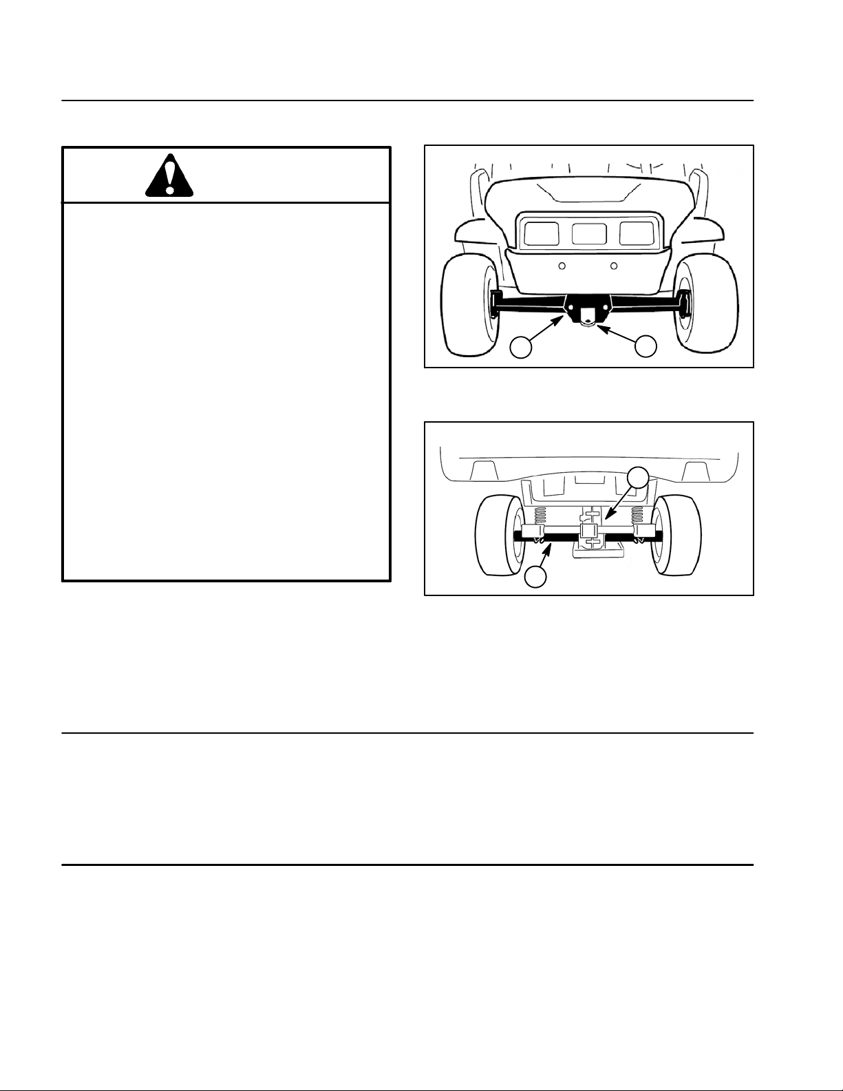
1
Figure 1
1. Front frame 2. Towing tongue
2
2
1
Jacking Locations
1. Jack front of the vehicle on the front of the frame and
behind the towing tongue (Fig. 1).
2. Jack rear of the vehicle under each rear axle tube. Do
not jack vehicle below the transaxle case (Fig. 2).
Transport Vehicle
When moving the vehicle long distances, use a trailer or
flatbed truck. Make sure vehicle is secured to the trailer
properly. Refer to Operator’s Manual for transport information.
Tow Vehicle
IMPORTANT: Frequent or long distance towing of
the Workman is not recommended.
In case of emergency, the vehicle can be towed for a
short distance. Refer to Operator’s Manual for towing
information.
Figure 2
1. Transaxle case 2. Axle tube
IMPORTANT: If vehicle is towed, make sure that
ignition switch is in the OFF position and key is removed from switch.
Workman MD/MDXPage 1 -- 4Safety
Page 9
Transaxle Neutral Position
When performing routine maintenance and/or engine
testing, the transaxle must be shifted into the neutral
position.
1. Park machine on a level surface, stop engine, set
parking brake and remove key from the ignition switch.
2
Safety
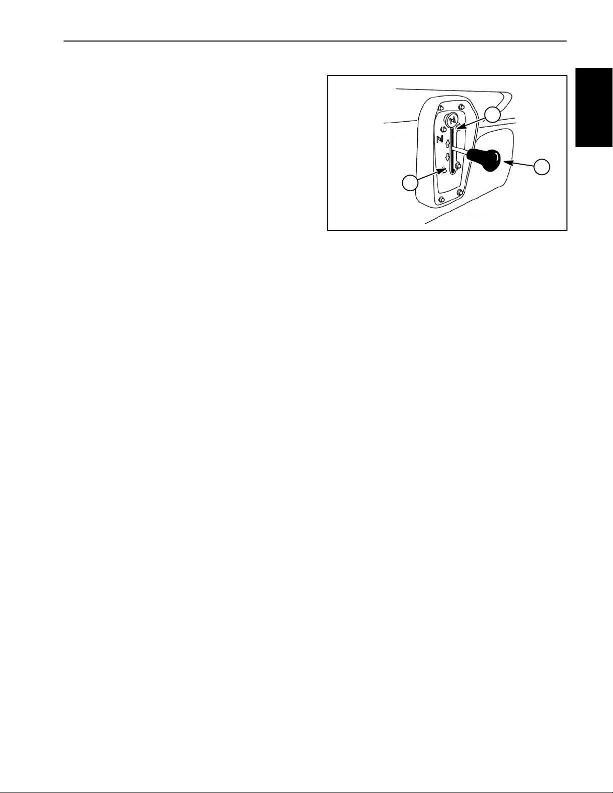
2. Move shift lever to the neutral position (Fig. 3).
3. Make sure transaxle is in the neutral position by rotating the driven clutch. The tires should not rotate. If tire
rotation does occur, see Adjust Shift Cables in the Adjustment section of Chapter 5 -- Drive Train.
3
1. Shift lever (in neutral)
2. Forward position
1
Figure 3
3. Reverse position
Workman MD/MDX Page 1 -- 5 Safety
Page 10

Safety and Instruction Decals
Numerous safety and instruction decals are affixed to
your Workman. If any decal becomes illegible or damaged, install a new decal. Part numbers are listed in the
Parts Catalog. Order replacement decals from your Authorized Toro Distributor.
Workman MD/MDXPage 1 -- 6Safety
Page 11

Product Records and Maintenance
Table of Contents
PRODUCT RECORDS 1.........................
MAINTENANCE 1...............................
EQUIVALENTS AND CONVERSIONS 2...........
Decimal and Millimeter Equivalents 2............
U.S. to Metric Conversions 2...................
TORQUE SPECIFICATIONS 3....................
Fastener Identification 3.......................
Standard Torque for Dry, Zinc Plated and
Steel Fasteners (Inch Series). 4...............
Standard Torque for Dry, Zinc Plated and
Steel Fasteners (Metric Fasteners). 5..........
Other Torque Specifications 6..................
Conversion Factors 6..........................
Product Records
Chapter 2
and Maintenance
Product Records
Insert Operator’s Manual and Parts Catalog for your
Workman at the end of this chapter. Additionally, if any
optional equipment or accessories have been installed
to your machine, insert the Installation Instructions, Operator’s Manuals and Parts Catalogs for those options
at the end of this chapter.
Maintenance
Maintenance procedures and recommended service intervals for your Workman are covered in the Operator’s
Manual. Refer to that publication when performing regular equipment maintenance.
Workman MD/MDX Page 2 -- 1 Product Records and Maintenance
Page 12
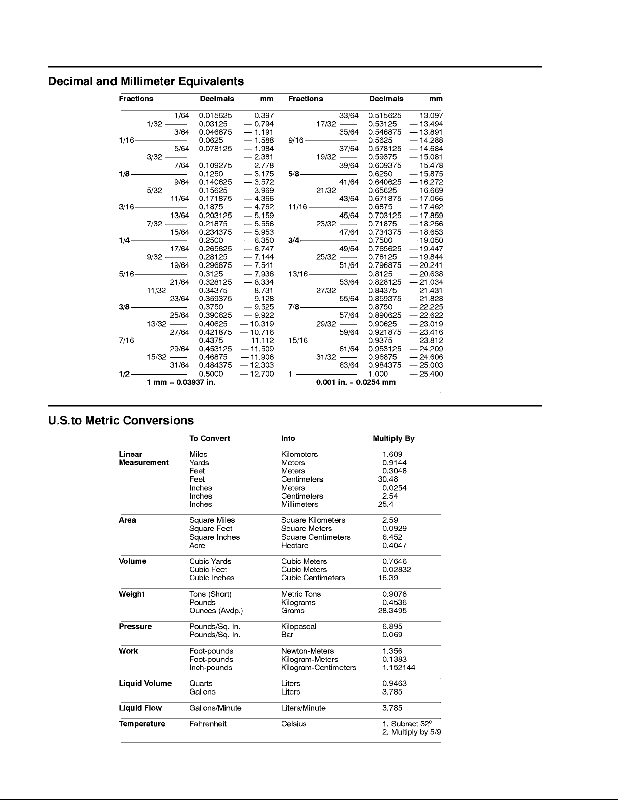
Equivalents and Conversions
0.09375
Workman MD/MDXPage 2 -- 2Product Records and Maintenance
Page 13
Torque Specifications
Recommended fastener torque values are listed in the
following tables. For critical applications, as determined
by Toro, either the recommended torque or a torque that
is unique to the application is clearly identified and specified in this Service Manual.
These Torque Specifications for the installation and
tightening of fasteners s hall apply to all fasteners which
do not have a specific requirement identified in this Service Manual. The following factors shall be considered
when applying torque: cleanliness of the fastener, use
of a thread sealant (e.g. Loctite), degree of lubrication
on the fastener, presence of a prevailing torque feature,
hardness of the surface underneath the fastener’s head
or similar condition which affects the installation.
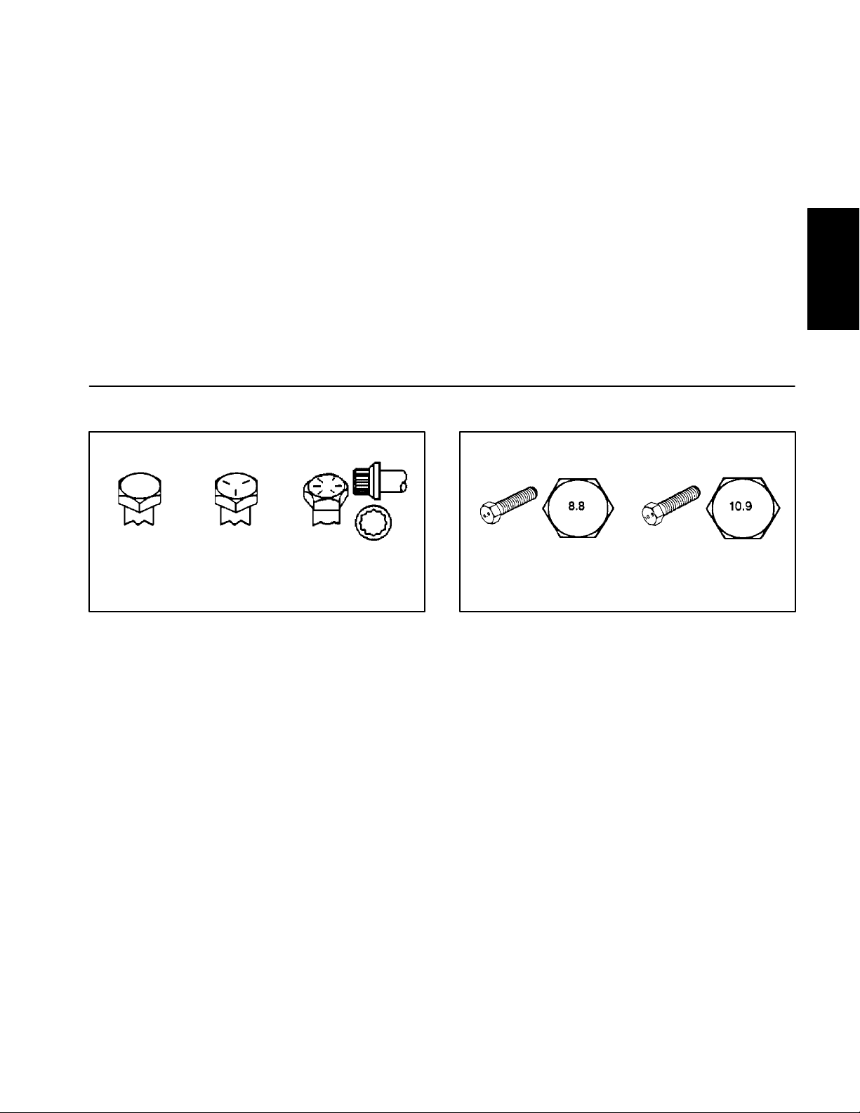
Fastener Identification
As noted in the following tables, torque values should be
reduced by 25% for lubricated fasteners to achieve
the similar stress as a dry fastener. Torque values may
also have to be reduced when the fastener is threaded
into aluminum or brass. The specific torque value
should be determined based on the aluminum or brass
material strength, fastener size, length of thread engagement, etc.
The standard method of verifying torque shall be performed by marking a line on the fastener (head or nut)
and mating part, then back off fastener 1/4 of a turn.
Measure the torque required to tighten the fastener until
the lines match up.
and Maintenance
Product Records
Grade 1 Grade 5 Grade 8
Inch Series Bolts and Screws
Figure 1
Class 8.8 Class 10.9
Metric Bolts and Screws
Figure 2
Workman MD/MDX Page 2 -- 3 Product Records and Maintenance
Page 14
Standard Torque for Dry, Zinc Plated and Steel Fasteners (Inch Series)
Thread Size
# 6 -- 32 UNC
# 6 -- 40 UNF
# 8 -- 32 UNC
# 8 -- 36 UNF
#10--24UNC
#10--32UNF
1/4 -- 20 UNC 48 + 7 53 + 7 599 + 79 100 + 10 1125 + 100 140 + 15 1580 + 170
1/4 -- 28 UNF 53 + 7 65 + 10 734 + 11 3 11 5 + 10 1300 + 100 160 + 15 1800 + 170
5/16 -- 18 UNC 115 + 15 105 + 17 1186 + 169 200 + 25 2250 + 280 300 + 30 3390 + 340
5/16 -- 24 UNF 138 + 17 128 + 17 1446 + 192 225 + 25 2540 + 280 325 + 30 3670 + 340
3/8 -- 16 UNC 16 + 2 16 + 2 22 + 3 30 + 3 41 + 4 43 + 4 58 + 5
Grade 1, 5 &
8withThin
Height Nuts
in--lb in--lb N--cm in-- lb N--cm in-- lb N--cm
10 + 2 13 + 2 147 + 23
13 + 2 25 + 5 282 + 30
18 + 2 30 + 5 339 + 56
ft--lb ft--lb N--m ft--lb N--m ft--lb N--m
SAE Grade 1 Bolts, Screws, Studs &
Sems with Regular Height Nuts
(SAE J995 Grade 2 or Stronger Nuts)
SAE Grade 5 Bolts, Screws, Studs &
Sems with Regular Height Nuts
(SAE J995 Grade 2 or Stronger Nuts)
15 + 2 170 + 20 23 + 2 260 + 20
17 + 2 190 + 20 25 + 2 280 + 20
29 + 3 330 + 30 41 + 4 460 + 45
31 + 3 350 + 30 43 + 4 485 + 45
42 + 4 475 + 45 60 + 6 675 + 70
48 + 4 540 + 45 68 + 6 765 + 70
SAE Grade 8 Bolts, Screws, Studs &
Sems with Regular Height Nuts
(SAE J995 Grade 5 or Stronger Nuts)
3/8 -- 24 UNF 17 + 2 18 + 2 24 + 3 35 + 3 47 + 4 50 + 4 68 + 5
7/16 -- 14 UNC 27 + 3 27 + 3 37 + 4 50 + 5 68 + 7 70 + 7 95 + 9
7/16 -- 20 UNF 29 + 3 29 + 3 39 + 4 55 + 5 75 + 7 77 + 7 104 + 9
1/2 -- 13 UNC 30 + 3 48 + 7 65 + 9 75 + 8 102 + 11 105 + 10 142 + 14
1/2 -- 20 UNF 32 + 3 53 + 7 72 + 9 85 + 8 11 5 + 11 120 + 10 163 + 14
5/8 -- 11 UNC 65 + 10 88 + 12 119 + 16 150 + 15 203 + 20 210 + 20 285 + 27
5/8 -- 18 UNF 75 + 10 95 + 15 129 + 20 170 + 15 230 + 20 240 + 20 325 + 27
3/4 -- 10 UNC 93 + 12 140 + 20 190 + 27 265 + 25 359 + 34 375 + 35 508 + 47
3/4 -- 16 UNF 115 + 15 165 + 25 224 + 34 300 + 25 407 + 34 420 + 35 569 + 47
7/8 -- 9 UNC 140 + 20 225 + 25 305 + 34 430 + 45 583 + 61 600 + 60 813 + 81
7/8 -- 14 UNF 155 + 25 260 + 30 353 + 41 475 + 45 644 + 61 660 + 60 895 + 81
NOTE: Reduce torque values listed in the table above
by 25% for lubricated fasteners. Lubricated fasteners
are defined as threads coated with a lubricant such as
oil, graphite or thread sealant such as Loctite.
NOTE: The nominal torque values listed above for
Grade 5 and 8 fasteners are based on 75% of the minimum proof load specified in SAE J429. The tolerance is
approximately +
10% of the nominal torque value. Thin
height nuts include jam nuts.
NOTE: Torque values may have to be reduced when
installing fasteners into threaded aluminum or brass.
The specific torque value should be determined based
on the fastener size, the aluminum or base material
strength, length of thread engagement, etc.
Workman MD/MDXPage 2 -- 4Product Records and Maintenance
Page 15
Standard Torque for Dry, Zinc Plated and Steel Fasteners (Metric Fasteners)
Class 8.8 Bolts, Screws and Studs with
Thread Size Regular Height Nuts
(Class 8 or Stronger Nuts)
M5 X 0.8 57 + 5in--lb 640 + 60 N--cm 78 + 7in--lb 885 + 80 N--cm
M6 X 1.0 96 + 9in--lb 1018 + 100 N--cm 133 + 13 in--lb 1500 + 150 N --cm
M8 X 1.25 19 + 2ft--lb 26 + 3N--m 27 + 2ft--lb 36 + 3N--m
M10 X 1.5 38 + 4ft--lb 52 + 5N--m 53 + 5ft--lb 72 + 7N--m
M12 X 1.75 66 + 7ft--lb 90 + 10 N--m 92 + 9ft--lb 125 + 12 N--m
M16 X 2.0 166 + 15 ft--lb 225 + 20 N--m 229 + 22 ft--lb 310 + 30 N--m
M20 X 2.5 325 + 33 ft--lb 440 + 45 N--m 450 + 37 ft--lb 610 + 50 N--m
NOTE: Reduce torque values listed in the table above
by 25% for lubricated fasteners. Lubricated fasteners
are defined as threads coated with a lubricant such as
oil, graphite or thread sealant such as Loctite.
NOTE: Torque values may have to be reduced when
installing fasteners into threaded aluminum or brass.
The specific torque value should be determined based
on the fastener size, the aluminum or base material
strength, length of thread engagement, etc.
NOTE: The nominal torque values listed above are
based on 75% of the minimum proof load specified in
SAE J1199. The tolerance is approximately+
nominal torque value.
Class 10.9 Bolts, Screws and Studs with
Regular Height Nuts
(Class 10 or Stronger Nuts)
10% ofthe
and Maintenance
Product Records
Workman MD/MDX Page 2 -- 5 Product Records and Maintenance
Page 16

Other Torque Specifications
*
SAE Grade 8 Steel Set Screws
Recommended Torque
Thread Size
Square Head Hex Socket
1/4 -- 20 UNC 140 + 20 in--lb 73 + 12 in--lb
5/16 -- 18 UNC 215 + 35 in--lb 145 + 20 in--lb
3/8 -- 16 UNC 35 + 10 ft--lb 18 + 3ft--lb
1/2 -- 13 UNC 75 + 15 ft--lb 50 + 10 ft--lb
Thread Cutting Screws
(Zinc Plated Steel)
Type 1, Type 23 or Type F
Thread Size Baseline Torque*
No. 6 -- 32 UNC 20 + 5in--lb
Wheel Bolts and Lug Nuts
Thread Size
7/16 -- 20 UNF
Grade 5
1/2 -- 20 UNF
Grade 5
M12 X 1.25
Class 8.8
M12 X 1.5
Class 8.8
** For steel wheels and non--lubricated fasteners.
Thread Cutting Screws
(Zinc Plated Steel)
Thread
Size
No. 6 18 20 20 + 5in--lb
Threads per Inch
Type A Typ e B
Recommended Torque**
65 + 10 ft--lb 88 + 14 N--m
80 + 10 ft--lb 108 + 14 N--m
80 + 10 ft--lb 108 + 14 N--m
80 + 10 ft--lb 108 + 14 N--m
Baseline Torque
No. 8 -- 32 UNC 30 + 5in--lb
No. 10 -- 24 UNC 38 + 7in--lb
1/4 -- 20 UNC 85 + 15 in--lb
5/16 -- 18 UNC 110 + 20 in--lb
3/8 -- 16 UNC 200 + 100 in--lb
Conversion Factors
in--lb X 11.2985 = N--cm N--cm X 0.08851 = in--lb
ft--lb X 1.3558 = N--m N--m X 0.7376 = ft--lb
No. 8 15 18 30 + 5in--lb
No. 10 12 16 38 + 7in--lb
No. 12 11 14 85 + 15 in--lb
* Holesize, material strength, material thickness and finish must be considered when determining specific
torque values. All torque values are based on non--lubricated fasteners.
Workman MD/MDXPage 2 -- 6Product Records and Maintenance
Page 17

Briggs & Stratton Gasoline Engine
Table of Contents
GENERAL INFORMATION 2.....................
Operator’s Manual 2..........................
SPECIFICATIONS 3.............................
ADJUSTMENTS 4..............................
Adjust Throttle Cable 4........................
SERVICE AND REPAIRS 5......................
Cooling System 5.............................
Air Cleaner 6.................................
Exhaust System 8............................
Fuel Tank 10.................................
Oil Filter Assembly 12.........................
Engine 14....................................
Engine Removal 15..........................
Engine Installation 16........................
BRIGGS & STRATTON REPAIR MANUAL FOR
4--CYCLE, V--TWIN CYLINDER, OHV HEAD ENGINES
Chapter 3
Gasoline Engine
Briggs & Stratton
Workman MDX Page 3 -- 1 Briggs & Stratton Gasoline Engine
Page 18

General Information
This Chapter gives information about specifications,
maintenance, troubleshooting, testing and repair of the
V--twin cylinder, gasoline engine used in the Workman
MDX.
Most repairs and adjustments require tools w hich are
commonly available in many service shops. Special
tools are described in the Briggs & Stratton Repair
Manual for 4--Cycle, V--Twin Cylinder, OHV Head En-
Operator’s Manual
The Operator’s Manual provides information regarding
the operation, general maintenance and maintenance
intervals for your Workman MDX vehicle. Refer to the
Operator’s Manual for additional information when servicing the machine.
gines. The use ofsome specialized test equipment isexplained. However, the cost of the test equipment and the
specialized nature of some repairs may dictate that the
work be done at an engine repair facility.
Service and repair parts for Briggs & Stratton engines
are supplied through your local Toro distributor. If no
parts list is available, be sure to provide your distributor
with the Toro model and serial number.
Workman MDXPage 3 -- 2Briggs & Stratton Gasoline Engine
Page 19

Specifications
Item Description
Make / Designation Briggs and Stratton, 4--cycle, V--Twin Cylinder,
OHV, Air Cooled, Gasoline Engine -- Model 303440
Bore x Stroke 2.68” x 2.60” (68 mm x 66 mm)
Total Displacement 29.3 in3(480 cc)
Governor Mechanical Governor
Carburetor Float Feed, Single Barrel
Fuel Pump Pulsating Crankcase Vacuum
Fuel Unleaded, regular grade gasoline
Fuel Tank Capacity 7.0 U.S. gal (26.5 l)
Lubrication System Pressure Lubrication, Gear Driven Geroter Oil Pump
Crankcase Oil Capacity 1.75 U.S. qt (1.66 l) with new filter
Engine Oil See Operator’s Manual
Ignition System Flywheel magneto, twin electronic armatures
Spark Plugs Champion RC 12YC (or equivalent)
Gasoline Engine
Briggs & Stratton
Spark Plug Gap 0.030” (0.76 mm)
Starter/Generator 10.5 VDC 100 Amps/14 VDC and 23 Amps
Dry Weight (approximate) 72 lb (32.4 kg)
Workman MDX Page 3 -- 3 Briggs & Stratton Gasoline Engine
Page 20
Adjustments
Adjust Throttle Cable
NOTE: The Workman MDX is equipped with an engine
governor. Refer to the Briggs & Stratton Repair Manual
at the end of this chapter for governor information on
these machines.
Depressing the accelerator pedal rotates the engine
governor bellcrank which tensions the main governor
spring to increase engine speed. Releasing the accelerator pedal decreases governor spring tension to reduce
engine speed.
1. Park machine on a level surface, stop engine, engage parking brake and remove key from the ignition
switch.
2. Lift cargo box and prop with rod to gain access to the
engine.
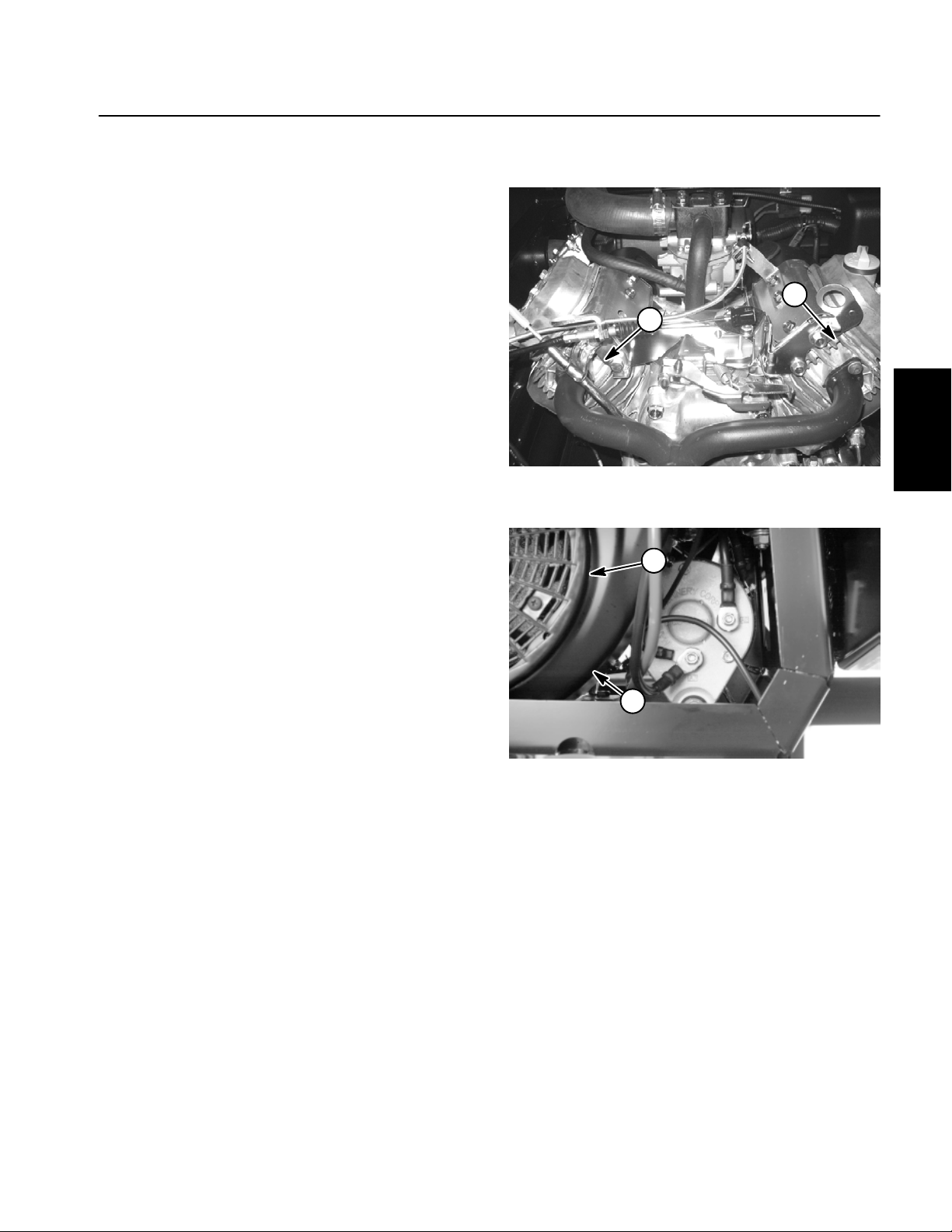
3. When the accelerator pedal is fully depressed the
engine governor bellcrank mechanism should have a
gap from 0.030” to 0.080” (0.8 to 2.0 mm) (Fig. 2). If necessary, adjust jam nuts on accelerator cable so that gap
is correct.
2
ACCELERATOR
PEDAL RELEASED
1
Figure 1
1. Throttle cable 2. Governor bellcrank
2
4. After throttle cable adjustment is correct, lower and
secure cargo box.
ACCELERATOR
PEDAL DEPRESSED
1. Throttle cable
2. Governor bellcrank
3
1
Figure 2
3. Gap
Workman MDXPage 3 -- 4Briggs & Stratton Gasoline Engine
Page 21
Service and Repairs
Cooling System
To ensure proper engine cooling, make sure the grass
screen, cooling fins and other external surfaces of the
engine are kept clean at all times.
NOTE: Perform this maintenance procedure at the interval specified in the Operator’s Manual.
IMPORTANT: The engine that powers the Workman
MDX is air--cooled. Operating the engine with dirty
or plugged cooling fins or a plugged or dirty blower
housing w ill result in engine overheating and damage.
1. Park machine on a level surface, stop engine, engage parking brake and remove key from the ignition
switch.
2. Raise cargo box and support with prop rod.
3. Carefully remove spark plug wires from the spark
plugs to prevent the engine from starting unexpectedly.
IMPORTANT: Never clean engine with pressurized
water. Water could enter and contaminate the fuel
system.
4. Clean cooling fins on both cylinder heads (Fig. 3).
5. Clean rotating screen and blower housing of dirt and
debris.
6. If necessary remove rotating screen and blower
housing fromengine for more thorough engine cleaning.
2
1
1
Figure 3
1
Gasoline Engine
Briggs & Stratton
IMPORTANT: Never operate engine without the rotating screen and blower housing installed. Overheating and engine damage will result.
7. Make sure rotating screen and blower housing are
properly installed to the engine if removed.
8. Attach spark plug wires to spark plugs.
9. Lower and secure cargo box.
Workman MDX Page 3 -- 5 Briggs & Stratton Gasoline Engine
1. Rotating screen 2. Blower housing
Figure 4
Page 22
Air Cleaner
18
17
5
4
6
3
2
8
7
9
60 to 65 in-- lb
(6.8 to 7.3 N-- m)
10
1
11
12
19
13
12
14
15
16
17
RIGHT
FRONT
1. Air cleaner assembly
2. Bolt
3. Compression spring
4. Mounting band
5. Nut
6. Flange nut (2 used)
Figure 5
7. Cap screw (2 used)
8. Air cleaner bracket
9. Flange head screw (4 used)
10. Carburetor gasket (2 used)
11. Carburetor adapter
12. Hose clamp
13. Breather hose
14. Adapter gasket
15. Hose clamp
16. Intake hose
17. Hose clamp
18. Intake hose
Workman MDXPage 3 -- 6Briggs & Stratton Gasoline Engine
Page 23
Removal (Fig. 5)
1. Make sure machine is parked on a level surface with
the engine OFF.
2. Raise cargo box and support with prop rod.
3. Thoroughly clean junction of intake hose and carburetor adapter on engine and air cleaner assembly.
4. Remove air cleaner components as needed using
Figure 5 as a guide. Discard any removed gaskets and
clean gasket mating surfaces.
Installation (Fig. 5)
IMPORTANT: Any leaks in the air filter system will
allow dirt into engine and will cause serious engine
damage. Make sure that all air cleaner components
are in good condition and are properly secured during assembly.
1. Assemble all removed air cleaner components using
Figure 5 as a guide.
A. Install new gaskets (items 10 and 14) if they were
removed.
1
1. Air cleaner
2. Carburetor adapter
Figure 6
3. Breather hose
4. Intake hose
2
3
4
Gasoline Engine
Briggs & Stratton
B. If flange head screws ( item 9) were loosened or
removed, torque screws from 60 to 65 in--lb (6.8 to
7.3 N--m).
C. Make sure that air cleaner vacuator valve is
pointed toward ground and slightly toward engine after assembly.
D. Make sure to secure intake hoses with hose
clamps.
2. Lower and secure cargo box.
Workman MDX Page 3 -- 7 Briggs & Stratton Gasoline Engine
Page 24
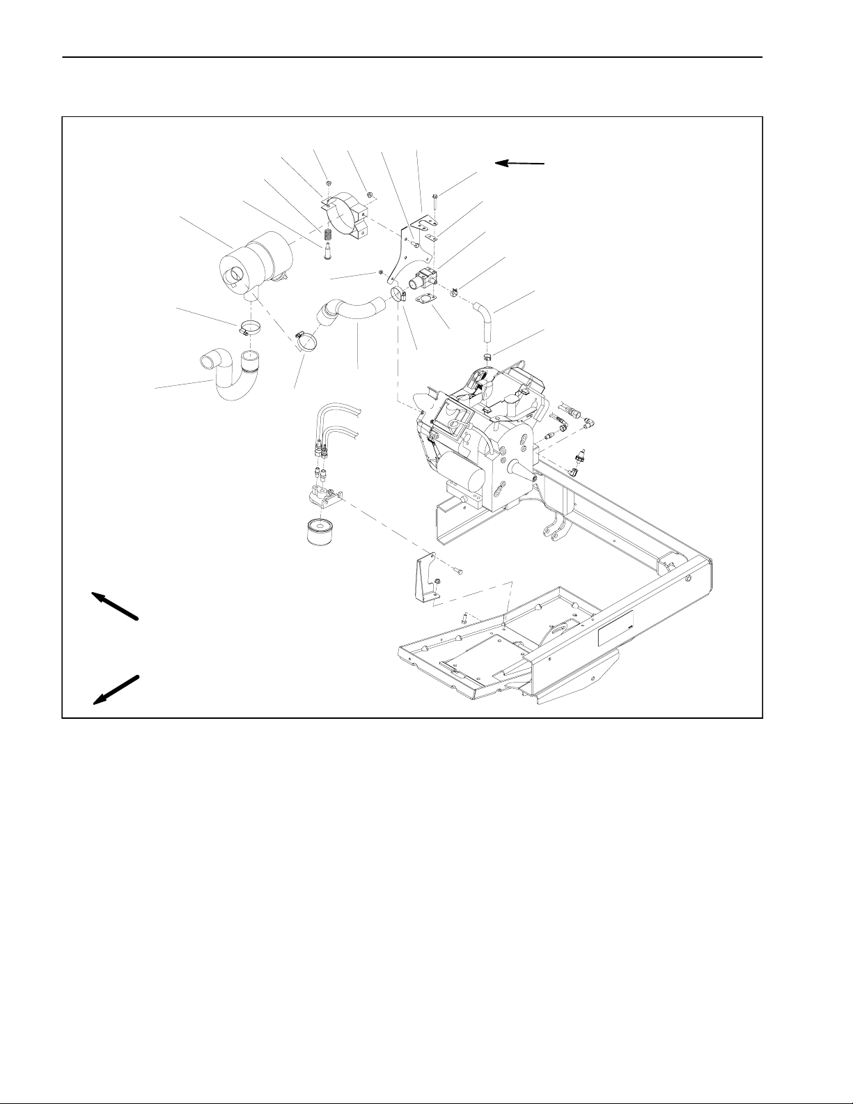
Exhaust System
RIGHT
FRONT
8
9
4
10
1
2
7
6
5
4
3
1. Muffler
2. Swing arm
3. Cap screw (2 used)
4. Lock washer (6 used)
Figure 7
5. Exhaust coupler
6. Coupler spring (4 used)
7. Exhaust manifold
8. Engine tray
9. Engine
10. Screw (4 used)
Workman MDXPage 3 -- 8Briggs & Stratton Gasoline Engine
Page 25

Removal (Fig. 7)
Installation (Fig. 7)
1. Park machine on a level surface, stop theengine, engage parkingbrake and remove the key from the ignition
switch.
2. Raise cargo box and support with prop rod.
CAUTION
The muffler and exhaust pipe may be hot. To
avoid possible burns, allow engine and exhaust
system to cool before working on the muffler.
3. Remove four (4) coupler springs securing the exhaust coupler to the muffler and exhaust manifold. Remove exhaust coupler.
4. Remove two (2) cap screws and lock washers securing the muffler to the swing arm. Remove muffler from
machine.
5. If exhaust manifold needs to be removed from engine, remove four (4) screws and lock washers securing
the manifold to the engine. Remove exhaust manifold.
Remove exhaust gaskets and clean gasket surfaces of
manifold and engine.
NOTE: Mount all exhaust components loosely before
tightening to ensure a proper fit of exhaust system.
1. If the exhaust manifold was removed from engine,
install manifold to engine with new gaskets. Make sure
that gaskets align with exhaust ports of cylinder heads.
Loosely attach exhaust manifold to the engine with removed fasteners.
2. Position muffler to the machine. Secure muffler
loosely to the swing arm with two (2) cap screws and
lock washers.
3. Position exhaust coupler to the muffler and exhaust
manifold. Secure coupler with four (4) coupler springs.
4. Tighten screws that secure exhaust manifold to the
engine.
5. Tighten cap screws that secure muffler to the swing
arm.
6. Lower and secure cargo box.
Gasoline Engine
Briggs & Stratton
Workman MDX Page 3 -- 9 Briggs & Stratton Gasoline Engine
Page 26
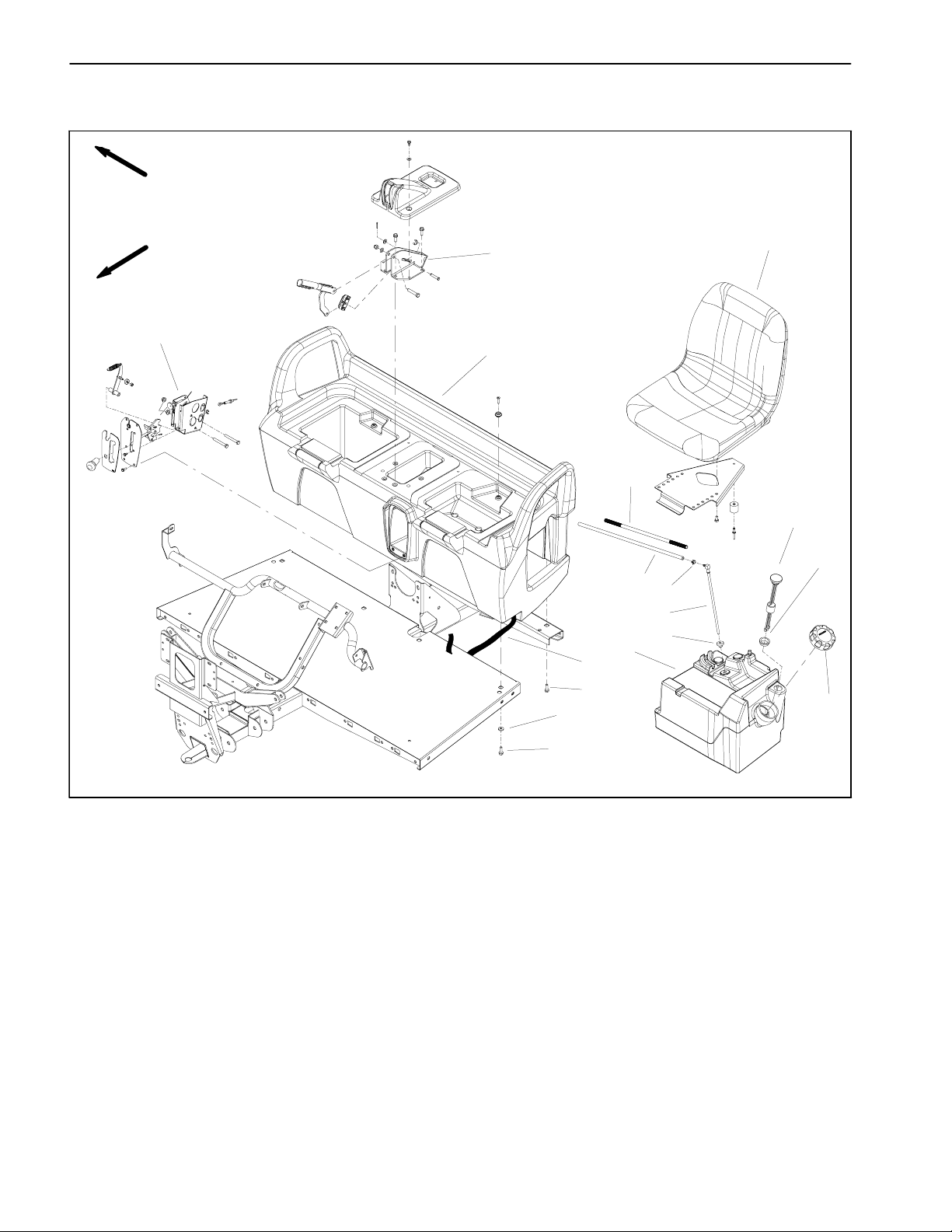
Fuel Tank
RIGHT
FRONT
16
11
15
14
12
13
10
5
1
2
3
9
8
7
6
4
1. Seat
2. Fuel gauge
3. Bushing
4. Gas cap
5. Fuel tank
6. Bushing
7. Stand pipe
Figure 8
8. Hose clamp
9. Fuel hose (to fuel filter)
10. Fuel line conduit
11. Seat base
13
12. Web strapping
13. Hex head flange screw (8 used)
14. Flat washer
15. Parking brake support
16. Shift bracket
Workman MDXPage 3 -- 10Briggs & Stratton Gasoline Engine
Page 27
Fuel Tank Removal (Fig. 10)
CAUTION
Read safety precautions for handling gasoline
before working on the fuel system (see Safety Instructions in Chapter 1 -- Safety).
4
2
5
1. Remove seat base from the frame (see Seat Base
Removal in the Service and Repairs section of Chapter
7 -- Chassis).
2. Use fuel transfer pump to remove gas from fuel tank.
3. Loosen hose clamp and disconnect fuel hose from
the fuel tank stand pipe.
4. Release tank strap that secures fuel tank to frame.
Do not remove strap from floor plate and frame cross
member. Lift tank from frame.
5. If necessary, remove stand pipe, fuel gauge and
bushings from tank.
Fuel Tank Installation (Fig. 10)
1. If removed, install bushings, stand pipe and fuel
gauge to tank.
2. Position fuel tank to frame. Secure tank to frame and
cross member with tank strap.
3. Connect fuel hose to the tank stand pipe and secure
with hose clamp.
4. Install seat base to the frame (see Seat Base Installation in the Service and Repairs section of Chapter 7 -Chassis).
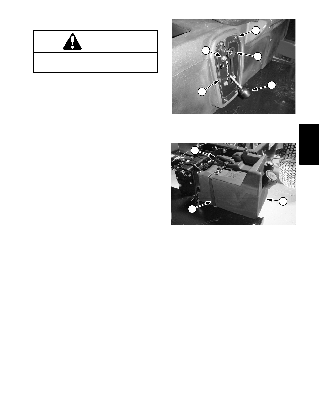
3
1. Shift lever
2. Cap screw (short)
3. Shift plate
1
3
1. Fuel hose
2. Fuel tank
Figure 9
4. Cap screw (long)
5. Choke cable
Figure 10
3. Tank strap
1
Gasoline Engine
Briggs & Stratton
2
5. Fill fuel tank.
Workman MDX Page 3 -- 11 Briggs & Stratton Gasoline Engine
Page 28
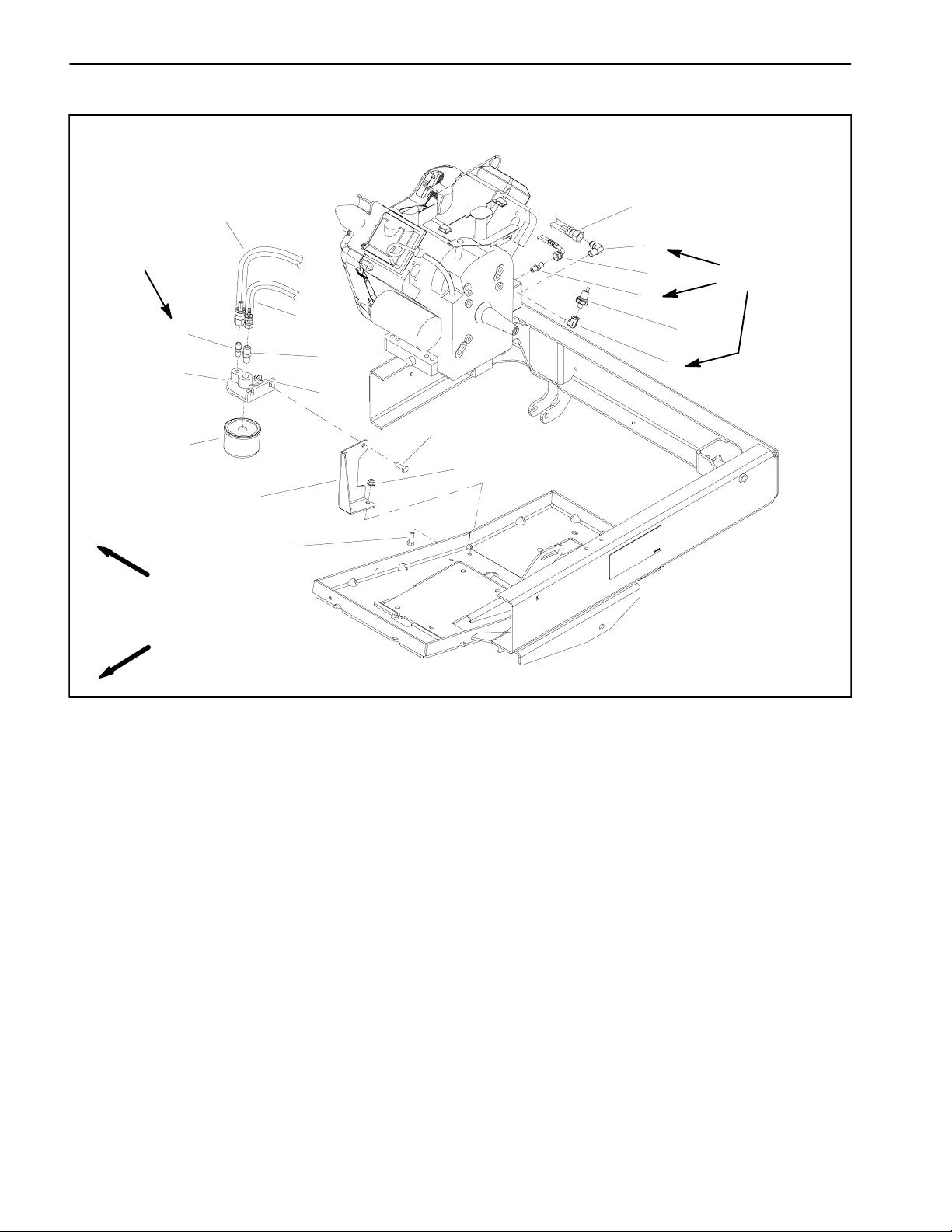
Oil Filter Assembly
40 to 50 in-- lb
(4.6 to 5.6 N-- m)
11
RIGHT
FRONT
4
10
1
1
2
3
40 to 50 in-- lb
(4.6 to 5.6 N-- m)
4
3
12
5
6
8
7
8
9
7
1. Hose
2. Elbow fitting
3. Hose
4. Fitting
Figure 11
5. Oil pressure switch
6. Elbow fitting
7. Cap screw (4 used)
8. Flange nut (4 used)
9. Filter bracket
10. Oil filter
11. Oil filter adapter
12. Fitting
Workman MDXPage 3 -- 12Briggs & Stratton Gasoline Engine
Page 29

Removal (Fig. 11)
Installation (Fig. 11)
1. Park machine on a level surface, stop theengine, engage parkingbrake and remove the key from the ignition
switch.
2. Raise cargo box and support with prop rod.
3. To prevent contamination of engine lubrication system duringadapter removal, thoroughly clean exteriorof
filter adapter, hoses and fittings.
4. Remove oil filter adapter components as needed using Figure 11 as a guide.
1. Install removed oil filter adapter components using
Figure 11 as a guide. Torque fittings (items 2, 4 and 6)
from 40 to 50 in--lb (4.6 to 5.6 N--m).
2. Check and adjust engine oil level.
3. Lower and secure cargo box.
Gasoline Engine
Briggs & Stratton
Workman MDX Page 3 -- 13 Briggs & Stratton Gasoline Engine
Page 30
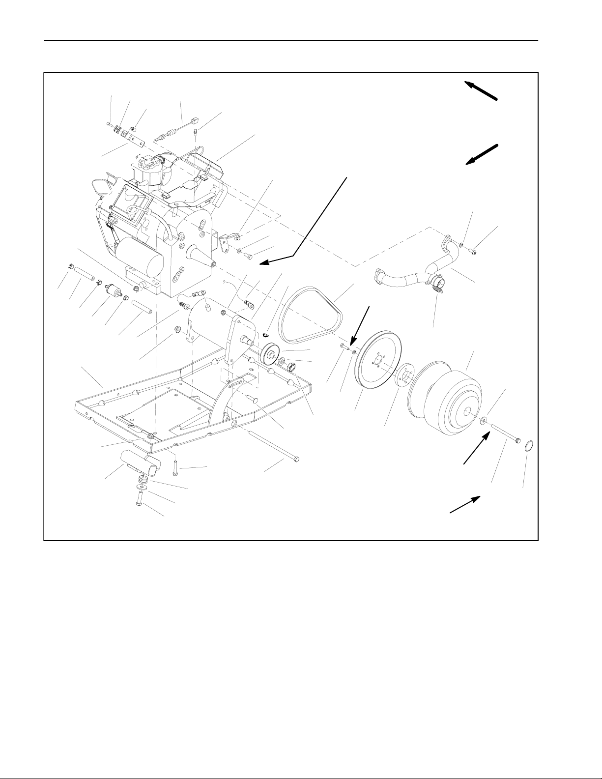
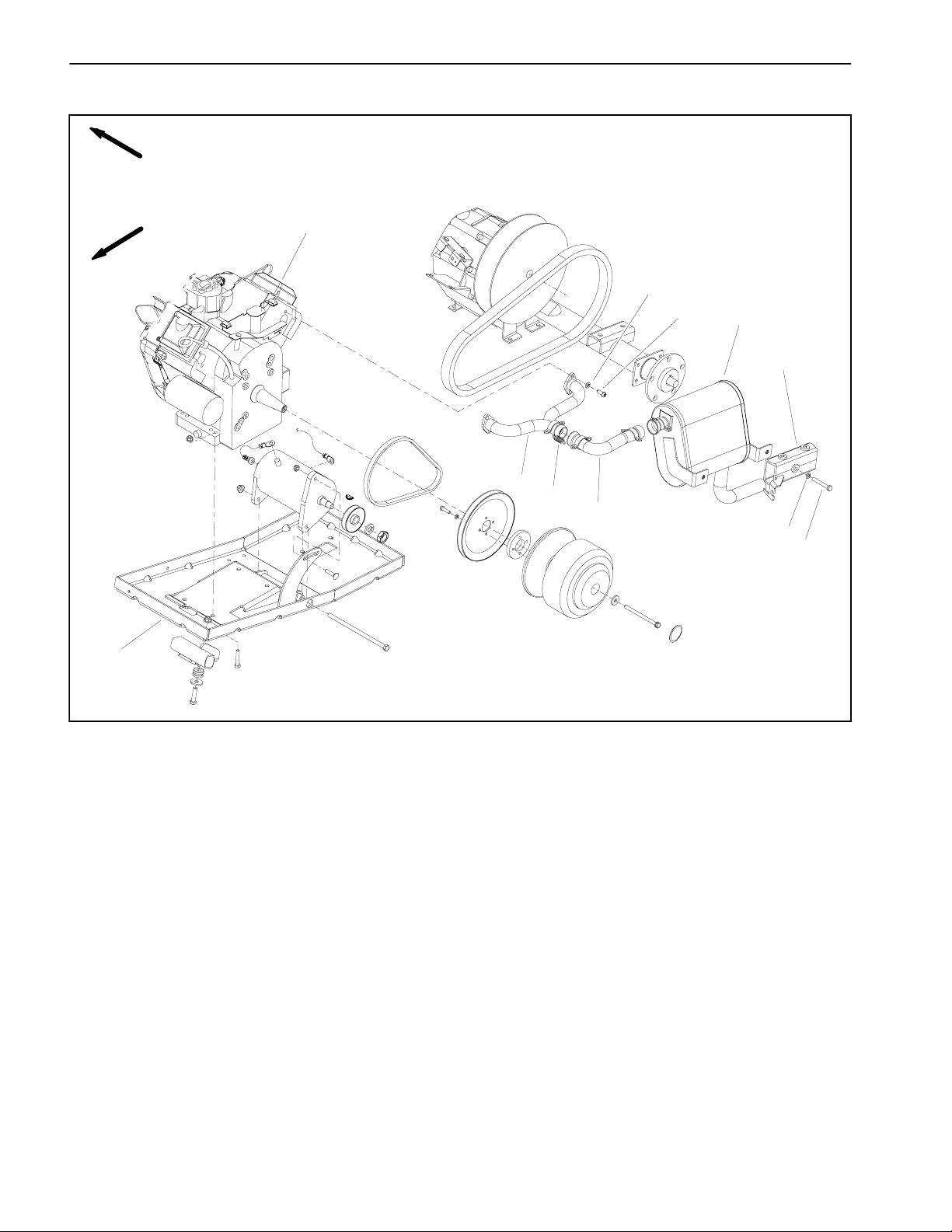
Engine
5
4
3
41
6
40
30
39
RIGHT
FRONT
65 to 85 ft-- lb
(88 to 115 N--m)
8
33
8
31
9
28
10
13
42
Loctite #242
22
38
1
37
1
36
25
1
2
17
29
27
11
43
19
20
14
15
29
7
1. Hose clamp
2. Fuel hose (from tank)
3. Cable bracket
4. Cable clamp
5. Cap screw
6. Threaded insert
7. Swing arm
8. Lock washer (6 used)
9. Cap screw (2 used)
10. Woodruff key
11. Lock washer
12. Nut
13. Starter V-- belt
14. Cap screw (4 used)
15. Lock washer (4 used)
32
26
35
23
34
16. Engine pulley
17. Negative cable
18. Starter spacer
19. Drive clutch
20. Washer
21. Cap screw
22. Flange nut (4 used)
23. Cap screw
24. Carriage screw
25. Engine tray
26. Washer (2 used)
27. Starter/generator pulley
28. Starter/generator
29. Flange nut (3 used)
30. Engine
24
Figure 12
12
16
18
Loctite #242
25 to 30 ft-- lb
(34to40N--m)
31. Engine wire harness
32. Cap screw (2 used)
33. Screw (4 used)
34. Mount (2 used)
35. Cap screw (4 used)
36. Fuel filter
37. Fuel hose
38. Lock nut
39. Cable bracket
40. Ball stud
41. Cable
42. Exhaust manifold
43. Coupler spring (4 used)
44. Plastic cap
21
44
Workman MDXPage 3 -- 14Briggs & Stratton Gasoline Engine
Page 31

Engine Removal (Fig. 12)
1. Park machine on a level surface, stop engine, engage parking brake and remove key from the ignition
switch.
2. Disconnect negative (black) cable from the battery.
Then, disconnect positive (red) cable from the battery.
3. Remove cargo box to gain access to the engine (see
Cargo Box and Tailgate Removal in the Service and Repairs section of Chapter 7 -- Chassis).
3
4
2
4. Depending on needed engine repairs,it may be easier to drain engine oil from engine before engine removal.
IMPORTANT: To prevent contaminants from entering the engine and fuel system, make sure all hoses
and engine openings are covered or plugged after
disconnecting.
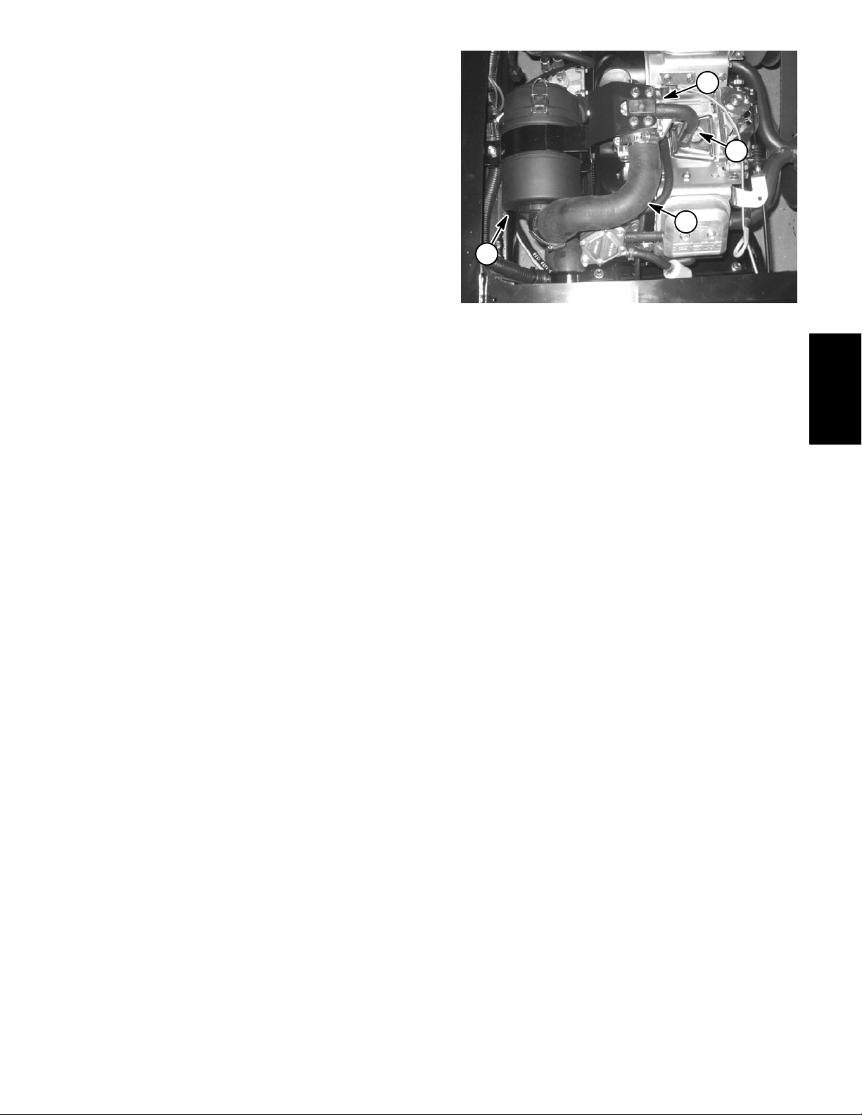
5. Disconnect the following components (Fig. 13):
A. Choke and throttle cables from the c arburetor
and cable brackets.
B. Air intake hose from the air cleaner intake and
machine frame.
CAUTION
Read safety precautions for handling gasoline
before working on the fuel system (see Safety Instructions in Chapter 1 -- Safety).
6. Disconnect fuel inlet hose from the fuel pump (Fig.
13).
7. Remove muffler and exhaust coupler from the machine (see Exhaust System Removal in this section).
1. Throttle cable
2. Choke cable
3. Cable bracket
5
4
2
1. Choke cable
2. Throttle cable
3. Carburetor
5
Figure 13
4. Air intake hose
5. Fuel inlet hose
Figure 14
4. Fuel hose
5. Air intake hose
6. Breather hose
1
6
Gasoline Engine
Briggs & Stratton
3
1
8. Remove drive belt from drive clutch.
9. Loosen fasteners that secure starter/generator. Rotate starter/generator to loosen tension on starter belt
and remove belt from the engine and starter/generator
pulleys.
10.Remove two (2) cap screws and flange nuts that secure oil filter adapter to filter bracket (Fig. 16). Carefully
2
place filter and adapter to allow them to be removed with
engine.
1
Figure 15
1. Starter/Generator ground cable to engine
2. Starter/Generator terminal (A1)
Workman MDX Page 3 -- 15 Briggs & Stratton Gasoline Engine
Page 32

11. Disconnect electrical connections from the following
engine components:
A. Disconnect ground cable to engine at starter/
generator terminal A1 (Fig. 15).
6
B. Disconnect engine harness connector from the
main harness.
12.Remove four (4) flange nuts and cap screws securing the engine to the engine tray.
CAUTION
One person should operate the hoist while the
other person guides the engine out of the frame.
13.Remove engine from the engine tray.
A. Attach a short section of chain between both engine lift tabs.
B. Connect hoist to center of chain.
IMPORTANT: Make sure to not damage the engine, fuel hoses, electrical harness or other parts
while removing the engine.
C. Slowly remove engine from the machine.
5
1
2
3
4
Figure 16
1. Oil filter adapter
2. Oil filter
3. Filter bracket
4. Cap screw
5. Flange nut
6. Engine
3. Install four (4) cap screws and flange nuts to engine
and engine tray. Position engine on engine tray to align
clutch drive pulley and driven pulley on transaxle. Tighten fasteners.
4. Carefully position oil filter assembly to filter bracket
(Fig. 16). Secure filter adapter with two (2) cap screws
and flange nuts.
14.Remove engine parts and attachments as necessary to repair the engine.
Engine Installation (Fig. 12)
1. Install all removed parts and attachments to the engine.
CAUTION
One person should operate the hoist while the
other person guides the engine into the frame.
2. Install engine to the engine tray.
A. Attach a short section of chain between both engine lift tabs.
B. Connect a hoist at the center of the short section
of chain.
IMPORTANT: Make sure to not damage engine,
fuel lines, electrical harness or other parts while
installing the engine.
5. Connect the following electrical components:
A. Connect ground cable from the engine at starter/
generator terminal A1 (Fig. 15).
B. Connect engine harness connector to the main
harness connector.
6. Install starter belt to the engine and starter/generator
pulleys. Tension the belt by rotating the starter/generator away from the engine. Tighten fasteners to secure
starter/generator.
7. Install drive belt to drive clutch.
IMPORTANT: Make sure to remove all plugs and
covers that were placed on hose and engine openings during engine removal.
8. Install muffler and exhaust coupler to the machine
(see Exhaust System Installation in this section).
9. Connect fuel inlet hose to the fuel pump (Fig. 13).
C. Carefully lower engine onto the engine tray.
Workman MDXPage 3 -- 16Briggs & Stratton Gasoline Engine
Page 33

10.Connect the following components (Fig. 13):
A. Choke and throttle cables to the carburetor and
cable bracket.
B. Air intake hose to the air cleaner intake and machine frame.
11. Install cargo box to the frame (see Cargo Box and
Tailgate Installation in the Service and Repairs section
of Chapter 7 -- Chassis).
12.Connect positive (red) cable to the battery. Then,
connect negative (black) cable to the battery.
13.Make sure engine oil level is correct.
Gasoline Engine
Briggs & Stratton
Workman MDX Page 3 -- 17 Briggs & Stratton Gasoline Engine
Page 34

This page is intentionally blank.
Workman MDXPage 3 -- 18Briggs & Stratton Gasoline Engine
Page 35

Single Cylinder Gasoline Engine
Table of Contents
GENERAL INFORMATION 2.....................
Operator’s Manual 2..........................
SPECIFICATIONS 3.............................
ADJUSTMENTS 4..............................
Adjust Throttle Cable 4........................
SERVICE AND REPAIRS 5......................
Cooling System 5.............................
Exhaust System 6............................
Fuel Tank 8..................................
Engine 10....................................
Engine Removal 11..........................
Engine Installation 12........................
KOHLER SERVICE MANUAL FOR COMMAND PRO
CS SERIES ENGINES
Chapter 4
Single Cylinder
Gasoline Engine
Workman MD Single Cylinder Gasoline EnginePage 4 -- 1
Rev. A
Page 36

General Information
This Chapter gives information about specifications,
maintenance, troubleshooting, testing and repair of the
single cylinder gasoline engine used in the Workman
MD.
Workman MD vehicles with serial numbers below
311000000 have an engine that is identified as a Kohler
Command Pro CS engine. Workman MD vehicles with
serial numbers above 311000000 have an engine that
is identified as a YamahaMZ360 engine. From a service
standpoint, these engines are essentially the same. The
Kohler Service Manual for COMMAND PRO CS Series
Engines is included at the end of this chapter and can be
used when servicing either brand of engine.
Operator’s Manual
The Operator’s Manual provides information regarding
the operation, general maintenance and maintenance
intervals for your Workman MD vehicle. Refer to the Operator’s Manual for additional information when servicing the machine.
Most repairs and adjustments require tools which are
commonly available in many service shops. Special
tools are described in the Kohler Service Manual for
COMMAND PRO C S Series Engines and the use of
some specialized test equipment is explained. The cost
of the test equipment and the specialized nature of
some repairs may dictate that engine work be done at
an engine repair facility.
Service and repair parts for theengine used in the Workman MD can be provided by your local Toro distributor.
Rev. A
Workman MDPage 4 -- 2Single Cylinder Gasoline Engine
Page 37

Specifications
Item Description
Make / Designation 4--cycle, Single Cylinder, OHV,
Air Cooled, Gasoline Engine
Bore x Stroke 3.35 in x 2.48 in (85 mm x 63 mm)
Total Displacement 21.8 in3(357 cc)
Governor Transaxle, Ground Speed Governing
Carburetor Float Feed, Single Barrel
Fuel Pump Pulsating Crankcase Vacuum
Fuel Unleaded regular grade gasoline
Fuel Tank Capacity 7.0 U.S. gal (26.5 l)
Lubrication System Splash Lubrication
Crankcase Oil Capacity 1.2U.S.qt(1.1l)
Engine Oil See Operator’s Manual
Spark Plugs Champion RC 14YC (or equivalent)
Spark Plug Gap 0.030 in (0.76 mm)
Single Cylinder
Gasoline Engine
Starter/Generator 10.5 VDC 100 Amps/14 VDC and 23 Amps
Dry Weight (approximate) 70.5 lb (31.9 kg)
Workman MD Single Cylinder Gasoline EnginePage 4 -- 3
Rev. A
Page 38

Adjustments
Adjust Throttle Cable
Releasing theaccelerator pedal should allow thethrottle
cable to close the carburetor throttle control lever so that
the lever touches the adjustment screw. The adjustment
screw keeps the throttle valve inside the carburetor
open slightly to prevent the valve from binding.
1. Park machine on a level surface, stop engine, engage parking brake and remove key from the ignition
switch.
2. Lift cargo box and prop with rod to gain access to the
engine and transaxle.
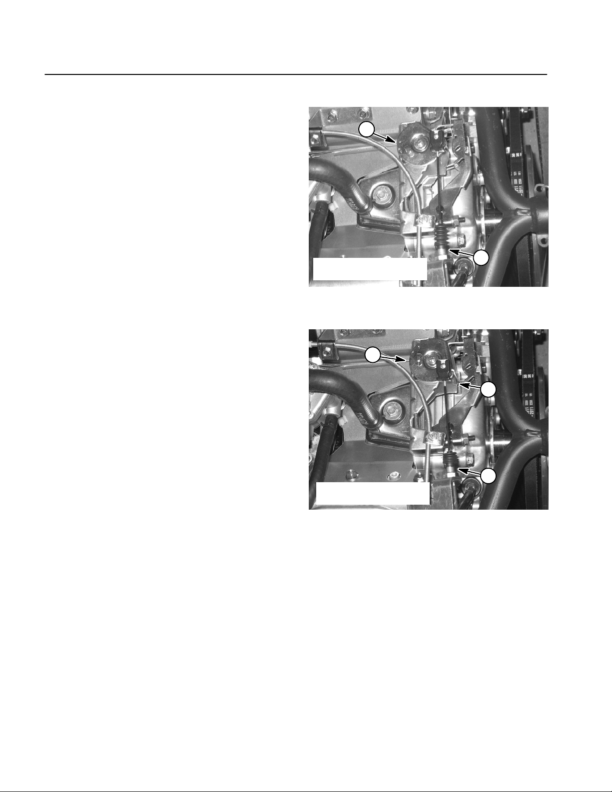
3. Rotate governor arm on transaxle fully clockwise
(Fig. 1).
4. Make sure of the following:
A. The carburetor throttle lever should be to the fully
open position without contacting the stop (Fig. 2).
B. Adjust governor cable at the transaxle cable
bracket as necessary, so there is no compression of
the cable (Fig. 1). This will allow the throttle lever to
fully close when the accelerator pedal is released.
1
3
1. Governor arm
2. Throttle cable
4
2
Figure 1
3. Governor cable
4. Cable bracket
5. Release the governor arm on transaxle and make
sure that the carburetor throttle lever fully closes.
6. After throttle cable adjustment is correct, lower and
secure cargo box.
3
1. Throttle cable
2. Governor cable
1
2
Figure 2
3. Carb throttle lever
Workman MDPage 4 -- 4Single Cylinder Gasoline Engine
Page 39

Service and Repairs
Cooling System
To ensure proper engine cooling, make sure the grass
screen, cooling fins and other external surfaces of the
engine are kept clean at all times.
NOTE: Perform this maintenance procedure at the interval specified in the Operator’s Manual.
IMPORTANT: The engine that powers the Workman
MD is air--cooled. Operating the engine with dirty or
plugged cooling fins or a plugged or dirty blower
housing w ill result in engine overheating and damage.
1. Park machine on a level surface, stop engine, engage parking brake and remove key from the ignition
switch.
2. Raise bed and support with prop rod.
3. Carefully remove sparkplug wire from the spark plug
to prevent the engine from starting unexpectedly.
1
2
Figure 3
1. Static debris screen 2. Blower housing
IMPORTANT: Never clean engine with pressurized
water. Water could enter and contaminate the fuel
system.
4. Clean cooling fins on cylinder head.
5. Clean static debris screen and blower housing of dirt
and debris. Remove screen and housing if necessary
(Fig. 3).
IMPORTANT: Never operate engine without the
blower housing installed. Overheating and engine
damage will result.
6. Make sure static screen andblower housing are reinstalled to the engine if removed.
7. Attach spark plug wire to spark plug.
8. Lower and secure bed.
Single Cylinder
Gasoline Engine
Workman MD Single Cylinder Gasoline EnginePage 4 -- 5
Page 40

Exhaust System
RIGHT
FRONT
12
3
4
5
2
1
6
7
8
1. Engine
2. Coupler spring (4 used)
3. Exhaust manifold
4. Muffler
Figure 4
5. Exhaust coupler
6. Starter/generator
7. Drive clutch
8. Engine tray
9
10
11
9. Lock washer (2 used)
10. Cap screw (2 used)
11. Swing arm
12. Nut (2 used)
Workman MDPage 4 -- 6Single Cylinder Gasoline Engine
Page 41

Removal (Fig. 4)
1. Park machine on a level surface, stop theengine, engage parking brake and remove the key from the ignition
switch.
2. Raise cargo box and support with prop rod.
CAUTION
The muffler and exhaust pipe may be hot. To
avoid possible burns, allow engine and exhaust
system to cool before working on the muffler.
3
2
1
3
3. Remove four (4) springs securing the exhaust coupler to the muffler and exhaust manifold (Fig. 5).
4. Remove two (2) cap screws and lock washers securing the muffler to the swing arm.
5. Remove exhaust coupler and muffler.
6. If needed, remove exhaust manifold from engine by
removing two (2) nuts. Remove exhaust gasket and
clean gasket surfaces of manifold and engine.
Installation (Fig. 4)
NOTE: Mount all exhaust components loosely before
tightening to ensure a proper fit of exhaust system.
1. If the exhaust manifold was removed from engine,
install manifold to engine with new gasket. Attach exhaust manifold loosely to the engine with removed nuts.
2. Install muffler to the swing arm with two (2) cap
screws and lock washers.
3. Insert exhaust coupler between muffler and manifold. Install springs to attach exhaust coupler to the exhaust manifold and muffler.
1. Exhaust manifold
2. Exhaust coupler
Figure 5
3. Spring
Single Cylinder
Gasoline Engine
4. Tighten all exhaust system fasteners.
5. Lower and secure cargo box.
Workman MD Single Cylinder Gasoline EnginePage 4 -- 7
Page 42

Fuel Tank
RIGHT
FRONT
16
11
15
14
12
13
10
1
2
3
9
8
7
6
5
4
1. Seat
2. Fuel gauge
3. Bushing
4. Gas cap
5. Fuel tank
6. Bushing
7. Stand pipe
Figure 6
8. Hose clamp
9. Fuel hose (to fuel filter)
10. Fuel line conduit
11. Seat base
13
12. Web strapping
13. Hex head flange screw (8 used)
14. Flat washer
15. Parking brake support
16. Shift bracket
Workman MDPage 4 -- 8Single Cylinder Gasoline Engine
Page 43

Fuel Tank Removal (Fig. 6)
CAUTION
Read safety precautions for handling gasoline
before working on the fuel system (see Safety Instructions in Chapter 1 -- Safety).
1. Remove seat base from the frame (see Seat Base
Removal in the Service and Repairs section of Chapter
7 -- Chassis).
2. Use fuel transfer pump to remove gas from fuel tank.
3. Loosen hose clamp and disconnect fuel hose from
the fuel tank stand pipe.
4. Release tankweb strapping from fuel tank.Do not remove strapping from floor plate and frame cross member. Lift tank from frame.
5. If necessary, remove stand pipe, fuel gauge and
bushings from tank.
Fuel Tank Installation (Fig. 6)
1. If removed, install bushings, stand pipe and fuel
gauge to tank.
2. Position fuel tank to frame. Secure tank to frame and
cross member with tank web strapping.
2
3
1. Shift lever
2. Cap screw (short)
3. Shift plate
1
3
Figure 7
4
5
1
4. Cap screw (long)
5. Choke cable
Single Cylinder
2
Gasoline Engine
3. Connect fuel hose to the tank stand pipe and secure
with hose clamp.
4. Install seat base to the frame (see Seat Base Installation in the Service and Repairs section of Chapter 7 -Chassis).
5. Fill fuel tank.
1. Fuel hose
2. Fuel tank
Figure 8
3. Tank web strapping
Workman MD Single Cylinder Gasoline EnginePage 4 -- 9
Page 44

Engine
RIGHT
FRONT
37
48
36
35
52
57
42
40
62
3
4
5
38
52
28
42
40
18
65 to 85 ft-- lb
(88 to 115 N--m)
43
27
Loctite #242
20
17
45
41
16
11
44
55
54
24
27
53
Loctite #242
29
51
8
20
30
15
50
1
22
46
24
49
19
26
39
23
13
25
60
14
58
59
10
21
2
9
25 to 30 ft-- lb
(34to40N--m)
12
32
7
31
Loctite #242
61
47
56
33
24
34
6
1. Kohler engine
2. Coupler spring (4 used)
3. Exhaust manifold
4. Muffler
5. Exhaust coupler
6. Cap screw (2 used)
7. Drive clutch
8. Shift cable (2 used)
9. Starter belt
10. Cap screw
11. Fuel filter
12. Engine pulley spacer
13. Starter/generator
14. Starter pulley
15. Engine pulley
16. Hose clamp (3 used)
17. Fuel hose
18. Fuel hose conduit
19. Air filter mounting band
20. Engine wire harness
21. Engine tray
Figure 9
22. Negative cable
23. Air cleaner bracket
24. Flange nut (7 used)
25. Carriage screw
26. Flange nut (2 used)
27. Hose clamp (2 used)
28. Hose clamp
29. Cap screw (4 used)
30. Lock washer (4 used)
31. Washer
32. Cap screw
33. Mount (2 used)
34. Washer (2 used)
35. Flywheel guard
36. Flat washer (4 used)
37. Flange head screw (4 used)
38. Intake hose
39. Cap screw (2 used)
40. Hose clamp (2 used)
41. Air cleaner assembly
42. Breather hose
43. Intake hose
44. Cap screw (4 used)
45. Fitting
46. Lock nut
47. Lock washer (2 used)
48. R--clamp
49. Cap screw
50. Flat washer
51. R--clamp
52. Cable tie (2 used)
53. Nut
54. Spring
55. Bolt
56. Cap screw (2 used)
57. Governor cable
58. Lock washer
59. Nut
60. Woodruff key
61. Plastic cap
62. Nut (2 used)
Workman MDPage 4 -- 10Single Cylinder Gasoline Engine
Page 45

Engine Removal (Fig. 9)
1. Park machine on a level surface, stop engine, engage parking brake and remove key from the ignition
switch.
2. Disconnect ground (black) cable from the battery.
Then, disconnect positive (red) cable from the battery.
3. Remove cargo box to gain access to the engine (see
Cargo Box and Tailgate Removal in the Service and Repairs section of Chapter 7 -- Chassis).
IMPORTANT: Make sure all hoses and engine openings are plugged after disconnecting. This will prevent contaminants from entering the engine and
fuel system.
9. Remove cap screw (item 49) and flat washer (item
50) that secure r--clamp (item 51) and shift cables (item
8) to engine. Position shift cables away from engine.
10.Disconnect engine electrical harness connector
from the main harness.
11. Remove four (4) flange nuts and cap screws securing the engine to the engine tray.
CAUTION
One person should operate the hoist while a second person guides the engine out of the frame.
4. Disconnect the following components:
A. Choke and governor cables from the carburetor
and cable bracket.
B. Air intake hose (item 38) from the c arburetor.
C. Breather hose (item 42) from the engine valve
cover.
CAUTION
Read safety precautions for handling gasoline
before working on the fuel system (see Safety Instructions in Chapter 1 -- Safety).
5. Disconnect fuel hose from the fuel pump (Fig. 10).
Remove cable tie securing the choke and throttle cables
to the fuel pump bracket.
6. Remove muffler and exhaust coupler (see Muffler
Removal in this section).
7. Remove drive belt from drive clutch.
12.Remove engine from the engine tray.
A. Attach a short section of chain between fuel
pump bracket lift hole and exhaust manifold (Fig.
10).
B. Connect hoist to center of chain.
IMPORTANT: Make sure to not damage the engine, fuel hoses, electrical harness or other parts
while removing the engine.
C. Slowly raise engine and attachments from the
machine.
13.Remove engine parts and attachments as necessary to repair the engine.
2
3
6
4
5
Single Cylinder
Gasoline Engine
8. Loosen fasteners that secure starter/generator. Rotate starter/generator toward engine to loosen tension
on starter belt. Remove belt from the engine and starter/
generator pulleys.
1. Fuel pump bracket
2. Exhaust manifold
3. Fuel line
4. Drive belt
Workman MD Single Cylinder Gasoline EnginePage 4 -- 11
1
7
Figure 10
5. Starter/generator belt
6. Throttle cable
7. Governor cable
Page 46

Engine Installation (Fig. 9)
1. Install all removed engine parts and attachments to
the engine.
6. Install starter belt to the engine and starter/generator
pulleys. Tension the belt by rotating the starter/generator away from the engine. Tighten fasteners to secure
starter/generator.
7. Install drive belt to drive clutch.
CAUTION
One person should operate the hoist while a second person guides the engine into the frame.
2. Install engine to the frame.
A. Attach a short section of chain between fuel
pump bracket lift hole and exhaust manifold (Fig.
10).
B. Connect a hoist at the center of the chain.
IMPORTANT: Make sure to not damage engine,
fuel lines, electrical harness or other parts while
installing the engine.
C. Lower engine onto the engine tray.
3. Install four (4) cap screws and flange nuts to engine
and engine tray. Position engine on engine tray to align
clutch drive pulley and driven pulley on transaxle. Tighten fasteners.
4. Connect engine harness connector to the main electrical harness.
5. Remove cap screw (item 49) and flat washer (item
50) that secure r--clamp (item 51) and shift cables (item
8) to engine. Position r--clamp (item 51) and shift cables
(item 8) to engine. Secure r--clamp to engine with flat
washer (item 50) and cap screw (item 49).
IMPORTANT: Make sure to remove all plugs and
covers that were placed on hose and engine openings during engine removal.
8. Install muffler and exhaust coupler to the exhaust
manifold (see Muffler Installation in this section).
9. Connect fuel hose to the fuel pump (Fig. 10). Make
sure to secure hose with hose clamp.
10.Connect the following components:
A. Choke and throttle cables to the carburetor and
cable bracket.
B. Air intake hose to the carburetor.
C. Breather hose to the engine valve cover.
11. Secure choke and throttle cables to the fuel pump
bracket with cable tie.
12.Install cargo box to the frame (see Cargo Box and
Tailgate Installation in the Service and Repairs section
of Chapter 7 -- Chassis).
13.Connect positive (red) cable to the battery. Then,
connect ground (black) cable to the battery.
14.Make sure engine oil level is correct.
Workman MDPage 4 -- 12Single Cylinder Gasoline Engine
Page 47

Table of Contents
Chapter 5
Drive Train
GENERAL INFORMATION 1.....................
Operator’s Manual 1..........................
SPECIFICATIONS 2.............................
DRIVE TRAIN OPERATION 3....................
Clutch System Operation 3.....................
Drive Clutch Operation 4.......................
Driven Clutch Operation 5......................
SPECIAL TOOLS 6.............................
ADJUSTMENTS 7..............................
Adjust Ground Speed (Workman MD) 7..........
Adjust Ground Speed (Workman MDX) 8.........
Adjust Shift Cables 9..........................
SERVICE AND REPAIRS 10.....................
Drive Clutch 10...............................
Drive Clutch Service (Serial Number
Below 310000000) 12........................
Drive Clutch Service (Serial Number
Above 310000000) 13.3.....................
General Information
Operator’s Manual
Driven Clutch 14..............................
Driven Clutch Service (Serial Number
Below 310000000) 15........................
Driven Clutch Service (Serial Number
Above 310000000) 15.1.....................
Transaxle 16.................................
Removal 16.................................
Installation 18...............................
Transaxle Service 20..........................
Transaxle Disassembly and Inspection 21......
Transaxle Assembly 35.......................
Drive Train
The Operator’s Manual provides information regarding
the operation, general maintenance and maintenance
intervals for your Workman vehicle. Refer to the Operator’s Manual for additional information when servicing
the machine.
Workman MD/MDX Drive TrainPage 5 -- 1
Rev. A
Page 48

Specifications
Item Description
Transaxle
Transaxle Fluid Capacity 1.5 quarts (1.4 liters)
Transaxle Fluid SAE 10W--30 Motor Oil
Clutch System Continuously variable transmission type, torque convertor
Drive Clutch Speed sensing with mechanical fly weights
Driven Clutch Torque sensing with spring loaded cam
Drive Train
Page 5 -- 2
Workman MD/MDX
Page 49

Drive Train Operation
v
Clutch System Operation
3
AB C
6
1
4
7
9
8
5
1. Drive clutch (engine mounted)
2. Driven clutch (transaxle mounted)
3. Moveable sheave (drive clutch)
Power is transferred from the engine to the transaxle by
a variable clutch system that consists of two clutches
connected by a drive belt. The drive clutch responds to
engine speed, and is mounted to the engine drive shaft.
The driven clutch responds to changes inload to the rear
axle, and is mounted to the transaxle input shaft.
4. Fixed sheave (drive clutch)
5. Moveable sheave (driven clutch)
6. Button
Drive Train
2
Figure 1
7. Ramp (fixed cam)
8. Spring
9. Fixed sheave (driven clutch)
The twoclutches work together to automaticallyup--shift
and back--shift as changes in loadand speed occur. This
shifting changes the turning ratio between the drive and
driven clutches and allows the engine to operate at optimum efficiency.
Workman MD/MDX Drive TrainPage 5 -- 3
Rev. A
Page 50

Drive Clutch Operation
The operation of the drive clutch is affected by engine
shaft speed. When the engine is off and not turning, the
drive beltrests low within the drive clutch sheaves asthe
clutch sheaves are spaced apart. As the engine is
started and increases in speed, the clutch weights move
outward as they spin about the engine drive shaft. The
outward movement of the weights against the spider assembly forces the moveable sheave closer to the fixed
sheave. This inward movement of the moveable sheave
engages the drive belt which begins to rotate.
With increasing engine speed, the moveable sheave
continues to move inward. This sheave movement
forces the drive belt to ride towards the outer diameter
of the drive clutch sheaves which increases the drive
belt speed.
When engine speed is decreased, the weights exert
less force on the moveable sheave. The reduced force
causes the moveable sheaveto shift away from thefixed
sheave and slows the drive beltspeed. As engine speed
continues to decrease, the drive belt disengages from
the clutch sheaves.
The drive clutch used on vehicles with serial numbers
below 310000000 (Fig. 2) includes three (3) rollers,
three (3) cam weights and a s pring to control operation
of the moveable sheave.
1
2
6
1. Fixed sheave
2. Moveable sheave
3. Spider assembly
4. Cover
3
4
5
7
Figure 2
5. Spring
6. Cam weight (3 used)
7. Roller (3 used)
The drive clutch used on vehicles with serial numbers
above 310000000 (Fig. 3) controls moveable sheave
operation with six (6) weighted rollers and ramp surfaces in the moveable sheave.
1
1. Fixed sheave
2. Moveable sheave
3. Spider assembly
2
Figure 3
5
4
3
4. Cover
5. Roller (6 used)
Drive Train
Page 5 -- 4
Rev. A
Workman MD/MDX
Page 51

Driven Clutch Operation
The operation of the driven clutch is affected by transaxle load. When the vehicle is stopped, the drive belt is
held at the outer diameter of the driven clutch sheaves
from the pressure of the spring pushing the moveable
sheave against the fixed sheave and away from the
fixed cam.
Once the drive belt starts rotating, the driven clutch also
starts to rotate. With increasing speed of the drive
clutch, the drive belt begins to climb to the outer diameter of the drive clutch sheaves. This increases the tension on the drive belt, and forces the moveable sheave
of the driven clutch to move away from the fixed sheave
against the pressure of the spring. As the belt tightens
and thesheaves open up, the drive belt rides lowerin the
driven clutch sheaves.
With increased load to the transaxle, the fixed c am resists forward movement relative to the moveable
sheave and drive belt. Torque from the drive belt and
spring pressure moves the moveable sheave up the
ramp of the fixed cam. The drive belt becomes positioned closer to the outer diameter of the driven clutch
sheaves.
4
1. Moveable sheave
2. Ramp (fixed cam)
3. Button
1
5
2
3
Figure 4
4. Fixed sheave
5. Spring
On vehicles with a serial number below 310000000,
three (3) sets of buttons on the driven clutch moveable
sheave provide a lowfriction surface on which the moveable sheave can slide on the ramp of the fixed cam (Fig.
4).
On vehicles with a serial number above 310000000, a
fixed cam on the driven clutch moveable sheave rotates
on a pair of rollers in the fixed sheave base to allow low
friction movement of the moveable sheave (Fig. 5).
2
1. Moveable sheave
2. Fixed sheave
3
Drive Train
1
Figure 5
3. Spring
Workman MD/MDX Drive TrainPage 5 -- 5
Rev. A
Page 52

Special Tools
Order special tools from your Toro Distributor.
Drive Clutch Removal Tool (Serial Number Below 310000000)
This tool is required to remove the drive clutch from the
tapered drive shaft of the engine. It is placed in the
threaded hole of the fixed clutch sheave after the clutch
holding cap screw is removed.
Toro Part Number: TOR4094
NOTE: Vehicles witha serial number below 310000000
are equipped with a Comet brand drive clutch.
Figure 6
Drive Clutch Spider Removal Tool Kit (Serial Number Below 310000000)
This kitis required to remove the drive c lutch spider from
the post of the fixed sheave. Kit includes spanner and
clutch holding bar.
Toro Part Number: TOR4098
NOTE: Vehicles witha serial number below 310000000
are equipped with a Comet brand drive clutch.
1
2
1. Holding bar 2. Spanner
Clutch Dry Lubricant (Serial Number Below 310000000)
This lubricant should be used to properly lubricate drive
clutch components on vehicles with serial numbers below 310000000.
Toro Part Number: 104--7011
4
2
3
1
Figure 7
NOTE: Vehicles witha serial number below 310000000
are equipped with a Comet brand drive clutch.
Drive Train
Page 5 -- 6
Rev. A
Figure 8
Workman MD/MDX
Page 53

Drive Clutch Removal Tool (Serial Number Above 310000000)
This tool is required to remove the drive clutch from the
tapered drive shaft of the engine. It is placed in the
threaded hole of the fixed clutch sheave after the clutch
holding cap screw is removed.
Toro Part Number: TOR6013
NOTE: Vehicles with a serial number above
310000000 are equipped with a TEAM brand drive
clutch.
Figure 8.1
Drive Clutch Spider Removal Tool Kit (Serial Number Above 310000000)
This kitis required to remove the drive clutch spider from
the post of the fixed sheave. Kit includes spanner and
clutch holding bar.
Toro Part Number: TOR6016
NOTE: Vehicles with a serial number above
310000000 are equipped with a TEAM brand drive
clutch.
2
Figure 8.2
1. Holding bar 2. Spanner
1
Drive Train
Workman MD/MDX Drive Train
Page 5 --
Rev. A6.1
Page 54

This page is intentionally blank.
Rev. A6.2
Workman MD/MDXDrive Train Page 5 --
Page 55

Adjustments
Adjust Ground Speed (Workman MD)
Workman MD models are equipped with a transaxle
governor. Adjust ground speed using the following procedure.
WARNING
Vehiclesoperating at ground speeds greater than
the recommended speed will require further
distances to fully stop. Do not adjust ground
speed greater than specified.
1. Park machine on a level surface, stop engine and remove key from the ignition switch. Raise and support
cargo box.
WARNING
Before jacking up the machine, review and follow
Jacking Instructions in Chapter 1 -- Safety.
7. Adjust throttle cable (accelerator pedal to transaxle)
at the cable bracket until the correct driven clutch RPM
is obtained with the accelerator pedal fully to the floor
(Fig. 8).
8. Install anti--tamper bracketto the cable bracket using
a new anodized rivet (Toro P/N 99--7122) (Fig. 8).
9. Lower machine to ground. Lower and secure cargo
box.
NOTE: If unable to identifythe driven clutch RPM, analternate method to verify ground speed would be to determine the distance that the vehicle will travel on level
ground in three (3) seconds with the accelerator pedal
to thefloor. The Workman MD should travel 62 feet (18.8
meters) in three seconds. If necessary, adjust ground
speed using steps 6 through 8 above.
1
4
2. Jack up rear of vehicle so both rear wheels are at
least 1 inch (25mm) off the ground. Support the rear axle
tubes on appropriate jack stands.
3. Chock front and rear of both front tires to prevent the
vehicle from moving.
4. Make sure that the shift lever is in the neutral position.
5. Verify ground speed as follows:
A. Start engine and hold accelerator pedal to the
floor.
B. Verify driven clutch RPM with a tachometer. With
the accelerator pedal to the floor, the driven clutch
speed should be from 3550 to 3650 RPM.
6. If ground speed adjustment is necessary, drill out anodized rivet and retain anti--tamper bracket for reinstallation (Fig. 8).
2
1. Anodized rivet
2. Anti--tamper bracket
Figure 8
3. Throttle cable
4. Cable bracket
3
Drive Train
Workman MD/MDX Drive TrainPage 5 -- 7
Page 56

Adjust Ground Speed (Workman MDX)
Workman MDX models use an engine governor for
speed control. Adjust ground speed using the following
procedure.
WARNING
Vehiclesoperating at ground speeds greater than
the recommended speed will require further
distances to fully stop. Do not adjust ground
speed greater than specified.
1. Park machine on a level surface, stop engine, set
parking brake and remove key from the ignition switch.
Raise and support cargo box.
2. Make sure that the shift lever is in the neutral position.
3. Verify engine speed to ensure correct ground speed
as follows:
1
1. Accelerator cable
2. Accelerator cable end
2
3
Figure 9
3. Governor control
A. Start engine and hold accelerator pedal to the
floor.
B. Using a tachometer, verify that engine RPM is
from 3250 to 3350 RPM with the accelerator pedal to
the floor.
C. If engine RPM is incorrect, refer to the Briggs and
Stratton Repair Manual found after Chapter 3 -Briggs & Stratton Gasoline Engine for governor adjustment procedure.
4. Lower and secure cargo box after adjustments are
complete.
Drive Train
Page 5 -- 8
Workman MD/MDX
Page 57

Adjust Shift Cables
1. Park machine on a level surface, stop engine, set
parking brake and remove key from the ignition switch.
Raise and support cargo box.
2. Set the shift lever into the Neutral position. Rotate
driven clutch to insure transmission is in neutral.
3. The transaxle select lever assembly should be in a
level positionand parallel to the cable mounting bracket.
4. While holding the cable below the lever, tighten the
lock nut on one of the shift cables to allow 0.030” to
0.060” (0.8 to 1.5 mm) freeplay in the cable (Fig. 11).
5. Repeat process for other shift cable.
3
2
1
3
6. Pull up on each shift cable to make sure that freeplay
is correct. If necessary, readjust nut (Fig. 11).
7. Start engine and verify transaxle engagement in forward, reverse and neutral as the shift lever is moved.
8. Finally, check vehicle operation in forward, reverse
and neutral. Readjust shift cables if needed for correct
operation.
9. Lower and secure cargo box.
1. Shift cable
2. Select lever assembly
2
3
1. Select lever
2. Cable pull direction
Figure 10
3. Lock nut
0.030” to 0.060”
(0.8 to 1.5 mm)
1
Drive Train
Figure 11
3. Cable boot
Workman MD/MDX Drive TrainPage 5 -- 9
Page 58

Service and Repairs
v
Drive Clutch
13
1
14
RIGHT
FRONT
1. Engine (V-- twin shown)
2. Starter/generator
3. Starter/generator belt
4. Starter/generator pulley
5. Cap screw (4 used)
2
Figure 12
6. Lock washer (4 used)
7. Engine starter pulley
8. Spacer
9. Drive clutch
10. Washer
3
Loctite #242
25 to 30 ft-- lb
(34to40N--m)
8
4
11
5
6
7
9
11. Cap screw
12. Plastic cap
13. Drive belt
14. Engine tray
10
Loctite #242
12
Drive Clutch Lubrication
NOTE: Lubricate drive clutch at the interval specified in
WARNING
your Operator’s Manual.
1. Park machine on a level surface, stop engine and remove key from the ignition switch. Raise and support
cargo box.
2. Remove the three (3) cap screws that secure the
cover to the drive clutch (Fig. 13). Remove the cover
from the clutch.
Drive Train
Page 5 -- 10
When using compressed air for cleaning the
clutch, the dust in the clutch will become airborne
and could damage your eyes or you could inhale
it causing breathing difficulties.
Wear safety goggles and a dust mask or other eye
and respiratory protection when performing this
procedure.
Workman MD/MDX
Page 59

NOTE: The drive clutch onvehicles with serial numbers
above 310000000 is different than the clutch used on
earlier vehicles. The procedure to remove or install the
drive clutch is the same regardless of machine serial
number.
Drive Clutch Removal (Fig. 13)
1. Park machine on a level surface, stop engine, set
parking brake and remove key from the ignition switch.
Raise and support cargo box.
2. Remove drive belt from the drive clutch.
3. Remove starter/generator V--belt from the engine
pulley.
4. On vehicles with serial numbers below 310000000,
carefully remove plastic cap (item 12) from the drive
clutch.
Drive Clutch Installation (Fig. 13)
1. Thoroughly clean the tapered surfaces of the engine
crankshaft and drive clutch.
2. Slide drive clutch onto the engine shaft.
3. Apply Loctite #242 (or equivalent) to the threads of
the cap screw.
4. Secure clutch to shaft with cap screw and washer.
Torque cap screw from 25 to 30 ft--lb (34 to 40 N--m).
5. On vehicles with serial numbers below 310000000,
carefully install plastic cap to the drive clutch.
6. Install starter/generator V--belt to the engine and
starter pulley. Adjust belt tension.
7. Install drive belt to the drive clutch.
5. Remove cap screw and washer securing the drive
clutch to the engine tapered shaft.
IMPORTANT: Lightly grease end of clutch removal
tool to prevent wear or damage to removal tool and
crankshaft. Prevent damage to clutch threads;
thread tool only enough to remove the clutch.
6. Use correct clutch removal tool (see Special Tools)
to remove drive clutch from the engine tapered shaft.
8. Lower and secure cargo box.
Drive Train
Workman MD/MDX Drive TrainPage 5 -- 11
Rev. A
Page 60

Drive Clutch Service (Serial Number Below 310000000)
v
1
11
2
100 ft-- lb
(136 N-- m)
75 to 100 in-- lb
(8.5 to 11.3 N--m)
4
5
12
8
Figure 14
1. Fixed sheave
2. Spring
3. Washer
4. Spider assembly
5. Cap screw (3 used)
6. Plastic cap
7. Cover
8. Moveable sheave
NOTE: Vehicles witha serial number below 310000000
are equipped with a Comet brand drive clutch.
Drive Clutch Lubrication
NOTE: Lubricate drive clutch at the interval specified in
your Operator’s Manual.
1. Park machine on a level surface, stop engine and remove key from the ignition switch. Raise and support
cargo box.
2. Remove the three (3) cap screws that secure the
cover to the drive clutch (Fig. 14). Remove the cover
from the clutch.
3
10
9
9. Roller kit (3 used)
10. Cam weight (3 used)
11. Lock nut (3 used)
12. Pilot bolt (3 used)
7
3. Using compressed air,thoroughly clean the inside of
the clutch cover and the clutch components.
4. Lubricate the clutch components in areas shown in
Figure 15 using Toro Dry Lubricant Spray (see Special
Tools). Avoid getting lubricant on drive belt.
5. Install cover to clutch and secure with three (3) cap
screws. Torque cap screws from 75 to 100 in-- lb (8.5 to
11.3 N - -m).
6. Lower and secure cargo box.
Drive Clutch Disassembly (Fig. 14)
IMPORTANT: Do not pry off cover, damage may result. Cover should pop off.
6
WARNING
1. Remove three (3) cap screws securing the cover to
the moveable sheave. Pull cover from clutch.
When using compressed air for cleaning the
clutch, the dust in the clutch will become airborne
and could damage your eyes or you could inhale
it causing breathing difficulties. Wear safety
2. Remove four (4) cap screws and lock washers that
secure theengine starter pulley and starter spacer to the
drive clutch. Remove pulley and spacer from clutch.
goggles and a dust mask or other eye and
respiratory protection when performing this procedure.
Drive Train
Page 5 -- 12
Rev. A
Workman MD/MDX
Page 61

3. Use two 1/4--20 X 1” cap screws to secure the spider
removal holding bar (see Special Tools) to drive clutch
(Fig. 16).
4. Secure clutch with attached spider removal holding
bar in a vise. Matchmark position of spider and moveable sheave for reassembly purposes.
CAUTION
Remove spider from fixed sheave slowly. The
moveable sheave is under pressure from the
spring.
IMPORTANT: Use spider removal spanner to remove spider. Unequal pressure on the cam towers
may damage them.
5. Using spider removal spanner (see Special Tools),
remove spider from the fixed sheave post (Fig. 16).
6. As needed, remove cam weights from moveable
sheave and roller kits from spider using Figure 14 as a
guide.
Drive Clutch Inspection
1. Inspect the tapered ends of the crankshaft and primary fixed sheave for scratches. If either is severely
scratched, replace component. If scratches are minor,
burnish the component with emery cloth.
2. Check the surface of the cam weights (Fig. 17). If
worn, replace all cam weights as a set.
3. Check the rollers (Fig. 18). If binding or uneven wear
is found, replace all rollers as a set.
4. Clean pilot bolts and roller pins with 800 -- 1000 grit
abrasive paper. Ifthe chrome--plated surface of the bolts
or pins is scaled off, replace the damaged components.
Figure 15
1
Figure 16
1. Holding bar 2. Spanner
2
1
2
Drive Train
5. Check the contact surface of the moveable sheave
for wear and/or fraying. If surface is worn/frayed, replace component.
1. Cam weight 2. Worn contact surface
6. Inspect the clutch spring and replace if damaged or
fatigued.
Drive Clutch Assembly (Fig. 14)
1. If removed, install rollers, washers and roller pins to
spider. Roller pins should be lubricated with Toro part
#104--7011 (see Special Tools).
2. Lubricate cam weights w ith Toro part #104--7011
(see Special Tools). Make sure lubricant penetrates to
pilot boltsby rotating and sliding the weightsside to side,
or remove weights if needed to lubricate properly.
1. Roller
2. Weight contact surface
Workman MD/MDX Drive TrainPage 5 -- 13
Rev. A
Figure 17
2
3
1
Figure 18
3. Roller uneven wear
Page 62

3. Assemble cam weights to moveable sheave as follows:
A. Make sure the threads of the pilot bolts are clean
and dry. Apply Loctite #271 (or equivalent) to the
threads of each bolt.
IMPORTANT: To maintain the balance of the
clutch, all pilot bolts must be installed with their
threads pointing in a clockwise direction (Fig.
19).
B. Immediately install new lock nuts on the pilot
bolts. Tighten nuts until they just touch the sheave
casting. Never reuse lock nuts.
4. Apply Loctite #271 (or equivalent) to the threads of
the fixed sheave post.
5. Install spider to the fixedsheave post using spider removal tool kit (see Special Tools). Make sure to align
matchmark made during disassembly.
6. Torque spider to 100 ft--lb (136 N--m).
7. Install engine starter pulley to the drive clutch as follows:
A. Insert four (4) cap screws through lock washers,
pulley and spacer.
2
1
3
2
1. Pilot bolt
2. Pilot bolt threads
1
2
1
Figure 19
3. Moveable sheave
B. Apply Loctite #242 (or equivalent) to the threads
of the cap screws.
C. Secure pulley and starter spacer to the clutch
with cap screws.
8. Position cover to clutch. Secure cover to the moveable sheave with three (3) cap screws. Torque cap
screws from 75 to 100 in--lb (8.5 to 11.3 N--m).
Rev. A13.1
Workman MD/MDXDrive Train Page 5 --
Page 63

This page is intentionally blank.
Drive Train
Workman MD/MDX Drive Train
Page 5 --
Rev. A13.2
Page 64

Drive Clutch Service (Serial Number Above 310000000)
v
10
132 to 168 in-- lb
(8.5 to 11.3 N--m)
1. Fixed sheave
2. Limiter shim
3. Shim
4. Spider
11
1
5. Cap screw (3 used)
6. Roller (6 used)
7. Cover
8. Moveable sheave
8
190 to 220 ft-- lb
(258 to 298 N-- m)
Figure19.1
132 to 168 in-- lb
(15.0 to 18.9 N-- m)
6
3
9
4
9. Shim
10. Cap screw (4 used)
11. Engine starter pulley
2
7
5
NOTE: Vehicles with a serial number above
310000000 are equipped with a TEAM brand drive
clutch.
Drive Clutch Disassembly (Fig. 19.1)
IMPORTANT: During clutch disassembly,note location of shims (items 2, 3 and 9) for assembly purposes. Correct shim location is necessary for
proper clutch operation.
IMPORTANT: Make note of the “X” mark cast into
the cover, spider and moveable sheave before
clutch disassembly. These marks must be aligned
during assembly for proper clutch operation.
1. Remove three (3) cap screws securing the cover to
the moveable sheave. Notelocation of “X” marks caston
the cover and spider for assembly purposes. Pull cover
from clutch.
2. Remove limiter shim (item 2) from clutch. Label shim
and its location for assembly purposes.
3. Make sure that engine starter pulley (item 11) has
been removed from the drive clutch (see Drive Clutch
Removal in this section).
4. Use starter pulley cap screwsto secure the spider removal holding bar (see Special Tools) to drive clutch.
5. Secure clutch with attached spider removal holding
bar in a vise. Note location of “X” marks cast on the spider and moveable sheave for assembly purposes.
IMPORTANT: Use spider removal spanner to remove spider. Unequal pressure on the spider during
removal may damage the spider.
6. Using spider removal spanner (see Special Tools),
remove spider (item 4) from the fixed sheave post (Fig.
19.2).
7. Remove shims (items 3 and 9) from fixed sheave
post. Label shims and their location for assembly purposes.
8. As needed, remove rollers from moveable sheave.
9. If necessary, remove moveable sheave from fixed
sheave.
Rev. A13.3
Workman MD/MDXDrive Train Page 5 --
Page 65

Drive Clutch Inspection
NOTE: If drive clutch wear or damage occurs, clutch re-
placement may be necessary. Refer to your parts catalog to identify individual drive clutch components that
are available.
1. Inspect the tapered ends of the engine crankshaft
and fixed sheave of drive clutch. If either is severely
damaged, replace component as damage to the taper
will allow loosening of the clutch during machine operation.
2. Check all of the rollers. If binding or uneven wear is
found, replace all rollers as a set.
3. Check the contact surface of the moveable sheave
for wear and/or fraying. If surface is worn/frayed, replace component.
Drive Clutch Assembly (Fig. 19.1)
IMPORTANT: For proper clutch operation, make
sure to use the correct clutch components for your
Workman model and serial number. Do not mix
clutch components from different vehicles.
IMPORTANT: For proper drive clutch operation, DO
NOT lubricate drive clutch components.
2
1
Figure 19.2
1. Holding bar 2. Spanner
1. If removed, install moveable sheave onto post of
fixed sheave.
2. If removed, install rollers to pockets in moveable
sheave. Rollers should not be lubricated.
3. Using labels made during disassembly to identify
shims, place shims (items 3 and 9) onto fixed sheave
post.
4. Install spider to the fixed sheave post using spider
tool kit (see Special Tools). Make sure that the “X” mark
cast into the spider and moveable sheave are aligned.
Torque spider from 190 to 220 ft--lb (258 to 298 N--m).
5. Install limiter shim (item 2) onto the fixed sheave
post.
6. Position cover to clutch. Make sure that the “X” mark
cast into the cover, spider and moveable sheave are
aligned.
7. Secure cover to the moveable sheave with three (3)
cap screws. Torque cap screws from 132 to 168 in--lb
(15.0 to 18.9 N--m).
Drive Train
Workman MD/MDX Drive Train
Page 5 --
Rev. A13.4
Page 66

Driven Clutch
NOTE: The driven clutch on vehicles with serial num-
bers above 310000000 is different than the clutch used
on earlier vehicles. The procedure to remove or install
the driven clutch is the same regardless of machine serial number.
Driven Clutch Removal (Fig. 20)
1. Park machine on a level surface, stop engine, set
parking brake and remove key from the ignition switch.
Raise and support cargo box.
2. Remove muffler from the engine and engine mount
(see Exhaust System Removal in Engine Chapter).
3. Remove drive belt from the driven clutch.
4. Remove cap screw and stepped washer securing
the driven clutch to the input shaft of the transaxle.
5. Pull driven clutch from the transaxle input shaft.
Driven Clutch Installation (Fig. 20)
1. Coat transaxle input shaft with antiseize lubricant.
Antiseize
Lubricant
1. Cap screw
2. Stepped washer
3
4
2
1
39 to 47 ft-- lb
(53to63N--m)
Figure 20
3. Driven clutch
4. Input shaft (transaxle)
2. Position driven clutch to the input shaft. Make sure
pulley side of the clutch faces away from the transaxle
case.
3. Secure driven clutch to the transaxle input shaft with
cap screw and stepped washer. Torque cap screw from
39 to 47 ft--lb (53 to 63 N--m).
4. Install drive belt to the driven clutch.
5. Install muffler to the engine and engine mount (see
Exhaust System Installation in the Service and Repairs
section of Engine Chapter).
6. Lower and secure cargo box.
Drive Train
Page 5 -- 14
Rev. A
Workman MD/MDX
Page 67

Driven Clutch Service (Serial Number Below 310000000)
NOTE: Vehicles witha serial number below 310000000
are equipped with a Comet brand driven clutch.
Ramp Button Replacement (Fig. 21)
1. Park vehicle on a level surface, stop engine, set
parking brake and remove key from the ignition switch.
Raise and support cargo box.
2. Remove drive belt from the driven clutch (see Service Drive Belt in Service and Repairs section of Engine
Chapter).
3. Turn fixed and moveable sheaves in opposite directions so button is separated sufficiently enough from the
ramp to allow removal.
4. Place small block of wood between the outer ramps
to keep the ramps apart.
CAUTION
To prevent burns, hold allen wrench with locking
pliers when heating allen wrench.
Check Driven Clutch Spring Tension (Fig. 21)
1. Park machine on a level surface, stop engine, set
parking brake and remove key from the ignition switch.
Raise and support cargo box.
2. Place transaxle in gear to prevent the fixed sheave
from moving.
3. Remove drive belt from the driven clutch.
IMPORTANT: Use protective strips of soft metal
when clamping the moveable sheave with locking
pliers to prevent damage to the sheave.
4. Clamp moveable sheave with locking pliers.
5. Measure spring torsion.
A. Pull scale tangentially to the outer diameter of the
moveable sheave.
B. When the button on the ramp of the moveable
sheave is 0.125 inch (3.18 mm) from the ramp of the
fixed sheave, read the scale.
C. The reading should be 16 to 20 lbf (71 to 89 N).
5. Clamp long end of a 2 mm allen wrench with locking
pliers. Heat short end of the allen wrench until it is red
hot.
6. Insert hot end of the allen wrench into the button so
it melts around the end of the wrench. Hold wrench in
place until the button hardens.
7. Pull and twist on the allen wrench to remove the button from the ramp.
NOTE: If the new button is difficult to install, sand its
mounting tab as necessary. If the button is loose, apply
Loctite #242 (or equivalent) on its mounting tab.
8. Install new button to ramp. Push button in straight
with a screw driver by prying against the ramp.
9. As needed, remove and install remaining buttons.
10.Carefully remove block of wood that was placed to
keep the clutch ramps apart.
11. Install drive belt to the driven clutch.
12.Lower and secure cargo box.
6. If the above specification is not met, replace the driven clutch.
7. Install drive belt to driven clutch.
8. Lower and secure cargo box.
5
1
2
4
3
Figure 21
1. Moveable sheave
2. Ramp (fixed cam)
3. Button
4. Fixed sheave
5. Drive belt
Drive Train
Workman MD/MDX Drive TrainPage 5 -- 15
Rev. A
Page 68

Driven Clutch Service (Serial Number Above 310000000)
NOTE: Vehicles with a serial number above
310000000 are equipped with a TEAM brand driven
clutch (Fig. 21.1).
1. Use a suitable press to compress the clutch spring
enough to allow removal of the retaining ring (item 7).
2
3
4
2. Remove retaining ring.
3. Carefully, allow the spring to extend fully.
4. Remove outer spring retainer, spring and inner
spring retainer from clutch.
5. Make note of the “X” mark cast into the fixed sheave
and moveable sheave before r emoving the moveable
sheave. These marks must be aligned during assembly
for proper clutch operation.
6. Separate the clutch sheaves. Locate and retrieve
thrust washer.
7. Clean and inspect driven clutch components:
A. Clean all dust and debris from clutch components. If necessary, use contact or brake cleaner to
remove any oil or other lubricants from clutch components.
B. Inspect the spring and replace if damaged or fatigued.
C. Check the rollers in thefixed sheave for binding or
wear. If binding or uneven wear is found, replace
driven clutch assembly.
1
1. Fixed sheave
2. Thrust washer
3. Moveable sheave
4. Inner spring retainer
6
7
5
Figure 21.1
5. Spring
6. Outer spring retainer
7. Retaining ring
D. Check the contact surface of the sheaves for
wear and/or fraying. If wear or damage is found, replacedrivenclutchassembly.
IMPORTANT: For proper driven clutch operation,
DO NOT lubricate driven clutch components.
8. Assemble the driven clutch in the reverse order of
disassembly. Make sure that the “X” mark cast into the
fixed and moveable sheaves are aligned. Also, make
sure that the retaining ring is fully seated in groove after
installation.
Rev. A15.1
Workman MD/MDXDrive Train Page 5 --
Page 69

This page is intentionally blank.
Drive Train
Workman MD/MDX Drive Train
Page 5 --
Rev. A15.2
Page 70

Transaxle
v
RIGHT
FRONT
11
10
1
13
Antiseize
9
Lubricant
8
7
39 to 47 ft-- lb
(53to63N--m)
6
5
12
14
2
4
3
20
14
19
17
18
Figure 22
1. Engine
2. Washer (4 used)
3. Cap screw (4 used)
4. Drive belt
5. Cap screw
6. Stepped washer
7. Driven clutch
8. Transaxle
9. Lock nut
10. Flat washer
11. Shift cable (2 used)
12. Flange nut (4 used)
13. Engine tray
14. Swing arm
Removal (Fig. 22)
1. Park machine on a level surface, stop engine, set
parking brake and remove key from the ignition switch.
2. Remove cargo box from the frame (see Cargo Box
Removal in Chapter 7 -- Chassis).
3. Remove drive belt from the driven clutch.
15
16
15. Drive clutch
16. Flange head screw (4 used)
17. Isolation mount (2 used)
18. Flat washer (2 used)
19. Cap screw (2 used)
20. Flange nut (2 used)
4. Remove cable ties that secure both battery cables to
the passenger side axle tube.
5. Remove muffler from machine (see Exhaust System
Removal in the Service and Repairs section of Engine
Chapter).
Drive Train
Page 5 -- 16
Workman MD/MDX
Page 71

6. On Workman MD, remove governor and cable
brackets from the transaxle as follows (Fig. 23).
A. Scribe mark across governor bracket and governor shaft to help installation. Loosen both set screws
securing the bracket to the shaft.
B. Remove both lock nuts securing the cable bracket to the transaxle case. Remove both brackets and
cables as a complete assembly from the transaxle
case and governor shaft.
7. Remove lock nut that secures the select lever assembly to the transaxle selector shaft (Fig. 24). Loosen
jam nuts securing both shift cables to the cable bracket
on the transaxle. Separate select lever and shift cables
assembly from the transaxle.
WARNING
Before jacking up the machine, review and follow
Jacking Instructions in Chapter 1 -- Safety.
1
2
1. Scribe mark
2. Governor bracket
3. Set screw (2 used)
3
4
5
Figure 23
4. Lock nuts
5. Cable bracket
8. Jack up both sides of the frame enough to remove
rear wheels.
A. Chock the front and rear of both front tires to prevent the vehicle from moving.
B. Support both sides of the frame with appropriate
jack stands positioned just in front of the rear axle
tubes. This will allow the transaxle to be removed
from the vehicle.
9. Remove both rear wheels and brake assemblies
from the transaxle (see Rear Wheeland Brake Removal
in Chapter 7 -- Chassis).
CAUTION
When removing engine tray, make sure hoist can
support the total weight of the engine, transaxle,
engine tray and other attached components. Total weight is approximately 300 pounds (137 kg).
10.Attach hoist to the engine tray to allow engine and
transaxle to be lowered from the vehicle. Make sure
hoist is attached to hold the full weight of the engine,
transaxle and tray.
2
3
1. Select lever assembly
2. Lock nut location
6
5
4
3
Figure 24
3. Shift cable
1
2
3
Drive Train
11. Remove both flange nuts (item 20), flat washers
(item 18) and cap screws (item 19) that secure the engine tray to the swing arm.
12.Remove four (4) cap screws (item 3) and flat washers (item 2) that secure the transaxle to the swing arm.
1. Cap screw
2. Flat washer
3. Swing arm bracket
Workman MD/MDX Drive TrainPage 5 -- 17
1
2
Figure 25
4. Isolation mount
5. Engine tray
6. Flange nut
Page 72

IMPORTANT: Take care to not damage the engine,
fuel hoses, electrical harness or other parts while
lowering the engine tray assembly.
13.Carefully move enginetray assembly toward the rear
of the vehicle to clear mounts on swing arm. Then, lower
engine tray enough to allow the transaxle and driven
clutch to be removed from the rear of the vehicle. Support engine tray in this position to prevent it from shifting
or falling.
14.Remove four (4) flange nuts (item 12) and flange
head screws (item 16) that secure the transaxle to the
engine tray.
6. Position select lever assembly and shift cables to the
transaxle (Fig. 24). Secure select lever assembly to the
selector shaft with lock nut. Secure both shift cables to
the cable bracket with jam nuts.
7. On Workman MD, secure governor and cable brackets to the transaxle as follows (Fig. 23).
A. Position governor and cable brackets with cables
as a complete unit to the transaxle case and governor shaft.
B. Secure cable bracket to the transaxle case with
both lock nuts.
15.Carefully remove transaxle assembly from the rear
of the vehicle.
Installation (Fig. 22)
1. Position transaxle assembly to the engine tray. Secure transaxle to the tray with four (4) flange nuts (item
12) and flange head screws (item 16).
2. Make sure that isolation mounts (item 17) are positioned in the swing arm so that the flange is positioned
between the swing arm bracket and engine tray location
(Fig. 25).
IMPORTANT: Take care to not damage the engine,
fuel hoses, electrical harness or other parts while
raising the engine tray assembly.
3. Using hoist, carefully raise engine tray assembly and
align it with swing arm mounting points.
4. Secure the transaxle to the swing arm with four (4)
cap screws (item 3) and flat washers (item 2).
5. Secure engine tray to the swing arm:
C. Align scribe marks on the governor bracket and
shaft. Secure bracket to the shaft with both set
screws.
8. Secure both battery cables to the passenger side
axle tube with cable ties.
9. Install drive belt to the driven clutch.
10.Install muffler to machine (see Exhaust System
Installation in the Service and Repairs section of Engine
Chapter).
11. Install both brake assemblies and wheels to the
transaxle (see Rear Wheel and Brake Installation in
Chapter 7 -- Chassis).
12.Install cargo box to the frame (see Cargo Box Installation in Chapter 7 -- Chassis).
13.Verify proper ground speed (see Adjust Ground
Speed in the Adjustments section of this chapter).
14.Check brakes for proper operation.
A. Align engine tray to swing arm. Insert cap screw
with flat washer up through swing arm bracket, isolation mount and engine tray (Fig. 25).
B. Secure cap screw with flange nut.
Drive Train
Page 5 -- 18
Workman MD/MDX
Page 73

This page is intentionally blank.
Drive Train
Workman MD/MDX Drive TrainPage 5 -- 19
Page 74

Transaxle Service
56
55
52
52
65
55
9
10
13
69
67
11
57
70
65
65
12
70
50
29
75
25 to 31 ft-- lb
(34to42N--m)
72
74
73
76
35
53
8
3
4
5
58
6
2
24
20
71
12 to 16 in-- lb
(1.4 to 1.8 N-- m)
21
23
22
19
25
17
18
19
26
26
27
38
39
47
1
38
40
28
41
40 to 45 ft-- lb
7
46
43
42
48
(54to61N--m)
49
45
44
42
15
43
16
30
59
31
32
33
34
33
37
63
61 62
36
60
7
51
64
53
12
11
63
70
66
35
25 to 31 ft-- lb
(34to42N--m)
14
70
10
57
69
55
52
52
9
71
54
8
55
56
Drive Train
Figure 26
Page 5 -- 20
Workman MD/MDX
Page 75

1. Case (LH)
2. Oil seal
3. Oil seal
4. Snap ring
5. Spacer
6. Selector shaft
7. Oil seal (2 used)
8. Flange bolt (4 used)
9. Oil check plug (2 used)
10. Gasket (2 used)
11. Oil drain plug (2 used)
12. Gasket (2 used)
13. Oil filler plug
14. Case (RH)
15. Oil seal (if equipped)
16. Governor shaft (if equipped)
17. Governor fork (if equipped)
18. Stopper (if equipped)
19. Screw and washer (4 used)
20. Input shaft
21. Governor base (if equipped)
22. Lock pin (if equipped)
23. Governor plate unit (if equipped)
24. Ball bearing
25. Governor sleeve (if equipped)
26. Ball bearing (2 used)
Transaxle Disassembly and Inspection
1. Disassemble case (LH and RH)
Figure 26 (Continued)
27. Spacer
28. Gear 55
29. Cable bracket
30. Pin clutch
31. Center shaft
32. Gear 47
33. Collar (2 used)
34. Gear
35. Flange bolt (6 used)
36. Ball bearing
37. Ball bearing
38. Spacer (2 used)
39. Gear 34
40. Counter shaft
41. Differential case
42. Side gear (2 used)
43. Pinion gear (2 used)
44. Pinion shaft
45. Spring pin
46. Ball bearing
47. Needle bearing
48. Gear 62
49. Bolt (6 used)
50. Axle shaft (LH)
51. Axle shaft (RH)
52. Ball bearing (4 used)
53. Axle case (LH)
54. Axle case (RH)
55. Snap ring (4 used)
56. Castle nut (2 used)
57. Snap ring (2 used)
58. Shift shaft
59. Pipe knock (2 used)
60. Steel ball
61. Spring
62. Gasket
63. Bolt
64. Gasket
65. Flange bolt (6 used)
66. Flange bolt
67. Flange bolt
68. Bolt
69. Collar (2 used)
70. Flange nut (11 used)
71. Axle bracket (2 used)
72. Lock nut
73. Spring washer (2 used)
74. Washer (2 used)
75. Wheel hub assembly (2 used)
76. Select lever
2
1. Drain plug & gasket 2. Case (LH)
CAUTION
Make sure transaxle case isnot hot priorto draining oil to prevent getting burned.
Figure 27
15 to 18 ft-- lb
1
(21to25N--m)
A. Remove drain plug. Drain oil completely from
transaxle. Replace drain plug gasket if damaged.
B. Reinstall drain plug to transaxle case. Torque
plug from 15 to 18 ft--lb (21 to 25 N--m).
Drive Train
Workman MD/MDX Drive TrainPage 5 -- 21
Page 76

Figure 28
1. Bolt (steel ball, spring & gasket) 2. Selector shaft
C. Remove bolt near the selector shaft. Remove
spring and steel ball. Replace gasket if damaged.
2
1
Figure 29
1. Input shaft 2. Oil seal
D. Wrap vinyl tape around the splined portion of the
input shaft.This should protect the oilseal from being
damaged.
2
1
Drive Train
Page 5 -- 22
Workman MD/MDX
Page 77

3
Figure 30
1. Flange bolts (3 used)
2. Axle bracket
E. Remove three (3) flange bolts securing the axle
bracket and axle case to each case. Separate bracket from each axle case.
1
2
3. Axle case
2
1
Figure 31
1. Flange bolt (10 used) 2. Flange nut
F. With the input shaft side down, loosen and remove flange bolts and nuts s ecuring the case (RH)
and case (LH) together.
Drive Train
Workman MD/MDX Drive TrainPage 5 -- 23
Page 78

1
Figure 32
1. Case (RH) 2. Governor boss
2
IMPORTANT: Make sure to not hit the governor
boss too hard when separating the cases, the boss
may get damaged. Do not pry open the two cases
with a screw driver, damage may result to the sealing surfaces.
2. Remove input shaft, center shaft and differential assemblies.
G. Hold the case (RH) and lift up while lightly tapping
the governor boss with a plastic hammer.
2
1
1. Gasket 2. Pipe knock
A. Remove gasket and pipe knocks.
Drive Train
Figure 33
Page 5 -- 24
Workman MD/MDX
Page 79

4
1
Figure 34
1. Counter shaft
2. Spacer (2 used)
B. Pull out counter shaft. Remove spacer, needle
bearing, gear 34 and spacer.
3
2
3. Needle bearing
4. Gear 34
2
1
Figure 35
1. Counter shaft
2. Spacer (2 used)
C. Replace counter shaft if it has abnormal wear,
cracks or damage.
D. Replace spacer if either one is cracked or bent.
3
2
4
3. Needle bearing
4. Gear 34
E. Replace needle bearing if needles are bent, do
not rotate freely or do not remain in the bearing cage.
F. Replace gear 34 if worn or damaged. Cracked,
broken, missing or chipped gear teeth are not acceptable.
Drive Train
Workman MD/MDX Drive TrainPage 5 -- 25
Page 80

4
2
1. Differential assembly
2. Input shaft assembly
3
1
Figure 36
3. Center shaft assembly
4. Shift shaft
IMPORTANT: Make sure not to damage the oil seal
when removing the input shaft.
NOTE: If any of the assemblies can not be pulled out by
hand, hold the assembly while gently tapping the case
with a plastic hammer. Make sure to tap equally around
the case.
3. Remove axle case from case (RH and LH).
1
G. Lift up differential assembly, center shaft assembly and input shaft assembly at the same time. First,
remove input shaft assembly. Then, remove center
shaft assembly with the shift shaft and differential assembly.
2
3
1. Flange bolt
2. Axle case
A. Remove remaining two (2) flange bolts securing
each axle case to the case. Remove axle case from
the transaxle case.
Drive Train
Figure 37
3. Transaxle case
Page 5 -- 26
Workman MD/MDX
Page 81

2
4
Figure 38
1. Snap ring
2. Axle case
IMPORTANT: Do not reuse snap ring. Discard and
replace ring with new one.
B. Remove snap ring from the axle case. Remove
axle shaft from case.
IMPORTANT: When replacing ball bearings, both
ball bearings must be replaced as a set.
4. Disassemble input shaft assembly.
1
3. Axle shaft
4. Ball bearing
3
C. Ball bearing roller balls must be free of deformation and scoring. Ball bearing must spin freely and
have minimum axial play. Replace ball bearing as
necessary.
Drive Train
Figure 39
1. Input shaft 2. Governor sleeve (Workman MD)
A. On Workman MD, remove governor sleeve from
the input shaft.
Workman MD/MDX Drive TrainPage 5 -- 27
1
2
Page 82

Figure 40
1. Ball bearing 2. Input shaft
1
2
IMPORTANT: Do not reuse ball bearings that have
been removed.
2
Figure 41
1. Governor plate assembly 2. Governor base
B. Remove ball bearing from the input shaft with a
bearing puller.
1
IMPORTANT: Make sure to not damage the screw
heads when removing screws. Each screw is secured with an adhesive.
Drive Train
Page 5 -- 28
C. On Workman MD, remove two (2) screws and
lock pin securing the governor plate assembly to the
governor base.
Workman MD/MDX
Page 83

1
4
2
1. Input shaft
2. Ball bearing
3. Governor plate (weight) (WM MD)
3
D. Replace input shaft if worn or damaged. Gear
teeth that are cracked, broken, chipped or missing
are not acceptable.
E. Ball bearing roller balls must be free of deformation and scoring. Ball bearing must spin freely and
have minimum axial play. Replace ball bearing as
necessary.
5. Disassemble center shaft assembly.
6
Figure 42
4. Governor sleeve (Workman MD)
5. Lock pin (Workman MD)
6. Screw (2 used) (Workman MD)
5
F. On Workman MD, replace governor plate if
cracked, bentor any weight is missing. Weights must
swing freely.
G. On Workman MD, replace governor sleeve if
cracked or worn.
Drive Train
1
2
Figure 43
1. Ball bearing 2. Ball bearing
IMPORTANT: Do not reuse ball bearings that have
been removed.
Workman MD/MDX Drive TrainPage 5 -- 29
A. Remove ball bearings from the center shaft assembly. Discard removed bearings.
Page 84

5
7
6
1. Gear 55
2. Gear 47
3. Gear (small)
4. Ball bearing
5. Ball bearing
8
83
2
4
9
1
Figure 44
6. Pin clutch
7. Center shaft
8. Collar (2 used)
9. Spacer
B. Remove gears, pin clutch, collars and spacer
from the input shaft.
C. Replace gears ifworn or damaged.Cracked, broken, missing or chipped gear teeth are not acceptable.
D. Replace center shaft ifworn or damaged. Splines
that are cracked, broken, chipped or missing are not
acceptable.
E. Replace pin clutch if cracked or bent.
F. Replace collars or spacer if excessively worn or
damaged. Replace both collars as a set.
Drive Train
Page 5 -- 30
Workman MD/MDX
Page 85

6. Disassemble differential case assembly.
1
1. Bolt (6 used)
2. Gear 62
A. Remove six (6) bolts securing gear 62 to the differential case.
2
3
Figure 45
3. Differential case
4
3
2
Figure 46
1. Spring pin
2. Differential case
NOTE: The spring pin canbe punched out from thehole
on the opposite side of gear 62.
B. Remove spring pin from the differential case. Discard pin and replace it with new spring pin.
4
1
Drive Train
3. Pinion shaft
4. Pinion gear
C. Remove pinion shaft and gears from the case.
Separate gears from shaft.
Workman MD/MDX Drive TrainPage 5 -- 31
Page 86

5
4
3
6
2
8
1
Figure 47
1. Side gear (2 used)
2. Pinion gear (2 used)
3. Gear 34
4. Ball bearing
D. Replace gears ifworn or damaged.Cracked, broken, missing or chipped gear teeth are not acceptable.
E. Ball bearing roller balls must be free of deformation and scoring. Ball bearing must spin freely and
have minimum axial play. Replace ball bearing as
necessary.
7
5. Differential case
6. Pinion shaft
7. Spring pin
8. Bolt (6 used)
F. Replace case if machined areas where the side
and pinion gears mesh are scored or if the pinion
shaft fits loosely in its bore.
G. Replace pinion shaft if cracked or bent.
H. Replace oil seal if cracked, nicked or distorted
such that it would not hold a proper seal.
Drive Train
Page 5 -- 32
Workman MD/MDX
Page 87

7. On Workman MD, disassemble governor fork and
shaft.
4
3
2
1
1. Screw (2 used)
2. Stopper
IMPORTANT: Make sure to not damage the screw
heads when removing screws. Each screw is secured with an adhesive.
3
Figure 48
3. Governor fork
4. Case (RH)
A. Remove both screws and washers securing the
stopper and governor fork to the case (RH). Remove
stopper and fork from the case.
1
Drive Train
2
Figure 49
1. Governor shaft
2. Boss
3. Oil seal
IMPORTANT: Make sure to not damage the oil seal
when removing the governor shaft from the governor boss.
Workman MD/MDX Drive TrainPage 5 -- 33
B. Carefully pull governor shaft from the boss.
C. Replace oil seal if cracked, nicked or distorted
such that it would not hold a proper seal.
Page 88

2
1
1. Ball bearing
2. Case (RH)
3. Governor shaft
6
Figure 50
5
4. Governor fork
5. Stopper
6. Screw (2 used)
4
3
D. Remove ball bearing from the case. Ball bearing
roller balls must be free of deformation and scoring.
Ball bearing must spin freely and have minimum axial play. Replace ball bearing as necessary.
E. Replace governor shaft if cracked, bent or excessively worn.
F. Replace governor fork or stopper if bent or deformed.
Drive Train
Page 5 -- 34
Workman MD/MDX
Page 89

Transaxle Assembly
1. Assemble input shaft assembly.
4
1
2
Figure 51
1. Governor plate
2. Governor base
IMPORTANT: To prevent the screws that secure the
governor plate to the governor from loosening, apply Loctite#242 (or equivalent) to the screw threads.
12 to 16 in-- lb
3
(1.4 to 1.8 N-- m)
3. Screw
4. Governor sleeve
A. On Workman MD, secure governor plate unit to
the governor base with two (2) screws and lock pin.
Torque fasteners from 12 to 16 in--lb (1.4 to 1.8
N--m).
2
Figure 52
1. Ball bearing 2. Input shaft
IMPORTANT: Make sure to press ball bearing at the
inner race to prevent damaging the ball bearing.
Drive Train
1
B. Press ball bearing onto the input shaft.
Workman MD/MDX Drive TrainPage 5 -- 35
Page 90

2
Figure 53
1. Governor sleeve 2. Input shaft
C. On Workman MD, apply molybdenum disulfide
grease to the inside of the governor sleeve. Slide
sleeve onto the input shaft. Make sure to engage
sleeve slot with lock pin.
1
1
2
Figure 54
1. Pivot point 2. Governor plate
D. On Workman MD, make sure to apply molybdenum disulfide grease to the pivot points of the
weights on the governor plate unit.
Drive Train
Page 5 -- 36
Workman MD/MDX
Page 91

2. Assemble the center shaft assembly.
4
7
9
1
136.8 to 137.1 mm
3
6
5
8
5
2
Figure 55
1. Pin clutch
2. Center shaft
3. Gear 47
4. Gear 55
5. Collar
NOTE: Before assembling, apply molybdenum disul-
fide grease to the inside of gears 47 and 55.
6. Gear (small)
7. Bearing
8. Bearing
9. Spacer
A. Slide pin clutch onto the centershaft. Install gears
47 and 55 onto shaft noting correct orientation of
gears. Slide collars, small gear and spacer onto the
center shaft.
Drive Train
1
2
Figure 56
1. Ball bearing 2. Ball bearing
B. Press ball bearings onto the center shaft using a
bearing press.
Workman MD/MDX Drive TrainPage 5 -- 37
C. Make sure distance from one ball bearing outer
edge to the other ball bearing outer edge is 136.8 to
137.1 mm (Fig. 55).
Page 92

D. The center shaft should appear as above when
assembled.
3. Assemble differential assembly.
Figure 57
2
5
6
1
8
4
3
1. Pinion gear (greased surface)
2. Pinion shaft
3. Side gear (greased surface)
4. Differential case
5. Gear 62
9
3
7
1
123.3 to 124.0 mm
Figure 58
6. Bolt
7. Spring pin
8. Ball bearing
9. Ball bearing
A. Apply molybdenum disulfide grease to the inside
of both pinion gears where they contact the pinion
shaft. Apply molybdenum disulfide grease to theoutside of both side gears where they contact the differential case and gear 62.
Drive Train
Page 5 -- 38
Workman MD/MDX
Page 93

1
Figure 59
1. Side gear
2. Pinion gear
B. Install side gear, both pinion gears and pinion
shaft into the differential case.
4
3
2
3. Pinion shaft
4. Differential case
2
Figure 60
1. Spring pin
2. Differential case
C. Align pinion shaft hole and install new spring pin
through the differential case and pinion shaft.
1
3
Drive Train
3. Pinion shaft
Workman MD/MDX Drive TrainPage 5 -- 39
Page 94

3
1
2
4
Figure 61
1. Side gear
2. Pinion gear
3. Gear 62
4. Differential case
D. Install remaining side gear to the pinion gears. E. Secure gear 62 to the differential case with six (6)
bolts. Torque bolts in a crossing pattern from 40 to 45
ft--lb (54 to 61 N--m).
40 to 45 ft--lb
(54to61N--m)
Figure 62
IMPORTANT: The length from the outer most side of
each ball bearing must be from 123.3 to 124.0 mm
(Fig. 58).
F. If ball bearings were removed, press new ball
bearings onto differential case and gear 62.
G. The differential assembly should appear as
above when assembled.
Drive Train
Page 5 -- 40
Workman MD/MDX
Page 95

4. On Workman MD, assemble governor fork.
1
1. Ball bearing 2. RH case (bearing bore)
A. Install ball bearing into the bore of the case (RH).
2
Figure 63
Figure 64
1. Governor shaft 2. Boss
IMPORTANT: Make sure to not damage the oil seal
when installing the governor shaft into the governor
boss.
1
Drive Train
2
B. Lubricate governor shaft with molybdenum disulfide grease before installing.
C. Install governor shaft into the boss.
Workman MD/MDX Drive TrainPage 5 -- 41
Page 96

4
1. Screw (2 used)
2. Stopper
3
2
1
Figure 65
3. Governor fork
4. Case (RH)
IMPORTANT: To prevent the screws that secure the
governor fork and stopper to the governor shaft
from loosening,apply Loctite #242 (or equivalent) to
the screw threads.
12 to 16 in-- lbs
(1.4 to 1.8 N-- m)
3
1
D. Secure stopper andgovernor fork tothe governor
shaft with both screws.
0.020”
(0.5 mm)
2
1. Governor fork
2. Governor shaft (greased surface)
E. Adjust governor fork center to the center of the
ball bearing hole. Also, adjust thrust clearance of
the governor shaft to less than 0.020” (0.5 mm).
Drive Train
Figure 66
3. Screw (2 used)
Page 5 -- 42
F. Torque screws from 12 to 16 in--lbs (1.4 to 1.8
N--m).
Workman MD/MDX
Page 97

5. Install axle case to case (RH and LH).
2
Figure 67
1. Axle shaft
2. Snap ring
IMPORTANT: Do not reuse snap ring. Replace snap
ring with new one.
3
25 to 31 ft-- lb
(34to42N--m)
3
3. Ball bearing
1
A. Insert axle shaft with snap rings, collar and ball
bearings into the axle case. Install snap ring to the
axle case.
1
Drive Train
Figure 68
1. Axle case
2. Case
3. Flange bolt
IMPORTANT: Make sure to install the axle case to
the proper side of the case. The right side of the
case takes the short axle case, and the left side
takes the long axle case.
IMPORTANT: Make sure to not damage the oil seal
when installing the axle case to the case.
Workman MD/MDX Drive TrainPage 5 -- 43
2
B. Install axle case to the case. Secure each axle
case to the case with flange bolts. Torque bolts from
25 to 31 ft--lb (34 to 42 N--m).
Page 98

6. Install input shaft, center shaft and differential assemblies to the case.
2
Figure 69
1. Shift shaft 2. Clutch groove
A. Insert fork of the shift shaft to the clutch groove of
the center shaft assembly.
3
2
1
1
4
Figure 70
1. Center shaft assembly
2. Shift shaft
B. Replace oil seals for the input and selector shafts
on the case (LH) if cracked, nicked or distorted such
that they would not hold a proper seal.
IMPORTANT: Make sure to not damage the oil seal
when installing the input shaft.
Drive Train
Page 5 -- 44
3. Input shaft
4. Differential assembly
C. Install center shaft assembly with shift shaft and
differential assembly. Then, install input shaft assembly. Lower differential assembly, center shaft assembly and input shaft assembly into the case at the
same time.
Workman MD/MDX
Page 99

Figure 71
1. Fork (selector shaft) 2. Pin (shift shaft)
D. Make sure the selector shaft fork is contacting the
pin on the shift shaft.
1
2
1
Drive Train
2
Figure 72
1. Spacer 2. Boss (counter shaft)
E. Place spacer on the counter shaft boss of the
case (LH) so the oil groove faces up.
Workman MD/MDX Drive TrainPage 5 -- 45
Page 100

1. Gear 34
2. Counter shaft
2
3
1
Figure 73
3. Spacer
F. Apply molybdenum disulfide grease to the inside
of gear 34 and the contact surface between the case
and the counter shaft.
7. Assemble case (LH and RH).
1
G. Place gear 34 onto the spacer. Make sure not to
drop the spacer. Insert needle bearing into gear. Insert counter shaft with remaining spacer through the
needle bearing, gear 34 and into the spacer and
case.
2
1. Case (sealing surface) 2. Pipe knock
A. Make sure gasket sealing surfaces of both cases
are clean. Install gasket to case.
Drive Train
Figure 74
Page 5 -- 46
B. Install both pipe knocks to the case (LH).
Workman MD/MDX
 Loading...