

Toro 07390 Workman HDX-Auto, 07390H Workman HDX-Auto, 07390TC Workman HDX-Auto Operator's Manual
Page 1
FormNo.3392-863RevB
Workman
®
HDX-AutoUtility
Vehicle
ModelNo.07390—SerialNo.315000001andUp
ModelNo.07390H—SerialNo.315000001andUp
ModelNo.07390TC—SerialNo.315000001andUp
Registeratwww.T oro.com.
OriginalInstructions(EN)
*3392-863*B
Page 2
ThisproductcomplieswithallrelevantEuropeandirectives.
Fordetails,pleaseseetheseparateproductspecic
DeclarationofConformity(DOC)sheet.
WARNING
CALIFORNIA
Proposition65Warning
Thisproductcontainsachemicalorchemicals
knowntotheStateofCaliforniatocausecancer,
birthdefects,orreproductiveharm.
Theengineexhaustfromthisproduct
containschemicalsknowntotheStateof
Californiatocausecancer,birthdefects,
orotherreproductiveharm.
Figure1
1.Modelandserialnumberlocation
Important:Theengineinthisproductisnotequipped
withasparkarrestedmufer.Itisaviolationof
CaliforniaPublicResourcecodeSection4442touse
oroperatethisengineonanyforest-covered,brush
covered,orgrass-coveredlandasdenedinCPRC4126.
Otherstatesorfederalareasmayhavesimilarlaws.
Introduction
Thismachineisautilityvehicleintendedtobeusedby
professional,hiredoperatorsincommercialapplications.It
isprimarilydesignedforthetransportofimplementsusedin
suchapplications.Thisvehicleallowsforthesafetransport
ofanoperatorandonepassengerintheidentiedseats.The
bedofthisvehicleisnotsuitableforanyriders.
Readthisinformationcarefullytolearnhowtooperateand
maintainyourproductproperlyandtoavoidinjuryand
productdamage.Youareresponsibleforoperatingthe
productproperlyandsafely.
YoumaycontactTorodirectlyatwww .Toro.comforproduct
safetyandoperationtrainingmaterials,accessoryinformation,
helpndingadealer,ortoregisteryourproduct.
ModelNo.
SerialNo.
Thismanualidentiespotentialhazardsandhassafety
messagesidentiedbythesafetyalertsymbol(Figure2),
whichsignalsahazardthatmaycauseseriousinjuryordeath
ifyoudonotfollowtherecommendedprecautions.
Figure2
1.Safety-alertsymbol
Thismanualuses2wordstohighlightinformation.
Importantcallsattentiontospecialmechanicalinformation
andNoteemphasizesgeneralinformationworthyofspecial
attention.
Wheneveryouneedservice,genuineT oroparts,oradditional
information,contactanAuthorizedServiceDealerorToro
CustomerServiceandhavethemodelandserialnumbersof
yourproductready.Figure1identiesthelocationofthe
modelandserialnumbersontheproduct.Writethenumbers
inthespaceprovided.
©2015—TheToro®Company
8111LyndaleAvenueSouth
Bloomington,MN55420
Contactusatwww.Toro.com.
2
PrintedintheUSA
AllRightsReserved
Page 3

Contents
Safety...........................................................................4
SafeOperatingPractices...........................................4
Supervisor’sResponsibilities.....................................4
BeforeOperating....................................................4
SafeHandlingofFuels.............................................4
Operation...............................................................5
Maintenance...........................................................6
RolloverProtectionSystem(ROPS)-Useand
Maintenance.......................................................6
Hauling..................................................................6
SoundPressure.......................................................7
Vibration................................................................7
SafetyandInstructionalDecals.................................7
Setup...........................................................................12
1InstallingtheSteeringWheel(TCandHModels
only).................................................................12
2InstallingtheROPS..............................................13
3ConnectingtheBattery(TCandHModels
only).................................................................13
4ConnectingtheCVTIntakeDuct(TCandH
Modelsonly)......................................................14
5CheckingtheFluidLevels.....................................15
ProductOverview.........................................................15
Controls...............................................................15
DashboardSwitches............................................17
InstrumentCluster..............................................17
Specications........................................................19
Attachments/Accessories........................................19
Operation....................................................................19
OperatingtheCargoBox.........................................19
CheckingtheFluidLevels........................................20
CheckingtheOilPressureWarningLight...................24
AddingFuel...........................................................25
CheckingtheTirePressure......................................26
RemovingDebrisfromtheCoolingSystem................26
PreformingPre-startChecks....................................26
StartingtheEngine.................................................27
DrivingtheVehicle.................................................27
StoppingtheVehicle...............................................27
StoppingtheEngine...............................................27
UsingtheSpeed-rangeControl................................27
UsingtheDifferentialLock......................................28
BreakinginaNewMachine......................................28
CheckingtheInterlockSystem.................................29
TransportingtheMachine........................................29
TowingtheMachine...............................................30
TowingaTrailerwiththeMachine.............................30
UsingtheHydraulicControl....................................30
OperatingTips......................................................31
Maintenance.................................................................34
RecommendedMaintenanceSchedule(s)......................34
HeavyDutyOperation............................................35
PremaintenanceProcedures........................................35
UsingtheBedSafetySupport...................................36
RemovingtheFullBed............................................36
InstallingtheFullBed.............................................37
JackingtheMachine................................................37
RemovingandInstallingtheHood............................38
Lubrication...............................................................39
GreasingtheBearingsandtheBushings.....................39
EngineMaintenance..................................................40
ServicingtheAirFilter............................................40
ChangingtheEngineOilandFilter...........................41
ReplacingtheSparkPlug.........................................42
FuelSystemMaintenance...........................................42
ReplacingtheFuelFilter..........................................42
InspectingtheCarbonCanisterAirFilter...................43
InspectingtheFuelLinesandConnections.................43
ElectricalSystemMaintenance....................................43
ServicingtheFuses.................................................43
Jump-StartingtheMachine......................................44
ServicingtheBattery...............................................45
DriveSystemMaintenance.........................................45
MaintainingtheTires,Wheels,and
Suspension........................................................45
MaintainingtheTransmission..................................47
MaintainingtheDifferentialandAxles.......................50
CoolingSystemMaintenance......................................51
ChangingtheEngineCoolant...................................51
BrakeMaintenance....................................................52
AdjustingtheParkingBrake.....................................52
AdjustingtheBrakePedal........................................53
ControlsSystemMaintenance.....................................54
ConvertingtheSpeedometer....................................54
AdjustingtheAcceleratorPedal................................54
HydraulicSystemMaintenance....................................57
ReplacingtheHydraulicFilter..................................57
ChangingtheHydraulicFluid...................................57
RaisingtheBoxinanEmergency..............................58
Storage........................................................................59
Troubleshooting...........................................................61
3
Page 4

Safety
ThemachinemeetstherequirementsofSAEJ2258.
SafeOperatingPractices
Important:Themachineisdesignedprimarilyasan
off-roadvehicleandisnotintendedforextensiveuse
onpublicroads.
Whenusingthemachineonpublicroads,followall
trafcregulationsanduseanyadditionalaccessories
thatmayberequiredbylaw,suchaslights,turnsignals,
slowmovingvehicle(SMV)sign,andothersasrequired.
TheW orkmanwasdesignedandtestedtooffersafeservice
whenoperatedandmaintainedproperly.Althoughhazard
controlandaccidentpreventionpartiallyaredependent
uponthedesignandcongurationofthemachine,these
factorsarealsodependentupontheawareness,concern,and
propertrainingofthepersonnelinvolvedintheoperation,
maintenanceandstorageofthemachine.Improperuseor
maintenanceofthemachinecanresultininjuryordeath.
Thisisaspecializedutilityvehicledesignedforoff–roaduse
only.Itsrideandhandlingwillhaveadifferentfeelthanwhat
driversexperiencewithpassengercarsortrucks.Sotaketime
tobecomefamiliarwithyourmachine.
Notalloftheattachmentsthatadapttothemachine
arecoveredinthismanual.SeethespecicOperator’s
Manualprovidedwitheachattachmentforadditionalsafety
instructions.Readthesemanuals.
Toreducethepotentialforinjuryordeath,complywith
thefollowingsafetyinstructions:
Supervisor’sResponsibilities
•Makesureoperatorsarethoroughlytrainedandfamiliar
withtheOperator’ sManualandalllabelsonthevehicle.
•Besuretoestablishyourownspecialproceduresand
workrulesforunusualoperatingconditions(e.g.slopes
toosteepforthesafeoperationofthemachine).
BeforeOperating
•Operatethemachineonlyafterreadingandunderstanding
thecontentsofthismanual.Areplacementmanualis
availablebysendingcompletemodelandserialnumber
to:TheToro®Company,8111LyndaleAvenueSouth,
Minneapolis,Minnesota55420.
•Thismachineisdesignedtocarryonlyyou,the
operator,andonepassengerintheseatprovidedbythe
manufacturer.Nevercarryanyotherpassengersonthe
vehicle.
•Becomefamiliarwiththecontrolsandknowhowtostop
theenginequickly.
•Neveroperatethemachinewhenundertheinuence
ofdrugsoralcohol.
•Alwayswearsubstantialshoes.Donotoperatethe
machinewhilewearingsandals,tennisshoes,orsneakers.
Donotwearloosettingclothingorjewelrywhichcould
getcaughtinmovingpartsandcausepersonalinjury.
•Wearingsafetyglasses,substantialsafetyshoes,long
pants,andahelmetisadvisableandrequiredbysome
localsafetyandinsuranceregulations.
•Neverallowchildrentooperatethemachine.Never
allowadultstooperateitwithoutproperinstructions.
Onlytrainedandauthorizedpersonsshouldoperate
thismachine.Makesurealloperatorsarephysicallyand
mentallycapableofoperatingthemachine.
•Keepeveryone,especiallychildrenandpets,awayfrom
theareasofoperation.
•Checkthesafetyinterlocksystemdailyforproper
operation.Ifaswitchshouldmalfunction,replacethe
switchbeforeoperatingmachine.
•Keepallshields,safetydevicesanddecalsinplace.Ifa
shield,safetydeviceordecalismalfunctioning,illegible,
ordamaged,repairorreplaceitbeforeoperatingthe
machine.
•Beforeoperatingthevehicle,alwayscheckallpartsof
thevehicleandanyattachments.Ifsomethingiswrong,
stopusingvehicle.Makesuretheproblemiscorrected
beforevehicleorattachmentisoperatedagain.
•Useonlyanapprovednonmetal,portablefuelcontainer.
Staticelectricdischargecanignitefuelvaporsinafuel
containerthatisnotgrounded.Removethefuelcontainer
fromthebedofthemachineandplaceitontheground
andawayfromthevehiclebeforelling.Keepthe
nozzleincontactwiththecontainerwhilellingthefuel
container.Removeequipmentfrombedofthemachine
beforefuelingit.
•Operatethemachineonlyoutdoorsorinawellventilated
area.
SafeHandlingofFuels
•Toavoidpersonalinjuryorpropertydamage,use
extremecareinhandlinggasoline.Gasolineisextremely
ammableandthevaporsareexplosive.
•Extinguishallcigarettes,cigars,pipes,andothersources
ofignition.
•Useonlyanapprovedfuelcontainer.
•Neverremovefuelcaporaddfuelwiththeengine
running.
•Allowenginetocoolbeforerefueling.
•Neverrefuelthemachineindoors.
•Neverstorethemachineorfuelcontainerwherethereis
anopename,spark,orpilotlightsuchasonawater
heateroronotherappliances.
•Neverllcontainersinsideavehicleoronatruckor
trailerbedwithaplasticliner.Alwaysplacecontainerson
thegroundawayfromyourvehiclebeforelling.
4
Page 5

•Removeequipmentfromthetruckortrailerandrefuelit
ontheground.Ifthisisnotpossible,thenrefuelsuch
equipmentwithaportablecontainer,ratherthanfroma
fueldispensernozzle.
•Keepthenozzleincontactwiththerimofthefueltank
orcontaineropeningatalltimesuntilfuelingiscomplete.
Donotuseanozzlelockopendevice.
•Iffuelisspilledonclothing,changeclothingimmediately.
•Neveroverllfueltank.Replacefuelcapandtighten
securely.
Operation
•Theoperatorandpassengershouldremainseatedand
usetheseatbeltswheneverthevehicleisinmotion.The
operatorshouldkeepbothhandsonthesteeringwheel,
wheneverpossible,andthepassengershouldusethehand
holdsprovided.Keeparmsandlegswithinthevehicle
bodyatalltimes.Nevercarrypassengersintheboxor
onattachments.Rememberyourpassengermaynotbe
expectingyoutobrakeorturnandmaynotbeready.
•Neveroverloadyourvehicle.Thenameplate(located
underthemiddleofthedash)showstheloadlimitsfor
thevehicle.Neveroverllattachmentsorexceedthe
vehiclemaximumgrossvehicleweight(GVW).
•Whenstartingtheengine:
–Sitonoperator’sseatandensurethattheparking
brakeisengaged.
–DisengagePTO(ifsoequipped)andreturnthehand
throttlelevertotheOffposition(ifsoequipped).
–Makesurethehydraulicliftleverisinthecenter
position.
–Pressinthebrakepedal.
–Keepyourfootoffoftheacceleratorpedal.
–TurntheignitionkeytotheStartposition.
•Usingthemachinedemandsattention.Failuretooperate
machinesafelymayresultinanaccident,tipoverofthe
machine,andseriousinjuryordeath.Drivecarefully.
Topreventtippingorlossofcontrol,takethefollowing
precautions:
–Useextremecaution,reducespeed,andmaintain
asafedistancearoundsandtraps,ditches,creeks,
ramps,anyunfamiliarareas,orotherhazards.
–Watchforholesorotherhiddenhazards.
–Usecautionwhenoperatingthevehicleonasteep
slope.Normally,travelstraightupanddownslopes.
Reducespeedwhenmakingsharpturnsorwhen
turningonhillsides.Avoidturningonhillsides
wheneverpossible.
–Useextracautionwhenoperatingthemachineon
wetsurfaces,athigherspeeds,orwithafullload.
Stoppingtimewillincreasewithafullload.
–Whenloadingthebed,distributetheloadevenly.
Useextracautioniftheloadexceedsthedimensions
ofthevehicle/bed.Operatethemachinewithextra
cautionwhenhandlingoff-centerloadsthatcannot
becentered.Keeploadsbalancedandsecureto
preventthemfromshifting.
–Avoidsuddenstopsandstarts.Donotgofrom
reversetoforwardorforwardtoreversewithoutrst
comingtoacompletestop.
–Donotattemptsharpturnsorabruptmaneuversor
otherunsafedrivingactionsthatmaycausealossof
controlofthemachine.
–Donotpassanothermachinetravelinginthesame
directionatintersections,blindspots,oratother
dangerouslocations.
–Whendumping,donotletanyonestandbehind
machineanddonotdumptheloadonanyone’sfeet.
Releasethetailgatelatchesfromthesideofbox,not
frombehind.
–Keepallbystandersaway .Beforebackingup,lookto
therearandensurethatnooneisbehindthevehicle.
Backupslowly.
–Watchoutfortrafcwhennearorcrossingroads.
Alwaysyieldtherightofwaytopedestriansand
othervehicles.Alwayssignalyourturnsorstopearly
enoughsootherpersonsknowwhatyouplantodo.
Obeyalltrafcrulesandregulations.
–Neveroperatethemachineinornearanareawhere
thereisdustorfumesintheairwhichareexplosive.
Theelectricalandexhaustsystemsofthemachinecan
producesparkscapableofignitingexplosivematerials.
–Alwayswatchoutforandavoidlowoverhangssuch
astreelimbs,doorjambs,overheadwalkways,etc.
Makesurethereisenoughroomoverheadtoeasily
clearthemachineandyourhead.
–Ifyouareeverunsureaboutthesafeoperationofthe
machine,stopyourworkandaskyoursupervisor.
•Beforegettingofftheseat:
–Stopmovementofthemachine.
–Lowerbed.
–Shutengineoffandwaitforallmovementtostop.
–Setparkingbrake.
–Removekeyfromignition.
•Donottouchengine,transmission,radiator,muferor
mufermanifoldwhileengineisrunningorsoonafter
ithasstoppedbecausetheseareasmaybehotenough
tocauseburns.
•Ifthemachineevervibratesabnormally,stopthemachine
immediately,turnengineoff,waitforallmotionto
stopandinspectfordamage.Repairalldamagebefore
resumingoperation.
•Lightningcancausesevereinjuryordeath.Iflightning
isseenorthunderisheardinthearea,donotoperate
themachine;seekshelter.
5
Page 6

Maintenance
•Beforeservicingormakingadjustmentstothemachine,
movethemachinetoalevelsurface,stoptheengine,set
theparkingbrake,andremovethekeyfromignitionto
preventaccidentalstartingoftheengine.
•Neverworkunderaraisedbedwithoutplacingthe
bed-safetysupportontothefullyextendedbed-actuator
rod.
•Makesureallhydraulicttingsaretight,andallhydraulic
hosesandlinesareingoodconditionbeforeapplying
pressuretothesystem.
inquiriestoTheToro®Company,CommercialDivision,
VehicleEngineeringDept.,8111LyndaleAve.So.,
Bloomington,Minnesota55420–1196USA.
RolloverProtectionSystem (ROPS)-UseandMaintenance
•TheROPSisanintegralandeffectivesafetydevice.Use
theseatbeltwhenoperatingthemachinewithROPS.
•Becertainthattheseatbeltcanbereleasedquicklyin
theeventofanemergency.
•Keepyourbodyandhandsawayfrompinholeleaksor
nozzlesthatejecthydraulicuidunderhighpressure.
Usepaperorcardboard,notyourhands,tosearch
forleaks.Hydraulicuidescapingunderpressurecan
havesufcientforcetopenetrateskinandcauseserious
damagetoyourbody.Ifuidisinjectedintotheskin,it
mustbesurgicallyremovedwithinafewhoursbyadoctor
familiarwiththisformofinjury,organgrenemayresult.
•Beforedisconnectingorperforminganyworkonthe
hydraulicsystem,allpressureinthehydraulicsystem
mustberelievedbystoppingtheengineandcyclingthe
hydrauliccontrolvalveforthebedliftfromraisetolower
and/orloweringboxandattachments.Ifequipped,
placetheremote-hydraulicsleverintheoatposition.
Iftheboxmustbeinraisedposition,secureitwiththe
bed-safetysupport.
•Tomakesuretheentiremachineisingoodcondition,
keepallnuts,bolts,andscrewsproperlytightened.
•Toreducethepotentialrehazard,keeptheenginearea
freeofexcessivegrease,grass,leaves,andaccumulation
ofdirt.
•Iftheenginemustberunningtoperformamaintenance
adjustment,keephands,feet,clothing,andanypartsof
thebodyawayfromtheengineandanymovingparts.
Keepeveryoneaway.
•Checkcarefullyforoverheadclearances(i.e.branches,
doorways,electricalwires)beforedrivingunderany
objectsanddonotcontactthem.
•KeeptheROPSinsafeoperatingconditionby
periodicallythoroughlyinspectingfordamageand
keepingallmountingfastenerstight.
•ReplaceadamagedROPS.Donotrepairorrevise.
•DonotremovetheROPS.
•AnyalterationstoaROPSmustbeapprovedbythe
manufacturer.
Hauling
•Usecarewhenloadingorunloadingthemachineintoa
trailerortruck.
•Usefullwidthrampsforloadingmachineintotraileror
truck.
•Tiethemachinedownsecurelyusingstraps,chains,cable,
orropes.Bothfrontandrearstrapsshouldbedirected
downandoutwardfromthemachine.
•Donotoverspeedtheenginebychangingthegovernor
settings.Themaximumenginespeedis3650rpm.To
ensuresafetyandaccuracy,haveanAuthorizedToro
Distributorcheckthemaximumenginespeedwitha
tachometer.
•Ifmajorrepairsareeverneededorassistanceisrequired,
contactanAuthorizedToroDistributor.
•Tobesureofoptimumperformanceandsafety,always
purchasegenuineTororeplacementpartsandaccessories.
Replacementpartsandaccessoriesmadebyother
manufacturerscouldbedangerous.Alteringthismachine
inanymannermayaffecttheoperation,performance,
durabilityofthemachine,oritsusemayresultininjury
ordeath.Suchusecouldvoidtheproductwarrantyof
TheToro®Company.
•Thismachineshouldnotbemodiedwithout
authorizationfromTheToro®Company.Directany
6
Page 7
SoundPressure
Thisunithasasoundpressurelevelattheoperator’searof79
dBA,whichincludesanUncertaintyValue(K)of1dBA.
Thesoundpressurelevelwasdeterminedaccordingtothe
proceduresoutlinedinENISO11201.
Vibration
Hand-Arm
•Measuredvibrationlevelforrighthand=0.3m/s
2
SafetyandInstructionalDecals
Safetydecalsandinstructionsareeasilyvisibletotheoperatorandarelocatednearanyareaofpotential
danger.Replaceanydecalthatisdamagedorlost.
•Measuredvibrationlevelforlefthand=0.4m/s
•UncertaintyValue(K)=0.2m/s
Measuredvaluesweredeterminedaccordingtotheprocedures
outlinedinENISO20643.
2
WholeBody
•Measuredvibrationlevel=0.18m/s
•UncertaintyValue(K)=0.09m/s
Measuredvaluesweredeterminedaccordingtotheprocedures
outlinedinEN1032.
2
2
2
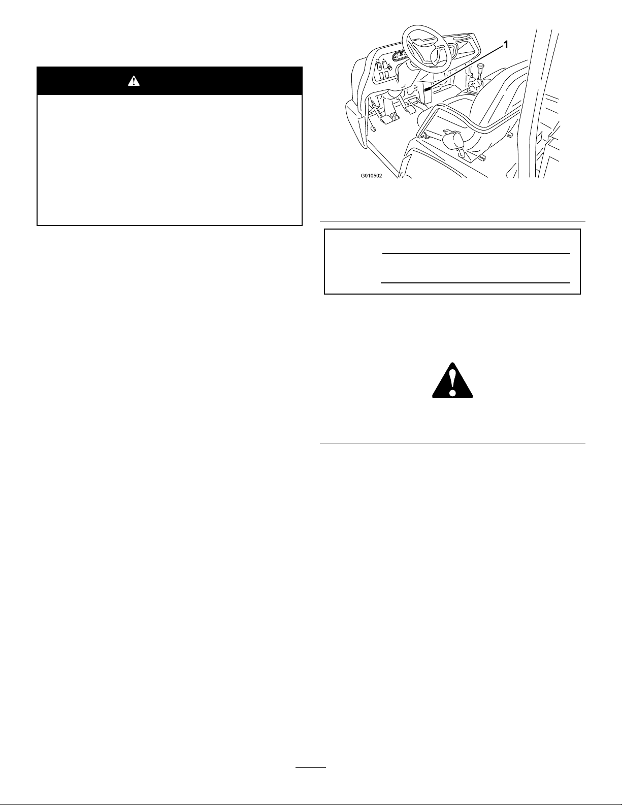
106-6755
1.Enginecoolantunder
pressure.
2.Explosionhazard—read
theOperator'sManual.
1.Warning—donottouchthehotsurface.
1.Storedenergyhazard—readtheOperator'sManual.
3.Warning—donottouchthe
hotsurface.
4.Warning—readthe
Operator'sManual.
115-2047
93-9879
115-7740
1.Warning—maximumtrailerweightis680kg(1500lb);
maximumtongueweightis90kg(200lb).
2.Warning—trailerbrakesarerequiredwhentowinggreater
than680kg(1500lb).Maximumtrailerweightwithtrailer
brakesis1591kg(3500lb)maximumtongueweightwith
trailerbrakesis273kg(600lb).
115-7756
1.Highowhydraulics—engaged
7
Page 8
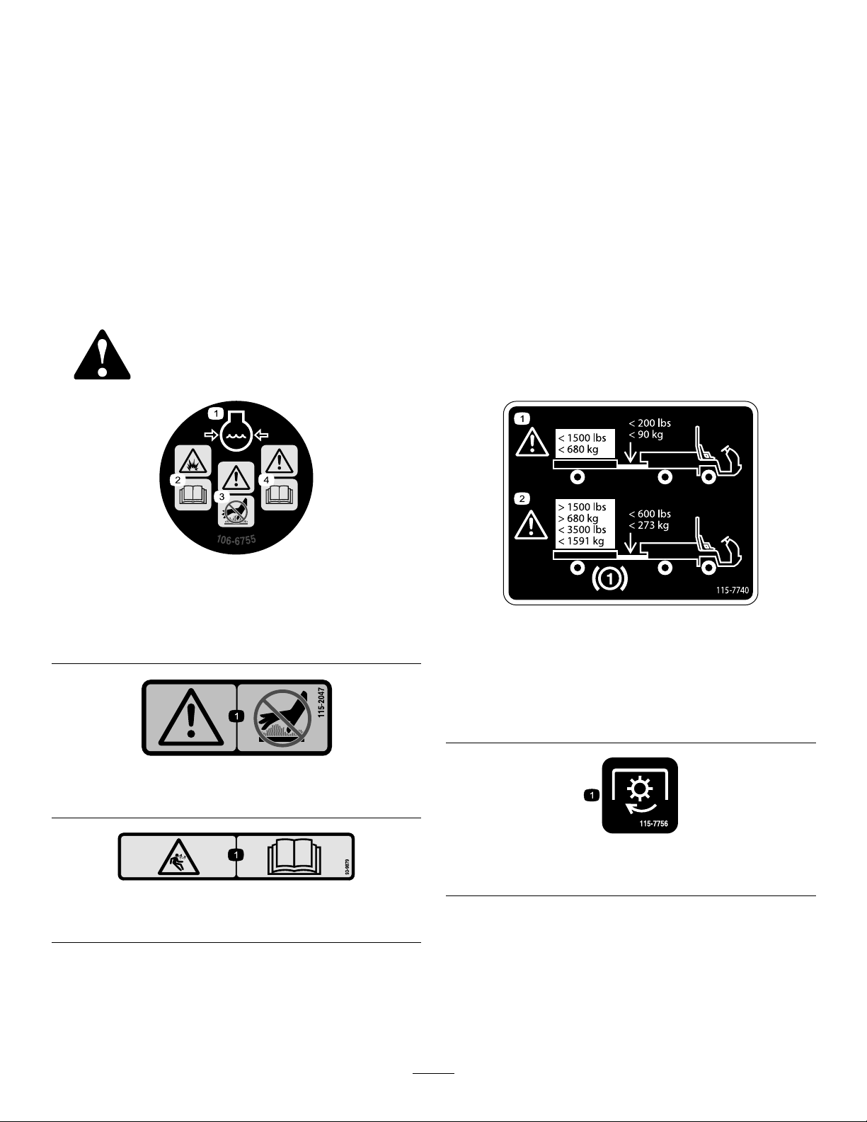
115-7723
93-9899
1.Warning—thehydraulicoilpressureis124bar(1800psi).
2.CouplerA
3.CouplerB
93-9899
1.Crushinghazard—installthecylinderlock.
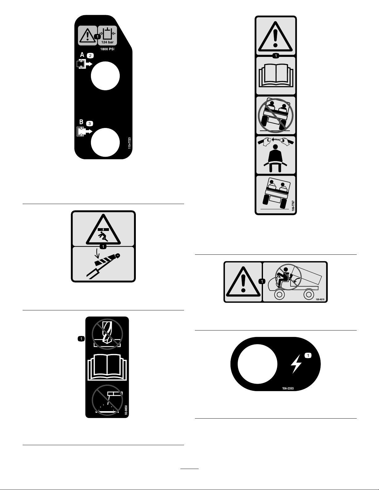
106-7767
1.Warning—readtheOperator'sManual;avoidtippingthe
machine;weartheseatbelt;leanawayfromthedirection
themachineistipping.
105-4215
1.Warning—avoidpinchpoints.
93-9850
1.Donotrepairorrevise—readtheOperator'sManual.
106-2353
1.Electricalpowerpoint
8
Page 9
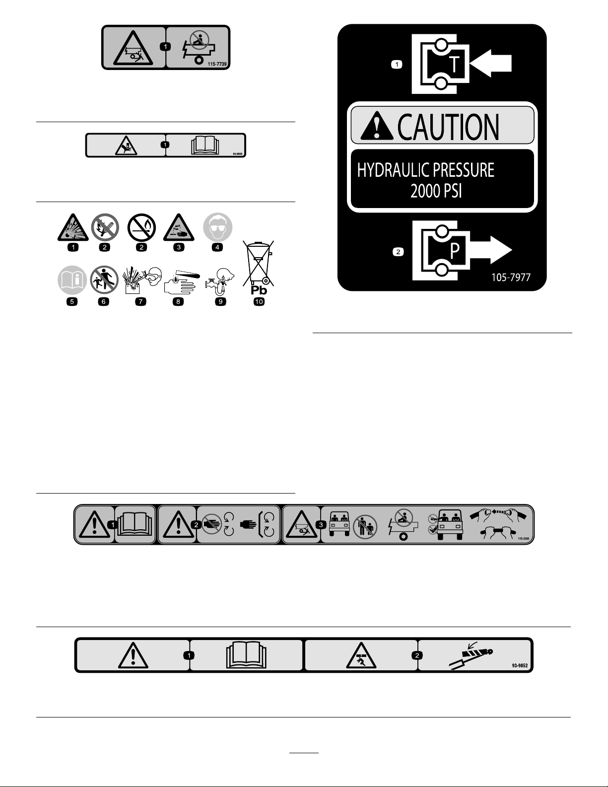
115-7739
1.Falling,crushinghazard,bystanders—noriderson
machine.
93–9868
1.Crushinghazardofhand—readtheOperator’sManual.
BatterySymbols
Someorallofthesesymbolsareonyourbattery .
105–7977
1.Tank2.Pressure
1.Explosionhazard
2.Nore,opename,or
smoking.
3.Causticliquid/chemical
burnhazard
4.Weareyeprotection9.Flusheyesimmediately
5.ReadtheOperator's
Manual.
6.Keepbystandersasafe
distancefromthebattery.
7.Weareyeprotection;
explosivegasescan
causeblindnessandother
injuries
8.Batteryacidcancause
blindnessorsevereburns.
withwaterandgetmedical
helpfast.
10.Containslead;donot
discard.
115-2282
1.Warning—readtheOperator'sManual.
2.Warning—stayawayfrommovingpartsandkeepallguardsandshieldsinplace.
3.Crushing/dismembermenthazardofbystanders—keepbystandersasafedistancefromthevehicle,donotcarrypassengersin
thecargobed,keeparmsandlegsinsideofthevehicleatalltimes,anduseseatbeltsandhandholds.
93-9852
1.Warning—readtheOperator’sManual.2.Crushinghazard—installthecylinderlock.
9
Page 10
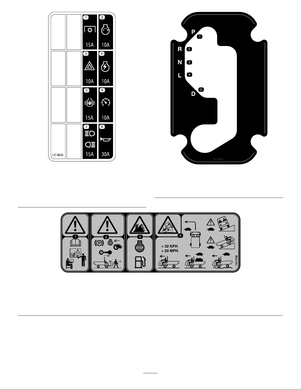
127–8626
1.Powertake-off—15A5.Differentiallock—15A
2.Enginestart—10A
3.Hazards—10A7.Headlightsandrear
4.Engineignition—10A8.Horn—30A
6.Speedometer—10A
lights—15A
127–8760
1.Park4.Lowgear
2.Reverse5.Drive
3.Neutral
115-7746
1.Warning—donotoperatethismachineunlessyouaretrained.
2.Warning—locktheparkingbrake,stoptheengine,and
removetheignitionkeybeforeleavingthemachine.
3.Firehazard—stoptheenginebeforefueling.
4.Tippinghazard—slowdownandturngradually,usecaution
anddriveslowlywhendrivingonslopes,donotexceed32
kph(20mph),anddriveslowlyoverroughterrainorwhen
carryingafullorheavyload.
10
Page 11
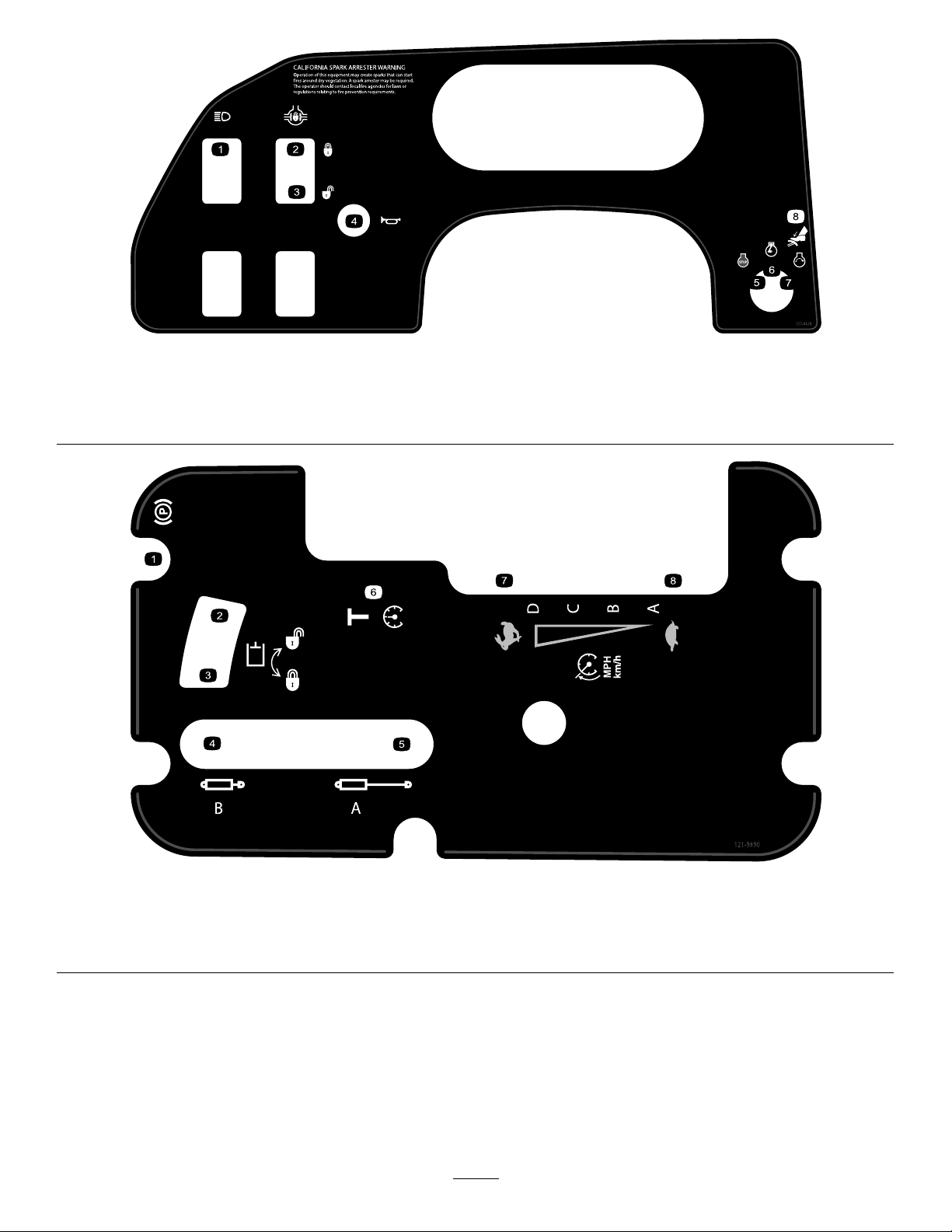
127-8620
1.Headlights4.Horn7.Engine—start
2.Differentiallock—lock
3.Differentiallock—unlock
5.Engine—stop8.Brake
6.Engine—run
1.Parkingbrake
2.Unlock—hydraulicsystem
3.Lock—hydraulicsystem6.Transport
121-9890
4.Cylinderretract
5.Cylinderextend8.Slow
11
7.Fast
Page 12

Setup
LooseParts
Usethechartbelowtoverifythatallpartshavebeenshipped.
ProcedureDescription
Steeringwheel
1
2
3
4
5
Cover
Washer(5/8inch)
ROPSframe
Flange-headbolt(1/2x1-1/4inch)
Nopartsrequired
Nopartsrequired
Nopartsrequired
MediaandAdditionalParts
Description
Operator'sManual
PartsManual1
OperatorTrainingMaterial
CVTKit121-9853
Qty.
Qty.
1
1
1
1
6
–
–
–
1
1
1
Readbeforeoperatingthevehicle.
Usetoreferencepartnumbers.
Viewbeforeoperatingthemachine.
ConnectingtheCVTIntakeDuct(TCandHModelsOnly)
Installthesteeringwheel.
MounttheROPS(RolloverProtection
System).
Connectthebattery.
Connectthecontinuouslyvariable
transmissionintakeduct.
Checktheengineoil,transaxle/hydraulic
uid,coolant,andbrakeuidlevels.
Use
Use
CVTAdapter127-8750
Note:Determinetheleftandrightsideofthemachinefromthenormaloperatingposition.
1
1
ConnectingtheCVTIntakeDuct(TCandHModelsOnly)
4.Securethesteeringwheeltotheshaftwiththenutand
tightenitto27–34N-m(20-25ft-lb).
5.Installthecoveronthesteeringwheel(Figure3).
InstallingtheSteeringWheel (TCandHModelsonly)
Partsneededforthisprocedure:
1
Steeringwheel
1
Cover
1
Washer(5/8inch)
Procedure
1.Ifthecoverisinstalled,removetheitfromthehubof
thesteeringwheel(Figure3).
2.Removethenutfromthesteeringshaft(Figure3).
3.Slidethesteeringwheelandwasherontothesteering
shaft(Figure3).
12
Page 13
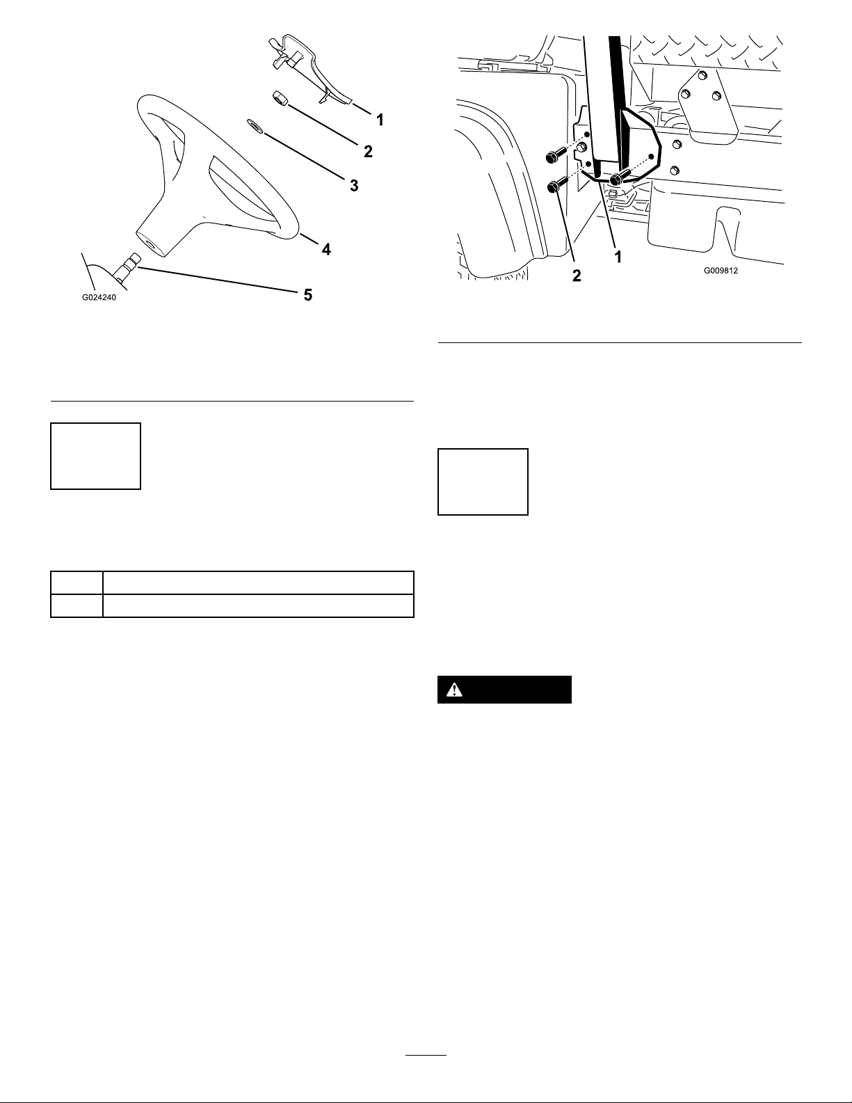
Figure3
1.Cover4.Steeringwheel
2.Nut
3.Washer(5/8inch)
5.Steeringshaft
2
Figure4
1.ROPSmountingbracket
3.SecureeachsideoftheROPSmountingbracketto
frameofthemachinewith3ange-headbolt(1/2x
1-1/4inch).
4.Torquetheange-headboltsto115N-m(85ft-lb).
2.Flange-headbolt
InstallingtheROPS
Partsneededforthisprocedure:
1
ROPSframe
6
Flange-headbolt(1/2x1-1/4inch)
Procedure
1.Applymedium-grade(service-removable)thread
lockingcompoundtothethreadsofthe6ange-head
bolts(1/2x1-1/4inch).
2.AligneachsideoftheROPSwiththemountingholes
oneachsideofframeofthemachineasshownin
Figure4.
3
ConnectingtheBattery(TC andHModelsonly)
NoPartsRequired
Procedure
WARNING
Incorrectbatterycableroutingcoulddamagethe
machineandcablescausingsparks.Sparkscan
causethebatterygassestoexplode,resultingin
personalinjury.
•Alwaysdisconnectthenegative(black)battery
cablebeforedisconnectingthepositive(red)
cable.
•Alwaysconnectthepositive(red)batterycable
rst.
1.Squeezethebatterycovertoreleasethetabsfromthe
batterybase(Figure5).
13
Page 14
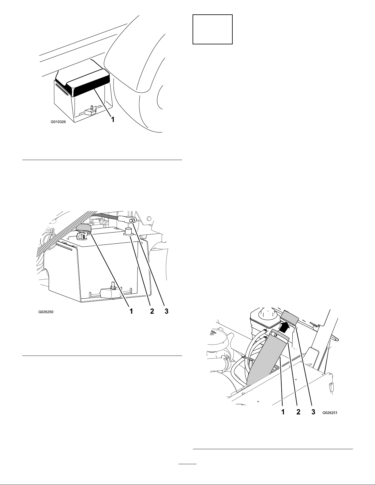
1.Batterycover
Figure5
4
ConnectingtheCVTIntake Duct(TCandHModelsonly)
NoPartsRequired
Procedure
Important:Removetheplasticbagcoveringtheendof
theCVTductbeforestartingtheengineofthemachine.
TheCVTkit121-9853andadapterkit127-8750isrequired
forthisprocedure.
1.Loosenthehoseclampsecuringtheplasticbagatthe
endoftheCVTintakehoseandremovethebag.
2.Removethebatterycoverfromthebatterybase(Figure
5).
3.Installthepositive-batterycable(red)ontothepositive
(+)terminalofthebatteryandsecurethecablewith
theboltsandnuts(Figure6).
Figure6
1.Insulatorboot
(positive-batterycable)
2.Negative-batterypost
3.Negative-batterycable
Note:Discardplasticbag.
2.Raisethecargoboxbyperformingthefollowing:
A.Settheparkingbrake;refertoParkingBrake
(page16).
B.Starttheengine;refertoStartingtheEngine(page
27).
C.Movethehydraulic-liftleverbackwardtoraisethe
cargobox;refertoHydraulicLiftLever(page16).
D.Shutofftheengine;refertoStoppingtheEngine
(page27).
E.Removethebedsupportfromthestoragebrackets
onbackoftheROPSpanelandinstallthesupport
ontothecylinderrodofthebedliftcylinder;refer
toUsingtheBedSafetySupport(page36).
3.AligntheCVTintakehoseontotheintake-tube
connectoratthebacksideoftheROPSpaneland
tightenthehoseclamp(Figure7).
4.Slidetheinsulatorbootoverthepositiveterminal.
Note:Theinsulatorbootisusedtopreventapossible
short-to-groundfromoccurring.
5.Installthenegative-batterycable(black)ontothe
negative(–)terminalofthebatteryandsecurethecable
withboltsandnuts.
6.Alignthebatterycovertothebatterybase(Figure5).
7.Squeezethebatterycover,alignthetabstothebattery
base,andreleasethebatterycover(Figure5).
14
1.CVTintakehose
2.Hoseclamp
Figure7
3.Intake-tubeconnector
Page 15

4.Removethebedsupport,lowerthebed,shutoffthe
engine,andremovethekeyfromtheignitionswitch.
5
ProductOverview
Controls
Note:Determinetheleftandrightsidesofthemachine
fromthenormaloperatingposition.
CheckingtheFluidLevels
NoPartsRequired
Procedure
1.Checktheengineoillevelbeforeandaftertheengineis
rstoperated;refertoCheckingtheEngine-oilLevel
(page21).
2.Checkthetransmission-uidlevelbeforetheengineis
rstoperated;refertoCheckingtheTransmission-uid
Level(page47).
3.Checktheengine-coolantlevelbeforetheengineisrst
operated;referto(page).
4.Checkthebrakeuidlevelbeforetheengineisrst
operated;refertoCheckingtheBrakeFluid(page24).
AcceleratorPedal
Theacceleratorpedal(Figure8)givestheoperatortheability
tovarytheengineandgroundspeedofthevehiclewhenthe
transmissionisingear.Pressingthepedalincreasestheengine
speedandgroundspeed.Releasingthepedaldecreasesthe
enginespeedandgroundspeedofthemachine.
Figure8
1.Brakepedal2.Acceleratorpedal
BrakePedal
Usethebrakepedal(Figure8)toapplytheservicebrakes
tostoporslowthemachine.
CAUTION
Brakesthatarewornornotcorrectlyadjustedmay
resultinpersonalinjury.Ifthebrakepedaltravels
towithin3.8cm(1-1/2inches)ofthemachineoor
board,adjustorrepairthebrakes.
TransmissionLever
Usethetransmissionlever(Figure9)toshiftthetransmission
betweenP(park),R(reverse),N(neutral),L(lowforward),
andD(drive)groundoperation.
Important:DonotshiftthetransmissiontotheReverse,
Low,orDrivegearunlessthevehicleisstandingstilland
theengineisatlowidle.Otherwiseyoumaydamage
thetransmission.
15
Page 16
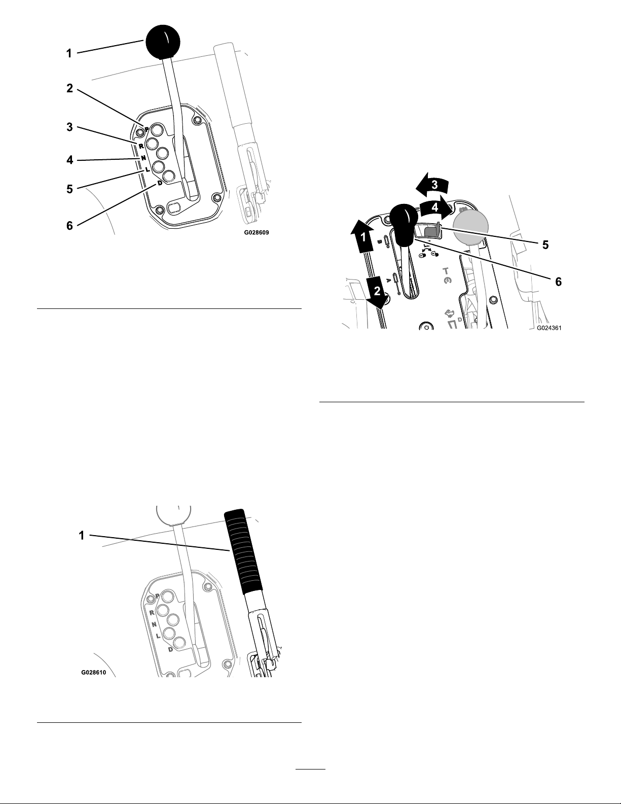
Figure9
HydraulicLiftLever
Thehydraulicliftraisesandlowersthebed.Movethe
hydraulicliftleverrearwardtoraisethebed,andforwardto
lowerit(Figure11).
Important:Whenloweringthebed,holdtheleverinthe
forwardpositionfor1or2secondsafterthebedcontacts
theframetosecureitintheloweredposition.Donot
holdthehydraulicliftineithertheraiseorlowerposition
formorethan5secondsoncethecylindershavereached
theendoftheirtravel.
1.Transmissionlever
2.P(park)5.L(lowforward)
3.R(reverse)6.D(drive)
4.N(neutral)
ParkingBrake
Whenevertheengineisshutoff,settheparkingbrake(Figure
10)topreventaccidentalmovementofthevehicle.
•Tosettheparkingbrake,pullbackontheparking-brake
lever.
•Toreleasetheparkingbrake,pushtheleverforward.
Note:Releasetheparkingbrakebeforemovingthe
vehicle.
•Ifyouparkthevehicleonasteepuphillordownhillgrade,
shiftthetransmissionintoP(park)andsettheparking
brake.Placechocksatthedownhillsideofthewheels.
Figure11
1.Lowerthebed4.Unlocked
2.Raisethebed
3.Locked
5.Hydraulic-liftlock
6.Hydraulic-liftlever
Hydraulic-liftLock
Thehydraulic-liftlocklockstheliftleversothatthehydraulic
cylindersdonotoperatewhenthevehicleisnotequipped
withabed(Figure11).ItalsolockstheliftleverintheOn
positionwhenusingthehydraulicsforattachments.
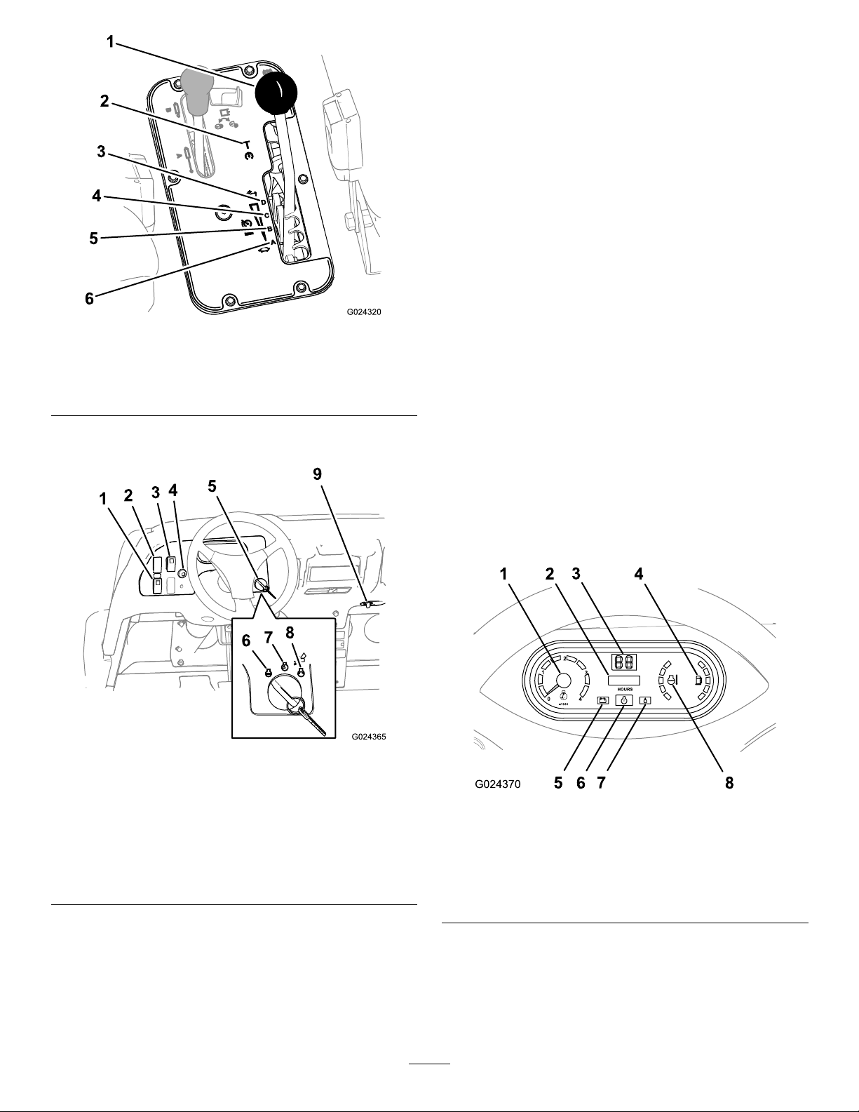
Speed-rangeLever
Usethespeed-rangelever(Figure12)toselect1of
the4work-speedrangesforprecisecontrolofthe
maximum-groundspeedoratransport-speedrangethatisfor
movingthemachinebetweenjobsites.
1.Parking-brakelever
Figure10
16
Page 17
LightSwitch
Pushthelightswitchdowntotoggletheheadlightsonorpush
thelightswitchuptotoggletheheadlightsoff(Figure13).
Differential-lockSwitch
Thedifferential-lockswitchallowsyoutolocktherearaxle
forincreasedtraction.Pushthedifferential-lockswitch
(Figure13)totogglethedifferentiallockonoroff.
Note:Youmaylockandunlockthedifferentialwhilethe
vehicleisinmotion.
HornButton(TCmodelsonly)
Pressingthehornbuttonactivatesthehorn(Figure13).
Figure12
1.Speed-rangelever4.C(mid-highrange)
2.T(transportrange)5.B(mid-lowrange)
3.D(highrange)6.A(lowrange)
DashboardSwitches
IgnitionSwitch
Usetheignitionswitch(Figure13)tostartandstopthe
engine.Ithas3positions:Off,Run,andStart.Rotatethekey
clockwisetotheStartpositiontoengagethestartermotor.
Releasethekeywhentheenginestarts.Thekeywillmove
automaticallytotheOnposition.Toshuttheengineoff,
rotatethekeycounterclockwisetotheOffposition.
PowerPoint
Usethepowerpointsocket(Figure13)topoweroptional
12-voltelectricalaccessories.
InstrumentCluster
Figure13
1.Highowhydraulicsswitch
(TCmodelsonly)
2.Lightswitch
3.Differentialswitch8.Start
4.Hornbutton(TCmodels
only)
5.Ignitionswitch
HighFlowHydraulicsSwitch(TCmodelsonly)
6.Off
7.On
9.Powerpoint
Pushtheswitchdowntostartthehighowhydraulicsand
pushtheswitchuptoshutoffthehydraulics(Figure13).
Note:Youmustsetthehighowhydraulicsswitchtothe
Offpositioninordertostarttheengine.
Figure14
1.Tachometer
2.Hourmeter
3.Speedometer
4.Fuelgauge
Tachometer
5.Charge-indicatorlight
6.Check-enginelight
7.Low-oilpressurelight
8.Coolant-temperature
gauge
Thetachometerdisplaysthespeedoftheengine(Figure14).
Note:Thewhitetriangleindicatesthedesiredenginespeed
for540rpmPTOoperation.
17
Page 18
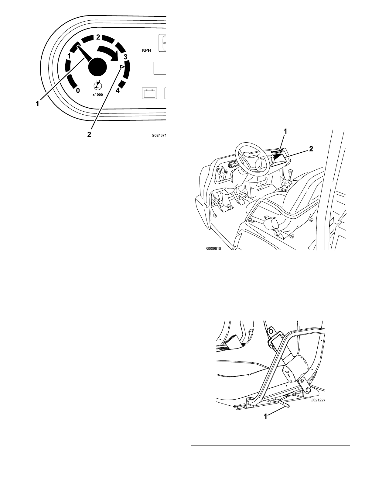
Figure15
temperaturelightwillilluminateredandashiftheengine
overheats.
FuelGauge
Thefuelgaugeshowstheamountoffuelinthetank.It
displaysonlywhenignitionswitchisintheOnposition
(Figure14).Theredsegmentofthedisplayindicateslow
fuellevelandtheashing-redlightindicatesthatthefuelin
thetankisnearempty .
PassengerHandHold
Thepassengerhandholdislocatedonthedashboard(Figure
16).
1.Enginespeed(inrpm)2.3300rpmfor540rpmPTO
operation
HourMeter
Thehourmeterindicatesthetotalhoursofmachine
operation.Thehourmeter(Figure14)startstofunction
wheneverthekeyswitchisrotatedtotheOnpositionorif
theengineisrunning.
Speedometer
Thespeedometerregistersthegroundspeedofthevehicle
(Figure14).Thespeedometerisinmph,butyoucaneasily
convertedthespeedometertokm/h.RefertoConverting
theSpeedometer(page54).
CheckEngineLight
Thecheckenginelight(Figure14)willilluminatetonotify
operatorofaenginemalfunction.
ContactyourauthorizedToroservicedealer.
OilPressureWarningLight
Figure16
1.Passengerhandhold
2.Storagecompartment
SeatAdjustingLever
Usetheseatadjustmentlevertoadjusttheseatforwardor
backwardforoperatorcomfort(Figure17).
Theoilpressurewarninglightilluminates(Figure14)ifthe
engineoilpressuredropsbelowasafelevelwhiletheengine
isrunning.
Important:Ifthelightickersorremainson,stopthe
vehicle,turnofftheengine,andchecktheoillevel.Ifthe
oillevelwaslow,butaddingoildoesnotcausethelight
togooutwhentheengineisstarted,turntheengine
offimmediatelyandcontactyourAuthorizedService
Distributorforassistance.
CoolantT emperatureGaugeandLight
Thecoolanttemperaturegaugedisplaysthecoolant
temperatureoftheengine.Thelightoperatesonlywhenthe
ignitionswitchisinOnposition(Figure14).Thecoolant
Figure17
1.Seat-adjustinglever
18
Page 19

Specications
Note:Specicationsanddesignaresubjecttochange
withoutnotice.
Dimensions
OverallWidth160cm(63inches)
withoutbed—326cm(128inches);
OverallLength
BaseWeight(Dry)
RatedCapacity
(includes91kg(200
lb)operator,91kg
(200lb)passengerand
loadedattachment)
MaximumGross
VehicleWeight
TowCapacityTongueweight:272kg(600lb);
GroundClearance18cm(7inches)withnoload
WheelBase
WheelTread(center
linetocenterline)
Height
withfullbed—331cm(130inches);
with2/3bedinrearmounting
location—346cm(136inches)
Model07390—866kg(1905lb);
Model07390H—866kg(1905lb);
Model07390TC—887kg(1951lb)
Model07390—1498kg(3295lb);
Model07390TC—1477kg(3249lb);
Model07090H—1498kg(3298lb)
2363kg(5210lb)
Maximumtrailerweight:1587kg
(3,500lb)
118cm(70inches)
Front:117cm(46inches);Rear:121
cm(48inches)
191cm(75inches)totopofROPS
Operation
Note:Determinetheleftandrightsidesofthemachine
fromthenormaloperatingposition.
CAUTION
Youmaybeinjuredorkillediftheraisedbedofthe
machinefallsonyou.
Beforeworkingunderaraisedbed,removeany
cargoandpositionthesafetysupportonthefully
extendedcylinderrod.
OperatingtheCargoBox
RaisingtheCargoBox
WARNING
Drivingthevehiclewiththecargoboxraisedmay
causethevehicletotiporrolleasier.Thebox
structuremaybecomedamagedifyouoperatethe
vehiclewiththeboxraised.
•Onlyoperatethevehiclewhenthecargoboxis
down.
•Afterdumpingaload,lowerthecargobox.
Attachments/Accessories
AselectionofToroapprovedattachmentsandaccessoriesis
availableforusewiththemachinetoenhanceandexpand
itscapabilities.ContactyourAuthorizedServiceDealeror
Distributororgotowww .Toro.comforalistofallapproved
attachmentsandaccessories.
CAUTION
Ifaloadisconcentratednearthebackofthecargo
boxwhenyoureleasethelatches,thetailgatemay
unexpectedlytipopen,injuringyouorbystanders.
•Centertheloadinthecargobox,ifpossible.
•Ensurethatnooneisleaningovertheboxor
standingbehinditwhenreleasingthetailgate
latches.
•Removeallcargofromtheboxbeforeliftingthe
boxuptoservicethemachine.
1.Settheparkingbrake;refertoParkingBrake(page16).
2.Starttheengine;refertoStartingtheEngine(page27).
3.Movetheleverbackwardtoraisethecargoboxtothe
desiredposition.(Figure18).
Note:Ifyouaremaintainingthemachineandneedto
havetheboxraised,securetheboxwiththebedsafety
support;refertoUsingtheBedSafetySupport(page
36).
19
Page 20
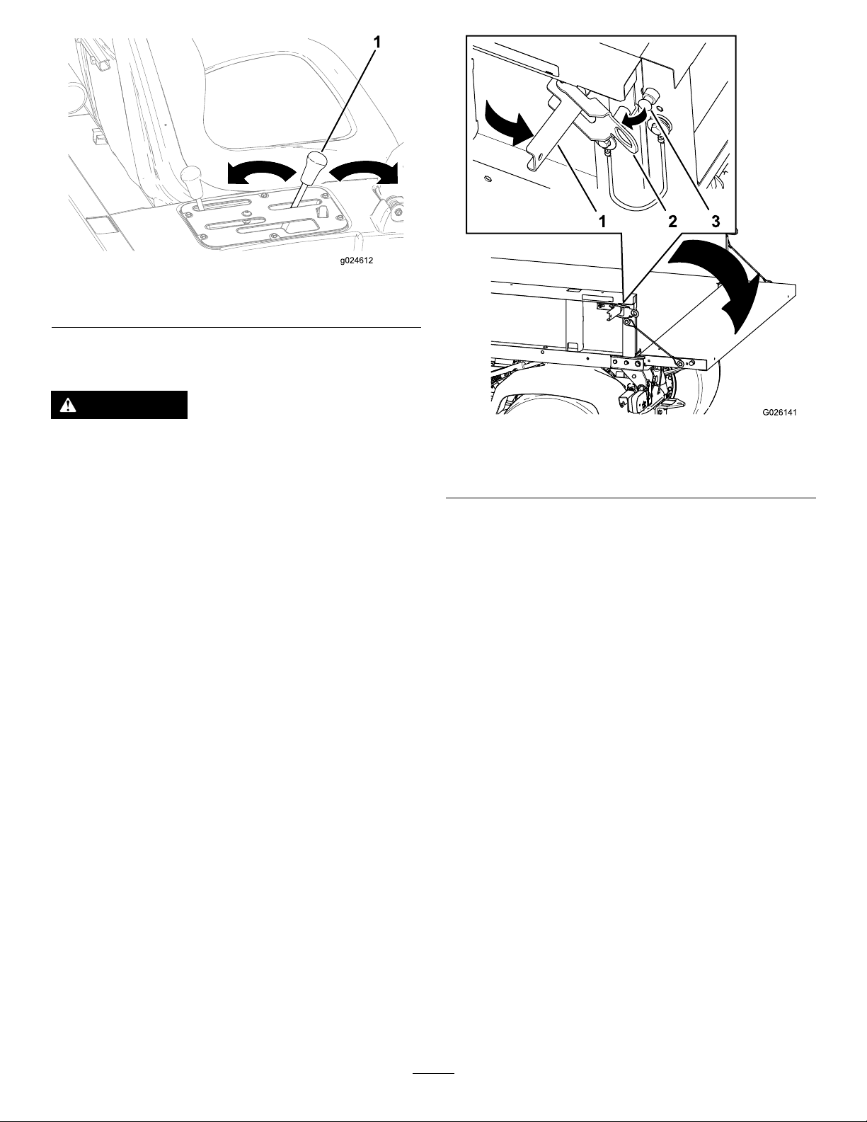
Figure18
1.Cargo-boxlever
LoweringtheBox
WARNING
Theweightoftheboxmaybeheavy.Handsor
otherbodypartscouldbecrushed.
Keephandsandotherbodypartsclearwhen
loweringthebox.
Figure19
1.Latchhandle3.Latchpin
2.Latchgate
1.Ensurethattheparkingbrakeisset;refertoParking
Brake(page16).
2.Ifthebedsupportisinstalled,removetheit;referto
UsingtheBedSafetySupport(page36).
3.Starttheengine;refertoStartingtheEngine(page27).
4.Movetheleverforwardtolowerthecargobox(Figure
18).
OpeningtheTailgate
1.Ensurethatthecargoboxisdownandlatched.
2.Openthelatchesontheleftandrightsideofthecargo
box(Figure19)andlowerthetailgate.
CheckingtheFluidLevels
PreparingtoChecktheFluidLevels
1.Movethemachinetoalevelsurface.
2.ShiftthetransmissiontotheParkposition,shutoff
theengine,settheparkingbrake,andremovethekey
fromtheignitionswitch.
3.Allowthemachinetocoolbeforeyouchecktheuid
levelsofthemachine.
4.Checkthefollowing:
Note:Checkingtheengineoil,hydraulicuidlevel,or
coolantlevelrequiresraisingandloweringthecargo
boxofthemachine;refertoOperatingtheCargoBox
(page19).
•CheckingtheEngine-oilLevel(page21)
•CheckingtheHydraulicFluid(page22)
•(page)
•CheckingtheBrakeFluid(page24)
20
Page 21

CheckingtheEngine-oilLevel
G016095
ServiceInterval:Beforeeachuseordaily—Checkthe
engine-oillevel.(Checktheoillevel
beforeandaftertheengineisrststarted
anddailythereafter.)
3.Removedipstickandchecktheleveloftheoil(Figure
21).
4.Iftheoillevelislow,removethellercap(Figure21)
andaddenoughoiltoraisetheleveltotheFullmark
onthedipstick.
OilType:ahigh-quality10W-30APIserviceclassication
SJorhigher.
RefertothetableinFigure20foroilviscosityaccording
ambientairtemperature.
Figure20
Note:Theengineisshippedwithapproximately2.0L(2.1
qt)ofoilinthecrankcase(includingtheoillter).
Note:Thebesttimetochecktheengineoiliswhenthe
engineiscoolbeforeithasbeenstartedfortheday.Ifthe
enginehasalreadybeenrun,shutitoffandwaitforatleast
10minutesbeforecheckingtheoillevel.
1.Removethedipstick(Figure21)andwipeitwitha
cleanrag.
Note:Whenaddingoil,removedipsticktoallow
properventing.Slowlypourtheoilintothellerneck,
andchecktheleveloftenduringthisprocess.Donot
overlltheenginewithoil.
Figure22
1.Notetheclearancebetweenthelldeviceandtheoilll
neck
Important:Whenaddingengineoilorllingoil,
theremustbeclearancebetweentheoillldevice
andtheoilllneckinthevalvecoverasshownin
Figure22.Thisclearanceisnecessarytopermit
ventingwhenaddingoil.
Figure21
1.Dipsticktube3.Fillercap
2.Fillerneck4.Dipstick
2.Insertthedipstickintothetubeandmakesurethat
itisseatedfully.
5.Installthellercapontothellerneck(Figure21).
6.Firmlyinstallthedipstickintothedipsticktube(Figure
21).
21
Page 22

CheckingtheHydraulicFluid
ServiceInterval:Beforeeachuseordaily(Checkthelevelof
hydraulicuidbeforetheengineisrst
startedanddailythereafter.)
HydraulicFluidType:MobilM15
HydraulicFluidCapacity:(Non-TCmodel):7.5l(2US
gallons)
HydraulicFluidCapacity:(Non-TCmodelwiththeHigh
FlowHydraulicKit(option)orTCModel):15.1l(4US
gallons)
WARNING
Hydraulicuidescapingunderpressurecan
penetrateskinandcauseinjury.
•Makesurethatallhydraulicuidhosesand
linesareingoodconditionandallhydraulic
connectionsandttingsaretightbefore
applyingpressuretothehydraulicsystem.
•Keepyourbodyandhandsawayfrompinhole
leaksornozzlesthatejecthighpressure
hydraulicuid.
Figure23
HydraulicFluidLevel(Non-TCmodels)
1.Cap
2.Dipstick3.Fillerneck
•Usecardboardorpapertondhydraulicleaks.
•Safelyrelieveallpressureinthehydraulicsystem
beforeperforminganyworkonthehydraulic
system.
•Seekimmediatemedicalattentionifuidis
injectedintoyourskin.
1.Cleantheareaaroundthellerneckandthecapofthe
hydraulicreservoir(Figure23andFigure24).
Figure24
HydraulicFluidLevel(Non-TCmodelwiththeHighFlow
HydraulicKit(option)orTCmodel)
1.Cap
22
2.Dipstick3.Fillerneck
Page 23

2.Removethecapanddipstickfromthellerneckofthe
1
G019522
reservoirandwipethedipstickcleanwitharag(Figure
23andFigure24).
3.Insertthedipstickintothellerneck;thenremoveit
andchecktheuidlevel(Figure23andFigure24).
•Non-TCmodel:theuidlevelshouldbebetween
thelowerindentedareaonthedipstick.
•Non-TCmodelwiththeHighFlowHydraulic
Kit(option)orTCmodel:theuidlevelshould
bebetweentheupperindentedareaonthedipstick.
4.Ifthelevelislow ,addthespeciedhydraulicuidinto
thereservoirtoraisetheleveltothemiddleofthe
indentedareaonthedipstick(Figure23andFigure24).
5.Installthedipstickandcaptothellerneckofthe
reservoir(Figure23andFigure24).
CheckingtheCoolantLevel
ServiceInterval:BeforeeachuseordailyChecktheCoolant
levelattheoverowreservoironly.Do
Notremovetheradiatorcap.(Checkthe
coolantlevelbeforetheengineisrst
startedanddailythereafter.)
Figure25
1.Coolantreservetank
Coolanttype:a50/50solutionofwaterandpermanent
ethyleneglycolantifreeze
1.Parkthemachineonalevelsurface.
CAUTION
Iftheenginehasbeenrunning,the
pressurized,hotcoolantcanescapeandcause
burns.
•Donotopentheradiatorcap.
•Allowtheenginetocoolatleast15minutes
oruntiltheradiatorcapiscoolenoughto
touchwithoutburningyourhand.
•Usearagwhenopeningthereservetank
cap,andopenthecapslowlytoallow
steamtoescape.
•Donotcheckthecoolantlevelatthe
radiator;checkthecoolantlevelonlyatthe
reservetank.
2.Checkthecoolantlevelatthereservetank(Figure25).
3.Ifcoolantislow ,removethereservetankcapandadda
50/50mixtureofwaterandpermanentethylene-glycol
antifreeze.
Note:Donotoverll.
4.Installthereserve-tankcap.
Note:Thecoolantshouldbeuptothebottomof
thellerneck.
23
Page 24

CheckingtheBrakeFluid
ServiceInterval:Beforeeachuseordaily—Checkthebrake
uidlevel.(Checkthelevelbeforethe
engineisrststartedanddailythereafter.)
Every1,000hours/Every2years(whichevercomes
rst)—Changethebrakeuid.
Brakeuidtype:DOT3brakeuid
Note:Thebrake-uidreservoirisshippedfromthefactory
lledwithDOT3brakeuid.
Thebrake-uidreservoirislocatedunderthehoodandbelow
thedash.
1.Parkthemachineonalevelsurface.
2.Removethehood;refertoRemovingtheHood(page
38).
3.Checktheuidlevelinthebrake-uidreservoir(Figure
26andFigure27).
Note:TheuidlevelshouldbeuptotheFullline
onthereservoir.
Figure27
1.Brake-uidreservoir
4.Iftheuidlevelislow,performthefollowing:
A.Cleantheareaaroundthecapforthereservoir
(Figure27).
B.Removethereservoircap(Figure27).
C.AddthespeciedbrakeuidtotheFulllineon
thereservoir(Figure27).
Note:Donotoverllthebrake-uidreservoir.
D.Installthecap(Figure27).
5.Installthehood;refertoRemovingtheHood(page38).
CheckingtheOilPressure WarningLight
ServiceInterval:Beforeeachuseordaily
Note:Ifyoujuststoppedtheengine,itmaytake1to2
minutesforthelighttocomeon.
1.Brake-uidreservoir
1.Applytheparkingbrake.
2.TurntheignitionkeytotheOnposition,butdonot
starttheengine.
Note:Theoilpressurelightshouldglowred.
Figure26
Note:Ifthelightdoesnotfunction,eitherabulb
isburnedoutorthereisamalfunctioninthesystem
whichmustberepaired.
24
Page 25

AddingFuel
DANGER
Fueltankcapacity:25L(6.5USgallons).
•Forbestresults,useonlyclean,fresh(lessthan30days
old),unleadedgasolinewithanoctaneratingof87or
higher((R+M)/2ratingmethod).
•ETHANOL:Gasolinewithupto10%ethanol(gasohol)
or15%MTBE(methyltertiarybutylether)byvolume
isacceptable.EthanolandMTBEarenotthesame.
Gasolinewith15%ethanol(E15)byvolumeisnot
approvedforuse.Neverusegasolinethatcontainsmore
than10%ethanolbyvolume,suchasE15(contains15%
ethanol),E20(contains20%ethanol),orE85(contains
upto85%ethanol).Usingunapprovedgasolinemay
causeperformanceproblemsand/orenginedamage
whichmaynotbecoveredunderwarranty.
•Donotusegasolinecontainingmethanol.
•Donotstorefueleitherinthefueltankorfuelcontainers
overthewinterunlessafuelstabilizerisused.
•Donotaddoiltogasoline.
DANGER
Incertainconditions,gasolineisextremely
ammableandhighlyexplosive.Areorexplosion
fromgasolinecanburnyouandothersandcan
damageproperty.
•Beforeremovingthefueltankcap,makesure
thatthevehicleispositionedonalevelsurface.
Openthefueltankcapslowly.
Incertainconditionsduringfueling,static
electricitycanbereleased,causingaspark,which
canignitethegasolinevapors.Areorexplosion
fromgasolinecanburnyouandothersandcan
damageproperty.
•Alwaysplacegasolinecontainersontheground
awayfromyourvehiclebeforelling.
•Donotllgasolinecontainersinsideavehicleor
onatruckortrailerbed,becauseinteriorcarpets
orplastictruckbedlinersmayinsulatethe
containerandslowthelossofanystaticcharge.
•Whenpractical,removegas-poweredequipment
fromthetruckortrailerandrefueltheequipment
withitswheelsontheground.
•Ifthisisnotpossible,thenrefuelsuch
equipmentonatruckortrailerfromaportable
container,ratherthanfromagasolinedispenser
nozzle.
•Ifyoumustuseagasolinedispensernozzle,,
keepthenozzleincontactwiththerimofthe
fueltankorcontaineropeningatalltimesuntil
fuelingiscomplete.
1.Cleantheareaaroundthefuel-tankcap(Figure28).
2.Removethefuel-tankcap(Figure28).
•Fillthefueltankoutdoors,inanopenarea,
whentheengineiscold.Wipeupanygasoline
thatspills.
•Neverllthefueltankinsideanenclosedtrailer.
•Donotllthefueltankcompletelyfull.Add
gasolinetothefueltankuntilthelevelis25mm
(1inch)belowthebottomofthellerneck.This
emptyspaceinthetankallowsthegasolineto
expand.
•Neversmokewhenhandlinggasoline,andstay
awayfromanopenameorwheregasoline
fumesmaybeignitedbyaspark.
•Storegasolineinanapprovedcontainerand
keepitoutofthereachofchildren.Neverbuy
morethana30-daysupplyofgasoline.
•Donotoperatethemachinewithouttheentire
exhaustsysteminplaceandinproperworking
condition.
Figure28
1.Fuel-tankcap
3.Fillthetanktoabout1inchbelowthetopofthetank,
(bottomofthellerneck),theninstallthecap.
Note:Donotoverllthefueltankwithfuel.
4.Wipeupanyfuelthatmayhavespilledtopreventa
rehazard.
25
Page 26

CheckingtheTirePressure
ServiceInterval:Beforeeachuseordaily
Themaximumairpressureinthefronttiresis220kPa(32
psi)andthereartiresis124kPa(18psi).
Checkthetirepressurefrequentlytoensureproperination.
Ifthetiresarenotinatedtothecorrectpressure,thetread
willwearprematurely.
Figure29showsanexampleoftirewearcausedbyunder
ination.
Figure29
1.Under-inatedtire
Figure30showsanexampleoftirewearcausedbyover
ination.
Figure31
1.Radiatorscreen
2.Latch
4.Ifsoequipped,rotatethelatchesandpivottheoil
coolerawayfromtheradiator(Figure32).
Figure32
1.Radiatorhousing3.Latches
2.Oilcooler
Figure30
1.Over-inatedtire
RemovingDebrisfromthe CoolingSystem
ServiceInterval:Beforeeachuseordaily(Cleanitmore
frequentlyindirtyconditions.)
1.Shutofftheengine.
2.Cleantheengineareathoroughlyofalldebris.
3.Unlatchandremovetheradiatorscreenfromthefront
oftheradiator(Figure31).
5.Cleantheradiator,oilcooler,andscreenthoroughly
withcompressedair.
Note:Blowdebrisawayfromtheradiator.
6.Installthecoolerandscreentotheradiator.
PreformingPre-startChecks
Safeoperationbeginsbeforetakingthevehicleoutforaday’ s
work.Y oushouldchecktheseitemseachtime:
•Checkthetirepressure.
Note:Thesetiresaredifferentthancartires,theyrequire
lesspressuretominimizeturfcompactionanddamage.
•Checkalluidlevelsandaddtheappropriateamountof
Torospecieduids,ifanyarefoundtobelow.
•Checkthefrontoftheradiator.Removeanydebrisand
cleantheradiatorscreen.
•Checkthebrakepedaloperation.
•Checktheoilpressurewarninglight.
•Checktoseethatthelightsareworking.
26
Page 27

•Turnthesteeringwheeltotheleftandrighttocheckthe
steeringresponse.
•Stoptheengineandwaitformovingpartstostop,then
checkforoilleaks,looseparts,andanyothernoticeable
malfunctions.
GearSpeed(kmh)Speed(mph)
R(reverse)
L(lowforward)
D(Drive)
0to210to13
0to180to11
0to320to20
Ifanyoftheaboveitemsarenotcorrect,notifyyourmechanic
orcheckwithyoursupervisorbeforetakingthevehicleout
fortheday.Yoursupervisormaywantyoutocheckother
itemsonadailybasis,soaskwhatyourresponsibilitiesare.
StartingtheEngine
Important:Donotattempttopushortowvehicletoget
itstarted.Damagetothedrivetraincouldresult.
Note:Referto(page).
1.Sitontheoperatorseatandengagetheparkingbrake.
2.DisengagethePTOandhighowhydraulics(ifso
equipped)andmovethehandthrottlelevertotheOff
position(ifsoequipped).
3.MovethetransmissionlevertotheP(park)position.
4.Ensurethatthehydraulic-liftleverisintheOffposition
(center).
5.Pressthebrakepedal.
Note:Keepyourfootofftheacceleratorpedal.
6.Insertkeyintoignitionswitchandrotateitclockwise
tostarttheengine.
Note:Avoidlongperiodsofengineidling.
Note:LeavingignitionswitchintheOnpositionfor
longperiodsoftimewithoutrunningtheenginewill
dischargethebattery.
StoppingtheVehicle
Note:Referto(page).
Tostopthevehicle,removeyourfootfromtheaccelerator
pedal,thenpressthebrakepedal.
StoppingtheEngine
Note:Referto(page).
1.Ensurethatthemachineisstopped.
2.MovethetransmissionlevertotheP(Park)position.
3.Settheparkingbrake.
4.RotatetheignitionkeytotheOffpositionandremove
thekeyfromtheswitch.
Note:Releasekeywhenenginestarts.
Note:Theengineoilpressurewarninglightshould
turnoff.
Important:Topreventoverheatingofthestarter
motor,donotengagestarterlongerthan15
seconds.After15secondsofcontinuouscranking,
wait60secondsbeforeengagingstartermotor
again.
DrivingtheVehicle
Note:Referto(page).
1.Pressthebrakepedal.
2.Releasetheparkingbrake.
3.Movethetransmissionlevertothedesiredgear.
4.Releasetheservicebrakeandgraduallypressinthe
acceleratorpedal.
Important:Alwaysstopthevehiclebeforeshifting
toreverseaforwardgearortoaforwardgearfrom
reverse.
Usethechartbelowtodeterminethegroundspeed
ofeachgearwhenoperatingthemachinewiththe
speed-rangecontrolintheT(transport)position.
UsingtheSpeed-rangeControl
Usetheleverofthespeed-rangecontroltolimitthe
maximumgroundspeedofthemachineforoperationsthat
requireaconstantspeedlikesprayingandtopdressing.The
speed-rangelever(Figure33)isusedtoselect1ofthe4
work-speedrangesthatareusedtolimitmaximumground
speedoratransport-speedrangethatisusedwhenyoumove
themachinebetweenjobsites.
Note:Youmustreleasetheacceleratorpedalinorderto
shiftbetweenspeedranges,butyoudonotneedtostopthe
machineinordertoshift.
•Movethespeed-rangeleverintothedetentfor
speedrangesA,B,C,andDwhenprecisecontrolof
maximum-groundspeedisdesired.
•Movethespeed-rangelevertotransportpositionby
movingthespeed-rangeleveroutofthedetentforrange
A,B ,C,orD,thenforwardtotheTposition.
Note:Usethespeed-rangecontroltolimitthe
maximum-groundspeedineachrangeby4to18kmh(2.5to
11mph)withthetransmissionleverintheLlow(forward)
positionor8to32kmh(5to20mph)withthetransmission
leverintheintheDdriveposition.
27
Page 28

Figure33
1.Speed-rangelever4.C(mid-highrange)
2.T(transportrange)5.B(mid-lowrange)
3.D(highrange)6.A(lowrange)
Thedifferentiallockcausestherearwheelstospinatthe
samespeed.Whenusingdifferentiallockyourabilitytomake
sharpturnsissomewhatrestrictedandmayscufftheturf.Use
thedifferentiallockonlywhenneededandatslowerspeeds.
Note:Vehiclemotionplusaslightturnisrequiredtoengage
ordisengagedifferentiallock.
•Pressthedifferential-lockswitchuptolockthedifferential
(Figure34).
Note:Thelightinthedifferential-lockswitchwill
illuminatewhentheswitchisinthelockposition.
•Pressthedifferential-lockswitchuptounlockthe
differential(Figure34).
UsingtheDifferentialLock
WARNING
Tippingorrollingthevehicleonahillcancausea
seriousinjury.
•Theextratractionavailablewiththedifferential
lockcanbeenoughtogetyouintodangerous
situationssuchasclimbingslopesthataretoo
steeptoturnaround.Beextracarefulwhen
operatingwiththedifferentiallockon,especially
onsteeperslopes.
•Ifthedifferentiallockisonwhenmakinga
sharpturnatahigherspeedandtheinsiderear
wheelliftsofftheground,theremaybealossof
controlwhichcouldcausevehicletoskid.Use
thedifferentiallockonlyatslowerspeeds.
CAUTION
Turningwiththedifferentiallockoncanresult
inlossofvehiclecontrol.Donotoperatewith
differentiallockonwhenmakingsharpturnsorat
highspeeds.
Thedifferentiallockincreasesthetractionofthevehicleby
lockingtherearwheelssothat1wheelwillnotspinout.
Thiscanhelpwhenyouhaveheavyloadstohaulonwet
turforslipperyareas,goinguphills,andonsandysurfaces.
Itisimportanttorememberthatthisextratractionisonly
fortemporarylimiteduse.Itsusedoesnotreplacethesafe
operationalreadydiscussedconcerningsteephillsandheavy
loads.
Figure34
1.Lockposition
(differential-lockswitch)
2.Unlockposition
(differential-lockswitch)
BreakinginaNewMachine
ServiceInterval:Aftertherst100hours
•Checktheuidandengineoillevelsregularlyandbealert
forindicationsofoverheatinginanycomponentofthe
vehicle.
•Afterstartingacoldengine,letitwarmupforabout15
secondsbeforeshiftingintogear.
Note:Allowmoretimetowarm-uptheenginewhen
operatingincoldambienttemperatures.
•Avoidracingtheengine.
•Toensureoptimumperformanceofthebrakesystem,
burnish(break–in)thebrakesbeforeuse.Toburnishthe
brakes,bringthevehicleuptofullspeed,applythebrakes
torapidlystopthevehiclewithoutlockingupthetires.
Repeatthis10times,waiting1minutebetweenstopsto
avoidoverheatingthebrakes.Thisismosteffectiveifthe
vehicleisloadedwith454kg(1000lb).
•Varyvehiclespeedsduringoperation.Avoidexcessive
idling.Avoidfaststartsandquickstops.
•Abreak–inoilfortheengineisnotrequired.The
originalengineoilisthesametypespeciedforregular
oilchanges.
•RefertoHeavyDutyOperation(page35)foranyspecial
low-hourchecks.
28
Page 29

CheckingtheInterlockSystem
ServiceInterval:Beforeeachuseordaily
Thepurposeoftheinterlocksystemistopreventtheengine
fromcrankingorstartingunlessthebrakepedalispressed
andthehydraulicliftleverintheNeutralposition.
1.Sitontheoperator’sseatandengagetheparkingbrake.
2.MovetheshiftlevertotheNeutralpositionandensure
thatthehydraulicliftleverisinthecenterposition.
3.SetthehighowhydraulicswitchtotheOnposition.
4.Pressbrakepedal.
CAUTION
Ifsafetyinterlockswitchesaredisconnectedor
damaged,themachinecouldoperateunexpectedly
causingpersonalinjury.
•Donottamperwiththeinterlockswitches.
•Checktheoperationoftheinterlockswitches
dailyandreplaceanydamagedswitchesbefore
operatingthemachine.
Note:RefertoAttachmentOperator’sManualforprocedures
oncheckingtheattachmentinterlocksystem.
VerifyingtheHydraulicLiftLever
InterlockSwitch
1.Sitontheoperator’ sseatandsettheparkingbrake.
2.MovetheshiftlevertotheNeutralposition,ensure
thatthehydraulicliftleverisinthecenterposition.
3.IfNon-TCmodelwiththeHighFlowHydraulicKit
(option)orTCmodel,setthehighowhydraulic
switchtotheOffposition.
4.Pressbrakepedal.
5.Movethehydraulicliftleverforwardandrotatethe
ignitionkeyclockwisetothestartposition.
5.Rotatetheignitionkeyclockwisetothestartposition.
Ifenginecranksorstarts,thereisamalfunctioninthe
interlocksystemthatmustberepairedbeforeoperating
vehicle.
TransportingtheMachine
Formovingthemachinelongdistances,useatrailer.Make
surethatthemachineissecuredtothetrailer.RefertoFigure
35andFigure36forthelocationofthetie-downpoints.
Important:Trailersweighingover680kg(1500lb)are
requiredtobeequippedwithtrailerbrakes.
Note:Loadthemachineonthetrailerwiththefrontofthe
machinefacingforward.Ifthatisnotpossible,securethe
hoodofthemachinetotheframewithastraporremovethe
hoodandtransportandsecureitseparately,otherwisethe
hoodmayblowoffduringtransport.
Ifenginecranksorstarts,thereisamalfunctioninthe
interlocksystemthatmustberepairedbeforeoperating
vehicle.
VerifyingtheBrakePedalInterlock
Switch
1.Sitontheoperator’ sseatandsettheparkingbrake.
2.MovetheshiftlevertotheNeutralposition,ensure
thatthehydraulicliftleverisinthecenterposition.
3.IfNon-TCmodelwiththeHighFlowHydraulicKit
(option)orTCmodel,setthehighowhydraulic
switchtotheOffposition.
4.Rotatetheignitionkeyclockwisetothestartposition.
Note:Donotpressthebrakepedal
Ifenginecranksorstarts,thereisamalfunctioninthe
interlocksystemthatmustberepairedbeforeoperating
vehicle.
VerifyingtheHighFlowSwitchInterlock
Non-TCmodelwiththeHighFlowHydraulicKit(option)
orTCmodel
Figure35
1.Eyeholeinframe(eachside)
Figure36
1.Axle2.Hitchplate
29
Page 30

TowingtheMachine
Incaseofanemergency ,themachinecanbetowedfora
shortdistance.However,Torodoesnotrecommendthisas
astandardprocedure.
Important:Ifmultiplevehiclesusethesame
attachment,crosscontaminationofthehydraulicuid
mayoccur.Changethehydraulicuidmorefrequently.
HydraulicControlPositions
WARNING
Towingatexcessivespeedscouldcausemachine
tolosesteeringcontrol.Nevertowmachinefaster
than8kph(5mph).
Towingthemachineisa2-personjob.Afxatowlineto
holesinthefrontframemember.MovetheshiftertoNeutral
andreleasetheparkingbrake.Ifthemachinemustbemoved
aconsiderabledistance,transportitonatruckortrailer.
Note:Thepowersteeringwillnotfunction,makingit
difculttosteer.
TowingaTrailerwiththe Machine
Thismachineiscapableofpullingtrailersandattachmentsof
greaterweightthanthemachineitself.
Severaltypesoftowhitchesareavailableforthismachine,
dependingonyourapplication.ContactyourAuthorized
Distributorfordetails.
•OffPosition
Thisisthenormalpositionforthecontrolvalvewhenit
isnotbeingused.Inthispositiontheworkportsofthe
controlvalveareblockedandanyloadwillbeheldbythe
checkvalvesinbothdirections.
•Raise(QuickCouplerAposition)
Thishydraulicliftleverpositionliftsthebedcylindersora
rearhitchattachmentbyapplyingRaisehydraulicpressure
throughquickcouplerA.Thisalsoallowsthereturnoilto
owthroughquickcouplerB,backthroughthecontrol
valve,andthenintothereservoir.Thisisamomentary
position;whenthehydraulicliftleverisreleased,aspring
returnsthelevertotheCenterOffposition.
Whenequippedwithatowhitchboltedontotherearaxle,
yourmachinecantowtrailersorattachmentswithagross
trailerweight(GTW)upto1587kg(3500lb).Alwaysloada
trailerwith60%ofthecargoweightinthefrontofthetrailer.
Thisplacesapproximately10%(272kg(600lb)max.)ofthe
grosstrailerweight(GTW)onthetowhitchofthemachine.
Trailerbrakesarerequiredwheneveryoutowatrailerover
680kg(1500lb)GTWistowedbehindthismachine.
Whenhaulingcargoortowingatrailer(attachment),donot
overloadyourmachineortrailer.Overloadingcancausepoor
performanceordamagetothebrakes,axle,engine,transaxle,
steering,suspension,bodystructure,ortires.
Important:Toreducepotentialfordrivelinedamage,
uselowrange.
Whentowing5thwheelattachments,likeafairwayaerator,
alwaysinstallthewheelybar(includedwiththefthwheelkit)
topreventthefrontwheelsfromliftingoffthegroundifthe
towedattachmentsmovementissuddenlyimpaired.
UsingtheHydraulicControl
Thehydrauliccontrolsupplieshydraulicpowerfromthe
machinepumpwhenevertheengineisrunning.Usethe
quickcouplersattherearofthemachinetoprovidehydraulic
powerforrearhitchattachments.
Figure37
1.QuickcouplerAposition2.QuickcouplerBposition
•Lower(QuickCouplerBposition)
Thispositionlowersthebedorarearhitchattachmentby
applyingLowerhydraulicpressurethroughquickcoupler
B.Thisalsoallowsthereturnoiltoowthroughquick
couplerA,backthroughthecontrolvalve,andtheninto
thereservoir.Thisisamomentaryposition;whenthe
hydraulicliftleverisreleased,aspringreturnsthecontrol
levertotheCenterOffposition.Momentarilyholding
andthenreleasingthehydraulicliftleverinthisposition
willprovideowtothequickcouplerB,whichprovides
Lowerhydraulicpressuretothebedcylindersorarear
hitchattachment.Whenthehydraulicliftleverisreleased,
theLowerhydraulicpressuretothebedcylindersora
rearhitchattachmentishydraulicallylocked.
Important:Ifusedwithahydrauliccylinder,
holdingthehydraulicliftleverintheLowerposition
30
Page 31

causestheoilowtogooverareliefvalve,whichcan
damagethehydraulicsystem.
•Onposition
ThispositionissimilartoLower(quickcouplerB
position).Italsodirectshydraulicoiltoquickcoupler
Bexceptthattheleverisheldinthispositionbythe
hydraulic-liftlockinthecontrolpanel.Thisallowsoil
toowcontinuouslytoequipmentthatusesahydraulic
motor.Usethispositiononlywhenyouareoperatingthe
machinewithanattachmentwithahydraulicmotor.
Important:Ifyouareusingthemachinewitha
hydrauliccylinderornoattachment,theOnposition
causestheoilowtogooverareliefvalve,whichcan
damagethehydraulicsystem.Usethispositiononly
momentarilyorwithamotorattached.
Important:Checkthehydraulicoillevelafter
installinganattachment.Checktheoperationof
theattachmentbycyclingitseveraltimestopurge
airfromsystem,thencheckthehydraulicoillevel.
Theattachmentcylinderwillslightlyaffecttransaxle
oillevel.Operatingthemachinewithlowoillevel
candamagethepump,remotehydraulics,power
steering,andthemachinetransaxle.
CAUTION
Hydraulicuidescapingunderpressurecan
havesufcientforcetopenetrateskinanddo
seriousdamage.Caremustbeusedwhen
connectingordisconnectinghydraulicquick
couplers.Stoptheengine,applytheparking
brake,lowertheattachment,andplacethe
remotehydraulicvalveintheoatdetent
positiontorelievehydraulicpressurebefore
connectingordisconnectingquickcouplers.
2.Pullthehosermlyfromthecoupler.
Important:Cleanandinstallthedustplugand
dustcoverstothequickcouplerendswhennot
inuse.
OperatingTips
OperatingCharacteristics
Themachineisdesignedwithsafetyinmind.Itusesfamiliar
automotivestylecontrols,includingthesteeringwheel,brake
pedal,andacceleratorpedal,.Itisimportanttoremember,
however,thatthismachineisnotapassengercar.Itisawork
vehicleandisdesignedforoffroaduseonly.
WARNING
Themachineisdesignedprimarilyasanoff-road
vehicleandisnotintendedforextensiveuseon
publicroads.
Occasionaluseonpublicroadwaysshouldonlybe
undertakenwithrespecttolocaltrafcregulations
andusinganyadditionalaccessoriesthatmaybe
requiredbylocallaw(includingbutnotlimitedto
lights,turnsignals,slowmovingvehicle(SMV)
sign,etc).
Themachinehasspecialtires,lowgearratios,alocking
differential,andotherfeaturesthatgiveitextratraction.
Thesefeaturesaddtotheversatilityofthevehiclebut,they
canalsogetyouintodangeroussituations.Youmustkeepin
mindthatthevehicleisnotarecreationvehicle,itisnotanall
terrainvehicle,and,itisdenitelynotmeantforstuntdriving
orhorsingaround.Itisaworkvehicle,notaplayvehicle.
Childrenshouldnotbeallowedtooperatethemachine.
Anyonewhooperatesthemachinemustbeproperlytrained.
ConnectingtheQuickCouplers
Important:Cleandirtfromquickcouplersbefore
connecting.Dirtycouplerscanintroducecontamination
intothehydraulicsystem.
1.Pullbackthelockingringonthecoupler.
2.Insertthehosenippleintothecoupleruntilitsnaps
intoposition.
Note:Whenattachingremoteequipmenttothequick
couplers,determinewhichsiderequirespressure,thenattach
thathosetoquickcouplerBwhichwillhavepressurewhen
thecontrolleverispushedforwardorlockedintheOn
position.
DisconnectingtheQuickCouplers
Note:Withboththemachineandattachmentturnedoff,
movetheliftleverbackandforthtoremovethesystem
pressureandtomakedisconnectingthequickcouplerseasier.
1.Pullbackthelockingringonthecoupler.
Thedriverandpassengershouldalwaysusetheseatbelts.
Ifyouarenotexperiencedatdrivingthemachine,practice
drivingitinasafeareaawayfromotherpeople.Besure
youarefamiliarwithallthemachine’scontrols,particularly
thoseusedforbraking,steering,andtransmissionshifting.
Learnhowyourmachinehandlesondifferentsurfaces.
Youroperatingskillswillimprovewithexperience,butasin
operatinganyvehicle,takeiteasyasyoubegin.Besureyou
knowhowtostopquicklyinanemergency.Ifyouneedhelp,
askyoursupervisorforassistance.
Manyfactorscontributetoaccidents.Youhavecontrolover
severalofthemostimportant.Youractions,suchasdriving
toofastforconditions,brakingtoofast,turningtoosharp,
andcombinationsofthese,arefrequentcauseofaccidents.
Oneofthemajorcausesofaccidentsisfatigue.Besureto
takeoccasionalbreaks.Itisveryimportantthatyoustay
alertatalltimes.
Neveroperatethemachine,oranyequipment,ifyou
areundertheinuenceofalcoholorotherdrugs.Even
31
Page 32

prescriptiondrugsandcoldmedicinescancausedrowsiness.
Readthelabelonthemedicineorcheckwithyourdoctoror
pharmacistifyouareunsureaboutacertainmedication.
Oneofthemostimportantrulestofollowistogoslowerin
unfamiliarareas.Itissurprisinghowmuchdamageandinjury
commonthingscancause.Treebranches,fences,wires,other
vehicles,treestumps,ditches,sandtraps,streams,andother
thingsfoundinmostparksandgolfcoursescanbehazardous
totheoperatorandpassenger.
Avoiddrivingwhenitisdark,especiallyinunfamiliarareas.If
youmustdrivewhenitisdark,besuretodrivecautiously,use
theheadlights,andevenconsideraddingadditionallights.
CarryingPassengers
Wheneveryouhaveapassengerridinginthemachinemake
sureheorsheiswearingtheseatbeltandholdingonsecurely .
Driveslowerandturnlesssharplybecauseyourpassenger
doesnotknowwhatyouaregoingtodonextandmaynotbe
preparedforturning,stopping,accelerating,andbumps.
Youandyourpassengershouldremainseatedatalltimes,
keepingarmsandlegsinsidethemachine.Theoperator
shouldkeepbothhandsonsteeringwheel,wheneverpossible,
andthepassengershouldusethehandholdsprovided(Figure
38andFigure39).
Figure39
1.Handholdandhiprestraint
Neverallowpassengersinthedumpboxoronany
attachments.Themachineismeanttohave1driverandonly
1passenger—nomore.
ControllingtheSpeedoftheVehicle
Speedisoneofthemostimportantvariablesleadingto
accidents.Drivingtoofastfortheconditionscancauseyou
tolosecontrolandhaveanaccident.Speedcanalsomakea
minoraccidentworse.Drivinghead-onintoatreeatslow
speedcancauseinjuryanddamage,but,drivingintoatreeat
highspeedcandestroythemachineandkillyouandyour
passenger.
Neverdrivetoofastfortheconditions.Ifthereisanydoubt
abouthowfasttodrive,slowdown.
Whenusingheavyattachments,morethan454kg(1000lb),
suchassprayers,topdressers,orspreaders,etc.,restrictyour
operatingspeedbyselectinglowrange.
1.Passengerhandhold
Figure38
EnsuringProperTurning
Turningisanotherimportantvariableleadingtoaccidents.
Turningtoosharplyfortheconditionscancausethemachine
tolosetractionandskid,oreventipover.
Wet,sandy,andslipperysurfacesmaketurningmoredifcult
2.Storagecompartment
andrisky .Thefasteryouaregoing,theworsethissituation
becomesso,slowdownbeforeturning.
Duringasharpturnathigherspeeds,theinsiderearwheel
mayliftofftheground.Thisisnotaawinthedesign,it
happenswithmostfourwheelmachinesincludingpassenger
cars.Ifthishappens,youareturningtoosharplyforthespeed
atwhichyouaretraveling.Slowdown!
EnsuringProperBraking
Itisgoodpracticetoslowdownbeforeyougetnearan
obstacle.Thisgivesyouextratimetostoporturnaway.
Hittinganobstaclecandamagethemachineanditscontents.
32
Page 33

Moreimportant,itcaninjureyouandyourpassenger.Gross
machineweighthasamajorimpactonyourabilitytostopor
turn.Heavierloadsandheavierattachmentsmakeamachine
hardertostoporturn.Theheaviertheload,thelongerit
takestostop.
Thebrakingcharacteristicsalsochangewithnobedor
attachmentonthemachine.Faststopsmaycausetherear
wheelstolockupbeforethefrontwheelslockup,whichmay
affectthecontrolofthemachine.Itisagoodideatodecrease
machinespeedwithnobedorattachment.
Turfandpavementaremuchslipperierwhentheyarewet.
Itcantake2to4timesaslongtostoponwetsurfacesas
ondrysurfaces.
OperatingtheMachineonHills
WARNING
Tippingorrollingthemachineonahillwillcause
seriouspersonalinjury.
•Donotoperatethemachineonsteepslopes.
•Ifenginestallsoryouloseheadwayonahill,
neverattempttoturnmachinearound.
•AlwaysbackstraightdownahillinReverse.
•NeverbackdowninNeutralusingonlythe
brakes.
Ifyoudrivethroughstandingwaterdeepenoughtogetthe
brakeswet,theywillnotworkwelluntiltheyaredry.After
drivingthroughwater,youshouldtestthebrakestomake
surethattheyworkproperly.Iftheydonot,driveslowly
whileputtinglightpressureonthebrakepedal.Thiswilldry
outthebrakes.
PreventingTipOvers
Themachineisequippedwitharollbar,hiprestraints,seat
belts,andhandhold.TheROPSsystem(RolloverProtection
System)usedonthemachinewillreducetheriskofserious
orfatalinjuryintheunlikelyeventofatipover,althoughthe
systemcannotprotecttheoperatorfromallpossibleinjuries.
ReplaceadamagedROPS,donotrepairit.Anyalterationof
theROPSmustbeapprovedbythemanufacturer.
Thebestwaytopreventaccidentsinvolvingutilitymachines
isthroughcontinuoussupervisionandtrainingofoperators
andpayingconstantattentiontotheareainwhichmachine
isbeingoperated.
Thebestwayforoperatorstopreventseriousinjuryordeath
tothemselvesorothers,istofamiliarizethemselveswiththe
properoperationoftheutilitymachine,tostayalertandto
avoidactionsorconditionswhichcouldresultinaaccident.
Intheeventofatipover,theriskofseriousinjuryordeath
willbereducediftheoperatorisusingtheROPSsystemand
seatbeltsandisfollowingtheinstructionsprovided.
•Neverdriveacrossasteephill,alwaysdrive
straightupordown.
•Avoidturningonahill.
•Don’tslamonthebrakes.Asuddenspeed
changecaninitiateatipover.
Useextracarewhenonhills.Nevergoonhillsthatare
extremelysteep.Stoppingwhilegoingdownahillwilltake
longerthanonlevelground.Turningwhilegoingupor
downahillismoredangerousthanturningonthelevel.
Makingturnswhilegoingdownhill,especiallywiththebrakes
on,andturninguphillwhiletraversingahillareparticularly
dangerous.Evenataslowspeedandwithoutaload,tipovers
aremorelikelyifyouturnonahill.
Ifyouhavetoturnwhileonahill,doitasslowlyand
cautiouslyaspossible.Nevermakesharporfastturnsona
hill.
Ifyoustallorbegintoloseheadwaywhileclimbingasteep
hill,quicklyapplythebrakes,shifttoNeutral,restartthe
engineandshifttoReverse.
Reducetheweightoftheloadifitisasteephilloriftheload
hashighcenterofgravity .Remember,loadscanshift,so
securethem.
Note:Themachinehasexcellenthill-climbingability.The
differentiallockwillincreasethisability.Hillclimbingtraction
canalsobeincreasedbyaddingweighttotherearofthe
machineinoneofthefollowingways:
•Addingweighttoinsideofbox,makingsurethatitis
secured
•Mountingwheelweightstorearwheels
•Addingliquidballast(calciumchloride)toreartires
•Nothavingapassengerinthefrontseat
33
Page 34

Maintenance
Determinetheleftandrightsidesofthemachinefromthe
normaloperatingposition.
Note:LookingforanElectricalSchematicorHydraulicSchematic
foryourmachine?Downloadafreecopyoftheschematicby
visitingwww.Toro.comandsearchingforyourmachinefrom
theManualslinkonthehomepage.
WARNING
Incertainconditions,gasolineisextremely
ammableandhighlyexplosive.Areorexplosion
fromgasolinecanburnyouandothersandcan
damageproperty.
Avoidrehazardsandhavereprotection
equipmentpresentintheworkarea.Donotusean
openametochecklevelorleakageoffuel,battery
electrolyte,orcoolant.Donotuseopenpansoffuel
orammablecleaninguidsforcleaningparts.
RecommendedMaintenanceSchedule(s)
CAUTION
Notproperlymaintainingthemachinecould
damageitand/orcauseinjurytoyouorbystanders.
Allowonlyqualiedandauthorizedpersonnelto
maintain,repair,adjust,andinspectthemachine.
CAUTION
Ifyouleavethekeyintheignitionswitch,someone
couldaccidentlystarttheengineandseriously
injureyouorotherbystanders.
Removethekeyfromtheignitionbeforeyoudoany
maintenance.
MaintenanceService
Interval
Aftertherst2hours
Aftertherst10hours
Aftertherst50hours
Aftertherst100hours
Beforeeachuseordaily
MaintenanceProcedure
•Torquethefrontandrearwheelnuts.
•Torquethefrontandrearwheelnuts.
•Checktheadjustmentoftheparkingbrake.
•Replacethehydrauliclter.
•Changetheengineoilandlter.
•Inspectopeningonlter.
•Checkthetransmissionuidlevel.
•Performthebreaking-inanewmachineguidelines.
•Checktheengine-oillevel.(Checktheoillevelbeforeandaftertheengineisrst
startedanddailythereafter.)
•Checkthehydraulic-uidlevel.(Checkthelevelofhydraulicuidbeforetheengine
isrststartedanddailythereafter.)
•Checkthelevelofthecoolant.ChecktheCoolantlevelattheoverowreservoir
only.DoNotremovetheradiatorcap.(Checkthecoolantlevelbeforetheengineis
rststartedanddailythereafter.)
•Checkthebrakeuidlevel.(Checkthelevelbeforetheengineisrststartedand
dailythereafter.)
•Checktheoil-pressurewarninglight.
•Checkthetirepressure.
•Removedebrisfromtheengineareaandradiator.(Cleanitmorefrequentlyin
dirtyconditions.)
•Checktheoperationoftheinterlocksystem.
Every50hours
Every100hours
•Checktheconditionofthebattery(every30daysifthebatteryisinstorage).
•Checkthebatterycableconnections.
•Greaseallbearingsandbushings(lubricatemorefrequentlyinheavyduty
applications).
•Checktheconditionofthetires.
•Checktheconstantvelocitybootsfordamageandleakinglubricant.
34
Page 35

MaintenanceService
Every200hours
Every400hours
Interval
MaintenanceProcedure
•Changetheair-cleanerlter(morefrequentlyindustyordirtyconditions).
•Changetheengineoilandlter.
•Inspectopeningonlter.
•Torquethefrontandrearwheelnuts
•Checktheuidlevelinthereservoirforthespeedcontrolcylinder.
•Checktheadjustmentoftheparkingbrake.
•Checktheadjustmentofthebrakepedal.
•Inspecttheserviceandparkingbrakes.
•Inspectorreplacethesparkplug.
•Replacethefuellter.
•Checkthefuellinesandconnections.
•Checkthefrontwheelalignment.
•Checkthetransmissionuidlevel.
•Checktheconditionofthedrivebelt.
•Cleantheclutches.
•Visuallyinspectthebrakesforwornbrakeshoes.
Every800hours
Every1,000hours
Yearly
•Replacethehydrauliclter.
•Changethehydraulicuidandcleanthestrainer.
•Changethebrakeuid.
•Drain/ushthefueltank.
•Flush/replacethecoolantsystemuid.
•Completealloftheyearlymaintenanceproceduresspeciedintheengineowner's
manual.
HeavyDutyOperation
Important:Ifthemachineissubjectedtoanyofthefollowingconditionslistedbelow,performthemaintenance
proceduresathalftherecommendedserviceinterval.:
•Operatingthemachineinadesertenvironment
•Operatingthemachineinacoldclimate—below0degreesC(32degreesF)
•Usingthemachinetotowatrailer
•Frequentlyoperatingthemachineondustyroads
•Usingthemachineforconstructionwork
•Afterusingthemachineinmud,sand,water,orsimilardirtyconditionsforanextendedtime
Note:Haveyourbrakesinspectedandcleanedassoonaspossibleaftereachuse.Thiswillpreventanyabrasivematerial
fromcausingexcessivebrakewear.
PremaintenanceProcedures
Manyofthesubjectscoveredinthismaintenancesectionrequireraisingandloweringthebed.Thefollowingprecautionsmust
betakenorseriousinjuryordeathcouldresult.
Important:Beforeservicingormakingadjustmentstothemachine,stoptheengine,settheparkingbrake,and
removethekeyfromtheignitionswitch.Removeanyloadmaterialfromthebedorotherattachmentbeforeworking
underaraisedbed.Neverworkunderaraisedbedwithoutpositioningthesafetysupportonafullyextended
cylinderrod.
35
Page 36

UsingtheBedSafetySupport
RemovingtheFullBed
Important:Alwaysinstallorremovethebedsupport
fromtheoutsideofthebed.
1.Raisethebeduntiltheliftcylindersarefullyextended.
2.Removethebedsupportfromthestoragebracketson
backoftheROPSpanel(Figure40).
Figure40
1.Bedsupport
Fullbedweight:approximately147.5kg(325lb)
1.Starttheengine.
2.Movethehydraulicliftleverforwardandlowerthe
beduntilthecylinderrodendsarelooseintheslots(
HydraulicLiftLever(page16)).
3.Releasetheliftleverandturnofftheengine.
4.Removethelynchpinsfromtheouterendsofthe
cylinderrodclevispins(Figure42).
3.Pushthebedsupportontothecylinderrod,making
surethatthesupportendtabsrestontheendof
cylinderbarrelandonthecylinderrodend(Figure41).
Figure41
1.Bedsupport3.Bed
2.Cylinderbarrel
4.Whennished,removethebedsupportfromthe
cylinderandinsertitintothebracketsonthebackof
theROPSpanel.
Important:Donottrytolowerbedwithbed
safetysupportoncylinder.
Figure42
1.Cylinderrodend
2.Bedmountingplate
3.Clevispin6.Frontslot(2/3bed)
4.Lynchpin
5.Rearslot(Fullbed)
5.Removetheclevispinssecuringthecylinderrodends
tothebedmountingplatesbypushingthepinstoward
theinside(Figure42).
6.Removethelynchpinsandclevispinssecuringthe
pivotbracketstotheframechannels(Figure42).
7.Liftthebedoffthemachine.
Important:Thefullbedweighsapproximately
147.5kg(325lb),sodonottrytoinstallorremove
itbyyourself.Useanoverheadhoistorgetthe
helpof2or3otherpeople.
8.Storethecylindersinthestorageclips.
9.Setthehydraulicliftlockleveronthemachinetothe
Lockposition;referto.
Note:Lockthelevertopreventtheliftcylindersfrom
extending.
36
Page 37

InstallingtheFullBed
Fullbedweight:approximately147.5kg(325lb)
Note:Ifthebedsideswillbeinstalledontheatbed,itis
easiertoinstallthembeforeinstallingthebedonthemachine.
Note:Ensurethattherearpivotplatesareboltedtothebed
frame/channelsothatlowerendanglestotherear(Figure43).
Figure43
1.Leftrearcornerofbed4.Clevispin
2.Framechannel5.Lynchpin
3.Pivotplate
intherearframechannelandinstall2clevispinsand
lynchpins(Figure44).
Important:Thefullbedweighsapproximately
147.5kg(325lb),sodonottrytoinstallorremove
itbyyourself.Useanoverheadhoistorgetthe
helpof2or3otherpeople.
3.Withthebedlowered,secureeachcylinderrodend,to
theappropriateslotsinthebedmountingplateswitha
clevispinandlynchpin.
Note:Youmayneedtostarttheenginetoextendor
retractthecylinderstoalignthemwiththeholes.Keep
ngersaway!
4.Inserttheclevispinfromoutsideofthebedwiththe
lynchpintowardtheoutside(Figure44).
Note:Therearslotsareforafullbedinstallationand
frontslotsarefora2/3bedinstallation.
Note:Theunusedslotcanbepluggedwithaboltand
anuttopreventassemblyerrors.
5.Starttheengineandengagethehydraulicliftleverto
raisethebed.
6.Releasetheliftleverandturnofftheengine.
7.Installthebedsafetysupporttopreventaccidental
loweringofthebed.RefertoUsingtheBedSafety
Support(page36).
8.Installthelynchpinstotheinsideendsoftheclevis
pins.
Note:Installthespacerbracketsandwearblocks(Figure44)
withthecarriageboltheadspositionedinsidethemachine.
Figure44
1.Wearblock
2.Spacerbracket
1.Ensurethattheliftcylindersarefullyretracted.
2.Carefullysetthebedontotheframeofthemachine,
aligningtherearbedpivotplateholeswiththeholes
3.Carriagebolt
Note:Iftheautomatictailgatereleasehasbeen
installedonthebed,ensurethatthefrontdumplink
rodhasbeenplacedontheinsideoftheleftsideclevis
pinbeforethelynchpinisinstalled.
JackingtheMachine
DANGER
Amachineonajackmaybeunstableandslipoffof
thejack,injuringanyonebeneathit.
•Donotstarttheenginewhilethemachineis
onajack.
•Alwaysremovethekeyfromtheswitchbefore
gettingoffofthemachine.
•Blockthetireswhenthemachineisonajack.
•Donotworkunderthemachinewithoutjackstands
supportingit.Themachinecouldslipoffajack,injuring
anyonebeneathit.
•Whenjackingupthefrontofthemachine,alwaysplacea
2x4block(orsimilarmaterial)betweenthejackandthe
machineframe.
•Thejackingpointatthefrontofthemachineisunderthe
frontcenterframesupport(Figure45).Attherearofthe
machine,thejackingpointisundertheaxle(Figure46).
37
Page 38

1.Frontjackingpoints
Figure45
Figure47
1.Hood
2.Pivotthebottomofthehoodupwarduntilyoucanpull
thetopmountingtabsfromtheframeslots(Figure47).
3.Pivotthetopofhoodforwardandunplugthewire
connectorsfromtheheadlights(Figure47).
Figure46
1.Rearjackingpoints
RemovingandInstallingthe Hood
RemovingtheHood
Removethehoodasfollows:
1.Whilegraspingthehoodintheheadlightopenings,lift
upthehoodtoreleasethelowermountingtabsfrom
theframeslots(Figure47).
4.Removethehood.
InstallingtheHood
1.Connectthelights.
2.Insertthetopmountingtabsintotheframeslots
(Figure47).
3.Insertthelowermountingtabsintotheframeslots
(Figure47).
4.Ensurethatthehoodisfullyengagedinthetop,sides,
andbottomgrooves.
38
Page 39

Lubrication
GreasingtheBearingsandthe Bushings
ServiceInterval:Every100hours(lubricatemorefrequently
inheavydutyapplications).
Lubricationtype:No.2general-purpose,lithium-based
grease
Important:Whengreasingthedriveshaftuniversal
shaftbearingcrosses,pumpgreaseuntilitcomesout
ofall4cupsateachcross.
1.Wipeeachgreasettingcleansothatforeignmatter
cannotbeforcedintothebearingorbushing.
Springtower(2);refertoFigure49
2.Connectthegreaseguntothegreasetting.
3.Pumpgreaseintoeachbearingorbushing.
4.Wipeoffanyexcessgrease.
Thegreasettinglocationsandquantitiesareasfollows:
•Balljoints(4);refertoFigure48
•Pivotmounts(2);refertoFigure48
•Steeringcylinder(2);refertoFigure48
•Tierods(2);refertoFigure48
Figure49
•Brake(1);refertoFigure50
•Throttle(1);refertoFigure50
Figure48
Figure50
39
Page 40

•DriveshaftU-joints(2);refertoFigure51
•Slidingyolk(1);refertoFigure51
Figure51
EngineMaintenance
ServicingtheAirFilter
ServiceInterval:Every200hours—Changetheair-cleaner
lter(morefrequentlyindustyordirty
conditions).
Inspecttheairlterandhosesperiodicallytomaintain
maximumengineprotectionandtoensuremaximumservice
life.Checktheair—ltercoverandhousingfordamage
whichcouldpossiblycauseanairleak.Replaceanydamaged
air-ltercomponents.
Inspectandchangetheairlterasdescribedinthefollowing
procedure:
1.Pullthelatchoutwardandrotatetheair-ltercover
counterclockwise(Figure52).
Figure52
1.Latch4.Dustvalve
2.Air-ltercover5.Air-lterhousing
3.Airlter
2.Beforeremovingthelter,uselowpressureair(40psi,
cleananddry)tohelpremovelargeaccumulationsof
debrispackedbetweentheoutsideoftheairlterand
theair-lterhousing.
Important:Avoidusinghighpressureair,which
couldforcedirtthroughthelterintotheintake
tract.Thiscleaningprocesspreventsdebrisfrom
migratingintotheintakewhentheprimarylter
isremoved.
3.Removeairlterfromthehousing(Figure52).
Note:Donotcleanausedlterelementbecauseyou
maydamageltermedia.
4.Wipecleantheinterioroftheair-ltercoverand
housing(Figure52).
5.Removetherubberdustvalvefromthecover(Figure
52).
40
Page 41

6.Cleanthedirtejectionportlocatedintheair-cleaner
cover,thedustvalvecavity,andthenreplacethedust
valve(Figure52).
7.Inspectthenewairlterforshippingdamage,checking
thesealingendofthelterandthebody.
Important:Donotuseadamagedelement.
8.Insertthenewairlterbyapplyinglightpressuretothe
outerrimoftheltertoseatitintheair-lterhousing
(Figure52).
9.Aligntheair-ltercoverwiththedustvalveatthe6
o’clockpositionwhenviewedfromtheleftendofthe
cover(Figure52).
10.Securethelatchoftheair-ltercover(Figure52).
Figure54
Note:Resettheindicatorifitisshowingred(ifso
equipped).
ChangingtheEngineOiland Filter
ServiceInterval:Aftertherst50hours
Every200hours
Engine-oilcapacity:2.0L(2.1quarts)ofoilinthecrankcase
(includingtheoillter)
OilType:ahigh-quality10W-30APIserviceclassication
SJorhigher.
ChooseaviscosityaccordingtothetableinFigure53.
1.Engine-oildrainplug
2.Forward
3.Removethedrainplugandletoilowintoadrainpan
(Figure54).
Note:Whentheoilstopsdraining,installthedrain
plug.
4.Removetheoillterfromthelteradapter(Figure55).
Figure53
1.Raisethebed(ifsoequipped)andplacethebedsafety
supportontheextendedliftcylindertoholdupthe
bed;refertoRaisingtheCargoBox(page19)and
UsingtheBedSafetySupport(page36).
2.Alignadrainpanwitha2.5L(3.0quarts)capacity
undertheoil-drainplugfortheengine(Figure54).
Figure55
1.Forward3.Filteradapter
2.Oillter
5.Wipecleanthesealingbaseoftheofthelteradapter
(Figure55).
6.Applyalightcoatofcleanoiltothesealofthenew
lter.
7.Installthelteruntilthegasketcontactsthesealingbase
ofthelteradapter,thentightenthelterclockwise
andadditional1/2to2/3ofaturn(Figure55).
Note:Donotovertightentheengineoillter.
8.Addthespeciedoiltothecrankcaseoftheengine;
refertoCheckingtheEngine-oilLevel(page21).
9.Lowerthebed;refertoLoweringtheBox(page20).
41
Page 42

ReplacingtheSparkPlug
G019300
1 2
4
3
FuelSystem
ServiceInterval:Every400hours
Sparkplugtype:ChampionRC14YC
Airgap:0.76mm(0.030inch)
1.Cleantheareaaroundthesparkplugsoforeignmatter
cannotfallintothecylinderwhenyouremovethe
sparkplug.
2.Pullwiresoffthesparkplugandremovetheplugs
fromthecylinderhead.
3.Checktheconditionofthesideelectrode,center
electrode,andcenterelectrodeinsulatortoensurethat
thereisnodamage(Figure56).
Important:Acracked,fouled,dirty,orotherwise
malfunctioningsparkplugmustbereplaced.Do
notsandblast,scrape,orcleanelectrodesby
usingawirebrushbecausegritmayeventually
releasefromtheplugandfallintothecylinderand
damagedtheengine.
Maintenance
ReplacingtheFuelFilter
ServiceInterval:Every400hours
1.Raisethebed(ifsoequipped)andinstallthebedsafety
supportontotheextendedliftcylindertoholdupthe
bed;refertoRaisingtheCargoBox(page19)and
UsingtheBedSafetySupport(page36).
2.Unplugthewiringharnessconnectorsfromthefuel
pump(Figure57).
3.Loosenthehoseclampanddisconnectthefuelline
fromthefuelpumpcap(Figure57).
Figure56
1.Sideelectrode
2.Centerelectrode4.Airgapat0.76mm(0.030
4.Settheairgap(Figure56)betweenthecenterandside
electrodesat0.81mm(0.032inch).
5.Installthecorrectlygappedsparkplugandtighten
themto24.5to29N-m(18to22ft-lb).
Note:Ifyoucannotuseatorquewrench,tightenthe
plugrmly.
6.Installthespark-plugwire.
3.Insulator
Figure57
1.Fuelpump
2.Hoseclamp
4.Removethefuel-pumpcapbyunthreaditfromthetop
inch)
ofthefueltank(Figure57).
Important:Donotallowthefuelpumpassembly
torotateduringtheremovalprocess.Ifthepump
rotates,itcanresultindamagetotheoatarm
assembly.
5.Removethefuelpumpassemblyandfuellterfrom
thetank(Figure57.
6.Removetheclampsecuringthefuellterhosetothe
fuelpumptting(Figure57).
7.Removethehosefromthetting(Figure57).
8.Insertthenewhoseclampontothenewfuellterhose.
9.Insertthehoseontothefuelpumpandsecurethe
clamp.
10.Inserttheassemblyintothefueltankandtightenthe
capto20to22N-m(175to200in-lb).
3.Fuelline/fuellter
Note:Note:V erifythattheoatarmdoesnotcontact
thefueltankwallsatanypointthroughthefullrange
ofmotion.
42
Page 43

11.Connectthewiresandsecurethehosewiththehose
clamp.
InspectingtheCarbonCanister
ElectricalSystem
Maintenance
AirFilter
ServiceInterval:Aftertherst50hours
Every200hours
1.Locatetheairlteronthebottomofthecarbon
canister(Figure58).
Figure58
1.Filteropening
2.Ensurethattheopeningonthebottomofthelteris
clearandopen.
ServicingtheFuses
Thefusesfortheelectricalsystemarelocatedunderthe
centerofthedashpanel(Figure59andFigure60).
Figure59
1.Fuses
InspectingtheFuelLinesand Connections
ServiceInterval:Every400hours/Yearly(whichevercomes
rst)
Every1,000hours/Every2years(whichevercomes
rst)
Inspectthefuellinesandconnectionsfordeterioration,
damage,orlooseconnections.
Figure60
1.Powertake-off—15A5.Differentiallock—15A
2.Enginestart—10A
3.Hazards—10A7.Headlightsandrear
4.Engineignition—10A8.Horn—30A
6.Speedometer—10A
lights—15A
43
Page 44

Jump-StartingtheMachine
WARNING
Jump-startingcanbedangerous.T oavoidpersonal
injuryordamagetoelectricalcomponentsin
machine,observethefollowingwarnings:
•Neverjump-startwithavoltagesourcegreater
than15voltsDC.Thiswilldamagetheelectrical
system.
•Neverattempttojumpstartadischargedbattery
thatisfrozen.Itcouldruptureorexplodeduring
jumpstarting.
•Observeallbatterywarningswhilejumpstarting
yourmachine.
•Ensurethatthemachineisnottouchingthe
jumpstartmachine.
Note:ThenegativeterminalhasNEGonthe
batterycover.Donotconnecttheotherendofthe
jumpercabletothenegativepostofthedischarged
battery—connectittotheengineorframe.
•Connectingcablestothewrongpostcould
resultinpersonalinjuryand/ordamagetothe
electricalsystem.
1.Squeezethebatterycovertoreleasethetabsfrom
batterybase,andremovethebatterycoverfromthe
batterybase(Figure61).
Figure62
1.Battery
4.Starttheengineofthemachinethatprovidesthe
electricalsourceforthejumpstart.
Note:Letmachinethatprovidestheelectricalsource
runafewminutes,thenstartyourengine.
5.Removethenegativejumpercablerstfromyour
engine,thenthebatteryintheothervehicle.
6.Installthebatterycovertothebatterybase.
Figure61
1.Batterycover
2.Connectajumpercablebetweenthepositivepostsof
the2batteries(Figure62).
Note:Thepositivepostmaybeidentiedbya+sign
ontopofthebatterycover.
3.Connecttheendoftheotherjumpercabletothe
negativeterminalofthebatteryintheothermachine.
Important:Donotconnectthejumpercableto
thefuelsystem.
44
Page 45

ServicingtheBattery
DriveSystem
ServiceInterval:Every50hours—Checktheconditionof
thebattery(every30daysifthebatteryis
instorage).
Every50hours—Checkthebatterycableconnections.
WARNING
CALIFORNIA
Proposition65Warning
Batteryposts,terminals,andrelated
accessoriescontainleadandleadcompounds,
chemicalsknowntotheStateofCalifornia
tocausecancerandreproductiveharm.
Washhandsafterhandling.
DANGER
Batteryelectrolytecontainssulfuricacid,whichisa
deadlypoisonandcausessevereburns.
•Donotdrinkelectrolyteandavoidcontactwith
skin,eyesorclothing.Wearsafetyglassesto
shieldyoureyesandrubberglovestoprotect
yourhands.
Maintenance
MaintainingtheTires,Wheels, andSuspension
InspectingtheTires
ServiceInterval:Every100hours
Operatingaccidents,suchashittingcurbs,candamagea
tireorrimandalsodisruptwheelalignment,soinspecttire
conditionafteranaccident.
Checkthetirepressurefrequentlytoensureproperination.
Ifthetiresarenotinatedtothecorrectpressure,thetires
willwearprematurely.
Figure63showsanexampleoftirewearcausedbyunder
ination.
•Fillthebatterywherecleanwaterisalways
availableforushingtheskin.
•Keepthetopofthebatterycleanbywashingitperiodically
withabrushdippedinammoniaorbicarbonateofsoda
solution.Flushthetopsurfacewithwateraftercleaning.
Donotremovethellcapwhilecleaning.
•Ensurethatthebatterycablesarekepttightonthe
terminalstoprovidegoodelectricalcontact.
•Ifcorrosionoccursatterminals,removethebattery
cover,disconnectthecables(negative(–)cablerst),and
scrapetheclampsandterminalsseparately.Connectthe
cables(positive(+)cablerst)andcoattheterminals
withpetroleumjelly.
•Ifyoustorethemachineinalocationwheretemperatures
areextremelyhigh,thebatterywillrundownmore
rapidlythanifthemachineisstoredinalocationwhere
temperaturesarecool.
Figure63
1.Underinatedtire
Figure64showsanexampleoftirewearcausedbyover
ination.
Figure64
1.Overinatedtire
45
Page 46

CheckingtheTorqueoftheWheelNuts
ServiceInterval:Aftertherst2hours
Aftertherst10hours
Every200hours
WARNING
Failuretomaintainpropertorqueofthewheelnuts
couldresultinfailureorlossofawheelandmay
resultinpersonalinjury.
Torquethefrontandrearwheelnutsto109to122
N-m(80to90ft-lb)after1to4hoursofoperation
andagainafter10hoursofoperation.Torquethe
wheelnutsevery200hoursthereafter.
CheckingtheFrontWheelAlignment
ServiceInterval:Every400hours/Yearly(whichevercomes
rst)
1.Makesurethatthetiresarefacingstraightahead.
2.Measurethecenter-to-centerdistance(ataxleheight)at
thefrontandrearofthesteeringtires(Figure65).
Note:Themeasurementmustbewithin0±3mm
(0±0.12inch)atthefrontofthetirethenattherear
ofthetire.
Important:Checkthemeasurementsatconsistent
locationsonthetire.Thevehicleshouldbeona
atsurfacewiththetiresfacingstraightahead.
Figure66
1.Tierods2.Jamnuts
B.Rotatethetierodtomovethefrontofthetire
inwardoroutwardtoachievethecentertocenter
distancesfromfronttoback.
C.Tightenthetierodjamnutwhentheadjustment
iscorrect.
D.Checktoensurethatthetiresturnanequal
amounttotherightandtotheleft.
Note:Ifthetiresdonotturnequally,referto
theWorkmanServiceManualfortheadjustment
procedure.
Figure65
1.Frontofvehicle3.Centertocenterdistance
2.0±3mm(0±0.12inch)
fronttorearoftire
3.Rotatethetire90degreesandcheckthemeasurements
again.
Note:Themeasurementmustbewithin0±3mm
(0±0.12inch)atthefrontofthetirethenattherear
ofthetire.
4.Adjustthecenter-to-centerdistanceasfollows:
A.Loosenthejamnutatthecenterofthetierod
(Figure66).
46
Page 47

MaintainingtheTransmission
CheckingtheTransmission-uidLevel
ServiceInterval:Aftertherst50hours
Every400hours
TransmissionFluidType:DexronVI
1.Locatethellplugattheatthelower-inboardareaat
thebackofthetransmission(Figure67).
ChangingtheTransmissionFluid
TransmissionFluidT ype:DexronVI
TransmissionFluidCapacity:700ml(23.7oz)
1.Movethemachinetoalevelsurface.
2.Locatethellplugatthebackinboardareaofthe
transmissioncaseandthelocatethedrainplugatthe
frontoutboardsideofthetransmission(Figure68and
Figure69).
Figure67
1.Fillport(transmission)
2.Fillplug
2.Alignadrainpanbelowthellplug.
3.Rotatetheplugcounterclockwiseandremovetheplug
fromthellportinthetransmission(Figure67).
Note:Whenthetransmissionuidleveliscorrect,the
uidshouldbelevelwiththebottomofthethreads
inthellport.
4.Ifthetransmission-uidlevelislow,addtransmission
uidofthespeciedtypeintothetransmissionthrough
thellportuntiltheuidlevelisushwiththebottom
ofthethreadsintheport(Figure67).
Note:Useafunnelwithaexiblehosewhenlling
thetransmission.
5.ChecktheconditionoftheO-ringatthellplug.
Note:ReplacetheO-ringifitiswarnordamaged.
6.Installthellplugintothetransmissionandtighten
ithandtight(Figure67).
Figure68
1.Fillplug3.Forward
2.Transmissioncase(back
inboardlocation)
Figure69
1.Forward2.Drainplug
3.Removethellplugfromthellportbyrotating
theplugcounterclockwiseandremovingitfromthe
transmission(Figure68).
4.Alignadrainpanbelowthedrainplug(Figure69).
47
Page 48

5.Removethedrainplugfromthedrainportbyrotating
theplugcounterclockwiseandremovingitfromthe
transmission(Figure69).
Note:Allowthetransmissionuidtodraincompletely .
6.Installthedrainplug(Figure69).
7.Add700ml(23.7oz)ofDexronVItransmissionuid
intothetransmissionthroughthellport(Figure68).
Note:Useafunnelwithaexiblehosewhenlling
thetransmission.
Note:Whenthetransmissionuidleveliscorrect,the
uidshouldbelevelwiththebottomofthethreads
inthellport.
8.Installthellplug(Figure68).
ServicingtheReservoirofthe
Speed-controlCylinder
ServiceInterval:Every200hours
ReservoirFluidType:DOT3brakeuid
1.Removetheknobsfromthehydraulic-liftleverandthe
speed-rangelever(Figure70).
Figure71
1.Cap3.Minmark(reservoir)
2.Maxmark(reservoir)4.DOT3brakeuid
5.Iftheuidlevelislow,performthefollowing:
A.Wipecleantheareaaroundthecapforthe
reservoir(Figure71).
B.Removethecapfromthereservoir(Figure71).
C.Addthespecieduidtoraisethelevelmidway
betweentheMinandMaxmarksonthesideof
thereservoir(Figure71).
Figure70
1.Knob(speed-rangelever)4.Rod(hydraulic-liftlever)
2.Rod(speed-rangelever)5.Control-coverplate
3.Knob(hydraulic-liftlever)6.Hex-washerscrews(#10
x3/4inch
2.Removethe6hex-washerscrews(#10x3/4inch)that
securethecontrol-coverplatetotheseatbase,and
removethecoverplate(Figure70).
3.Movethespeed-rangelevertothetransportposition;
refertoUsingtheSpeed-rangeControl(page27).
4.Checktheuidlevelinthereservoirforthespeed
controlcylinder(Figure71).
Note:ThenormaluidlevelisbetweentheMinand
Maxmarksonthesideofthereservoir.
D.Installthecaphandtight(Figure71).
6.Aligntheholesinthecontrol-coverplatetotheholes
intheseatbase(Figure70).
7.Securetheplatetothebasewiththe6hex-washer
screws(Figure70)thatyouremovedinstep2.
8.Threadtheknobsontotherodsforthehydraulic-lift
leverandthespeed-rangelever(Figure70).
AdjustingtheSpeedControl
Important:Theminimumcontrolledspeedforthe
machineis4.0kph(2.5mph)atfullenginespeed.
Controllingthemachinespeedslowerthat4.0kph(2.5
mph)willresultinexcessivebeltandclutchwear.
1.DrivethemachineinspeedrangeA(lowrange),B
(mid-lowrange),C(mid-highrange),orD(highrange)
inordertodeterminewhichspeedrangeincludesthe
maximum-groundspeedthatyouwanttoset;referto.
Note:Usethespeedometertodeterminethespeed
thatthemachineistraveling.
2.Removetheknobsfromthehydraulic-liftleverandthe
speed-rangelever(Figure70).
3.Removethe6hex-washerscrews(#10x3/4inch)that
securethecontrol-coverplatetotheseatbase,and
removethecoverplate(Figure70).
4.Movethespeed-rangelevertotheT(transport)
position(Figure72).
48
Page 49

5.Loosenthe2hex-socketscrews(5/16x3/4inch)that
securethedetentplatetothelever-supportbracket
(Figure72).
Figure72
1.Lever-supportbracket3.Detentplate
2.Hex-socketscrews
CheckingtheDriveBelt
ServiceInterval:Every400hours
1.Removethe9hex-washerbolts(1/4x1inch)that
securethetransmissioncovertothemountingplateof
thetransmission(Figure73).
6.Movethedetentplateinoneofthefollowingdirections:
•Movethedetentplateforwardtoincreasethe
maximumgroundspeedlimit(Figure72).
•Movethedetentplaterearwardtodecreasethe
maximumgroundspeedlimit(Figure72).
7.Tightenthe2hex-socketscrews(5/16x3/4inch)to
1978to2542N-cm(175to225in-lb).
8.Drivethemachinewiththespeedcontrolsettospeed
rangeforwhichyouaresettingthemaximumground
speedlimit.Ifthemaximumgroundspeedlimitistoo
fastortooslow,repeatsteps1through8untilthe
correctmaximumgroundspeedlimitisattained.
9.Aligntheholesinthecontrol-coverplatetotheholes
intheseatbase(Figure70).
10.Securetheplatetothebasewiththe6hex-washer
screws(Figure70)thatyouremovedinstep3.
11.Threadtheknobsontotherodsforthehydraulic-lift
leverandthespeed-rangelever(Figure70).
Figure73
1.Hex-washerbolts(1/4x1
inch)
2.Transmissioncover
3.Drivebelt6.Beltwidth—replaceat
4.Mountingplate
5.T aperedfaces(primary
clutch)
29.5mm(1.16inch)or
less
2.Movethecoverforwarduntilyoucanseethedrivebelt
(Figure73).
3.Checkthetaperedfacesoftheprimaryclutchforsigns
ifdamage(Figure73).
Note:Ifthefacesoftheprimaryclutcharedamaged,
replacetheprimaryclutch;contactyourAuthorized
ServiceDealerorAuthorizedDistributor.
4.Checkthedrivebeltformissingordamagedcogs
(Figure73).
Note:Ifthecogsofthedrivebeltaremissingor
damaged,replacethedrivebelt.
5.Measureacrossthebeltandrecordthebeltwidth
(.Figure73).
Note:Ifthewidthofthebeltis29.5mm(1.16inch)
orless,replacethebelt(Figure73).
6.Aligntheholesinthetransmissioncoverwiththeholes
inthemountingplate(Figure73).
7.Securethecovertothemountingplate(Figure73)with
the9hex-washerbolts(1/4x1inch)thatyouremoved
49
Page 50

instep1,andtorquetheboltsto10.2to12.4N-m(90
to110in-lb).
CleaningtheClutches
ServiceInterval:Every400hours
1.Removethe9hex-washerbolts(1/4x1inch)that
securethetransmissioncovertothemountingplateof
thetransmission(Figure74).
MaintainingtheDifferential andAxles
ChangingtheDifferentialOil
Oiltype:80W90APIGL-5
Oilcapacity:550ml(18.6oz)
1.Alignadrainpanunderthedrainplug(Figure75).
Figure74
1.Hex-washerbolts(1/4x1
inch)
2.Transmissioncover
3.Primaryclutch
2.Attheprimaryandsecondaryclutches,Removedirt
andmudbuildupwithwateranddryimmediatelywith
compressedairtoremoveexcesswateranddebris.
3.Removeanyremainingdebrisusingafast-drying
contactcleanerorbrakecleaner.
Note:Note:Removethedebrisinandaroundmoving
parts.
4.Ifdebrisorbuildupexistsaroundthebeltoralongthe
clutchshaft,useaneabrasivepadorasimilarproduct
toremoveit.
5.Aligntheholesinthetransmissioncoverwiththeholes
inthemountingplate(Figure74).
4.Mountingplate
5.Secondaryclutch
Figure75
1.Fillplug3.Drainport
2.Fillport4.Drainplug
2.Removethellplugfromthellportandthedrain
plugfromthedrainportofthedifferential(Figure75).
Note:Allowthedifferentialtocompletelydrain.
3.ChecktheconditionoftheO-ringsontheplugs.
Note:ReplacedamagedorwornO-rings.
4.Installthedrainplugintothedrainport(Figure75),
andtighttheplugto14to19N-m(10to14ft-lb).
Note:Thedrainplugismagnetic.Itisnormalto
seesmallamountsofferrous-metalparticlesaround
magnet—expectmoreparticlesaroundthemagnet
afterinitialbreak-in.
5.Add550ml(18.6oz)ofthespeciedoilintothell
portofthedifferential(Figure75).
Note:Useafunnelwithaexiblehosetoaddoilto
thedifferential.
6.Securethecovertothemountingplate(Figure74)with
the9hex-washerbolts(1/4x1inch)thatyouremoved
instep1,andtorquetheboltsto10.2to12.4N-m(90
to110in-lb).
6.Installthellplugintothellport(Figure75),and
tightentheplugto14to19N-m(10to14ft-lb).
50
Page 51

CheckingtheConstantVelocityBoots
ServiceInterval:Every100hours
1.Jackupthebackendofthemachineandsupportit
withjackstands;refertoJackingtheMachine(page37).
2.ChecktheCV(constantvelocity)bootsattherearaxles
fordamageandleakinglubricant(Figure76).
Note:ReplaceanydamagedorleakingCVboot
beforeoperatingthemachine.
CoolingSystem
Maintenance
ChangingtheEngineCoolant
ServiceInterval:Every1,000hours/Every2years
(whichevercomesrst)
Coolingsystemcapacity:3.7L(4qt)
Coolanttype:a50/50solutionofwaterandpermanent
ethyleneglycolantifreeze
1.Parkthemachineonalevelsurface.
2.Raisethebed(ifsoequipped)andinstallthebedsafety
supportontheextendedliftcylindertoholdupthe
bed;refertoRaisingtheCargoBox(page19)and
UsingtheBedSafetySupport(page36).
Figure76
3.Removethejackstandsandlowerthemachinetothe
ground.
CAUTION
Iftheenginehasbeenrunning,thecooling
systemwillpressurizewithhotcoolantthat
canescapeandcauseburns.
•Donotopentheradiatorcapwhenthe
engineisrunning.
•Allowtheenginetocoolforatleast15
minutesoruntiltheradiatorcapiscool
enoughtotouchwithoutburningyour
hand.
•Usearagtoopentheradiatorcap.Open
thecapslowlytoallowthesteamtoescape.
3.Removetheradiatorcap(Figure77).
Figure77
1.Radiatorcap
4.Removethecapfromthecoolantreservetank(Figure
77).
51
Page 52

1
G021229
Figure78
1.Cap(coolant-reservetank)
5.Disconnectthelowerradiatorhoseandallowthe
coolanttoowintoadrainpan.
Note:Whenthecoolantstopsowing,connectthe
lowerradiatorhose.
6.Slowlylltheradiatorwitha50/50mixtureofwater
andpermanentethyleneglycolanti–freeze
7.Topofftheradiatorandinstallthecap(Figure77).
8.Slowlyllthecoolant-reservetankuntillevelreaches
thebottomofthellerneck(Figure78).
9.Installthecaponthecoolant-reservetank(Figure78).
BrakeMaintenance
AdjustingtheParkingBrake
ServiceInterval:Aftertherst10hours
Every200hours
1.Removetherubbergripfromtheparking-brakelever
(Figure79).
Figure79
1.Parking-brakelever
2.Loosenthesetscrewsecuringtheknobtothe
parking-brakelever(Figure80).
2.Grip
10.Starttheengineandoperateituntilitiswarm.
11.Stoptheengine,checkthecoolantlevel,andreplenish
thecoolantifrequired.
Figure80
1.Parking-brakelever
2.Knob
3.Setscrew
3.Rotatetheknob(Figure80)untilaforceof20to22kg
(45to50lb)isrequiredtoactuatethelever.
4.Tightenthesetscrewwhennished(Figure80).
Note:Ifyoucannolongermakeaparking-brake
adjustmentbyadjustingparking-thebrakelever,loosen
thehandletothemiddleoftheadjustmentandadjust
thecableattherear,thenrepeatstep3.
5.Installtherubbergripontotheparking-brakelever
52
(Figure79).
Page 53

AdjustingtheBrakePedal
ServiceInterval:Every200hours
1.Removethehood;refertoRemovingtheHood(page
38).
2.Removethecotterpinandclevispinsecuringthe
master-cylinderyoketothebrakepedalpivot(Figure
81).
Figure81
7.Tightenthejamnutsecuringtheyoketothemaster
cylindershaft(Figure81).
Note:Thebrake-mastercylindermustrelievethe
pressurefromtheservicebrakewhenitisproperly
adjusted.
8.Installthehood;refertoRemovingtheHood(page38).
1.Cotterpin
2.Brakepedalpivot5.Jamnut
3.Clevispin
4.Master-cylinderyoke
3.Liftuponthebrakepedal(Figure82)untilitcontacts
theframe.
Figure82
1.Brakepedal2.Acceleratorpedal
4.Loosenthejamnutssecuringtheyoketothemaster
cylindershaft(Figure81).
5.Adjusttheyokeuntilitsholesalignwiththeholeinthe
brakepedalpivot(Figure81).
6.Securetheyoketothepedalpivotwiththeclevispin
andcotterpin(Figure81).
53
Page 54

ControlsSystem
Maintenance
ConvertingtheSpeedometer
Youcanconvertthespeedometerfrommphtokpmorkph
tomph.
1.Positionthemachineonalevelsurface,stopthe
engine,engagetheparkingbrake,andremovethekey
fromtheignitionswitch.
2.Removethehood;refertoRemovingtheHood(page
38).
3.Locatethe2loosewiresnexttothespeedometer
(Figure83).
AdjustingtheAccelerator Pedal
AdjustingtheSlowIdlefortheEngine
1.Starttheengineandrunituntiltheengineisatnormal
operatingtemperature(approximately5–10minutes).
2.Ensurethatthethrottleissettoslowidleandcheck
thetachometertoseeiftheenginerunningat1100
rpm(lowidle).
Note:Iftheslow-engineidlespeedis1100rpm,skip
toAdjustingtheFastIdlefortheEngine(page54).
3.Iftheenginelow-idlerpmisfasterorslower
than1100rpm,rotatetheidlescrewclockwiseor
counterclockwiseatthethrottlebodyfortheengine
untiltheengineidlespeedis1100rpm(Figure84).
Note:Thefanmustnotrunwhilesettingtheengine
idlespeed.
Figure83
1.Speedometer(forward
face)
2.Plug
4.Removetheconnectorplugfromtheharnesswireand
connectthewirestogether(Figure83).
Note:Thespeedometerwillswitchfrommphtokph.
Retainthepluginordertoconvertthespeedometer
tomph.
5.Installthehood;refertoInstallingtheHood(page38).
3.Speedometerwires
Figure84
1.Idlescrew2.Throttlebody
AdjustingtheFastIdlefortheEngine
1.Starttheengineandrunituntiltheengineisatnormal
operatingtemperature(approximately5–10minutes).
2.Withyourhand,movethebellcrankforthethrottle
againstthefast-idlestop(Figure85).
Note:Theenginespeeddisplayedonthetachometer
shouldread3600rpm.
Note:Ifthefast-engineidlespeedis3600rpm,skip
toAdjustingtheAcceleratorPedalPosition(page55).
54
Page 55

Figure85
1.Bellcrank3.Jamnut
2.Fast-idlestop
3.Ifthefast-idlespeedfortheengineisfasterorslower
than3600rpm,performthefollowing:
A.Loosenthejamnutthatsecuresthefast-idlestop
(Figure85).
B.Rotatethestopinthefollowingdirections:
•Clockwisetodecreasetheenginerpm(Figure
85).
•Counterclockwisetoincreasetheenginerpm
(Figure85).
C.Tightenthejamnut(Figure85).
D.Movethebellcrankagainstthefast-idlestop
(Figure85).
E.Iftheenginehighidlerpmisfasterorslower3600
rpm,repeatstepsAthroughDuntilthefast-idle
speedis3600rpm.
Figure86
1.Floor
2.Acceleratorpedal
3.6.35mm(1/4inch)gap
3.Ifthegapbetweentheacceleratorpedalandtheoor
(Figure86)islargerthanorsmallerthan6.35mm
(1/4inch),performthefollowingwhileholdingthe
bellcrankagainstthefast-idlestop(Figure85):
•Loosentheinboard-jamnutforthethrottlecable
andtightentheoutboardjamnuttodecreasethe
gap(Figure87).
•Loosentheoutboard-jamnutforthethrottlecable
andtightentheinboardjamnuttoincreasethegap
(Figure87).
4.Shutofftheengineandremovethekeyfromthe
ignitionswitch.
AdjustingtheAcceleratorPedal
Position
Useanotherpersontohelpadjusttheacceleratorpedal.
1.Movethebellcrankagainstthefast-idlestopandhold
itagainstthestop(Figure85).
2.Measurethegapbetweentheacceleratorpedalandthe
oorbeneaththepedal(Figure86).
Note:Thegapbetweentheacceleratorpedalandthe
oorshouldmeasure6.35mm(1/4inch).
Note:Ifthegapbetweentheacceleratorpedaland
theooris6.35mm(1/4inch),skiptoAdjustingthe
AcceleratorPedalUpstop(page56).
Figure87
1.Bellcrank3.Throttlebracket
2.Fast-idlestop4.Jamnut
4.Ensurethatthejamnutsforthethrottlecablearetight
(Figure87).
5.Holdthebellcrankagainstthefast-idlestopandcheck
thegapbetweentheacceleratorpedalandtheoor.If
thegapislargerthanorsmallerthan6.35mm(1/4
55
Page 56

inch),repeatsteps3and4untilyoumeasurea6.35mm
(1/4inch)gapbetweenthepedalandtheoor.
AdjustingtheAcceleratorPedalUpstop
1.Withtheacceleratorpedalup,measurethe
distancefromtherearward-bottomcornerofthe
accelerator-pedalarmtotheoor(Figure88).
Note:Writedownthismeasurement(measurement
1).
Figure89
Figure88
1.Accelerator-pedalarm3.Measurement2
2.Measurement1
2.Gentlymovethethrottlepedaldownuntilthefreeplay
isremovedfrombetweentheacceleratorpedalandthe
throttlecable(Figure88).
3.Whileholdingthepedalinpositiontoremovethefree
play,measurethedistancefromtherearwardbottom
corneroftheaccelerator-pedalarmtotheoor(Figure
88).
Note:Writedownthismeasurement(measurement
2).
4.Subtractmeasurement2frommeasurement1;the
resultisthepedal-freetravel.
1.Accelerator-pedalstop
2.Jamnut
C.Tightenthejamnut(Figure89).
D.Repeatsteps1through4tomeasurethepedal-free
travel(Figure89).
Note:Thepedal-freetravelshouldmeasure3
mm(0.125inch).
E.RepeatstepsAthroughDuntilthepedal-free
travelis3mm(0.125inch).
3.Flangeofthe
accelerator-pedalarm
Note:Thepedal-freetravelshouldmeasure3mm
(0.125inch).
5.Ifthepedal-freetravelislargerthanorsmallerthan3
mm(0.125inch),performthefollowing:
A.Loosenthejamnutthatsecuresthe
accelerator-pedalstop(Figure89).
B.Rotatetheaccelerator-pedalstopinthefollowing
directions:
•Clockwisetoincreasethepedal-freetravel
(Figure89).
•Counterclockwisetodecreasethepedal-free
travel(Figure89).
56
Page 57

HydraulicSystem
Maintenance
ChangingtheHydraulicFluid
ServiceInterval:Every800hours
HydraulicFluidType:MobilM15
ReplacingtheHydraulicFilter
ServiceInterval:Aftertherst10hours
Every800hours
Important:Useofanyotherltermayvoidthewarranty
onsomecomponents.
1.Positionthevehicleonalevelsurface,stoptheengine,
engagetheparkingbrake,andremovethekeyfrom
ignitionswitch.
2.Cleantheareaaroundltermountingarea(Figure90).
HydraulicFluidCapacity:(Non-TCmodel):7.5L(2US
gallons)
HydraulicFluidCapacity:(Non-TCmodelwiththeHigh
FlowHydraulicKit(option)orTCmodel):15.1L(4US
gallons)
1.Positionthevehicleonalevelsurface,stoptheengine,
engagetheparkingbrake,andremovethekeyfrom
theignitionswitch.
2.Raisethecargobox,refertoRaisingtheCargoBox
(page19).
3.Removethecapanddipstickfromthellerneckof
thereservoir(Figure91).
Figure90
1.Filteradapter
3.Placeadrainpanunderthelter(Figure90).
4.Removethelterbyrotatingitcounterclockwise
(Figure90).
5.Cleanthelter-seatingsurfaceofthelteradapter
(Figure90).
6.Lubricatethegasketonthenewlterwiththespecied
MobilM15hydraulicuid.
7.Threadthelterontothelteradapteruntilthegasket
oftheltercontactstheseatingsurfaceoftheadapter
(Figure90),andthentightenthelteranadditional
1/2turn(Figure90).
8.Starttheengineandletitrunforabout2minutesto
purgeairfromthesystem.
9.Stoptheengineandcheckthehydraulicoillevelinthe
reservoirandthelterareaforleaks.
2.Hydrauliclter
Figure91
1.Cap4.Siphonequipment
2.Dipstick
3.Fillerneck(hydraulic
reservoir)
4.Routetheintakehoseofthesiphoningequipment
throughthellerneckofthehydraulicreservoirandto
thebottomofthereservoir(Figure91).
5.Directthedischargehoseofthesiphoningequipment
intoacollectioncontainer(Figure91)witha11.4L(3
USgallon)capacity—Non-TCmodelor18.9L(5US
gallon)capacity—Non-TCmodelwiththeHighFlow
HydraulicKit(option)orTCmodel.
5.Collectioncontainer
6.Siphonthehydraulicuidfromthereservoir.
57
Page 58

7.Removethesiphoningequipmentfromthereservoir
(Figure91).
8.Add7.5L(2USgallons)—Non-TCmodelor15.1L
(4USgallons)—Non-TCmodelwiththeHighFlow
HydraulicKit(option)orTCmodelofthespecied
hydraulicuidintothehydraulicreservoir(Figure91).
Important:Useonlythehydraulicuids
specied.Otheruidscouldcausesystem
damage.
9.Installthedipstickandcaptothellerneckofthe
hydraulicreservoir(Figure91).
10.Starttheengineandoperatethevehicletollthe
hydraulicsystem.Checkthehydraulicoilleveland
replenishit,ifrequired.
RaisingtheBoxinan Emergency
Figure92
1.QuickcouplerhoseA
2.QuickcouplerhoseB
Youcanraisetheboxinanemergencywithoutstartingthe
enginebycrankingstarterorbyjumpinghydraulicsystem.
RaisingtheBoxUsingtheStarter
Note:Iftheenginewillnotcrank,youmustremovetheload
andbox(attachment)inordertoservicetheengine.
1.EnsurethatthetransmissionleverisintheP(park)
position;refertoTransmissionLever(page15).
2.Crankthestarterwhileholdingtheliftleverinthe
Raiseposition.
Note:Runthestarterfor15secondsthenwait60
secondsbeforeengagingthestarteragain.
RaisingtheBoxbyJumpingthe
HydraulicSystem
Note:Thisprocedurerequires2hydraulichoses,eachwith
amaleandafemalequickcoupler,thattsthecouplerson
thevehicle.
1.Backanothervehicleuptotherearofthedisabled
vehicle.
Important:ThehydraulicsystemusesMobil
M15.Toavoidsystemcontamination,makesure
thatthevehicleyouusetojumpthehydraulic
systemusesanequivalentuid.
3.Onthedisabledvehicle,connectthe2jumperhosesto
thehosesthatweredisconnected(Figure93).
Note:Captheunusedttings.
Figure93
1.Disconnectedhoses2.Jumperhoses
4.Ontheothervehicle,connectthe2hosestothe
couplerstillinthecouplerbracket(connectthetop
hosetothetopcouplerandthebottomhosetothe
bottomcoupler)(Figure94).
Note:Captheunusedttings.
2.Onbothvehicles,disconnectthe2quickcouplerhoses
fromthehosessecuredtothecouplerbracket(Figure
92).
58
Page 59

Figure94
1.Jumperhoses
5.Keepallbystandersawayfromthevehicles.
6.Startthesecondvehicleandmovetheliftlevertothe
raisepositionwhichwillraisethedisabledbox.
7.Movethehydraulicliftlevertotheneutralpositionand
setthehydraulic-liftlock;refertoHydraulicLiftLever
(page16).
8.Installthebedsafetysupportontotheextendedlift
cylinder;refertoUsingtheBedSafetySupport(page
36).
Note:Withboththevehiclesturnedoff,movethelift
leverbackandforthtoremovethesystempressureand
easethedisconnectionofthequickcouplers.
9.Aftercompletingtheoperation,removethejumper
hosesandconnectthehydraulichosestobothvehicles.
Important:Checkthehydraulicuidlevelsin
bothvehiclesbeforeresumingoperation.
Storage
1.Positionthemachineonalevelsurface,settheparking
brake,stoptheengine,andremovetheignitionkey.
2.Cleandirtandgrimefromtheentiremachine,including
theoutsideoftheenginecylinderheadnsandblower
housing.
Important:Youcanwashthemachinewithmild
detergentandwater.Donotusehigh-pressure
watertowashthemachine.Pressurewashing
themachinemaydamagetheelectricalsystem
orwashawaynecessarygreaseatfrictionpoints.
Avoidexcessiveuseofwater,especiallynearthe
controlpanel,lights,engine,andbattery.
3.Inspectthebrakes;refertoCheckingtheBrakeFluid
(page24).
4.Servicetheaircleaner;refertoServicingtheAirFilter
(page40).
5.Greasethemachine.
6.Changetheengineoil;refertoChangingtheEngine
OilandFilter(page41).
7.Checkthetirepressure;refertoCheckingtheTire
Pressure(page26).
8.Forstorageover30days,preparethefuelsystemas
follows:
A.Addapetroleumbasedstabilizer/conditionerto
thefuelinthetank.
Followmixinginstructionsfromthestabilizer
manufacturer.(1ozperUSgallon).Donotuse
analcoholbasedstabilizer(ethanolormethanol).
Note:Afuelstabilizer/conditionerismost
effectivewhenmixedwithfreshgasolineandthe
stabilizer/conditionerisusedatalltimes.
B.Runtheenginetodistributeconditionedfuel
throughthefuelsystemfor5minutes.
C.Stoptheengine,allowittocool,anddrainthe
fueltank.
D.Starttheengineandrunituntilitstops.
E.Startandruntheengineagainuntilitwillnot
startagain.
F.Disposeofdrainedfuelproperly.Recycleasper
localcodes.
Important:Donotstore
stabilizer/conditionedgasolineforover
90days.
9.Removethesparkplugsandchecktheircondition;
refertoReplacingtheSparkPlug(page42).
10.Withthesparkplugsremovedfromtheengine,pour2
tablespoonsofengineoilintothesparkplughole.
11.Usethestartertocranktheengineanddistributethe
oilinsidethecylinder.
59
Page 60

12.Installthesparkplugsandtighteneachonetothe
recommendedtorque;refertoReplacingtheSpark
Plug(page42).
Note:Donotinstallthespark-plugwiresonthespark
plugs.
13.Checktheantifreezeprotectionandadda50/50
solutionofwaterandantifreezeasneededforexpected
minimumtemperatureinyourarea.
14.Removethebatteryfromthechassis,andchargeit
fully;refertoServicingtheBattery(page45).
Note:Donotconnectthebatterycablestothebattery
postsduringstorage.
Important:Thebatterymustbefullychargedto
preventitfromfreezingandbeingdamagedat
temperaturesbelow0°C(32°F).Afullycharged
batterymaintainsitschargeforabout50days
attemperatureslowerthan4°C(40°F).Ifthe
temperatureswillbeabove4°C(40°F),checkthe
waterlevelinthebatteryandchargeitevery30
days.
15.Checkandtightenallthebolts,nuts,andscrews.Repair
orreplaceanypartthatisdamaged.
16.Paintallthescratchedorbaremetalsurfaces.
Note:PaintisavailablefromyourAuthorizedService
Distributor.
17.Storethemachineinaclean,drygarageorstoragearea.
18.Removetheignitionkeyandputitinasafeplacethat
isoutofthereachofchildren.
19.Coverthemachinetoprotectitandkeepitclean.
60
Page 61

Troubleshooting
Problem
Thequickcouplersaredifcultto
connectordisconnect.
Thepowersteeringmoveshard.
Anattachmentdoesnotfunction.
Asquealingnoiseisheard.
PossibleCauseCorrectiveAction
1.Thehydraulicpressurenotrelieved
(thequickcouplerisunderpressure).
1.Thehydraulicoillevelislow.
2.Thehydraulicoilishot.
3.Thehydraulicpumpnotoperating.
1.Thettingisloose.1.Tightenthetting. Thehydraulicttingleaks.
2.Thehydraulicttingismissingan
O-ring.
1.Thequickcouplersarenotfully
connected.
2.Thequickcouplersareinterchanged.2.Disconnectthequickcouplings,align
1.TheHydraulic-liftleverislockedinthe
Onposition(causinghydraulicoilto
owoverthereliefvalve).
1.Shutofftheengine,movethe
hydraulic-liftleverforwardand
backwardseveraltimes,andconnect
thequickcouplersforthettingsinthe
auxiliaryhydraulicpanel.
1.Servicethehydraulicreservoir.
2.Checkthehydraulicoilleveland
serviceifitislow.Contactyou
AuthorizedServiceDealer .
3.ContactyouAuthorizedService
Dealer.
2.InstallthemissingO-ring.
1.Disconnectthequickcouplings,
removeanddebrisfromthecouplings,
connectthecouplings.Replaceany
damagedcouplings.
thecouplingstothecorrectportson
theauxiliaryhydraulicpanel,connect
thecouplings.
1.Setthehydraulic-liftlocktotheUnlock
positionandmovethehydraulic-lift
levertoNeutral.
Theenginewillnotstart.
Thetransmissionishardtoshift
Theclutchengagementisabrupt.
1.Thehydraulic-liftleverislockedinthe
Onposition.
1.Theengineidlerpmissettoofast.
2.Theclutchedaredirty .
1.Theengineidleistooslow.1.Adjusttheengineslowidleto1100
2.Thebeltisnew.
3.Theacceleratorpedalfreeplayistoo
large.
4.Theclutchedaredirty .
1.Setthehydraulic-liftlocktotheUnlock
position,movethehydraulic-liftleverto
Neutral,andstarttheengine.
1.Adjusttheengineslowidleto1100
rpm;refertoAdjustingtheSlowIdlefor
theEngine.
2.Cleantheclutches;refertoCleaning
theClutches.
rpm;refertoAdjustingtheSlowIdlefor
theEngine.
2.Allow10hoursofnormaloperationfor
thebeltbreak-inperiod.
3.Adjusttheacceleratorpedal;referto
AdjustingtheAcceleratorPedal.
4.Cleantheclutches;refertoCleaning
theClutches.
61
Page 62

Notes:
62
Page 63

InternationalDistributorList
Distributor:
AgrolancKft
BalamaPrimaEngineeringEquip.HongKong85221552163
B-RayCorporation
CascoSalesCompany
CeresS.A.CostaRica
CSSCTurfEquipment(pvt)Ltd.SriLanka
CyrilJohnston&Co.
CyrilJohnston&Co.RepublicofIreland
EquiverMexico525553995444ParklandProductsLtd.NewZealand6433493760
FemcoS.A.Guatemala
ForGarderOU
G.Y .K.CompanyLtd.
GeomechanikiofAthensGreece
GolfinternationalTurizm
GuandongGoldenStarChina
HakoGroundandGardenSweden
HakoGroundandGarden
HayterLimited(U.K.)
HydroturfInt.CoDubai
HydroturfEgyptLLC
IrrimacPortugal351212388260ToroEuropeNVBelgium3214562960
IrrigationProductsInt'lPvtLtd.India0091442449
JeanHeybroekb.v.Netherlands31306394611VictusEmakPoland48618238369
Country:
Hungary3627539640
Korea82325512076
PuertoRico7877888383
NorthernIreland442890813121
Estonia3723846060
Japan81726325861
Turkey902163365993Riversa
Norway4722907760
UnitedKingdom441279723444
UnitedArabEmirates97143479479T-MarktLogisticsLtd.Hungary3626525500
Egypt2025194308ToroAustraliaAustralia61395807355
PhoneNumber:Distributor:
5062391138
94112746100
442890813121
5024423277
30109350054
862087651338
4635100000
4387
Country:
MaquiverS.A.Colombia
MaruyamaMfg.Co.Inc.
Mountelda.s.CzechRepublic
Mountelda.s.Slovakia
MunditolS.A.
NormaGarden
OslingerTurfEquipmentSA
OyHakoGroundandGarden
Ab
Perfetto
PratoverdeSRL.
Prochaska&Cie
RTCohen2004Ltd.
LelyTurfcare
SolvertS.A.S.
SpyprosStavrinidesLimitedCyprus
SurgeSystemsIndiaLimited
ValtechMorocco21253766
Japan81332522285
Argentina541 14821
Russia74954116120
Ecuador59342396970
Finland35898700733
Poland48618208416
Italy390499128
Austria4312785100
Israel97298617979
Spain
Denmark4566109200
France331308177
India911292299901
Phone
Number:
5712364079
420255704
220
420255704
220
9999
128
34952837500
00
35722434131
3636
EuropeanPrivacyNotice
TheInformationToroCollects
ToroWarrantyCompany(Toro)respectsyourprivacy .Inordertoprocessyourwarrantyclaimandcontactyouintheeventofaproductrecall,weaskyou
tosharecertainpersonalinformationwithus,eitherdirectlyorthroughyourlocalT orocompanyordealer.
TheT orowarrantysystemishostedonserverslocatedwithintheUnitedStateswhereprivacylawmaynotprovidethesameprotectionasapplies
inyourcountry.
BYSHARINGYOURPERSONALINFORMATIONWITHUS,YOUARECONSENTINGTOTHEPROCESSINGOFYOURPERSONALINFORMATION
ASDESCRIBEDINTHISPRIV ACYNOTICE.
TheWayT oroUsesInformation
Toromayuseyourpersonalinformationtoprocesswarrantyclaims,tocontactyouintheeventofaproductrecallandforanyotherpurposewhichwetell
youabout.ToromayshareyourinformationwithT oro'safliates,dealersorotherbusinesspartnersinconnectionwithanyoftheseactivities.Wewillnot
sellyourpersonalinformationtoanyothercompany .Wereservetherighttodisclosepersonalinformationinordertocomplywithapplicablelawsand
withrequestsbytheappropriateauthorities,tooperateoursystemsproperlyorforourownprotectionorthatofotherusers.
RetentionofyourPersonalInformation
Wewillkeepyourpersonalinformationaslongasweneeditforthepurposesforwhichitwasoriginallycollectedorforotherlegitimatepurposes
(suchasregulatorycompliance),orasrequiredbyapplicablelaw .
Toro'sCommitmenttoSecurityofYourPersonalInformation
Wetakereasonableprecautionsinordertoprotectthesecurityofyourpersonalinformation.Wealsotakestepstomaintaintheaccuracyandcurrent
statusofpersonalinformation.
AccessandCorrectionofyourPersonalInformation
Ifyouwouldliketorevieworcorrectyourpersonalinformation,pleasecontactusbyemailatlegal@toro.com.
AustralianConsumerLaw
AustraliancustomerswillnddetailsrelatingtotheAustralianConsumerLaweitherinsidetheboxoratyourlocalT oroDealer.
374-0269RevH
Page 64

ToroGeneralCommercialProductWarranty
ATwo-YearLimitedWarranty
ConditionsandProductsCovered
TheToroCompanyanditsafliate,T oroWarrantyCompany,pursuant
toanagreementbetweenthem,jointlywarrantyourT oroCommercial
product(“Product”)tobefreefromdefectsinmaterialsorworkmanship
fortwoyearsor1500operationalhours*,whicheveroccursrst.This
warrantyisapplicabletoallproductswiththeexceptionofAerators
(refertoseparatewarrantystatementsfortheseproducts).Wherea
warrantableconditionexists,wewillrepairtheProductatnocosttoyou
includingdiagnostics,labor,parts,andtransportation.Thiswarranty
beginsonthedatetheProductisdeliveredtotheoriginalretailpurchaser .
*Productequippedwithanhourmeter.
InstructionsforObtainingWarrantyService
YouareresponsiblefornotifyingtheCommercialProductsDistributoror
AuthorizedCommercialProductsDealerfromwhomyoupurchasedthe
Productassoonasyoubelieveawarrantableconditionexists.Ifyouneed
helplocatingaCommercialProductsDistributororAuthorizedDealer,or
ifyouhavequestionsregardingyourwarrantyrightsorresponsibilities,
youmaycontactusat:
ToroCommercialProductsServiceDepartment
ToroWarrantyCompany
811 1LyndaleAvenueSouth
Bloomington,MN55420-1196
952–888–8801or800–952–2740
E-mail:commercial.warranty@toro.com
OwnerResponsibilities
AstheProductowner,youareresponsibleforrequiredmaintenanceand
adjustmentsstatedinyourOperator'sManual.Failuretoperformrequired
maintenanceandadjustmentscanbegroundsfordisallowingawarranty
claim.
ItemsandConditionsNotCovered
Notallproductfailuresormalfunctionsthatoccurduringthewarranty
periodaredefectsinmaterialsorworkmanship.Thiswarrantydoesnot
coverthefollowing:
•Productfailureswhichresultfromtheuseofnon-T ororeplacement
parts,orfrominstallationanduseofadd-on,ormodiednon-Toro
brandedaccessoriesandproducts.Aseparatewarrantymaybe
providedbythemanufactureroftheseitems.
•Productfailureswhichresultfromfailuretoperformrecommended
maintenanceand/oradjustments.Failuretoproperlymaintainyour
ToroproductpertheRecommendedMaintenancelistedinthe
Operator’sManualcanresultinclaimsforwarrantybeingdenied.
•ProductfailureswhichresultfromoperatingtheProductinanabusive,
negligent,orrecklessmanner.
•Partssubjecttoconsumptionthroughuseunlessfoundtobedefective.
Examplesofpartswhichareconsumed,orusedup,duringnormal
Productoperationinclude,butarenotlimitedto,brakepadsand
linings,clutchlinings,blades,reels,rollersandbearings(sealedor
greasable),bedknives,sparkplugs,castorwheelsandbearings,tires,
lters,belts,andcertainsprayercomponentssuchasdiaphragms,
nozzles,andcheckvalves,etc.
•Failurescausedbyoutsideinuence.Conditionsconsideredtobe
outsideinuenceinclude,butarenotlimitedto,weather,storage
practices,contamination,useofunapprovedfuels,coolants,lubricants,
additives,fertilizers,water,orchemicals,etc.
•Failureorperformanceissuesduetotheuseoffuels(e.g.gasoline,
diesel,orbiodiesel)thatdonotconformtotheirrespectiveindustry
standards.
•Normalnoise,vibration,wearandtear ,anddeterioration.
•Normal“wearandtear”includes,butisnotlimitedto,damagetoseats
duetowearorabrasion,wornpaintedsurfaces,scratcheddecalsor
windows,etc.
Parts
Partsscheduledforreplacementasrequiredmaintenancearewarranted
fortheperiodoftimeuptothescheduledreplacementtimeforthatpart.
Partsreplacedunderthiswarrantyarecoveredforthedurationofthe
originalproductwarrantyandbecomethepropertyofT oro.T orowillmake
thenaldecisionwhethertorepairanyexistingpartorassemblyorreplace
it.T oromayuseremanufacturedpartsforwarrantyrepairs.
DeepCycleandLithium-IonBatteryWarranty:
DeepcycleandLithium-Ionbatterieshaveaspeciedtotalnumberof
kilowatt-hourstheycandeliverduringtheirlifetime.Operating,recharging,
andmaintenancetechniquescanextendorreducetotalbatterylife.Asthe
batteriesinthisproductareconsumed,theamountofusefulworkbetween
chargingintervalswillslowlydecreaseuntilthebatteryiscompletelyworn
out.Replacementofwornoutbatteries,duetonormalconsumption,
istheresponsibilityoftheproductowner.Batteryreplacementmaybe
requiredduringthenormalproductwarrantyperiodatowner’sexpense.
Note:(Lithium-Ionbatteryonly):ALithium-Ionbatteryhasapartonly
proratedwarrantybeginningyear3throughyear5basedonthetime
inserviceandkilowatthoursused.RefertotheOperator'sManualfor
additionalinformation.
MaintenanceisatOwner’sExpense
Enginetune-up,lubrication,cleaningandpolishing,replacementoflters,
coolant,andcompletingrecommendedmaintenancearesomeofthe
normalservicesT oroproductsrequirethatareattheowner’sexpense.
GeneralConditions
RepairbyanAuthorizedToroDistributororDealerisyoursoleremedy
underthiswarranty.
NeitherTheToroCompanynorToroWarrantyCompanyisliablefor
indirect,incidentalorconsequentialdamagesinconnectionwiththe
useoftheToroProductscoveredbythiswarranty,includingany
costorexpenseofprovidingsubstituteequipmentorserviceduring
reasonableperiodsofmalfunctionornon-usependingcompletion
ofrepairsunderthiswarranty.ExceptfortheEmissionswarranty
referencedbelow,ifapplicable,thereisnootherexpresswarranty.All
impliedwarrantiesofmerchantabilityandtnessforusearelimitedto
thedurationofthisexpresswarranty.
Somestatesdonotallowexclusionsofincidentalorconsequential
damages,orlimitationsonhowlonganimpliedwarrantylasts,sotheabove
exclusionsandlimitationsmaynotapplytoyou.Thiswarrantygivesyou
speciclegalrights,andyoumayalsohaveotherrightswhichvaryfrom
statetostate.
Noteregardingenginewarranty:
TheEmissionsControlSystemonyourProductmaybecoveredby
aseparatewarrantymeetingrequirementsestablishedbytheU.S.
EnvironmentalProtectionAgency(EP A)and/ortheCaliforniaAirResources
Board(CARB).Thehourlimitationssetforthabovedonotapplytothe
EmissionsControlSystemWarranty.RefertotheEngineEmissionControl
WarrantyStatementsuppliedwithyourproductorcontainedintheengine
manufacturer’sdocumentationfordetails
CountriesOtherthantheUnitedStatesorCanada
CustomerswhohavepurchasedT oroproductsexportedfromtheUnitedStatesorCanadashouldcontacttheirT oroDistributor(Dealer)toobtain
guaranteepoliciesforyourcountry ,province,orstate.IfforanyreasonyouaredissatisedwithyourDistributor'sserviceorhavedifcultyobtaining
guaranteeinformation,contacttheT oroimporter.
374-0253RevC
 Loading...