

Page 1

FormNo.3401-137RevA
Workman
ModelNo.07383—SerialNo.316000001andUp
ModelNo.07384—SerialNo.316000001andUp
ModelNo.07384H—SerialNo.316000001andUp
ModelNo.07384TC—SerialNo.316000001andUp
ModelNo.07386—SerialNo.316000001andUp
ModelNo.07386H—SerialNo.316000001andUp
ModelNo.07386TC—SerialNo.316000001andUp
®
HDXUtilityVehicle
Registeratwww.T oro.com.
OriginalInstructions(EN)
*3401-137*A
Page 2
Thismachineisautilityvehicleintendedtobeusedby
professional,hiredoperatorsincommercialapplications.It
isprimarilydesignedforthetransportofimplementsusedin
suchapplications.Thisvehicleallowsforthesafetransport
ofanoperatorandonepassengerintheidentiedseats.The
bedofthisvehicleisnotsuitableforanyriders.
ThisproductcomplieswithallrelevantEuropeandirectives;
fordetails,pleaseseetheseparateproductspecicDeclaration
ofConformity(DOC)sheet.
WARNING
CALIFORNIA
Proposition65Warning
Thisproductcontainsachemicalorchemicals
knowntotheStateofCaliforniatocausecancer,
birthdefects,orreproductiveharm.
Theengineexhaustfromthisproduct
containschemicalsknowntotheStateof
Californiatocausecancer,birthdefects,
orotherreproductiveharm.
ItisaviolationofCaliforniaPublicResourceCode
Section4442or4443touseoroperatetheengineonany
forest-covered,brush-covered,orgrass-coveredlandunless
theengineisequippedwithasparkarrester,asdenedin
Section4442,maintainedineffectiveworkingorderorthe
engineisconstructed,equipped,andmaintainedforthe
preventionofre.
Introduction
Themachineisdesignedprimarilyasanoff-roadvehicleand
isnotintendedforextensiveuseonpublicroads.
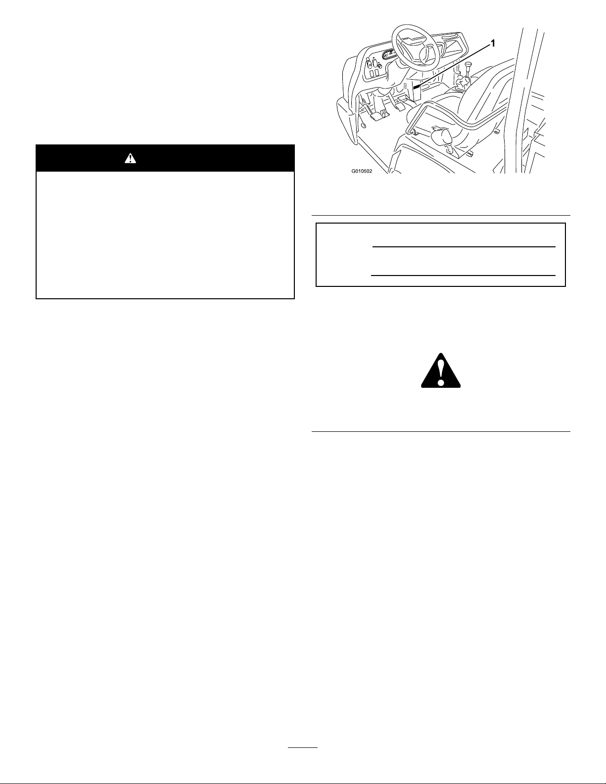
Figure1
1.Modelandserial-numberlocation
ModelNo.
SerialNo.
Thismanualidentiespotentialhazardsandhassafety
messagesidentiedbythesafety-alertsymbol(Figure2),
whichsignalsahazardthatmaycauseseriousinjuryordeath
ifyoudonotfollowtherecommendedprecautions.
Figure2
1.Safety-alertsymbol
Thismanualuses2wordstohighlightinformation.
Importantcallsattentiontospecialmechanicalinformation
andNoteemphasizesgeneralinformationworthyofspecial
attention.
Readthisinformationcarefullytolearnhowtooperateand
maintainyourproductproperlyandtoavoidinjuryand
productdamage.Youareresponsibleforoperatingthe
productproperlyandsafely.
YoumaycontactTorodirectlyatwww .Toro.comforproduct
andaccessoryinformation,helpndingadealer,ortoregister
yourproduct.
Wheneveryouneedservice,genuineT oroparts,oradditional
information,contactanAuthorizedServiceDealerorToro
CustomerServiceandhavethemodelandserialnumbersof
yourproductready.Figure1identiesthelocationofthe
modelandserialnumbersontheproduct.Writethenumbers
inthespaceprovided.
©2015—TheToro®Company
8111LyndaleAvenueSouth
Bloomington,MN55420
Contactusatwww.Toro.com.
2
PrintedintheUSA
AllRightsReserved
Page 3

Contents
Safety...........................................................................4
SafeOperatingPractices...........................................4
SoundPressure.......................................................7
Vibration................................................................7
SafetyandInstructionalDecals.................................8
Setup...........................................................................13
1InstallingtheSteeringWheel..................................13
2InstallingtheRollover-ProtectionSystem
(ROPS).............................................................13
3CheckingtheFluidLevels.....................................14
ProductOverview.........................................................15
Controls...............................................................15
Specications........................................................18
Attachments/Accessories........................................18
Operation....................................................................19
OperatingtheCargoBox.........................................19
CheckingtheEngine-OilLevel.................................20
RespondingtoaCheck-EngineLight........................21
AddingFuel...........................................................21
CheckingtheCoolantLevel.....................................22
CheckingtheTransaxle/Hydraulic-Fluid
Level.................................................................23
CheckingtheHighFlowHydraulic-Fluid
Level.................................................................24
CheckingtheFront-Differential-OilLevel..................25
CheckingtheTorqueoftheWheelNuts.....................25
CheckingtheTirePressure......................................25
CheckingtheBrake-FluidLevel................................25
StartingtheEngine.................................................26
DrivingtheMachine...............................................26
StoppingtheMachine.............................................27
ShuttingOfftheEngine..........................................27
BreakinginaNewMachine......................................27
CheckingtheSafety-InterlockSystem........................27
EnsuringPassengerSafety.......................................28
EnsuringProperSpeed...........................................28
EnsuringProperTurning.........................................28
EnsuringProperBraking.........................................28
PreventingTipOvers..............................................29
OperatingonHills..................................................29
LoadingandDumping............................................29
UsingtheDifferentialLock......................................30
Using4-WheelDrive..............................................30
TransportingtheMachine........................................31
TowingtheMachine...............................................31
TowingaTrailerwiththeMachine.............................31
UsingtheHydraulicControl....................................32
Maintenance.................................................................34
RecommendedMaintenanceSchedule(s)......................34
OperatinginAdverseConditions..............................35
PremaintenanceProcedures........................................36
UsingtheBedSupport............................................36
RemovingtheFullBed............................................37
InstallingtheFullBed.............................................37
RaisingtheMachine................................................38
RemovingtheHood...............................................39
InstallingtheHood.................................................39
Lubrication...............................................................40
GreasingtheBearingsandBushings..........................40
EngineMaintenance..................................................42
InspectingtheCarbonCanisterAirFilter...................42
ServicingtheAirCleaner.........................................42
ChangingtheEngineOilandFilter...........................43
ReplacingtheSparkPlugs........................................43
FuelSystemMaintenance...........................................44
ReplacingtheFuelFilter..........................................44
InspectingtheFuelLinesandConnections.................44
ElectricalSystemMaintenance....................................45
ServicingtheFuses.................................................45
JumpStartingtheMachine.......................................45
ServicingtheBattery...............................................46
DriveSystemMaintenance.........................................47
ChangingtheFront-DifferentialOil..........................47
InspectingtheConstant-VelocityBoot......................47
AdjustingtheShiftCables........................................47
AdjustingtheHigh–LowCable................................48
AdjustingDifferential-LockCable............................48
InspectingtheTires................................................48
CheckingtheFront-WheelAlignment.......................48
CoolingSystemMaintenance......................................49
RemovingDebrisfromtheCoolingSystem................49
ChangingtheEngineCoolant...................................50
BrakeMaintenance....................................................51
AdjustingtheParkingBrake.....................................51
AdjustingtheBrakePedal........................................51
BeltMaintenance......................................................52
AdjustingtheAlternatorBelt...................................52
ControlsSystemMaintenance.....................................53
AdjustingtheClutchPedal.......................................53
ConvertingtheSpeedometer....................................53
HydraulicSystemMaintenance....................................54
ChangingtheHydraulicFluidandCleaningthe
Strainer..............................................................54
ReplacingtheHydraulicFilter..................................54
ChangingtheHigh-FlowHydraulicFluidand
Filter.................................................................55
RaisingtheCargoBoxinanEmergency.....................55
Cleaning...................................................................57
WashingtheMachine..............................................57
Storage........................................................................57
3
Page 4

Safety
Improperuseormaintenancebytheoperatororownercan
resultininjury.Toreducethepotentialforinjury,comply
withthesesafetyinstructionsandalwayspayattentionto
thesafetyalertsymbol,whichmeansCaution,Warning,or
Danger—personalsafetyinstruction.Failuretocomplywith
theinstructionmayresultinpersonalinjuryordeath.
ThemachinemeetstherequirementsofSAEJ2258.
SafeOperatingPractices
Important:Thismachineisdesignedprimarilyasan
off-roadvehicleandisnotintendedforextensiveuse
onpublicroads.
Whenusingthemachineonpublicroads,followall
trafcregulationsanduseanyadditionalaccessories
thatmayberequiredbylaw,suchaslights,turn
signals,slow-movingvehicle(SMV)signs,andothers
asrequired.
Thismachinewasdesignedandtestedtooffersafeservice
whenoperatedandmaintainedproperly.Althoughhazard
controlandaccidentpreventionaredependentuponthe
designandcongurationofthemachine,thesefactorsare
alsodependentupontheawareness,concern,andproper
trainingoftheoperator,maintenance,andstorageofthe
machine.Improperuseormaintenanceofthemachinecan
resultininjuryordeath.
Thismachinehasadifferentfeelthanwhatdriversexperience
withpassengercarsortrucks.Sotaketimetobecomefamiliar
withyourmachine.
Notalloftheattachmentsthatadapttothemachine
arecoveredinthismanual.SeethespecicOperator’s
Manualprovidedwitheachattachmentforadditionalsafety
instructions.
Toreducethepotentialforinjuryordeath,complywith
thefollowingsafetyinstructions:
Supervisor’sResponsibilities
•Makesureoperatorsarethoroughlytrainedandfamiliar
withtheOperator’ sManualandalllabelsonthevehicle.
•Besuretoestablishyourownspecialproceduresand
workrulesforunusualoperatingconditions(e.g.,slopes
toosteepforthesafeoperationofthemachine).
BeforeOperating
•Thismachineisdesignedtocarryonlyyou,the
operator,andonepassengerintheseatprovidedbythe
manufacturer.Nevercarryanyotherpassengersonthe
vehicle.
•Becomefamiliarwiththecontrolsandknowhowtostop
theenginequickly.
•Neveroperatethemachinewhentired,ill,orunderthe
inuenceofdrugsoralcohol.
•Alwayswearsubstantialshoes.Donotwearloose-tting
clothing,tiebacklonghair,anddonotwearjewelry.
•Wearingsafetyglasses,safetyshoes,andlongpantsare
requiredbysomelocalsafetyandinsuranceregulations.
•Neverallowchildrentooperatethemachine.Never
allowadultstooperateitwithoutproperinstructions.
Onlytrainedandauthorizedpersonsshouldoperatethis
machine.Makesurethatalloperatorsarephysicallyand
mentallycapableofoperatingthemachine.
•Alwaysbeawareofwherebystandersare.
•Keepallshields,safetydevicesanddecalsinplace.Ifa
shield,safetydeviceordecalismalfunctioning,illegible,
ordamaged,repairorreplaceitbeforeoperatingthe
machine.
•Avoiddrivingwhenitisdark,especiallyinunfamiliar
areas.Ifyoumustdrivewhenitisdark,besuretodrive
cautiously,usetheheadlights.
•Beforeoperatingthevehicle,alwayscheckallpartsofthe
vehicleandanyattachments.Ifsomethingiswrong,stop
usingvehicle.Makesurethattheproblemiscorrected
beforevehicleorattachmentisoperatedagain.
•Operatethemachineonlyoutdoorsorinawell-ventilated
area.
SafeHandlingofFuels
•Toavoidpersonalinjuryorpropertydamage,useextreme
careinhandlingfuel.Fuelisextremelyammableandthe
vaporsareexplosive.
•Extinguishallcigarettes,cigars,pipes,andothersources
ofignition.
•Useonlyanapprovednonmetal,portablefuelcontainer.
•Staticelectricdischargecanignitefuelvaporsinafuel
containerthatisnotgrounded.Neverllcontainers
insideavehicleoronatruckortrailerbedwithaplastic
liner.Removethefuelcontainerfromthebedofthe
machineandplaceitonthegroundandawayfromthe
vehiclebeforelling.
•Keepthenozzleincontactwiththecontainerwhilelling
thefuelcontainer.Removeequipmentfrombedofthe
machinebeforefuelingit.Donotuseanozzle-lock-open
device.
•Neverremovefuelcaporaddfuelwiththeengine
running.
•Allowenginetocoolbeforerefueling.
•Neverrefuelthemachineindoors.
•Neverstorethemachineorfuelcontainerwherethereis
anopename,spark,orpilotlight,suchasonawater
heateroronotherappliances.
•Removeequipmentfromthetruckortrailerandrefuelit
ontheground.Ifthisisnotpossible,thenrefuelsuch
equipmentwithaportablecontainerratherthanfroma
fuel-dispensernozzle.
4
Page 5

•Iffuelisspilledonclothing,changeclothingimmediately.
•Neveroverllthefueltank.Replacethefuelcapand
tightenitsecurely.
Operation
•Theoperatorandpassengermustuseseatbeltsand
remainseatedwheneverthemachineisinmotion.Keep
bothhandsonthesteeringwheel,wheneverpossible,and
thepassengershouldusethehandholdsprovided.Keep
yourarmsandlegswithinthevehiclebodyatalltimes.
Nevercarrypassengersintheboxoronattachments.
Remember,yourpassengermaynotbeexpectingyouto
brakeorturn,andmaynotbeready.
•Neveroverloadyourvehicle.Thenameplate(located
underthemiddleofthedash)showstheloadlimitsfor
thevehicle.Neveroverllattachmentsorexceedthe
machinemaximumgross-vehicleweight(GVW).
•Whenstartingtheengine:
–Sitontheoperator’sseatandensurethattheparking
brakeisengaged.
–DisengagethePTO(ifsoequipped)andreturnthe
hand-throttlelevertotheOFFposition(ifequipped).
–Makesurethatthehydraulic-liftleverisinthecenter
position.
–MovetheshiftlevertotheNEUTRALpositionand
presstheclutchpedal.
–Keepyourfootofftheacceleratorpedal.
–TurnignitionswitchtotheONposition.
–TurntheignitionkeytotheSTARTposition.
•Failuretooperatemachinesafelymayresultinan
accident,tippingoverthemachine,and/orseriousinjury
ordeath.Topreventtippingorlossofcontrol,takethe
followingprecautions:
–Useextremecaution,reduceyourspeed,andmaintain
asafedistancearoundsandtraps,ditches,creeks,
ramps,anyunfamiliarareas,orotherhazards.
–Watchforholesorotherhiddenhazards.
–Usecautionwhenoperatingthemachineonasteep
slope.Normally,travelstraightupanddownslopes.
Reduceyourspeedwhenmakingsharpturnsor
whenturningonhillsides.Avoidturningonhillsides
wheneverpossible.
–Useextracautionwhenoperatingthevehicleon
wetsurfaces,athigherspeeds,orwithafullload.
Stoppingtimewillincreasewithafullload.Shiftinto
alowergearbeforestartingupordownahill.
–Whenloadingthebed,distributetheloadevenly.
Useextracautioniftheloadexceedsthedimensions
ofthemachine/bed.Operatethevehiclewithextra
cautionwhenhandlingoff-centerloadsthatcannot
becentered.Keeploadsbalancedandsecureto
preventthemfromshifting.
–Avoidsuddenstopsandstarts.Donotgofrom
reversetoforwardorforwardtoreversewithoutrst
comingtoacompletestop.
–Donotattemptsharpturnsorabruptmaneuversor
otherunsafedrivingactionsthatmaycausealossof
machinecontrol.
–Whendumping,donotletanyonestandbehindthe
machine,anddonotdumptheloadonanyone’sfeet.
Releasethetailgatelatchesfromthesideofbox,not
frombehind.
–Keepallbystandersaway .Beforebackingup,lookto
therearandensurethatnooneisbehindthemachine.
Backupslowly.
–Watchoutfortrafcwhennearorcrossingroads.
Alwaysyieldtherightofwaytopedestriansandother
machines.Thismachineisnotdesignedforuseon
streetsorhighways.Alwayssignalyourturnsorstop
earlyenoughsootherpersonsknowwhatyouplanto
do.Obeyalltrafcrulesandregulations.
–Neveroperatethemachineinornearanareawhere
thereisdustorfumesintheairwhichareexplosive.
Theelectricalandexhaustsystemsofthemachinecan
producesparkscapableofignitingexplosivematerials.
–Alwayswatchoutforandavoidlowoverhangssuch
astreelimbs,doorjambs,overheadwalkways,etc.
Makesurethereisenoughroomoverheadtoeasily
clearthemachineandyourhead.
–Ifyouareeverunsureaboutsafeoperation,stop
work,andaskyoursupervisor.
•Donottouchtheengine,transaxle,radiator,mufer,or
mufermanifoldwhiletheengineisrunningorsoonafter
ithasstoppedbecausetheseareasmaybehotenough
tocauseburns.
•Ifthemachineevervibratesabnormally,stopimmediately,
shuttheengineoff,waitforallmotiontostop,and
inspectfordamage.Repairalldamagebeforeresuming
operation.
•Beforegettingofftheseat:
1.Stopthemachine.
2.Settheparkingbrake.
3.TurntheignitionkeytotheOFFposition.
4.Removetheignitionkey .
Note:Ifthemachineisonanincline,blockthe
wheelsaftergettingoffthemachine.
•Lightningcancausesevereinjuryordeath.Iflightning
isseenorthunderisheardinthearea,donotoperate
themachine;seekshelter.
Braking
•Slowdownbeforeyouapproachanobstacle.Thisgives
youextratimetostoporturnaway.Hittinganobstacle
5
Page 6

caninjureyouandyourpassenger.Inaddition,itcan
damagethemachineanditscontents.
•GrossVehicleWeight(GVW)hasamajorimpactonyour
abilitytostopand/orturn.Heavyloadsandattachments
makethemachinehardertostoporturn.Theheavierthe
load,thelongerittakestostop.
•Decreasethespeedofthemachineifthecargoboxhas
beenremovedandthereisnoattachmentinstalledon
themachine.Thebrakingcharacteristicschangeandfast
stopsmaycausetherearwheelstolockup,whichwill
affectthecontrolofthemachine.
•Turfandpavementaremuchmoreslipperywhentheyare
wet.Itcantake2to4timeslongertostopthemachine
onwetsurfacesasondrysurfaces.Ifyoudrivethrough
deep-standingwaterandgetthebrakeswet,theywill
notworkwelluntiltheyaredry.Afterdrivingthrough
water,youshouldtestthebrakestomakesuretheywork
properly.Iftheydonot,driveslowlyonalevelground
whileputtinglightpressureonthebrakepedal.Thiswill
drythebrakesout.
OperatingonHills
WARNING
Operatingthemachineonahillmaycausetipping
orrollingofthemachine,ortheenginemaystall
andyoucouldloseheadwayonthehill.Thiscould
resultinpersonalinjury.
•Donotoperatethemachineonexcessivelysteep
slopes.
theloadhasahighcenterofgravity.Securetheloadto
thecargoboxofthemachinetopreventtheloadfrom
shifting.Takeextracarewhenhaulingloadsthatshift
easily(liquid,rock,sand,etc.).
•Avoidstoppingonhills,especiallywithaload.Stopping
whilegoingdownahillwilltakelongerthanstoppingon
levelground.Ifyoumuststopthemachine,avoidsudden
speedchanges,whichmayinitiatetippingorrollingof
themachine.Donotslamonthebrakeswhenrolling
backward,asthismaycausethemachinetooverturn.
•Ifyouwillbeusingthemachineonhillyterrain,youcan
installtheoptionalROPSKit.
OperatingonRoughTerrain
Reducethegroundspeedofthemachineandloadcarriedin
themachinewhenoperatingonroughterrain,unevenground,
andnearcurbs,holes,andothersuddenchangesinterrain.
Loadsmayshift,causingthemachinetobecomeunstable.
WARNING
Suddenchangesinterrainmaycauseabrupt
steeringwheelmovement,possiblyresultingin
handandarminjuries.
•Reduceyourspeedwhenoperatingonrough
terrainandnearcurbs.
•Gripthesteeringwheellooselyaroundthe
perimeterkeepingthumbsupandoutoftheway
ofthesteeringwheelspokes.
•Donotacceleratequicklyorslamthebrakes
whenbackingdownahill,especiallywithaload.
•Iftheenginestallsoryouloseheadwayona
hill,slowlybackstraightdownthehill.Never
attempttoturnthemachinearound.
•Operatethemachineslowlyonahillanduse
caution.
•Avoidturningonahill.
•Reduceyourloadandthespeedofthemachine.
•Avoidstoppingonhills,especiallywithaload.
Taketheseprecautionswhenoperatingthemachineonahill:
•Slowthemachinedownbeforestartingupordownahill.
•Iftheenginestallsoryoubegintolosemomentumwhile
climbingahill,graduallyapplythebrakesandslowlyback
themachinestraightdownthehill.
•Turningwhiletravelingupordownhillscanbedangerous.
Ifyouhavetoturnwhileonahill,doitslowlyand
cautiously.Nevermakesharporfastturns.
•Heavyloadsaffectstability.Reducetheweightofthe
loadandyourgroundspeedwhenoperatingonhillsorif
LoadingandDumping
Theweightandpositionofcargoandpassengercanaffect
thestabilityandhandlingofthemachine.Beawareofthe
followingconditiontoavoidlosingcontrolofthemachine
ortippingitover:
•Donotexceedtheratedweightcapacityofthemachine
whenoperatingitwithaloadinthecargobox,when
towingatrailer,orboth;refertoSpecications(page18).
•Usecautionwhenoperatingthemachineonahillsideor
onroughterrain,particularlywithaloadinthecargobox
orwhentowingatrailerorboth.
•Beawarethatthestabilityandcontrolofthemachine
arereducedwhentheloadinthecargoboxispoorly
distributed.
•Carryingoversizedloadsinthecargoboxchangesthe
stabilityofthemachine.
•Thesteering,braking,andstabilityofthemachineare
affectedwhencarryingaloadwheretheweightofthe
materialcannotbeboundtothemachinesuchasthe
liquidinalargetank.
6
Page 7

WARNING
Theweightoftheboxmaybeheavy.Handsor
otherbodypartscouldbecrushed.
–Keephandsandotherbodypartsclearwhen
loweringthebox.
–Donotdumpmaterialsonbystanders.
•Neverdumpaloadedcargoboxwhilethemachineis
sidewaysonahill.Thechangeinweightdistributionmay
causethemachinetooverturn.
•Whenoperatingwithaheavyloadinthecargobox,
reduceyourspeedandallowforsufcientbraking
distance.Donotsuddenlyapplythebrakes.Useextra
cautiononslopes.
•Beawarethatheavyloadsincreaseyourstoppingdistance
andreduceyourabilitytoturnquicklywithouttipping
over.
•Therearcargospaceisintendedforloadcarrying
purposesonly,notforpassengers.
•Neveroverloadyourmachine.Thenameplate(located
underthemiddleofthedash)showstheloadlimitsfor
themachine.Neveroverllattachmentsorexceedthe
machinemaximumgrossvehicleweight(GVW).
Maintenance
Placetheremotehydraulicsleverintheoatposition.
Iftheboxmustbeinraisedposition,secureitwiththe
safetysupport.
•Tomakesurethattheentiremachineisingoodcondition,
keepallnuts,bolts,andscrewsproperlytightened.
•Toreducethepotentialrehazard,keeptheenginearea
freeofexcessivegrease,grass,leaves,andaccumulation
ofdirt.
•Iftheenginemustberunningtoperformamaintenance
adjustment,keephands,feet,clothing,andanypartsof
thebodyawayfromtheengineandanymovingparts.
Keepeveryoneaway.
•Donotoverspeedtheenginebychangingthegovernor
settings.Themaximumenginespeedis3,650rpm.To
ensuresafetyandaccuracy,haveanAuthorizedToro
Distributorcheckthemaximumenginespeedwitha
tachometer.
•Ifmajorrepairsareeverneededorassistanceisrequired,
contactanAuthorizedToroDistributor.
•Tobesureofoptimumperformanceandsafety,
alwayspurchasegenuineTororeplacementpartsand
accessories.Replacementpartsandaccessoriesmadeby
othermanufacturerscouldbedangerous.Alteringthis
vehicleinanymannermayaffectthevehicle’soperation,
performance,durabilityoritsusemayresultininjuryor
death.SuchusecouldvoidtheproductwarrantyofThe
Toro®Company.
WARNING
Hydraulicuidescapingunderpressurecanhave
sufcientforcetopenetrateskinanddoserious
damage.Ifuidisinjectedintotheskin,itmustbe
surgicallyremovedwithinafewhoursbyadoctor
familiarwiththisformofinjuryorgangrenemay
result.
Keepyourbodyandhandsawayfrompinholeleaks
ornozzlesthatejecthydraulicuidunderhigh
pressure.Usepaperorcardboard,notyourhands,
tosearchforleaks.
•Beforeservicingormakingadjustmentstothemachine,
shutofftheengine,settheparkingbrake,andremove
thekeyfromtheignitiontopreventaccidentalstarting
oftheengine.
•Neverworkunderaraisedbedwithoutplacingthebed
safetysupportonthefullyextendedcylinderrod.
•Makesurethatallhydraulic-lineconnectorsaretight,and
thatallhydraulichosesandlinesareingoodcondition
beforeapplyingpressuretothesystem.
•Beforedisconnectingorperforminganyworkonthe
hydraulicsystem,allpressureinthesystemmustbe
relievedbystoppingtheengine,cyclingthedumpvalve
fromraisetolowerand/orloweringboxandattachments.
SoundPressure
Thisunithasasoundpressurelevelattheoperator’searof75
dBA,whichincludesanUncertaintyValue(K)of1dBA.
Thesoundpressurelevelwasdeterminedaccordingtothe
proceduresoutlinedinENISO11201.
Vibration
Hand-Arm
•Measuredvibrationlevelforrighthand=0.34m/s
•Measuredvibrationlevelforlefthand=0.43m/s
•UncertaintyValue(K)=0.5m/s
Measuredvaluesweredeterminedaccordingtotheprocedures
outlinedinEN1032.
2
WholeBody
•Measuredvibrationlevel=0.33m/s
•UncertaintyValue(K)=0.5m/s
Measuredvaluesweredeterminedaccordingtotheprocedures
outlinedinEN1032.
2
2
2
2
7
Page 8
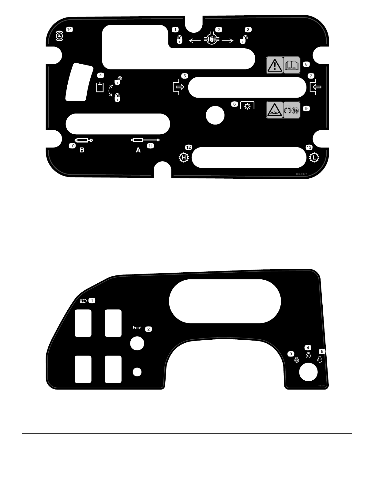
SafetyandInstructionalDecals
Safetydecalsandinstructionsareeasilyvisibletotheoperatorandarelocatednearanyareaofpotential
danger.Replaceanydecalthatisdamagedorlost.
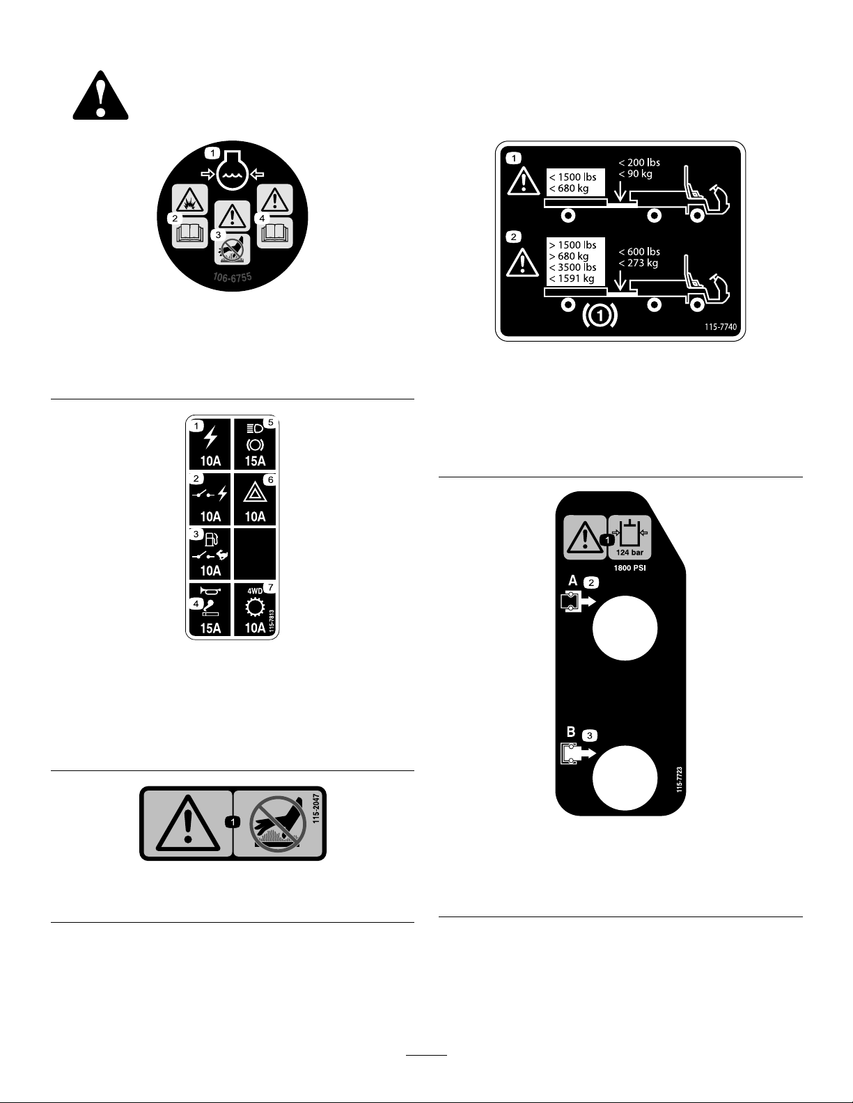
106-6755
1.Enginecoolantunder
pressure.
2.Explosionhazard—read
theOperator'sManual.
3.Warning—donottouchthe
hotsurface.
4.Warning—readthe
Operator'sManual.
115-7813
1.Poweroutlet—10A5.Lights,brake—15A
2.Switchedpower—10A
3.Fuelpump,supervisor
switch—10A
4.Horn,powerpoint—15A
6.Hazard—10A
7.4WD,Transmission—10A
115-7740
1.Warning—maximumtrailerweightis1,500lb(680kg),
maximumtongueweightis200lb(90kg).
2.Warning—trailerbrakesarerequiredwhentowinggreater
than1,500lb(680kg),maximumtrailerweightwithtrailer
brakesis3,500lb(1,591kg),maximumtongueweightwith
trailerbrakesis600lb(273kg).
1.Warning—donottouchthehotsurface.
115-7723
1.Warning—thehydraulicoilpressureis124bar(1,800psi).
115-2047
2.CouplerA
3.CouplerB
8
Page 9
115-2282
1.Warning—readtheOperator'sManual.
2.Warning—stayawayfrommovingparts,keepallguardsandshieldsinplace.
3.Crushing/dismembermenthazardofbystanders—keepbystandersasafedistancefromthevehicle,donotcarrypassengersin
thecargobed,keeparmsandlegsinsideofthevehicleatalltimes,anduseseatbeltsandhandholds.
121-9776
1.Warning—readtheOperator’sManualandreceiveproper
trainingbeforeoperatingthemachine.
2.Warning—wearhearingprotection.5.Tippinghazard—taketurnsslowly;driveslowlyupandacross
3.Firehazard—stoptheenginebeforerefuelingthemachine.
106-2355
1.Slow
2.Fast
3.Transmission—thirdhigh;
nofastspeed
4.Warning—engagetheparkingbrake,stoptheengine,and
removethekeyfromtheignitionbeforewalkingawayfrom
themachine.
cliffs;withnoload,donotexceed32kph(20mph);while
carryingaloadorwhendrivingonuneventerrain,driveslowly.
106-2353
1.Electricalpowerpoint
115-7741
1.ReadtheOperator’sManualbeforeservicingtransmission
uid.
105-4215
1.Warning—avoidpinchpoints.
9
Page 10
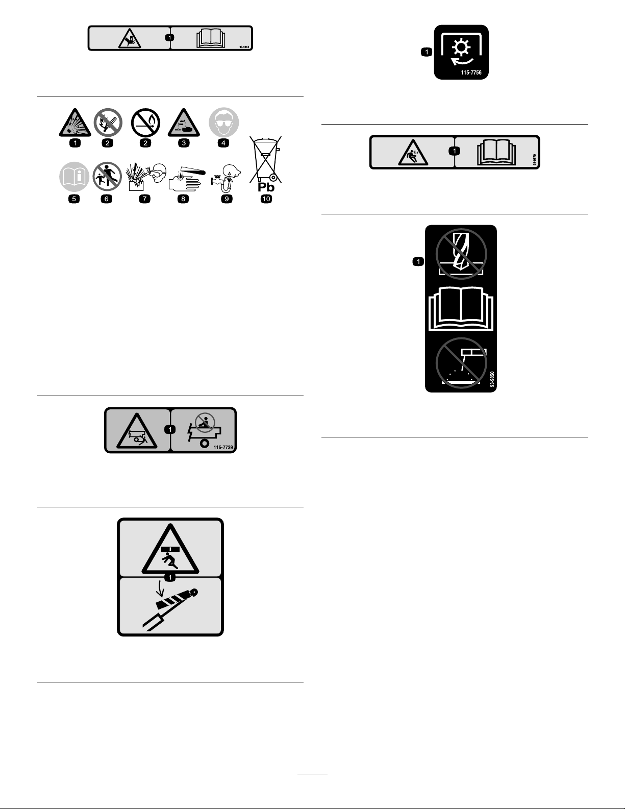
93–9868
93-9899
1.Crushinghazardofhand—readtheOperator’sManual.
BatterySymbols
Someorallofthesesymbolsareonyourbattery .
1.Explosionhazard
2.Nore,opename,or
smoking.
3.Causticliquid/chemical
burnhazard
4.Weareyeprotection9.Flusheyesimmediately
5.ReadtheOperator's
Manual.
6.Keepbystandersasafe
distancefromthebattery.
7.Weareyeprotection;
explosivegasescan
causeblindnessandother
injuries
8.Batteryacidcancause
blindnessorsevereburns.
withwaterandgetmedical
helpfast.
10.Containslead;donot
discard.
115-7756
1.High-owhydraulics—engaged
93-9879
1.Storedenergyhazard—readtheOperator'sManual.
115-7739
1.Falling,crushinghazard,bystanders—noriderson
machine.
93-9899
1.Crushinghazard—installthecylinderlock.
93-9850
1.Donotrepairorrevise—readtheOperator'sManual.
10
Page 11
106-2377
1.Locked
2.Differentiallock9.Entanglementhazard,shaft—keepbystander'sasafe
3.Unlocked10.Retracthydraulics
4.Hydrauliclock11.Extendhydraulics
5.Engage12.Transmission—highspeed
6.Powertakeoff(PTO)
7.Disengage14.Parkingbrake
8.Warning—readtheOperator'sManual.
distancefromthevehicle.
13.Transmission—lowspeed
1.Headlights4.Engine—run
2.Horn5.Engine—start
3.Engine—stop
115-2281
11
Page 12
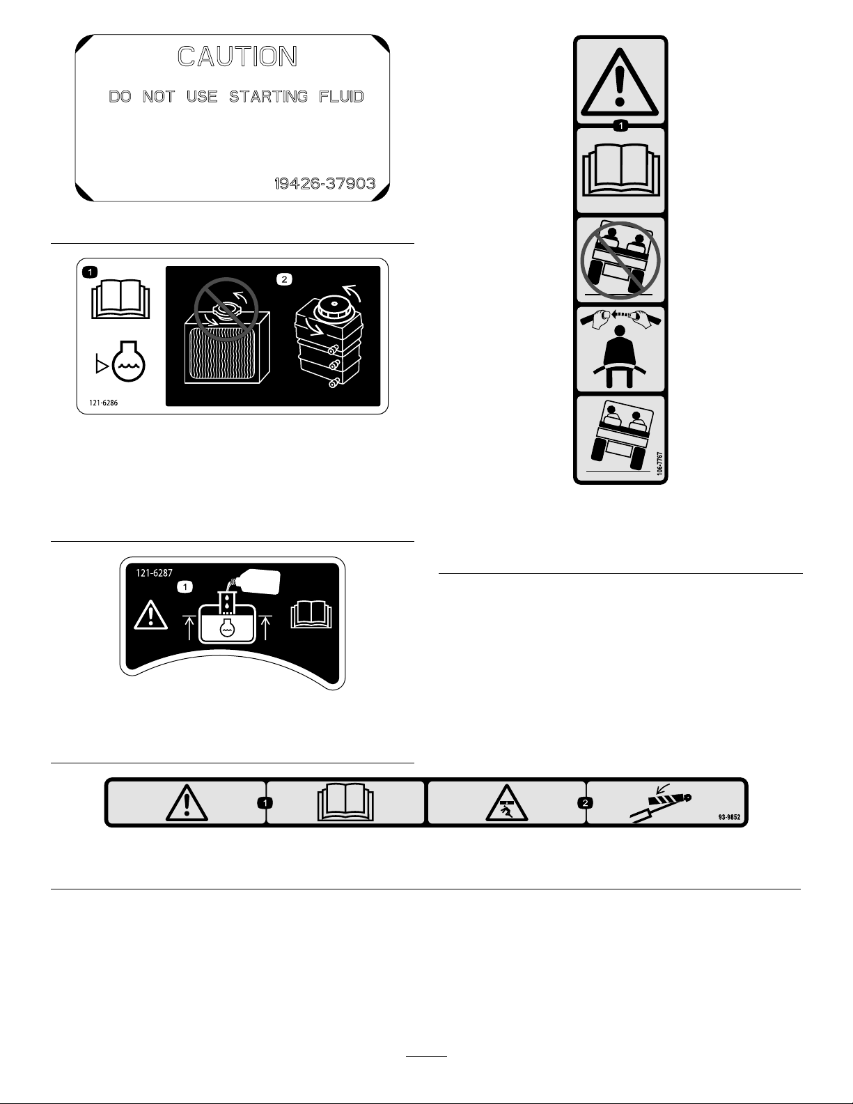
110–0806
121-6286
1.Thecoolantlevelmust
becheckeddailybefore
use.ReadtheOperator's
Manualbeforechecking
thecoolantlevel.
2.Donotopenoraddcoolant
totheradiator;doingso
willintroduceairinto
thesystemandresultin
enginedamage.Onlyadd
coolanttothereservoir.
121-6287
1.Fillthereservoirwithenginecoolanttothebottomofthe
llerneck.
106-7767
1.Warning—readtheOperator'sManual;avoidtippingthe
machine;weartheseatbelt;leanawayfromthedirection
themachineistipping.
93-9852
1.Warning—readtheOperator’sManual.2.Crushinghazard—installthecylinderlock.
12
Page 13
Setup
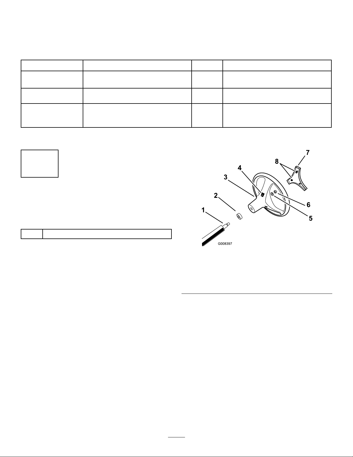
LooseParts
Usethechartbelowtoverifythatallpartshavebeenshipped.
ProcedureDescription
1
2
3
Note:Determinetheleftandrightsidesofthemachinefromthenormaloperatingposition.
Steeringwheel
ROPSframe
Bolt(1/2inch)
Nopartsrequired
Qty.
1
InstallingtheSteeringWheel
TCModelsOnly
Partsneededforthisprocedure:
Use
1
1
6
–
Installthesteeringwheel(TCmodels
only).
MounttheRollover-ProtectionSystem
(ROPS).
Checktheengineoil,the
transaxle/hydraulicuid,andthe
brake-uidlevels.
1
Steeringwheel
Procedure
1.Releasethetabsonthebackofthesteeringwheelthat
holdthecentercoverinplace,andremovethecover
fromthehubofthesteeringwheel.
2.Removethelocknutandwasherfromthesteeringshaft.
3.Slidethesteeringwheelandwasherontotheshaft.
Note:Alignthesteeringwheelontheshaftsothat
thecrossbeamishorizontalwhenthetiresarepointed
straightaheadandthethickerspokeofthesteering
wheelisdownward.
Note:Thedustcoverispositionedontothesteering
shaftatthefactory.
4.Securethesteeringwheeltotheshaftwiththelocknut
andtorquethelocknutto24to29N∙m(18to22ft-lb)
asshowninFigure3.
Figure3
1.Steeringshaft
2.Dustcover6.Locknut
3.Steeringwheel7.Cover
4.Tabslotsinwheel8.Tabsincover
5.Alignthetabsofthecoverwiththeslotsinthesteering
wheel,andsnapthecoverontothesteering-wheelhub
(Figure3).
5.Washer
13
Page 14
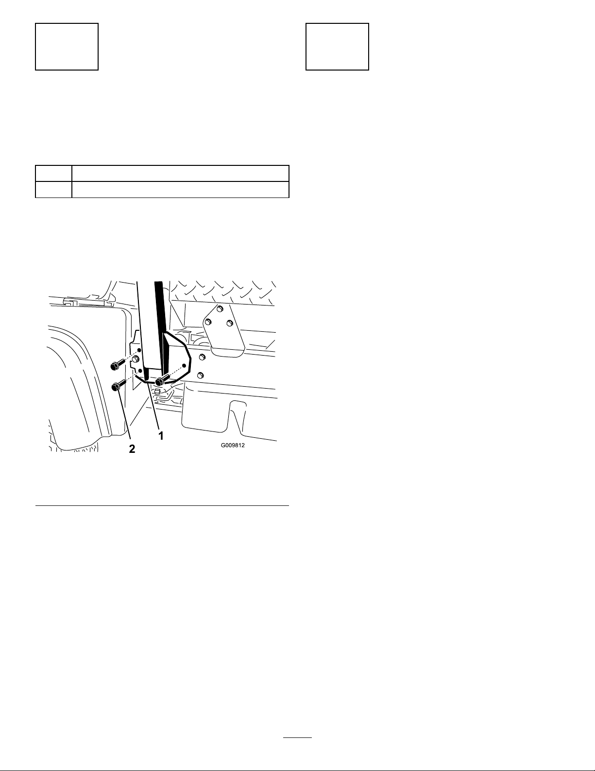
2
3
Installingthe
Rollover-ProtectionSystem
(ROPS)
Partsneededforthisprocedure:
1
ROPSframe
6
Bolt(1/2inch)
Procedure
1.AligneachsideoftheROPSwiththemountingholes
intheframeateachsideofthevehicleasshownin
Figure4.
CheckingtheFluidLevels
NoPartsRequired
Procedure
1.Checktheengine-oillevelbeforeandaftertheengine
isrststarted;refertoCheckingtheEngine-OilLevel
(page20).
2.Checkthetransaxle/hydraulic-uidlevelbefore
theengineisrststarted;refertoCheckingthe
Transaxle/Hydraulic-FluidLevel(page23).
3.Checkthebrake-uidlevelbeforetheengineisrst
started;refertoCheckingtheBrake-FluidLevel(page
25).
4.Checkthecoolantlevel;refertoCheckingtheCoolant
Level(page22).
Figure4
1.ROPS-mountingbracket2.Flangedbolts(1/2x1-1/4
2.SecureeachsideoftheROPStoframewith3anged
bolts(1/2x1-1/4inches),andtightentheboltsto115
N∙m(85ft-lb).
inches)
14
Page 15
ProductOverview
Controls
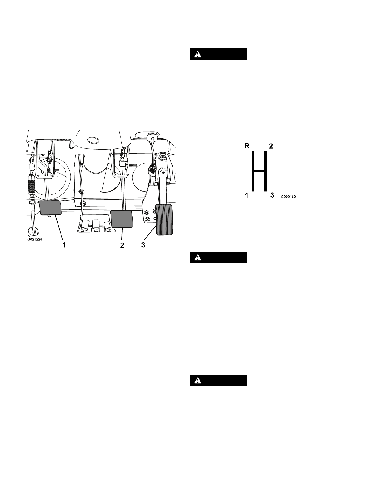
BrakePedal
Thebrakepedal(Figure5)isusedtoapplytheservicebrakes
tostoporslowthemachine.
Note:Determinetheleftandrightsidesofthemachine
fromthenormaloperatingposition.
AcceleratorPedal
Theacceleratorpedal(Figure5)givestheoperatortheability
tovarytheengineandgroundspeedofthemachinewhen
thetransmissionisingear.Pressingthepedalincreasesthe
enginerpmandgroundspeed.Releasingthepedaldecreases
theenginerpmandgroundspeedofthemachine.
CAUTION
Wornormaladjustedbrakesmayresultinpersonal
injury.Ifthebrakepedaltravelstowithin3.8cm
(1-1/2inches)ofthemachineoorboard,the
brakesmustbeadjustedorrepaired.
Gear-ShiftLever
Fullypresstheclutchpedalandmovetheshiftlever(Figure
6)intothedesiredgearselection.Adiagramoftheshift
patternisshownbelow.
Figure6
Important:Donotshiftthetransaxletothereverseor
forwardgearunlessthevehicleisstandingstill.Damage
tothetransaxlemayoccur.
Figure5
1.Clutchpedal
2.Brakepedal
3.Acceleratorpedal
ClutchPedal
Theclutchpedal(Figure5)mustbefullypressedtodisengage
theclutchwhenstartingtheengineorshiftingtransmission
gears.Releasethepedalsmoothlywhenthetransmissionis
ingeartopreventunnecessarywearonthetransmissionand
otherrelatedparts.
Important:Donotridetheclutchpedalduring
operation.Theclutchpedalmustbefullyoutorthe
clutchwillslipcausingheatandwear.Neverhold
themachinestoppedonahillusingtheclutchpedal.
Damagetotheclutchmayoccur.
CAUTION
Downshiftingfromtoohighaspeedcancausethe
rearwheelstoskidresultinginlossofmachine
controlaswellasclutchand/ortransmission
damage.
DifferentialLock
Thedifferentiallockallowstherearaxletolockforincreased
traction.Youcanengagethedifferentiallockwhenthe
machineisinmotion(Figure7).Movetheleverforwardand
totherighttoengagethelock.
Note:Machinemotionplusaslightturnisrequiredto
engageordisengagethedifferentiallock.
CAUTION
Turningwiththedifferentiallockoncanresult
inlossofmachinecontrol.Donotoperatewith
differentiallockonwhenmakingsharpturnsorat
highspeeds;refertoAdjustingDifferential-Lock
Cable(page48).
15
Page 16
Figure7
1.Gear-shiftlever4.Hydraulic-liftlock
2.Parkingbrake
3.Hydraulic-bedlift6.High–lowrangeshifter
5.Differentiallock
•Shiftonlyonlevelground.
•Presstheclutchpedalfully.
•MovetheleverfullyforwardforHighandfullyrearward
forLow .
Highisforhigherspeeddrivingonlevel,drysurfaceswith
lightloads.
Lowisforlow-speeddriving.Usethisrangewhengreater
thannormalpowerorcontrolisrequired.Forexample,
steepgrades,difcultterrain,heavyloads,slowspeedbut
high-enginespeed(spraying).
Important:ThereisalocationbetweenHighandLow
inwhichthetransaxleisinneitherrange.Donotuse
thispositionasaneutralpositionbecausethevehicle
couldmoveunexpectedlyiftheHigh–Lowshifteris
bumpedandthegear-shiftleverisingear.
ParkingBrake
Whenevertheengineisshutoff,settheparkingbrake(Figure
7)inordertopreventthemachinefromaccidentallymoving.
•Tosettheparkingbrake,pullbackonthelever.
•Torelease,pushtheleverforward.
Note:Releasetheparkingbrakebeforemovingthe
machine.
Ifyouparkthemachineonasteepgrade,settheparking
brake,shiftthetransmissionintorstgearonauphillgrade
orreversegearonadownhillgrade,andplacechocksatthe
downhillsideofthewheels.
HydraulicLift
Thehydraulicliftraisesandlowersthebed.Moveitrearward
toraisethebed,andforwardtolowerit(Figure7).
Important:Whenloweringthebed,holdtheleverin
theforwardpositionfor1or2secondsafterthebed
contactstheframetosecureitintheloweredposition.
Donotholdthehydraulicliftineithertheraiseorlower
position,formorethan5seconds,oncethecylinders
havereachedtheendoftheirtravel.
Hydraulic-LiftLock
Thehydraulic-liftlocklockstheliftlever,sothehydraulic
cylindersdonotoperatewhenthemachineisnotequipped
withabed(Figure7).ItalsolockstheliftleverintheON
positionwhenusingthehydraulicsforattachments.
IgnitionSwitch
Usetheignitionswitch(Figure8)tostartandshutoffthe
engine.Ithas3positions:OFF,ON,andSTART.Rotatethe
keyclockwisetotheSTARTpositiontoengagethestarter
motor.Releasethekeywhentheenginestarts.Thekeywill
moveautomaticallytotheONposition.Toshuttheengine
off,rotatethekeycounterclockwisetotheOFFposition.
Figure8
1.Lightswitch8.Fuelgauge
2.High-ow-hydraulics
switch(TCmodelsonly)
3.Horn(TCmodelsonly)
4.Tachometer
5.Hourmeter
6.Speedometer13.Glow-plugindicator
7.Coolant-temperature
gaugeandlight
9.Ignitionswitch
10.Powerpoint
11.Supervisorswitch
12.Oil-pressure-warninglight
14.Chargeindicator
High–LowRangeShifter
Thehigh–lowrangeshifteradds3additionalspeedsfor
precisespeedcontrol(Figure7).
•Themachinemustbecompletelystoppedbeforeshifting
betweentheHighandLowrange.
16
Page 17
HourMeter
Thehourmeterindicatesthetotalhoursofmachine
operation.Thehourmeter(Figure8)startstofunction
wheneverthekeyswitchisrotatedtotheONpositionorif
theengineisrunning.
Speed-LimiterSwitch
Checktheoperationofwarninglightsasfollows:
•Applytheparkingbrake.
•TurntheignitionkeytotheON/PREHEATposition,but
donotstarttheengine.Thecoolanttemperature,charge
indicator,andoil-pressurelightsshouldglow.Ifanylight
doesnotfunction,eitherabulbisburnedoutorthereisa
malfunctioninthesystemwhichmustberepaired.
Movethespeed-limiterswitch(Figure8)totheSLOWposition
andremovethekey.Theswitchlimitstheengineto2,200
rpmwhenthemachineisinthirdgearintheHighrange,
whichlimitsthetopspeedto21km/h(13mph).
LightSwitch
Pushthelightswitch(Figure8)totoggletheheadlightson
oroff.
Oil-Pressure-WarningLight
Theoil-pressure-warninglightglows(Figure8)ifthe
engine-oilpressuredropsbelowasafelevelwhiletheengine
isrunning.Ifthelightickersorremainson,stopthevehicle,
turnofftheengine,andchecktheoillevel.Iftheoillevelis
low,butaddingoildoesnotcausethelighttogooutwhen
theengineisrestarted,turntheengineoffimmediatelyand
contactyourlocalTorodistributorforassistance.
Checktheoperationofwarninglightsasfollows:
1.Applytheparkingbrake.
2.TurntheignitionkeytotheON/PREHEATposition,
butdonotstarttheengine.
Note:Theoil-pressurelightshouldglowred.Ifthe
lightdoesnotfunction,eitherabulbisburnedoutor
thereisamalfunctioninthesystemwhichmustbe
repaired.
FuelGauge
Thefuelgaugeshowstheamountoffuelinthetank.It
operatesonlywhenignitionswitchisintheONposition
(Figure8).Redindicateslowfuellevelandblinkingred
indicatesnearempty.
High-Flow-HydraulicsSwitch
TCModelsOnly
Turnontheswitchtoactivatethehigh-owhydraulics
(Figure8).
HornButton
TCModelsOnly
Pressingthehornbuttonactivatesthehorn(Figure8).
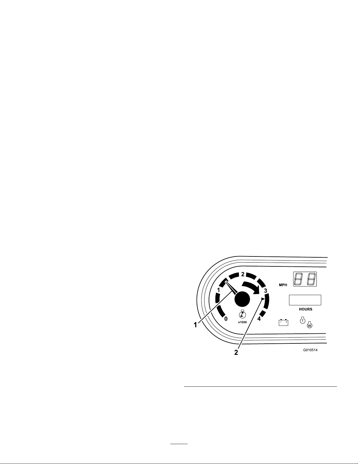
Tachometer
Registersthespeedoftheengine(Figure8andFigure9).The
whitetriangleindicates540rpmforPTOoperation(Figure9).
Note:Ifenginewasjustturnedoff,itmaytake1to
2minutesforthelighttocomeon.
Coolant-TemperatureGaugeandLight
Registersthecoolanttemperatureintheengine.Operates
onlywhentheignitionswitchisinONposition(Figure8).
Note:Theindicatorlightilluminatesblinkingredifthe
engineoverheats.
ChargeIndicator
Illuminateswhenthebatteryisbeingdischarged.Ifthelight
illuminatesduringoperation,stopthemachine,turnoffthe
engine,andcheckforpossiblecauses,suchasthealternator
belt(Figure8).
Important:Ifthealternatorbeltislooseorbroken,do
notoperatethemachineuntiladjustmentorrepairis
complete.Failuretoobservethisprecautionmayresult
indamagetotheengine.
Figure9
1.Speedoftheengine2.3300rpmfor540rpmPTO
operation
Check-EngineLight
Thelightilluminatestonotifytheoperatorofanengine
malfunction;refertoRespondingtoaCheck-EngineLight
(page21).
17
Page 18
Speedometer
Registersthegroundspeedofthemachine(Figure8).The
speedometerisinmphbutcaneasilyconvertedtokm/h;
refertoConvertingtheSpeedometer(page53).
Specications
Note:Specicationsanddesignaresubjecttochange
withoutnotice.
Dimensions
PowerPoint
Usethepowerpoint(Figure8)topoweroptional12V
electricalaccessories.
Passenger-HandHold
Thepassenger-handholdislocatedonthedashboard(Figure
10).
Figure10
1.Passenger-handhold
2.Storagecompartment
OverallWidth160cm(63inches)
Withoutbed:326cm(128inches)
OverallLength
BaseWeight(Dry)
RatedCapacity
(includes91kg(200
lb)operator,91kg
(200lb)passengerand
loadedattachment)
MaximumGross
VehicleWeight
TowCapacityTongueweight:272kg(600lb)
GroundClearance18cm(7inches)withnoload
WheelBase
WheelTread(center
linetocenterline)
Height
Withfullbed:331cm(130inches)
With2/3bedinrear-mounting
location:346cm(136inches)
Model07383—736kg(1,623lb)
Model07384—885kg(1,951lb)
Model07384H—885kg(1,951lb)
Model07384TC—921.6kg(2,032lb)
Model07386—912kg(2,010lb)
Model07386H—912kg(2,010lb)
Model07386TC—948kg(2,091lb)
Model07383—1,623kg(3,577lb)
Model07384—1,474kg(3,249lb)
Model07384H—1,474kg(3,249lb)
Model07384TC—1,437kg(3,168lb)
Model07386—1,447kg(3,190lb)
Model07386H—1,447kg(3,190lb)
Model07386TC—1,410kg(3,109lb)
2,359kg(5,200lb)
Maximumtrailerweight:1,587kg
(3,500lb)
118cm(70inches)
Front:117cm(46inches)
Rear:121cm(48inches)
191cm(75inches)totopofROPS
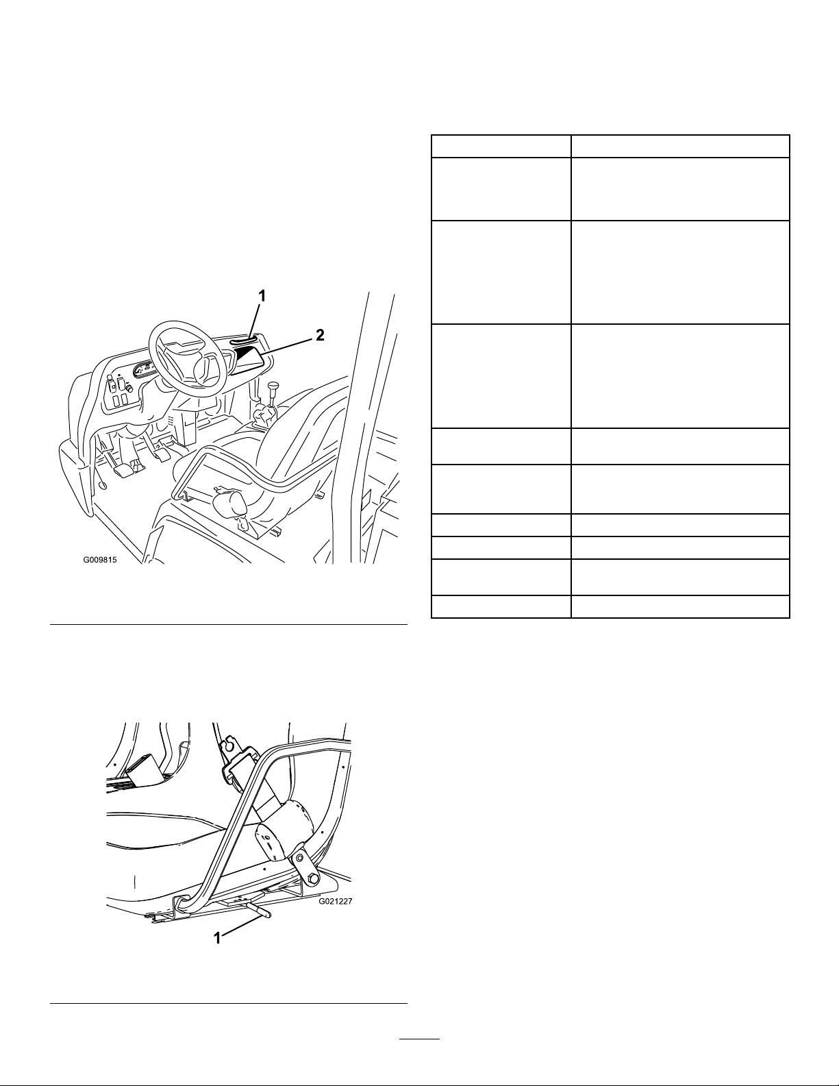
Seat-AdjustmentLever
Theseatscanbeadjustedforwardandrearwardforoperator
comfort(Figure11).
Figure11
1.Seat-adjustmentlever
Attachments/Accessories
AselectionofToroapprovedattachmentsandaccessoriesis
availableforusewiththemachinetoenhanceandexpand
itscapabilities.ContactyourAuthorizedServiceDealeror
Distributororgotowww .Toro.comforalistofallapproved
attachmentsandaccessories.
18
Page 19

Operation
Note:Determinetheleftandrightsidesofthemachine
fromthenormaloperatingposition.
CAUTION
Beforeservicingormakingadjustmentstothe
machine,shutofftheengine,settheparkingbrake,
andremovethekeyfromtheswitch.Removeany
loadmaterialfromthebedorotherattachment
beforeworkingunderaraisedbed.Neverwork
underaraisedbedwithoutpositioningthesafety
supportonafullyextendedcylinderrod.
OperatingtheCargoBox
Figure12
1.Cargo-boxlever
Note:Ifpossible,centerloadsinthecargobox.
Note:Removeallcargofromtheboxbeforeliftingthebox
uptoservicethemachine.
RaisingtheCargoBox
WARNING
Drivingthemachinewiththecargoboxraisedmay
causethemachinetotiporrolleasier.Thebox
structuremaybecomedamagedifyouoperatethe
machinewiththeboxraised.
•Onlyoperatethemachinewhenthecargobox
isdown.
•Afteremptyingthecargobox,lowerit.
CAUTION
Ifaloadisconcentratednearthebackofthecargo
boxwhenyoureleasethelatches,theboxmay
unexpectedlytipopeninjuringyouorbystanders.
LoweringtheBox
WARNING
Theweightoftheboxmaybeheavy.Handsor
otherbodypartscouldbecrushed.
Keephandsandotherbodypartsclearwhen
loweringthebox.
Movetheleverforwardtolowerthecargobox(Figure12).
OpeningtheTailgate
1.Ensurethatthecargoboxisloweredcompletely.
2.Openthelatchesontheleftandrightsideofthecargo
boxandlowerthetailgate(Figure13).
•Centerloadsinthecargoboxifpossible.
•Holdthecargoboxdownandensurethatno
oneisleaningovertheboxorstandingbehindit
whenreleasingthelatches.
•Removeallcargofromtheboxbeforeliftingthe
boxuptoservicethemachine.
Movetheleverrearwardtoraisethecargobox(Figure12).
19
Page 20

G016095
orbelowtheAddmarkonthedipstick,addoiltobringthe
oilleveltotheFullmark.Donotoverlltheenginewith
oil.IftheoillevelisbetweentheFullandAddmarks,no
additionaloilisrequired.
1.Positionthemachineonalevelsurface.
2.Removethedipstickandwipeitwithacleanrag
(Figure15).
Figure13
1.Latchhandle3.Latchpin
2.Latchgate
CheckingtheEngine-OilLevel
ServiceInterval:Beforeeachuseordaily
Engine-oiltype:DetergentengineoilAPISJorhigher
Engine-oilviscosity:10W-30;Chooseanengine-oil
viscosityaccordingtotheambient-airtemperaturetothe
tableinFigure14.
Figure14
Figure15
1.Fillercap
2.Dipstick
3.Insertthedipstickintothetubeandmakesurethatit
isseatedfully(Figure15).
4.Removedipstickandchecktheleveloftheoil(Figure
15).
5.Iftheoillevelislow,removethellercap(Figure15),
andaddenoughoiltoraisetheleveltotheFullmark
onthedipstick.
Note:Whenaddingoil,removedipsticktoallow
properventing.Pourtheoilslowlyandcheckthelevel
oftenduringthisprocess.Donotoverlltheengine
withoil.
Important:Whenaddingengineoilorlling
oil,theremustbeclearancebetweentheoilll
deviceandtheoilllholeinthevalvecoveras
showninFigure16.Thisclearanceisnecessary
topermitventingwhenlling,whichpreventsoil
fromoverrunningintothebreather.
Theengineisshippedwithoilinthecrankcase;however,you
shouldchecktheoillevelbeforeandaftertheengineisrst
started.
Note:Thebesttimetochecktheengineoiliswhenthe
engineiscoolbeforeithasbeenstartedfortheday.Ifithas
alreadyran,allowtheoiltodrainbackdowntothesump
foratleast10minutesbeforechecking.Iftheoillevelisat
20
Page 21

Figure16
DANGER
Incertainconditions,fuelisextremelyammable
andhighlyexplosive.Areorexplosionfromfuel
canburnyouandothersandcandamageproperty.
•Fillthefueltankoutdoors,inanopenarea,when
theengineiscold.Wipeupanyfuelthatspills.
•Neverllthefueltankinsideanenclosedtrailer.
•Donotllthefueltankcompletelyfull.Add
fueltothefueltankuntilthelevelis6to13mm
(1/4to1/2inch)belowthebottomoftheller
neck.Thisemptyspaceinthetankallowsfuel
toexpand.
•Neversmokewhenhandlingfuel,andstayaway
fromanopenameorwherefuelfumesmaybe
ignitedbyaspark.
1.Noteclearance
6.Installthedipstickrmlyinplace(Figure15).
RespondingtoaCheck-Engine Light
Note:Engine-faultcodeinformationcanonlybeaccessed
byyourT orocommercialproductsservicestaff.
1.Parkthevehicleinasafemannerassoonpossible.
2.ContactyourauthorizedT oroservicedealer.
Note:Scheduleaservicecallorbringthemachinein
tobeanalyzed.
AddingFuel
•Forbestresults,useonlyclean,fresh(lessthan30days
old),unleadedgasolinewithanoctaneratingof87or
higher((R+M)/2ratingmethod).
•Ethanol:Gasolinewithupto10%ethanol(gasohol)
or15%MTBE(methyltertiarybutylether)byvolume
isacceptable.EthanolandMTBEarenotthesame.
Gasolinewith15%ethanol(E15)byvolumeisnot
approvedforuse.Neverusegasolinethatcontains
morethan10%ethanolbyvolume,suchasE15
(contains15%ethanol),E20(contains20%ethanol),or
E85(containsupto85%ethanol).Usingunapproved
gasolinemaycauseperformanceproblemsand/orengine
damagewhichmaynotbecoveredunderwarranty.
•Donotusegasolinecontainingmethanol.
•Donotstorefueleitherinthefueltankorfuelcontainers
overthewinterunlessafuelstabilizerisused.
•Storefuelinanapprovedcontainerandkeepit
outofthereachofchildren.Neverbuymore
thana30-daysupplyoffuel.
•Donotoperatewithoutentireexhaustsystemin
placeandinproperworkingcondition.
DANGER
Incertainconditionsduringfueling,static
electricitycanbereleasedcausingasparkwhich
canignitethefuelvapors.Areorexplosionfrom
fuelcanburnyouandothersandcandamage
property.
•Alwaysplacefuelcontainersonthegroundaway
fromyourvehiclebeforelling.
•Donotllfuelcontainersinsideavehicleoron
atruckortrailerbedbecauseinteriorcarpets
orplastictruckbedlinersmayinsulatethe
containerandslowthelossofanystaticcharge.
•Whenpractical,removegas-poweredequipment
fromthetruckortrailerandrefueltheequipment
withitswheelsontheground.
•Ifthisisnotpossible,thenrefuelsuch
equipmentonatruckortrailerfromaportable
container,ratherthanfromagasolinedispenser
nozzle.
•Ifyoumustuseafuel-dispensernozzle,keepthe
nozzleincontactwiththerimofthefueltank
orcontaineropeningatalltimesuntilfuelingis
complete.
•Donotaddoiltogasoline.
21
Page 22

WARNING
Fuelisharmfulorfatalifswallowed.Long-term
exposuretovaporscancauseseriousinjuryand
illness.
•Avoidprolongedbreathingofvapors.
•Keepfaceawayfromnozzleandfueltankor
conditionerbottleopening.
•Avoidcontactwithskin;washoffanyspillswith
soapandwater.
UsingStabilizer/Conditioner
Useafuelstabilizer/conditionerinthemachinetoprovide
thefollowingbenets:
•Keepsgasolinefreshduringstorageof90daysorless.
Forlongerstorageitisrecommendedthatthefueltank
bedrained.
•Cleanstheenginewhileitruns
•Eliminatesgum-likevarnishbuildupinthefuelsystem,
whichcauseshardstarting
Important:Donotusefueladditivescontaining
methanolorethanol.
Addthecorrectamountofgasstabilizer/conditionerto
thegas.
Note:Afuelstabilizer/conditionerismosteffective
whenmixedwithfreshgasoline.T ominimizethechance
ofvarnishdepositsinthefuelsystem,usefuelstabilizer
atalltimes.
3.Fillthetanktoaboutoneinchbelowthetopofthe
tank,(bottomofthellerneck),theninstallthecap.
Note:Donotoverllthefueltank.
4.Wipeupanyfuelthatmayhavespilledtopreventa
rehazard.
CheckingtheCoolantLevel
ServiceInterval:Beforeeachuseordaily
Coolingsystemcapacity:3.7L(4USqt)
Coolanttype:a50/50solutionofwaterandpermanent
ethylene-glycolantifreeze.
CAUTION
Iftheenginehasbeenrunning,thepressurized,hot
coolantcanescapeandcauseburns.
•Donotopentheradiatorcap.
•Allowtheenginetocoolatleast15minutesor
untilthereservetankiscoolenoughtotouch
withoutburningyourhand.
•Usearagwhenopeningthereservetankcap,
andopenthecapslowlytoallowsteamto
escape.
•Donotcheckthecoolantlevelattheradiator;
onlycheckthecoolantlevelatthereservetank.
FillingtheFuelTank
1.Cleantheareaaroundthefuel-tankcap.
2.Removethefuel-tankcap(Figure17).
Figure17
1.Fuel-tankcap
1.Parkthemachineonalevelsurface.
2.Checkthecoolantlevelinsidethereservetank(Figure
18).
Note:Thecoolantshouldbeuptothebottomofthe
llerneckwhentheengineiscold.
22
Page 23

Figure18
Checkingthe Transaxle/Hydraulic-Fluid Level
ServiceInterval:Beforeeachuseordaily(checktheuid
levelbeforetheengineisrststartedand
every8hoursordaily ,thereafter.)
Transaxleuidtype:DexronIIIATF
1.Positionthemachineonalevelsurface.
2.Cleantheareaaroundthedipstick(Figure19).
1.Reserve-tankcap
2.Reservetank
3.Ifthecoolantislow,removethereservetankcap
andadda50/50mixtureofwaterandpermanent
ethylene-glycolantifreeze.
Note:Donotoverllthereservetankwithcoolant.
4.Installthereserve-tankcap.
Figure19
1.Dipstick
3.Unscrewthedipstickfromthetopofthetransaxleand
wipeitwithacleanrag.
4.Screwthedipstickintothetransaxleandensurethat
itisfullyseated.
5.Unscrewthedipstickandchecktheuidlevel.
Note:Theuidshouldbeuptotopoftheatportion
ofthedipstick.
6.Ifthelevelislow ,addenoughofthespecieduidto
achievetheproperlevel.
23
Page 24

CheckingtheHighFlow Hydraulic-FluidLevel
TCModelsOnly
ServiceInterval:Beforeeachuseordaily(checkthelevelof
hydraulicuidbeforetheengineisrst
started,anddailythereafter)
Hydraulic-uidtype:T oroPremiumAllSeason
HydraulicFluid(Availablein5gallonpailsor55gallon
drums.SeepartscatalogorTorodistributorforpart
numbers.)
3.Removethedipstick(Figure20)fromthellerneck
andwipeitwithacleanrag.
4.Insertthedipstickintothellerneck,thenremoveit
andchecktheuidlevel.
Note:Theuidlevelshouldbebetweenthe2marks
onthedipstick.
5.Ifthelevelislow ,addtheappropriateuidtoraise
theleveltotheuppermark;refertoChangingthe
High-FlowHydraulicFluidandFilter(page55).
6.Installthedipstickandcapontothellerneck.
7.Starttheengineandturnontheattachment.
Alternateuids:IftheTorouidisnotavailable,another
conventionalpetroleum–baseduidmaybeusedprovided
itmeetsthefollowingmaterialpropertiesandindustry
specications.Consultwithyourlubricantdistributorto
identifyasatisfactoryproduct.
Note:Torowillnotassumeresponsibilityfordamage
causedbyimpropersubstitutions,souseonlyproducts
fromreputablemanufacturerswhowillstandbehindtheir
recommendation.
HighViscosityIndex/LowPourPointAntiwear
HydraulicFluid,ISOVG46
MaterialProperties:
•Viscosity—ASTMD445cSt@40ºC:44to48/cSt@
100ºC:7.9to8.5
•ViscosityIndex,ASTMD2270—140to152
•PourPoint,ASTMD97—-35ºFto-46ºF
•FZG,Failstage—11orbetter
•Watercontent(newuid)—500ppm(maximum)
IndustrySpecications:
VickersI-286-S,VickersM-2950-S,DenisonHF-0,Vickers
35VQ25(EatonATS373-C)
1.Cleantheareaaroundthellerneckandthecapofthe
hydraulictank(Figure20).
2.Removethecapfromthellerneck.
Note:Letthemrunforabout2minutestopurgeair
fromthesystem.
Important:Themachinemustberunningbefore
startingthehigh-owhydraulics.
8.Shutofftheengineandattachmentandcheckforleaks.
WARNING
Hydraulicuidescapingunderpressurecan
penetrateskinandcauseinjury.
•Makesurethatallhydraulicuidhoses
andlinesareingoodconditionandall
hydraulicconnectionsandttingsaretight
beforeapplyingpressuretothehydraulic
system.
•Keepyourbodyandhandsawayfrom
pinholeleaksornozzlesthateject
high-pressurehydraulicuid.
•Usecardboardorpapertondhydraulic
leaks.
•Safelyrelieveallpressureinthehydraulic
systembeforeperforminganyworkonthe
hydraulicsystem.
•Seekimmediatemedicalattentionifuid
isinjectedintoyourskin.
Figure20
1.Cap
24
Page 25

Checkingthe
CheckingtheTirePressure
Front-Differential-OilLevel
4-Wheel-DriveModelsOnly
ServiceInterval:Every100hours/Monthly(whichever
comesrst)
Differential-oiltype:Mobil424hydraulicoil
1.Positionthemachineonalevelsurface.
2.Cleantheareaaroundthell/checkplugonsideof
thedifferential(Figure21).
ServiceInterval:Beforeeachuseordaily
Theairpressureinthefronttiresshouldbe220kPa(32psi)
andthereartiresshouldbe124kPa(18psi).
Important:Checkthetirepressurefrequentlytoensure
properination.Ifthetiresarenotinatedtothecorrect
pressure,thetireswillwearprematurelyandmaycause
4-wheeldrivetobind.
Figure22isanexampleoftirewearcausedbyunderination.
Figure22
1.Under-inatedtire
Figure21
1.Fill/checkplug
3.Removethell/checkplugandcheckthelevelofthe
oil.
Note:Theoilshouldbeuptohole.
4.Iftheoilislow,addspeciedoil.
5.Installthell/checkplug.
2.Drainplug
CheckingtheTorqueofthe WheelNuts
ServiceInterval:Aftertherst2hours
Aftertherst10hours
Every200hours
WARNING
Failuretomaintainpropertorqueofthewheelnuts
couldresultinfailureorlossofawheelandmay
resultinpersonalinjury.
Torquethefrontandrearwheelnutsto109to122
N·m(80to90ft-lb)after1to4hoursofoperation
andagainafter10hoursofoperation.T orqueevery
200hoursthereafter.
Figure23isanexampleoftirewearcausedbyoverination.
Figure23
1.Over-inatedtire
CheckingtheBrake-Fluid Level
ServiceInterval:Beforeeachuseordaily—Checkthe
brake-uidlevel.(Checkthelevelbefore
theengineisrststartedandevery8
hoursordaily,thereafter.)
Every1,000hours/Every2years(whichevercomes
rst)—Changethebrakeuid.
Brakeuidtype:DOT3brakeuid
Thebrake-uidreservoirislocatedunderthedash.
1.Parkthemachineonalevelsurface.
25
Page 26

2.EnsurethattheuidlevelisuptotheFulllineonthe
reservoir(Figure24).
StartingtheEngine
1.Sitontheoperator’sseatandengagetheparkingbrake.
2.DisengagethePTOandthehigh-owhydraulics(if
equipped)andmovethethrottlelevertotheOFF
position(ifequipped).
3.MovetheshiftlevertotheNEUTRALpositionand
presstheclutchpedal.
4.Ensurethatthehydraulic-liftleverisinthecenter
position.
5.Keepyourfootofftheacceleratorpedal.
6.Insertthekeyintotheignitionswitchandrotateit
clockwisetostarttheengine.
Figure24
1.Brake-uidreservoir
3.Iftheuidlevelislow,cleantheareaaroundthecap,
removethereservoircap,andllthereservoirtothe
properlevelwiththespeciedbrakeuid(Figure24).
Note:Donotoverllthereservoirwithbrakeuid.
Note:Youcanremovethehoodaccesstothereservoirfrom
thefrontofthemachine(Figure25).
Note:Releasethekeywhentheenginestarts.
Important:T opreventoverheatingofthestartermotor,
donotengagestarterlongerthan15seconds.After15
secondsofcontinuouscranking,wait60secondsbefore
engagingthestartermotoragain.
DrivingtheMachine
1.Releasetheparkingbrake.
2.Fullypresstheclutchpedal.
3.Movethegear-shiftlevertorstgear.
4.Releasetheclutchpedalsmoothlywhilepressingthe
acceleratorpedal.
5.Whenthemachinegainsenoughspeed,removeyour
footfromtheacceleratorpedal,fullypresstheclutch
pedal,movethegear-shiftlevertothenextgear,and
releasetheclutchpedalwhilepressingtheaccelerator
pedal.
6.Repeattheprocedureuntilthedesiredspeedisattained.
Important:Alwaysstopthemachinebefore
shiftingtoreversefromaforwardgearortoa
forwardgearfromreverse.
1.Brake-uidreservoir
Figure25
Note:Avoidlongperiodsofengineidling.
Usethechartbelowtodeterminethegroundspeedof
thevehicleat3,600rpm.
Gear
1L82.83:14.72.9
2L54.52:17.24.5
3L31.56:112.5
1H32.31:112.27.6
2H21.27:118.511.5
3H12.31:131.919.8
RL86.94:14.52.8
RH33.91:111.67.1
26
RangeRatio
Speed
(kmh)
Speed
(mph)
7.7
Page 27

Important:Donotattempttopushortowthe
machinetogetitstarted.Damagetothedrive
traincouldresult.
StoppingtheMachine
Tostopthemachine,removeyourfootfromtheaccelerator
pedal,presstheclutchpedal,thenpressthebrakepedal.
ShuttingOfftheEngine
Toshutofftheengine,rotatetheignitionkeytotheOFF
position,andengagetheparkingbrake.Removethekeyfrom
theswitchtopreventaccidentalstarting.
CheckingtheSafety-Interlock System
ServiceInterval:Beforeeachuseordaily
Thepurposeofthesafety-interlocksystemistopreventthe
enginefromcrankingorstartingunlesstheclutchpedalis
pressed.
CAUTION
Ifthesafety-interlockswitchesaredisconnectedor
damagedthemachinecouldoperateunexpectedly
causingpersonalinjury.
•Donottamperwiththeinterlockswitches.
BreakinginaNewMachine
Toprovideproperperformanceandlongmachinelife,follow
theseguidelinesfortherst100operatinghours.
•Checktheuidandengine-oillevelsregularlyandbealert
forindicationsofoverheatinginanycomponentofthe
machine.
•Afterstartingacoldengine,letitwarmupforabout15
secondsbeforeshiftingintogear.
•Avoidracingtheengine.
•Toensureoptimumperformanceofthebrakesystem,
burnish(break-in)thebrakesbeforeuse.Toburnishthe
brakes,bringthevehicleuptofullspeed,applythebrakes
torapidlystopthevehiclewithoutlockingupthetires.
Repeatthis10times,waiting1minutebetweenstopsto
avoidoverheatingthebrakes.Thisismosteffectiveifthe
machineisloadedwith454kg(1,000lb).
•Varythemachinespeedduringoperation.Avoidexcessive
idling.Avoidfaststartsandquickstops.
•Abreak–inoilfortheengineisnotrequired.The
originalengineoilisthesametypespeciedforregular
oilchanges.
•RefertotheMaintenance(page34)sectionforanyspecial
low-hourchecks.
•Checktheoperationoftheinterlockswitches
dailyandreplaceanydamagedswitchesbefore
operatingthemachine.
Note:RefertoAttachmentOperator’sManualforprocedures
oncheckingtheattachmentinterlocksystem.
VerifyingtheClutch-InterlockSwitch
1.Sitontheoperator’sseatandengagetheparkingbrake.
2.MovetheshiftlevertotheNEUTRALposition.
Note:Theenginedoesnotstartifthehydraulic-lift
leverislockedintheforwardposition.
3.Withoutpressingtheclutchpedal,rotatetheignition
keyclockwisetotheSTARTposition.
Note:Iftheenginecranksorstarts,thereisa
malfunctionintheinterlocksystemthatmustbe
repairedbeforeoperatingthemachine.
VerifyingtheHydraulic-LiftLever
InterlockSwitch
1.Sitontheoperator’sseatandengagetheparkingbrake.
2.MovetheshiftlevertotheNEUTRALpositionand
ensurethatthehydraulic-liftleverisinthecenter
position.
3.Pressclutchpedal.
4.Movethehydraulic-liftleverforwardandrotatethe
ignitionkeyclockwisetotheSTARTposition.
Note:Ifenginecranksorstarts,thereisamalfunction
intheinterlocksystemthatmustberepairedbefore
operatingthemachine.
27
Page 28

EnsuringPassengerSafety
EnsuringProperSpeed
Wheneveryouhaveapassengerridinginthemachine,make
surethatheorsheiswearingtheseatbeltandholdingon
securely.Driveslowerandturnlesssharplybecauseyour
passengerdoesnotknowwhatyouaregoingtodonextand
maynotbepreparedforturning,stopping,accelerating,and
bumps.
Youandyourpassengershouldremainseatedatalltimes,
keepingarmsandlegsinsidethevehicle.Theoperatorshould
keepbothhandsonsteeringwheel,wheneverpossible,and
thepassengershouldusethehandholdsprovided(Figure
26andFigure27).
Speedisoneofthemostimportantvariablesleadingto
accidents.Drivingtoofastfortheconditionscancauseyou
tolosecontrolandhaveanaccident.Speedcanalsomakea
minoraccidentworse.Drivingheadonintoatreeatslow
speedcancauseinjuryanddamage,but,drivingintoatree
athighspeedcandestroythevehicleandkillyouandyour
passenger.
Neverdrivetoofastfortheconditions.Ifthereisanydoubt
abouthowfasttodrive,slowdown.
Whenusingheavyattachments,morethan454kg(1,000
lb),suchassprayers,topdressers,orspreaders,etc.,restrict
youroperatingspeedbymovingthesupervisorswitchtothe
slowposition.
EnsuringProperTurning
Turningisanotherimportantvariableleadingtoaccidents.
Turningtoosharplyfortheconditionscancausethevehicle
tolosetractionandskid,oreventipover.
Wet,sandy,andslipperysurfacesmaketurningmoredifcult
andrisky .Thefasteryouaregoing,theworsethissituation
becomesso,slowdownbeforeturning.
Figure26
1.Passenger-handhold
1.Handholdandhiprestraint
Neverallowpassengersinthecargoboxoronany
attachments.Thevehicleismeanttohave1driverandonly
1passenger.
2.Storagecompartment
Figure27
Duringasharpturnathigherspeeds,theinsiderearwheel
mayliftofftheground.Thisisnotaawinthedesign,it
happenswithmost4-wheelmachineincludingpassengercars.
Ifthishappens,youareturningtoosharplyforthespeedat
whichyouaretraveling.
EnsuringProperBraking
Itisgoodpracticetoslowdownbeforeyougetnearan
obstacle.Thisgivesyouextratimetostoporturnaway.
Hittinganobstaclecandamagethemachineanditscontents.
Moreimportant,itcaninjureyouandyourpassenger.Gross
machineweighthasamajorimpactonyourabilitytostop
and/orturn.Heavierloadsandheavierattachmentsmake
avehiclehardertostoporturn.Theheaviertheload,the
longerittakestostop.
Thebrakingcharacteristicsalsochangewithnobedor
attachmentonthemachine.Faststopsmaycausetherear
wheelstolockupbeforethefrontwheelslockup,whichmay
affectthecontrolofthemachine.Itisagoodideatodecrease
machinespeedwithnobedorattachment.
Turfandpavementaremuchslipperierwhentheyarewet.
Itcantake2to4timesaslongtostoponwetsurfacesas
ondrysurfaces.
Ifyoudrivethroughstandingwaterdeepenoughtogetthe
brakeswet,theywillnotworkwelluntiltheyaredry.After
drivingthroughwater,youshouldtestthebrakestomake
suretheyworkproperly.Iftheydonot,driveslowlyinrst
gearwhileputtinglightpressureonthebrakepedal.This
willdryoutthebrakes.
28
Page 29

Donotdownshiftforbrakingonicyorslipperysurfaces(wet
grass)orwhilegoingdownahillbecauseenginebraking
maycauseskiddingandlossofcontrol.Shifttoalowergear
beforestartingdownahill.
PreventingTipOvers
Themachineisequippedwitharollbar,hiprestraints,
seatbelts,andhandhold.TheRollover-ProtectionSystem
(ROPS)usedonthemachinewillreducetheriskofserious
orfatalinjuryintheunlikelyeventofatipover,althoughthe
systemcannotprotecttheoperatorfromallpossibleinjuries.
ReplaceadamagedROPS;donotrepairorrevise.Any
alterationoftheROPSmustbeapprovedbythemanufacturer.
Thebestwaytopreventaccidentsinvolvingutilitymachine
isthroughcontinuoussupervisionandtrainingofoperators
andpayingconstantattentiontotheareawheretheyare
operatingthevehicle.
Thebestwayforoperatorstopreventseriousinjuryordeath
tothemselvesorothersistofamiliarizethemselveswiththe
properoperationoftheutilityvehicle,tostayalertandto
avoidactionsorconditionswhichcouldresultinaaccident.
Intheeventofatipover,theriskofseriousinjuryordeath
willbereducediftheoperatorisusingtheROPSsystemand
seatbeltsandisfollowingtheinstructionsprovided.
OperatingonHills
WARNING
Tippingorrollingthemachineonahillcouldcause
seriouspersonalinjury.
•Donotoperatethevehicleonsteepslopes.
•Ifenginestallsoryouloseheadwayonahill,
neverattempttoturnvehiclearound.
•Alwaysbackstraightdownahillinreversegear.
•Neverbackdowninneutralorwiththeclutch
depressed,usingonlythebrakes.
•Neverdriveacrossasteephill,alwaysdrive
straightupordown.
•Avoidturningonahill.
•Don’t“droptheclutch”orslamonthebrakes.
Suddenspeedchangecaninitiateatipover.
andcautiouslyaspossible.Nevermakesharporfastturns
onahill.
Ifyoustallorbegintoloseheadwaywhileclimbingasteep
hill,quicklyapplythebrakes,shifttoneutral,starttheengine
andshifttoreverse.Atidlespeed,theengineandtransaxle
dragwillaidthebrakesincontrollingthevehicleonthehill
andhelpyoubackdownthehillmoresafely.
Reducetheweightoftheloadifitisasteephillorifthe
loadhashighcenterofgravity.Remember,loadscanshift,
securethem.
Note:Themachinehasexcellenthill-climbingability.The
differentiallockwillincreasethisability.Hillclimbingtraction
canalsobeincreasedbyaddingweighttotherearofthe
vehicleinoneofthefollowingways:
•Addingweighttoinsideofbox,makingsureitissecured.
•Mountingwheelweightstorearwheels.
•Addingliquidballast(calciumchloride)toreartires.
•Tractionwillincreasewithnopassengerinfrontseat.
LoadingandDumping
Theweightandpositionofthecargoandpassengercan
changethemachinecenterofgravityandmachinehandling.
Toavoidlossofcontrolresultinginpersonalinjury,follow
theseguidelines.
Donotcarryloadswhichexceedtheloadlimitsdescribed
onthemachine-weightlabel.
WARNING
Thebedwilllowerwheneverthedumpleveris
pusheddown,evenwhentheengineisoff.Turning
not
offtheenginewill
lowering.Alwaysplacethesafetysupportonthe
extendedliftcylindertoholdtheboxupifyouare
notgoingtoloweritrightaway.
Themachinehasseveralcombinationsofboxes,platforms,
andattachmentsavailable.Thesecanbeusedinvarious
combinationsthatallowformaximumcapacityandversatility.
Thefullsizedboxis140cm(55inches)wideby165cm
(65inches)longandcanholdupto1,477kg(3,249lb)of
evenly-distributedcargo.
preventtheboxfrom
Useextracarewhenonhills.Nevergoonhillsthatare
extremelysteep.Stoppingwhilegoingdownahillwilltake
longerthanonlevelground.Turningwhilegoingupordown
ahillismoredangerousthanturningonthelevel.Turnswhile
goingdownhill,especiallywiththebrakeson,and,turning
uphillwhiletraversingahillareparticularlydangerous.Even
ataslowspeedandwithoutaload,tipoversaremorelikelyif
youturnonahill.
Slowdownandshiftintoalowergearbeforestartingupor
downahill.Ifyouhavetoturnwhileonahill,doitasslowly
Loadsvaryinhowtheyaredistributed.Sandspreadsout
evenlyandquitelow .Otheritems,suchasbricks,fertilizeror
landscapetimbers,stackhigherinthebox.
Theheightandweightoftheloadhasasignicantinuence
ontipovers.Thehigheraloadisstacked,themorelikelythe
vehicleistotipover.Youmayndthat1,477kg(3,249lb)
stackstoohighforsafeoperation.Reducingthetotalweight
isonewaytoreducetheriskofatipover.Distributingthe
loadaslowaspossibleisanotherwaytoreducetheriskof
atipover.
29
Page 30

Iftheloadispositionedtowardoneofthesides,itwillmake
themachinemuchmorelikelytotipoveronthatside.This
isespeciallytruewhenturningiftheloadisontheoutside
oftheturn.
WARNING
Tippingorrollingthemachineonahillwillcause
seriousinjury.
Neverpositionheavyloadsbehindtherearaxle.Iftheloadis
positionedsofartotherearthatitisbehindtherearaxle,it
willreducetheweightonthefrontwheelsandthiswillreduce
steeringtraction.Withtheloadallthewaytotheback,the
frontwheelscanevencomeoffofthegroundwhengoing
overbumpsorupahill.Thiswillresultinalossofsteering
andmayleadtothemachinetippingover.
Asageneralrule,positiontheweightoftheloadevenly
fromfronttorearandevenlyfromsidetoside.
Ifaloadisnotsecured,oryouaretransportingaliquidina
largecontainersuchasasprayer,itcanshift.Thisshifting
happensmostoftenwhileturning,goingupordownhills,
suddenlychangingspeeds,orwhiledrivingoverrough
surfaces.Shiftingloadscanleadtotipovers.Alwayssecure
loadssothattheydonotshift.Neverdumptheloadwhile
themachineissidewaysonthehill.
Heavyloadsincreasestoppingdistanceandreduceyour
abilitytoturnquicklywithouttippingover.
Therearcargospaceisintendedforloadcarryingpurposes
only,notforpassengers.
UsingtheDifferentialLock
Thedifferentiallockincreasesthemachinetractionbylocking
therearwheelssoonewheelwillnotspinout.Thiscanhelp
whenyouhaveheavyloadstohaulonwetturforslippery
areas,goinguphills,andonsandysurfaces.Itisimportant
toremember,however,thatthisextratractionisonlyfor
temporarylimiteduse.Itsusedoesnotreplacethesafe
operation,alreadydiscussedconcerningsteephillsandheavy
loads.
Thedifferentiallockcausestherearwheelstospinatthe
samespeed.Whenusingthedifferentiallock,yourabilityto
makesharpturnsissomewhatrestrictedandmayscuffthe
turf.Usethedifferentiallockonlywhenneeded,atslower
speedsandonlyinrstorsecondgear.
•Theextratractionavailablewiththedifferential
lockcanbeenoughtogetyouintodangerous
situationssuchasclimbingslopesthataretoo
steeptoturnaround.Beextracarefulwhen
operatingwiththedifferentiallockon,especially
onsteeperslopes.
•Ifthedifferentiallockisonwhenmakinga
sharpturnatahigherspeedandtheinsiderear
wheelliftsofftheground,theremaybealossof
controlwhichcouldcausevehicletoskid.Use
thedifferentiallockonlyatslowerspeeds.
Using4-WheelDrive
4-Wheel-DriveModelsOnly
TheAutomatic,onDemand4-wheel-drivefeature,onthis
vehicledoesnotrequireoperatoractivation.Thefrontwheel
driveisnotengaged(nopowerdeliveredtofrontwheels)
untiltherearwheelsbegintolosetraction.Thebidirectional
clutchsensestherearwheelsslipping,engagesthefront
wheeldrive,anddeliverspowertothefrontwheels.The
4-wheel-drivesystemcontinuestodeliverpowertothefront
wheelsuntiltherearwheelshaveenoughtractiontomove
thevehiclewithoutslipping.Oncethisoccurs,thesystem
stopsdeliveringpowertothefrontwheelsandthehandling
characteristicsbecomesimilartothatofa2-wheel-drive
machine.The4wheeldrivesystemfunctionsinbothfroward
andreverse,however,whenturningtherearwheelswillslip
slightlymorebeforepowerisdeliveredtothefrontwheels.
WARNING
Tippingorrollingthemachineonahillwillcause
seriousinjury.
Theextratractionavailablewiththe4-wheel-drive
featurecanbeenoughtogetyouintodangerous
situationssuchasclimbingslopesthataretoo
steeptoturnaround.Becarefulwhenoperating,
especiallyonsteeperslopes.
30
Page 31

TransportingtheMachine
TowingtheMachine
Formovingthemachinelongdistances,useatrailer.Make
surethatthemachineissecuredtothetrailer.RefertoFigure
28andFigure29forthelocationofthetie-downpoints.
Important:Trailersweighingover680kg(1,500lb)are
requiredtobeequippedwithtrailerbrakes.
Note:Loadthemachineonthetrailerwiththefrontofthe
machinefacingforward.Ifthatisnotpossible,securethe
machinehoodtotheframewithastrap,orremovethehood
andtransportandsecureitseparatelyorthehoodmayblow
offduringtransport.
Figure28
1.Eyeholeintheframe(eachside)
Incaseofanemergency ,themachinecanbetowedfora
shortdistance.However,Torodoesnotrecommendthisas
astandardprocedure.
WARNING
Towingatexcessivespeedscouldcausethe
machinetolosesteeringcontrol.Nevertowthe
machineatfasterthan8kph(5mph).
Towingthemachineisa2-personjob.Afxatowlineto
holesinthefrontframemember.Movetheshiftleverto
theNEUTRALpositionandreleasetheparkingbrake.Ifthe
machinemustbemovedaconsiderabledistance,transport
itonatruckortrailer.
Note:Thepowersteeringdoesnotfunction,makingit
difculttosteer.
TowingaTrailerwiththe Machine
Themachineiscapableofpullingtrailersandattachmentsof
greaterweightthanthemachineitself.
Severaltypesoftowhitchesareavailableforthemachine,
dependingonyourapplication.ContactyourAuthorized
ToroDistributorfordetails.
Figure29
1.Axle2.Hitchplate
Whenequippedwithatowhitchboltedontotherearaxle
tube,yourmachinecantowtrailersorattachmentswith
aGrossTrailerW eight(GTW)upto1,587kg(3,500lb).
Alwaysloadatrailerwith60%ofthecargoweightinthe
frontofthetrailer.Thisplacesapproximately10%(272kg
(600lb)max.)oftheGrossTrailerWeight(GTW)onthetow
hitchofthemachine.
Trailerbrakesarerequiredwheneveryoutowatrailerover
680kg(1,500lb)GTWistowedbehindamachine.
Whenhaulingcargoortowingatrailer(attachment),donot
overloadyourmachineortrailer.Overloadingcancausepoor
performanceordamagetothebrakes,axle,engine,transaxle,
steering,suspension,bodystructure,ortires.
Important:Toreducepotentialfordrivelinedamage,
uselowrange.
Whentowingfth-wheelattachments,likeafairwayaerator,
alwaysinstallthewheelbar(includedwiththefthwheelkit)
topreventthefrontwheelsfromliftingoffthegroundifthe
towedattachmentsmovementissuddenlyimpaired.
31
Page 32

UsingtheHydraulicControl
Thehydrauliccontrolsupplieshydraulicpowerfromthe
machinepumpwhenevertheengineruns.Thepowercanbe
usedthroughthequickcouplersattherearofthemachine.
CAUTION
Hydraulicuidescapingunderpressurecanhave
sufcientforcetopenetrateskinanddoserious
damage.Caremustbeusedwhenconnectingor
disconnectinghydraulicquickcouplers.Shutoff
theengine,applytheparkingbrake,lowerthe
attachment,andplacetheremotehydraulicvalvein
theoatdetentpositiontorelievehydraulicpressure
beforeconnectingordisconnectingquickcouplers.
Thispositionwilllowerthebed,rearhitchattachment,
orapplypressuretoquickcouplerB.Thisalsoallows
hydraulicuidtoreturnfromquickcouplerAtoow
backintothevalveandthenouttothereservoir.Thisis
amomentarypositionandwhentheleverisreleasedit
springreturnstothecenteroffposition.Momentarily
holdingandthenreleasingthecontrolleverinthis
positionwillprovidehydraulic-uidowtoquickcoupler
Bwhichprovidespowerdownontherearhitch.When
released,itwillholdthedownpressureonthehitch.
Important:Ifusedwithahydrauliccylinder,
holdingthecontrolleverinthelowerpositioncauses
thehydraulic-uidowtogooverareliefvalvewhich
candamagethehydraulicsystem.
•ONPosition
Important:Ifmultiplemachinesusethesame
attachment,crosscontaminationofthetransmission
uidmayoccur.Changethetransmissionuidmore
frequently
UsingtheHydraulic-Bed-LiftLeverto
ControlHydraulicAttachments
•OFFPosition
Thisisthenormalpositionforthecontrolvalvewhenit
isnotbeingused.Inthispositiontheworkportsofthe
controlvalveareblockedandanyloadwillbeheldbythe
checkvalvesinbothdirections.
•RAISE(QuickCoupler“ A ”Position)
Thisisthepositionwhichwillliftthebed,rearhitch
attachmentorapplypressuretoquickcouplerA.This
alsoallowshydraulicuidtoreturnfromquickcouplerB
toowbackintothevalveandthenouttothereservoir.
Thisisamomentarypositionandwhentheleveris
releaseditspringreturnstothecenter,OFFposition.
ThispositionissimilartoLower(quickcouplerB
position).Italsodirectshydraulicuidtoquickcoupler
Bexceptthattheleverisheldinthispositionbya
detentleverinthecontrolpanel.Thisallowshydraulic
uidtoowcontinuouslytoequipmentthatusesa
hydraulicmotor.Thispositionmustonlybeusedon
attachmentswithahydraulicmotorattached.
Important:Ifusedwithahydrauliccylinder
ornoattachment,theONpositioncausesthe
hydraulic-uidowtogooverareliefvalvewhich
candamagethehydraulicsystem.Usethisposition
onlymomentarilyorwithamotorattached.
Important:Checkthehydraulic-uidlevelafter
installationofanattachment.Checktheoperation
oftheattachmentbycyclingtheattachmentseveral
timestopurgeairfromthesystem,thencheck
hydraulic-uidlevelagain.Theattachmentcylinder
willslightlyaffecttheuidlevelinthetransaxle.
Operatingthevehiclewithalowhydraulic-uidlevel
candamagethepump,remotehydraulics,power
steering,andthevehicletransaxle.
ConnectingtheQuickCouplers
Figure30
1.QuickcouplerAposition2.QuickcouplerBposition
•LOWER(QuickCouplerBPosition)
Important:Cleandirtfromquickcouplersbefore
connecting.Dirtycouplerscanintroducecontamination
intothehydraulicsystem
1.Pullbackthelockingringonthecoupler.
2.Insertthehosenippleintothecoupleruntilitsnaps
intoposition.
Note:Whenattachingremoteequipmenttothequick
couplers,determinewhichsiderequirespressure,thenattach
thathosetoquickcouplerB,whichwillhavepressurewhen
thecontrolleverispushedforwardorlockedintheON
position.
32
Page 33

DisconnectingtheQuickCouplers
Note:Withboththevehicleandattachmentturnedoff,
movetheliftleverbackandforthtoremovethesystem
pressureandeasethedisconnectionofthequickcouplers.
1.Pullbackthelockingringonthecoupler.
2.Pullthehosermlyfromthecoupler.
Important:Cleanandinstallthedustplugand
dustcoverstothequickcouplerendswhennot
inuse.
TroubleshootingtheHydraulicControl
•Difcultyinconnectingordisconnectingquickcouplers.
Thepressurenotrelieved(thequickcouplerisunder
pressure).
•Thepowersteeringisturningwithgreatdifcultyorit
isnotturningatall.
–Thehydraulic-uidlevelislow .
–Thehydraulic-uidtemperatureishot.
–Thepumpisnotoperating.
•Therearehydraulicleaks.
–Thettingsareloose.
–Thettingismissingtheo-ring.
•Anattachmentdoesnotfunction.
–Thequickcouplersarenotfullyengaged.
–Thequickcouplersareinterchanged.
•Thereisasquealingnoise.
–RemovethevalveleftintheONdetentposition
causinghydraulicuidtoowoverthereliefvalve.
–Thebeltisloose.
•Theenginedoesnotstart.
Thehydraulicleverislockedintheforwardposition
33
Page 34

Maintenance
Determinetheleftandrightsidesofthemachinefromthenormaloperatingposition.
CAUTION
Onlyqualiedandauthorizedpersonnelshouldmaintain,repair,adjust,orinspectthemachine.
Avoidrehazardsandhavereprotectionequipmentpresentintheworkarea.Donotuseanopename
tochecklevelorleakageoffuel,batteryelectrolyte,orcoolant.Donotuseopenpansoffuelorammable
cleaninguidsforcleaningparts.
CAUTION
Ifyouleavethekeyintheignitionswitch,someonecouldaccidentlystarttheengineandseriouslyinjure
youorotherbystanders.
Removethekeyfromtheignitionbeforeyoudoanymaintenance.
RecommendedMaintenanceSchedule(s)
MaintenanceService
Interval
Aftertherst2hours
Aftertherst10hours
Aftertherst50hours
Beforeeachuseordaily
MaintenanceProcedure
•T orquethefrontandrearwheelnuts.
•T orquethefrontandrearwheelnuts.
•Checktheadjustmentoftheshiftcables.
•Checktheadjustmentoftheparkingbrake.
•Checktheconditionandtensionofthealternatorbelt.
•Replacethehydrauliclter.
•Changethehigh-owhydraulicuidlter(TCmodelsonly).
•Inspectopeningonlter.
•Changetheengineoilandlter.
•Adjusttheengine-valveclearance.
•Checktheengine-oillevel.
•Checkthelevelofthecoolant.
•Checkthetransaxle/hydraulic-uidlevel.(checktheuidlevelbeforetheengine
isrststartedandevery8hoursordaily,thereafter.)
•Checkthehighowhydraulic-uidlevel(TCmodelsonly).(checkthelevelof
hydraulicuidbeforetheengineisrststarted,anddailythereafter)
•Checkthetirepressure.
•Checkthebrake-uidlevel.(Checkthelevelbeforetheengineisrststartedand
every8hoursordaily ,thereafter.)
•Checktheoperationofthesafety-interlocksystem.
•Removedebrisfromtheengineareaandradiator(cleanmorefrequentlyindirty
conditions).
Every25hours
Every50hours
Every100hours
•Removetheair-cleanercoverandcleanoutthedebris.
•Checkthebattery-uidlevel(every30daysifinstorage).
•Checkthebattery-cableconnections.
•Checktheleveloffrontdifferentialoil(4-wheel-drivemodelsonly).
•Greaseallbearingsandbushings(lubricatemorefrequentlyinheavyduty
applications).
•Changetheair-cleanerlter(morefrequentlyindustyordirtyconditions).
•Inspecttheconditionofthetires.
34
Page 35

MaintenanceService
Every200hours
Every400hours
Interval
MaintenanceProcedure
•T orquethefrontandrearwheelnuts.
•Inspectopeningonlter.
•Changetheengineoilandlter.
•Inspecttheconstant-velocitybootforcracks,holes,oralooseclamp(4-wheel-drive
modelsonly).
•Checktheadjustmentoftheshiftcables.
•Checktheadjustmentofthehigh–lowcable.
•Checktheadjustmentofthedifferential-lockcable.
•Checktheadjustmentoftheparkingbrake.
•Checktheadjustmentofthebrakepedal.
•Checktheconditionandtensionofthealternatorbelt.
•Checktheadjustmentoftheclutchpedal.
•Inspecttheserviceandparkingbrakes.
•Inspectorreplacethesparkplugs.
•Replacethefuellter.
•Checkthefuellinesandconnections.
•Checkthefront-wheelalignment.
•Visuallyinspectthebrakesforwornbrakeshoes.
Every600hours
Every800hours
Every1,000hours
•Adjusttheengine-valveclearance.
•Changethefront-differentialoil(4-wheel-drivemodelsonly).
•Changethehydraulicuidandcleanthestrainer .
•Replacethehydrauliclter.
•Changethehigh-owhydraulicuidandlter(TCmodelsonly).
•Changethebrakeuid.
•Drain/ushthefueltank.
•Flushorreplacethecoolant-systemuid.
OperatinginAdverseConditions
Important:Ifthemachineissubjectedtoanyoftheconditionslistedbelow,performmaintenancetwiceas
frequently:
•Desertoperation
•Cold-climateoperationbelow0°C(32°F)
•Trailertowing
•Frequentoperationondustyroads
•Constructionwork
•Afterextendedoperationinmud,sand,water,orsimilardirtyconditions,haveyourbrakesinspectedandcleanedassoonas
possible.Thiswillpreventanyabrasivematerialfromcausingexcessivewear.
35
Page 36

Premaintenance
Procedures
Manyofthesubjectscoveredinthismaintenancesection
requireraisingandloweringthebed.Thefollowing
precautionsmustbetakenorseriousinjuryordeathcould
result.
WARNING
Araisedbedfullofmaterialwithouttheproper
safetysupportrodmaylowerunexpectedly.
Workingunderanunsupportedraisedbedmay
causeinjurytoyouorothers.
•Beforeservicingormakingadjustmentstothe
machine,shutofftheengine,settheparking
brake,andremovethekeyfromtheignition
switch.
•Removeanyloadmaterialfromthebedorother
attachmentandinsertthesafetysupporton
afullyextendedcylinderrodbeforeworking
underaraisedbed.
3.Pushthebedsupportontothecylinderrod,ensuring
thatthesupportendtabsrestontheendofcylinder
barrel,andonthecylinderrodend(Figure32).
Figure32
1.Bedsupport3.Bed
2.Cylinderbarrel
UsingtheBedSupport
Important:Alwaysinstallorremovethebedsupport
fromtheoutsideofthebed.
1.Raisethebeduntiltheliftcylindersarefullyextended.
2.Removethebedsupportfromthestoragebracketson
thebackoftheROPSpanel(Figure31).
4.Removethebedsupportfromthecylinderandinsertit
intothebracketsonthebackoftheROPSpanel.
Important:Donottrytolowerthebedwiththe
bed-safetysupportonthecylinder.
Figure31
1.Bedsupport
36
Page 37

RemovingtheFullBed
InstallingtheFullBed
1.Starttheengine,engagethehydraulic-liftlever,and
lowerthebeduntilthecylindersarelooseintheslots.
2.Releasetheliftleverandturnofftheengine.
3.Removethelynchpinsfromtheouterendsofthe
cylinderrodclevispins(Figure33).
Figure33
1.Cylinderrodend
2.Bed-mountingplate
3.Clevispin6.Frontslots(2/3bed)
4.Lynchpin
5.Rearslots(fullbed)
Note:Ifthebedsideswillbeinstalledontheatbed,itis
easiertoinstallthembeforeinstallingthebedonthemachine.
Note:Ensurethattherearpivotplatesareboltedtothe
bedframe/channelsothatthelowerendanglestotherear
(Figure34).
Figure34
1.Left,rearcornerofbed4.Clevispin
2.Machineframechannel
3.Pivotplate
5.Lynchpin
4.Removetheclevispinssecuringthecylinderrodends
tothebed-mountingplatesbypushingthepinstowards
theinside(Figure33).
5.Removethelynchpinsandclevispinssecuringthe
pivotbracketstotheframechannels(Figure33).
6.Liftthebedoffthemachine.
CAUTION
Thefullbedweighsapproximately148kg
(325lb),sodonottrytoinstallorremoveit
byyourself.
Useanoverheadhoistorgetthehelpof2or3
otherpeople.
7.Storethecylindersinthestorageclips.
8.Engagethehydraulic-lift-lockleveronthemachineto
preventaccidentalextensionoftheliftcylinders.
CAUTION
Thefullbedweighsapproximately148kg(325lb),
sodonottrytoinstallorremoveitbyyourself.
Useanoverheadhoistorgetthehelpof2or3other
people.
Note:Ensurethatthespacerbracketsandwearblocks
(Figure35)areinstalledwiththecarriage-boltheads
positionedinsidethemachine.
37
Page 38

Figure35
1.Wearblock
2.Spacerbracket
1.Ensurethattheliftcylindersarefullyretracted.
2.Carefullysetthebedontothemachineframe,aligning
therearbedpivot-plateholeswiththeholesintherear
framechannelandinstall2clevispinsandlynchpins
(Figure35).
3.Withthebedlowered,secureeachcylinderrodend,to
theappropriateslotsinthebed-mountingplateswitha
clevispinandlynchpin.
3.Carriagebolt
RaisingtheMachine
DANGER
Amachineonajackmaybeunstableandslipoffof
thejack,injuringanyonebeneathit.
•Donotstartthemachinewhilethemachineis
onajack.
•Alwaysremovethekeyfromtheswitchbefore
gettingoffofthemachine.
•Blockthetireswhenthemachineisonajack.
•Donotstarttheenginewhilethemachineisonajack,
becausetheenginevibrationorwheelmovementcould
causethemachinetoslipoffthejack.
•Donotworkunderthemachinewithoutjackstands
supportingit.Themachinecouldslipoffajack,injuring
anyonebeneathit.
•Whenjackingupthefrontofthevehicle,alwaysplacea
woodenblock(orsimilarmaterial)betweenthejackand
themachineframe.
•Thejackingpointatthefrontofthemachineisunderthe
frontcenterframesupport(Figure36)andattherearitis
undertheaxle(Figure37).
4.Inserttheclevispinfromoutsideofthebedwiththe
lynchpintowardtheoutside(Figure35).
Note:Therearslotsareforafullbedinstallationand
frontslotsarefora2/3bedinstallation.
Note:Theenginemayneedtobestartedtoextendor
retractthecylindersforalignmentwiththeholes.
Note:Theunusedslotcanbepluggedwithaboltand
nuttopreventassemblyerrors.
5.Starttheengineandengagethehydraulic-liftleverto
raisethebed.
6.Releasetheliftleverandturnofftheengine.
7.Installthebed-safetysupporttopreventaccidental
loweringofthebed;refertoUsingtheBedSupport
(page36).
8.Installthelynchpinstotheinsideendsoftheclevis
pins.
Note:Iftheautomatic-tailgatereleasehasbeen
installedonthebed,ensurethatthefrontdumplink
rodhasbeenplacedontheinsideoftheleftsideclevis
pinbeforethelynchpinisinstalled.
Figure36
1.Frontjackingpoints
38
Page 39

Figure37
1.Rearjackingpoints
RemovingtheHood
1.Whilegraspingthehoodintheheadlightopenings,lift
upthehoodtoreleasethelowermountingtabsfrom
theframeslots(Figure38).
InstallingtheHood
1.Connectthelights.
2.Insertthetopmountingtabsintotheframeslots.
3.Insertthelowermountingtabsintotheframeslots.
4.Ensurethatthehoodisfullyengagedinthetop,sides
andbottomgrooves.
Figure38
1.Hood
2.Pivotthebottomofthehoodupwarduntilthetop
mountingtabscanbepulledfromtheframeslots
(Figure38).
3.Pivotthetopofthehoodforward,andunplugthewire
connectorsfromtheheadlights(Figure38).
4.Removethehood.
39
Page 40

Lubrication
GreasingtheBearingsand Bushings
ServiceInterval:Every100hours(lubricatemorefrequently
inheavydutyapplications).
Themachinehasgreasettingsthatmustbelubricated
regularlywithNo.2lithiumgrease.
Thegrease-ttinglocationsandquantitiesareasfollows:
•Balljoints(4),tierods(2),pivotmounts(2)andsteering
cylinder(2)asshowninFigure39
•Springtower(2)asshowninFigure40
•Clutch(1)andbrake(1)asshowninFigure41
•U-joint(18)and4wheeldriveshaft(3)asshownin
Figure42
Important:Whengreasingthedriveshaftuniversal
shaftbearingcrosses,pumpgreaseuntilitcomesout
ofall4cupsateachcross.
Figure40
1.Wipeeachgreasettingcleansoforeignmattercannot
beforcedintothebearingorbushing.
2.Pumpgreaseintoeachbearingorbushing.
3.Wipeoffexcessgrease.
Figure39
Figure41
40
Page 41

Figure42
41
Page 42

EngineMaintenance
1
G016089
InspectingtheCarbonCanister AirFilter
ServiceInterval:Aftertherst50hours
Every200hours
1.Locatetheairlteronthebottomofthecarbon
canister(Figure43).
Figure44
1.Air-cleanercover2.Filter
2.Squeezethedustcapsidestoopenitandknockthe
dustout.
3.Gentlyslidethelteroutoftheair-cleanerbody
(Figure44).
Note:Avoidknockingthelterintothesideofthe
body.
Note:Donotattempttocleanthelter.
4.Inspectthenewlterfordamagebylookingintothe
lterwhileshiningabrightlightontheoutsideofthe
lter.
Note:Holesinthelterwillappearasbrightspots.
Inspecttheelementfortears,anoilylm,ordamageto
Figure43
1.Filteropening
2.Ensurethattheopeningonthebottomofthelteris
clearandopen.
ServicingtheAirCleaner
ServiceInterval:Every25hours—Removetheair-cleaner
coverandcleanoutthedebris.
Every100hours—Changetheair-cleanerlter(more
frequentlyindustyordirtyconditions).
therubberseal.Ifthelterisdamageddonotuseit.
Topreventenginedamage,alwaysoperatetheengine
withtheairlterandcoverinstalled.
Takespecialcaretokeepparticulatesfromdropping
intothecleanareasoftheair-lterhousing.
5.Carefullyslidethelteroverthebodytube(Figure44).
Note:Ensurethatitisfullyseatedbypushingonthe
outerrimofthelterwhileinstallingit.
6.Installtheair-cleanercoverwiththesidefacingup,and
securethelatches(Figure44).
Inspecttheaircleanerandhosesperiodicallytomaintain
maximumengineprotectionandtoensuremaximumservice
life.Checktheair-cleanerbodyfordamagewhichcould
possiblycauseanairleak.Replaceadamagedair-cleanerbody .
Inspectandchangetheair-cleanerlterasdescribedinthe
followingprocedure:
1.Releasethelatchesontheaircleanerandpullthe
air-cleanercoverofftheair-cleanerbody(Figure44).
42
Page 43

ChangingtheEngineOiland
G016095
G021292
1
2
Filter
6.Screwthelteronuntilthegasketcontactsthe
mountingplate,thentightenthelter1/2to2/3of
aturn.
ServiceInterval:Aftertherst50hours
Every200hours
Engine-oilquantity:3.2L(3.4USqt)(withalter)
Engine-oiltype:DetergentengineoilAPISJorhigher
Engine-oilviscosity:10W-30;Chooseanengine-oil
viscosityaccordingtotheambient-airtemperaturetothe
tableinFigure45.
Figure45
1.Raisethebed(ifequipped),andplacethesafetysupport
ontheextended-liftcylindertoholdupthebed.
2.Removethedrainplugandlettheoilowintoadrain
pan(Figure46).
Note:Donotovertighten.
7.Addthespeciedoiltothecrankcase;referto
CheckingtheEngine-OilLevel(page20).
ReplacingtheSparkPlugs
ServiceInterval:Every400hours
Thesparkplugsusuallylastsalongtime;however,the
plugsshouldberemovedandcheckedwhenevertheengine
malfunctions,orevery400hours.Replacethesparkplugs
toensureproperengineperformanceandreduceexhaust
emissionlevel.
Usethefollowingsparkplug:NGK-RBKR5E
Therecommendedairgapis0.81mm(0.032inch).
1.Cleantheareaaroundthesparkplugs,sothatforeign
mattercannotfallintothecylinderwhenyouremove
thesparkplug.
2.Pullwiresoffthesparkplugsandremovetheplugs
fromthecylinderhead.
3.Checktheconditionofthesideelectrode,center
electrode,andthecenterelectrodeinsulatortoensure
thatthereisnodamage.
Important:Acracked,fouled,dirty,orotherwise
malfunctioningsparkplugmustbereplaced.Do
notsandblast,scrape,orcleanelectrodesbyusing
awirebrushbecausegritmayeventuallyrelease
fromtheplugandfallintothecylinder.Theresult
isusuallyadamagedengine.
Figure46
1.Engine-oil-drainplug
3.Whentheoilstops,installthedrainplug.
4.Removetheoillter(Figure46).
5.Applyalightcoatofcleanoiltothenewlterseal
beforescrewingiton.
2.Engine-oillter
Figure47
1.Airgapat0.81mm(0.032inch)
4.Foreachsparkplug,settheairgapbetweenthecenter
andsideelectrodesto0.81mm(0.032inch).
5.Installthecorrectlygappedsparkplugsandtighten
eachoneto24.5to29N·m(18to22ft-lb).
6.Installthespark-plugwires.
43
Page 44

FuelSystem
Maintenance
ReplacingtheFuelFilter
ServiceInterval:Every400hours
InspectingtheFuelLinesand Connections
ServiceInterval:Every400hours/Yearly(whichevercomes
rst)
Every1,000hours/Every2years(whichevercomes
rst)
1.Raisethebed(ifequipped),andplacethesafetysupport
ontheextended-liftcylindertoholdupthebed.
2.Unplugthewire-harnessconnectorsfromthefuel
pump(Figure48).
3.Loosenthehoseclampanddisconnectthefuelline
fromthefuel-pumpcap(Figure48).
Figure48
1.Fuelpump
2.Hoseclamp
3.Fuelline/fuellter
Inspectthefuellinesandconnectionsfordeterioration,
damage,orlooseconnections.
4.Removethefuel-pumpcapfromthetopofthefuel
tank(Figure48).
Note:Donotallowthefuel-pumpassemblytorotate
inthetankwhileremovingthefuelpump.Damageto
theoatassemblycanoccurifthefuelpumprotates
insidethefueltank.
5.Removethefuel-pumpassemblyandthefuellter
fromthetank(Figure48).
6.Removetheclampsecuringthefuellterhosetothe
fuel-pumptting.
7.Removethehosefromthetting(Figure48).
8.Insertthenewhoseclampontothenewfuel-lterhose.
9.Insertthehoseontothefuelpumpandsecurethe
clamp.
10.Inserttheassemblyintothefueltank,andtightenthe
capto20to22N·m(175to200in-lb).
11.Connectthewiresandsecurethehosewiththehose
clamp.
44
Page 45

ElectricalSystem
JumpStartingtheMachine
Maintenance
ServicingtheFuses
Thefusesfortheelectricalsystemarelocatedunderthe
centerofthedashpanel(Figure49andFigure50).
Figure49
1.Fuses
WARNING
Jumpstartingcanbedangerous.Toavoidpersonal
injuryordamagetoelectricalcomponentsin
machine,observethefollowingwarnings:
•Neverjumpstartwithavoltagesourcegreater
than15VDC;thiswilldamagetheelectrical
system.
•Neverattempttojumpstartadischargedbattery
thatisfrozen.Itcouldruptureorexplodeduring
jumpstarting.
•Observeallbatterywarningswhilejump-starting
yourmachine.
•Besureyourmachineisnottouchingthejump
startmachine.
•Connectingcablestothewrongpostcould
resultinpersonalinjuryand/ordamagetothe
electricalsystem.
1.Squeezethebatterycovertoreleasethetabsfromthe
batterybase,andremovethebatterycoverfromthe
batterybase(Figure51).
Figure50
1.Poweroutlet—10A5.Lights,brake—15A
2.Switchedpower—10A
3.Fuelpump,supervisor
switch—10A
4.Horn,powerpoint—15A
6.Hazard—10A
7.4WD,Transmission—10A
Figure51
1.Batterycover
2.Connectajumpercablebetweenthepositivepostsof
the2batteries(Figure52).
Note:Thepositivepostmaybeidentiedbya+sign
ontopofthebatterycover.
3.Connect1endoftheotherjumpercabletothenegative
terminalofthebatteryintheothermachine.
Note:Thenegativeterminalhas“NEG”onthe
batterycover.
Note:Donotconnecttheotherendofthejumper
cabletothenegativepostofthedischargedbattery.
45
Page 46

Connectthejumpercabletotheengineorframe.Do
notconnectthejumpercabletothefuelsystem.
ServicingtheBattery
ServiceInterval:Every50hours—Checkthebattery-uid
level(every30daysifinstorage).
Every50hours—Checkthebattery-cableconnections.
WARNING
CALIFORNIA
Proposition65Warning
Batteryposts,terminals,andrelated
accessoriescontainleadandleadcompounds,
chemicalsknowntotheStateofCalifornia
tocausecancerandreproductiveharm.
Washhandsafterhandling.
Figure52
1.Battery
4.Starttheengineinthemachineprovidingthejump
start.
Note:Letitrunforafewminutes,thenstartyour
engine.
5.Removethenegativejumpercablerstfromyour
engine,thenthebatteryintheothermachine.
6.Installthebatterycovertothebatterybase.
DANGER
Batteryelectrolytecontainssulfuricacidwhichisa
deadlypoisonandcausessevereburns.
•Donotdrinkelectrolyteandavoidcontactwith
skin,eyesorclothing.Wearsafetyglassesto
shieldyoureyesandrubberglovestoprotect
yourhands.
•Fillthebatterywherecleanwaterisalways
availableforushingtheskin.
•Keepthebattery-electrolytelevelproperlymaintained.
•Keepthetopofthebatterycleanbywashingitperiodically
withabrushdippedinammoniaorbicarbonateofsoda
solution.Flushthetopsurfacewithwateraftercleaning.
Donotremovethellcapwhilecleaning.
•Ensurethatthebatterycablesarekepttightonthe
terminalstoprovidegoodelectricalcontact.
•Ifcorrosionoccursatterminals,removethebattery
cover,disconnectthecables(negative(–)cablerst),and
scrapetheclampsandterminalsseparately.Connectthe
cables(positive(+)cablerst)andcoattheterminals
withpetroleumjelly.
•Maintaincellelectrolytelevelwithdistilledor
demineralizedwater.Donotllthecellsabovethe
bottomofthellringinsideeachcell.
•Ifyoustorethemachineinalocationwheretemperatures
areextremelyhigh,thebatteryrunsdownmorerapidly
thanifthemachineisstoredinalocationwhere
temperaturesarecool.
46
Page 47

DriveSystem
Maintenance
Changingthe Front-DifferentialOil
4-Wheel-DriveModelsOnly
ServiceInterval:Every800hours(4-wheel-drivemodels
only).
Differential-oilspecication:Mobil424hydraulicoil
1.Positionthemachineonalevelsurface,shutoffthe
engine,settheparkingbrake,andremovethekeyfrom
theignitionswitch.
2.Cleantheareaaroundthedrainplugonthesideofthe
differential(Figure53).
3.Placeadrainpanunderthedrainplug.
Inspectingthe Constant-VelocityBoot
4-Wheel-DriveModelsOnly
ServiceInterval:Every200hours(4-wheel-drivemodels
only).
Inspecttheconstant-velocitybootforcracks,holes,oraloose
clamp.ContactyourAuthorizedToroDistributorforrepair
ifyoundanydamage.
AdjustingtheShiftCables
ServiceInterval:Aftertherst10hours
Every200hours
1.MovetheshiftlevertotheNEUTRALposition.
2.Removetheclevispinssecuringtheshiftcablestothe
transaxle-shiftarms(Figure54).
Figure53
1.Fill/checkplug
4.Removethedrainplugandlettheoilowintothe
drainpan.
5.Installandtightentheplugwhentheoilstopsdraining.
6.Cleantheareaaroundthell/checkplugonthe
bottomofthedifferential.
7.Removethell/checkplugandaddspeciedoiluntil
theoillevelisuptothehole.
8.Installthell/checkplug.
2.Drainplug
Figure54
1.Shiftarm(1sttoreverse)3.Shiftarm(Hightolow)
2.Shiftarm(2ndto3rd)
3.Loosentheclevisjamnutsandadjusteachclevis,so
thatthecablefreeplayisequalforwardandbackward
relativetotheholeinthetransaxle-shiftarm(withthe
transaxleleverfreeplaytakenupinthesamedirection).
4.Installtheclevispinsandtightenthejamnutswhen
nished.
47
Page 48

AdjustingtheHigh–LowCable
InspectingtheTires
ServiceInterval:Every200hours
1.RemovetheclevispinsecuringtheHigh–Lowcableto
thetransaxle(Figure54).
2.Loosentheclevisjamnutandadjusttheclevissothat
theclevisholealignswiththeholeinthetransaxle
bracket.
3.Installtheclevispinandtightenthejamnutwhen
nished.
AdjustingDifferential-Lock Cable
ServiceInterval:Every200hours
1.Movethedifferential-locklevertotheOFFposition.
2.Loosenthejamnutssecuringthedifferential-lockcable
tothebracketonthetransaxle(Figure55).
ServiceInterval:Every100hours
Theairpressureinthefronttiresshouldbe220kPa(32psi)
andthereartiresshouldbe124kPa(18psi).
Operatingaccidents,suchashittingcurbs,candamageatire
orrimandalsodisruptwheelalignment,soinspectthetire
conditionafteranaccident.
Important:Checkthetirepressurefrequentlytoensure
properination.Ifthetiresarenotinatedtothecorrect
pressure,thetireswillwearprematurelyandmaycause
4-wheeldrivetobind.
Figure56isanexampleoftirewearcausedbyunderination.
Figure56
Figure55
1.Differential-lockcable3.Spring
2.Transaxlebracket
3.Adjustthejamnutstoobtaina0.25to1.5mm(0.01to
0.06inch)gapbetweenthespringhookandtheODof
theholeinthetransaxlelever.
4.Tightenthejamnutswhennished.
4.0.25to1.5mm(0.01to
0.06inch)gap
1.Under-inatedtire
Figure57isanexampleoftirewearcausedbyoverination.
Figure57
1.Over-inatedtire
CheckingtheFront-Wheel Alignment
ServiceInterval:Every400hours/Yearly(whichevercomes
rst)
1.Makesurethatthetiresarefacingstraightahead.
2.Measurethecenter-to-centerdistance(ataxleheight)at
thefrontandrearofthesteeringtires(Figure58).
Note:Themeasurementmustbewithin0±3mm(0
±0.12inch)atthefrontofthetirethenattherearof
thetire.Rotatethetire90°andcheckthemeasurement.
48
Page 49

Important:Checkthemeasurementsatconsistent
locationsonthetire.Themachineshouldbeona
atsurfacewiththetiresfacingstraightahead.
Figure58
1.Frontofthemachine3.Centertocenterdistance
2.0±3mm(0±0.12inch)
fronttorearofthetire
3.Adjustthecenter-to-centerdistanceasfollows:
A.Loosenthejamnutatthecenterofthetierod
(Figure59).
CoolingSystem
Maintenance
RemovingDebrisfromthe CoolingSystem
ServiceInterval:Beforeeachuseordaily(cleanmore
frequentlyindirtyconditions).
1.Turntheengineoffandcleantheenginearea
thoroughlyofalldebris.
2.Unlatchandremovetheradiatorscreenfromthefront
oftheradiator(Figure60).
Figure59
1.Tierods2.Jamnuts
B.Rotatethetierodtomovethefrontofthetire
inwardoroutwardtoachievethecentertocenter
distancesfromfronttoback.
C.Tightenthetierodjamnutwhentheadjustment
iscorrect.
D.Checktoensurethatthetiresturnanequal
amounttotherightandtotheleft.
Note:Ifthetiresdonotturnequally ,refertothe
ServiceManualfortheadjustmentprocedure.
Figure60
1.Radiatorscreen
2.Latch
3.Ifsoequipped,rotatethelatchesandpivottheoil
coolerawayfromtheradiator(Figure61).
Figure61
1.Radiatorhousing3.Latches
2.Oilcooler
4.Cleantheradiator,oilcooler,andscreenthoroughly
withcompressedair.
Note:Blowdebrisawayfromtheradiator.Donotuse
watertocleanexternalsurfacesoftheradiator.
5.Installthecoolerandscreentotheradiator.
49
Page 50

ChangingtheEngineCoolant
ServiceInterval:Every1,000hours/Every2years
(whichevercomesrst)
Coolanttype:50/50mixtureofwaterandpermanent
ethylene-glycolantifreeze
Note:Multiplecyclesofthefollowingproceduremaybe
requiredtoproperlyushandchangetheenginecoolant.
1.Parkthemachineonalevelsurface.
2.Raisethebed(ifsoequipped)andplacethesafety
supportontheextended-liftcylindertoholdupthe
bed.
CAUTION
Iftheenginehasbeenrunning,the
pressurized,hotcoolantcanescapeandcause
burns.
•Donotopenthereservetankcapwhenthe
engineisrunning.
•Allowenginetocoolatleast15minutesor
untilthereservetankcapiscoolenoughto
touchwithoutburningyourhand.
Figure63
1.Reservetank-cap
2.Reservetank
•Usearagwhenopeningthereservetank
cap,andopenthecapslowlytoallow
steamtoescape.
3.Removetheradiatorcap.
Figure62
1.Radiatorcap
4.Removethereserve-tankcap(Figure63).
5.Disconnectthelowerradiatorhoseandallowcoolant
toowintoadrainpan.
6.Whencoolantstops,connectthelowerradiatorhose.
7.Removethecoolant-drainplugfromtheengineand
allowcoolanttoowintoadrainpan.
8.Whencoolantstops,installthedrainplug.
9.Slowlylltheradiatorwitha50/50mixtureofwater
andpermanentethylene-glycolantifreeze.
10.Installtheradiatorcap.
11.Fillthereservoirtanktothebottomofthellerneck.
12.Starttheengineandallowittoidle.
13.Asairescapes,llthereservoirtothebottomofthe
llerneck.
Note:Donotallowtheenginetoheatuptothe
runningtemperature.
14.Installthereserve-tankcap.
15.Runthemachineuntilitreachestheoperating
temperature.
16.Turnoffthemachineandallowittocool.
17.Checkthecoolantlevelagain,andreplenishit,if
required.
50
Page 51

BrakeMaintenance
AdjustingtheBrakePedal
ServiceInterval:Every200hours
AdjustingtheParkingBrake
ServiceInterval:Aftertherst10hours
Every200hours
1.Removetherubbergripfromtheparking-brakelever
(Figure64).
Figure64
1.Grip
2.Parking-brakelever
Note:Removethefonthoottoeasetheadjustment
procedure.
1.Removethecotterpinandclevispinsecuringthe
mastercylinderyoketothebrake-pedalpivot(Figure
66).
2.Loosenthesetscrewsecuringtheknobtotheparking
brakelever(Figure65).
Figure65
1.Knob3.Parking-brakelever
2.Setscrew
3.Rotatetheknobuntilaforceof20to22kg(45to50
lb)isrequiredtoactuatethelever.
4.Tightenthesetscrewwhennished.
Note:Ifnoadjustmentisleftatthehandle,loosenthe
handletothemiddleoftheadjustmentandadjustthe
cableattherear,thenrepeatstep3.
5.Installtherubbergripontotheparking-brakelever.
Figure66
1.Mastercylinderyoke2.Brake-pedalpivot
2.Liftuponthebrakepedal(Figure67)untilitcontacts
theframe.
3.Loosenthejamnutssecuringtheyoketothemaster
cylindershaft(Figure67).
4.Adjusttheyokeuntilitsholesalignwiththeholein
thebrake-pedalpivot.
5.Securetheyoketothepedalpivotwiththeclevispin
andcotterpin.
6.Tightenthejamnutssecuringtheyoketothemaster
cylindershaft.
Note:Thebrakemastercylindermustrelievepressure
whenproperlyadjusted.
51
Page 52

1.Clutchpedal
2.Brakepedal
Figure67
3.Acceleratorpedal
BeltMaintenance
AdjustingtheAlternatorBelt
ServiceInterval:Aftertherst10hours—Checkthe
conditionandtensionofthealternator
belt.
Every200hours—Checktheconditionandtensionof
thealternatorbelt.
1.Raisethebed(ifequipped)andpositionthesafety
supportontheextended-liftcylindertoholdupthe
bed.
2.Checkthetensionbypressingthebeltatmidspan
betweenthecrankshaftandalternatorpulleyswith10
kg(22lb)offorce(Figure68).
Note:Anewbeltshoulddeect8to12mm(0.3to
0.5inch).
Note:Ausedbeltshoulddeect10to14mm(0.4to
0.55inch).Ifthedeectionisincorrect,proceedtothe
nextstep.Ifcorrect,continueoperation.
3.Toadjustbelttension,completethefollowing:
A.Loosenthe2alternator-mountingbolts(Figure
68).
Figure68
1.Alternatorbelt2.Alternator-mountingbolts
B.Usingaprybar,rotatethealternatoruntilthe
properbelttensionisattained,thentightenthe
mountingbolts(Figure68).
52
Page 53

ControlsSystem
4.Tightenthejamnutsaftertheadjustmenthasbeen
attained.
Maintenance
AdjustingtheClutchPedal
ServiceInterval:Every200hours
Note:Youcanadjusttheclutch-pedalcableatthebell
housingorattheclutch-pedalpivot.Thefronthoodcanbe
removedtoeasetheaccesstothepedalpivot.
1.Loosenthejamnutssecuringtheclutchcabletothe
bracketonthebellhousing(Figure69).
Note:Youmayremoveandrotatetheballjoint,if
additionaladjustmentisrequired.
5.Checkthe9.2to9.8cm(3.63to3.87inches)dimension
afterthejamnutshavebeentightenedtoensureproper
adjustment.
Note:Adjustagainifitisnecessary.
6.Connectthereturnspringtotheclutchlever.
Important:Ensurethattherodendispositioned
squarelyontheball,nottwisted,andremains
paralleltotheclutchpedalafterthejamnutis
tightened(Figure71).
Figure69
1.Clutchcable
2.Jamnuts4.Balljoint
2.Disconnectthereturnspringfromtheclutchlever.
3.Adjustthejamnutsorballjointuntiltherearedgeof
theclutchpedalis9.2to9.8cm(3.63to3.87inches)
fromthetopoftheoorplatediamondpattern,when
an1.8kg(4lb)forceisappliedtothepedal(Figure70).
3.Returnspring
Figure70
Figure71
1.Clutch-cablerodend
2.Clutchpedal
Note:Theclutchfreeplayshouldneverbelessthan
19mm(3/4inch).
3.Rodendjamnut
4.Parallel
ConvertingtheSpeedometer
Youcanconvertthespeedometerfrommphtokm/hor
km/htomph.
1.Positionthemachineonalevelsurface,shutoffthe
engine,engagetheparkingbrake,andremovethekey
fromtheignitionswitch.
2.Removethehood;refertoRemovingtheHood(page
39).
3.Locatethe2loosewiresnexttothespeedometer.
4.Removetheconnectorplugfromtheharnesswireand
connectthewirestogether.
1.Clutchpedal2.9.2to9.8cm(3.63to3.87
inches)
Note:Forceisappliedsotheclutchreleasebearing
lightlycontactsthepressureplatengers.
Note:Thespeedometerswitchestokm/hormph.
5.Installthehood.
53
Page 54

HydraulicSystem
Maintenance
ChangingtheHydraulicFluid andCleaningtheStrainer
ServiceInterval:Every800hours
Hydraulic-uidcapacity:7L(7.5USqt)
Hydraulic-uidtype:DexronIIIATF
1.Positionthemachineonalevelsurface,shutoffthe
engine,engagetheparkingbrake,andremovethekey
fromtheignitionswitch.
2.Removethedrainplugfromthesideofthereservoir,
andletthehydraulicuidowintoadrainpan(Figure
72).
Figure73
1.Hydraulicstrainer
6.Installthestrainer.
7.Installthehydraulichoseand90°ttingtothestrainer
inthesameorientation.
8.Installandtightenthedrainplug.
Figure72
1.Hydraulicreservoir2.Drainplug
3.Notetheorientationofthehydraulichoseand90°
ttingconnectedtothestraineronthesideofthe
reservoir(Figure73).
4.Removethehydraulichoseand90°tting.
5.Removethestrainerandcleanitbybackushingit
withacleande-greaser.
Note:Allowittoairdrybeforeinstalling.
9.Fillthereservoirwithapproximately7L(7.5USqt)
ofthespeciedhydraulicuid;refertoCheckingthe
Transaxle/Hydraulic-FluidLevel(page23).
10.Starttheengineandoperatethemachinetollthe
hydraulicsystem.
11.Checkthehydraulic-uidlevelandreplenishit,if
required.
Important:Useonlythehydraulicuidspecied.
Otheruidscouldcausesystemdamage.
ReplacingtheHydraulicFilter
ServiceInterval:Aftertherst10hours
Every800hours
Important:Useofanyotherltermayvoidthewarranty
onsomecomponents.
1.Positionthemachineonalevelsurface,shutoffthe
engine,engagetheparkingbrake,andremovethekey
fromignitionswitch.
2.Cleantheareaaroundthelter-mountingarea.
3.Placeadrainpanunderthelterandremovethelter
(Figure74).
54
Page 55

•ViscosityIndex,ASTMD2270—140to152
•PourPoint,ASTMD97—-35ºFto-46ºF
•FZG,Failstage—11orbetter
•Watercontent(newuid)—500ppm(maximum)
IndustrySpecications:
VickersI-286-S,VickersM-2950-S,DenisonHF-0,Vickers
35VQ25(EatonATS373-C)
Figure74
1.Hydrauliclter2.High-owhydrauliclter
4.Lubricatethegasketonthenewlter.
5.Ensurethattheltermountingareaisclean.
6.Screwthelteronuntilthegasketcontactsthe
mountingplate,andtightenthelter1/2turn.
7.Starttheengineandletitrunforabout2minutesto
purgeairfromthesystem.
8.Shutofftheengineandcheckthehydraulic-uidlevel
andforleaks.
ChangingtheHigh-Flow HydraulicFluidandFilter
TCModelsOnly
ServiceInterval:Aftertherst10hours—Changethe
high-owhydraulicuidlter(TC
modelsonly).
Every800hours—Changethehigh-owhydraulic
uidandlter(TCmodelsonly).
Hydraulic-uidcapacity:approximately15L(4USgallons)
Note:Manyhydraulicuidsarealmostcolorless,makingit
difculttospotleaks.Areddyeadditiveforthehydraulic
systemuidisavailablein20ml(0.67oz.)bottles.Abottle
issufcientfor15to22L(4to6USgallons)ofhydraulic
uid.OrderPartNo.44-2500fromyourauthorizedToro
distributor.
Note:Iftheuidbecomescontaminated,contactyour
localT orodistributorbecausethesystemmustbeushed.
Contaminateduidmaylookmilkyorblackwhencompared
tocleanuid.Theserviceintervalmayneedtobeincreased
ifusingmultipleattachmentsastheuidmaybecome
contaminatedquickerwiththemixingofdifferenthydraulic
uids.
1.Cleantheareaaroundthehigh-ow-ltermounting
area(Figure74).
2.Placeadrainpanunderthelterandremovethelter.
Note:Iftheuidisnotgoingtobedrained,
disconnectandplugthehydrauliclinegoingtothe
lter.
3.Lubricatethenewlter-sealinggasketandhandturn
thelterontothelterheaduntilthegasketcontacts
thelterhead.Thentightenit3/4turnfurther.The
ltershouldnowbesealed.
4.Fillthehydraulicreservoirwithapproximately15L(4
USgallons)ofhydraulicuid.
Hydraulic-uidtype:T oroPremiumAllSeason
HydraulicFluid(Availablein5gallonpailsor55gallon
drums.SeepartscatalogorTorodistributorforpart
numbers.)
Alternateuids:IftheTorouidisnotavailable,another
conventionalpetroleum–baseduidmaybeusedprovided
itmeetsthefollowingmaterialpropertiesandindustry
specications.Consultwithyourlubricantdistributorto
identifyasatisfactoryproduct.
Note:Torowillnotassumeresponsibilityfordamage
causedbyimpropersubstitutions,souseonlyproducts
fromreputablemanufacturerswhowillstandbehindtheir
recommendation.
HighViscosityIndex/LowPourPointAntiwear
HydraulicFluid,ISOVG46
MaterialProperties:
•Viscosity—ASTMD445cSt@40ºC:44to48/cSt@
100ºC:7.9to8.5
5.Startthemachineandrunitatidleforabout2minutes
tocirculatetheuidandremoveanyairtrappedin
thesystem.
6.Stopthemachineandchecktheuidlevel.
7.Verifytheuidlevel.
8.Disposeoftheuidproperly .
RaisingtheCargoBoxinan Emergency
Thecargoboxcanberaisedinanemergencywithoutstarting
theenginebycrankingstarterorbyjumpinghydraulicsystem.
RaisingtheCargoBoxusingtheStarter
CrankthestarterwhileholdingtheliftleverintheRaise
position.Runthestarterfor10seconds,thenwait60seconds
beforeengagingthestarteragain.Iftheenginewillnotcrank,
55
Page 56

youmustremovetheloadandbox(attachment)toservice
G019543
1
theengineortransaxle.
RaisingtheCargoBoxbyJumpingthe
HydraulicSystem
CAUTION
Araisedbedfullofmaterialwithouttheproper
safetysupportrodmaylowerunexpectedly.
Workingunderanunsupportedraisedbedmay
causeinjurytoyouorothers.
•Beforeservicingormakingadjustmentstothe
machine,shutofftheengine,settheparking
brake,andremovethekeyfromtheignition
switch.
3.Onthedisabledmachine,connectthe2jumperhoses
tothehosesthatweredisconnected(Figure76).
4.Captheunusedttings.
•Removeanyloadmaterialfromthebedorother
attachmentandinsertthesafetysupporton
afullyextendedcylinderrodbeforeworking
underaraisedbed.
Youwillneed2hydraulichoses,eachwithamaleand
femalequickcoupler,thattthevehiclecouplers,to
performthisoperation.
1.Backanothermachineuptotherearofthedisabled
machine.
Important:Themachinehydraulicsystemuses
DexronIIIATF .Toavoidsystemcontamination,
makesurethevehicleusedtojumpthehydraulic
systemusesanequivalentuid.
2.Onbothmachine,disconnectthe2quick-coupler
hosesfromthehosessecuredtothecouplerbracket
(Figure75).
Figure76
1.Disconnectedhoses2.Jumperhoses
5.Ontheothermachine,connectthe2hosestothe
couplerstillinthecouplerbracket(connectthetop
hosetothetopcouplerandthebottomhosetothe
bottomcoupler)(Figure77).
6.Captheunusedttings.
Figure77
1.Jumperhoses
7.Keepallbystandersawayfromthemachines.
8.Startthesecondmachine,andmovetheliftlevertothe
raisepositionwhichwillraisethedisabledcargobox.
9.Movethehydraulic-liftlevertotheNEUTRALposition,
andengagethelift-leverlock.
10.Installthebedsupportontotheextendedliftcylinder;
refertoUsingtheBedSupport(page36).
1.Quick-couplerhoseA
2.Quick-couplerhoseB
Note:Withboththemachineturnedoff,movethelift
leverbackandforthtoremovethesystempressureand
easethedisconnectionofthequickcouplers.
Figure75
11.Aftercompletingtheoperation,removethejumper
hosesandconnectthehydraulichosestoboth
machines.
Important:Checkthehydraulicuidlevels,in
bothvehicles,beforeresumingoperation.
56
Page 57

Cleaning
WashingtheMachine
Storage
1.Positionthemachineonalevelsurface,settheparking
brake,shutofftheengine,andremovetheignitionkey .
Themachineshouldbewashedasneeded.Usewateralone
orwithamilddetergent.Aragmaybeusedwhenwashing
themachine,howeverthehoodwillloosesomeofitsluster.
Important:Donotusepowerwashingequipmentto
washthemachine.Powerwashingequipmentmay
damagetheelectricalsystem,loosenimportantdecals,
orwashawaynecessarygreaseatfrictionpoints.Avoid
excessiveuseofwaternearthecontrolpanel,engine,
andbattery.
Important:Donotwashthemachinewiththeengine
running.Washingthemachinewiththeenginerunning
mayresultininternalenginedamage.
2.Cleandirtandgrimefromtheentiremachine,including
theoutsideoftheengine.
Important:Youcanwashthemachinewithmild
detergentandwater.Donotusehighpressure
watertowashthemachine.Pressurewashing
maydamagetheelectricalsystemorwashaway
necessarygreaseatfrictionpoints.Avoidexcessive
useofwater,especiallynearthecontrolpanel,
lights,engine,andthebattery.
3.Inspectthebrakes;refertoCheckingtheBrake-Fluid
Level(page25).
4.Servicetheaircleaner;refertoServicingtheAir
Cleaner(page42).
5.Sealtheair-cleanerinletandtheexhaustoutletwith
weatherprooftape.
6.Greasethemachine;refertoGreasingtheBearingsand
Bushings(page40).
7.Changetheengineoil;refertoChangingtheEngine
OilandFilter(page43).
8.Flushthefueltankwithfresh,cleanfuel.
9.Secureallfuelsystemttings.
10.Checkthetirepressure;refertoCheckingtheTire
Pressure(page25).
11.Checkantifreezeprotectionandadda50/50solution
ofwaterandantifreezeasneededforexpected
minimumtemperatureinyourarea.
12.Removethebatteryfromthechassis,checkthe
electrolytelevel,andchargeitfully;refertoServicing
theBattery(page46).
Note:Donotconnectthebatterycablestothebattery
postsduringstorage.
Important:Thebatterymustbefullychargedto
preventitfromfreezingandbeingdamagedat
temperaturesbelow0°C(32°F).Afullycharged
batterymaintainsitschargeforabout50days
attemperatureslowerthan4°C(40°F).Ifthe
temperatureswillbeabove4°C(40°F),checkthe
waterlevelinthebatteryandchargeitevery30
days.
13.Checkandtightenallbolts,nuts,andscrews.Repairor
replaceanypartthatisdamaged.
14.Paintallscratchedorbaremetalsurfaces.
PaintisavailablefromyourAuthorizedToroService
Dealer.
15.Storethemachineinaclean,drygarageorstoragearea.
16.Coverthemachinetoprotectitandkeepitclean.
57
Page 58

Notes:
58
Page 59

InternationalDistributorList
Distributor:
AgrolancKft
AsianAmericanIndustrial(AAI)
B-RayCorporation
BrisaGoodsLLC
CascoSalesCompany
CeresS.A.CostaRica
CSSCTurfEquipment(pvt)Ltd.SriLanka
CyrilJohnston&Co.
CyrilJohnston&Co.RepublicofIreland
FatDragon
FemcoS.A.Guatemala
FIVEMANSNew-T echCo.,LtdChina
ForGarderOU
G.Y .K.CompanyLtd.
GeomechanikiofAthensGreece
GolfinternationalTurizm
HakoGroundandGardenSweden
HakoGroundandGarden
HayterLimited(U.K.)
HydroturfInt.CoDubai
HydroturfEgyptLLC
IrrimacPortugal351212388260ToroEuropeNVBelgium3214562960
IrrigationProductsInt'lPvtLtd.India00914424494387ValtechMorocco212537663636
JeanHeybroekb.v.Netherlands31306394611VictusEmakPoland48618238369
Country:
Hungary3627539640
HongKong85224977804
Korea82325512076
Mexico12104952417
PuertoRico7877888383
NorthernIreland442890813121
China
Estonia3723846060
Japan81726325861Riversa
Turkey902163365993
Norway4722907760
UnitedKingdom441279723444
UnitedArabEmirates97143479479T-MarktLogisticsLtd.Hungary3626525500
Egypt2025194308ToroAustraliaAustralia61395807355
PhoneNumber:Distributor:
MaquiverS.A.Colombia
MaruyamaMfg.Co.Inc.
Mountelda.s.CzechRepublic
Mountelda.s.Slovakia
5062391138
94112746100
442890813121ParklandProductsLtd.NewZealand6433493760
8861080841322
5024423277
86-10-63816136
30109350054
4635100000
MunditolS.A.
NormaGarden
OslingerTurfEquipmentSA
OyHakoGroundandGardenAb
Perfetto
PratoverdeSRL.
Prochaska&Cie
RTCohen2004Ltd.
LelyTurfcare
Lely(U.K.)Limited
SolvertS.A.S.
SpyprosStavrinidesLimitedCyprus
SurgeSystemsIndiaLimited
Country:
Japan81332522285
Argentina541148219999
Russia74954116120
Ecuador59342396970
Finland35898700733
Poland48618208416
Italy390499128128
Austria4312785100
Israel97298617979
Spain
Denmark4566109200
UnitedKingdom441480226800
France33130817700
India911292299901
PhoneNumber:
5712364079
420255704220
420255704220
34952837500
35722434131
EuropeanPrivacyNotice
TheInformationToroCollects
ToroWarrantyCompany(Toro)respectsyourprivacy.Inordertoprocessyourwarrantyclaimandcontactyouintheeventofaproductrecall,weaskyou
tosharecertainpersonalinformationwithus,eitherdirectlyorthroughyourlocalT orocompanyordealer.
TheT orowarrantysystemishostedonserverslocatedwithintheUnitedStateswhereprivacylawmaynotprovidethesameprotectionasapplies
inyourcountry.
BYSHARINGYOURPERSONALINFORMATIONWITHUS,YOUARECONSENTINGTOTHEPROCESSINGOFYOURPERSONALINFORMA TION
ASDESCRIBEDINTHISPRIV ACYNOTICE.
TheWayT oroUsesInformation
Toromayuseyourpersonalinformationtoprocesswarrantyclaims,tocontactyouintheeventofaproductrecallandforanyotherpurposewhichwetell
youabout.ToromayshareyourinformationwithT oro'safliates,dealersorotherbusinesspartnersinconnectionwithanyoftheseactivities.Wewillnot
sellyourpersonalinformationtoanyothercompany.Wereservetherighttodisclosepersonalinformationinordertocomplywithapplicablelawsand
withrequestsbytheappropriateauthorities,tooperateoursystemsproperlyorforourownprotectionorthatofotherusers.
RetentionofyourPersonalInformation
Wewillkeepyourpersonalinformationaslongasweneeditforthepurposesforwhichitwasoriginallycollectedorforotherlegitimatepurposes
(suchasregulatorycompliance),orasrequiredbyapplicablelaw .
Toro'sCommitmenttoSecurityofYourPersonalInformation
Wetakereasonableprecautionsinordertoprotectthesecurityofyourpersonalinformation.Wealsotakestepstomaintaintheaccuracyandcurrent
statusofpersonalinformation.
AccessandCorrectionofyourPersonalInformation
Ifyouwouldliketorevieworcorrectyourpersonalinformation,pleasecontactusbyemailatlegal@toro.com.
AustralianConsumerLaw
AustraliancustomerswillnddetailsrelatingtotheAustralianConsumerLaweitherinsidetheboxoratyourlocalT oroDealer.
374-0269RevK
Page 60

TheT oroWarranty
ATwo-YearLimitedWarranty
ConditionsandProductsCovered
TheToroCompanyanditsafliate,T oroWarrantyCompany,pursuant
toanagreementbetweenthem,jointlywarrantyourT oroCommercial
product(“Product”)tobefreefromdefectsinmaterialsorworkmanship
fortwoyearsor1500operationalhours*,whicheveroccursrst.This
warrantyisapplicabletoallproductswiththeexceptionofAerators
(refertoseparatewarrantystatementsfortheseproducts).Wherea
warrantableconditionexists,wewillrepairtheProductatnocosttoyou
includingdiagnostics,labor,parts,andtransportation.Thiswarranty
beginsonthedatetheProductisdeliveredtotheoriginalretailpurchaser.
*Productequippedwithanhourmeter.
InstructionsforObtainingWarrantyService
YouareresponsiblefornotifyingtheCommercialProductsDistributoror
AuthorizedCommercialProductsDealerfromwhomyoupurchasedthe
Productassoonasyoubelieveawarrantableconditionexists.Ifyouneed
helplocatingaCommercialProductsDistributororAuthorizedDealer,or
ifyouhavequestionsregardingyourwarrantyrightsorresponsibilities,
youmaycontactusat:
ToroCommercialProductsServiceDepartment
ToroWarrantyCompany
811 1LyndaleAvenueSouth
Bloomington,MN55420-1196
952–888–8801or800–952–2740
E-mail:commercial.warranty@toro.com
OwnerResponsibilities
AstheProductowner,youareresponsibleforrequiredmaintenanceand
adjustmentsstatedinyourOperator'sManual.Failuretoperformrequired
maintenanceandadjustmentscanbegroundsfordisallowingawarranty
claim.
ItemsandConditionsNotCovered
Notallproductfailuresormalfunctionsthatoccurduringthewarranty
periodaredefectsinmaterialsorworkmanship.Thiswarrantydoesnot
coverthefollowing:
•Productfailureswhichresultfromtheuseofnon-T ororeplacement
parts,orfrominstallationanduseofadd-on,ormodiednon-Toro
brandedaccessoriesandproducts.Aseparatewarrantymaybe
providedbythemanufactureroftheseitems.
•Productfailureswhichresultfromfailuretoperformrecommended
maintenanceand/oradjustments.Failuretoproperlymaintainyour
ToroproductpertheRecommendedMaintenancelistedinthe
Operator’sManualcanresultinclaimsforwarrantybeingdenied.
•ProductfailureswhichresultfromoperatingtheProductinanabusive,
negligent,orrecklessmanner.
•Partssubjecttoconsumptionthroughuseunlessfoundtobedefective.
Examplesofpartswhichareconsumed,orusedup,duringnormal
Productoperationinclude,butarenotlimitedto,brakepadsand
linings,clutchlinings,blades,reels,rollersandbearings(sealedor
greasable),bedknives,sparkplugs,castorwheelsandbearings,tires,
lters,belts,andcertainsprayercomponentssuchasdiaphragms,
nozzles,andcheckvalves,etc.
•Failurescausedbyoutsideinuence.Conditionsconsideredtobe
outsideinuenceinclude,butarenotlimitedto,weather,storage
practices,contamination,useofunapprovedfuels,coolants,lubricants,
additives,fertilizers,water,orchemicals,etc.
•Failureorperformanceissuesduetotheuseoffuels(e.g.gasoline,
diesel,orbiodiesel)thatdonotconformtotheirrespectiveindustry
standards.
•Normalnoise,vibration,wearandtear ,anddeterioration.
•Normal“wearandtear”includes,butisnotlimitedto,damagetoseats
duetowearorabrasion,wornpaintedsurfaces,scratcheddecalsor
windows,etc.
Parts
Partsscheduledforreplacementasrequiredmaintenancearewarranted
fortheperiodoftimeuptothescheduledreplacementtimeforthatpart.
Partsreplacedunderthiswarrantyarecoveredforthedurationofthe
originalproductwarrantyandbecomethepropertyofT oro.T orowillmake
thenaldecisionwhethertorepairanyexistingpartorassemblyorreplace
it.T oromayuseremanufacturedpartsforwarrantyrepairs.
DeepCycleandLithium-IonBatteryWarranty:
DeepcycleandLithium-Ionbatterieshaveaspeciedtotalnumberof
kilowatt-hourstheycandeliverduringtheirlifetime.Operating,recharging,
andmaintenancetechniquescanextendorreducetotalbatterylife.Asthe
batteriesinthisproductareconsumed,theamountofusefulworkbetween
chargingintervalswillslowlydecreaseuntilthebatteryiscompletelyworn
out.Replacementofwornoutbatteries,duetonormalconsumption,
istheresponsibilityoftheproductowner.Batteryreplacementmaybe
requiredduringthenormalproductwarrantyperiodatowner’sexpense.
Note:(Lithium-Ionbatteryonly):ALithium-Ionbatteryhasapartonly
proratedwarrantybeginningyear3throughyear5basedonthetime
inserviceandkilowatthoursused.RefertotheOperator'sManualfor
additionalinformation.
MaintenanceisatOwner’sExpense
Enginetune-up,lubrication,cleaningandpolishing,replacementoflters,
coolant,andcompletingrecommendedmaintenancearesomeofthe
normalservicesT oroproductsrequirethatareattheowner’sexpense.
GeneralConditions
RepairbyanAuthorizedToroDistributororDealerisyoursoleremedy
underthiswarranty.
NeitherTheToroCompanynorToroWarrantyCompanyisliablefor
indirect,incidentalorconsequentialdamagesinconnectionwiththe
useoftheToroProductscoveredbythiswarranty,includingany
costorexpenseofprovidingsubstituteequipmentorserviceduring
reasonableperiodsofmalfunctionornon-usependingcompletion
ofrepairsunderthiswarranty.ExceptfortheEmissionswarranty
referencedbelow,ifapplicable,thereisnootherexpresswarranty.All
impliedwarrantiesofmerchantabilityandtnessforusearelimitedto
thedurationofthisexpresswarranty.
Somestatesdonotallowexclusionsofincidentalorconsequential
damages,orlimitationsonhowlonganimpliedwarrantylasts,sotheabove
exclusionsandlimitationsmaynotapplytoyou.Thiswarrantygivesyou
speciclegalrights,andyoumayalsohaveotherrightswhichvaryfrom
statetostate.
Noteregardingenginewarranty:
TheEmissionsControlSystemonyourProductmaybecoveredby
aseparatewarrantymeetingrequirementsestablishedbytheU.S.
EnvironmentalProtectionAgency(EP A)and/ortheCaliforniaAirResources
Board(CARB).Thehourlimitationssetforthabovedonotapplytothe
EmissionsControlSystemWarranty.RefertotheEngineEmissionControl
WarrantyStatementsuppliedwithyourproductorcontainedintheengine
manufacturer’sdocumentationfordetails
CountriesOtherthantheUnitedStatesorCanada
CustomerswhohavepurchasedT oroproductsexportedfromtheUnitedStatesorCanadashouldcontacttheirT oroDistributor(Dealer)toobtain
guaranteepoliciesforyourcountry ,province,orstate.IfforanyreasonyouaredissatisedwithyourDistributor'sserviceorhavedifcultyobtaining
guaranteeinformation,contacttheT oroimporter.
374-0253RevD
 Loading...