

Page 1
FormNo.3374-948RevB
Workman
®
HDX-DUtilityVehicle
withBed
ModelNo.07385—SerialNo.313000001andUp
ModelNo.07385TC—SerialNo.313000001andUp
ModelNo.07387—SerialNo.313000001andUp
ModelNo.07387TC—SerialNo.313000001andUp
Registeratwww.T oro.com.
OriginalInstructions(EN)
*3374-948*B
Page 2
Thismachineisautilityvehicleintendedtobeusedby
professional,hiredoperatorsincommercialapplications.Itis
primarilydesignedforthetransportofimplementsusedin
suchapplications.Thisvehicleallowsforthesafetransport
ofanoperatorandonepassengerintheidentiedseats.The
bedofthisvehicleisnotsuitableforanyriders.
ThisproductcomplieswithallrelevantEuropeandirectives,
fordetailspleaseseetheseparateproductspecicDeclaration
ofConformity(DOC)sheet.
WARNING
CALIFORNIA
Proposition65Warning
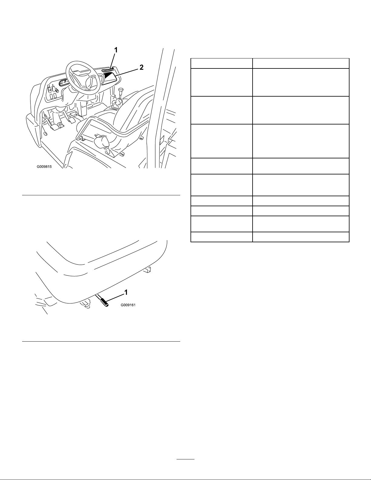
Figure1
1.Modelandserialnumberlocation
ModelNo.
Thisproductcontainsachemicalorchemicals
knowntotheStateofCaliforniatocausecancer,
birthdefects,orreproductiveharm.
Dieselengineexhaustandsomeofits
constituentsareknowntotheStateof
Californiatocausecancer,birthdefects,
andotherreproductiveharm.
Important:Theengineinthisproductisnotequipped
withasparkarrestedmufer.Itisaviolationof
CaliforniaPublicResourcecodeSection4442touse
oroperatethisengineonanyforest-covered,brush
covered,orgrass-coveredlandasdenedinCPRC4126.
Otherstatesorfederalareasmayhavesimilarlaws.
Introduction
Readthisinformationcarefullytolearnhowtooperateand
maintainyourproductproperlyandtoavoidinjuryand
productdamage.Y ouareresponsibleforoperatingthe
productproperlyandsafely.
SerialNo.
Thismanualidentiespotentialhazardsandhassafety
messagesidentiedbythesafetyalertsymbol(Figure2),
whichsignalsahazardthatmaycauseseriousinjuryordeath
ifyoudonotfollowtherecommendedprecautions.
Figure2
1.Safetyalertsymbol
Thismanualuses2otherwordstohighlightinformation.
Importantcallsattentiontospecialmechanicalinformation
andNoteemphasizesgeneralinformationworthyofspecial
attention.
YoumaycontactTorodirectlyatwww .Toro.comforproduct
andaccessoryinformation,helpndingadealer,ortoregister
yourproduct.
Wheneveryouneedservice,genuineT oroparts,oradditional
information,contactanAuthorizedServiceDealerorToro
CustomerServiceandhavethemodelandserialnumbersof
yourproductready.Figure1identiesthelocationofthe
modelandserialnumbersontheproduct.Writethenumbers
inthespaceprovided.
©2013—TheToro®Company
8111LyndaleAvenueSouth
Bloomington,MN55420
Contactusatwww.Toro.com.
2
PrintedintheUSA
AllRightsReserved
Page 3

Contents
Introduction..................................................................2
Safety...........................................................................4
SafeOperatingPractices...........................................4
Supervisor’sResponsibilities.....................................4
BeforeOperating....................................................4
Operation...............................................................5
Maintenance...........................................................6
SoundPressure.......................................................6
Vibration................................................................6
SafetyandInstructionalDecals.................................7
Setup...........................................................................12
1InstallingtheSteeringWheel(TCmodels
only).................................................................12
2InstallingtheROPS(TCmodelsonly)......................12
3ActivatingandChargingtheBattery(TCmodels
only).................................................................13
4CheckingFluidLevels...........................................14
ProductOverview.........................................................15
Controls...............................................................15
Specications........................................................18
Attachments/Accessories........................................18
Operation....................................................................19
CheckingtheEngineOilLevel.................................19
AddingFuel...........................................................19
CheckingtheCoolantLevel.....................................21
CheckingtheTransaxle/HydraulicFluid
Level.................................................................22
CheckingtheHighFlowHydraulicFluid(TC
modelsonly)......................................................22
CheckingtheFrontDifferentialOilLevel
(Four-wheeldrivemodelsonly).............................23
CheckingtheTorqueoftheWheelNuts.....................23
CheckingtheTirePressure......................................23
CheckingtheBrakeFluid.........................................23
Pre–startingChecks................................................24
StartingtheEngine.................................................24
DrivingtheVehicle.................................................24
StoppingtheVehicle...............................................25
StoppingtheEngine...............................................25
NewVehicleBreak–in.............................................25
CheckingtheInterlockSystem.................................25
OperatingCharacteristics........................................25
Passengers.............................................................26
Speed....................................................................27
Turning.................................................................27
Braking.................................................................27
TipOvers..............................................................27
Hills......................................................................27
LoadingandDumping............................................28
UsingTheDifferentialLock....................................28
FourWheelDrive(Four-wheeldrivemodels
only).................................................................29
TransportingtheVehicle.........................................29
TowingtheVehicle.................................................29
TowingaTrailerwiththeVehicle..............................30
HydraulicControl...................................................30
Maintenance.................................................................32
RecommendedMaintenanceSchedule(s)......................32
HeavyDutyOperation............................................33
PremaintenanceProcedures........................................34
UsingtheBedSafetySupport...................................34
RemovingtheFullBed............................................34
InstallingtheFullBed.............................................35
JackingtheVehicle..................................................36
RemovingtheHood...............................................36
Lubrication...............................................................37
GreasingBearingsandBushings...............................37
EngineMaintenance..................................................39
ServicingtheAirCleaner.........................................39
ChangingtheEngineOilAndFilter..........................39
FuelSystemMaintenance...........................................40
FuelLinesandConnections.....................................40
ServicingtheW aterSeparator/FuelFilter...................40
ElectricalSystemMaintenance....................................41
Fuses....................................................................41
JumpStartingtheVehicle.........................................42
ServicingtheBattery...............................................42
DriveSystemMaintenance.........................................43
ChangingtheFrontDifferentialOil(Four-wheel
drivemodelsonly)...............................................43
InspectingtheConstantVelocityBoot(Four-wheel
drivemodelsonly)...............................................43
AdjustingtheShiftCables........................................44
AdjustingtheHigh–LowCable................................44
AdjustingDifferentialLockCable.............................44
InspectingtheTires................................................44
CheckingtheFrontWheelAlignment........................45
CoolingSystemMaintenance......................................46
RemovingDebrisfromtheCoolingSystem................46
ChangingEngineCoolant........................................46
BrakeMaintenance....................................................48
AdjustingtheParkingBrake.....................................48
AdjustingtheBrakePedal........................................48
BeltMaintenance......................................................49
AdjustingBelts.......................................................49
ControlsSystemMaintenance.....................................49
AdjustingtheAcceleratorPedal................................49
AdjustingtheClutchPedal.......................................49
ConvertingtheSpeedometer....................................50
HydraulicSystemMaintenance....................................51
ChangingtheHydraulicFluidandCleaningthe
Strainer..............................................................51
ReplacingtheHydraulicFilter..................................51
ChangingtheHighFlowHydraulicOilandFilter
(TCmodelsonly)................................................52
RaisingtheBoxinanEmergency..............................52
Storage........................................................................54
Schematics...................................................................55
3
Page 4

Safety
ThemachinemeetstherequirementsofSAEJ2258.
Supervisors,operatorsandservicepersonsshouldbefamiliar
withthefollowingstandardsandpublications:(Thematerial
maybeobtainedfromtheaddressshown).
•FlammableandCombustibleLiquidsCode:
ANSI/NFPA30
•NationalFireProtectionAssociation:
ANSI/NFPA#505;PoweredIndustrialTrucks
ADDRESS:
NationalFirePreventionAssociation
BatterymarchPark
Quincy,Massachusetts02169U.S.A
•ANSI/ASMEB56.8PersonalBurdenCarriers
ADDRESS:
AmericanNationalStandardsInstitute,Inc.
25W est43rdStreet
NewYork,NewYork10036U .S.A.
•ANSI/UL558;InternalCombustionEnginePowered
IndustrialTrucks
ADDRESS:
AmericanNationalStandardsInstitute,Inc.
25W est43rdStreet
NewYork,NewYork10036U .S.A.
or
UnderwritersLaboratories
333PngstenRoad
Northbrook,Illinois60062U.S.A.
SafeOperatingPractices
WARNING
TheWorkmanisanoff–highwayvehicleonly,and
isnotdesigned,equipped,ormanufacturedforuse
onpublicstreets,roadsorhighways.
NotalloftheattachmentsthatadapttotheWorkman
arecoveredinthismanual.SeethespecicOperator’ s
Manualprovidedwitheachattachmentforadditionalsafety
instructions.Readthesemanuals.
Toreducethepotentialforinjuryordeath,complywith
thefollowingsafetyinstructions:
Supervisor’sResponsibilities
•Makesureoperatorsarethoroughlytrainedandfamiliar
withtheOperator’sManualandalllabelsonthevehicle.
•Besuretoestablishyourownspecialproceduresand
workrulesforunusualoperatingconditions(e.g.slopes
toosteepforvehicleoperation).Usethe3rdHigh
Lockoutswitchifhighspeedcouldresultinasafetyor
vehicleabusesituation.
BeforeOperating
•Operatethemachineonlyafterreadingandunderstanding
thecontentsofthismanual.Areplacementmanualis
availablebysendingcompletemodelandserialnumber
to:TheToroCompany,8111LyndaleAvenueSouth,
Minneapolis,Minnesota55420.
•Neverallowchildrentooperatethevehicle.Never
allowadultstooperateitwithoutproperinstructions.
Onlytrainedandauthorizedpersonsshouldoperate
thisvehicle.Makesurealloperatorsarephysicallyand
mentallycapableofoperatingthevehicle.
•Thisvehicleisdesignedtocarryonlyyou,theoperator,
andonepassengerintheseatprovidedbythe
manufacturer.Nevercarryanyotherpassengersonthe
vehicle.
•Neveroperatethevehiclewhenundertheinuenceof
drugsoralcohol.
•Becomefamiliarwiththecontrolsandknowhowtostop
theenginequickly .
•Keepallshields,safetydevicesanddecalsinplace.Ifa
shield,safetydeviceordecalismalfunctioning,illegible,
ordamaged,repairorreplaceitbeforeoperatingthe
machine.
TheWorkmanwasdesignedandtestedtooffersafeservice
whenoperatedandmaintainedproperly.Althoughhazard
controlandaccidentpreventionpartiallyaredependent
uponthedesignandcongurationofthemachine,these
factorsarealsodependentupontheawareness,concern,and
propertrainingofthepersonnelinvolvedintheoperation,
maintenanceandstorageofthemachine.Improperuseor
maintenanceofthemachinecanresultininjuryordeath.
Thisisaspecializedutilityvehicledesignedforoff–roaduse
only.Itsrideandhandlingwillhaveadifferentfeelthanwhat
driversexperiencewithpassengercarsortrucks.Sotaketime
tobecomefamiliarwithyourW orkman.
•Alwayswearsubstantialshoes.Donotoperatethe
machinewhilewearingsandals,tennisshoes,orsneakers.
Donotwearloosettingclothingorjewelrywhichcould
getcaughtinmovingpartsandcausepersonalinjury.
•Wearingsafetyglasses,safetyshoes,longpants,anda
helmetisadvisableandrequiredbysomelocalsafetyand
insuranceregulations.
•Keepeveryone,especiallychildrenandpets,awayfrom
theareasofoperation.
•Beforeoperatingthevehicle,alwayscheckallpartsof
thevehicleandanyattachments.Ifsomethingiswrong,
4
Page 5

stopusingvehicle.Makesuretheproblemiscorrected
beforevehicleorattachmentisoperatedagain.
•Sincedieselfuelishighlyammable,handleitcarefully.
–Useanapprovedfuelcontainer.
–Donotremovethecapfromthefueltankwhenthe
engineishotorrunning.
–Donotsmokewhilehandlingfuel.
–Fillthefueltankoutdoorsandtoaboutoneinch
belowthetopoftank(bottomofllerneck).Donot
overll.
–Wipeupanyspilledfuel.
•Operatethevehicleonlyoutdoorsorinawellventilated
area.
•Useonlyanapprovednonmetal,portablefuelcontainer.
Staticelectricdischargecanignitefuelvaporsina
ungroundedfuelcontainer.Removethefuelcontainer
fromthebedofthevehicleandplaceitontheground
awayfromthevehiclebeforelling.Keepthenozzle
incontactwiththecontainerwhilelling.Remove
equipmentfromvehiclebedbeforelling.
•Checkthesafetyinterlocksystemdailyforproper
operation.Ifaswitchshouldmalfunction,replacethe
switchbeforeoperatingmachine.Aftereverytwoyears,
replacetheinterlockswitchesinthesafetysystem,
whethertheyareworkingproperlyornot.
Operation
•Theoperatorandpassengermustuseseatbeltsand
remainseatedwheneverthevehicleisinmotion.The
operatorshouldkeepbothhandsonthesteeringwheel,
wheneverpossible,andthepassengershouldusethehand
holdsprovided.Keeparmsandlegswithinthevehicle
bodyatalltimes.Nevercarrypassengersintheboxor
onattachments.Rememberyourpassengermaynotbe
expectingyoutobrakeorturnandmaynotbeready.
•Neveroverloadyourvehicle.Thenameplate(located
underthemiddleofthedash)showstheloadlimitsfor
thevehicle.Neveroverllattachmentsorexceedthe
vehiclemaximumgrossvehicleweight(GVW).
•Whenstartingtheengine:
–Sitonoperator’sseatandensurethattheparking
brakeisengaged.
–DisengagePTO(ifsoequipped)andreturnthehand
throttlelevertotheOffposition(ifsoequipped).
–Makesurethehydraulicliftleverisinthecenter
position.
–MoveshiftlevertoNeutralandpresstheclutchpedal.
–Keepyourfootoffoftheacceleratorpedal.
–TurnignitionswitchtotheOnposition.Whenthe
glowplugindicatorgoesoff,theengineisreadyto
start.
–TurntheignitionkeytotheStartposition.
Note:Theglowplugindicatorwillturnon,foran
additional15seconds,whentheswitchreturnstothe
Startposition.
•Usingthemachinedemandsattention.Failuretooperate
vehiclesafelymayresultinanaccident,tipoverofthe
vehicle,andseriousinjuryordeath.Drivecarefully .To
preventtippingorlossofcontrol,takethefollowing
precautions:
–Useextremecaution,reducespeed,andmaintain
asafedistancearoundsandtraps,ditches,creeks,
ramps,anyunfamiliarareas,orotherhazards.
–Watchforholesorotherhiddenhazards.
–Usecautionwhenoperatingthevehicleonasteep
slope.Normally,travelstraightupanddownslopes.
Reducespeedwhenmakingsharpturnsorwhen
turningonhillsides.Avoidturningonhillsides
wheneverpossible.
–Useextracautionwhenoperatingthevehicleon
wetsurfaces,athigherspeeds,orwithafullload.
Stoppingtimewillincreasewithafullload.Shiftinto
alowergearbeforestartingupordownahill.
–Whenloadingthebed,distributetheloadevenly.
Useextracautioniftheloadexceedsthedimensions
ofthevehicle/bed.Operatethevehiclewithextra
cautionwhenhandlingoff-centerloadsthatcannot
becentered.Keeploadsbalancedandsecureto
preventthemfromshifting.
–Avoidsuddenstopsandstarts.Donotgofrom
reversetoforwardorforwardtoreversewithoutrst
comingtoacompletestop.
–Donotattemptsharpturnsorabruptmaneuversor
otherunsafedrivingactionsthatmaycausealossof
vehiclecontrol.
–Donotpassanothervehicletravelinginthesame
directionatintersections,blindspots,oratother
dangerouslocations.
–Whendumping,donotletanyonestandbehind
vehicleanddonotdumptheloadonanyone’ sfeet.
Releasethetailgatelatchesfromthesideofbox,not
frombehind.
–Keepallbystandersaway.Beforebackingup,lookto
therearandensurethatnooneisbehindthevehicle.
Backupslowly .
–Watchoutfortrafcwhennearorcrossingroads.
Alwaysyieldtherightofwaytopedestriansandother
vehicles.Thisvehicleisnotdesignedforuseon
streetsorhighways.Alwayssignalyourturnsorstop
earlyenoughsootherpersonsknowwhatyouplanto
do.Obeyalltrafcrulesandregulations.
–Neveroperatethevehicleinornearanareawhere
thereisdustorfumesintheairwhichareexplosive.
Theelectricalandexhaustsystemsofthevehiclecan
producesparkscapableofignitingexplosivematerials.
–Alwayswatchoutforandavoidlowoverhangssuch
astreelimbs,doorjambs,overheadwalkways,etc.
5
Page 6

Makesurethereisenoughroomoverheadtoeasily
clearthevehicleandyourhead.
–Ifeverunsureaboutsafeoperation,stopworkand
askyoursupervisor.
•Donottouchengine,transaxle,radiator,muferor
mufermanifoldwhileengineisrunningorsoonafter
ithasstoppedbecausetheseareasmaybehotenough
tocauseburns.
•Ifthemachineevervibratesabnormally,stopimmediately ,
turnengineoff,waitforallmotiontostopandinspectfor
damage.Repairalldamagebeforeresumingoperation.
•Beforegettingofftheseat:
–Stopmovementofthemachine.
–Lowerbed.
–Shutengineoffandwaitforallmovementtostop.
–Setparkingbrake.
–Removekeyfromignition.
•Lightningcancausesevereinjuryordeath.Iflightning
isseenorthunderisheardinthearea,donotoperate
themachine;seekshelter.
•Iftheenginemustberunningtoperformamaintenance
adjustment,keephands,feet,clothing,andanypartsof
thebodyawayfromtheengineandanymovingparts.
Keepeveryoneaway.
•Donotoverspeedtheenginebychangingthegovernor
settings.Themaximumenginespeedis3650RPM.To
ensuresafetyandaccuracy ,haveanAuthorizedToro
Distributorcheckthemaximumenginespeedwitha
tachometer.
•Ifmajorrepairsareeverneededorassistanceisrequired,
contactanAuthorizedT oroDistributor.
•Tobesureofoptimumperformanceandsafety ,
alwayspurchasegenuineTororeplacementpartsand
accessories.Replacementpartsandaccessoriesmadeby
othermanufacturerscouldbedangerous.Alteringthis
vehicleinanymannermayaffectthevehicle’soperation,
performance,durabilityoritsusemayresultininjuryor
death.SuchusecouldvoidtheproductwarrantyofThe
Toro®Company.
•ThisvehicleshouldnotbemodiedwithoutThe
Toro®Company’sauthorization.Directanyinquiries
toTheT oro®Company ,CommercialDivision,V ehicle
EngineeringDept.,8111LyndaleAve.So.,Bloomington,
Minnesota55420–1196.USA
Maintenance
•Beforeservicingormakingadjustmentstothemachine,
stoptheengine,settheparkingbrake,andremovethekey
fromignitiontopreventaccidentalstartingoftheengine.
•Neverworkunderaraisedbedwithoutplacingthebed
safetysupportonthefullyextendedcylinderrod.
•Makesureallhydrauliclineconnectorsaretight,andall
hydraulichosesandlinesareingoodconditionbefore
applyingpressuretothesystem.
•Keepyourbodyandhandsawayfrompinholeleaksor
nozzlesthatejecthydraulicuidunderhighpressure.
Usepaperorcardboard,nothands,tosearchfor
leaks.Hydraulicuidescapingunderpressurecanhave
sufcientforcetopenetrateskinanddoseriousdamage.
Ifuidisinjectedintotheskinitmustbesurgically
removedwithinafewhoursbyadoctorfamiliarwiththis
formofinjuryorgangrenemayresult.
•Beforedisconnectingorperforminganyworkonthe
hydraulicsystem,allpressureinthesystemmustbe
relievedbystoppingtheengine,cyclingthedumpvalve
fromraisetolowerand/orloweringboxandattachments.
Placetheremotehydraulicsleverintheoatposition.
Iftheboxmustbeinraisedposition,secureitwiththe
safetysupport.
•Tomakesuretheentiremachineisingoodcondition,
keepallnuts,bolts,andscrewsproperlytightened.
SoundPressure
Thisunithasasoundpressurelevelattheoperator’searof82
dBA,whichincludesanUncertaintyValue(K)of1dBA.
Thesoundpressurelevelwasdeterminedaccordingtothe
proceduresoutlinedinENISO11201.
Vibration
Hand-Arm
•Measuredvibrationlevelforrighthand=0.41m/s
•Measuredvibrationlevelforlefthand=0.2m/s
•UncertaintyValue(K)=0.5m/s
Measuredvaluesweredeterminedaccordingtotheprocedures
outlinedinEN1032.
2
WholeBody
•Measuredvibrationlevel=0.3m/s
•UncertaintyValue(K)=0.5m/s
Measuredvaluesweredeterminedaccordingtotheprocedures
outlinedinEN1032.
2
2
2
2
•Toreducethepotentialrehazard,keeptheenginearea
freeofexcessivegrease,grass,leaves,andaccumulation
ofdirt.
6
Page 7
SafetyandInstructionalDecals
Safetydecalsandinstructionsareeasilyvisibletotheoperatorandarelocatednearanyareaofpotential
danger.Replaceanydecalthatisdamagedorlost.
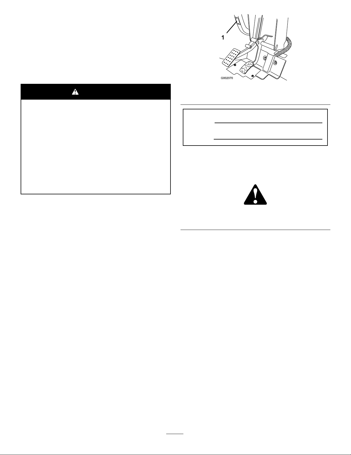
93-9852
1.Warning—readtheOperator’sManual.2.Crushinghazard—installthecylinderlock.
115-7739
1.Falling,crushinghazard,bystanders—noriderson
machine.
1.Headlights4.Engine—run
2.Horn5.Engine—start
3.Engine—stop
115-2047
1.Warning—donottouchthehotsurface.
115-2281
1.Liftpoint
93-9084
2.Tie-downpoint
7
Page 8
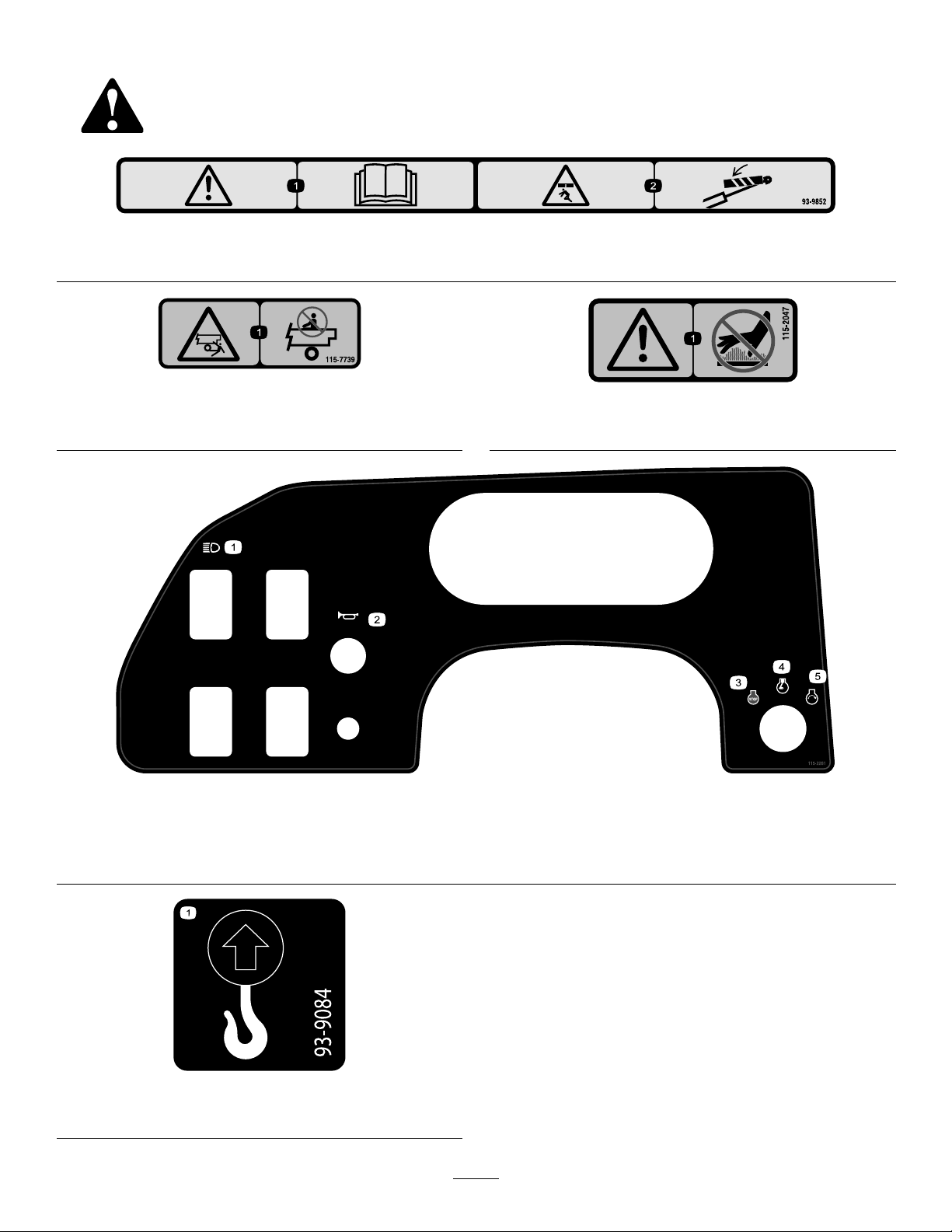
115-7723
1.Warning—thehydraulicoilpressureis124bar(1800PSI).
2.CouplerA
3.CouplerB
115-7740
1.Warning—maximumtrailerweightis1500lb(680kg),
maximumtongueweightis200lb(90kg).
2.Warning—trailerbrakesarerequiredwhentowinggreater
than1500lb(680kg),maximumtrailerweightwithtrailer
brakesis3500lb(1591kg),maximumtongueweightwith
trailerbrakesis600lb(273kg).
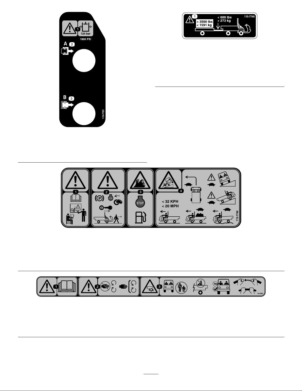
115-7746
1.Warning—donotoperatethismachineunlessyouaretrained.
2.Warning—locktheparkingbrake,stoptheengine,and
removetheignitionkeybeforeleavingthemachine.
3.Firehazard—stoptheenginebeforefueling.
4.Tippinghazard—slowdownandturngradually,usecaution
anddriveslowlywhendrivingonslopes,donotexceed20
mph(32kph),anddriveslowlyoverroughterrainorwhen
carryingafullorheavyload.
115-2282
1.Warning—readtheOperator'sManual.
2.Warning—stayawayfrommovingparts,keepallguardsandshieldsinplace.
3.Crushing/dismembermenthazardofbystanders—keepbystandersasafedistancefromthevehicle,donotcarrypassengersin
thecargobed,keeparmsandlegsinsideofthevehicleatalltimes,anduseseatbeltsandhandholds.
8
Page 9
93-7814
1.Entanglementhazard,belt—stayawayfrommovingparts.
93–9868
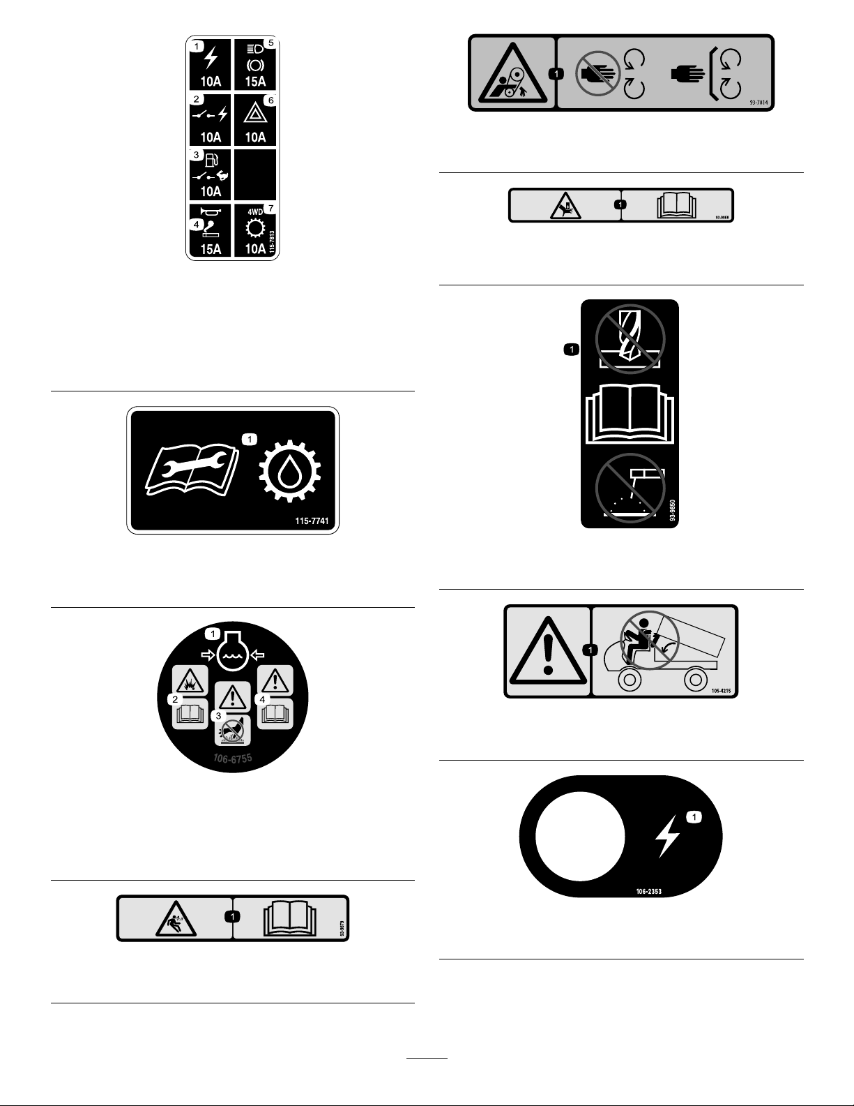
115-7813
1.Poweroutlet10A5.Lights,brake15A
2.Switchedpower10A
3.Fuelpump,supervisor
switch10A
4.Horn,powerpoint15A
6.Hazard10A
7.4WD,Transmission10A
115-7741
1.ReadtheOperator’sManualbeforeservicingtransmission
uid.
1.Crushinghazardofhand—readtheOperator’sManual.
93-9850
1.Donotrepairorrevise—readtheOperator'sManual.
106-6755
1.Enginecoolantunder
pressure.
2.Explosionhazard—read
theOperator'sManual.
3.Warning—donottouchthe
hotsurface.
4.Warning—readthe
Operator'sManual.
93-9879
1.Storedenergyhazard—readtheOperator'sManual.
105-4215
1.Warning—avoidpinchpoints.
106-2353
1.Electricalpowerpoint
9
Page 10
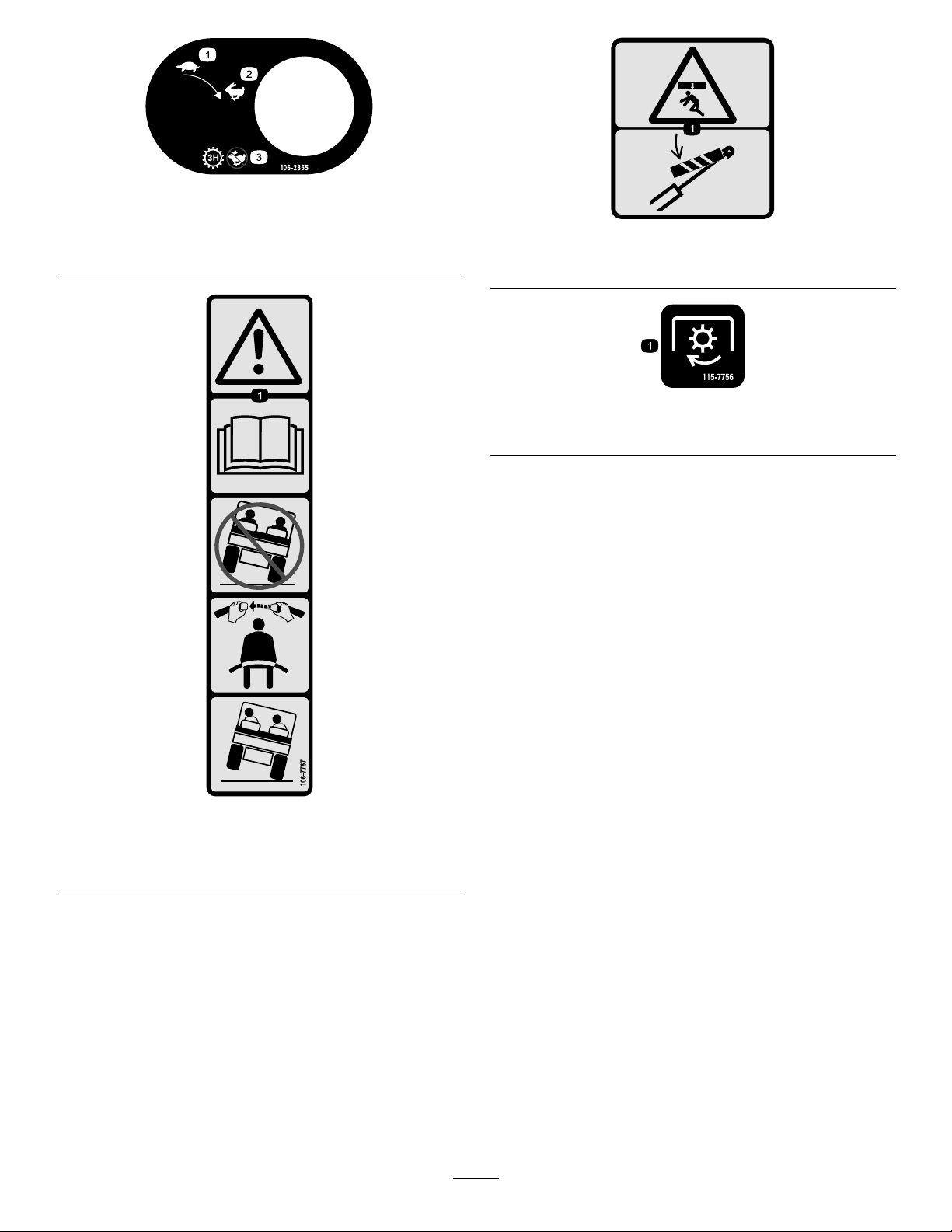
106-2355
93-9899
1.Slow
2.Fast
3.Transmission—thirdhigh;
nofastspeed
93-9899
1.Crushinghazard—installthecylinderlock.
115-7756
1.Highowhydraulics—engaged
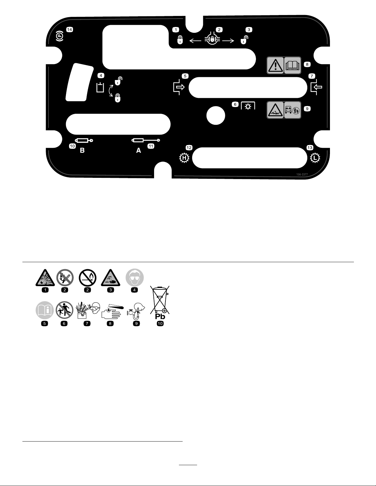
106-7767
1.Warning—readtheOperator'sManual;avoidtippingthe
machine;weartheseatbelt;leanawayfromthedirection
themachineistipping.
10
Page 11
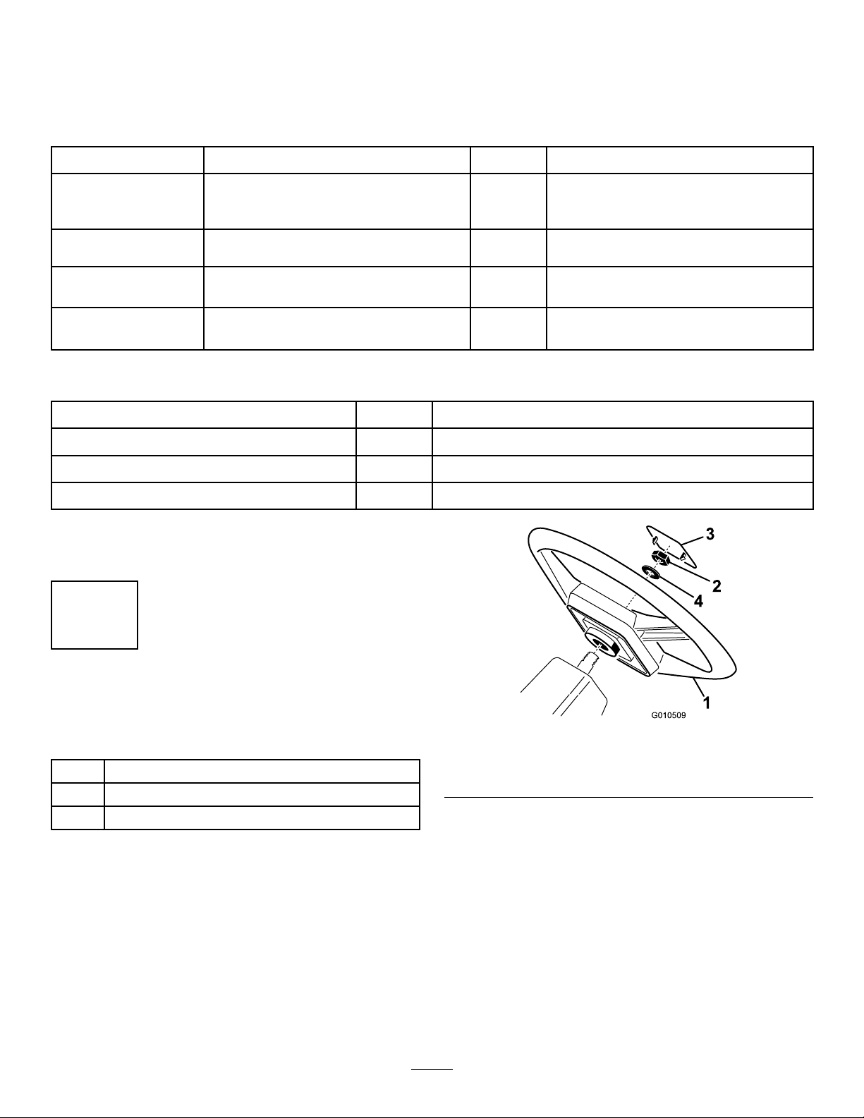
106-2377
1.Locked
2.Differentiallock9.Entanglementhazard,shaft—keepbystander'sasafe
3.Unlocked10.Retracthydraulics
4.Hydrauliclock11.Extendhydraulics
5.Engage12.Transmission—highspeed
6.Powertake-off(PTO)
7.Disengage14.Parkingbrake
8.Warning—readtheOperator'sManual.
distancefromthevehicle.
13.Transmission—lowspeed
BatterySymbols
Someorallofthesesymbolsareonyourbattery
1.Explosionhazard
2.Nore,opename,or
smoking.
3.Causticliquid/chemical
burnhazard
4.Weareyeprotection9.Flusheyesimmediately
5.ReadtheOperator's
Manual.
6.Keepbystandersasafe
distancefromthebattery.
7.Weareyeprotection;
explosivegasescan
causeblindnessandother
injuries
8.Batteryacidcancause
blindnessorsevereburns.
withwaterandgetmedical
helpfast.
10.Containslead;donot
discard.
11
Page 12
Setup
LooseParts
Usethechartbelowtoverifythatallpartshavebeenshipped.
ProcedureDescription
Steeringwheel
1
2
3
4
Cap
Washer1
ROPSframe
Bolt,1/2inch
Electrolyte
Nopartsrequired
MediaandAdditionalParts
Description
Operator'sManual
PartsManual1
OperatorTrainingMaterial
Note:Determinetheleftandrightsideofthemachinefrom
thenormaloperatingposition.
Qty.
Qty.
1
1
1
6
A/R
–
1
1
Readbeforeoperatingthevehicle
Usetoreferencepartnumbers
Viewbeforeoperatingmachine
Installthesteeringwheel.
MounttheROPS(RolloverProtection
System).
Activateandchargethebattery.
Checktheengineoil,transaxle/hydraulic
uid,andbrakeuidlevels.
Use
Use
1
InstallingtheSteeringWheel (TCmodelsonly)
Partsneededforthisprocedure:
1
Steeringwheel
1
Cap
1Washer
Procedure
1.Removethenutfromthesteeringshaft.Slidethe
steeringwheel,andwasherontothesteeringshaft
(
Figure3).
2.Securethesteeringwheeltotheshaftwiththenutand
tightenitto27–34N-m(20-25ft-lb).
3.Installthecaponthesteeringwheel.
Figure3
1.Steeringwheel3.Cap
2.Jamnut4.Washer
12
Page 13
charged.Bulkelectrolytewith1.260specicgravitycanbe
purchasedfromalocalbatterysupplyoutlet.
2
InstallingtheROPS
(TCmodelsonly)
Partsneededforthisprocedure:
1
ROPSframe
6
Bolt,1/2inch
Procedure
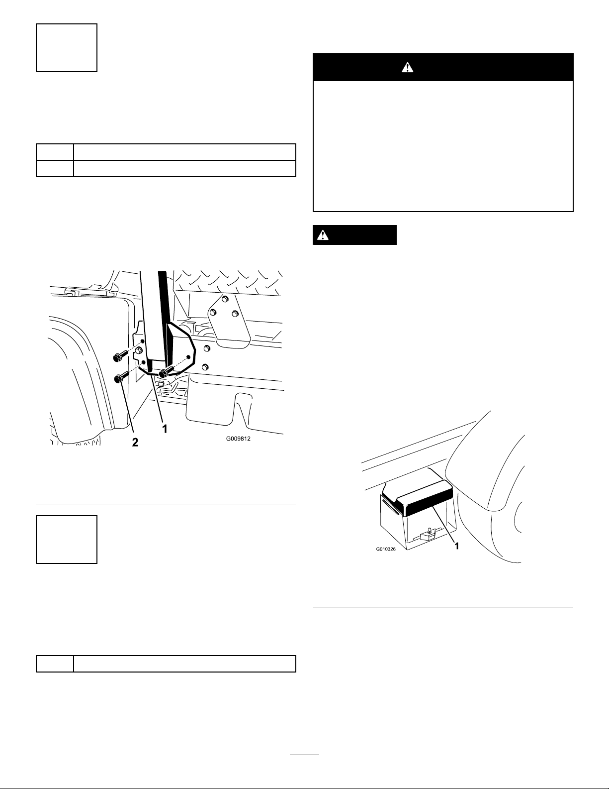
1.AligneachsideoftheROPSwiththemountingholes
oneachsideofthevehicleframeasshownin
2.SecureeachsideoftheROPStoframewith3bolts
(1/2inch)andtightenthemto115N-m(85ft-lb).
WARNING
CALIFORNIA
Proposition65Warning
Batteryposts,terminals,andrelated
accessoriescontainleadandleadcompounds,
chemicalsknowntotheStateofCalifornia
tocausecancerandreproductiveharm.
Washhandsafterhandling.
Figure4.
DANGER
Batteryelectrolytecontainssulfuricacidwhichisa
deadlypoisonandcausessevereburns.
•Donotdrinkelectrolyteandavoidcontactwith
skin,eyesorclothing.Wearsafetyglassesto
shieldyoureyesandrubberglovestoprotect
yourhands.
•Fillthebatterywherecleanwaterisalways
availableforushingtheskin.
Figure4
1.ROPS3.ROPScoverplate
2.Mountingbracket
3
ActivatingandCharging theBattery (TCmodelsonly)
Partsneededforthisprocedure:
A/R
Procedure
Electrolyte
1.Removethebatterycoverfromthebatterycase
(Figure5).
Figure5
1.Batterycover
2.Removethebatteryfromthebatterycase.
3.Removethellercapsfromthebatteryandslowlyll
eachcelluntilelectrolyteisjustabovetheplates.
4.Replacethellercapsandconnecta3to4ampbattery
chargertothebatteryposts.Chargethebatteryata
rateof3to4amperesfor4to8hours.
Ifthebatteryisnotlledwithelectrolyteoractivated,it
mustberemovedfromthevehicle,lledwithelectrolyteand
13
Page 14
WARNING
Chargingthebatteryproducesgassesthatcan
explode.
4
Neversmokenearthebatteryandkeepsparks
andamesawayfrombattery.
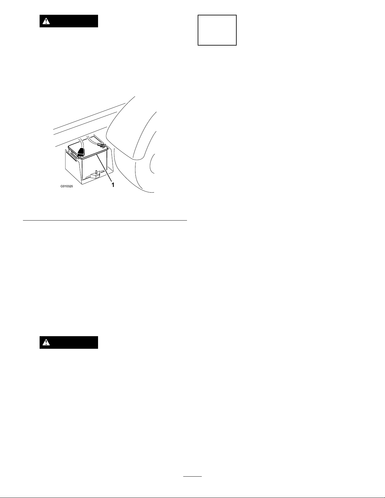
5.Whenthebatteryischarged,disconnectthecharger
fromtheelectricaloutletandbatteryposts(Figure6).
Figure6
1.Battery
6.Removethellercaps.Slowlyaddelectrolytetoeach
celluntillevelisuptothellring.Installthellercaps.
CheckingFluidLevels
NoPartsRequired
Procedure
1.Checktheengineoillevelbeforeand
aftertheengineisrststarted,referto
CheckingtheEngineOilLevel(page19).
2.Checkthetransaxle/hydraulicuidlevel
beforetheengineisrststarted,referto
CheckingtheTransaxle/HydraulicFluidLevel(page22).
3.Checkthebrakeuidlevelbeforetheengineisrst
started,refertoCheckingtheBrakeFluid(page23).
Important:Donotoverllthebattery.Electrolyte
willoverowontootherpartsofthevehicleand
severecorrosionanddeteriorationwillresult.
7.Insertthebatteryintothebatterycasesothebattery
terminalsaretowardtheoutsideofthevehicle.
8.Installthepositivecable(red)tothepositive(+)
terminalandthenegativecable(black)tothenegative
(–)terminalofthebatteryandsecurethenwithbolts
andnuts.Slidetherubberbootoverthepositive
terminaltopreventapossibleshort-outfromoccurring.
WARNING
Incorrectbatterycableroutingcoulddamage
themachineandcablescausingsparks.
Sparkscancausethebatterygassesto
explode,resultinginpersonalinjury.
•Alwaysdisconnectthenegative(black)
batterycablebeforedisconnectingthe
positive(red)cable.
•Alwaysconnectthepositive(red)battery
cable
9.Installthebatterycoveronthebatterycase.
14
Page 15

ProductOverview
Controls
Note:Determinetheleftandrightsidesofthemachine
fromthenormaloperatingposition.
AcceleratorPedal
Theacceleratorpedal(Figure7)givestheoperatortheability
tovarytheengineandgroundspeedofthevehicle,whenthe
transmissionisingear.Pressingthepedalincreasesengine
rpmandgroundspeed.Releasingthepedalwilldecrease
enginerpmandgroundspeedofthemachine.
Figure7
1.Acceleratorpedal3.Brakepedal
2.Clutchpedal
ClutchPedal
Theclutchpedal(Figure7)mustbefullypressedtodisengage
clutchwhenstartingtheengineorshiftingtransmissiongears.
Releasethepedalsmoothlywhenthetransmissionisingear
topreventunnecessarywearonthetransmissionandother
relatedparts.
Important:Donotridetheclutchpedalduring
operation.Theclutchpedalmustbefullyoutorthe
clutchwillslipcausingheatandwear.Neverholdthe
vehiclestoppedonahillusingtheclutchpedal.Damage
totheclutchmayoccur.
GearShiftLever
Fullypresstheclutchpedalandmovetheshiftlever(Figure8)
intothedesiredgearselection.Adiagramoftheshiftpattern
isindicatedbelow .
Figure8
Important:Donotshiftthetransaxletothereverseor
forwardgearunlessthevehicleisstandingstill.Damage
tothetransaxlemayoccur.
CAUTION
Downshiftingfromtoohighaspeedcancause
therearwheelstoskidresultinginlossofvehicle
controlaswellasclutchand/ortransmission
damage.Shiftsmoothlytoavoidgrindinggears.
DifferentialLock
Thedifferentiallockallowsrearaxletobelockedforincreased
traction.Thedifferentiallock(Figure9)maybeengaged
whenthevehicleisinmotion.Movetheleverforwardandto
therighttoengagethelock.
Note:V ehiclemotionplusaslightturnisrequiredtoengage
ordisengagedifferentiallock.
CAUTION
Turningwiththedifferentiallockoncanresult
inlossofvehiclecontrol.Donotoperatewith
differentiallockonwhenmakingsharpturnsorat
highspeeds.Refertousingthedifferentiallock.
BrakePedal
Thebrakepedal(Figure7)isusedtoapplyservicebrakes
tostoporslowvehicle.
CAUTION
Wornormaladjustedbrakesmayresultinpersonal
injury.Ifthebrakepedaltravelstowithin3.8cm
(1-1/2inches)ofthevehicleoorboard,thebrakes
mustbeadjustedorrepaired.
15
Page 16
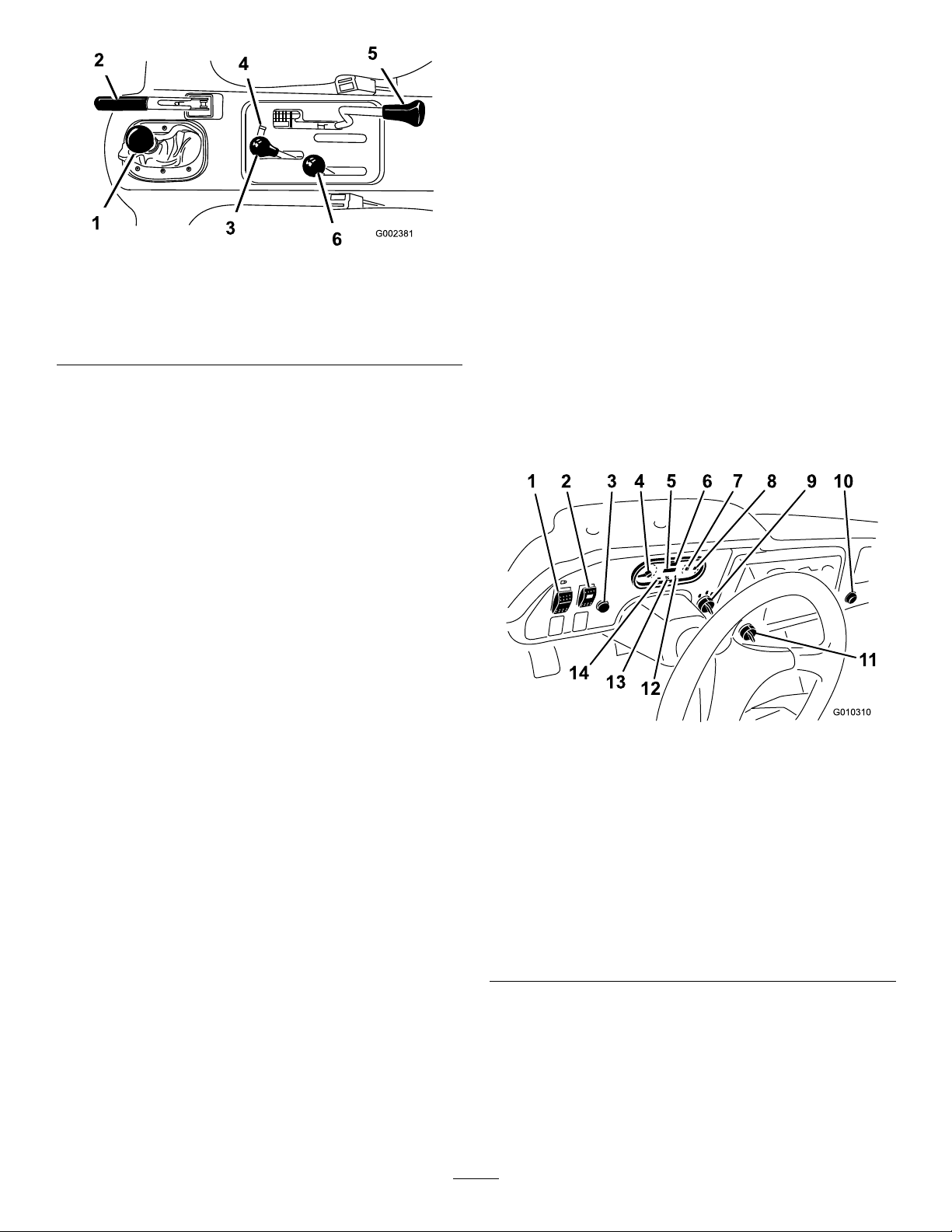
Figure9
Highisforhigherspeeddrivingonlevel,drysurfaceswith
lightloads.
Lowisforlowspeeddriving.Usethisrangewhengreater
thannormalpowerorcontrolisrequired.Forexample,steep
grades,difcultterrain,heavyloads,slowspeedbuthigh
enginespeed(spraying).
Important:ThereisalocationbetweenHighandLow
inwhichthetransaxleisinneitherrange.Donotuse
thispositionasaneutralpositionbecausethevehicle
couldmoveunexpectedlyiftheHigh–Lowshifteris
bumpedandthegearshiftleverisingear.
1.Gearshiftlever4.Hydraulicliftlock
2.Parkingbrake
3.Hydraulicbedlift6.High–lowrangeshifter
5.Differentiallock
ParkingBrake
Whenevertheengineisshutoff,theparkingbrake(Figure9)
mustbeengagedtopreventaccidentalmovementofthe
vehicle.Toengagetheparkingbrake,pullbackonthelever.
Todisengage,pushtheleverforward.Releasetheparking
brakebeforemovingthevehicle.Ifyouparkthevehicleon
asteepgrade,applytheparking.Also,shiftthetransmission
into1stgearonauphillgradeorreverseonadownhillgrade.
Placechocksatthedownhillsideofthewheels.
HydraulicLift
Thehydraulicliftraisesandlowersbed.Moveitrearwardto
raisethebed,andforwardtolowerit(Figure9).
Important:Whenloweringthebed,holdtheleverin
theforwardpositionfor1or2secondsafterthebed
contactstheframetosecureitintheloweredposition.
Donotholdthehydraulicliftineithertheraiseorlower
position,formorethan5seconds,oncethecylinders
havereachedtheendoftheirtravel.
HydraulicLiftLock
Thehydraulicliftlocklockstheliftleversothehydraulic
cylindersdonotoperatewhenthevehicleisnotequipped
withabed(Figure9).ItalsolockstheliftleverintheOn
positionwhenusingthehydraulicsforattachments.
High–LowRangeShifter
Thehigh–lowrangeshifteraddsthreeadditionalspeedsfor
precisespeedcontrol(Figure9).
•Thevehiclemustbecompletelystoppedbeforeshifting
betweenHighandLowrange.
•Shiftonlyonlevelground.
•Pressclutchpedalfully.
•MovetheleverfullyforwardforHighandfullyrearward
forLow .
IgnitionSwitch
Usetheignitionswitch(Figure10)tostartandstopthe
engine.Ithasthreepositions:Off,On/Preheat,andStart.
RotatethekeyclockwisetotheStartpositiontoengagethe
startermotor.Releasethekeywhentheenginestarts.The
keywillmoveautomaticallytotheOnposition.Toshut
theengineoff,rotatethekeycounterclockwisetotheOff
position.
Figure10
1.Lightswitch8.Fuelgauge
2.Highow
hydraulicsswitch
(TCmodelsonly)
3.Horn
(TCmodelsonly)
4.Tachometer11.3rdhighlockoutswitch
5.Hourmeter
6.Speedometer13.Glowplugindicator
7.Coolanttemperature
gaugeandlight
9.Ignitionswitch
10.Powerpoint
12.Oilpressurewarninglight
14.Chargeindicator
HourMeter
Indicatesthetotalhoursofmachineoperation.Thehour
meter(Figure10)startstofunctionwheneverthekeyswitch
isrotatedtotheOnpositionoriftheengineisrunning.
16
Page 17
3rdHighLockoutSwitch
Movethe3rdhighlockoutswitch(Figure10)totheslow
positionandremovethekeytopreventtheuseofthirdgear
whenintheHighrange.Theenginewillshutoffiftheshift
leverismovedtothirdgearwheninHighrange.Thekeyis
removableineitherposition.
•Applyparkingbrake.
•TurntheignitionkeytotheOn/Preheatposition,butdo
notstarttheengine.Thecoolanttemperature,charge
indicator,andoilpressurelightsshouldglow.Ifanylight
doesnotfunction,eitherabulbisburnedoutorthereisa
malfunctioninthesystemwhichmustberepaired.
LightSwitch
Pushthelightswitch(Figure10)totoggletheheadlightson
oroff.
OilPressureWarningLight
Theoilpressurewarninglightglows(Figure10)iftheengine
oilpressuredropsbelowasafelevelwhiletheengineis
running.Ifthelightickersorremainson,stopthevehicle,
turnofftheengine,andchecktheoillevel.Iftheoillevelwas
low,butaddingoildoesnotcausethelighttogooutwhen
theengineisrestarted,turntheengineoffimmediatelyand
contactyourlocalT orodistributorforassistance.
Checktheoperationofwarninglightsasfollows:
1.Applytheparkingbrake.
2.TurntheignitionkeytotheOn/Preheatposition,but
donotstarttheengine.Theoilpressurelightshould
glowred.Ifthelightdoesnotfunction,eitherabulb
isburnedoutorthereisamalfunctioninthesystem
whichmustberepaired.
Note:Ifenginewasjustturnedoff,itmaytake1to2
minutesforthelighttocomeon.
FuelGauge
Thefuelgaugeshowstheamountoffuelinthetank.It
operatesonlywhenignitionswitchisintheOn/Preheat
position(Figure10).Redindicateslowfuellevelandblinking
redindicatesnearempty.
HighFlowHydraulicsSwitch(TC
modelsonly)
Turnontheswitchtoactivatethehighowhydraulics
(Figure10).
HornButton(TCmodelsonly)
Pressingthehornbuttonactivatesthehorn(Figure10).
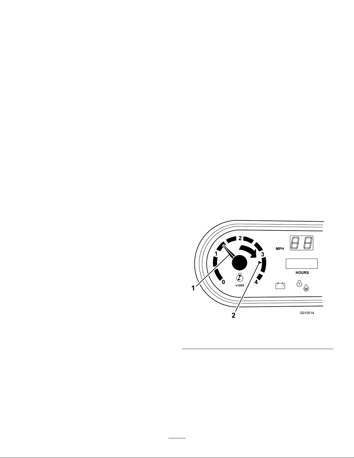
Tachometer
Registersthespeedoftheengine(Figure10&Figure11).
WhitetriangleindicatesdesiredrpmforPTOoperation
(Figure11).
GlowPlugIndicator
Glowplugindicator(Figure10)willglowredwhentheglow
plugsareactivated.
Important:Theglowplugindicatorwillturnon,foran
additional15seconds,whentheswitchreturnstothe
Startposition.
CoolantTemperatureGaugeandLight
Registersthecoolanttemperatureintheengine.Operates
onlywhentheignitionswitchisinOnposition(
Theindicatorlightwillilluminateblinkingrediftheengine
overheats.
Figure10).
ChargeIndicator
Illuminateswhenbatteryisbeingdischarged.Iflight
illuminatesduringoperation,stopvehicle,turnoffengineand
checkforpossiblecauses,suchasalternatorbelt(Figure10).
Important:Ifalternatorbeltislooseorbroken,do
notoperatethevehicleuntiladjustmentorrepairis
complete.Failuretoobservethisprecautionmayresult
indamagetotheengine.
Checktheoperationofwarninglightsasfollows:
Figure11
1.Speedoftheengine2.3,300rpmfor540rpm
PTOoperation
Speedometer
Registersthegroundspeedofthevehicle(Figure10).The
speedometerisinmphbutcaneasilyconvertedtokm/h.
RefertoConvertingtheSpeedometer(page50).
PowerPoint
Usethepowerpoint(Figure10)topoweroptional12volt
electricalaccessories.
17
Page 18
PassengerHandHold
Thepassengerhandholdislocatedonthedashboard
(Figure12).
Figure12
1.Passengerhandhold
2.Storagecompartment
SeatAdjustingLever
Theseatscanbeadjustedforeandaftforoperatorcomfort
(Figure13).
Specications
Note:Specicationsanddesignaresubjecttochange
withoutnotice.
Dimensions
OverallWidth160cm(63inches)
w/obed:326cm(128.25inches)
OverallLength
BaseWeight(Dry)
RatedCapacity
(includes91kg(200lb)
operator,91kg(200lb)
passengerandloaded
attachment).
Maximum.Gross
VehicleWeight
TowCapacityT ongueweight:272kg(600lb)
GroundClearance18cm(7inches)w/noload
WheelBase
WheelTread(center
linetocenterline)
Height
w/fullbed:331cm(130.38inches)
w/2/3bedinrearmountinglocation:
346cm(136.38inches)
Model07385—887kg(1,956lb)
Model07385TC—924kg(2,037lb)
Model07387—914kg(2,015lb)
Model07387TC—951kg(2,096lb)
Model07385—1,471kg(3,244lb)
Model07385TC—1,435kg(3,163lb)
Model07387—1,445kg(3,185lb)
Model07387TC—1,408kg(3,104lb)
2,359kg(5,200lb)
Maximumtrailerweight:1,587kg
(3,500lb)
118cm(70inches)
Front:117cm(46inches)
Rear:121cm(47.7inches)
190.5cm(75inches)totopofROPS
1.Seatadjustinglever
Attachments/Accessories
AselectionofT oroapprovedattachmentsandaccessoriesis
availableforusewiththemachinetoenhanceandexpand
itscapabilities.ContactyourAuthorizedServiceDealeror
Distributororgotowww.Toro.comforalistofallapproved
attachmentsandaccessories.
Figure13
18
Page 19

Operation
Note:Determinetheleftandrightsidesofthemachine
fromthenormaloperatingposition.
CAUTION
Beforeservicingormakingadjustmentstothe
machine,stoptheengine,settheparkingbrake,
andremovethekeyfromtheswitch.Removeany
loadmaterialfromthebedorotherattachment
beforeworkingunderaraisedbed.Neverwork
underaraisedbedwithoutpositioningthesafety
supportonafullyextendedcylinderrod.
CheckingtheEngineOilLevel
ServiceInterval:Beforeeachuseordaily
Note:Thebesttimetochecktheengineoiliswhenthe
engineiscoolbeforeithasbeenstartedfortheday.Ifithas
alreadybeenrun,allowtheoiltodrainbackdowntothe
sumpforatleast10minutesbeforechecking.Iftheoillevelis
atorbelowtheAddmarkonthedipstick,addoiltobringthe
oilleveltotheFullmark.Donotoverll.Iftheoillevelis
betweentheFullandAddmarks,noadditionaloilisrequired.
TheengineusesanyDetergentdieselengineoil(APIservice
CH-4orhigher).Chooseaviscosityaccordingtothetable
inFigure14.
Figure15
1.Fillercap
4.Installthedipstickrmlyinplace.
AddingFuel
Useonlyclean,freshdieselfuelorbiodieselfuelswithlow
(<500ppm)orultralow(<15ppm)sulfurcontent.The
minimumcetaneratingshouldbe40.Purchasefuelin
quantitiesthatcanbeusedwithin180daystoensurefuel
freshness.
Fueltankcapacity:22l(5.85gallons).
Usesummergradedieselfuel(No.2-D)attemperatures
above-7°C(20°F)andwintergrade(No.1-DorNo.
1-D/2-Dblend)belowthattemperature.Useofwintergrade
fuelatlowertemperaturesprovideslowerashpointand
coldowcharacteristicswhichwilleasestartingandreduce
fuellterplugging.
Useofsummergradefuelabove-7°C(20°F)willcontribute
towardlongerfuelpumplifeandincreasedpowercompared
towintergradefuel.
Figure14
1.Positionthemachineonalevelsurface.
2.Removethedipstickandwipeitwithacleanrag.Insert
thedipstickintothetubeandmakesureitisseated
fully.Removedipstickandchecktheleveloftheoil.
3.Iftheoillevelislow,removethellercap(
andaddenoughoiltoraisetheleveltotheFullmark
onthedipstick.
Figure15)
Important:Donotusekeroseneorgasolineinsteadof
dieselfuel.Failuretoobservethiscautionwilldamage
theengine.
WARNING
Fuelisharmfulorfatalifswallowed.Long-term
exposuretovaporscancauseseriousinjuryand
illness.
•Avoidprolongedbreathingofvapors.
•Keepyourfaceawayfromthenozzleandgas
tankorconditioneropening.
•Keepfuelawayfromyoureyesandskin.
19
Page 20

DANGER
Undercertainconditions,dieselfuelandfuel
vaporsarehighlyammableandexplosive.Are
orexplosionfromfuelcanburnyouandothersand
cancausepropertydamage.
•Beforeremovingthefueltankcap,makesure
thevehicleispositionedonalevelsurface.Open
fueltankcapslowly .
•Useafunnelandllthefueltankoutdoors,in
anopenarea,whentheengineisoffandiscold.
Wipeupanyfuelthatspills.
•Donotllthefueltankcompletelyfull.Addfuel
tothefueltankuntilthelevelis25mm(1inch)
belowthebottomofthellerneck.Thisempty
spaceinthetankallowsthefueltoexpand.
•Neversmokewhenhandlingfuel,andstayaway
fromanopenameorwherefuelfumesmaybe
ignitedbyaspark.
•Storefuelinaclean,safety-approvedcontainer
andkeepthecapinplace.
BiodieselReady
Figure16
1.Fueltankcap
3.Fillthetanktoaboutoneinchbelowthetopofthe
tank,(bottomofthellerneck),theninstallthecap.
Donotoverll.
4.Wipeupanyfuelthatmayhavespilledtopreventa
rehazard.
Thismachinecanalsouseabiodieselblendedfuelofup
toB20(20%biodiesel,80%petrodiesel).Thepetrodiesel
portionshouldbeloworultralowsulfur.Observethe
followingprecautions:
•Thebiodieselportionofthefuelmustmeetspecication
ASTMD6751orEN14214.
•TheblendedfuelcompositionshouldmeetASTMD975
orEN590.
•Paintedsurfacesmaybedamagedbybiodieselblends.
•UseB5(biodieselcontentof5%)orlesserblendsincold
weather.
•Monitorseals,hoses,gasketsincontactwithfuelasthey
maybedegradedovertime.
•Fuellterpluggingmaybeexpectedforatimeafter
convertingtobiodieselblends.
•Contactyourdistributorifyouwishformoreinformation
onbiodiesel.
1.Cleantheareaaroundthefueltankcap.
2.Removethefueltankcap(Figure16).
20
Page 21

CheckingtheCoolantLevel
1
G019522
ServiceInterval:Beforeeachuseordaily
3.Ifcoolantislow ,removethereservetankcapandadda
50/50mixtureofwaterandpermanentethyleneglycol
antifreeze.Donotoverll.
Coolingsystemcapacity:3.7l(4qt)
Thecoolingsystemislledwitha50/50solutionofwater
andpermanentethyleneglycolantifreeze.
1.Parkthemachineonalevelsurface.
CAUTION
Iftheenginehasbeenrunning,the
pressurized,hotcoolantcanescapeandcause
burns.
•Donotopentheradiatorcap.
•Allowtheenginetocoolatleast15minutes
oruntiltheradiatorcapiscoolenoughto
touchwithoutburningyourhand.
•Usearagwhenopeningthereservetank
cap,andopenthecapslowlytoallow
steamtoescape.
•Donotcheckthecoolantlevelatthe
radiator;onlycheckthecoolantlevelatthe
reservetank.
4.Installthereservetankcap.
2.Checkthecoolantlevelatthereservetank(Figure17).
Thecoolantshouldbeuptothebottomoftheller
neck.
1.Coolantreservetank
Figure17
21
Page 22

Checkingthe Transaxle/HydraulicFluid Level
ServiceInterval:Beforeeachuseordaily
ThetransaxlereservoirislledwithDexronIIIATF .Check
thelevelbeforetheengineisrststartedandevery8hoursor
daily,thereafter.Capacityofsystemis.
Transaxlereservoircapacity:7l(7.5qt).
1.Positionthevehicleonalevelsurface.
2.Cleantheareaaroundthedipstick(
Figure18).
Figure19
1.Cap
2.Removethedipstick(Figure19)fromthellerneck
andwipeitwithacleanrag.Insertthedipstickinto
thellerneck;thenremoveitandchecktheuidlevel.
Theuidlevelshouldbebetweenthetwomarkson
thedipstick.
3.Ifthelevelislow ,addtheappropriateuidto
raisetheleveltotheuppermark.Referto
ChangingtheHighFlowHydraulicOilandFilter(TCmodelsonly)(page52).
4.Installthedipstickandcapontothellerneck.
5.Starttheengineandturnontheattachment.Letthem
runforabouttwominutestopurgeairfromthesystem.
Stoptheengineandattachmentandcheckforleaks.
Figure18
1.Dipstick
3.Unscrewthedipstickfromthetopofthetransaxleand
wipeitwithacleanrag.
4.Screwthedipstickintothetransaxleandensurethat
itisfullyseated.
5.Unscrewthedipstickandchecktheuidlevel.
Theuidshouldbeuptotopoftheatportionof
thedipstick.
6.Ifthelevelislow ,addenoughuidtoachievethe
properlevel.
CheckingtheHighFlow HydraulicFluid(TCmodels only)
ServiceInterval:Beforeeachuseordaily
Thehighowhydraulicsreservoirislledwithapproximately
15l(4gallons)ofhighqualityhydraulicuid.Checkthe
levelofhydraulicuidbeforetheengineisrststarted
anddailythereafter.
1.Cleantheareaaroundthellerneckandthecapof
thehydraulictank(
thellerneck.
Figure19).Removethecapfrom
Important:Thevehiclemustberunningbefore
startingthehighowhydraulics.
WARNING
Hydraulicuidescapingunderpressurecan
penetrateskinandcauseinjury.
•Makesureallhydraulicuidhosesand
linesareingoodconditionandallhydraulic
connectionsandttingsaretightbefore
applyingpressuretothehydraulicsystem.
•Keepyourbodyandhandsawayfrom
pinholeleaksornozzlesthatejecthigh
pressurehydraulicuid.
•Usecardboardorpapertondhydraulic
leaks.
•Safelyrelieveallpressureinthehydraulic
systembeforeperforminganyworkonthe
hydraulicsystem.
•Seekimmediatemedicalattentionifuid
isinjectedintoyourskin.
22
Page 23

CheckingtheFrontDifferential
CheckingtheTirePressure
OilLevel(Four-wheeldrive
modelsonly)
ServiceInterval:Every100hours/Monthly(whichever
comesrst)
ThedifferentialislledwithMobil424hydraulicoil.
1.Positionthevehicleonalevelsurface.
2.Cleantheareaaroundthell/checkplugonsideof
thedifferential(Figure20).
ServiceInterval:Beforeeachuseordaily
Theairpressureinthefronttiresis220kPa(32psi)andthe
reartiresis124kPa(18psi).
Checkthetirepressurefrequentlytoensureproperination.
Ifthetiresarenotinatedtothecorrectpressure,thetires
willwearprematurely .
Figure21isanexampleoftirewearcausedbyunderination.
Figure21
1.Underinatedtire
Figure22isanexampleoftirewearcausedbyoverination.
Figure20
1.Fill/checkplug
3.Removethell/checkplugandcheckthelevelofthe
oil.Theoilshouldbeuptohole.Iftheoilislow ,add
Mobil424hydraulicoil.
4.Installthell/checkplug.
2.Drainplug
CheckingtheTorqueofthe WheelNuts
ServiceInterval:Aftertherst2hours
Aftertherst10hours
Every200hours
WARNING
Failuretomaintainpropertorqueofthewheelnuts
couldresultinfailureorlossofawheelandmay
resultinpersonalinjury.
Torquethefrontandrearwheelnutsto109to122
N-m(80to90ft-lb)after1to4hoursofoperation
andagainafter10hoursofoperation.Torqueevery
200hoursthereafter.
Figure22
1.Overinatedtire
CheckingtheBrakeFluid
ServiceInterval:Beforeeachuseordaily—Checkthebrake
uidlevel.
Every1,000hours/Every2years(whichevercomes
rst)—Changethebrakeuid.
Thebrakeuidreservoirisshippedfromthefactorylled
withDOT3brakeuid.Checkthelevelbeforetheengineis
rststartedandevery8hoursordaily,thereafter.
Thebrakeuidreservoirislocatedunderthedash.
1.Parkthemachineonalevelsurface.
2.TheuidlevelshouldbeuptotheFulllineonthe
reservoir(
Figure23).
23
Page 24

1.Brakeuidreservoir
Figure23
•Checkthebrakepedaloperation.
•Checktoseethatthelightsandhornareworking.
•Turnthesteeringwheeltotheleftandrighttocheckthe
steeringresponse.
•Stoptheengineandwitformovingpartstostop,then
checkforoilleaks,looseparts,andanyothernoticeable
malfunctions.
Ifanyoftheaboveitemsarenotcorrect,notifyyourmechanic
orcheckwithyoursupervisorbeforetakingthevehicleout
fortheday.Yoursupervisormaywantyoutocheckother
itemsonadailybasis,soaskwhatyourresponsibilitiesare.
StartingtheEngine
3.Iftheuidlevelislow ,cleantheareaaroundthecap,
removethereservoircap,andllthereservoirtothe
properlevel.Donotoverll.
Note:Youcanremovethehoodaccesstothereservoirfrom
thefrontofthemachine(Figure24).
Figure24
1.Sitontheoperator’sseatandengagetheparkingbrake.
2.DisengagethePTOandhighowhydraulics(ifso
equipped)andmovethehandthrottlelevertotheOff
position(ifsoequipped).
3.MovetheshiftlevertotheNeutralpositionandpress
theclutchpedal.
4.Ensurethatthehydraulicliftleverisinthecenter
position.
5.Keepyourfootoffoftheacceleratorpedal.
6.TurntheignitionswitchtotheOnposition.Whenthe
glowplugindicatorlightgoesoff,theengineisready
tostart.
7.RotatetheignitionkeyswitchtotheStartposition.
Releasethekeyimmediatelywhentheenginestartsand
allowittoreturntotheRunposition.
Note:Theglowplugindicatorwillturnonforanadditional
15seconds,whentheswitchreturnstotheRunposition.
Note:Donotrunthestartermotormorethan10secondsat
atimeorprematurestarterfailuremayresult.Ifenginefails
tostartafter10seconds,turnthekeytotheOffposition.
Checkthecontrolsandstartingprocedure,wait10additional
seconds,andrepeatthestartingoperation.
1.Brakeuidreservoir
Pre–startingChecks
Safeoperationbeginsbeforetakingthevehicleoutforaday’s
work.Youshouldchecktheseitemseachtime:
•Checkthetirepressure.
Note:Thesetiresaredifferentthancartires,theyrequire
lesspressuretominimizeturfcompactionanddamage.
•Checkalluidlevelsandaddtheappropriateamountof
Torospecieduids,ifanyarefoundtobelow .
•Checkthefrontoftheradiator.Removeanydebrisand
cleantheradiatorscreen.
DrivingtheVehicle
1.Releasetheparkingbrake.
2.Fullypresstheclutchpedal.
3.Movethegearshiftleverto1stgear.
4.Releasetheclutchpedalsmoothlywhilepressingthe
acceleratorpedal.
5.Whenthevehiclegainsenoughspeed,removeyour
footfromtheacceleratorpedal,fullypresstheclutch
pedal,movethegearshiftlevertothenextgearand
releasetheclutchpedalwhilepressingtheaccelerator
pedal.Repeattheprocedureuntilthedesiredspeedis
attained.
24
Page 25

Important:Alwaysstopthevehiclebeforeshifting
toreverseaforwardgearortoaforwardgearfrom
reverse.
Note:Avoidlongperiodsofengineidling.
Usethechartbelowtodeterminethegroundspeedof
thevehicleat3600rpm.
Gear
1L82.83:14.72.9
2L54.52:17.24.5
3L31.56:112.5
1H32.31:112.27.6
2H21.27:118.511.5
3H12.31:131.919.8
RL86.94:14.52.8
RH33.91:111.67.1
RangeRatio
Important:Donotattempttopushortowvehicle
togetitstarted.Damagetothedrivetraincould
result.
Speed
(kmh)
•Abreak–inoilfortheengineisnotrequired.The
originalengineoilisthesametypespeciedforregular
oilchanges.
•RefertotheMaintenancesectionforanyspeciallowhour
checks.
Speed
(mph)
7.7
CheckingtheInterlockSystem
ServiceInterval:Beforeeachuseordaily
Thepurposeoftheinterlocksystemistopreventtheengine
fromcrankingorstartingunlesstheclutchpedalispressed.
CAUTION
Ifsafetyinterlockswitchesaredisconnectedor
damagedthemachinecouldoperateunexpectedly
causingpersonalinjury.
•Donottamperwiththeinterlockswitches.
•Checktheoperationoftheinterlockswitches
dailyandreplaceanydamagedswitchesbefore
operatingthemachine.
Note:RefertoAttachmentOperator’sManualforprocedures
oncheckingtheattachmentinterlocksystem.
StoppingtheVehicle
Tostopthevehicle,removeyourfootfromtheaccelerator
pedal,presstheclutchpedal,thenpressthebrakepedal.
StoppingtheEngine
Tostoptheengine,rotatetheignitionkeytotheOffposition
andengagetheparkingbrake.Removethekeyfromthe
switchtopreventaccidentalstarting.
NewVehicleBreak–in
YourWorkmanisreadyforwork.Toprovideproper
performanceandlongvehiclelife,followtheseguidelinesfor
therst100operatinghours.
•Checktheuidandengineoillevelsregularlyandbealert
forindicationsofoverheatinginanycomponentofthe
vehicle.
•Afterstartingacoldengine,letitwarmupforabout15
secondsbeforeshiftingintogear.
•Avoidracingtheengine.
•Toensureoptimumperformanceofthebrakesystem,
burnish(break–in)thebrakesbeforeuse.Toburnishthe
brakes,bringthevehicleuptofullspeed,applythebrakes
torapidlystopthevehiclewithoutlockingupthetires.
Repeatthis10times,waiting1minutebetweenstopsto
avoidoverheatingthebrakes.Thisismosteffectiveifthe
vehicleisloadedwith454kg(1000lb).
•Varyvehiclespeedsduringoperation.Avoidexcessive
idling.Avoidfaststartsandquickstops.
VerifyingtheClutchInterlockSwitch
1.Sitontheoperator’sseatandengagetheparkingbrake.
MovetheshiftlevertotheNeutralposition.
Note:Theenginewillnotcrankifthehydrauliclift
leverislockedintheforwardposition.
2.Withoutpressingtheclutchpedal,rotatetheignition
keyclockwisetotheStartposition.
Iftheenginecranksorstarts,thereisamalfunction
intheinterlocksystemthatmustberepairedbefore
operatingthevehicle.
VerifyingtheHydraulicLiftLever
InterlockSwitch
1.Sitontheoperator’sseatandengagetheparkingbrake.
MovetheshiftlevertotheNeutralpositionandensure
thatthehydraulicliftleverisinthecenterposition.
2.Pressclutchpedal.
3.Movethehydraulicliftleverforwardandrotatethe
ignitionkeyclockwisetothestartposition.
Ifenginecranksorstarts,thereisamalfunctioninthe
interlocksystemthatmustberepairedbeforeoperating
vehicle.
OperatingCharacteristics
Thevehicleisdesignedwithsafetyinmind.Ithasfour
wheelsforaddedstability.Itusesfamiliarautomotivestyle
controls,includingthesteeringwheel,brakepedal,clutch
25
Page 26

pedal,acceleratorpedal,andgearshifter.Itisimportantto
remember,however,thatthisvehicleisnotapassengercar.It
isaworkvehicleandisdesignedforoffroaduseonly.
WARNING
TheWorkmanvehicleisanoff–highway
vehicleonly,andisnotdesigned,equipped,or
manufacturedforuseonpublicstreets,roadsor
highways.
Thevehiclehasspecialtires,lowgearratios,alocking
differential,andotherfeaturesthatgiveitextratraction.
Thesefeaturesaddtotheversatilityofthevehiclebut,they
canalsogetyouintodangeroussituations.Youmustkeep
inmindthatthevehicleisnotarecreationvehicle,itis
notanallterrainvehicle,and,itisdenitelynotmeantfor
stuntdrivingorhorsingaround.Itisaworkvehicle,not
aplayvehicle.Childrenshouldnotbeallowedtooperate
thevehicle.Anyonewhooperatesthevehicleshouldhavea
motorvehiclelicense.
Thedriverandpassengershouldalwaysusetheseatbelts.
Ifyouarenotexperiencedatdrivingthevehicle,practice
drivingitinasafeareaawayfromotherpeople.Besure
youarefamiliarwithallthevehicle’scontrols,particularly
thoseusedforbraking,steering,andtransmissionshifting.
Learnhowyourvehiclehandlesondifferentsurfaces.Your
operatingskillswillimprovewithexperience,butasin
operatinganyvehicle,takeiteasyasyoubegin.Besureyou
knowhowtostopquicklyinanemergency.Ifyouneedhelp,
askyoursupervisorforassistance.
Passengers
Wheneveryouhaveapassengerridinginthevehiclemake
sureheorsheiswearingtheseatbeltandholdingonsecurely.
Driveslowerandturnlesssharplybecauseyourpassenger
doesnotknowwhatyouaregoingtodonextandmaynotbe
preparedforturning,stopping,accelerating,andbumps.
Youandyourpassengershouldremainseatedatalltimes,
keepingarmsandlegsinsidethevehicle.Theoperatorshould
keepbothhandsonsteeringwheel,wheneverpossible,
andthepassengershouldusethehandholdsprovided
(
Figure25&Figure26).
Figure25
1.Passengerhandhold
2.Storagecompartment
Manyfactorscontributetoaccidents.Y ouhavecontrolover
severalofthemostimportant.Youractions,suchasdriving
toofastforconditions,brakingtoofast,turningtoosharp,
andcombinationsofthese,arefrequentcauseofaccidents.
Oneofthemajorcausesofaccidentsisfatigue.Besureto
takeoccasionalbreaks.Itisveryimportantthatyoustay
alertatalltimes.
Neveroperatethevehicle,oranyequipment,ifyouareunder
theinuenceofalcoholorotherdrugs.Evenprescription
drugsandcoldmedicinescancausedrowsiness.Readthe
labelonthemedicineorcheckwithyourdoctororpharmacist
ifyouareunsureaboutacertainmedication.
Oneofthemostimportantrulestofollowistogoslowerin
unfamiliarareas.Itissurprisinghowmuchdamageandinjury
commonthingscancause.Treebranches,fences,wires,other
vehicles,treestumps,ditches,sandtraps,streams,andother
thingsfoundinmostparksandgolfcoursescanbehazardous
totheoperatorandpassenger.
Avoiddrivingwhenitisdark,especiallyinunfamiliarareas.If
youmustdrivewhenitisdark,besuretodrivecautiously,use
theheadlights,andevenconsideraddingadditionallights.
Figure26
1.Handhold&hiprestraint
Neveralowpassengersinthedumpboxoronany
attachments.Thevehicleismeanttohaveonedriverand
onlyonepassenger—nomore.
26
Page 27

Speed
Speedisoneofthemostimportantvariablesleadingto
accidents.Drivingtoofastfortheconditionscancauseyou
tolosecontrolandhaveanaccident.Speedcanalsomakea
minoraccidentworse.Drivinghead-onintoatreeatslow
speedcancauseinjuryanddamage,but,drivingintoatree
athighspeedcandestroythevehicleandkillyouandyour
passenger.
Neverdrivetoofastfortheconditions.Ifthereisanydoubt
abouthowfasttodrive,slowdown.
Whenusingheavyattachments,morethan454kg(1000lb),
suchassprayers,topdressers,orspreaders,etc.,restrictyour
operatingspeedbymovingthe3rdhighlockoutswitchto
theslowposition.
Turning
Turningisanotherimportantvariableleadingtoaccidents.
Turningtoosharplyfortheconditionscancausethevehicle
tolosetractionandskid,oreventipover.
Wet,sandy,andslipperysurfacesmaketurningmoredifcult
andrisky.Thefasteryouaregoing,theworsethissituation
becomesso,slowdownbeforeturning.
Duringasharpturnathigherspeeds,theinsiderearwheel
mayliftoffoftheground.Thisisnotaawinthedesign,it
happenswithmostfourwheelvehiclesincludingpassenger
cars.Ifthishappens,youareturningtoosharplyforthespeed
atwhichyouaretraveling.Slowdown!
Donotdownshiftforbrakingonicyorslipperysurfaces(wet
grass)orwhilegoingdownahillbecauseenginebraking
maycauseskiddingandlossofcontrol.Shifttoalowergear
beforestartingdownahill.
TipOvers
Thevehicleisequippedwitharollbar,hiprestraints,seat
belts,andhandhold.TheROPSsystem(RolloverProtection
System)usedonthevehiclewillreducetheriskofseriousor
fatalinjuryintheunlikelyeventofatipover,althoughthe
systemcannotprotecttheoperatorfromallpossibleinjuries.
ReplaceadamagedROPS,donotrepairorrevise.Any
alterationoftheROPSmustbeapprovedbythemanufacturer.
Thebestwaytopreventaccidentsinvolvingutilityvehicles
isthroughcontinuoussupervisionandtrainingofoperators
andpayingconstantattentiontotheareainwhichvehicle
isbeingoperated.
Thebestwayforoperatorstopreventseriousinjuryordeath
tothemselvesorothers,istofamiliarizethemselveswiththe
properoperationoftheutilityvehicle,tostayalertandto
avoidactionsorconditionswhichcouldresultinaaccident.
Intheeventofatipover,theriskofseriousinjuryordeath
willbereducediftheoperatorisusingtheROPSsystemand
seatbeltsandisfollowingtheinstructionsprovided.
Hills
WARNING
Braking
Itisgoodpracticetoslowdownbeforeyougetnearan
obstacle.Thisgivesyouextratimetostoporturnaway .
Hittinganobstaclecandamagethevehicleanditscontents.
Moreimportant,itcaninjureyouandyourpassenger.Gross
vehicleweighthasamajorimpactonyourabilitytostop
and/orturn.Heavierloadsandheavierattachmentsmake
avehiclehardertostoporturn.Theheaviertheload,the
longerittakestostop
Thebrakingcharacteristicsalsochangewithnobedor
attachmentonthevehicle.Faststopsmaycausetherear
wheelstolockupbeforethefrontwheelslockup,whichmay
affectthecontrolofthevehicle.Itisagoodideatodecrease
vehiclespeedwithnobedorattachment.
Turfandpavementaremuchslipperierwhentheyarewet.
Itcantake2to4timesaslongtostoponwetsurfacesas
ondrysurfaces.
Ifyoudrivethroughstandingwaterdeepenoughtogetthe
brakeswet,theywillnotworkwelluntiltheyaredry.After
drivingthroughwater,youshouldtestthebrakestomake
suretheyworkproperly .Iftheydonot,driveslowlyinrst
gearwhileputtinglightpressureonthebrakepedal.This
willdrythebrakesout.
Tippingorrollingthevehicleonahillwillcause
seriouspersonalinjury.
•Donotoperatethevehicleonsteepslopes.
•Ifenginestallsoryouloseheadwayonahill,
neverattempttoturnvehiclearound.
•Alwaysbackstraightdownahillinreversegear.
•Neverbackdowninneutralorwiththeclutch
depressed,usingonlythebrakes.
•Neverdriveacrossasteephill,alwaysdrive
straightupordown.
•Avoidturningonahill.
•Don’t“droptheclutch”orslamonthebrakes.
Suddenspeedchangecaninitiateatipover.
Useextracarewhenonhills.Nevergoonhillsthatare
extremelysteep.Stoppingwhilegoingdownahillwilltake
longerthanonlevelground.Turningwhilegoingupordown
ahillismoredangerousthanturningonthelevel.Turnswhile
goingdownhill,especiallywiththebrakeson,and,turning
uphillwhiletraversingahillareparticularlydangerous.Even
27
Page 28

ataslowspeedandwithoutaload,tipoversaremorelikelyif
youturnonahill.
Slowdownandshiftintoalowergearbeforestartingupor
downahill.Ifyouhavetoturnwhileonahill,doitasslowly
andcautiouslyaspossible.Nevermakesharporfastturns
onahill.
Ifyoustallorbegintoloseheadwaywhileclimbingasteep
hill,quicklyapplythebrakes,shifttoneutral,restartthe
engineandshifttoreverse.Atidlespeed,theengineand
transaxledragwillaidthebrakesincontrollingthevehicleon
thehillandhelpyoubackdownthehillmoresafely.
Reducetheweightoftheloadifitisasteephillorifthe
loadhashighcenterofgravity.Remember,loadscanshift,
securethem.
Note:Thevehiclehasexcellenthillclimbingability.The
differentiallockwillincreasethisability .Hillclimbingtraction
canalsobeincreasedbyaddingweighttotherearofthe
vehicleinoneofthefollowingways:
•Addingweighttoinsideofbox,makingsureitissecured.
•Mountingwheelweightstorearwheels.
•Addingliquidballast(calciumchloride)toreartires.
•Tractionwillincreasewithnopassengerinfrontseat.
vehicleistotipover.Youmayndthat1360kg(3000lb)
stackstoohighforsafeoperation.Reducingthetotalweight
isonewaytoreducetheriskofatipover.Distributingthe
loadaslowaspossibleisanotherwaytoreducetheriskof
atipover.
Iftheloadispositionedtowardoneofthesides,itwillmake
thevehiclemuchmorelikelytotipoveronthatside.Thisis
especiallytruewhenturningiftheloadisontheoutsideof
theturn.
Neverpositionheavyloadsbehindtherearaxle.Iftheloadis
positionedsofartotherearthatitisbehindtherearaxle,it
willreducetheweightonthefrontwheelsandthiswillreduce
steeringtraction.Withtheloadallthewaytotheback,the
frontwheelscanevencomeoffofthegroundwhengoing
overbumpsorupahill.Thiswillresultinalossofsteering
andmayleadtothevehicletippingover.
Asageneralrule,positiontheweightoftheloadevenly
fromfronttorearandevenlyfromsidetoside.
Ifaloadisnotsecured,oryouaretransportingaliquidina
largecontainersuchasasprayer,itcanshift.Thisshifting
happensmostoftenwhileturning,goingupordownhills,
suddenlychangingspeeds,orwhiledrivingoverrough
surfaces.Shiftingloadscanleadtotipovers.Alwayssecure
loadssothattheydonotshift.Neverdumptheloadwhile
thevehicleissidewaysonthehill.
LoadingandDumping
Theweightandpositionofthecargoandpassengercan
changethevehiclecenterofgravityandvehiclehandling.
Toavoidlossofcontrolresultinginpersonalinjury,follow
theseguidelines.
Donotcarryloadswhichexceedtheloadlimitsdescribed
onthevehicleweightlabel.
WARNING
Thebedwilllowerwheneverthedumpleveris
pusheddown,evenwhentheengineisoff.Turning
offtheenginewill
lowering.Alwaysplacethesafetysupportonthe
extendedliftcylindertoholdtheboxupifyouare
notgoingtoloweritrightaway.
Thevehiclehasseveralcombinationsofboxes,platforms,
andattachmentsavailable.Thesecanbeusedinvarious
combinationsthatallowformaximumcapacityandversatility.
Thefullsizedboxis140cm(55inches)wideby165cm(65
inches)longandcanholdupto1360kg(3000lb)ofevenly
distributedcargo.
not
preventtheboxfrom
Heavyloadsincreasestoppingdistanceandreduceyour
abilitytoturnquicklywithouttippingover.
Therearcargospaceisintendedforloadcarryingpurposes
only,notforpassengers.
UsingTheDifferentialLock
Thedifferentiallockincreasesthevehicle’stractionbylocking
therearwheelssoonewheelwillnotspinout.Thiscanhelp
whenyouhaveheavyloadstohaulonwetturforslippery
areas,goinguphills,andonsandysurfaces.Itisimportant
torememberhowever,thatthisextratractionisonlyfor
temporarylimiteduse.Itsusedoesnotreplacethesafe
operation,alreadydiscussedconcerningsteephillsandheavy
loads.
Thedifferentiallockcausestherearwheelstospinatthe
samespeed.Whenusingdifferentiallockyourabilitytomake
sharpturnsissomewhatrestrictedandmayscufftheturf.
Usethedifferentiallockonlywhenneeded,atslowerspeeds
andonlyinrstorsecondgear.
Loadsvaryinhowtheyaredistributed.Sandspreadsout
evenlyandquitelow .Otheritems,suchasbricks,fertilizeror
landscapetimbers,stackhigherinthebox.
Theheightandweightoftheloadhasasignicantinuence
ontipovers.Thehigheraloadisstacked,themorelikelythe
28
Page 29

WARNING
Tippingorrollingthevehicleonahillwillcause
seriousinjury.
•Theextratractionavailablewiththedifferential
lockcanbeenoughtogetyouintodangerous
situationssuchasclimbingslopesthataretoo
steeptoturnaround.Beextracarefulwhen
operatingwiththedifferentiallockon,especially
onsteeperslopes.
•Ifthedifferentiallockisonwhenmakinga
sharpturnatahigherspeedandtheinsiderear
wheelliftsofftheground,theremaybealossof
controlwhichcouldcausevehicletoskid.Use
thedifferentiallockonlyatslowerspeeds.
FourWheelDrive(Four-wheel drivemodelsonly)
TheAutomaticonDemandfourwheeldrivefeature,onthis
vehicledoesnotrequireoperatoractivation.Thefrontwheel
driveisnotengaged(nopowerdeliveredtofrontwheels)until
therearwheelsbegintolosetraction.Thebidirectionalclutch
sensestherearwheelsslipping,engagesthefrontwheeldrive,
anddeliverspowertothefrontwheels.Thefourwheeldrive
systemcontinuestodeliverpowertothefrontwheelsuntilthe
rearwheelshaveenoughtractiontomovethevehiclewithout
slipping.Oncethisoccurs,thesystemstopsdeliveringpower
tothefrontwheelsandthehandlingcharacteristicsbecome
similartothatofatwowheeldrivevehicle.Thefourwheel
drivesystemfunctionsinbothfrowardandreverse,however,
whenturningtherearwheelswillslipslightlymorebefore
powerisdeliveredtothefrontwheels.
vehiclehoodtotheframewithastrap,orremovethehood
andtransportandsecureitseparatelyorthehoodmayblow
offduringtransport.
Figure27
1.Eyeholeinframe(eachside)
Figure28
1.Axle2.Hitchplate
WARNING
Tippingorrollingthevehicleonahillwillcause
seriousinjury.
Theextratractionavailablewiththefourwheeldrive
featurecanbeenoughtogetyouintodangerous
situationssuchasclimbingslopesthataretoo
steeptoturnaround.Becarefulwhenoperating,
especiallyonsteeperslopes.
TransportingtheVehicle
Formovingthevehiclelongdistances,useatrailer.Make
surethevehicleissecuredtothetrailer.RefertoFigure27&
Figure28forthelocationofthetiedownpoints.
Important:Trailersweighingover680kg(1500lb)are
requiredtobeequippedwithtrailerbrakes.
Note:Loadthevehicleonthetrailerwiththefrontofthe
vehiclefacingforward.Ifthatisnotpossible,securethe
TowingtheVehicle
Incaseofanemergency,thevehiclecanbetowedfora
shortdistance.However,Torodoesnotrecommendthisas
astandardprocedure.
WARNING
Towingatexcessivespeedscouldcausevehicleto
losesteeringcontrol.Nevertowvehiclefasterthan
8km/h(5mph).
Towingthevehicleisatwopersonjob.Afxatowlineto
holesinthefrontframemember.MovetheshiftertoNeutral
andreleasetheparkingbrake.Ifthemachinemustbemoved
aconsiderabledistance,transportitonatruckortrailer.
Note:Thepowersteeringwillnotfunction,makingit
difcult(increasedeffort)tosteer.
29
Page 30

TowingaTrailerwiththe Vehicle
TheWorkmaniscapableofpullingtrailersandattachments
ofgreaterweightthanthevehicleitself.
SeveraltypesoftowhitchesareavailablefortheWorkman,
dependingonyourapplication.ContactyourAuthorized
ToroDistributorfordetails.
Whenequippedwithatowhitchboltedontotherearaxle
tube,yourWorkmancantowtrailersorattachmentswitha
GrossTrailerWeight(GTW)upto1587kg(3500lb).Always
loadatrailerwith60%ofthecargoweightinthefrontof
thetrailer.Thisplacesapproximately10%(272kg(600lb)
max.)oftheGrossTrailerWeight(GTW)onthetowhitch
ofthevehicle.
Trailerbrakesarerequiredwheneveryoutowatrailerover
680kg(1500lb)GTWistowedbehindaWorkmanvehicle.
Whenhaulingcargoortowingatrailer(attachment),donot
overloadyourvehicleortrailer.Overloadingcancausepoor
performanceordamagetothebrakes,axle,engine,transaxle,
steering,suspension,bodystructure,ortires.
Important:Toreducepotentialfordrivelinedamage,
uselowrange.
Whentowing5thwheelattachments,likeafairwayaerator,
alwaysinstallthewheelybar(includedwiththe5thwheelkit)
topreventthefrontwheelsfromliftingoffthegroundifthe
towedattachmentsmovementissuddenlyimpaired.
HydraulicControl
Thehydrauliccontrolsupplieshydraulicpowerfromthe
vehiclepumpwhenevertheengineisrunning.Thepowercan
beusedthroughthequickcouplersattherearofthevehicle.
Important:Ifmultiplevehiclesusethesame
attachment,crosscontaminationofthetransmission
uidmayoccur.Changethetransmissionuidmore
frequently
ControlLeverPositions
•OffPosition
Thisisthenormalpositionforthecontrolvalvewhenit
isnotbeingused.Inthispositiontheworkportsofthe
controlvalveareblockedandanyloadwillbeheldbythe
checkvalvesinbothdirections.
•Raise(QuickCoupler“ A ”Position)
Thisisthepositionwhichwillliftthebed,rearhitch
attachmentorapplypressuretoquickcouplerA.This
alsoallowsreturnoilfromquickcouplerBtoowback
intothevalveandthenouttothereservoir.Thisisa
momentarypositionandwhentheleverisreleasedit
springreturnstothecenteroffposition.
Figure29
1.QuickcouplerAposition2.QuickcouplerBposition
•Lower(QuickCouplerBPosition)
Thispositionwilllowerthebed,rearhitchattachment,
orapplypressuretoquickcouplerB.Thisalsoallows
returnoilfromquickcouplerAtoowbackintothe
valveandthenouttothereservoir.Thisisamomentary
positionandwhentheleverisreleaseditspringreturns
tothecenteroffposition.Momentarilyholdingandthen
releasingthecontrolleverinthispositionwillprovide
owtoquickcouplerBwhichprovidespowerdown
ontherearhitch.Whenreleased,itwillholdthedown
pressureonthehitch.
Important:Ifusedwithahydrauliccylinder,
holdingthecontrolleverinthelowerpositioncauses
theoilowtogooverareliefvalvewhichcan
damagethehydraulicsystem.
•OnPosition
ThispositionissimilartoLower(quickcouplerB
position).ItalsodirectsoiltoquickcouplerBexcept
thattheleverisheldinthispositionbyadetentleverin
thecontrolpanel.Thisallowsoiltoowcontinuously
toequipmentthatusesahydraulicmotor.Thisposition
mustonlybeusedonattachmentswithahydraulicmotor
attached.
Important:Ifusedwithahydrauliccylinderorno
attachment,theOnpositioncausestheoilowtogo
overareliefvalvewhichcandamagethehydraulic
system.Usethispositiononlymomentarilyorwitha
motorattached.
Important:Checkhydraulicoillevelafter
installationofanattachment.Checktheoperation
oftheattachmentbycyclingtheattachmentseveral
timestopurgeairfromsystem,thenrecheck
hydraulicoillevel.Theattachmentcylinderwill
slightlyaffecttransaxleoillevel.Operationofvehicle
withlowoillevelcandamagethepump,remote
hydraulics,powersteering,andthevehicletransaxle.
30
Page 31

CAUTION
Hydraulicuidescapingunderpressurecan
havesufcientforcetopenetrateskinanddo
seriousdamage.Caremustbeusedwhen
connectingordisconnectinghydraulicquick
couplers.Stoptheengine,applytheparking
brake,lowertheattachment,andplacethe
remotehydraulicvalveintheoatdetent
positiontorelievehydraulicpressurebefore
connectingordisconnectingquickcouplers.
ConnectingtheQuickCouplers
Important:Cleandirtfromquickcouplersbefore
connecting.Dirtycouplerscanintroducecontamination
intothehydraulicsystem
1.Pullbackthelockingringonthecoupler.
2.Insertthehosenippleintothecoupleruntilitsnaps
intoposition.
Note:Whenattachingremoteequipmenttothequick
couplers,determinewhichsiderequirespressure,thenattach
thathosetoquickcouplerBwhichwillhavepressurewhen
thecontrolleverispushedforwardorlockedintheOn
position.
–Quickcouplersareinterchanged
•Squealingnoise
–RemotevalveleftintheOndetentpositioncausing
hydraulicoiltoowoverthereliefvalve
–Beltloose
•Theenginewillnotstart.
Hydraulicleverlockedinforwardposition
DisconnectingtheQuickCouplers
Note:Withboththevehicleandattachmentturnedoff,
movetheliftleverbackandforthtoremovethesystem
pressureandeasethedisconnectionofthequickcouplers.
1.Pullbackthelockingringonthecoupler.
2.Pullthehosermlyfromthecoupler.
Important:Cleanandinstallthedustplugand
dustcoverstothequickcouplerendswhennot
inuse.
TroubleshootingtheHydraulicControl
•Difcultyinconnectingordisconnectingquickcouplers.
Pressurenotrelieved(Quickcouplerunderpressure).
•Powersteeringhard
–Hydraulicoillevellow
–Hydraulicoilhot
–Pumpnotoperating
•Hydraulicleaks
–Fittingsloose
–Fittingmissingo-ring
•Attachmentdoesnotfunction
–Quickcouplersnotfullyengaged
31
Page 32

Maintenance
RecommendedMaintenanceSchedule(s)
MaintenanceService
Interval
Aftertherst2hours
Aftertherst8hours
Aftertherst10hours
Aftertherst50hours
Beforeeachuseordaily
Every25hours
MaintenanceProcedure
•T orquethefrontandrearwheelnuts.
•Checktheconditionandtensionofthealternatorbelt.
•T orquethefrontandrearwheelnuts.
•Checktheadjustmentoftheshiftcables.
•Checktheadjustmentoftheparkingbrake.
•Replacethehydrauliclter.
•Changethehighowhydraulicoillter(TCmodelsonly).
•Changetheengineoilandlter.
•Adjusttheenginevalveclearance.
•Checktheengineoillevel.
•Checkthelevelofthecoolant.
•Checkthetransaxle/hydraulicuidlevel.
•Checkthehighowhydraulicuidlevel(TCmodelsonly).
•Checkthetirepressure.
•Checkthebrakeuidlevel.
•Checktheoperationoftheinterlocksystem.
•Checktheairlterserviceindicator.
•Drainwaterorothercontaminantsfromthewaterseparator.
•Removedebrisfromtheengineareaandradiator(cleanmorefrequentlyindirty
conditions).
•Removetheaircleanercover,cleanoutdebris,andchecktheairlterservice
indicator.
Every50hours
Every100hours
Every200hours
Every400hours
Every600hours
•Checkthebatteryuidlevel(every30daysifinstorage).
•Checkthebatterycableconnections.
•Checktheleveloffrontdifferentialoil(four-wheeldrivemodelsonly).
•Greaseallbearingsandbushings(lubricatemorefrequentlyinheavyduty
applications).
•Changetheengineoilandlter.
•Checktheconditionofthetires.
•T orquethefrontandrearwheelnuts.
•Inspecttheconstantvelocitybootforcracks,holes,oralooseclamp.
•Checktheadjustmentoftheshiftcables.
•Checktheadjustmentofthehigh–lowcable.
•Checktheadjustmentofthedifferentiallockcable.
•Checktheadjustmentoftheparkingbrake.
•Checktheadjustmentofthebrakepedal.
•Checktheconditionandtensionofthealternatorbelt.
•Checktheadjustmentoftheclutchpedal.
•Inspecttheserviceandparkingbrakes.
•Checkthefuellinesandconnections.
•Replacethefuelltercanister.
•Checkthefrontwheelalignment.
•Visuallyinspectthebrakesforwornbrakeshoes.
•Changethesafetyairlter(morefrequentlyindustyordirtyconditions).
•Adjusttheenginevalveclearance.
32
Page 33

MaintenanceService
Interval
Every800hours
Every1,000hours
Note:Determinetheleftandrightsidesofthemachinefromthenormaloperatingposition.
MaintenanceProcedure
•Changethefrontdifferentialoil.
•Changethehydraulicuidandcleanthestrainer.
•Replacethehydrauliclter.
•Changethehighowhydraulicoilandlter(TCmodelsonly).
•Changethebrakeuid.
•Drain/ushthefueltank.
•Flush/replacethecoolantsystemuid.
DANGER
Onlyqualiedandauthorizedpersonnelshallbepermittedtomaintain,repair,adjust,orinspectthe
vehicle.
Avoidrehazardsandhavereprotectionequipmentpresentintheworkarea.Donotuseanopename
tochecklevelorleakageoffuel,batteryelectrolyte,orcoolant.Donotuseopenpansoffuelorammable
cleaninguidsforcleaningparts.
CAUTION
Ifyouleavethekeyintheignitionswitch,someonecouldaccidentlystarttheengineandseriouslyinjure
youorotherbystanders.
Removethekeyfromtheignitionbeforeyoudoanymaintenance.
HeavyDutyOperation
Important:Ifthevehicleissubjectedtoanyoftheconditionslistedbelow ,maintenanceshouldbeperformed
twiceasfrequently:
•Desertoperation
•Coldclimateoperationbelow0°C(32°F)
•Trailertowing
•Frequentoperationondustyroads
•Constructionwork
•Afterextendedoperationinmud,sand,water,orsimilardirtyconditions,haveyourbrakesinspectedandcleanedassoonas
possible.Thiswillpreventanyabrasivematerialfromcausingexcessivewear.
33
Page 34

Premaintenance
Procedures
Manyofthesubjectscoveredinthismaintenancesection
requireraisingandloweringthebed.Thefollowing
precautionsmustbetakenorseriousinjuryordeathcould
result.
WARNING
Beforeservicingormakingadjustmentstothe
machine,stopengine,setparkingbrake,and
removekeyfromtheignitionswitch.Removeany
loadmaterialfromthebedorotherattachment
beforeworkingunderaraisedbed.Neverwork
underaraisedbedwithoutpositioningthesafety
supportonafullyextendedcylinderrod.
UsingtheBedSafetySupport
Figure31
1.Bedsupport3.Bed
2.Cylinderbarrel
Important:Alwaysinstallorremovethebedsupport
fromtheoutsideofthebed.
1.Raisethebeduntiltheliftcylindersarefullyextended.
2.Removethebedsupportfromthestoragebracketson
backoftheROPSpanel(Figure30).
Figure30
1.Bedsupport
4.Whennished,removethebedsupportfromthe
cylinderandinsertitintothebracketsonthebackof
theROPSpanel.
CAUTION
Donottrytolowerbedwithbedsafety
supportoncylinder.
RemovingtheFullBed
1.Starttheengine.Engagethehydraulicliftleverand
lowerthebeduntilthecylindersarelooseintheslots.
Releasetheliftleverandturnofftheengine.
2.Removethelynchpinsfromtheouterendsofthe
cylinderrodclevispins(Figure32).
3.Pushthebedsupportontothecylinderrod,making
surethesupportendtabsrestontheendofcylinder
barrelandonthecylinderrodend(
Figure31).
34
Page 35

Figure32
1.Bedmountingplate4.Lynchpin
2.Cylinderrodend5.Rearslots(Fullbed)
3.Clevispin6.Frontslots(2/3bed)
Figure33
1.Leftrearcornerofbed4.Clevispin
2.Vehicleframechannel
3.Pivotplate
5.Lynchpin
3.Removetheclevispinssecuringthecylinderrodends
tothebedmountingplatesbypushingthepinstowards
theinside(Figure32).
4.Removethelynchpinsandclevispinssecuringthe
pivotbracketstotheframechannels(Figure32).
5.Liftthebedoffofthevehicle.
CAUTION
Thefullbedweighsapproximately147.5kg
(325lb),sodonottrytoinstallorremoveitby
yourself.Useanoverheadhoistorgetthehelp
oftwoorthreeotherpeople.
6.Storethecylindersinthestorageclips.Engagethe
hydraulicliftlockleveronthevehicletoprevent
accidentalextensionoftheliftcylinders.
InstallingtheFullBed
Note:Ifthebedsideswillbeinstalledontheatbed,itis
easiertoinstallthembeforeinstallingthebedonthevehicle.
CAUTION
Thefullbedweighsapproximately147.5kg(325
lb),sodonottrytoinstallorremoveitbyyourself.
Useanoverheadhoistorgetthehelpoftwoorthree
otherpeople.
Note:Ensurethatthespacerbracketsandwearblocks
(
Figure34)areinstalledwiththecarriageboltheads
positionedinsidethemachine.
Note:Ensurethattherearpivotplatesareboltedtothebed
frame/channelsothatlowerendanglestotherear(Figure33).
Figure34
1.Spacerbracket3.Carriagebolt
2.Wearblock
1.Ensurethattheliftcylindersarefullyretracted.
2.Carefullysetthebedontothevehicleframealigning
therearbedpivotplateholeswiththeholesintherear
35
Page 36

framechannelandinstall2clevispinsandlynchpins
(Figure34).
3.Withthebedlowered,secureeachcylinderrodend,
totheappropriateslotsinthebedmountingplates
withaclevispinandlynchpin.Inserttheclevispin
fromoutsideofthebedwiththelynchpintowardthe
outside(Figure34).Therearslotsareforafullbed
installationandfrontslotsarefora2/3bedinstallation.
Note:Theenginemayneedtobestartedtoextend
orretractthecylindersforalignmentwiththeholes.
Keepngersout!
Note:Theunusedslotcanbepluggedwithaboltand
nuttopreventassemblyerrors.
4.Starttheengineandengagethehydraulicliftlever
toraisethebed.Releasetheliftleverandturn
offtheengine.Installthebedsafetysupportto
preventaccidentalloweringofthebed.Referto
UsingtheBedSafetySupport(page34).
5.Installthelynchpinstotheinsideendsoftheclevis
pins.
Note:Iftheautomatictailgatereleasehasbeen
installedonthebed,ensurethatthefrontdumplink
rodhasbeenplacedontheinsideoftheleftsideclevis
pinbeforethelynchpinisinstalled.
JackingtheVehicle
DANGER
Avehicleonajackmaybeunstableandslipoffof
thejack,injuringanyonebeneathit.
•Donotstartthevehiclewhilethevehicleisona
jack.
Figure35
1.Frontjackingpoints
Figure36
1.Rearjackingpoints
RemovingtheHood
•Alwaysremovethekeyfromtheswitchbefore
gettingoffofthevehicle.
•Blockthetireswhenthevehicleisonajack.
•Donotstarttheenginewhilethevehicleisonajack,
becausetheenginevibrationorwheelmovementcould
causethevehicletoslipoffofthejack.
•Donotworkunderthevehiclewithoutjackstands
supportingit.Thevehiclecouldslipoffajack,injuring
anyonebeneathit.
•Whenjackingupthefrontofthevehicle,alwaysplacea2
x4block(orsimilarmaterial)betweenthejackandthe
vehicleframe.
•Thejackingpointatthefrontofthevehicleisunderthe
frontcenterframesupport(
undertheaxle(Figure36).
Figure35)andattherearitis
1.Whilegraspingthehoodintheheadlightopenings,lift
uponthehoodtoreleasethelowermountingtabs
fromtheframeslots(
36
Figure37).
Page 37

Lubrication
GreasingBearingsand Bushings
ServiceInterval:Every100hours(lubricatemorefrequently
inheavydutyapplications).
Thevehiclehasgreasettingsthatmustbelubricated
regularlywithNo.2GeneralPurposeLithiumBaseGrease.
Thegreasettinglocationsandquantitiesareasfollows:
•Balljoints(4),tierods(2),pivotmounts(2)andsteering
cylinder(2)(Figure38)
•Springtower(2)(Figure39)
Figure37
1.Hood
2.Pivotthebottomofthehoodupwarduntilthetop
mountingtabscanbepulledfromtheframeslots
Figure37).
(
3.Pivotthetopofhoodforwardandunplugthewire
connectorsfromtheheadlights(Figure37).
4.Removethehood.
Toinstallthehood,completethefollowing:
1.Connectthelights.
2.Insertthetopmountingtabsintotheframeslots.
3.Insertthelowermountingtabsintotheframeslots.
4.Ensurethatthehoodisfullyengagedinthetop,sides
andbottomgrooves.
•Clutch(1),accelerator(1),brake(qty.1)(
Figure40)
•U-joint(18)and4wheeldriveshaft(3)(Figure41)
Important:Whengreasingthedriveshaftuniversal
shaftbearingcrosses,pumpgreaseuntilitcomesout
ofall4cupsateachcross.
1.Wipeeachgreasettingcleansoforeignmattercannot
beforcedintothebearingorbushing.
2.Pumpgreaseintoeachbearingorbushing.
3.Wipeoffexcessgrease.
Figure38
37
Page 38

Figure39
Figure40
Figure41
38
Page 39

EngineMaintenance
ServicingtheAirCleaner
5.Removethesafetylteronlyifyouintendtoreplaceit.
Important:Neverattempttocleanthesafetylter.
Ifthesafetylterisdirty,thentheprimarylteris
damagedandbothltersshouldbereplaced.
ServiceInterval:Beforeeachuseordaily—Checktheair
lterserviceindicator.
Every25hours
Every600hours—Changethesafetyairlter(more
frequentlyindustyordirtyconditions).
Inspecttheaircleanerandhosesperiodicallytomaintain
maximumengineprotectionandtoensuremaximumservice
life.Checktheaircleanerbodyfordamagewhichcould
possiblycauseanairleak.Replaceadamagedaircleanerbody.
Inspectandchangetheaircleanerlterasdescribedinthe
followingprocedure:
1.Releasethelatchesontheaircleanerandpulltheair
cleanercoveroffoftheaircleanerbody(Figure42).
6.Inspectthenewlter(s)fordamagebylookinginto
thelterwhileshiningabrightlightontheoutsideof
thelter.Holesinthelterwillappearasbrightspots.
Inspecttheelementfortears,anoilylm,ordamageto
therubberseal.Ifthelterisdamageddonotuseit.
7.Ifyouarereplacingthesafetylter,carefullyslidethe
newlterintothelterbody(Figure42).
Note:Topreventenginedamage,alwaysoperatethe
enginewithbothairltersandcoverinstalled.
8.Carefullyslidetheprimarylteroverthesafetylter
(Figure42).Ensurethatitisfullyseatedbypushingon
theouterrimofthelterwhileinstallingit.
9.Installtheaircleanercoverwiththesideindicatedas
UPfacingupandsecurethelatches(Figure42).
ChangingtheEngineOilAnd Filter
ServiceInterval:Aftertherst50hours
Every100hours
Figure42
1.Aircleanercover2.Filter
2.Squeezethedustcapsidestoopenitandknockthe
dustout.
3.Beforeremovingthelter,uselowpressureair(40psi,
cleananddry)tohelpremovelargeaccumulationsof
debrispackedbetweentheoutsideoftheprimarylter
andthecanister.
Important:Avoidusinghighpressureairwhich
couldforcedirtthroughthelterintotheintake
tract.Thiscleaningprocesspreventsdebrisfrom
migratingintotheintakewhentheprimarylter
isremoved.
1.Raisethebed(ifsoequipped)andplacethesafety
supportontheextendedliftcylindertoholdupthe
bed.
2.Removethedrainplugandletoilowintoadrainpan
Figure43).Whentheoilstops,installthedrainplug.
(
Figure43
1.Engineoildrainplug
3.Removetheoillter(Figure44).
4.Gentlyslidetheprimarylteroutoftheaircleaner
body(
Figure42).Avoidknockingthelterintothe
sideofthebody .
Note:Donotattempttocleantheprimarylter.
39
Page 40

FuelSystem
Maintenance
FuelLinesandConnections
ServiceInterval:Every400hours/Yearly(whichevercomes
rst)
Every1,000hours/Every2years(whichevercomes
rst)
Inspectthefuellinesandconnectionsfordeterioration,
damage,orlooseconnections.
ServicingtheWater Separator/FuelFilter
Figure44
1.Engineoillter
4.Applyalightcoatofcleanoiltothenewlterseal
beforescrewingiton.
5.Screwthelteronuntilthegasketcontactsthe
mountingplate,thentightenthelter1/2to2/3ofa
turn.Donotovertighten.
6.Addoiltothecrankcase;referto
CheckingtheEngineOilLevel(page19).
DrainingtheFuelFilter/WaterSeparator
ServiceInterval:Beforeeachuseordaily—Drainwater
orothercontaminantsfromthewater
separator.
1.Placeacleancontainerunderthefuellter(Figure45).
2.Loosenthedrainplugonthebottomofthelter
canister.
Figure45
1.Waterseparatorltercanister
3.Tightenthedrainplugonthebottomofthelter
canister.
ChangingtheFuelFilterCanister
ServiceInterval:Every400hours—Replacethefuellter
canister.
1.Drainthewaterfromthewaterseparator;referto
DrainingtheFuelFilter/WaterSeparator(page40).
2.Cleantheareawheretheltercanistermounts
(Figure45).
3.Removetheltercanisterandcleanthemounting
surface.
40
Page 41

4.Lubricatethegasketontheltercanisterwithcleanoil.
5.Installtheltercanisterbyhanduntilthegasket
contactsmountingsurface,thenrotateitanadditional
1/2turn.
ElectricalSystem
Maintenance
6.Tightenthedrainplugonthebottomofthelter
canister.
Fuses
Thefusesforthemachine’ selectricalsystemarelocated
underthecenterofthedashpanel(Figure46&Figure47).
Figure46
1.Fuses
Figure47
1.4WD,Transmission10A5.Horn,powerpoint15A
2.Electricfuelinjection,
electricstart25A
3.Hazard10A
4.Lights,brake15A8.Poweroutlet10A
41
6.Fuelpump,supervisor
switch10A
7.Switchedpower10A
Page 42

JumpStartingtheVehicle
WARNING
Jumpstartingcanbedangerous.T oavoidpersonal
injuryordamagetoelectricalcomponentsin
vehicle,observethefollowingwarnings:
•Neverjumpstartwithavoltagesourcegreater
than15voltsD.C.Thiswilldamagetheelectrical
system.
•Neverattempttojumpstartadischargedbattery
thatisfrozen.Itcouldruptureorexplodeduring
jumpstarting.
•Observeallbatterywarningswhilejumpstarting
yourvehicle.
Figure49
•Besureyourvehicleisnottouchingthejump
startvehicle.
•Connectingcablestothewrongpostcould
resultinpersonalinjuryand/ordamagetothe
electricalsystem.
1.Squeezethebatterycovertoreleasethetabsfrom
batterybase.Removethebatterycoverfromthe
batterybase(Figure48).
Figure48
1.Battery
4.Starttheengineinthevehicleprovidingthejumpstart.
Letitrunafewminutes,thenstartyourengine.
5.Removethenegativejumpercablerstfromyour
engine,thenthebatteryintheothervehicle.
6.Installthebatterycovertothebatterybase.
ServicingtheBattery
ServiceInterval:Every50hours—Checkthebatteryuid
level(every30daysifinstorage).
Every50hours—Checkthebatterycableconnections.
WARNING
CALIFORNIA
Proposition65Warning
Batteryposts,terminals,andrelated
accessoriescontainleadandleadcompounds,
chemicalsknowntotheStateofCalifornia
tocausecancerandreproductiveharm.
Washhandsafterhandling.
1.Batterycover
2.Connectajumpercablebetweenthepositivepostsof
thetwobatteries(Figure49).Thepositivepostmaybe
identiedbya+signontopofthebatterycover.
3.Connectoneendoftheotherjumpercabletothe
negativeterminalofthebatteryintheothervehicle.
ThenegativeterminalhasNEGonthebatterycover.
Donotconnecttheotherendofthejumpercableto
thenegativepostofthedischargedbattery.Connectit
totheengineorframe.Donotconnectthejumper
cabletothefuelsystem.
DANGER
Batteryelectrolytecontainssulfuricacidwhichisa
deadlypoisonandcausessevereburns.
•Donotdrinkelectrolyteandavoidcontactwith
skin,eyesorclothing.Wearsafetyglassesto
shieldyoureyesandrubberglovestoprotect
yourhands.
•Fillthebatterywherecleanwaterisalways
availableforushingtheskin.
42
Page 43

•Keepbatteryelectrolytelevelproperlymaintained.
•Keepthetopofthebatterycleanbywashingitperiodically
withabrushdippedinammoniaorbicarbonateofsoda
solution.Flushthetopsurfacewithwateraftercleaning.
Donotremovethellcapwhilecleaning.
•Ensurethatthebatterycablesarekepttightonthe
terminalstoprovidegoodelectricalcontact.
•Ifcorrosionoccursatterminals,removethebattery
cover,disconnectthecables(negative(–)cablerst),and
scrapetheclampsandterminalsseparately.Reconnect
thecables(positive(+)cablerst)andcoattheterminals
withpetroleumjelly.
•Maintaincellelectrolytelevelwithdistilledor
demineralizedwater.Donotllthecellsabovethe
bottomofthellringinsideeachcell.
•Ifyoustorethemachineinalocationwheretemperatures
areextremelyhigh,thebatterywillrundownmore
rapidlythanifthemachineisstoredinalocationwhere
temperaturesarecool.
DriveSystem
Maintenance
ChangingtheFrontDifferential
Oil(Four-wheeldrivemodels
only)
ServiceInterval:Every800hours
1.Positionthevehicleonalevelsurface,stoptheengine,
engagetheparkingbrakeandremovethekeyfromthe
ignitionswitch.
2.Cleantheareaaroundthedrainplugonthesideof
thedifferential(Figure50).Placeadrainpanunder
thedrainplug.
Figure50
1.Fill/checkplug
3.Removethedrainplugandlettheoilowintothe
drainpan.Installandtightentheplugwhentheoil
stopsdraining.
4.Cleantheareaaroundthell/checkplugonthe
bottomofthedifferential.
5.Removethell/checkplugandaddMobil424
hydraulicoiluntiltheoilisuptothehole.
6.Installthell/checkplug.
2.Drainplug
InspectingtheConstant
VelocityBoot(Four-wheel
drivemodelsonly)
ServiceInterval:Every200hours
Inspecttheconstantvelocitybootforcracks,holes,oraloose
clamp.ContactyourAuthorizedT oroDistributorforrepair
ifyoundanydamage.
43
Page 44

AdjustingtheShiftCables
ServiceInterval:Aftertherst10hours
Every200hours
1.MoveshiftlevertotheNeutralposition.
2.Removetheclevispinssecuringtheshiftcablestothe
transaxleshiftarms(
1.Shiftarm(1st—Rev .)3.Shiftarm(High—low)
2.Shiftarm(2nd—3rd)
Figure51).
Figure51
Figure52
1.Differentiallockcable3.Spring
2.Transaxlebracket
3.Adjustthejamnutstoobtaina0.25to1.5mm(0.01to
0.06inch)gapbetweenthespringhookandtheODof
theholeinthetransaxlelever.
4.Tightenthejamnutswhennished.
4.0.25to1.5mm(0.01to
0.06inch)gap
3.Loosentheclevisjamnutsandadjusteachclevisso
cablefreeplayisequalforwardandbackwardrelative
totheholeinthetransaxleshiftarm(withthetransaxle
leverfreeplaytakenupinthesamedirection).
4.Installtheclevispinsandtightenthejamnutswhen
nished.
AdjustingtheHigh–LowCable
ServiceInterval:Every200hours
1.RemovetheclevispinsecuringtheHigh–Lowcableto
thetransaxle(Figure51).
2.Loosentheclevisjamnutandadjusttheclevissothat
theclevisholealignswiththeholeinthetransaxle
bracket.
3.Installtheclevispinandtightenthejamnutwhen
nished.
AdjustingDifferentialLock Cable
ServiceInterval:Every200hours
InspectingtheTires
ServiceInterval:Every100hours
Operatingaccidents,suchashittingcurbs,candamagea
tireorrimandalsodisruptwheelalignment,soinspecttire
conditionafteranaccident.
Checkthetirepressurefrequentlytoensureproperination.
Ifthetiresarenotinatedtothecorrectpressure,thetires
willwearprematurely.
Figure53isanexampleoftirewearcausedbyunderination.
Figure53
1.Underinatedtire
1.MovethedifferentiallocklevertotheOffposition.
2.Loosenthejamnutssecuringthedifferentiallockcable
tothebracketonthetransaxle(
Figure52).
Figure54isanexampleoftirewearcausedbyoverination.
44
Page 45

1.Overinatedtire
Figure54
CheckingtheFrontWheel Alignment
ServiceInterval:Every400hours/Yearly(whichevercomes
rst)
1.Makesurethetiresarefacingstraightahead.
2.Measurethecenter-to-centerdistance(ataxleheight)
atthefrontandrearofthesteeringtires(Figure55).
Themeasurementmustbewithin0±3mm(0±0.12
inch)atthefrontofthetirethenattherearofthetire.
Rotatethetire90°andrecheckthemeasurement.
Important:Checkthemeasurementsatconsistent
locationsonthetire.Thevehicleshouldbeona
atsurfacewiththetiresfacingstraightahead.
Figure56
1.Tierods2.Jamnuts
B.Rotatethetierodtomovethefrontofthetire
inwardoroutwardtoachievethecentertocenter
distancesfromfronttoback.
C.Tightenthetierodjamnutwhentheadjustment
iscorrect.
D.Checktoensurethatthetiresturnanequal
amounttotherightandtotheleft.Ifthetires
donotturnequally,refertotheWorkmanService
Manualfortheadjustmentprocedure
Figure55
1.Frontofvehicle3.Centertocenterdistance
2.0±3mm(0±0.12inch)
fronttorearoftire
3.Adjustthecenter-to-centerdistanceasfollows:
A.Loosenthejamnutatthecenterofthetierod
(Figure56).
45
Page 46

CoolingSystem
ChangingEngineCoolant
Maintenance
RemovingDebrisfromthe CoolingSystem
ServiceInterval:Beforeeachuseordaily(cleanmore
frequentlyindirtyconditions).
1.Turntheengineoff.Cleantheengineareathoroughly
ofalldebris.
2.Unlatchandremovetheradiatorscreenfromthefront
oftheradiator(Figure57).
ServiceInterval:Every1,000hours/Every2years
(whichevercomesrst)
1.Parkthemachineonalevelsurface.
2.Raisethebed(ifsoequipped)andplacethesafety
supportontheextendedliftcylindertoholdupthe
bed.
CAUTION
Iftheenginehasbeenrunning,the
pressurized,hotcoolantcanescapeandcause
burns.
•Donotopentheradiatorcapwhenthe
engineisrunning.
•Allowenginetocoolatleast15minutes
oruntiltheradiatorcapiscoolenoughto
touchwithoutburningyourhand.
•Usearagwhenopeningtheradiatorcap,
andopenthecapslowlytoallowsteamto
escape.
Figure57
1.Radiatorscreen
2.Latch
3.Ifsoequipped,rotatethelatchesandpivottheoil
coolerawayfromtheradiator(Figure58).
Figure58
1.Radiatorhousing3.Latches
2.Oilcooler
3.Removetheradiatorcap.
Figure59
1.Radiatorcap
4.Removethereservetankcap.
4.Cleantheradiator,oilcooler,andscreenthoroughly
withcompressedair.
Note:Blowdebrisawayfromtheradiator.
5.Installthecoolerandscreentotheradiator.
46
Page 47

1
G019522
Figure60
1.Reservetankcap
5.Disconnectthelowerradiatorhoseandallowcoolant
toowintoadrainpan.Whencoolantstops,connect
thelowerradiatorhose.
13.Stoptheengine.Checkthecoolantlevelandreplenish
it,ifrequired.
6.Openthebleedscrewontopofthewaterpump
(Figure61).
Figure61
1.Bleedscrew
7.Removethecoolantdrainplugfromtheengineand
allowcoolanttoowintoadrainpan.Whencoolant
stops,installthedrainplug.
8.Slowlylltheradiatorwitha50/50mixtureofwater
andpermanentethyleneglycolanti–freeze
9.Starttheengineandallowittoidle.
10.Topofftheradiatorandinstallthecap.
11.Slowlyllthereservetankuntilthelevelreachesthe
bottomofthellerneck.Donotoverll.Installthe
reservetankcap.
12.Starttheengineandoperateituntilwarm.
47
Page 48

BrakeMaintenance
AdjustingtheBrakePedal
ServiceInterval:Every200hours
AdjustingtheParkingBrake
ServiceInterval:Aftertherst10hours
Every200hours
1.Removetherubbergripfromtheparkingbrakelever
(Figure62).
Figure62
1.Parkingbrakelever
2.Grip
Note:Removethefronthoodtoeasetheadjustment
procedure.
1.Removethecotterpinandclevispinsecuring
themastercylinderyoketothebrakepedalpivot
(Figure64).
Figure64
1.Mastercylinderyoke2.Brakepedalpivot
2.Loosenthesetscrewsecuringtheknobtotheparking
brakelever(Figure63).
3.Rotatetheknobuntilaforceof20to22kg(45to50
lb)isrequiredtoactuatethelever.
Figure63
1.Parkingbrakelever
2.Knob
4.Tightenthesetscrewwhennished.
3.Setscrew
2.Liftuponthebrakepedal(Figure65)untilitcontacts
theframe.
3.Loosenthejamnutssecuringtheyoketothemaster
cylindershaft(Figure64).
4.Adjusttheyokeuntilitsholesalignwiththeholeinthe
brakepedalpivot.Securetheyoketothepedalpivot
withtheclevispinandcotterpin.
5.Tightenthejamnutssecuringtheyoketothemaster
cylindershaft.
Note:Thebrakemastercylindermustrelievepressure
whenproperlyadjusted.
Note:Ifnoadjustmentisleftatthehandle,loosenthe
handletothemiddleoftheadjustmentandadjustthe
cableattherear,thenrepeatstep
5.Installtherubbergripontotheparkingbrakelever.
3.
Figure65
1.Brakepedal
48
2.Clutchpedal
Page 49

BeltMaintenance
1
2
G019537
AdjustingBelts
ControlsSystem
Maintenance
AdjustingtheAlternatorBelt
ServiceInterval:Aftertherst8hours—Checkthe
conditionandtensionofthealternator
belt.
Every200hours—Checktheconditionandtensionof
thealternatorbelt.
1.Raisethebed(ifsoequipped)andpositionthesafety
supportontheextendedliftcylindertoholdupthe
bed.
2.Checkthetensionbypressingthebeltatmidspan
betweenthecrankshaftandalternatorpulleyswith10
kg(22lb)offorce.Anewbeltshoulddeect8to12
mm(0.3to0.5inch).Ausedbeltshoulddeect10to
14mm(0.4to0.55inch).Ifthedeectionisincorrect,
proceedtothenextstep.Ifcorrect,continueoperation.
3.Toadjustbelttension,completethefollowing:
•Loosenthe2alternatormountingbolts.
AdjustingtheAccelerator Pedal
1.Positionthevehicleonalevelsurface,stoptheengine,
andengagetheparkingbrake.
2.Adjusttheballjointontheacceleratorcable(Figure67)
toallow2.54to6.35mm(0.100to0.250inch)of
clearancebetweentheacceleratorpedalarmandthe
topofthediamondtreadoorplate(Figure68),when
a11.3kg(25lb)forceisappliedtothecenterofthe
pedal.Tightenthelocknut.
Note:Theenginemustnotberunningandthereturn
springmustbeattached.
Figure67
1.Locknut2.Acceleratorcable
Figure66
1.Alternatorbelt2.Alternatorbrace
•Usingabar,rotatethealternatoruntiltheproper
belttensionisattained,thentightenthemounting
bolts.
Figure68
1.2.54to6.35mm(0.100to0.250inch)clearance
Important:Themaximumhighidlespeedis3,650rpm.
Thehighidlestopshouldnotbeadjusted.
AdjustingtheClutchPedal
ServiceInterval:Every200hours
Note:Youcanadjusttheclutchpedalcableatthebell
housingorattheclutchpedalpivot.Thefronthoodcanbe
removedtoeasetheaccesstopedalpivot.
49
Page 50

1.Loosenthejamnutssecuringtheclutchcabletothe
bracketonthebellhousing(Figure69).
Figure69
1.Clutchcable
2.Jamnuts4.Balljoint
3.Returnspring
Note:Youmayremoveandrotatetheballjoint,if
additionaladjustmentisrequired.
2.Disconnectthereturnspringfromtheclutchlever.
3.Adjustthejamnutsorballjointuntiltheback,rearedge
oftheclutchpedalis9.5±0.3cm(3.75±0.12inch)
fromthetopoftheoorplatediamondpattern,when
an1.8kg(4lb)forceisappliedtothepedal(
Figure70).
Figure71
1.Clutchcablerodend
2.Clutchpedal
3.Rodendjamnut
4.Parallel
Note:Theclutchfreeplayshouldneverbelessthan
19mm(0.75inch).
ConvertingtheSpeedometer
Youcanconvertthespeedometerfrommphtokm/hor
km/htomph.
Figure70
1.Clutchpedal2.9.5±0.3cm(3.75±0.12
inch)
Note:Forceisappliedsotheclutchreleasebearing
lightlycontactsthepressureplatengers.
4.Tightenthejamnutsaftertheadjustmenthasbeen
attained.
5.Recheckthe9.5±0.3cm(3.75±0.12inch)dimension
afterthejamnutshavebeentightenedtoensureproper
adjustment.Readjust,ifnecessary.
6.Connectthereturnspringtotheclutchlever.
1.Positionthevehicleonalevelsurface,stoptheengine,
engagetheparkingbrake,andremovethekeyfrom
theignitionswitch.
2.Removethehood.Referto
RemovingtheHood(page36).
3.Locatethetwoloosewiresnexttothespeedometer.
4.Removetheconnectorplugfromtheharnesswireand
connectthewirestogether.
Thespeedometerwillswitchtokm/hormph.
5.Installthehood.
Important:Ensurethattherodendispositioned
squarelyontheball,nottwisted,andremains
paralleltotheclutchpedalafterthejamnutis
tightened(
Figure71).
50
Page 51

HydraulicSystem
Maintenance
ChangingtheHydraulicFluid andCleaningtheStrainer
ServiceInterval:Every800hours
1.Positionthevehicleonalevelsurface,stoptheengine,
engagetheparkingbrake,andremovethekeyfrom
theignitionswitch.
2.Removethedrainplugfromthesideofthereservoir
andletthehydraulicuidowintoadrainpan
(Figure72).
Note:Cleanthehydraulicstrainer.Referto
ChangingtheHydraulicFluidandCleaningtheStrainer(page51).
Figure73
1.Hydraulicstrainer
5.Installthestrainer.
6.Installthehydraulichoseand90°ttingtothestrainer
inthesameorientation.
7.Installandtightenthedrainplug.
Figure72
1.Hydraulicreservoir2.Drainplug
3.Notetheorientationofthehydraulichoseand90°
ttingconnectedtothestraineronthesideofthe
reservoir(Figure73).Removethehydraulichoseand
90°tting.
4.Removethestrainerandcleanitbybackushingitwith
acleande-greaser.Allowittoairdrybeforeinstalling.
8.Fillthereservoirwithapproximately7
l(7.5qt)ofDexronIIIATF .Referto
CheckingtheTransaxle/HydraulicFluidLevel(page22).
9.Starttheengineandoperatethevehicletollthe
hydraulicsystem.Checkthehydraulicoilleveland
replenishit,ifrequired.
Important:Useonlythehydraulicuidsspecied.
Otheruidscouldcausesystemdamage.
ReplacingtheHydraulicFilter
ServiceInterval:Aftertherst10hours
Every800hours
Important:Useofanyotherltermayvoidthewarranty
onsomecomponents.
1.Positionthevehicleonalevelsurface,stoptheengine,
engagetheparkingbrake,andremovethekeyfrom
ignitionswitch.
2.Cleantheareaaroundltermountingarea.Place
adrainpanunderthelterandremovethelter
(
Figure74).
51
Page 52

Figure74
1.Hydrauliclter2.Highowhydraulicslter
3.Lubricatethegasketonthenewlter.
4.Ensurethattheltermountingareaisclean.Screwthe
lteronuntilthegasketcontactsthemountingplate.
Thentightenthelterone-halfturn.
5.Starttheengineandletitrunforabouttwominutesto
purgeairfromthesystem.Stoptheengineandcheck
thehydraulicoillevelandforleaks.
•FZG,Failstage—11orbetter
•Watercontent(newuid)—500ppm(maximum)
IndustrySpecications:
VickersI-286-S,VickersM-2950-S,DenisonHF-0,Vickers
35VQ25(EatonATS373-C)
Note:Manyhydraulicuidsarealmostcolorless,makingit
difculttospotleaks.Areddyeadditiveforthehydraulic
systemoilisavailablein20ml(2/3oz.)bottles.Onebottleis
sufcientfor15–221(4–6gal)ofhydraulicoil.Orderpart
no.44-2500fromyourauthorizedTorodistributor.
Note:Iftheoilbecomescontaminated,contactyour
localTorodistributorbecausethesystemmustbeushed.
Contaminatedoilmaylookmilkyorblackwhencompared
tocleanoil.Theserviceintervalmayneedtobeincreased
ifusingmultipleattachmentsastheoilmaybecome
contaminatedquickerwiththemixingofdifferenthydraulic
oils.
1.Cleantheareaaroundthehighowltermounting
area(
Figure74).Placeadrainpanunderthelterand
removethelter.
ChangingtheHighFlow HydraulicOilandFilter(TC modelsonly)
ServiceInterval:Aftertherst10hours—Changethehigh
owhydraulicoillter(TCmodelsonly).
Every800hours—Changethehighowhydraulicoil
andlter(TCmodelsonly).
Thereservoirislledwithapproximately15l(4gallons)of
highqualityhydraulicuid.Appropriatehydraulicoilsare
listedbelow .
ToroPremiumAllSeasonHydraulicFluid(Availablein
5gallonpailsor55gallondrums.SeepartscatalogorToro
distributorforpartnumbers.)
Alternateuids:IftheTorouidisnotavailable,another
conventionalpetroleum–baseduidmaybeusedprovided
itmeetsthefollowingmaterialpropertiesandindustry
specications.Consultwithyourlubricantdistributorto
identifyasatisfactoryproduct.Note:Torowillnotassume
responsibilityfordamagecausedbyimpropersubstitutions,
souseonlyproductsfromreputablemanufacturerswhowill
standbehindtheirrecommendation.
HighViscosityIndex/LowPourPointAntiwear
HydraulicFluid,ISOVG46
MaterialProperties:
•Viscosity—ASTMD445cSt@40ºC:44to48/cSt@
100ºC:7.9to8.5
•ViscosityIndex,ASTMD2270—140to152
Note:Iftheoilisnotgoingtobedrained,disconnect
andplugthehydrauliclinegoingtothelter.
2.Lubricatethenewltersealinggasketandhandturn
thelterontothelterheaduntilthegasketcontacts
thelterhead.Thentightenit3/4turnfurther.The
ltershouldnowbesealed.
3.Fillthehydraulicreservoirwithapproximately15l(4
gallons)ofhydraulicoil.
4.Startthemachineandrunitatidleforabouttwo
minutestocirculatetheuidandremoveanyair
trappedinthesystem.Stopthemachineandrecheck
theuidlevel.
5.Verifytheoillevel.
6.Disposeoftheoilproperly .
RaisingtheBoxinan Emergency
Theboxcanberaisedinanemergencywithoutstartingthe
enginebycrankingstarterorbyjumpinghydraulicsystem.
RaisingtheBoxusingtheStarter
CrankthestarterwhileholdingtheliftleverintheRaise
position.Runthestarterfor10secondsthenwait60seconds
beforeengagingthestarteragain.Iftheenginewillnotcrank,
youmustremovetheloadandbox(attachment)toservice
theengineortransaxle.
•PourPoint,ASTMD97—-35ºFto-46ºF
52
Page 53

RaisingtheBoxbyJumpingthe
G019543
1
HydraulicSystem
CAUTION
Beforeservicingormakingadjustmentstothe
machine,stoptheengine,settheparkingbrake,and
removethekeyfromtheswitch.Anyloadmaterial
mustberemovedfromthebedorotherattachment
beforeworkingunderaraisedbed.Neverwork
underaraisedbedwithoutpositioningthesafety
supportonthefullyextendedcylinderrod.
Note:Twohydraulichoses,eachwithamaleandfemale
quickcoupler,thattthevehiclecouplersarerequiredto
performthisoperation.
1.Backanothervehicleuptotherearofthedisabled
vehicle.
Important:Thevehicleshydraulicsystemuses
DexronIIIATF .T oavoidsystemcontamination,
makesurethevehicleusedtojumpthehydraulic
systemusesanequivalentuid.
2.Onbothvehicles,disconnectthetwoquickcoupler
hosesfromthehosessecuredtothecouplerbracket
(Figure75).
Figure76
1.Disconnectedhoses2.Jumperhoses
4.Ontheothervehicle,connectthetwohosestothe
couplerstillinthecouplerbracket(connectthetop
hosetothetopcouplerandthebottomhosetothe
bottomcoupler)(Figure77).Captheunusedttings.
Figure77
1.Jumperhoses
5.Keepallbystandersawayfromthevehicles.
1.QuickcouplerhoseA
2.QuickcouplerhoseB
3.Onthedisabledvehicle,connectthetwojumperhoses
tothehosesthatweredisconnected(Figure76).Cap
theunusedttings.
6.Startthesecondvehicleandmovetheliftlevertothe
raisepositionwhichwillraisethedisabledbox.
7.Movethehydraulicliftlevertotheneutralpositionand
engagetheliftleverlock.
8.Installthebedsafetysupportonto
theextendedliftcylinder.Referto
Figure75
53
UsingtheBedSafetySupport(page34).
Note:Withboththevehiclesturnedoff,movethelift
leverbackandforthtoremovethesystempressureand
easethedisconnectionofthequickcouplers.
9.Aftercompletingtheoperation,removethejumper
hosesandconnectthehydraulichosestobothvehicles.
Important:Checkthehydraulicuidlevels,in
bothvehicles,beforeresumingoperation.
Page 54

Storage
1.Positionthemachineonalevelsurface,settheparking
brake,stoptheengine,andremovetheignitionkey .
2.Cleandirtandgrimefromtheentiremachine,including
theoutsideoftheenginecylinderheadnsandblower
housing.
Important:Y oucanwashthemachinewithmild
detergentandwater.Donotusehighpressure
watertowashthemachine.Pressurewashing
maydamagetheelectricalsystemorwashaway
necessarygreaseatfrictionpoints.Avoidexcessive
useofwater,especiallynearthecontrolpanel,
lights,engine,andthebattery.
3.Inspectthebrakes;referto
CheckingtheBrakeFluid(page23).
4.Servicetheaircleaner;referto
ServicingtheAirCleaner(page39).
5.Sealtheaircleanerinletandtheexhaustoutletwith
weatherprooftape.
6.Greasethemachine.
7.Changetheengineoil;referto
ChangingtheEngineOilAndFilter(page39).
8.Flushthefueltankwithfresh,cleandieselfuel.
9.Secureallfuelsystemttings.
10.Checkthetirepressure;referto
CheckingtheTirePressure(page23).
11.Checkantifreezeprotectionandadda50/50solution
ofwaterandantifreezeasneededforexpected
minimumtemperatureinyourarea.
12.Removethebatteryfromthechassis,checkthe
electrolytelevel,andchargeitfully;referto
ServicingtheBattery(page42).
Note:Donotconnectthebatterycablestothebattery
postsduringstorage.
Important:Thebatterymustbefullychargedto
preventitfromfreezingandbeingdamagedat
temperaturesbelow0°C(32°F).Afullycharged
batterymaintainsitschargeforabout50days
attemperatureslowerthan4°C(40°F).Ifthe
temperatureswillbeabove4°C(40°F),checkthe
waterlevelinthebatteryandchargeitevery30
days.
13.Checkandtightenallbolts,nuts,andscrews.Repairor
replaceanypartthatisdamaged.
14.Paintallscratchedorbaremetalsurfaces.
PaintisavailablefromyourAuthorizedServiceDealer.
15.Storethemachineinaclean,drygarageorstoragearea.
16.Removetheignitionkeyandputitinasafeplaceout
ofthereachofchildren.
17.Coverthemachinetoprotectitandkeepitclean.
54
Page 55

Schematics
HydraulicSchematic(Rev.B)
HighFlowHydraulicsSchematic(TCmodelsonly)(Rev.A)
55
Page 56

G01951 1
ElectricalSchematic(Rev.A)
56
Page 57

Notes:
57
Page 58

Notes:
58
Page 59

Notes:
59
Page 60

TheToroT otalCoverageGuarantee
ALimitedWarranty
ConditionsandProductsCovered
TheToroCompanyanditsafliate,T oroWarrantyCompany,pursuant
toanagreementbetweenthem,jointlywarrantyourToroCommercial
product(“Product”)tobefreefromdefectsinmaterialsorworkmanship
fortwoyearsor1500operationalhours*,whicheveroccursrst.This
warrantyisapplicabletoallproductswiththeexceptionofAerators
(refertoseparatewarrantystatementsfortheseproducts).Wherea
warrantableconditionexists,wewillrepairtheProductatnocosttoyou
includingdiagnostics,labor ,parts,andtransportation.Thiswarranty
beginsonthedatetheProductisdeliveredtotheoriginalretailpurchaser .
*Productequippedwithanhourmeter.
InstructionsforObtainingWarrantyService
YouareresponsiblefornotifyingtheCommercialProductsDistributoror
AuthorizedCommercialProductsDealerfromwhomyoupurchasedthe
Productassoonasyoubelieveawarrantableconditionexists.Ifyouneed
helplocatingaCommercialProductsDistributororAuthorizedDealer,or
ifyouhavequestionsregardingyourwarrantyrightsorresponsibilities,
youmaycontactusat:
ToroCommercialProductsServiceDepartment
ToroWarrantyCompany
811 1LyndaleAvenueSouth
Bloomington,MN55420-1 196
952–888–8801or800–952–2740
E-mail:commercial.warranty@toro.com
OwnerResponsibilities
AstheProductowner,youareresponsibleforrequiredmaintenance
andadjustmentsstatedinyourOperator'sManual.Failuretoperform
requiredmaintenanceandadjustmentscanbegroundsfordisallowinga
warrantyclaim.
ItemsandConditionsNotCovered
Notallproductfailuresormalfunctionsthatoccurduringthewarranty
periodaredefectsinmaterialsorworkmanship.Thiswarrantydoesnot
coverthefollowing:
•Productfailureswhichresultfromtheuseofnon-Tororeplacement
parts,orfrominstallationanduseofadd-on,ormodiednon-T oro
brandedaccessoriesandproducts.Aseparatewarrantymaybe
providedbythemanufactureroftheseitems.
•Productfailureswhichresultfromfailuretoperformrecommended
maintenanceand/oradjustments.Failuretoproperlymaintainyour
ToroproductpertheRecommendedMaintenancelistedinthe
Operator’sManualcanresultinclaimsforwarrantybeingdenied.
•ProductfailureswhichresultfromoperatingtheProductinan
abusive,negligent,orrecklessmanner.
•Partssubjecttoconsumptionthroughuseunlessfoundtobe
defective.Examplesofpartswhichareconsumed,orusedup,
duringnormalProductoperationinclude,butarenotlimitedto,brake
padsandlinings,clutchlinings,blades,reels,rollersandbearings
(sealedorgreasable),bedknives,sparkplugs,castorwheelsand
bearings,tires,lters,belts,andcertainsprayercomponentssuchas
diaphragms,nozzles,andcheckvalves,etc.
•Failurescausedbyoutsideinuence.Conditionsconsideredtobe
outsideinuenceinclude,butarenotlimitedto,weather ,storage
practices,contamination,useofunapprovedfuels,coolants,
lubricants,additives,fertilizers,water,orchemicals,etc.
•Failureorperformanceissuesduetotheuseoffuels(e.g.gasoline,
diesel,orbiodiesel)thatdonotconformtotheirrespectiveindustry
standards.
•Normalnoise,vibration,wearandtear,anddeterioration.
•Normal“wearandtear”includes,butisnotlimitedto,damageto
seatsduetowearorabrasion,wornpaintedsurfaces,scratched
decalsorwindows,etc.
Parts
Partsscheduledforreplacementasrequiredmaintenancearewarranted
fortheperiodoftimeuptothescheduledreplacementtimeforthatpart.
Partsreplacedunderthiswarrantyarecoveredforthedurationofthe
originalproductwarrantyandbecomethepropertyofT oro.T orowill
makethenaldecisionwhethertorepairanyexistingpartorassemblyor
replaceit.T oromayuseremanufacturedpartsforwarrantyrepairs.
DeepCycleandLithium-IonBatteryWarranty:
DeepcycleandLithium-Ionbatterieshaveaspeciedtotalnumberof
kilowatt-hourstheycandeliverduringtheirlifetime.Operating,recharging,
andmaintenancetechniquescanextendorreducetotalbatterylife.Asthe
batteriesinthisproductareconsumed,theamountofusefulworkbetween
chargingintervalswillslowlydecreaseuntilthebatteryiscompletelyworn
out.Replacementofwornoutbatteries,duetonormalconsumption,
istheresponsibilityoftheproductowner.Batteryreplacementmaybe
requiredduringthenormalproductwarrantyperiodatowner’sexpense.
Note:(Lithium-Ionbatteryonly):ALithium-Ionbatteryhasapartonly
proratedwarrantybeginningyear3throughyear5basedonthetime
inserviceandkilowatthoursused.RefertotheOperator'sManualfor
additionalinformation.
MaintenanceisatOwner’sExpense
Enginetune-up,lubrication,cleaningandpolishing,replacementoflters,
coolant,andcompletingrecommendedmaintenancearesomeofthe
normalservicesT oroproductsrequirethatareattheowner’sexpense.
GeneralConditions
RepairbyanAuthorizedT oroDistributororDealerisyoursoleremedy
underthiswarranty .
NeitherTheToroCompanynorToroWarrantyCompanyisliablefor
indirect,incidentalorconsequentialdamagesinconnectionwiththe
useoftheToroProductscoveredbythiswarranty ,includingany
costorexpenseofprovidingsubstituteequipmentorserviceduring
reasonableperiodsofmalfunctionornon-usependingcompletion
ofrepairsunderthiswarranty.ExceptfortheEmissionswarranty
referencedbelow,ifapplicable,thereisnootherexpresswarranty .
Allimpliedwarrantiesofmerchantabilityandtnessforuseare
limitedtothedurationofthisexpresswarranty .
Somestatesdonotallowexclusionsofincidentalorconsequential
damages,orlimitationsonhowlonganimpliedwarrantylasts,sothe
aboveexclusionsandlimitationsmaynotapplytoyou.Thiswarranty
givesyouspeciclegalrights,andyoumayalsohaveotherrightswhich
varyfromstatetostate.
Noteregardingenginewarranty:
TheEmissionsControlSystemonyourProductmaybecoveredby
aseparatewarrantymeetingrequirementsestablishedbytheU.S.
EnvironmentalProtectionAgency(EPA)and/ortheCaliforniaAir
ResourcesBoard(CARB).Thehourlimitationssetforthabovedonot
applytotheEmissionsControlSystemWarranty.RefertotheEngine
EmissionControlWarrantyStatementsuppliedwithyourproductor
containedintheenginemanufacturer’sdocumentationfordetails
CountriesOtherthantheUnitedStatesorCanada
CustomerswhohavepurchasedT oroproductsexportedfromtheUnitedStatesorCanadashouldcontacttheirT oroDistributor(Dealer)toobtain
guaranteepoliciesforyourcountry ,province,orstate.IfforanyreasonyouaredissatisedwithyourDistributor'sserviceorhavedifcultyobtaining
guaranteeinformation,contacttheT oroimporter.
374-0253RevB
 Loading...