

Page 1
FormNo.3392-850RevA
Workman
®
HDX-DUtilityVehicle
withBed
ModelNo.07385—SerialNo.315000001andUp
ModelNo.07385H—SerialNo.315000001andUp
ModelNo.07385TC—SerialNo.315000001andUp
ModelNo.07387—SerialNo.315000001andUp
ModelNo.07387H—SerialNo.315000001andUp
ModelNo.07387TC—SerialNo.315000001andUp
Registeratwww.T oro.com.
OriginalInstructions(EN)
*3392-850*A
Page 2

WARNING
CALIFORNIA
Proposition65Warning
Thisproductcontainsachemicalorchemicals
knowntotheStateofCaliforniatocausecancer,
birthdefects,orreproductiveharm.
Dieselengineexhaustandsomeofits
constituentsareknowntotheStateof
Californiatocausecancer,birthdefects,
andotherreproductiveharm.
Figure1
1.Modelandserialnumberlocation
Thismachineisautilityvehicleintendedtobeusedby
professional,hiredoperatorsincommercialapplications.It
isprimarilydesignedforthetransportofimplementsusedin
suchapplications.Thisvehicleallowsforthesafetransport
ofanoperatorandonepassengerintheidentiedseats.The
bedofthisvehicleisnotsuitableforanyriders.
ThisproductcomplieswithallrelevantEuropeandirectives;
fordetails,pleaseseetheseparateproductspecicDeclaration
ofConformity(DOC)sheet.
Important:Theengineinthisproductisnotequipped
withasparkarrestedmufer.Itisaviolationof
CaliforniaPublicResourcecodeSection4442touse
oroperatethisengineonanyforest-covered,brush
covered,orgrass-coveredlandasdenedinCPRC4126.
Otherstatesorfederalareasmayhavesimilarlaws.
Introduction
Readthisinformationcarefullytolearnhowtooperateand
maintainyourproductproperlyandtoavoidinjuryand
productdamage.Youareresponsibleforoperatingthe
productproperlyandsafely.
ModelNo.
SerialNo.
Thismanualidentiespotentialhazardsandhassafety
messagesidentiedbythesafetyalertsymbol(Figure2),
whichsignalsahazardthatmaycauseseriousinjuryordeath
ifyoudonotfollowtherecommendedprecautions.
Figure2
1.Safetyalertsymbol
Thismanualuses2wordstohighlightinformation.
Importantcallsattentiontospecialmechanicalinformation
andNoteemphasizesgeneralinformationworthyofspecial
attention.
YoumaycontactTorodirectlyatwww .Toro.comforproduct
safetyandoperationtrainingmaterials,accessoryinformation,
helpndingadealer,ortoregisteryourproduct.
Wheneveryouneedservice,genuineT oroparts,oradditional
information,contactanAuthorizedServiceDealerorToro
CustomerServiceandhavethemodelandserialnumbersof
yourproductready.Figure1identiesthelocationofthe
modelandserialnumbersontheproduct.Writethenumbers
inthespaceprovided.
©2015—TheToro®Company
8111LyndaleAvenueSouth
Bloomington,MN55420
Contactusatwww.Toro.com.
2
PrintedintheUSA
AllRightsReserved
Page 3

Contents
Safety...........................................................................4
Operation...............................................................4
SoundPressure.......................................................6
Vibration................................................................6
SafetyandInstructionalDecals.................................7
Setup...........................................................................12
1InstallingtheSteeringWheel(TCmodels
only).................................................................12
2InstallingtheRolloverProtectionSystem
(ROPS).............................................................12
3CheckingtheFluidLevels.....................................13
ProductOverview.........................................................14
Controls...............................................................14
Specications........................................................17
Attachments/Accessories........................................17
Operation....................................................................18
OperatingtheCargoBox.........................................18
CheckingtheEngine-oilLevel..................................19
AddingFuel...........................................................20
CheckingtheCoolantLevel.....................................21
CheckingtheTransaxle/Hydraulic-uid
Level.................................................................21
CheckingtheHighFlowHydraulic-uidLevel(TC
modelsonly)......................................................22
CheckingtheFront-differential-oilLevel(4-wheel
drivemodelsonly)...............................................22
CheckingtheTorqueoftheWheelNuts.....................23
CheckingtheTirePressure......................................23
CheckingtheBrake-uidLevel.................................23
StartingtheEngine.................................................24
DrivingtheVehicle.................................................24
StoppingtheMachine.............................................25
StoppingtheEngine...............................................25
BreakinginaNewMachine......................................25
CheckingtheSafety-interlockSystem........................25
EnsuringPassengerSafety.......................................26
EnsuringProperSpeed...........................................26
EnsuringProperTurning.........................................26
EnsuringProperBraking.........................................26
PreventingTipOvers..............................................27
OperatingonHills..................................................27
LoadingandDumping............................................27
UsingtheDifferentialLock......................................28
Using4-wheelDrive(4-wheeldrivemodels
only).................................................................28
TransportingtheMachine........................................28
TowingtheMachine...............................................29
TowingaTrailerwiththeMachine.............................29
UsingtheHydraulicControl....................................29
Maintenance.................................................................32
RecommendedMaintenanceSchedule(s)......................32
OperatinginAdverseConditions..............................33
PremaintenanceProcedures........................................34
UsingtheBedSupport............................................34
RemovingtheFullBed............................................35
InstallingtheFullBed.............................................35
RaisingtheMachine................................................36
RemovingtheHood...............................................37
InstallingtheHood.................................................37
Lubrication...............................................................38
GreasingtheBearingsandBushings..........................38
EngineMaintenance..................................................40
ServicingtheAirCleaner.........................................40
ChangingtheEngineOilandFilter...........................40
FuelSystemMaintenance...........................................41
CheckingtheFuelLinesandConnections..................41
ServicingtheFuelFilter/WaterSeparator...................41
ElectricalSystemMaintenance....................................42
ServicingtheFuses.................................................42
JumpStartingtheMachine.......................................43
ServicingtheBattery...............................................44
DriveSystemMaintenance.........................................44
ChangingtheFront-differentialOil(4-wheeldrive
modelsonly)......................................................44
InspectingtheConstant-velocityBoot(4-wheel
drivemodelsonly)...............................................44
AdjustingtheShiftCables........................................45
AdjustingtheHigh-to-LowCable.............................45
AdjustingDifferential-lockCable..............................45
InspectingtheTires................................................45
CheckingtheFrontWheelAlignment........................46
CoolingSystemMaintenance......................................47
RemovingDebrisfromtheCoolingSystem................47
ChangingtheEngineCoolant...................................47
BrakeMaintenance....................................................48
AdjustingtheParkingBrake.....................................48
AdjustingtheBrakePedal........................................49
BeltMaintenance......................................................50
AdjustingtheAlternatorBelt...................................50
ControlsSystemMaintenance.....................................50
AdjustingtheAcceleratorPedal................................50
AdjustingtheClutchPedal.......................................51
ConvertingtheSpeedometer....................................51
HydraulicSystemMaintenance....................................52
ChangingtheHydraulicuidandCleaningthe
Strainer..............................................................52
ReplacingtheHydraulicFilter..................................52
ChangingtheHigh-owHydraulicuidandFilter
(TCmodelsonly)................................................53
RaisingtheCargoBoxinanEmergency.....................53
Cleaning...................................................................55
WashingtheMachine..............................................55
Storage........................................................................55
3
Page 4

Safety
Improperuseormaintenancebytheoperatororownercan
resultininjury.Toreducethepotentialforinjury,comply
withthesesafetyinstructionsandalwayspayattentionto
thesafetyalertsymbol,whichmeansCaution,Warning,or
Danger—“personalsafetyinstruction.”Failuretocomply
withtheinstructionmayresultinpersonalinjuryordeath.
Operation
•Theoperatorandpassengermustuseseatbeltsand
remainseatedwheneverthemachineisinmotion.The
operatorshouldkeepbothhandsonthesteeringwheel,
wheneverpossible,andthepassengershouldusethehand
holdsprovided.Keeparmsandlegswithinthevehicle
bodyatalltimes.Nevercarrypassengersintheboxor
onattachments.Rememberyourpassengermaynotbe
expectingyoutobrakeorturnandmaynotbeready.
•Neveroverloadyourmachine.Thenameplate(located
underthemiddleofthedash)showstheloadlimitsfor
themachine.Neveroverllattachmentsorexceedthe
machinemaximumgrossvehicleweight(GVW).
•Whenstartingtheengine:
–Sitontheoperator’sseatandensurethattheparking
brakeisengaged.
–DisengagePTO(ifsoequipped)andreturnthehand
throttlelevertotheOffposition(ifsoequipped).
–Makesurethehydraulic-liftleverisinthecenter
position.
–MoveshiftlevertoNeutralandpresstheclutchpedal.
–Keepyourfootoffoftheacceleratorpedal.
–TurnstarterswitchtotheOnposition.Whenthe
glowplugindicatorgoesoff,theengineisreadyto
start.
–TurnthestarterkeytotheStartposition.
Note:Theglow-plugindicatorwillturnon,foran
additional15seconds,whentheswitchreturnstothe
Startposition.
•Usingthemachinedemandsattention.Failuretooperate
machinesafelymayresultinanaccident,tipoverofthe
machine,andseriousinjuryordeath.Drivecarefully.
Topreventtippingorlossofcontrol,takethefollowing
precautions:
–Useextremecaution,reducespeed,andmaintain
asafedistancearoundsandtraps,ditches,creeks,
ramps,anyunfamiliarareas,orotherhazards.
–Watchforholesorotherhiddenhazards.
–Usecautionwhenoperatingthemachineonasteep
slope.Normally,travelstraightupanddownslopes.
Reducespeedwhenmakingsharpturnsorwhen
turningonhillsides.Avoidturningonhillsides
wheneverpossible.
–Useextracautionwhenoperatingthevehicleon
wetsurfaces,athigherspeeds,orwithafullload.
Stoppingtimewillincreasewithafullload.Shiftinto
alowergearbeforestartingupordownahill.
–Whenloadingthebed,distributetheloadevenly.
Useextracautioniftheloadexceedsthedimensions
ofthemachine/bed.Operatethevehiclewithextra
cautionwhenhandlingoff-centerloadsthatcannot
becentered.Keeploadsbalancedandsecureto
preventthemfromshifting.
–Avoidsuddenstopsandstarts.Donotgofrom
reversetoforwardorforwardtoreversewithoutrst
comingtoacompletestop.
–Donotattemptsharpturnsorabruptmaneuversor
otherunsafedrivingactionsthatmaycausealossof
machinecontrol.
–Donotpassanothermachinetravelinginthesame
directionatintersections,blindspots,oratother
dangerouslocations.
–Whendumping,donotletanyonestandbehindthe
machine,anddonotdumptheloadonanyone’sfeet.
Releasethetailgatelatchesfromthesideofbox,not
frombehind.
–Keepallbystandersaway .Beforebackingup,lookto
therearandensurethatnooneisbehindthemachine.
Backupslowly.
–Watchoutfortrafcwhennearorcrossingroads.
Alwaysyieldtherightofwaytopedestriansandother
machines.Thismachineisnotdesignedforuseon
streetsorhighways.Alwayssignalyourturnsorstop
earlyenoughsootherpersonsknowwhatyouplanto
do.Obeyalltrafcrulesandregulations.
–Neveroperatethemachineinornearanareawhere
thereisdustorfumesintheairwhichareexplosive.
Theelectricalandexhaustsystemsofthemachinecan
producesparkscapableofignitingexplosivematerials.
–Alwayswatchoutforandavoidlowoverhangssuch
astreelimbs,doorjambs,overheadwalkways,etc.
Makesurethereisenoughroomoverheadtoeasily
clearthemachineandyourhead.
–Ifeverunsureaboutsafeoperation,stopwork,and
askyoursupervisor.
•Donottouchtheengine,transaxle,radiator,mufer,or
mufermanifoldwhileengineisrunningorsoonafter
ithasstoppedbecausetheseareasmaybehotenough
tocauseburns.
•Ifthemachineevervibratesabnormally,stopimmediately,
turnengineoff,waitforallmotiontostopandinspectfor
damage.Repairalldamagebeforeresumingoperation.
•Beforegettingoffoftheseat:
1.Stopthemovementofthemachine.
2.Settheparkingbrake.
3.TurnthestarterkeytotheOffposition.
4
Page 5

4.Removethestarterkey.
Note:Ifthemachineisonanincline,blockthe
wheelsaftergettingoffofthemachine.
•Lightningcancausesevereinjuryordeath.Iflightning
isseenorthunderisheardinthearea,donotoperate
themachine;seekshelter.
Braking
•Slowdownbeforeyouapproachanobstacle.Thisgives
youextratimetostoporturnaway.Hittinganobstacle
caninjureyouandyourpassenger.Inaddition,itcan
damagethemachineanditscontents.
•GrossVehicleWeight(GVW)hasamajorimpactonyour
abilitytostopand/orturn.Heavyloadsandattachments
makethemachinehardertostoporturn.Theheavierthe
load,thelongerittakestostop.
•Decreasethespeedofthemachineifthecargoboxhas
beenremovedandthereisnoattachmentinstalledon
themachine.Thebrakingcharacteristicschangeandfast
stopsmaycausetherearwheelstolockup,whichwill
affectthecontrolofthemachine.
•Turfandpavementaremuchmoreslipperywhentheyare
wet.Itcantake2to4timeslongertostopthemachine
onwetsurfacesasondrysurfaces.Ifyoudrivethrough
deep-standingwaterandgetthebrakeswet,theywill
notworkwelluntiltheyaredry.Afterdrivingthrough
water,youshouldtestthebrakestomakesuretheywork
properly.Iftheydonot,driveslowlyonalevelground
whileputtinglightpressureonthebrakepedal.Thiswill
drythebrakesout.
•Slowthemachinedownbeforestartingupordownahill.
•Iftheenginestallsoryoubegintolosemomentumwhile
climbingahill,graduallyapplythebrakesandslowlyback
themachinestraightdownthehill.
•Turningwhiletravelingupordownhillscanbedangerous.
Ifyouhavetoturnwhileonahill,doitslowlyand
cautiously.Nevermakesharporfastturns.
•Heavyloadsaffectstability.Reducetheweightofthe
loadandyourgroundspeedwhenoperatingonhillsorif
theloadhasahighcenterofgravity.Securetheloadto
thecargoboxofthemachinetopreventtheloadfrom
shifting.Takeextracarewhenhaulingloadsthatshift
easily(liquid,rock,sand,etc.).
•Avoidstoppingonhills,especiallywithaload.Stopping
whilegoingdownahillwilltakelongerthanstopping
onlevelground.Ifthemachinemustbestopped,avoid
suddenspeedchanges,whichmayinitiatetippingor
rollingofthemachine.Donotslamonthebrakes
whenrollingbackward,asthismaycausethemachine
tooverturn.
•Ifyouwillbeusingthemachineonhillyterrain,youcan
installtheoptionalROPSKit.
OperatingonRoughTerrain
Reducethegroundspeedofthemachineandloadcarriedin
themachinewhenoperatingonroughterrain,unevenground,
andnearcurbs,holes,andothersuddenchangesinterrain.
Loadsmayshift,causingthemachinetobecomeunstable.
Ifyouwillbeusingthemachineonroughterrain,youcan
installtheoptionalROPSKit.
OperatingonHills
WARNING
Operatingthemachineonahillmaycausetipping
orrollingofthemachine,ortheenginemaystall
andyoucouldloseheadwayonthehill.Thiscould
resultinpersonalinjury.
•Donotoperatemachineonexcessivelysteep
slopes.
•Donotacceleratequicklyorslamonthebrakes
whenbackingdownahill,especiallywithaload.
•Iftheenginestallsoryouloseheadwayona
hill,slowlybackstraightdownthehill.Never
attempttoturnthemachinearound.
•Operatethemachineslowlyonahillanduse
caution.
•Avoidturningonahill.
•Reduceyourloadandthespeedofthemachine.
•Avoidstoppingonhills,especiallywithaload.
Theseextracautionsneedtobetakenwhenoperatingthe
machineonahill:
WARNING
Suddenchangesinterrainmaycauseabrupt
steeringwheelmovement,possiblyresultingin
handandarminjuries.
•Reduceyourspeedwhenoperatingonrough
terrainandnearcurbs.
•Gripthesteeringwheellooselyaroundthe
perimeterkeepingthumbsupandoutoftheway
ofthesteeringwheelspokes.
LoadingandDumping
Theweightandpositionofcargoandpassengercanaffect
thestabilityandhandlingofthemachine.Beawareofthe
followingconditiontoavoidlosingcontrolofthemachine
ortippingitover:
•Donotexceedtheratedweightcapacityofthemachine
whenoperatingitwithaloadinthecargobox,when
towingatrailer,orboth;refertoSpecications(page17).
•Usecautionwhenoperatingthemachineonahillsideor
onroughterrain,particularlywithaloadinthecargobox
orwhentowingatrailerorboth.
•Usecautionwhencarryingtallloadsinthecargobox.
5
Page 6

•Beawarethatthestabilityandcontrolofthemachine
arereducedwhentheloadinthecargoboxispoorly
distributed.
•Carryingoversizedloadsinthecargoboxchangesthe
stabilityofthemachine.
•Thesteering,braking,andstabilityofthemachineare
affectedwhencarryingaloadwheretheweightofthe
materialcannotbeboundtothemachinesuchasthe
liquidinalargetank.
WARNING
Theweightoftheboxmaybeheavy.Handsor
otherbodypartscouldbecrushed.
–Keephandsandotherbodypartsclearwhen
loweringthebox.
–Donotdumpmaterialsonbystanders.
•Neverdumpaloadedcargoboxwhilethemachineis
sidewaysonahill.Thechangeinweightdistributionmay
causethemachinetooverturn.
•Whenoperatingwithaheavyloadinthecargobox,
reduceyourspeedandallowforsufcientbraking
distance.Donotsuddenlyapplythebrakes.Useextra
cautiononslopes.
WholeBody
•Measuredvibrationlevel=0.3m/s
•UncertaintyValue(K)=0.5m/s
Measuredvaluesweredeterminedaccordingtotheprocedures
outlinedinEN1032.
2
2
•Beawarethatheavyloadsincreaseyourstoppingdistance
andreduceyourabilitytoturnquicklywithouttipping
over.
•Therearcargospaceisintendedforloadcarrying
purposesonly,notforpassengers.
•Neveroverloadyourmachine.Thenameplate(located
underthemiddleofthedash)showstheloadlimitsfor
themachine.Neveroverllattachmentsorexceedthe
machinemaximumgrossvehicleweight(GVW).
SoundPressure
Thisunithasasoundpressurelevelattheoperator’searof82
dBA,whichincludesanUncertaintyValue(K)of1dBA.
Thesoundpressurelevelwasdeterminedaccordingtothe
proceduresoutlinedinENISO11201.
Vibration
Hand-Arm
•Measuredvibrationlevelforrighthand=0.41m/s
•Measuredvibrationlevelforlefthand=0.2m/s
•UncertaintyValue(K)=0.5m/s
2
2
2
Measuredvaluesweredeterminedaccordingtotheprocedures
outlinedinEN1032.
6
Page 7
SafetyandInstructionalDecals
Safetydecalsandinstructionsareeasilyvisibletotheoperatorandarelocatednearanyareaofpotential
danger.Replaceanydecalthatisdamagedorlost.
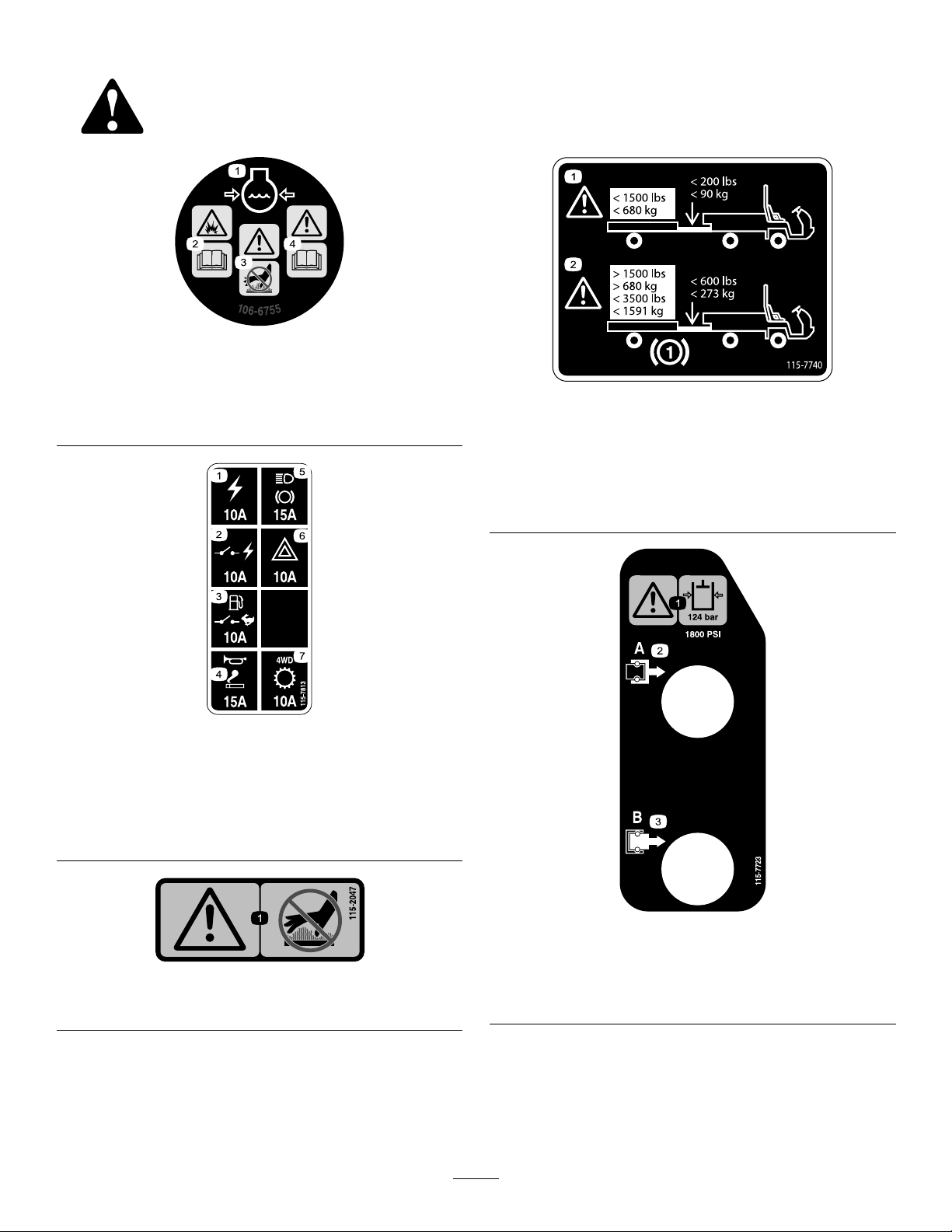
106-6755
1.Enginecoolantunder
pressure.
2.Explosionhazard—read
theOperator'sManual.
115-7813
1.Poweroutlet—10A5.Lights,brake—15A
2.Switchedpower—10A
3.Fuelpump,supervisor
switch—10A
4.Horn,powerpoint—15A
3.Warning—donottouchthe
hotsurface.
4.Warning—readthe
Operator'sManual.
6.Hazard—10A
7.4WD,Transmission—10A
115-7740
1.Warning—maximumtrailerweightis680kg(1500lb),
maximumtongueweightis90kg(200lb).
2.Warning—trailerbrakesarerequiredwhentowinggreater
than680kg(1500lb),maximumtrailerweightwithtrailer
brakesis1591kg(3500lb),maximumtongueweightwith
trailerbrakesis273kg(600lb).
1.Warning—donottouchthehotsurface.
115-7723
1.Warning—thehydraulicoilpressureis124bar(1800psi).
115-2047
2.CouplerA
3.CouplerB
7
Page 8
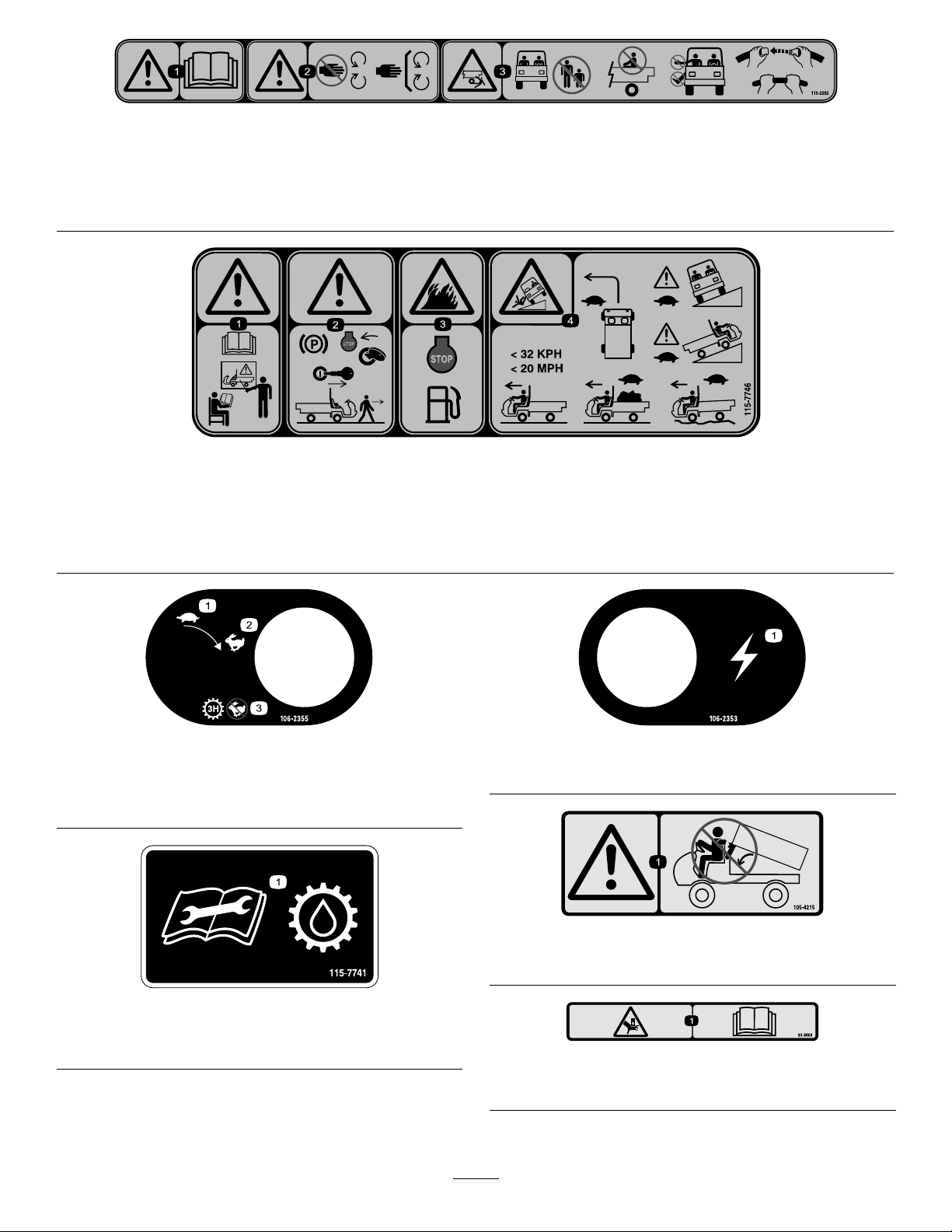
115-2282
1.Warning—readtheOperator'sManual.
2.Warning—stayawayfrommovingparts,keepallguardsandshieldsinplace.
3.Crushing/dismembermenthazardofbystanders—keepbystandersasafedistancefromthevehicle,donotcarrypassengersin
thecargobed,keeparmsandlegsinsideofthevehicleatalltimes,anduseseatbeltsandhandholds.
115-7746
1.Warning—donotoperatethismachineunlessyouaretrained.
2.Warning—locktheparkingbrake,stoptheengine,and
removethestarterkeybeforeleavingthemachine.
106-2355
1.Slow
2.Fast
3.Transmission—thirdhigh;
nofastspeed
3.Firehazard—stoptheenginebeforefueling.
4.Tippinghazard—slowdownandturngradually,usecaution
anddriveslowlywhendrivingonslopes,donotexceed32
kph(20mph),anddriveslowlyoverroughterrainorwhen
carryingafullorheavyload.
106-2353
1.Electricalpowerpoint
115-7741
1.ReadtheOperator’sManualbeforeservicingtransmission
uid.
105-4215
1.Warning—avoidpinchpoints.
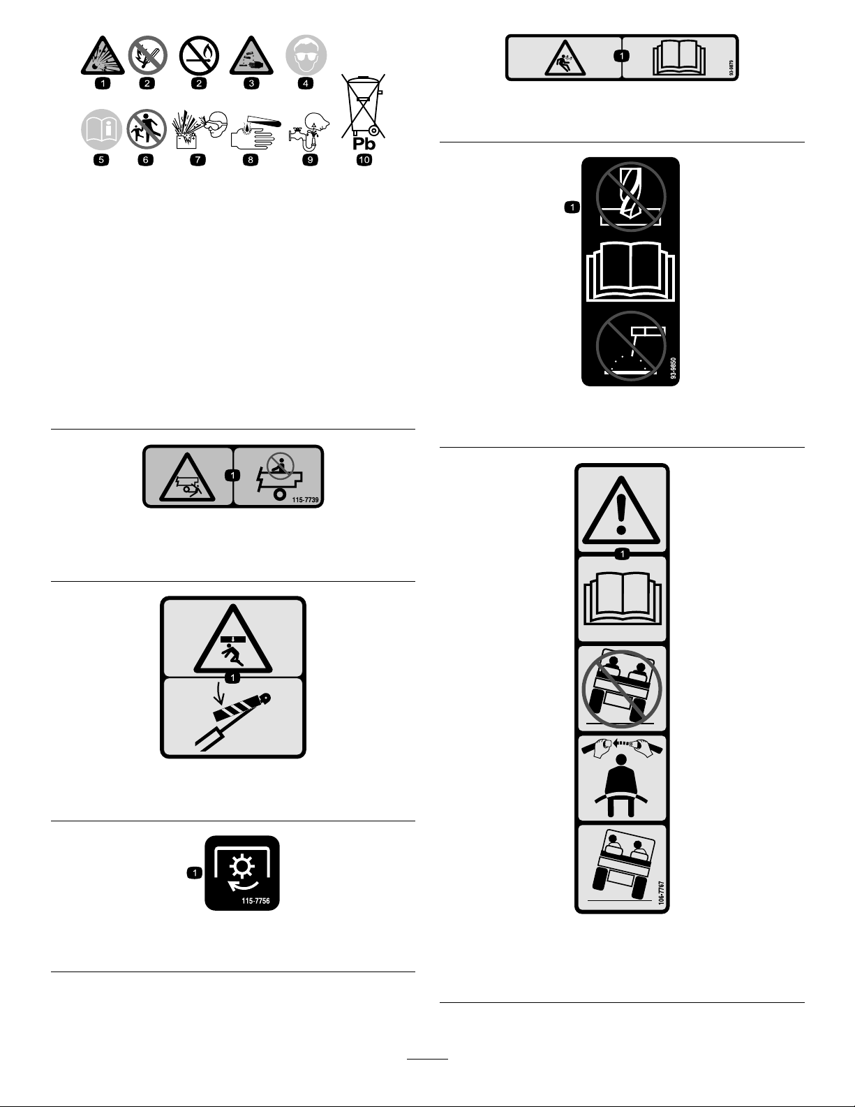
93–9868
1.Crushinghazardofhand—readtheOperator’sManual.
8
Page 9
BatterySymbols
93-9899
Someorallofthesesymbolsareonyourbattery
93-9879
1.Storedenergyhazard—readtheOperator'sManual.
1.Explosionhazard
2.Nore,opename,or
smoking.
3.Causticliquid/chemical
burnhazard
4.Weareyeprotection9.Flusheyesimmediately
5.ReadtheOperator's
Manual.
6.Keepbystandersasafe
distancefromthebattery.
7.Weareyeprotection;
explosivegasescan
causeblindnessandother
injuries
8.Batteryacidcancause
blindnessorsevereburns.
withwaterandgetmedical
helpfast.
10.Containslead;donot
discard.
115-7739
1.Falling,crushinghazard,bystanders—noriderson
machine.
93-9850
1.Donotrepairorrevise—readtheOperator'sManual.
93-9899
1.Crushinghazard—installthecylinderlock.
115-7756
1.Highowhydraulics—engaged
106-7767
1.Warning—readtheOperator'sManual;avoidtippingthe
machine;weartheseatbelt;leanawayfromthedirection
themachineistipping.
9
Page 10
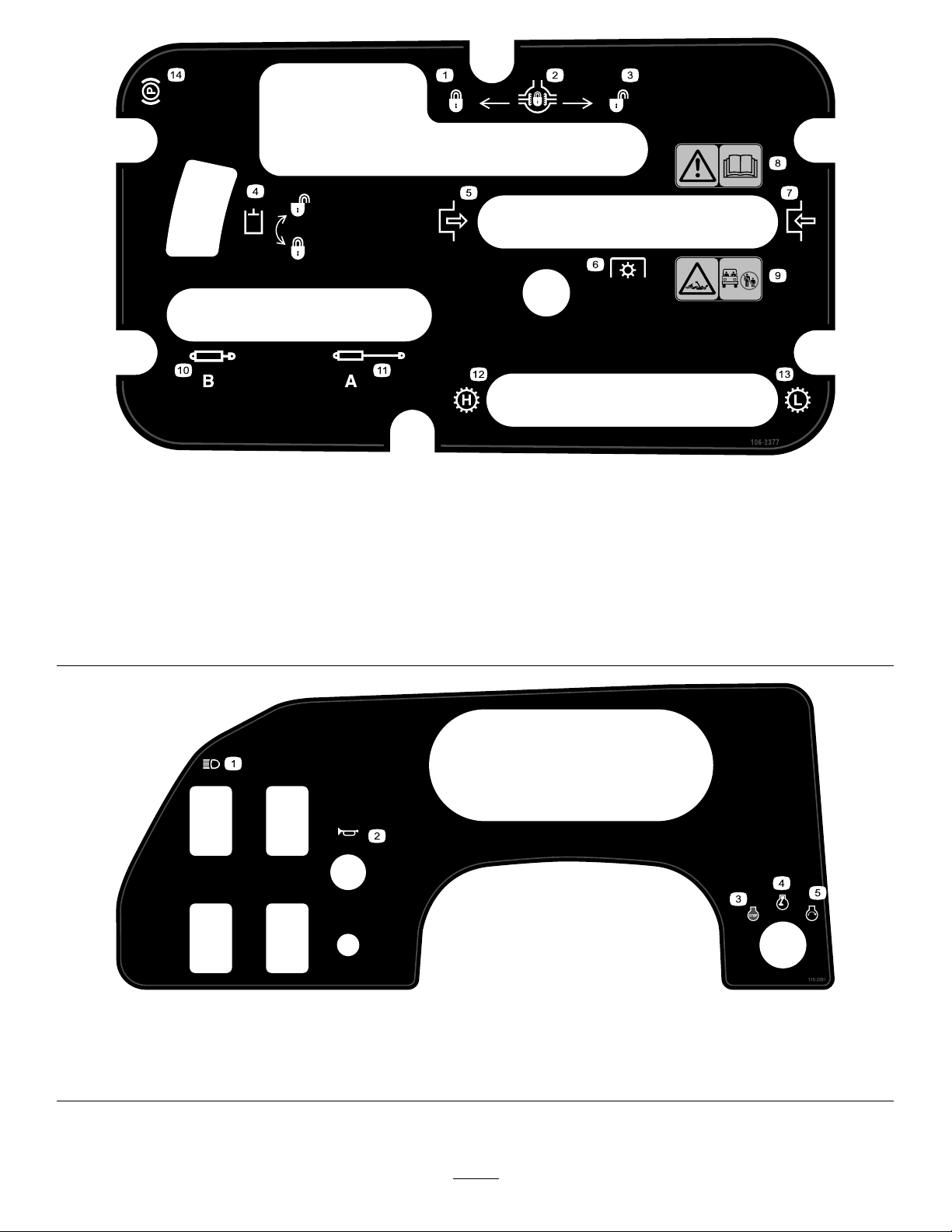
106-2377
1.Locked
2.Differentiallock9.Entanglementhazard,shaft—keepbystander'sasafe
3.Unlocked10.Retracthydraulics
4.Hydrauliclock11.Extendhydraulics
5.Engage12.Transmission—highspeed
6.Powertake-off(PTO)
7.Disengage14.Parkingbrake
8.Warning—readtheOperator'sManual.
distancefromthevehicle.
13.Transmission—lowspeed
1.Headlights4.Engine—run
2.Horn5.Engine—start
3.Engine—stop
115-2281
10
Page 11
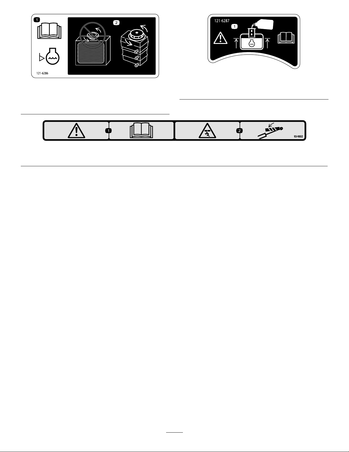
121-6287
1.ReadtheOperator's
Manualbeforechecking
theenginecoolantlevel.
121-6286
2.Donotaddenginecoolant
totheradiator;addengine
coolanttothereservoir,
1.Fillthereservoirwithenginecoolanttothebottomofthe
standpipe.
93-9852
1.Warning—readtheOperator’sManual.2.Crushinghazard—installthecylinderlock.
11
Page 12
Setup
LooseParts
Usethechartbelowtoverifythatallpartshavebeenshipped.
ProcedureDescription
1
2
3
Note:Determinetheleftandrightsideofthemachinefrom
thenormaloperatingposition.
Steeringwheel
ROPSframe
Bolt(1/2inch)
Nopartsrequired
1
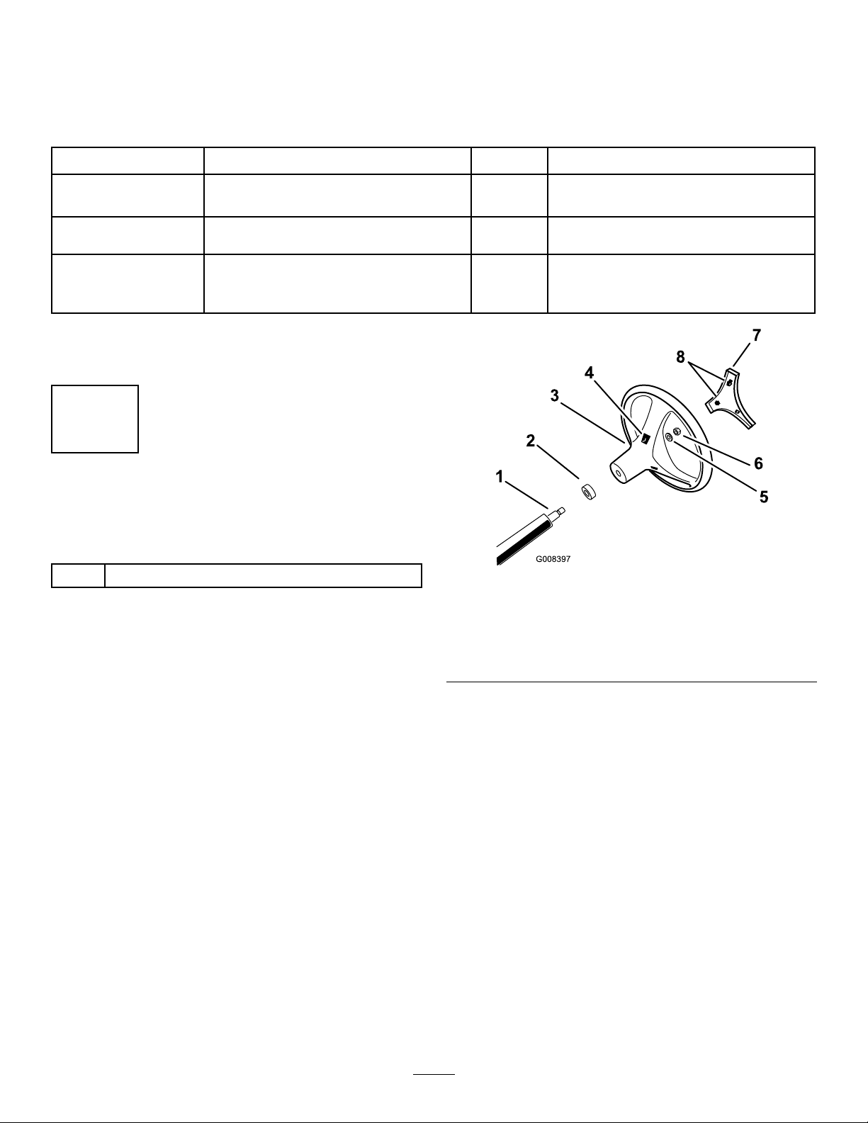
InstallingtheSteeringWheel (TCmodelsonly)
Partsneededforthisprocedure:
Qty.
Use
1
1
6
–
Installthesteeringwheel(TCmodels
only).
MounttheRolloverProtectionSystem
(ROPS).
Checktheengineoil,the
transaxle/hydraulicuid,andthe
brakeuidlevels.
1
Steeringwheel
Procedure
1.Releasethetabsonthebackofthesteeringwheelthat
holdthecentercoverinplace,andremovethecover
fromthehubofthesteeringwheel.
2.Removethelocknutandwasherfromthesteeringshaft.
3.Slidethesteeringwheelandwasherontotheshaft.
Alignthesteeringwheelontheshaftsothatthecross
beamishorizontalwhenthetiresarepointedstraight
aheadandthethickerspokeofthesteeringwheelis
downward.
Note:Thedustcoverispositionontothesteering
shaftatthefactory.
4.Securethesteeringwheeltotheshaftwiththelocknut
(Figure3).Torquethelocknutto24to29N-m(18
to22ft-lb)
Figure3
1.Steeringshaft
2.Dustcover6.Locknut
3.Steeringwheel7.Cover
4.Tabslotsinwheel8.Tabsincover
5.Alignthetabsofthecoverwiththeslotsinthesteering
wheel,andsnapthecoverontothesteering-wheelhub
(Figure3).
5.Washer
12
Page 13
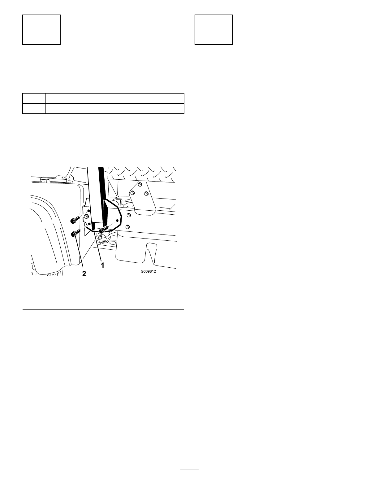
2
3
InstallingtheRollover
ProtectionSystem(ROPS)
Partsneededforthisprocedure:
1
ROPSframe
6
Bolt(1/2inch)
Procedure
1.AligneachsideoftheROPSwiththemountingholes
intheframeateachsideofthevehicleasshownin
Figure4.
CheckingtheFluidLevels
NoPartsRequired
Procedure
1.Checktheengine-oillevelbeforeandaftertheengine
isrststarted;refertoCheckingtheEngine-oilLevel
(page19).
2.Checkthetransaxle/hydraulic-uidlevelbefore
theengineisrststarted;refertoCheckingthe
Transaxle/Hydraulic-uidLevel(page21).
3.Checkthebrake-uidlevelbeforetheengineisrst
started;refertoCheckingtheBrake-uidLevel(page
23).
Figure4
1.ROPS-mountingbracket2.Flangedbolts(1/2x1-1/4
2.SecureeachsideoftheROPStoframewith3anged
bolts(1/2x1-1/4inch),andtightentheboltsto115
N-m(85ft-lb).
inch)
13
Page 14
ProductOverview
Controls
Note:Determinetheleftandrightsidesofthemachine
fromthenormaloperatingposition.
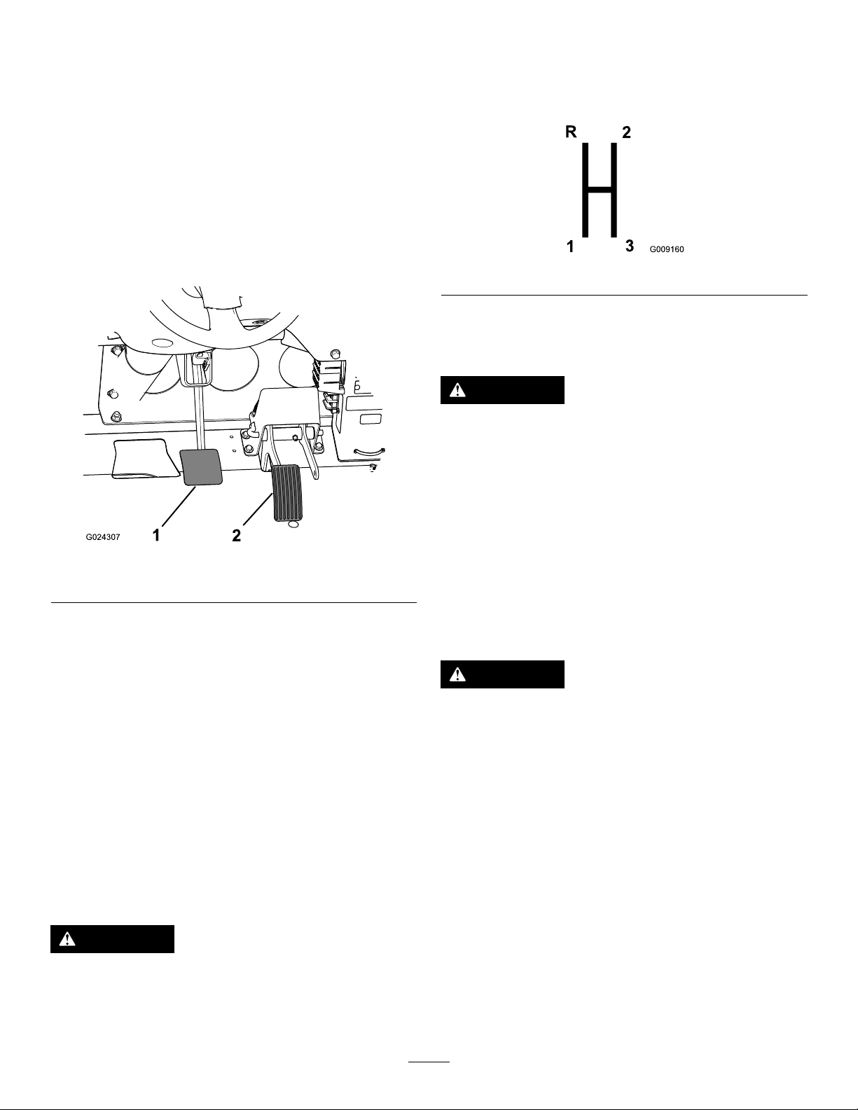
AcceleratorPedal
Theacceleratorpedal(Figure5)givestheoperatortheability
tovarytheengineandgroundspeedofthemachinewhen
thetransmissionisingear.Pressingthepedalincreasesthe
enginerpmandgroundspeed.Releasingthepedaldecreases
theenginerpmandgroundspeedofthemachine.
Gear-shiftLever
Fullypresstheclutchpedalandmovetheshiftlever(Figure
6)intothedesiredgearselection.Adiagramoftheshift
patternisshownbelow.
Figure6
Important:Donotshiftthetransaxletothereverseor
forwardgearunlessthevehicleisstandingstill.Damage
tothetransaxlemayoccur.
CAUTION
Downshiftingfromtoohighaspeedcancausethe
rearwheelstoskidresultinginlossofmachine
controlaswellasclutchand/ortransmission
damage.Shiftsmoothlytoavoidgrindinggears.
Figure5
1.Brakepedal2.Acceleratorpedal
ClutchPedal
Theclutchpedal(Figure5)mustbefullypressedtodisengage
clutchwhenstartingtheengineorshiftingtransmissiongears.
Releasethepedalsmoothlywhenthetransmissionisingear
topreventunnecessarywearonthetransmissionandother
relatedparts.
Important:Donotridetheclutchpedalduring
operation.Theclutchpedalmustbefullyoutorthe
clutchwillslipcausingheatandwear.Neverholdthe
vehiclestoppedonahillusingtheclutchpedal.Damage
totheclutchmayoccur.
BrakePedal
Thebrakepedal(Figure5)isusedtoapplyservicebrakes
tostoporslowvehicle.
DifferentialLock
Thedifferentiallockallowsrearaxletobelockedfor
increasedtraction.Thedifferentiallock(Figure7)maybe
engagedwhenthemachineisinmotion.Movethelever
forwardandtotherighttoengagethelock.
Note:Machinemotionplusaslightturnisrequiredto
engageordisengagedifferentiallock.
CAUTION
Turningwiththedifferentiallockoncanresult
inlossofmachinecontrol.Donotoperatewith
differentiallockonwhenmakingsharpturnsorat
highspeeds;refertoUsingtheDifferentialLock
(page28).
CAUTION
Wornormaladjustedbrakesmayresultinpersonal
injury.Ifthebrakepedaltravelstowithin3.8cm
(1-1/2inches)ofthevehicleoorboard,thebrakes
mustbeadjustedorrepaired.
14
Page 15
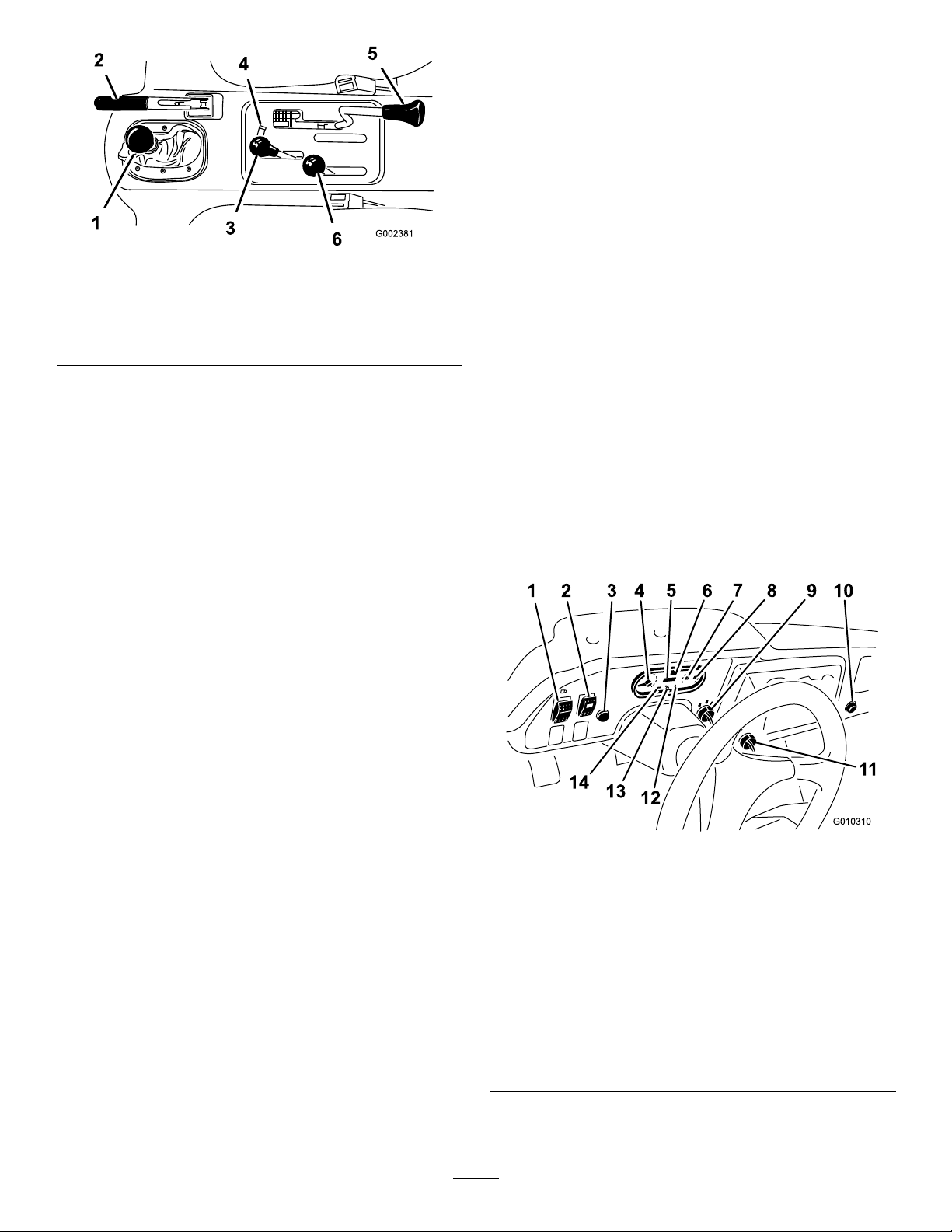
Figure7
1.Gearshiftlever4.Hydraulicliftlock
2.Parkingbrake
3.Hydraulicbedlift6.High–lowrangeshifter
5.Differentiallock
•Presstheclutchpedalfully.
•MovetheleverfullyforwardforHighandfullyrearward
forLow .
Highisforhigherspeeddrivingonlevel,drysurfaceswith
lightloads.
Lowisforlow-speeddriving.Usethisrangewhengreater
thannormalpowerorcontrolisrequired.Forexample,
steepgrades,difcultterrain,heavyloads,slowspeedbut
high-enginespeed(spraying).
Important:ThereisalocationbetweenHighandLow
inwhichthetransaxleisinneitherrange.Donotuse
thispositionasaneutralpositionbecausethevehicle
couldmoveunexpectedlyiftheHigh–Lowshifteris
bumpedandthegear-shiftleverisingear.
StarterSwitch
ParkingBrake
Whenevertheengineisshutoff,settheparkingbrake(Figure
7)inordertopreventthemachinefromaccidentallymoving.
•Tosettheparkingbrake,pullbackonthelever.
•Torelease,pushtheleverforward.
Note:Releasetheparkingbrakebeforemovingthe
machine.
Ifyouparkthemachineonasteepgrade,settheparking
brake,shiftthetransmissionintorstgearonauphillgrade
orreversegearonadownhillgrade,andplacechocksatthe
downhillsideofthewheels.
HydraulicLift
Thehydraulicliftraisesandlowersthebed.Moveitrearward
toraisethebed,andforwardtolowerit(Figure7).
Important:Whenloweringthebed,holdtheleverin
theforwardpositionfor1or2secondsafterthebed
contactstheframetosecureitintheloweredposition.
Donotholdthehydraulicliftineithertheraiseorlower
position,formorethan5seconds,oncethecylinders
havereachedtheendoftheirtravel.
Thestarterswitchislocatedtotherightofthesteering
columnandbelowtheindicatorlightsforthebattery,engine
oilpressure,enginecoolanttemperature,glowplugs(Figure
8).Usethestarterswitchtostartandstoptheengine.The
switchhas3positions:Off,On,andStart.Rotatethekey
clockwisetotheOnpositiontoactivatetheglowplugs.
Whentheglowplugindicatorlightturnsoff,rotatethekey
counterclockwisetotheStartpositiontostarttheengine.
Toshutofftheengine,rotatethekeycounterclockwiseto
theOffposition.
Figure8
Hydraulic-liftLock
Thehydraulic-liftlocklockstheliftlever,sothehydraulic
cylindersdonotoperatewhenthemachineisnotequipped
withabed(Figure7).ItalsolockstheliftleverintheOn
positionwhenusingthehydraulicsforattachments.
High–LowRangeShifter
Thehigh–lowrangeshifteradds3additionalspeedsfor
precisespeedcontrol(Figure7):
•Themachinemustbecompletelystoppedbeforeshifting
betweentheHighandLowrange.
•Shiftonlyonlevelground.
1.Lightswitch8.Fuelgauge
2.High-ow-hydraulics
switch
(TCmodelsonly)
3.Horn
(TCmodelsonly)
4.Tachometer11.3rdhighlockoutswitch
5.Hourmeter
6.Speedometer13.Glow-plugindicator
7.Coolant-temperature
gaugeandlight
9.Ignitionswitch
10.Powerpoint
12.Oilpressurewarninglight
14.Chargeindicator
Note:Removethekeyfromthestarterwhenleavingthe
machine.
15
Page 16
HourMeter
Indicatesthetotalhoursofmachineoperation.Thehour
meter(Figure8)startstofunctionwheneverthekeyswitchis
rotatedtotheOnpositionoriftheengineisrunning.
3rdHighLockoutSwitch
engine,andcheckforpossiblecauses,suchasthealternator
belt(Figure8).
Important:Ifthealternatorbeltislooseorbroken,do
notoperatethemachineuntiladjustmentorrepairis
complete.Failuretoobservethisprecautionmayresult
indamagetotheengine.
Movethe3rd-high-lockoutswitch(Figure8)totheslow
positionandremovethekeytopreventtheuseofthirdgear
whenintheHighrange.Theenginewillshutoffiftheshift
leverismovedtothirdgearwheninHighrange.Thekeyis
removableineitherposition.
LightSwitch
Pushthelightswitch(Figure8)totoggletheheadlightson
oroff.
OilPressureWarningLight
Theoilpressurewarninglightglows(Figure8)ifthe
engine-oilpressuredropsbelowasafelevelwhiletheengine
isrunning.Ifthelightickersorremainson,stopthevehicle,
turnofftheengine,andchecktheoillevel.Iftheoillevelis
low,butaddingoildoesnotcausethelighttogooutwhen
theengineisrestarted,turntheengineoffimmediatelyand
contactyourlocalTorodistributorforassistance.
Checktheoperationofwarninglightsasfollows:
1.Applytheparkingbrake.
2.TurnthestarterkeytotheOn/Preheatposition,but
donotstarttheengine.
Note:Theoilpressurelightshouldglowred.Ifthe
lightdoesnotfunction,eitherabulbisburnedoutor
thereisamalfunctioninthesystemwhichmustbe
repaired.
Note:Ifenginewasjustturnedoff,itmaytake1to
2minutesforthelighttocomeon.
Checktheoperationofwarninglightsasfollows:
•Applytheparkingbrake.
•TurnthestarterkeytotheOn/Preheatposition,butdo
notstarttheengine.Thecoolanttemperature,charge
indicator,andoil-pressurelightsshouldglow.Ifanylight
doesnotfunction,eitherabulbisburnedoutorthereisa
malfunctioninthesystemwhichmustberepaired.
FuelGauge
Thefuelgaugeshowstheamountoffuelinthetank.It
operatesonlywhenstarterswitchisintheOn/Preheat
position(Figure8).Redindicateslowfuellevelandblinking
redindicatesnearempty.
High-owHydraulicsSwitch(TC
modelsonly)
Turnontheswitchtoactivatethehigh-owhydraulics
(Figure8).
HornButton(TCmodelsonly)
Pressingthehornbuttonactivatesthehorn(Figure8).
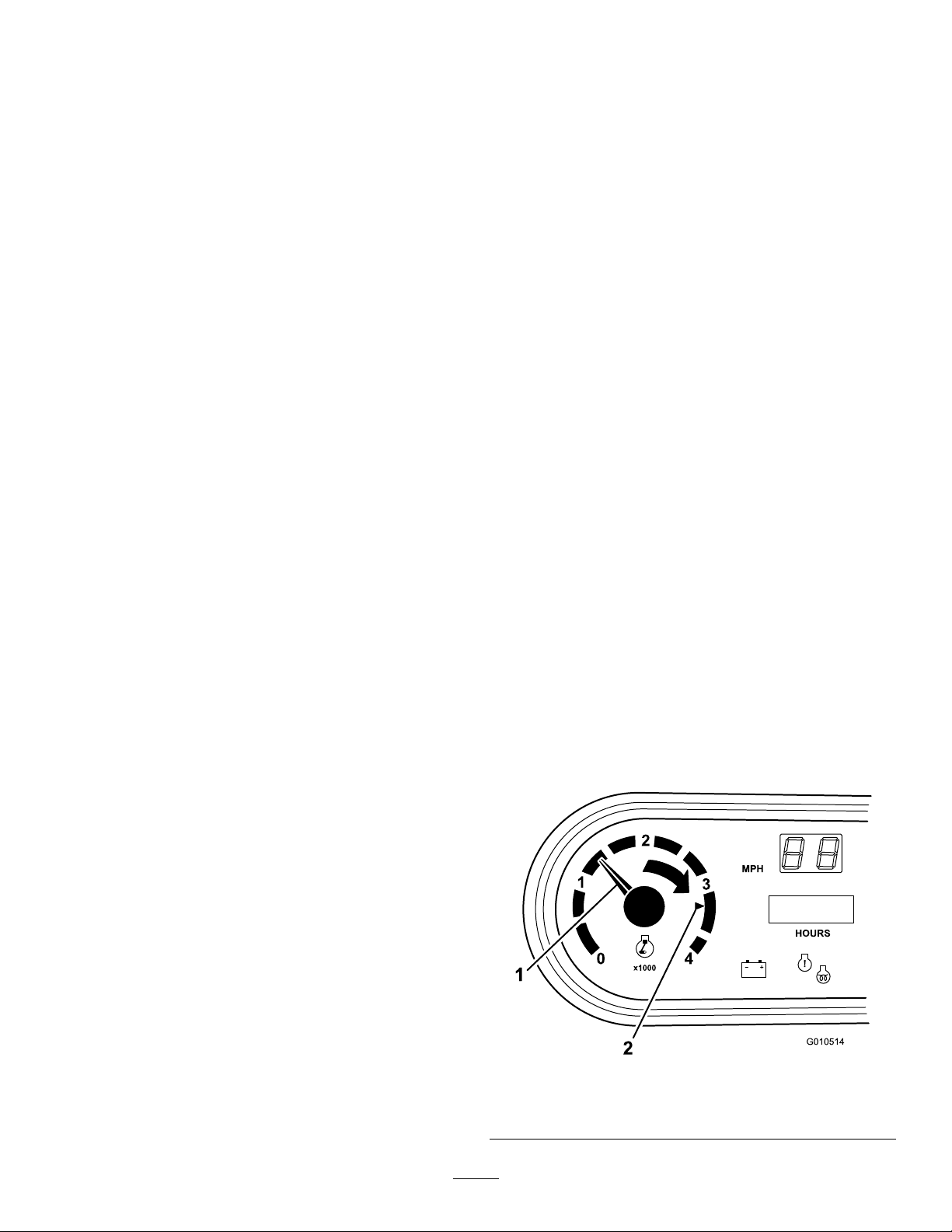
Tachometer
Thetachometerregistersthespeedoftheengine(Figure8
andFigure9).Whitetriangleindicatesthedesiredrpmfor
PTOoperation(Figure9).
Glow-plugIndicator
Theglow-plugindicator(Figure8)willglowredwhenthe
glowplugsareactivated.
Important:Theglowplugindicatorwillturnon,foran
additional15seconds,whentheswitchreturnstothe
Startposition.
Coolant-temperatureGaugeandLight
Registersthecoolanttemperatureoftheengine.Operates
onlywhenthestarterswitchisinOnposition(Figure8).
Theindicatorlightwillilluminateblinkingrediftheengine
overheats.
ChargeIndicator
Illuminateswhenbatteryisbeingdischarged.Ifthelight
illuminatesduringoperation,stopthemachine,turnoffthe
Figure9
1.Speedoftheengine2.3,300rpmfor540rpm
PTOoperation
16
Page 17

Speedometer
Registersthegroundspeedofthemachine(Figure8).The
speedometerisinmphbutcaneasilyconvertedtokm/h;
refertoConvertingtheSpeedometer(page51).
Specications
Note:Specicationsanddesignaresubjecttochange
withoutnotice.
Dimensions
PowerPoint
Usethepowerpoint(Figure8)topoweroptional12volt
electricalaccessories.
PassengerHandHold
Thepassengerhandholdislocatedonthedashboard(Figure
10).
Figure10
OverallWidth160cm(63inches)
Withoutbed:326cm(128inches)
OverallLength
BaseWeight(Dry)
RatedCapacity
(includes91kg(200
lb)operator,91kg
(200lb)passengerand
loadedattachment).
Maximum.Gross
VehicleWeight
TowCapacityTongueweight:272kg(600lb)
GroundClearance18cm(7inches)withnoload
WheelBase
WheelTread(center
linetocenterline)
Height
Withfullbed:331cm(130inches)
With2/3bedinrear-mounting
location:346cm(136inches)
Model07385—887kg(1956lb)
Model07385H—887kg(1956lb)
Model07385TC—924kg(2037lb)
Model07387—914kg(2015lb)
Model07387H—914kg(2015lb)
Model07387TC—951kg(2096lb)
Model07385—1471kg(3244lb)
Model07385TC—1435kg(3163lb)
Model07387—1445kg(3185lb)
Model07387TC—1408kg(3104lb)
2359kg(5200lb)
Maximumtrailerweight:1587kg
(3500lb)
118cm(70inches)
Front:117cm(46inches)
Rear:121cm(48inches)
191cm(75inches)totopofROPS
1.Passengerhandhold
2.Storagecompartment
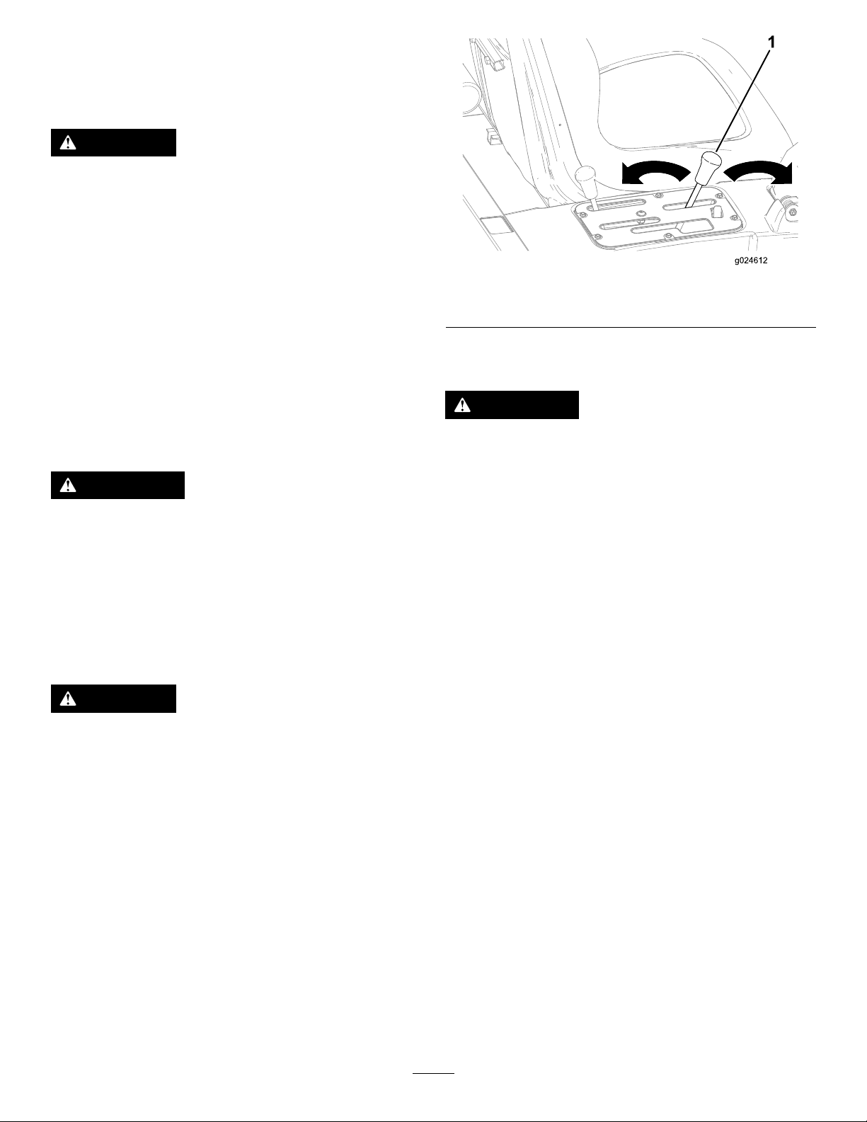
Seat-adjustingLever
Theseatscanbeadjustedbeforeandafterforoperator
comfort(Figure11).
Figure11
1.Seat-adjustinglever
Attachments/Accessories
AselectionofToroapprovedattachmentsandaccessoriesis
availableforusewiththemachinetoenhanceandexpand
itscapabilities.ContactyourAuthorizedServiceDealeror
Distributororgotowww .Toro.comforalistofallapproved
attachmentsandaccessories.
17
Page 18
Operation
Note:Determinetheleftandrightsidesofthemachine
fromthenormaloperatingposition.
CAUTION
Beforeservicingormakingadjustmentstothe
machine,stoptheengine,settheparkingbrake,
andremovethekeyfromtheswitch.Removeany
loadmaterialfromthebedorotherattachment
beforeworkingunderaraisedbed.Neverwork
underaraisedbedwithoutpositioningthesafety
supportonafullyextendedcylinderrod.
OperatingtheCargoBox
Figure12
1.Cargoboxlever
Note:Centerloadsinthecargoboxifpossible.
Note:Removeallcargofromtheboxbeforeliftingthebox
uptoservicethemachine.
RaisingtheCargoBox
WARNING
Drivingthemachinewiththecargoboxraisedmay
causethemachinetotiporrolleasier.Thebox
structuremaybecomedamagedifyouoperatethe
machinewiththeboxraised.
•Onlyoperatethemachinewhenthecargobox
isdown.
•Afteremptyingthecargobox,lowerit.
CAUTION
Ifaloadisconcentratednearthebackofthecargo
boxwhenyoureleasethelatches,theboxmay
unexpectedlytipopeninjuringyouorbystanders.
LoweringtheBox
WARNING
Theweightoftheboxmaybeheavy.Handsor
otherbodypartscouldbecrushed.
Keephandsandotherbodypartsclearwhen
loweringthebox.
Movetheleverforwardtolowerthecargobox(Figure12).
OpeningtheTailgate
1.Ensurethatthecargoboxisloweredcompletely.
2.Openthelatchesontheleftandrightsideofthecargo
boxandlowerthetailgate(Figure13).
•Centerloadsinthecargoboxifpossible.
•Holdthecargoboxdownandensurethatno
oneisleaningovertheboxorstandingbehindit
whenreleasingthelatches.
•Removeallcargofromtheboxbeforeliftingthe
boxuptoservicethemachine.
Movetheleverbackwardtoraisethecargobox(Figure12).
18
Page 19

Figure13
1.Latchhandle3.Latchpin
2.Latchgate
enginehasalreadyran,allowtheoiltodrainbackdowntothe
sumpforatleast10minutesbeforechecking.Iftheoillevel
isatorbelowtheAddmarkonthedipstick,addoiltobring
theoilleveltotheFullmark.Donotoverlltheengine
withoil.IftheoillevelisbetweentheFullandAddmarks,
noadditionaloilisrequired.
1.Positionthemachineonalevelsurface.
2.Removethedipstickandwipeitwithacleanrag
(Figure15).
CheckingtheEngine-oilLevel
ServiceInterval:Beforeeachuseordaily
Engineoiltype:DetergentdieselengineoilAPICH-4or
higher
Engine-oilviscosity:Chooseanengine-oilviscosity
accordingtotheambient-airtemperaturetothetablein
Figure14.
Figure15
1.Dipstick
2.Oil-llcap
3.Insertthedipstickintothetubeandmakesurethatit
isseatedfully(Figure15).
4.Removedipstickandchecktheleveloftheoil(Figure
15).
5.Iftheoillevelislow,removetheoil-llcap(Figure15),
andaddenoughoiltoraisetheleveltotheFullmark
onthedipstick.
6.Installthedipstickrmlyinplace(Figure15).
Figure14
Note:Thebesttimetochecktheengineoiliswhenthe
engineiscoolbeforeithasbeenstartedfortheday.Ifthe
19
Page 20

AddingFuel
UsingBiodieselFuel
Fueltankcapacity:22L(5.85USgallons).
Useonlyclean,freshdieselfuelorbiodieselfuelswithlow
(<500ppm)orultralow(<15ppm)sulfurcontent.The
minimumcetaneratingshouldbe40.Purchasefuelin
quantitiesthatcanbeusedwithin180daystoensurefuel
freshness.
•Usesummergradedieselfuel(No.2-D)attemperatures
above-7°C(20°F)andwintergrade(No.1-DorNo.
1-D/2-Dblend)belowthattemperature.
•Useofwintergradefuelatlowertemperaturesprovides
lowerashpointandcoldowcharacteristicswhichwill
easestartingandreducefuellterplugging.
Note:Useofsummergradefuelabove-7°C(20°F)will
contributetowardlongerfuelpumplifeandincreasedpower
comparedtowintergradefuel.
Important:Donotusekeroseneorgasolineinsteadof
dieselfuel.Failuretoobservethiscautionwilldamage
theengine.
WARNING
Fuelisharmfulorfatalifswallowed.Long-term
exposuretovaporscancauseseriousinjuryand
illness.
•Avoidprolongedbreathingofvapors.
•Keepyourfaceawayfromthenozzleandgas
tankorconditioneropening.
•Keepfuelawayfromyoureyesandskin.
Thismachinecanalsouseabiodieselblendedfuelofup
toB20(20%biodiesel,80%petrodiesel).Thepetrodiesel
portionshouldbeloworultralowsulfur.Observethe
followingprecautions:
•Thebiodieselportionofthefuelmustmeetspecication
ASTMD6751orEN14214.
•TheblendedfuelcompositionshouldmeetASTMD975
orEN590.
•Paintedsurfacesmaybedamagedbybiodieselblends.
•UseB5(biodieselcontentof5%)orlesserblendsincold
weather.
•Monitorseals,hoses,gasketsincontactwithfuelasthey
maybedegradedovertime.
•Fuellterpluggingmaybeexpectedforatimeafter
convertingtobiodieselblends.
•Contactyourdistributorifyouwishformoreinformation
onbiodiesel.
1.Cleantheareaaroundthefuel-tankcap.
2.Removethefuel-tankcap(Figure16).
DANGER
Undercertainconditions,dieselfuelandfuel
vaporsarehighlyammableandexplosive.Are
orexplosionfromfuelcanburnyouandothersand
cancausepropertydamage.
•Beforeremovingthefueltankcap,makesure
thevehicleispositionedonalevelsurface.Open
fueltankcapslowly .
•Useafunnelandllthefueltankoutdoors,in
anopenarea,whentheengineisoffandiscold.
Wipeupanyfuelthatspills.
•Donotllthefueltankcompletelyfull.Addfuel
tothefueltankuntilthelevelis25mm(1inch)
belowthebottomofthellerneck.Thisempty
spaceinthetankallowsthefueltoexpand.
•Neversmokewhenhandlingfuel,andstayaway
fromanopenameorwherefuelfumesmaybe
ignitedbyaspark.
•Storefuelinaclean,safety-approvedcontainer
andkeepthecapinplace.
Figure16
1.Fuel-tankcap
3.Fillthetankslightlybelowthetopofthetank,(bottom
ofthellerneck),theninstallthecap.
Note:Donotoverllthefueltankwithfuel.
4.Wipeupanyfuelthatmayhavespilledtopreventa
rehazard.
20
Page 21

CheckingtheCoolantLevel
ServiceInterval:Beforeeachuseordaily
3.Ifcoolantislow ,removethereservetankcapandadda
50/50mixtureofwaterandpermanentethylene-glycol
antifreeze.
Coolingsystemcapacity:3.7L(4USqt)
Coolanttype:a50/50solutionofwaterandpermanent
ethylene-glycolantifreeze.
CAUTION
Iftheenginehasbeenrunning,thepressurized,hot
coolantcanescapeandcauseburns.
•Donotopentheradiatorcap.
•Allowtheenginetocoolatleast15minutesor
untiltheradiatorcapiscoolenoughtotouch
withoutburningyourhand.
•Usearagwhenopeningthereservetankcap,
andopenthecapslowlytoallowsteamto
escape.
•Donotcheckthecoolantlevelattheradiator;
onlycheckthecoolantlevelatthereservetank.
1.Parkthemachineonalevelsurface.
2.Checkthecoolantlevelinsidethereservetank(Figure
17).
Note:Donotoverllthereservetankwithcoolant.
4.Installthereserve-tankcap.
Checkingthe
Transaxle/Hydraulic-uid
Level
ServiceInterval:Beforeeachuseordaily(checktheuid
levelbeforetheengineisrststartedand
every8hoursordaily ,thereafter.)
Transaxleuidtype:DexronIIIATF
1.Positionthemachineonalevelsurface.
2.Cleantheareaaroundthedipstick(Figure18).
Note:Thecoolantshouldbeuptothebottomofthe
llerneckwhentheengineiscold.
Figure18
1.Dipstick
3.Unscrewthedipstickfromthetopofthetransaxleand
wipeitwithacleanrag.
4.Screwthedipstickintothetransaxleandensurethat
itisfullyseated.
5.Unscrewthedipstickandchecktheuidlevel.
Note:Theuidshouldbeuptotopoftheatportion
ofthedipstick.
6.Ifthelevelislow ,addenoughofthespecieduidto
achievetheproperlevel.
1.Reservetank-cap
2.Reservetank
Figure17
21
Page 22

CheckingtheHighFlow
Hydraulic-uidLevel(TC
modelsonly)
4.Insertthedipstickintothellerneck,thenremoveit
andchecktheuidlevel.
Note:Theuidlevelshouldbebetweenthe2marks
onthedipstick.
ServiceInterval:Beforeeachuseordaily(checkthelevelof
hydraulicuidbeforetheengineisrst
started,anddailythereafter)
Hydraulic-uidtype:T oroPremiumAllSeason
HydraulicFluid(Availablein5gallonpailsor55gallon
drums.SeepartscatalogorTorodistributorforpart
numbers.)
Alternateuids:IftheTorouidisnotavailable,another
conventionalpetroleum–baseduidmaybeusedprovided
itmeetsthefollowingmaterialpropertiesandindustry
specications.Consultwithyourlubricantdistributorto
identifyasatisfactoryproduct.
Note:Torowillnotassumeresponsibilityfordamage
causedbyimpropersubstitutions,souseonlyproducts
fromreputablemanufacturerswhowillstandbehindtheir
recommendation.
HighViscosityIndex/LowPourPointAntiwear
HydraulicFluid,ISOVG46
MaterialProperties:
•Viscosity—ASTMD445cSt@40ºC:44to48/cSt@
100ºC:7.9to8.5
•ViscosityIndex,ASTMD2270—140to152
•PourPoint,ASTMD97—-35ºFto-46ºF
•FZG,Failstage—11orbetter
•Watercontent(newuid)—500ppm(maximum)
IndustrySpecications:
VickersI-286-S,VickersM-2950-S,DenisonHF-0,Vickers
35VQ25(EatonATS373-C)
1.Cleantheareaaroundthellerneckandthecapofthe
hydraulictank(Figure19).
2.Removethecapfromthellerneck.
5.Ifthelevelislow ,addtheappropriateuidtoraise
theleveltotheuppermark;refertoChangingthe
High-owHydraulicuidandFilter(TCmodelsonly)
(page53).
6.Installthedipstickandcapontothellerneck.
7.Starttheengineandturnontheattachment.
Note:Letthemrunforabout2minutestopurgeair
fromthesystem.
Important:Themachinemustberunningbefore
startingthehigh-owhydraulics.
8.Stoptheengineandattachmentandcheckforleaks.
WARNING
Hydraulicuidescapingunderpressurecan
penetrateskinandcauseinjury.
•Makesureallhydraulicuidhosesand
linesareingoodconditionandallhydraulic
connectionsandttingsaretightbefore
applyingpressuretothehydraulicsystem.
•Keepyourbodyandhandsawayfrom
pinholeleaksornozzlesthatejecthigh
pressurehydraulicuid.
•Usecardboardorpapertondhydraulic
leaks.
•Safelyrelieveallpressureinthehydraulic
systembeforeperforminganyworkonthe
hydraulicsystem.
•Seekimmediatemedicalattentionifuid
isinjectedintoyourskin.
Figure19
1.Cap
3.Removethedipstick(Figure19)fromthellerneck
andwipeitwithacleanrag.
Checkingthe Front-differential-oilLevel (4-wheeldrivemodelsonly)
ServiceInterval:Every100hours/Monthly(whichever
comesrst)
Differential-oiltype:Mobil424hydraulicoil
1.Positionthemachineonalevelsurface.
2.Cleantheareaaroundthell/checkplugonsideof
thedifferential(Figure20).
22
Page 23

Figure20
CheckingtheTirePressure
ServiceInterval:Beforeeachuseordaily
Theairpressureinthefronttiresis220kPa(32psi)andthe
reartiresis124kPa(18psi).
Checkthetirepressurefrequentlytoensureproperination.
Ifthetiresarenotinatedtothecorrectpressure,thetires
willwearprematurely.
Figure21isanexampleoftirewearcausedbyunderination.
1.Fill/checkplug
3.Removethell/checkplugandcheckthelevelofthe
oil.
Note:Theoilshouldbeuptohole.
4.Iftheoilislow,addspeciedoil.
5.Installthell/checkplug.
2.Drainplug
CheckingtheTorqueofthe WheelNuts
ServiceInterval:Aftertherst2hours
Aftertherst10hours
Every200hours
WARNING
Failuretomaintainpropertorqueofthewheelnuts
couldresultinfailureorlossofawheelandmay
resultinpersonalinjury.
Figure21
1.Under-inatedtire
Figure22isanexampleoftirewearcausedbyoverination.
Figure22
1.Over-inatedtire
Torquethefrontandrearwheelnutsto109to122
N-m(80to90ft-lb)after1to4hoursofoperation
andagainafter10hoursofoperation.T orqueevery
200hoursthereafter.
CheckingtheBrake-uidLevel
ServiceInterval:Beforeeachuseordaily—Checkthe
brake-uidlevel.(Checkthelevelbefore
theengineisrststartedandevery8
hoursordaily,thereafter.)
Every1,000hours/Every2years(whichevercomes
rst)—Changethebrakeuid.
Brakeuidtype:DOT3brakeuid
Thebrake-uidreservoirislocatedunderthedash.
1.Parkthemachineonalevelsurface.
2.TheuidlevelshouldbeuptotheFulllineonthe
reservoir(Figure23).
23
Page 24

Figure23
1.Brake-uidreservoir
3.Iftheuidlevelislow,cleantheareaaroundthecap,
removethereservoircap,andllthereservoirtothe
properlevelwiththespeciedbrakeuid.
Note:Donotoverllthereservoirwithbrakeuid.
Note:Youcanremovethehoodaccesstothereservoirfrom
thefrontofthemachine(Figure24).
5.Keepyourfootoffoftheacceleratorpedal.
6.TurnthestarterswitchtotheOnposition.Whenthe
glowplugindicatorlightgoesoff,theengineisready
tostart.
7.RotatethestarterkeyswitchtotheStartposition.
Releasethekeyimmediatelywhentheenginestartsand
allowittoreturntotheRunposition.
Note:Theglowplugindicatorwillturnonforanadditional
15seconds,whentheswitchreturnstotheRunposition.
Note:Donotrunthestartermotormorethan10secondsat
atimeorprematurestarterfailuremayresult.Ifenginefails
tostartafter10seconds,turnthekeytotheOffposition.
Checkthecontrolsandstartingprocedure,wait10additional
seconds,andrepeatthestartingoperation.
DrivingtheVehicle
1.Releasetheparkingbrake.
2.Fullypresstheclutchpedal.
3.Movethegearshiftlevertorstgear.
Figure24
1.Brake-uidreservoir
StartingtheEngine
1.Sitontheoperator’sseatandengagetheparkingbrake.
2.DisengagethePTOandhighowhydraulics(ifso
equipped)andmovethehandthrottlelevertotheOff
position(ifsoequipped).
3.MovetheshiftlevertotheNeutralpositionandpress
theclutchpedal.
4.Ensurethatthehydraulic-liftleverisinthecenter
position.
4.Releasetheclutchpedalsmoothlywhilepressingthe
acceleratorpedal.
5.Whenthemachinegainsenoughspeed,removeyour
footfromtheacceleratorpedal,fullypresstheclutch
pedal,movethegearshiftlevertothenextgearand
releasetheclutchpedalwhilepressingtheaccelerator
pedal.
6.Repeattheprocedureuntilthedesiredspeedisattained.
Important:Alwaysstopthemachinebefore
shiftingtoreverseaforwardgearortoaforward
gearfromreverse.
Note:Avoidlongperiodsofengineidling.
Usethechartbelowtodeterminethegroundspeedof
thevehicleat3600rpm.
Gear
1L82.83:14.72.9
2L54.52:17.24.5
3L31.56:112.5
1H32.31:112.27.6
2H21.27:118.511.5
3H12.31:131.919.8
RL86.94:14.52.8
RH33.91:111.67.1
RangeRatio
Speed
(kmh)
Important:Donotattempttopushortowthe
machinetogetitstarted.Damagetothedrive
traincouldresult.
Speed
(mph)
7.7
24
Page 25

StoppingtheMachine
CheckingtheSafety-interlock
Tostopthemachine,removeyourfootfromtheaccelerator
pedal,presstheclutchpedal,thenpressthebrakepedal.
StoppingtheEngine
Tostoptheengine,rotatethestarterkeytotheOffposition
andengagetheparkingbrake.Removethekeyfromthe
switchtopreventaccidentalstarting.
BreakinginaNewMachine
Toprovideproperperformanceandlongmachinelife,follow
theseguidelinesfortherst100operatinghours.
•Checktheuidandengineoillevelsregularlyandbealert
forindicationsofoverheatinginanycomponentofthe
machine.
•Afterstartingacoldengine,letitwarmupforabout15
secondsbeforeshiftingintogear.
•Avoidracingtheengine.
•Toensureoptimumperformanceofthebrakesystem,
burnish(break–in)thebrakesbeforeuse.Toburnishthe
brakes,bringthevehicleuptofullspeed,applythebrakes
torapidlystopthevehiclewithoutlockingupthetires.
Repeatthis10times,waiting1minutebetweenstopsto
avoidoverheatingthebrakes.Thisismosteffectiveifthe
machineisloadedwith454kg(1000lb).
•Varythemachinespeedduringoperation.Avoidexcessive
idling.Avoidfaststartsandquickstops.
System
ServiceInterval:Beforeeachuseordaily
Thepurposeofthesafety-interlocksystemistopreventthe
enginefromcrankingorstartingunlesstheclutchpedalis
pressed.
CAUTION
Ifthesafety-interlockswitchesaredisconnectedor
damagedthemachinecouldoperateunexpectedly
causingpersonalinjury.
•Donottamperwiththeinterlockswitches.
•Checktheoperationoftheinterlockswitches
dailyandreplaceanydamagedswitchesbefore
operatingthemachine.
Note:RefertoAttachmentOperator’sManualforprocedures
oncheckingtheattachmentinterlocksystem.
VerifyingtheClutchInterlockSwitch
1.Sitontheoperator’sseatandengagetheparkingbrake.
2.MovetheshiftlevertotheNeutralposition.
Note:Theenginewillnotcrankifthehydraulic-lift
leverislockedintheforwardposition.
3.Withoutpressingtheclutchpedal,rotatethekey
clockwisetotheStartposition.
•Abreak–inoilfortheengineisnotrequired.The
originalengineoilisthesametypespeciedforregular
oilchanges.
•RefertotheMaintenancesectionforanyspeciallowhour
checks.
Note:Iftheenginecranksorstarts,thereisa
malfunctionintheinterlocksystemthatmustbe
repairedbeforeoperatingthemachine.
VerifyingtheHydraulic-liftLever
InterlockSwitch
1.Sitontheoperator’sseatandengagetheparkingbrake.
2.MovetheshiftlevertotheNeutralpositionandensure
thatthehydraulic-liftleverisinthecenterposition.
3.Pressclutchpedal.
4.Movethehydraulic-liftleverforwardandrotatethe
startkeyclockwisetothestartposition.
Note:Ifenginecranksorstarts,thereisamalfunction
intheinterlocksystemthatmustberepairedbefore
operatingthemachine.
25
Page 26

EnsuringPassengerSafety
EnsuringProperSpeed
Wheneveryouhaveapassengerridinginthemachine,make
sureheorsheiswearingtheseatbeltandholdingonsecurely .
Driveslowerandturnlesssharplybecauseyourpassenger
doesnotknowwhatyouaregoingtodonextandmaynotbe
preparedforturning,stopping,accelerating,andbumps.
Youandyourpassengershouldremainseatedatalltimes,
keepingarmsandlegsinsidethevehicle.Theoperatorshould
keepbothhandsonsteeringwheel,wheneverpossible,and
thepassengershouldusethehandholdsprovided(Figure
25andFigure26).
Speedisoneofthemostimportantvariablesleadingto
accidents.Drivingtoofastfortheconditionscancauseyou
tolosecontrolandhaveanaccident.Speedcanalsomakea
minoraccidentworse.Drivingheadonintoatreeatslow
speedcancauseinjuryanddamage,but,drivingintoatree
athighspeedcandestroythevehicleandkillyouandyour
passenger.
Neverdrivetoofastfortheconditions.Ifthereisanydoubt
abouthowfasttodrive,slowdown.
Whenusingheavyattachments,morethan454kg(1000lb),
suchassprayers,topdressers,orspreaders,etc.,restrictyour
operatingspeedbymovingthe3rdhighlockoutswitchto
theslowposition.
EnsuringProperTurning
Turningisanotherimportantvariableleadingtoaccidents.
Turningtoosharplyfortheconditionscancausethevehicle
tolosetractionandskid,oreventipover.
Wet,sandy,andslipperysurfacesmaketurningmoredifcult
andrisky .Thefasteryouaregoing,theworsethissituation
becomesso,slowdownbeforeturning.
1.Passenger-handhold
1.Handholdandhiprestraint
Figure25
Figure26
Duringasharpturnathigherspeeds,theinsiderearwheel
mayliftoffoftheground.Thisisnotaawinthedesign,it
happenswithmost4-wheelmachineincludingpassengercars.
Ifthishappens,youareturningtoosharplyforthespeedat
whichyouaretraveling.Slowdown!
2.Storagecompartment
EnsuringProperBraking
Itisgoodpracticetoslowdownbeforeyougetnearan
obstacle.Thisgivesyouextratimetostoporturnaway.
Hittinganobstaclecandamagethemachineanditscontents.
Moreimportant,itcaninjureyouandyourpassenger.Gross
machineweighthasamajorimpactonyourabilitytostop
and/orturn.Heavierloadsandheavierattachmentsmake
avehiclehardertostoporturn.Theheaviertheload,the
longerittakestostop.
Thebrakingcharacteristicsalsochangewithnobedor
attachmentonthemachine.Faststopsmaycausetherear
wheelstolockupbeforethefrontwheelslockup,whichmay
affectthecontrolofthemachine.Itisagoodideatodecrease
machinespeedwithnobedorattachment.
Turfandpavementaremuchslipperierwhentheyarewet.
Itcantake2to4timesaslongtostoponwetsurfacesas
ondrysurfaces.
Neverallowpassengersinthedumpboxoronany
attachments.Thevehicleismeanttohaveonedriverand
onlyonepassenger—nomore.
Ifyoudrivethroughstandingwaterdeepenoughtogetthe
brakeswet,theywillnotworkwelluntiltheyaredry.After
drivingthroughwater,youshouldtestthebrakestomake
suretheyworkproperly.Iftheydonot,driveslowlyinrst
gearwhileputtinglightpressureonthebrakepedal.This
willdrythebrakesout.
26
Page 27

Donotdownshiftforbrakingonicyorslipperysurfaces(wet
grass)orwhilegoingdownahillbecauseenginebraking
maycauseskiddingandlossofcontrol.Shifttoalowergear
beforestartingdownahill.
PreventingTipOvers
Themachineisequippedwitharollbar,hiprestraints,seat
belts,andhandhold.TheRolloverProtectionSystem(ROPS)
usedonthemachinewillreducetheriskofseriousorfatal
injuryintheunlikelyeventofatipover,althoughthesystem
cannotprotecttheoperatorfromallpossibleinjuries.
ReplaceadamagedROPS,donotrepairorrevise.Any
alterationoftheROPSmustbeapprovedbythemanufacturer.
Thebestwaytopreventaccidentsinvolvingutilitymachine
isthroughcontinuoussupervisionandtrainingofoperators
andpayingconstantattentiontotheareainwhichvehicle
isbeingoperated.
Thebestwayforoperatorstopreventseriousinjuryordeath
tothemselvesorothers,istofamiliarizethemselveswiththe
properoperationoftheutilityvehicle,tostayalertandto
avoidactionsorconditionswhichcouldresultinaaccident.
Intheeventofatipover,theriskofseriousinjuryordeath
willbereducediftheoperatorisusingtheROPSsystemand
seatbeltsandisfollowingtheinstructionsprovided.
OperatingonHills
WARNING
Tippingorrollingthemachineonahillcouldcause
seriouspersonalinjury.
•Donotoperatethevehicleonsteepslopes.
•Ifenginestallsoryouloseheadwayonahill,
neverattempttoturnvehiclearound.
•Alwaysbackstraightdownahillinreversegear.
•Neverbackdowninneutralorwiththeclutch
depressed,usingonlythebrakes.
•Neverdriveacrossasteephill,alwaysdrive
straightupordown.
•Avoidturningonahill.
•Don’t“droptheclutch”orslamonthebrakes.
Suddenspeedchangecaninitiateatipover.
andcautiouslyaspossible.Nevermakesharporfastturns
onahill.
Ifyoustallorbegintoloseheadwaywhileclimbingasteep
hill,quicklyapplythebrakes,shifttoneutral,starttheengine
andshifttoreverse.Atidlespeed,theengineandtransaxle
dragwillaidthebrakesincontrollingthevehicleonthehill
andhelpyoubackdownthehillmoresafely.
Reducetheweightoftheloadifitisasteephillorifthe
loadhashighcenterofgravity.Remember,loadscanshift,
securethem.
Note:Themachinehasexcellenthill-climbingability.The
differentiallockwillincreasethisability.Hillclimbingtraction
canalsobeincreasedbyaddingweighttotherearofthe
vehicleinoneofthefollowingways:
•Addingweighttoinsideofbox,makingsureitissecured.
•Mountingwheelweightstorearwheels.
•Addingliquidballast(calciumchloride)toreartires.
•Tractionwillincreasewithnopassengerinfrontseat.
LoadingandDumping
Theweightandpositionofthecargoandpassengercan
changethemachinecenterofgravityandthemachine
handling.Toavoidlossofcontrolresultinginpersonalinjury,
followtheseguidelines:
Donotcarryloadswhichexceedtheloadlimitsdescribed
onthemachineweightlabel.
WARNING
Thebedwilllowerwheneverthedumpleveris
pusheddown,evenwhentheengineisoff.Turning
not
offtheenginewill
lowering.Alwaysplacethesafetysupportonthe
extendedliftcylindertoholdtheboxupifyouare
notgoingtoloweritrightaway.
Themachinehasseveralcombinationsofboxes,platforms,
andattachmentsavailable.Thesecanbeusedinvarious
combinationsthatallowformaximumcapacityandversatility.
Thefullsizedboxis140cm(55inches)wideby165cm(65
inches)longandcanholdupto1360kg(3000lb)ofevenly
distributedcargo.
preventtheboxfrom
Useextracarewhenonhills.Nevergoonhillsthatare
extremelysteep.Stoppingwhilegoingdownahillwilltake
longerthanonlevelground.Turningwhilegoingupordown
ahillismoredangerousthanturningonthelevel.Turnswhile
goingdownhill,especiallywiththebrakeson,and,turning
uphillwhiletraversingahillareparticularlydangerous.Even
ataslowspeedandwithoutaload,tipoversaremorelikelyif
youturnonahill.
Slowdownandshiftintoalowergearbeforestartingupor
downahill.Ifyouhavetoturnwhileonahill,doitasslowly
Loadsvaryinhowtheyaredistributed.Sandspreadsout
evenlyandquitelow .Otheritems,suchasbricks,fertilizeror
landscapetimbers,stackhigherinthebox.
Theheightandweightoftheloadhasasignicantinuence
ontipovers.Thehigheraloadisstacked,themorelikelythe
vehicleistotipover.Youmayndthat1360kg(3000lb)
stackstoohighforsafeoperation.Reducingthetotalweight
isonewaytoreducetheriskofatipover.Distributingthe
loadaslowaspossibleisanotherwaytoreducetheriskof
atipover.
27
Page 28

Iftheloadispositionedtowardoneofthesides,itwillmake
themachinemuchmorelikelytotipoveronthatside.This
isespeciallytruewhenturningiftheloadisontheoutside
oftheturn.
WARNING
Tippingorrollingthemachineonahillwillcause
seriousinjury.
Neverpositionheavyloadsbehindtherearaxle.Iftheloadis
positionedsofartotherearthatitisbehindtherearaxle,it
willreducetheweightonthefrontwheelsandthiswillreduce
steeringtraction.Withtheloadallthewaytotheback,the
frontwheelscanevencomeoffofthegroundwhengoing
overbumpsorupahill.Thiswillresultinalossofsteering
andmayleadtothevehicletippingover.
Asageneralrule,positiontheweightoftheloadevenly
fromfronttorearandevenlyfromsidetoside.
Ifaloadisnotsecured,oryouaretransportingaliquidina
largecontainersuchasasprayer,itcanshift.Thisshifting
happensmostoftenwhileturning,goingupordownhills,
suddenlychangingspeeds,orwhiledrivingoverrough
surfaces.Shiftingloadscanleadtotipovers.Alwayssecure
loadssothattheydonotshift.Neverdumptheloadwhile
thevehicleissidewaysonthehill.
Heavyloadsincreasestoppingdistanceandreduceyour
abilitytoturnquicklywithouttippingover.
Therearcargospaceisintendedforloadcarryingpurposes
only,notforpassengers.
UsingtheDifferentialLock
Thedifferentiallockincreasesthemachinetractionbylocking
therearwheelssoonewheelwillnotspinout.Thiscanhelp
whenyouhaveheavyloadstohaulonwetturforslippery
areas,goinguphills,andonsandysurfaces.Itisimportant
toremember,however,thatthisextratractionisonlyfor
temporarylimiteduse.Itsusedoesnotreplacethesafe
operation,alreadydiscussedconcerningsteephillsandheavy
loads.
Thedifferentiallockcausestherearwheelstospinatthe
samespeed.Whenusingdifferentiallockyourabilitytomake
sharpturnsissomewhatrestrictedandmayscufftheturf.
Usethedifferentiallockonlywhenneeded,atslowerspeeds
andonlyinrstorsecondgear.
•Theextratractionavailablewiththedifferential
lockcanbeenoughtogetyouintodangerous
situationssuchasclimbingslopesthataretoo
steeptoturnaround.Beextracarefulwhen
operatingwiththedifferentiallockon,especially
onsteeperslopes.
•Ifthedifferentiallockisonwhenmakinga
sharpturnatahigherspeedandtheinsiderear
wheelliftsofftheground,theremaybealossof
controlwhichcouldcausevehicletoskid.Use
thedifferentiallockonlyatslowerspeeds.
Using4-wheelDrive(4-wheel drivemodelsonly)
TheAutomaticonDemand4-wheeldrivefeature,onthis
vehicledoesnotrequireoperatoractivation.Thefrontwheel
driveisnotengaged(nopowerdeliveredtofrontwheels)
untiltherearwheelsbegintolosetraction.Thebidirectional
clutchsensestherearwheelsslipping,engagesthefront
wheeldrive,anddeliverspowertothefrontwheels.The4
wheeldrivesystemcontinuestodeliverpowertothefront
wheelsuntiltherearwheelshaveenoughtractiontomove
thevehiclewithoutslipping.Oncethisoccurs,thesystem
stopsdeliveringpowertothefrontwheelsandthehandling
characteristicsbecomesimilartothatofa2-wheeldrive
machine.The4wheeldrivesystemfunctionsinbothfroward
andreverse,however,whenturningtherearwheelswillslip
slightlymorebeforepowerisdeliveredtothefrontwheels.
WARNING
Tippingorrollingthemachineonahillwillcause
seriousinjury.
Theextratractionavailablewiththe4-wheeldrive
featurecanbeenoughtogetyouintodangerous
situationssuchasclimbingslopesthataretoo
steeptoturnaround.Becarefulwhenoperating,
especiallyonsteeperslopes.
TransportingtheMachine
Formovingthemachinelongdistances,useatrailer.Make
surethatthemachineissecuredtothetrailer.RefertoFigure
27andFigure28forthelocationofthetie-downpoints.
Important:Trailersweighingover680kg(1500lb)are
requiredtobeequippedwithtrailerbrakes.
Note:Loadthemachineonthetrailerwiththefrontofthe
machinefacingforward.Ifthatisnotpossible,securethe
machinehoodtotheframewithastrap,orremovethehood
28
Page 29

andtransportandsecureitseparatelyorthehoodmayblow
offduringtransport.
Figure27
1.Eyeholeinframe(eachside)
TowingaTrailerwiththe Machine
Themachineiscapableofpullingtrailersandattachmentsof
greaterweightthanthemachineitself.
Severaltypesoftowhitchesareavailableforthemachine,
dependingonyourapplication.ContactyourAuthorized
ToroDistributorfordetails.
Whenequippedwithatowhitchboltedontotherearaxle
tube,yourmachinecantowtrailersorattachmentswitha
GrossTrailerWeight(GTW)upto1587kg(3500lb).Always
loadatrailerwith60%ofthecargoweightinthefrontof
thetrailer.Thisplacesapproximately10%(272kg(600lb)
max.)oftheGrossTrailerW eight(GTW)onthetowhitchof
themachine.
Trailerbrakesarerequiredwheneveryoutowatrailerover
680kg(1500lb)GTWistowedbehindamachine.
Whenhaulingcargoortowingatrailer(attachment),donot
overloadyourmachineortrailer.Overloadingcancausepoor
performanceordamagetothebrakes,axle,engine,transaxle,
steering,suspension,bodystructure,ortires.
Figure28
1.Axle2.Hitchplate
TowingtheMachine
Incaseofanemergency,thevehiclecanbetowedfora
shortdistance.However,Torodoesnotrecommendthisas
astandardprocedure.
WARNING
Towingatexcessivespeedscouldcausemachine
tolosesteeringcontrol.Nevertowthemachineat
fasterthan8km/h(5mph).
Towingthemachineisa2-personjob.Afxatowlineto
holesinthefrontframemember.MovetheshiftertoNeutral
andreleasetheparkingbrake.Ifthemachinemustbemoved
aconsiderabledistance,transportitonatruckortrailer.
Note:Thepowersteeringwillnotfunction,makingit
difcult(increasedeffort)tosteer.
Important:Toreducepotentialfordrivelinedamage,
uselowrange.
Whentowingfth-wheelattachments,likeafairwayaerator,
alwaysinstallthewheelbar(includedwiththefthwheelkit)
topreventthefrontwheelsfromliftingoffthegroundifthe
towedattachmentsmovementissuddenlyimpaired.
UsingtheHydraulicControl
Thehydrauliccontrolsupplieshydraulicpowerfromthe
machinepumpwhenevertheengineisrunning.Thepower
canbeusedthroughthequickcouplersattherearofthe
machine.
CAUTION
Hydraulicuidescapingunderpressurecanhave
sufcientforcetopenetrateskinanddoserious
damage.Caremustbeusedwhenconnecting
ordisconnectinghydraulicquickcouplers.Stop
theengine,applytheparkingbrake,lowerthe
attachment,andplacetheremotehydraulicvalvein
theoatdetentpositiontorelievehydraulicpressure
beforeconnectingordisconnectingquickcouplers.
Important:Ifmultiplemachinesusethesame
attachment,crosscontaminationofthetransmission
uidmayoccur.Changethetransmissionuidmore
frequently
29
Page 30

UsingtheHydraulic-bedLiftLeverto
ControlHydraulicAttachments
•OffPosition
Thisisthenormalpositionforthecontrolvalvewhenit
isnotbeingused.Inthispositiontheworkportsofthe
controlvalveareblockedandanyloadwillbeheldbythe
checkvalvesinbothdirections.
•Raise(QuickCoupler“ A ”Position)
Thisisthepositionwhichwillliftthebed,rearhitch
attachmentorapplypressuretoquickcouplerA.This
alsoallowshydraulicuidtoreturnfromquickcouplerB
toowbackintothevalveandthenouttothereservoir.
Thisisamomentarypositionandwhentheleveris
releaseditspringreturnstothecenterOffposition.
hydraulicmotor.Thispositionmustonlybeusedon
attachmentswithahydraulicmotorattached.
Important:Ifusedwithahydrauliccylinder
ornoattachment,theOnpositioncausesthe
hydraulic-uidowtogooverareliefvalvewhich
candamagethehydraulicsystem.Usethisposition
onlymomentarilyorwithamotorattached.
Important:Checkhydraulic-uidlevelafter
installationofanattachment.Checktheoperation
oftheattachmentbycyclingtheattachmentseveral
timestopurgeairfromsystem,thenrecheck
hydraulic-uidlevel.Theattachmentcylinderwill
slightlyaffectuidlevelinthetransaxle.Operation
ofvehiclewithlowhydraulic-uidlevelcandamage
thepump,remotehydraulics,powersteering,and
thevehicletransaxle.
ConnectingtheQuickCouplers
Important:Cleandirtfromquickcouplersbefore
connecting.Dirtycouplerscanintroducecontamination
intothehydraulicsystem
Figure29
1.QuickcouplerAposition2.QuickcouplerBposition
•Lower(QuickCouplerBPosition)
Thispositionwilllowerthebed,rearhitchattachment,
orapplypressuretoquickcouplerB.Thisalsoallows
hydraulicuidtoreturnfromquickcouplerAtoow
backintothevalveandthenouttothereservoir.Thisis
amomentarypositionandwhentheleverisreleasedit
springreturnstothecenteroffposition.Momentarily
holdingandthenreleasingthecontrolleverinthis
positionwillprovidehydraulicuidowtoquickcoupler
Bwhichprovidespowerdownontherearhitch.When
released,itwillholdthedownpressureonthehitch.
Important:Ifusedwithahydrauliccylinder,
holdingthecontrolleverinthelowerpositioncauses
thehydraulic-uidowtogooverareliefvalvewhich
candamagethehydraulicsystem.
1.Pullbackthelockingringonthecoupler.
2.Insertthehosenippleintothecoupleruntilitsnaps
intoposition.
Note:Whenattachingremoteequipmenttothequick
couplers,determinewhichsiderequirespressure,thenattach
thathosetoquickcouplerB,whichwillhavepressurewhen
thecontrolleverispushedforwardorlockedintheOn
position.
DisconnectingtheQuickCouplers
Note:Withboththevehicleandattachmentturnedoff,
movetheliftleverbackandforthtoremovethesystem
pressureandeasethedisconnectionofthequickcouplers.
1.Pullbackthelockingringonthecoupler.
2.Pullthehosermlyfromthecoupler.
Important:Cleanandinstallthedustplugand
dustcoverstothequickcouplerendswhennot
inuse.
•OnPosition
ThispositionissimilartoLower(quickcouplerB
position).Italsodirectshydraulicuidtoquickcoupler
Bexceptthattheleverisheldinthispositionbya
detentleverinthecontrolpanel.Thisallowshydraulic
uidtoowcontinuouslytoequipmentthatusesa
30
Page 31

TroubleshootingtheHydraulicControl
•Difcultyinconnectingordisconnectingquickcouplers.
Thepressurenotrelieved(thequickcouplerisunder
pressure).
•Thepowersteeringisturningwithgreatdifcultyorit
isnotturningatall.
–Thehydraulic-uidlevelislow .
–Thehydraulic-uidtemperatureishot.
–Thepumpisnotoperating.
•Therearehydraulicleaks.
–Thettingsareloose.
–Thettingismissingtheo-ring.
•Anattachmentdoesnotfunction.
–Thequickcouplersarenotfullyengaged.
–Thequickcouplersareinterchanged.
•Thereisasquealingnoise.
–RemovethevalveleftintheOndetentposition
causinghydraulicuidtoowoverthereliefvalve.
–Thebeltisloose.
•Theenginewillnotstart.
Thehydraulicleverislockedinforwardposition
31
Page 32

Maintenance
RecommendedMaintenanceSchedule(s)
MaintenanceService
Interval
Aftertherst2hours
Aftertherst8hours
Aftertherst10hours
Aftertherst50hours
Beforeeachuseordaily
MaintenanceProcedure
•T orquethefrontandrearwheelnuts.
•Checktheconditionandtensionofthealternatorbelt.
•T orquethefrontandrearwheelnuts.
•Checktheadjustmentoftheshiftcables.
•Checktheadjustmentoftheparkingbrake.
•Replacethehydrauliclter.
•Changethehigh-owhydraulicuidlter(TCmodelsonly).
•Changetheengineoilandlter.
•Adjusttheenginevalveclearance.
•Checktheengine-oillevel.
•Checkthelevelofthecoolant.
•Checkthetransaxle/hydraulic-uidlevel.(checktheuidlevelbeforetheengine
isrststartedandevery8hoursordaily,thereafter.)
•Checkthehighowhydraulic-uidlevel(TCmodelsonly).(checkthelevelof
hydraulicuidbeforetheengineisrststarted,anddailythereafter)
•Checkthetirepressure.
•Checkthebrake-uidlevel.(Checkthelevelbeforetheengineisrststartedand
every8hoursordaily ,thereafter.)
•Checktheoperationofthesafety-interlocksystem.
•Checktheairlterserviceindicator.
•Drainwaterorothercontaminantsfromthewaterseparator.
•Removedebrisfromtheengineareaandradiator(cleanmorefrequentlyindirty
conditions).
Every25hours
Every50hours
Every100hours
Every200hours
Every400hours
Every600hours
•Removetheaircleanercover,cleanoutdebris,andchecktheairlterservice
indicator.
•Checkthebattery-uidlevel(every30daysifinstorage).
•Checkthebattery-cableconnections.
•Checktheleveloffrontdifferentialoil(4-wheeldrivemodelsonly).
•Greaseallbearingsandbushings(lubricatemorefrequentlyinheavyduty
applications).
•Changetheengineoilandlter.
•Inspecttheconditionofthetires.
•T orquethefrontandrearwheelnuts.
•Inspecttheconstant-velocitybootforcracks,holes,oralooseclamp.
•Checktheadjustmentoftheshiftcables.
•Checktheadjustmentofthehigh-to-lowcable.
•Checktheadjustmentofthedifferential-lockcable.
•Checktheadjustmentoftheparkingbrake.
•Checktheadjustmentofthebrakepedal.
•Checktheconditionandtensionofthealternatorbelt.
•Checktheadjustmentoftheclutchpedal.
•Inspecttheserviceandparkingbrakes.
•Checkthefuellinesandconnections.
•Replacethefuel-ltercanister .
•Checkthefrontwheelalignment.
•Visuallyinspectthebrakesforwornbrakeshoes.
•Changethesafetyairlter(morefrequentlyindustyordirtyconditions).
•Adjusttheenginevalveclearance.
32
Page 33

MaintenanceService
Interval
Every800hours
Every1,000hours
Note:Determinetheleftandrightsidesofthemachinefromthenormaloperatingposition.
MaintenanceProcedure
•Changethefront-differentialoil.
•Changethehydraulicuidandcleanthestrainer.
•Replacethehydrauliclter.
•Changethehigh-owhydraulicuidandlter(TCmodelsonly).
•Changethebrakeuid.
•Drain/ushthefueltank.
•Flushorreplacethecoolant-systemuid.
DANGER
Onlyqualiedandauthorizedpersonnelshallbepermittedtomaintain,repair,adjust,orinspectthe
machine.
Avoidrehazardsandhavereprotectionequipmentpresentintheworkarea.Donotuseanopename
tochecklevelorleakageoffuel,batteryelectrolyte,orcoolant.Donotuseopenpansoffuelorammable
cleaninguidsforcleaningparts.
CAUTION
Ifyouleavethekeyinthestarterswitch,someonecouldaccidentlystarttheengineandseriouslyinjure
youorotherbystanders.
Removethekeyfromthestarterswitchbeforeyoudoanymaintenance.
OperatinginAdverseConditions
Important:Ifthemachineissubjectedtoanyoftheconditionslistedbelow,maintenanceshouldbeperformed
twiceasfrequently:
•Desertoperation
•Coldclimateoperationbelow0°C(32°F)
•Trailertowing
•Frequentoperationondustyroads
•Constructionwork
•Afterextendedoperationinmud,sand,water,orsimilardirtyconditions,haveyourbrakesinspectedandcleanedassoonas
possible.Thiswillpreventanyabrasivematerialfromcausingexcessivewear.
33
Page 34

Premaintenance
Procedures
Manyofthesubjectscoveredinthismaintenancesectionrequireraisingandloweringthebed.Thefollowingprecautionsmust
betakenorseriousinjuryordeathcouldresult.
WARNING
Beforeservicingormakingadjustmentstothemachine,stopengine,setparkingbrake,andremovethe
keyfromthestarterswitch.Removeanyloadmaterialfromthebedorotherattachmentbeforeworking
underaraisedbed.Neverworkunderaraisedbedwithoutpositioningthesafetysupportonafully
extendedcylinderrod.
UsingtheBedSupport
Important:Alwaysinstallorremovethebedsupport
fromtheoutsideofthebed.
1.Raisethebeduntiltheliftcylindersarefullyextended.
2.Removethebedsupportfromthestoragebracketson
backoftheROPSpanel(Figure30).
Figure30
1.Bedsupport
3.Pushthebedsupportontothecylinderrod,making
surethatthesupportendtabsrestontheendof
cylinderbarrel,andonthecylinderrodend(Figure31).
Figure31
1.Bedsupport3.Bed
2.Cylinderbarrel
4.Removethebedsupportfromthecylinderandinsertit
intothebracketsonthebackoftheROPSpanel.
CAUTION
Donottrytolowerbedwithbedsafetysupport
oncylinder.
34
Page 35

RemovingtheFullBed
InstallingtheFullBed
1.Starttheengine,engagethehydraulic-liftlever,and
lowerthebeduntilthecylindersarelooseintheslots.
2.Releasetheliftleverandturnofftheengine.
3.Removethelynchpinsfromtheouterendsofthe
cylinderrodclevispins(Figure32).
Note:Ifthebedsideswillbeinstalledontheatbed,itis
easiertoinstallthembeforeinstallingthebedonthemachine.
Note:Ensurethattherearpivotplatesareboltedtothebed
frame/channelsothatlowerendanglestotherear(Figure33).
Figure33
Figure32
1.Cylinderrodend
2.Bed-mountingplate
3.Clevispin6.Frontslots(2/3bed)
4.Removetheclevispinssecuringthecylinderrodends
tothebed-mountingplatesbypushingthepinstowards
theinside(Figure32).
5.Removethelynchpinsandclevispinssecuringthe
pivotbracketstotheframechannels(Figure32).
6.Liftthebedoffofthemachine.
4.Lynchpin
5.Rearslots(fullbed)
CAUTION
Thefullbedweighsapproximately148kg(325
lb),sodonottrytoinstallorremoveitby
yourself.Useanoverheadhoistorgetthehelp
of2or3otherpeople.
7.Storethecylindersinthestorageclips.
8.Engagethehydrauliclift-lockleveronthemachineto
preventaccidentalextensionoftheliftcylinders.
1.Left,rearcornerofbed4.Clevispin
2.Machineframechannel
3.Pivotplate
5.Lynchpin
CAUTION
Thefullbedweighsapproximately148kg(325lb),
sodonottrytoinstallorremoveitbyyourself.Use
anoverheadhoistorgetthehelpof2or3other
people.
Note:Ensurethatthespacerbracketsandwearblocks
(Figure34)areinstalledwiththecarriageboltheads
positionedinsidethemachine.
35
Page 36

Figure34
1.Wearblock
2.Spacerbracket
1.Ensurethattheliftcylindersarefullyretracted.
2.Carefullysetthebedontothemachineframealigning
therearbedpivot-plateholeswiththeholesintherear
framechannelandinstall2clevispinsandlynchpins
(Figure34).
3.Withthebedlowered,secureeachcylinderrodend,to
theappropriateslotsinthebed-mountingplateswitha
clevispinandlynchpin.
3.Carriagebolt
RaisingtheMachine
DANGER
Amachineonajackmaybeunstableandslipoffof
thejack,injuringanyonebeneathit.
•Donotstartthemachinewhilethemachineis
onajack.
•Alwaysremovethekeyfromtheswitchbefore
gettingoffofthemachine.
•Blockthetireswhenthemachineisonajack.
•Donotstarttheenginewhilethemachineisonajack,
becausetheenginevibrationorwheelmovementcould
causethemachinetoslipoffofthejack.
•Donotworkunderthemachinewithoutjackstands
supportingit.Themachinecouldslipoffajack,injuring
anyonebeneathit.
•Whenjackingupthefrontofthevehicle,alwaysplacea2
x4block(orsimilarmaterial)betweenthejackandthe
machineframe.
•Thejackingpointatthefrontofthemachineisunderthe
frontcenterframesupport(Figure35)andattherearitis
undertheaxle(Figure36).
4.Inserttheclevispinfromoutsideofthebedwiththe
lynchpintowardtheoutside(Figure34).
Note:Therearslotsareforafullbedinstallationand
frontslotsarefora2/3bedinstallation.
Note:Theenginemayneedtobestartedtoextendor
retractthecylindersforalignmentwiththeholes.
Note:Theunusedslotcanbepluggedwithaboltand
nuttopreventassemblyerrors.
5.Starttheengineandengagethehydraulicliftleverto
raisethebed.
6.Releasetheliftleverandturnofftheengine.
7.Installthebedsafetysupporttopreventaccidental
loweringofthebed;refertoUsingtheBedSupport
(page34).
8.Installthelynchpinstotheinsideendsoftheclevis
pins.
Note:Iftheautomatictailgatereleasehasbeen
installedonthebed,ensurethatthefrontdumplink
rodhasbeenplacedontheinsideoftheleftsideclevis
pinbeforethelynchpinisinstalled.
Figure35
1.Frontjackingpoints
36
Page 37

Figure36
1.Rearjackingpoints
RemovingtheHood
1.Whilegraspingthehoodintheheadlightopenings,lift
uponthehoodtoreleasethelowermountingtabs
fromtheframeslots(Figure37).
InstallingtheHood
1.Connectthelights.
2.Insertthetopmountingtabsintotheframeslots.
3.Insertthelowermountingtabsintotheframeslots.
4.Ensurethatthehoodisfullyengagedinthetop,sides
andbottomgrooves.
Figure37
1.Hood
2.Pivotthebottomofthehoodupwarduntilthetop
mountingtabscanbepulledfromtheframeslots
(Figure37).
3.Pivotthetopofthehoodforward,andunplugthewire
connectorsfromtheheadlights(Figure37).
4.Removethehood.
37
Page 38

Lubrication
GreasingtheBearingsand Bushings
ServiceInterval:Every100hours(lubricatemorefrequently
inheavydutyapplications).
Themachinehasgreasettingsthatmustbelubricated
regularlywithNo.2GeneralPurposeLithium-BaseGrease.
Thegreasettinglocationsandquantitiesareasfollows:
•Balljoints(4),tierods(2),pivotmounts(2)andsteering
cylinder(2)(Figure38)
•Springtower(2)(Figure39)
•Clutch(1),accelerator(1),brake(qty .1)(Figure40)
•U-joint(18)and4wheeldriveshaft(3)(Figure41)
Important:Whengreasingthedriveshaftuniversal
shaftbearingcrosses,pumpgreaseuntilitcomesout
ofall4cupsateachcross.
1.Wipeeachgreasettingcleansoforeignmattercannot
beforcedintothebearingorbushing.
Figure39
2.Pumpgreaseintoeachbearingorbushing.
3.Wipeoffexcessgrease.
Figure38
Figure40
38
Page 39

Figure41
39
Page 40

EngineMaintenance
ServicingtheAirCleaner
ServiceInterval:Beforeeachuseordaily—Checktheair
lterserviceindicator.
Every25hours
Every600hours—Changethesafetyairlter(more
frequentlyindustyordirtyconditions).
Inspecttheaircleanerandhosesperiodicallytomaintain
maximumengineprotectionandtoensuremaximumservice
life.Checktheair-cleanerbodyfordamagewhichcould
possiblycauseanairleak.Replaceadamagedair-cleanerbody .
Inspectandchangetheair-cleanerlterasdescribedinthe
followingprocedure:
1.Releasethelatchesontheaircleanerandpullthe
air-cleanercoverofftheair-cleanerbody(Figure42).
Note:Inspecttheelementfortears,anoilylm,or
damagetotherubberseal.Ifthelterisdamageddo
notuseit.
6.Ifyouarereplacingthesafetylter,carefullyslidethe
newlterintothelterbody(Figure42).
Note:Takespecialcaretokeepparticulatesfrom
droppingintothecleanareasoftheairlterhousing.
Note:Topreventenginedamage,alwaysoperatethe
enginewithbothairltersandcoverinstalled.
7.Carefullyslidetheprimarylteroverthesafetylter
(Figure42).
Note:Ensurethatitisfullyseatedbypushingonthe
outerrimofthelterwhileinstallingit.
8.Installtheair-cleanercoverwiththesidefacingup,and
securethelatches(Figure42).
ChangingtheEngineOiland Filter
ServiceInterval:Aftertherst50hours
Figure42
1.Air-cleanercover2.Filter
2.Squeezethedustcapsidestoopenitandknockthe
dustout.
3.Gentlyslidetheprimarylteroutoftheair-cleaner
body(Figure42).
Note:Avoidknockingthelterintothesideofthe
body.
Note:Donotattempttocleantheprimarylter.
4.Removethesafetylteronlyifyouintendtoreplaceit.
Important:Neverattempttocleanthesafetylter.
Ifthesafetylterisdirty,thentheprimarylteris
damagedandbothltersshouldbereplaced.
5.Inspectthenewlter(s)fordamagebylookinginto
thelterwhileshiningabrightlightontheoutsideof
thelter.
Every100hours
Engineoilcapacity:3.2L(3.4USqt)
Engineoiltype:DetergentdieselengineoilAPICH-4or
higher
Engine-oilviscosity:Chooseanengine-oilviscosity
accordingtotheambient-airtemperaturetothetablein
Figure43.
Figure43
1.Raisethebedandplacethesafetysupportonthe
extended-liftcylindertoholdupthebed.
2.Removethedrainplugandletoilowintoadrainpan
(Figure44).
Note:Holesinthelterwillappearasbrightspots.
40
Page 41

Figure44
FuelSystem
Maintenance
CheckingtheFuelLinesand Connections
ServiceInterval:Every400hours/Yearly(whichevercomes
rst)
1.Engineoil-drainplug
3.Whentheoilstops,installthedrainplug.
4.Removetheoillter(Figure45).
Every1,000hours/Every2years(whichevercomes
rst)
Inspectthefuellinesandconnectionsfordeterioration,
damage,orlooseconnections.
ServicingtheFuelFilter/Water Separator
DrainingtheFuelFilter/WaterSeparator
ServiceInterval:Beforeeachuseordaily—Drainwater
orothercontaminantsfromthewater
separator.
1.Placeacleancontainerunderthefuellter(Figure46).
2.Loosenthedrainplugonthebottomofthelter
canister.
Figure45
1.Engine-oillter
5.Applyalightcoatofcleanoiltothenewlterseal
beforescrewingiton.
6.Screwthelteronuntilthegasketcontactsthe
mountingplate,thentightenthelter1/2to2/3of
aturn.
Note:Donotovertighten.
7.Addoiltothecrankcase;refertoCheckingthe
Engine-oilLevel(page19).
Figure46
1.Waterseparatorltercanister
3.Tightenthedrainplugonthebottomofthelter
canister.
41
Page 42

ChangingtheFuel-lterCanister
ServiceInterval:Every400hours—Replacethefuel-lter
canister.
1.Drainthewaterfromthewaterseparator;referto
DrainingtheFuelFilter/WaterSeparator(page41).
2.Cleantheareawherethelter-canistermounts(Figure
46).
3.Removetheltercanisterandcleanthemounting
surface.
4.Lubricatethegasketontheltercanisterwithcleanoil.
5.Installtheltercanisterbyhanduntilthegasket
contactsmountingsurface,thenrotateitanadditional
1/2turn.
6.Tightenthedrainplugonthebottomofthelter
canister.
ElectricalSystem
Maintenance
ServicingtheFuses
Thefusesfortheelectricalsystemarelocatedunderthe
centerofthedashpanel(Figure47andFigure48).
Figure47
1.Fuses
Figure48
1.Poweroutlet—10A5.Lights,brake—15A
2.Switchedpower—10A
3.Fuelpump,supervisor
switch—10A
4.Horn,powerpoint—15A
6.Hazard—10A
7.4WD,Transmission—10A
42
Page 43

JumpStartingtheMachine
WARNING
Jumpstartingcanbedangerous.Toavoidpersonal
injuryordamagetoelectricalcomponentsin
machine,observethefollowingwarnings:
•Neverjumpstartwithavoltagesourcegreater
than15voltsDCThiswilldamagetheelectrical
system.
•Neverattempttojumpstartadischargedbattery
thatisfrozen.Itcouldruptureorexplodeduring
jumpstarting.
•Observeallbatterywarningswhilejumpstarting
yourmachine.
•Besureyourmachineisnottouchingthejump
startmachine.
•Connectingcablestothewrongpostcould
resultinpersonalinjuryand/ordamagetothe
electricalsystem.
1.Squeezethebatterycovertoreleasethetabsfrom
batterybase,andremovethebatterycoverfromthe
batterybase(Figure49).
Connectthejumpercabletotheengineorframe.Do
notconnectthejumpercabletothefuelsystem.
Figure50
1.Battery
4.Starttheengineinthemachineprovidingthejump
start.
Note:Letitrunafewminutes,thenstartyourengine.
5.Removethenegativejumpercablerstfromyour
engine,thenthebatteryintheothermachine.
Figure49
1.Batterycover
2.Connectajumpercablebetweenthepositivepostsof
the2batteries(Figure50).Thepositivepostmaybe
identiedbya+signontopofthebatterycover.
3.Connectoneendoftheotherjumpercabletothe
negativeterminalofthebatteryintheothermachine.
6.Installthebatterycovertothebatterybase.
Note:ThenegativeterminalhasNEGonthebattery
cover.
Note:Donotconnecttheotherendofthejumper
cabletothenegativepostofthedischargedbattery.
43
Page 44

ServicingtheBattery
DriveSystem
ServiceInterval:Every50hours—Checkthebattery-uid
level(every30daysifinstorage).
Every50hours—Checkthebattery-cableconnections.
WARNING
CALIFORNIA
Proposition65Warning
Batteryposts,terminals,andrelated
accessoriescontainleadandleadcompounds,
chemicalsknowntotheStateofCalifornia
tocausecancerandreproductiveharm.
Washhandsafterhandling.
DANGER
Batteryelectrolytecontainssulfuricacidwhichisa
deadlypoisonandcausessevereburns.
•Donotdrinkelectrolyteandavoidcontactwith
skin,eyesorclothing.Wearsafetyglassesto
shieldyoureyesandrubberglovestoprotect
yourhands.
Maintenance
ChangingtheFront-differential Oil(4-wheeldrivemodelsonly)
ServiceInterval:Every800hours
Differential-oilspecication:Mobil424hydraulicoil
1.Positionthemachineonalevelsurface,stopthe
engine,settheparkingbrakeandremovethekeyfrom
thestarterswitch.
2.Cleantheareaaroundthedrainplugonthesideofthe
differential(Figure51).
3.Placeadrainpanunderthedrainplug.
•Fillthebatterywherecleanwaterisalways
availableforushingtheskin.
•Keepthebattery-electrolytelevelproperlymaintained.
•Keepthetopofthebatterycleanbywashingitperiodically
withabrushdippedinammoniaorbicarbonateofsoda
solution.Flushthetopsurfacewithwateraftercleaning.
Donotremovethellcapwhilecleaning.
•Ensurethatthebatterycablesarekepttightonthe
terminalstoprovidegoodelectricalcontact.
•Ifcorrosionoccursatterminals,removethebattery
cover,disconnectthecables(negative(–)cablerst),and
scrapetheclampsandterminalsseparately.Reconnect
thecables(positive(+)cablerst)andcoattheterminals
withpetroleumjelly.
•Maintaincellelectrolytelevelwithdistilledor
demineralizedwater.Donotllthecellsabovethe
bottomofthellringinsideeachcell.
•Ifyoustorethemachineinalocationwheretemperatures
areextremelyhigh,thebatterywillrundownmore
rapidlythanifthemachineisstoredinalocationwhere
temperaturesarecool.
Figure51
1.Fill/checkplug
4.Removethedrainplugandlettheoilowintothe
drainpan.
5.Installandtightentheplugwhentheoilstopsdraining.
6.Cleantheareaaroundthell/checkplugonthe
bottomofthedifferential.
7.Removethell/checkplugandaddspeciedoiluntil
theoillevelisuptothehole.
8.Installthell/checkplug.
2.Drainplug
Inspectingthe Constant-velocityBoot (4-wheeldrivemodelsonly)
ServiceInterval:Every200hours
Inspecttheconstant-velocitybootforcracks,holes,oraloose
clamp.ContactyourAuthorizedToroDistributorforrepair
ifyoundanydamage.
44
Page 45

AdjustingtheShiftCables
ServiceInterval:Aftertherst10hours
Every200hours
1.MovetheshiftlevertotheNeutralposition.
2.Removetheclevispinssecuringtheshiftcablestothe
transaxle-shiftarms(Figure52).
Figure53
1.Differential-lockcable3.Spring
2.Transaxlebracket
4.0.25to1.5mm(0.01to
0.06inch)gap
Figure52
1.Shiftarm(1sttoreverse)3.Shiftarm(Hightolow)
2.Shiftarm(2ndto3rd)
3.Loosentheclevisjamnutsandadjusteachclevis,so
thatthecablefreeplayisequalforwardandbackward
relativetotheholeinthetransaxle-shiftarm(withthe
transaxleleverfreeplaytakenupinthesamedirection).
4.Installtheclevispinsandtightenthejamnutswhen
nished.
AdjustingtheHigh-to-Low Cable
ServiceInterval:Every200hours
1.Removetheclevispinsecuringthehigh-to-lowcable
tothetransaxle(Figure52).
2.Loosentheclevisjamnutandadjusttheclevissothat
theclevisholealignswiththeholeinthetransaxle
bracket.
3.Installtheclevispinandtightenthejamnutwhen
nished.
3.Adjustthejamnutstoobtaina0.25to1.5mm(0.01to
0.06inch)gapbetweenthespringhookandtheODof
theholeinthetransaxlelever.
4.Tightenthejamnutswhennished.
InspectingtheTires
ServiceInterval:Every100hours
Operatingaccidents,suchashittingcurbs,candamageatire
orrimandalsodisruptwheelalignment,soinspectthetire
conditionafteranaccident.
Checkthetirepressurefrequentlytoensureproperination.
Ifthetiresarenotinatedtothecorrectpressure,thetires
willwearprematurely.
Figure54isanexampleoftirewearcausedbyunderination.
AdjustingDifferential-lock Cable
ServiceInterval:Every200hours
1.Movethedifferential-locklevertotheOffposition.
2.Loosenthejamnutssecuringthedifferential-lockcable
tothebracketonthetransaxle(Figure53).
Figure54
1.Under-inatedtire
Figure55isanexampleoftirewearcausedbyoverination.
45
Page 46

1.Over-inatedtire
Figure55
CheckingtheFrontWheel Alignment
ServiceInterval:Every400hours/Yearly(whichevercomes
rst)
1.Makesurethetiresarefacingstraightahead.
2.Measurethecenter-to-centerdistance(ataxleheight)at
thefrontandrearofthesteeringtires(Figure56).
Note:Themeasurementmustbewithin0±3mm(0
±0.12inch)atthefrontofthetirethenattherearof
thetire.Rotatethetire90°andcheckthemeasurement.
Important:Checkthemeasurementsatconsistent
locationsonthetire.Themachineshouldbeona
atsurfacewiththetiresfacingstraightahead.
Figure57
1.Tierods2.Jamnuts
B.Rotatethetierodtomovethefrontofthetire
inwardoroutwardtoachievethecentertocenter
distancesfromfronttoback.
C.Tightenthetierodjamnutwhentheadjustment
iscorrect.
D.Checktoensurethatthetiresturnanequal
amounttotherightandtotheleft.
Note:Ifthetiresdonotturnequally ,refertothe
ServiceManualfortheadjustmentprocedure.
Figure56
1.Frontofthemachine3.Centertocenterdistance
2.0±3mm(0±0.12inch)
fronttorearofthetire
3.Adjustthecenter-to-centerdistanceasfollows:
A.Loosenthejamnutatthecenterofthetierod
(Figure57).
46
Page 47

CoolingSystem
5.Installthecoolerandscreentotheradiator.
Maintenance
RemovingDebrisfromthe CoolingSystem
ServiceInterval:Beforeeachuseordaily(cleanmore
frequentlyindirtyconditions).
1.Turntheengineoffandcleantheenginearea
thoroughlyofalldebris.
2.Unlatchandremovetheradiatorscreenfromthefront
oftheradiator(Figure58).
Figure58
1.Radiatorscreen
2.Latch
ChangingtheEngineCoolant
ServiceInterval:Every1,000hours/Every2years
(whichevercomesrst)
Coolanttype:50/50mixtureofwaterandpermanent
ethylene-glycolantifreeze
1.Parkthemachineonalevelsurface.
2.Raisethebed(ifsoequipped)andplacethesafety
supportontheextended-liftcylindertoholdupthe
bed.
CAUTION
Iftheenginehasbeenrunning,the
pressurized,hotcoolantcanescapeandcause
burns.
•Donotopentheradiatorcapwhenthe
engineisrunning.
•Allowenginetocoolatleast15minutes
oruntiltheradiatorcapiscoolenoughto
touchwithoutburningyourhand.
•Usearagwhenopeningtheradiatorcap,
andopenthecapslowlytoallowsteamto
escape.
3.Ifsoequipped,rotatethelatchesandpivottheoil
coolerawayfromtheradiator(Figure59).
Figure59
1.Radiatorhousing3.Latches
2.Oilcooler
4.Cleantheradiator,oilcooler,andscreenthoroughly
withcompressedair.
3.Removetheradiatorcap.
Figure60
1.Radiatorcap
4.Removethereserve-tankcap(Figure61).
Note:Blowdebrisawayfromtheradiator.Donotuse
watertocleanexternalsurfacesoftheradiator.
47
Page 48

BrakeMaintenance
AdjustingtheParkingBrake
ServiceInterval:Aftertherst10hours
Every200hours
1.Removetherubbergripfromtheparking-brakelever
(Figure62).
Figure61
1.Reservetank-cap
2.Reservetank
5.Disconnectthelowerradiatorhoseandallowcoolant
toowintoadrainpan.
6.Whencoolantstops,connectthelowerradiatorhose.
7.Removethecoolant-drainplugfromtheengineand
allowcoolanttoowintoadrainpan.
8.Whencoolantstops,installthedrainplug.
9.Slowlylltheradiatorwitha50/50mixtureofwater
andpermanentethylene-glycolantifreeze
10.Installtheradiatorcap.
11.Fillthereservoirtanktothebottomofthellerneck.
12.Starttheengineandallowittoidle.
13.Asairescapes,llthereservoirtothebottomofthe
llerneck.
Note:Donotallowtheenginetoheatuptothe
runningtemperature.
14.Installthereservoir-tankcap.
15.Runthemachineuntilitreachestheoperating
temperature.
16.Turnoffthemachineandallowittocool.
17.Checkthecoolantlevelagain,andreplenishit,if
required.
Figure62
1.Parking-brakelever
2.Loosenthesetscrewsecuringtheknobtotheparking
brakelever(Figure63).
3.Rotatetheknobuntilaforceof20to22kg(45to50
lb)isrequiredtoactuatethelever.
1.Parking-brakelever
2.Knob
4.Tightenthesetscrewwhennished.
Note:Ifnoadjustmentisleftatthehandle,loosenthe
handletothemiddleoftheadjustmentandadjustthe
cableattherear,thenrepeatstep3.
2.Grip
Figure63
3.Setscrew
5.Installtherubbergripontotheparking-brakelever.
48
Page 49

AdjustingtheBrakePedal
ServiceInterval:Every200hours
Note:Removethefonthoottoeasetheadjustment
procedure.
1.Removethecotterpinandclevispinsecuringthe
mastercylinderyoketothebrake-pedalpivot(Figure
64).
Figure65
1.Brakepedal2.Acceleratorpedal
Figure64
1.Mastercylinderyoke2.Brake-pedalpivot
2.Liftuponthebrakepedal(Figure65)untilitcontacts
theframe.
3.Loosenthejamnutssecuringtheyoketothemaster
cylindershaft(Figure65).
4.Adjusttheyokeuntilitsholesalignwiththeholein
thebrake-pedalpivot.
5.Securetheyoketothepedalpivotwiththeclevispin
andcotterpin.
6.Tightenthejamnutssecuringtheyoketothemaster
cylindershaft.
Note:Thebrakemastercylindermustrelievepressure
whenproperlyadjusted.
49
Page 50

BeltMaintenance
1
2
G019537
AdjustingtheAlternatorBelt
ControlsSystem
Maintenance
ServiceInterval:Aftertherst8hours—Checkthe
conditionandtensionofthealternator
belt.
Every200hours—Checktheconditionandtensionof
thealternatorbelt.
1.Raisethebed(ifsoequipped)andpositionthesafety
supportontheextended-liftcylindertoholdupthe
bed.
2.Checkthetensionbypressingthebeltatmidspan
betweenthecrankshaftandalternatorpulleyswith10
kg(22lb)offorce(Figure66).
Note:Anewbeltshoulddeect8to12mm(0.3to
0.5inch).
Note:Ausedbeltshoulddeect10to14mm(0.4to
0.55inch).Ifthedeectionisincorrect,proceedtothe
nextstep.Ifcorrect,continueoperation.
3.Toadjustbelttension,completethefollowing:
A.Loosenthe2alternator-mountingbolts(Figure
66).
AdjustingtheAccelerator Pedal
1.Positionthemachineonalevelsurface,stopthe
engine,andengagetheparkingbrake.
2.Adjusttheballjointontheacceleratorcable(Figure
67)toallow2.54to6.35mm(0.100to0.250inch)of
clearancebetweentheaccelerator-pedalarmandthe
topofthediamondtreadoorplate(Figure68),when
a11.3kg(25lb)forceisappliedtothecenterofthe
pedal.
Note:Theenginemustnotberunningandthereturn
springmustbeattached.
3.Tightenthelocknut(Figure67).
Figure66
1.Alternatorbelt2.Alternator-mountingbolts
B.Usingaprybar,rotatethealternatoruntilthe
properbelttensionisattained,thentightenthe
mountingbolts(Figure66).
Figure67
1.Locknut2.Acceleratorcable
Figure68
1.2.54to6.35mm(0.100to0.250inch)clearance
Important:Themaximumhighidlespeedis3,650rpm.
Thehighidlestopshouldnotbeadjusted.
50
Page 51

AdjustingtheClutchPedal
ServiceInterval:Every200hours
Note:Youcanadjusttheclutch-pedalcableatthebell
housingorattheclutch-pedalpivot.Thefronthoodcanbe
removedtoeasetheaccesstothepedalpivot.
1.Loosenthejamnutssecuringtheclutchcabletothe
bracketonthebellhousing(Figure69).
Figure69
Note:Adjustagainifitisnecessary.
6.Connectthereturnspringtotheclutchlever.
Important:Ensurethattherodendispositioned
squarelyontheball,nottwisted,andremains
paralleltotheclutchpedalafterthejamnutis
tightened(Figure71).
1.Clutchcable
2.Jamnuts4.Balljoint
3.Returnspring
Note:Youmayremoveandrotatetheballjoint,if
additionaladjustmentisrequired.
2.Disconnectthereturnspringfromtheclutchlever.
3.Adjustthejamnutsorballjointuntiltheback,rearedge
oftheclutchpedalis9.5±0.3cm(3.75±0.12inch)
fromthetopoftheoorplatediamondpattern,when
an1.8kg(4lb)forceisappliedtothepedal(Figure70).
Figure70
1.Clutchpedal2.9.5±0.3cm(3.75±0.12
inch)
Figure71
1.Clutch-cablerodend
2.Clutchpedal
3.Rodendjamnut
4.Parallel
Note:Theclutchfreeplayshouldneverbelessthan
19mm(0.75inch).
ConvertingtheSpeedometer
Youcanconvertthespeedometerfrommphtokm/hor
km/htomph.
1.Positionthemachineonalevelsurface,stopthe
engine,engagetheparkingbrake,andremovethekey
fromthestarterswitch.
2.Removethehood;refertoRemovingtheHood(page
37).
3.Locatethe2loosewiresnexttothespeedometer.
4.Removetheconnectorplugfromtheharnesswireand
connectthewirestogether.
Note:Thespeedometerwillswitchtokm/hormph.
5.Installthehood.
Note:Forceisappliedsotheclutchreleasebearing
lightlycontactsthepressureplatengers.
4.Tightenthejamnutsaftertheadjustmenthasbeen
attained.
5.Checkthe9.5±0.3cm(3.75±0.12inch)dimension
afterthejamnutshavebeentightenedtoensureproper
adjustment.
51
Page 52

HydraulicSystem
Maintenance
ChangingtheHydraulicuid
andCleaningtheStrainer
ServiceInterval:Every800hours
Hydraulic-uidcapacity:approximately7L(7.5USqt)
Hydraulic-uidtype:DexronIIIATF
1.Positionthemachineonalevelsurface,stopthe
engine,engagetheparkingbrake,andremovethekey
fromthestarterswitch.
2.Removethedrainplugfromthesideofthereservoir,
andletthehydraulicuidowintoadrainpan(Figure
72).
Figure73
1.Hydraulicstrainer
6.Installthestrainer.
7.Installthehydraulichoseand90°ttingtothestrainer
inthesameorientation.
8.Installandtightenthedrainplug.
Figure72
1.Hydraulicreservoir2.Drainplug
3.Notetheorientationofthehydraulichoseand90°
ttingconnectedtothestraineronthesideofthe
reservoir(Figure73).
4.Removethehydraulichoseand90°tting.
5.Removethestrainerandcleanitbybackushingit
withacleande-greaser.
Note:Allowittoairdrybeforeinstalling.
9.Fillthereservoirwithapproximately7L(7.5USqt)
ofthespeciedhydraulicuid;refertoCheckingthe
Transaxle/Hydraulic-uidLevel(page21).
10.Starttheengineandoperatethemachinetollthe
hydraulicsystem.
11.Checkthehydraulicuidlevelandreplenishit,if
required.
Important:Useonlythehydraulicuidspecied.
Otheruidscouldcausesystemdamage.
ReplacingtheHydraulicFilter
ServiceInterval:Aftertherst10hours
Every800hours
Important:Useofanyotherltermayvoidthewarranty
onsomecomponents.
1.Positionthemachineonalevelsurface,stopthe
engine,engagetheparkingbrake,andremovethekey
fromstarterswitch.
2.Cleantheareaaroundltermountingarea.
3.Placeadrainpanunderthelterandremovethelter
(Figure74).
52
Page 53

Figure74
1.Hydrauliclter2.High-owhydrauliclter
•PourPoint,ASTMD97—-35ºFto-46ºF
•FZG,Failstage—11orbetter
•Watercontent(newuid)—500ppm(maximum)
IndustrySpecications:
VickersI-286-S,VickersM-2950-S,DenisonHF-0,Vickers
35VQ25(EatonATS373-C)
Note:Manyhydraulicuidsarealmostcolorless,makingit
difculttospotleaks.Areddyeadditiveforthehydraulic
systemuidisavailablein20ml(2/3oz.)bottles.Onebottle
issufcientfor15–221(4–6gal)ofhydraulicuid.Order
partno.44-2500fromyourauthorizedTorodistributor.
4.Lubricatethegasketonthenewlter.
5.Ensurethattheltermountingareaisclean.
6.Screwthelteronuntilthegasketcontactsthe
mountingplate,andtightenthelter1/2turn.
7.Starttheengineandletitrunforabout2minutesto
purgeairfromthesystem.
8.Stoptheengineandcheckthehydraulic-oilleveland
forleaks.
ChangingtheHigh-ow
HydraulicuidandFilter(TC
modelsonly)
ServiceInterval:Aftertherst10hours—Changethe
high-owhydraulicuidlter(TC
modelsonly).
Every800hours—Changethehigh-owhydraulic
uidandlter(TCmodelsonly).
Hydraulic-uidcapacity:approximately15L(4USgallons)
Hydraulic-uidtype:T oroPremiumAllSeason
HydraulicFluid(Availablein5gallonpailsor55gallon
drums.SeepartscatalogorTorodistributorforpart
numbers.)
Alternateuids:IftheTorouidisnotavailable,another
conventionalpetroleum–baseduidmaybeusedprovided
itmeetsthefollowingmaterialpropertiesandindustry
specications.Consultwithyourlubricantdistributorto
identifyasatisfactoryproduct.
Note:Torowillnotassumeresponsibilityfordamage
causedbyimpropersubstitutions,souseonlyproducts
fromreputablemanufacturerswhowillstandbehindtheir
recommendation.
Note:Iftheuidbecomescontaminated,contactyour
localT orodistributorbecausethesystemmustbeushed.
Contaminateduidmaylookmilkyorblackwhencompared
tocleanuid.Theserviceintervalmayneedtobeincreased
ifusingmultipleattachmentsastheuidmaybecome
contaminatedquickerwiththemixingofdifferenthydraulic
uids.
1.Cleantheareaaroundthehigh-ow-ltermounting
area(Figure74).
2.Placeadrainpanunderthelterandremovethelter.
Note:Iftheuidisnotgoingtobedrained,
disconnectandplugthehydrauliclinegoingtothe
lter.
3.Lubricatethenewlter-sealinggasketandhandturn
thelterontothelterheaduntilthegasketcontacts
thelterhead.Thentightenit3/4turnfurther.The
ltershouldnowbesealed.
4.Fillthehydraulicreservoirwithapproximately15L(4
USgallons)ofhydraulicuid.
5.Startthemachineandrunitatidleforabout2minutes
tocirculatetheuidandremoveanyairtrappedin
thesystem.
6.Stopthemachineandchecktheuidlevel.
7.Verifytheuidlevel.
8.Disposeoftheuidproperly .
RaisingtheCargoBoxinan Emergency
Thecargoboxcanberaisedinanemergencywithoutstarting
theenginebycrankingstarterorbyjumpinghydraulicsystem.
HighViscosityIndex/LowPourPointAntiwear
HydraulicFluid,ISOVG46
MaterialProperties:
•Viscosity—ASTMD445cSt@40ºC:44to48/cSt@
100ºC:7.9to8.5
•ViscosityIndex,ASTMD2270—140to152
RaisingtheCargoBoxusingtheStarter
CrankthestarterwhileholdingtheliftleverintheRaise
position.Runthestarterfor10seconds,thenwait60seconds
beforeengagingthestarteragain.Iftheenginewillnotcrank,
youmustremovetheloadandbox(attachment)toservice
theengineortransaxle.
53
Page 54

RaisingtheCargoBoxbyJumpingthe
G019543
1
HydraulicSystem
CAUTION
Beforeservicingormakingadjustmentstothe
machine,stoptheengine,settheparkingbrake,
andremovethekeyfromtheswitch.Removeall
loadmaterialthatisloadedintothebedorother
attachmentbeforeworkingunderaraisedbed.
Neverworkunderaraisedbedwithoutpositioning
thesafetysupportonthefullyextendedcylinder
rod.
2hydraulichoses,eachwithamaleandfemalequick
coupler,thattthevehiclecouplersarerequiredto
performthisoperation.
1.Backanothermachineuptotherearofthedisabled
machine.
Important:Themachinehydraulicsystemuses
DexronIIIATF .Toavoidsystemcontamination,
makesurethevehicleusedtojumpthehydraulic
systemusesanequivalentuid.
Figure76
1.Disconnectedhoses2.Jumperhoses
5.Ontheothermachine,connectthe2hosestothe
couplerstillinthecouplerbracket(connectthetop
hosetothetopcouplerandthebottomhosetothe
bottomcoupler)(Figure77).
6.Captheunusedttings.
2.Onbothmachine,disconnectthe2quick-coupler
hosesfromthehosessecuredtothecouplerbracket
(Figure75).
Figure75
1.Quick-couplerhoseA
2.Quick-couplerhoseB
Figure77
1.Jumperhoses
7.Keepallbystandersawayfromthemachines.
8.Startthesecondmachine,andmovetheliftlevertothe
raisepositionwhichwillraisethedisabledcargobox.
9.Movethehydraulic-liftlevertotheneutralposition,
andengagethelift-leverlock.
10.Installthebedsupportontotheextendedliftcylinder;
refertoUsingtheBedSupport(page34).
Note:Withboththemachineturnedoff,movethelift
leverbackandforthtoremovethesystempressureand
easethedisconnectionofthequickcouplers.
3.Onthedisabledmachine,connectthe2jumperhoses
tothehosesthatweredisconnected(Figure76).
4.Captheunusedttings.
11.Aftercompletingtheoperation,removethejumper
hosesandconnectthehydraulichosestoboth
machines.
Important:Checkthehydraulicuidlevels,in
bothvehicles,beforeresumingoperation.
54
Page 55

Cleaning
WashingtheMachine
Themachineshouldbewashedasneeded.Usewateralone
orwithamilddetergent.Aragmaybeusedwhenwashing
themachine,howeverthehoodwillloosesomeofitsluster.
Important:Donotusepowerwashingequipmentto
washthemachine.Powerwashingequipmentmay
damagetheelectricalsystem,loosenimportantdecals,
orwashawaynecessarygreaseatfrictionpoints.Avoid
excessiveuseofwaternearthecontrolpanel,engine,
andbattery.
Important:Donotwashthemachinewiththeengine
running.Washingthemachinewiththeenginerunning
mayresultininternalenginedamage.
Storage
1.Positionthemachineonalevelsurface,settheparking
brake,stoptheengine,andremovethestarterkey.
2.Cleandirtandgrimefromtheentiremachine,including
theoutsideoftheenginecylinderheadnsandblower
housing.
Important:Youcanwashthemachinewithmild
detergentandwater.Donotusehighpressure
watertowashthemachine.Pressurewashing
maydamagetheelectricalsystemorwashaway
necessarygreaseatfrictionpoints.Avoidexcessive
useofwater,especiallynearthecontrolpanel,
lights,engine,andthebattery.
3.Inspectthebrakes;refertoCheckingtheBrake-uid
Level(page23).
4.Servicetheaircleaner;refertoServicingtheAir
Cleaner(page40).
5.Sealtheaircleanerinletandtheexhaustoutletwith
weatherprooftape.
6.Greasethemachine;refertoGreasingtheBearingsand
Bushings(page38).
7.Changetheengineoil;refertoChangingtheEngine
OilandFilter(page40).
8.Flushthefueltankwithfresh,cleandieselfuel.
9.Secureallfuelsystemttings.
10.Checkthetirepressure;refertoCheckingtheTire
Pressure(page23).
11.Checkantifreezeprotectionandadda50/50solution
ofwaterandantifreezeasneededforexpected
minimumtemperatureinyourarea.
12.Removethebatteryfromthechassis,checkthe
electrolytelevel,andchargeitfully;refertoServicing
theBattery(page44).
Note:Donotconnectthebatterycablestothebattery
postsduringstorage.
Important:Thebatterymustbefullychargedto
preventitfromfreezingandbeingdamagedat
temperaturesbelow0°C(32°F).Afullycharged
batterymaintainsitschargeforabout50days
attemperatureslowerthan4°C(40°F).Ifthe
temperatureswillbeabove4°C(40°F),checkthe
waterlevelinthebatteryandchargeitevery30
days.
13.Checkandtightenallbolts,nuts,andscrews.Repairor
replaceanypartthatisdamaged.
14.Paintallscratchedorbaremetalsurfaces.
PaintisavailablefromyourAuthorizedToroService
Dealer.
15.Storethemachineinaclean,drygarageorstoragearea.
16.Coverthemachinetoprotectitandkeepitclean.
55
Page 56

Notes:
56
Page 57

Notes:
57
Page 58

Notes:
58
Page 59

InternationalDistributorList
Distributor:
AgrolancKft
BalamaPrimaEngineeringEquip.HongKong85221552163
B-RayCorporation
CascoSalesCompany
CeresS.A.CostaRica
CSSCTurfEquipment(pvt)Ltd.SriLanka
CyrilJohnston&Co.
CyrilJohnston&Co.RepublicofIreland
EquiverMexico525553995444ParklandProductsLtd.NewZealand6433493760
FemcoS.A.Guatemala
ForGarderOU
G.Y .K.CompanyLtd.
GeomechanikiofAthensGreece
GolfinternationalTurizm
GuandongGoldenStarChina
HakoGroundandGardenSweden
HakoGroundandGarden
HayterLimited(U.K.)
HydroturfInt.CoDubai
HydroturfEgyptLLC
IrrimacPortugal351212388260T oroEuropeNVBelgium3214562960
IrrigationProductsInt'lPvtLtd.India0091442449
JeanHeybroekb.v.Netherlands31306394611VictusEmakPoland48618238369
Country:
Hungary3627539640
Korea82325512076
PuertoRico7877888383
NorthernIreland442890813121
Estonia3723846060
Japan81726325861
Turkey902163365993Riversa
Norway4722907760
UnitedKingdom441279723444
UnitedArabEmirates97143479479T-MarktLogisticsLtd.Hungary3626525500
Egypt2025194308ToroAustraliaAustralia61395807355
PhoneNumber:Distributor:
5062391138
94112746100
442890813121
5024423277
30109350054
862087651338
4635100000
4387
Country:
MaquiverS.A.Colombia
MaruyamaMfg.Co.Inc.
Mountelda.s.CzechRepublic
Mountelda.s.Slovakia
MunditolS.A.
NormaGarden
OslingerTurfEquipmentSA
OyHakoGroundandGarden
Ab
Perfetto
PratoverdeSRL.
Prochaska&Cie
RTCohen2004Ltd.
LelyTurfcare
SolvertS.A.S.
SpyprosStavrinidesLimitedCyprus
SurgeSystemsIndiaLimited
ValtechMorocco21253766
Japan81332522285
Argentina54114821
Russia749541 16120
Ecuador59342396970
Finland35898700733
Poland48618208416
Italy390499128
Austria4312785100
Israel97298617979
Spain
Denmark4566109200
France331308177
India911292299901
Phone
Number:
5712364079
420255704
220
420255704
220
9999
128
34952837500
00
35722434131
3636
EuropeanPrivacyNotice
TheInformationToroCollects
ToroWarrantyCompany(Toro)respectsyourprivacy.Inordertoprocessyourwarrantyclaimandcontactyouintheeventofaproductrecall,weaskyou
tosharecertainpersonalinformationwithus,eitherdirectlyorthroughyourlocalT orocompanyordealer.
TheT orowarrantysystemishostedonserverslocatedwithintheUnitedStateswhereprivacylawmaynotprovidethesameprotectionasapplies
inyourcountry.
BYSHARINGYOURPERSONALINFORMATIONWITHUS,YOUARECONSENTINGTOTHEPROCESSINGOFYOURPERSONALINFORMA TION
ASDESCRIBEDINTHISPRIV ACYNOTICE.
TheWayT oroUsesInformation
Toromayuseyourpersonalinformationtoprocesswarrantyclaims,tocontactyouintheeventofaproductrecallandforanyotherpurposewhichwetell
youabout.ToromayshareyourinformationwithT oro'safliates,dealersorotherbusinesspartnersinconnectionwithanyoftheseactivities.Wewillnot
sellyourpersonalinformationtoanyothercompany.Wereservetherighttodisclosepersonalinformationinordertocomplywithapplicablelawsand
withrequestsbytheappropriateauthorities,tooperateoursystemsproperlyorforourownprotectionorthatofotherusers.
RetentionofyourPersonalInformation
Wewillkeepyourpersonalinformationaslongasweneeditforthepurposesforwhichitwasoriginallycollectedorforotherlegitimatepurposes
(suchasregulatorycompliance),orasrequiredbyapplicablelaw .
Toro'sCommitmenttoSecurityofYourPersonalInformation
Wetakereasonableprecautionsinordertoprotectthesecurityofyourpersonalinformation.Wealsotakestepstomaintaintheaccuracyandcurrent
statusofpersonalinformation.
AccessandCorrectionofyourPersonalInformation
Ifyouwouldliketorevieworcorrectyourpersonalinformation,pleasecontactusbyemailatlegal@toro.com.
AustralianConsumerLaw
AustraliancustomerswillnddetailsrelatingtotheAustralianConsumerLaweitherinsidetheboxoratyourlocalT oroDealer.
374-0269RevH
Page 60

ToroGeneralCommercialProductWarranty
ATwo-YearLimitedWarranty
ConditionsandProductsCovered
TheToroCompanyanditsafliate,T oroWarrantyCompany,pursuant
toanagreementbetweenthem,jointlywarrantyourT oroCommercial
product(“Product”)tobefreefromdefectsinmaterialsorworkmanship
fortwoyearsor1500operationalhours*,whicheveroccursrst.This
warrantyisapplicabletoallproductswiththeexceptionofAerators
(refertoseparatewarrantystatementsfortheseproducts).Wherea
warrantableconditionexists,wewillrepairtheProductatnocosttoyou
includingdiagnostics,labor,parts,andtransportation.Thiswarranty
beginsonthedatetheProductisdeliveredtotheoriginalretailpurchaser.
*Productequippedwithanhourmeter.
InstructionsforObtainingWarrantyService
YouareresponsiblefornotifyingtheCommercialProductsDistributoror
AuthorizedCommercialProductsDealerfromwhomyoupurchasedthe
Productassoonasyoubelieveawarrantableconditionexists.Ifyouneed
helplocatingaCommercialProductsDistributororAuthorizedDealer,or
ifyouhavequestionsregardingyourwarrantyrightsorresponsibilities,
youmaycontactusat:
ToroCommercialProductsServiceDepartment
ToroWarrantyCompany
811 1LyndaleAvenueSouth
Bloomington,MN55420-1196
952–888–8801or800–952–2740
E-mail:commercial.warranty@toro.com
OwnerResponsibilities
AstheProductowner,youareresponsibleforrequiredmaintenanceand
adjustmentsstatedinyourOperator'sManual.Failuretoperformrequired
maintenanceandadjustmentscanbegroundsfordisallowingawarranty
claim.
ItemsandConditionsNotCovered
Notallproductfailuresormalfunctionsthatoccurduringthewarranty
periodaredefectsinmaterialsorworkmanship.Thiswarrantydoesnot
coverthefollowing:
•Productfailureswhichresultfromtheuseofnon-T ororeplacement
parts,orfrominstallationanduseofadd-on,ormodiednon-Toro
brandedaccessoriesandproducts.Aseparatewarrantymaybe
providedbythemanufactureroftheseitems.
•Productfailureswhichresultfromfailuretoperformrecommended
maintenanceand/oradjustments.Failuretoproperlymaintainyour
ToroproductpertheRecommendedMaintenancelistedinthe
Operator’sManualcanresultinclaimsforwarrantybeingdenied.
•ProductfailureswhichresultfromoperatingtheProductinanabusive,
negligent,orrecklessmanner.
•Partssubjecttoconsumptionthroughuseunlessfoundtobedefective.
Examplesofpartswhichareconsumed,orusedup,duringnormal
Productoperationinclude,butarenotlimitedto,brakepadsand
linings,clutchlinings,blades,reels,rollersandbearings(sealedor
greasable),bedknives,sparkplugs,castorwheelsandbearings,tires,
lters,belts,andcertainsprayercomponentssuchasdiaphragms,
nozzles,andcheckvalves,etc.
•Failurescausedbyoutsideinuence.Conditionsconsideredtobe
outsideinuenceinclude,butarenotlimitedto,weather,storage
practices,contamination,useofunapprovedfuels,coolants,lubricants,
additives,fertilizers,water,orchemicals,etc.
•Failureorperformanceissuesduetotheuseoffuels(e.g.gasoline,
diesel,orbiodiesel)thatdonotconformtotheirrespectiveindustry
standards.
•Normalnoise,vibration,wearandtear ,anddeterioration.
•Normal“wearandtear”includes,butisnotlimitedto,damagetoseats
duetowearorabrasion,wornpaintedsurfaces,scratcheddecalsor
windows,etc.
Parts
Partsscheduledforreplacementasrequiredmaintenancearewarranted
fortheperiodoftimeuptothescheduledreplacementtimeforthatpart.
Partsreplacedunderthiswarrantyarecoveredforthedurationofthe
originalproductwarrantyandbecomethepropertyofT oro.T orowillmake
thenaldecisionwhethertorepairanyexistingpartorassemblyorreplace
it.T oromayuseremanufacturedpartsforwarrantyrepairs.
DeepCycleandLithium-IonBatteryWarranty:
DeepcycleandLithium-Ionbatterieshaveaspeciedtotalnumberof
kilowatt-hourstheycandeliverduringtheirlifetime.Operating,recharging,
andmaintenancetechniquescanextendorreducetotalbatterylife.Asthe
batteriesinthisproductareconsumed,theamountofusefulworkbetween
chargingintervalswillslowlydecreaseuntilthebatteryiscompletelyworn
out.Replacementofwornoutbatteries,duetonormalconsumption,
istheresponsibilityoftheproductowner.Batteryreplacementmaybe
requiredduringthenormalproductwarrantyperiodatowner’sexpense.
Note:(Lithium-Ionbatteryonly):ALithium-Ionbatteryhasapartonly
proratedwarrantybeginningyear3throughyear5basedonthetime
inserviceandkilowatthoursused.RefertotheOperator'sManualfor
additionalinformation.
MaintenanceisatOwner’sExpense
Enginetune-up,lubrication,cleaningandpolishing,replacementoflters,
coolant,andcompletingrecommendedmaintenancearesomeofthe
normalservicesT oroproductsrequirethatareattheowner’sexpense.
GeneralConditions
RepairbyanAuthorizedToroDistributororDealerisyoursoleremedy
underthiswarranty.
NeitherTheToroCompanynorToroWarrantyCompanyisliablefor
indirect,incidentalorconsequentialdamagesinconnectionwiththe
useoftheToroProductscoveredbythiswarranty,includingany
costorexpenseofprovidingsubstituteequipmentorserviceduring
reasonableperiodsofmalfunctionornon-usependingcompletion
ofrepairsunderthiswarranty.ExceptfortheEmissionswarranty
referencedbelow,ifapplicable,thereisnootherexpresswarranty.All
impliedwarrantiesofmerchantabilityandtnessforusearelimitedto
thedurationofthisexpresswarranty.
Somestatesdonotallowexclusionsofincidentalorconsequential
damages,orlimitationsonhowlonganimpliedwarrantylasts,sotheabove
exclusionsandlimitationsmaynotapplytoyou.Thiswarrantygivesyou
speciclegalrights,andyoumayalsohaveotherrightswhichvaryfrom
statetostate.
Noteregardingenginewarranty:
TheEmissionsControlSystemonyourProductmaybecoveredby
aseparatewarrantymeetingrequirementsestablishedbytheU.S.
EnvironmentalProtectionAgency(EP A)and/ortheCaliforniaAirResources
Board(CARB).Thehourlimitationssetforthabovedonotapplytothe
EmissionsControlSystemWarranty.RefertotheEngineEmissionControl
WarrantyStatementsuppliedwithyourproductorcontainedintheengine
manufacturer’sdocumentationfordetails
CountriesOtherthantheUnitedStatesorCanada
CustomerswhohavepurchasedT oroproductsexportedfromtheUnitedStatesorCanadashouldcontacttheirT oroDistributor(Dealer)toobtain
guaranteepoliciesforyourcountry ,province,orstate.IfforanyreasonyouaredissatisedwithyourDistributor'sserviceorhavedifcultyobtaining
guaranteeinformation,contacttheT oroimporter.
374-0253RevC
 Loading...