

Page 1
FormNo.3382-454RevB
Workman
ModelNo.07383—SerialNo.314000001andUp
ModelNo.07384—SerialNo.314000001andUp
ModelNo.07384H—SerialNo.314000001andUp
ModelNo.07384TC—SerialNo.314000001andUp
ModelNo.07386—SerialNo.314000001andUp
ModelNo.07386H—SerialNo.314000001andUp
ModelNo.07386TC—SerialNo.314000501andUp
®
HDXUtilityVehicle
Registeratwww.T oro.com.
OriginalInstructions(EN)
*3382-454*B
Page 2
Thismachineisautilityvehicleintendedtobeusedby
professional,hiredoperatorsincommercialapplications.Itis
primarilydesignedforthetransportofimplementsusedin
suchapplications.Thisvehicleallowsforthesafetransport
ofanoperatorandonepassengerintheidentiedseats.The
bedofthisvehicleisnotsuitableforanyriders.
ThisproductcomplieswithallrelevantEuropeandirectives;
fordetails,pleaseseetheseparateproductspecicDeclaration
ofConformity(DOC)sheet.
WARNING
CALIFORNIA
Proposition65Warning
Thisproductcontainsachemicalorchemicals
knowntotheStateofCaliforniatocausecancer,
birthdefects,orreproductiveharm.
Theengineexhaustfromthisproduct
containschemicalsknowntotheStateof
Californiatocausecancer,birthdefects,
orotherreproductiveharm.
Important:Theengineinthisproductisnotequipped
withasparkarrestedmufer.Itisaviolationof
CaliforniaPublicResourcecodeSection4442touse
oroperatethisengineonanyforest-covered,brush
covered,orgrass-coveredlandasdenedinCPRC4126.
Otherstatesorfederalareasmayhavesimilarlaws.
Introduction
Readthisinformationcarefullytolearnhowtooperateand
maintainyourproductproperlyandtoavoidinjuryand
productdamage.Youareresponsibleforoperatingthe
productproperlyandsafely.
Figure1
1.Modelandserialnumberlocation
ModelNo.
SerialNo.
Thismanualidentiespotentialhazardsandhassafety
messagesidentiedbythesafetyalertsymbol(Figure2),
whichsignalsahazardthatmaycauseseriousinjuryordeath
ifyoudonotfollowtherecommendedprecautions.
Figure2
1.Safetyalertsymbol
Thismanualuses2wordstohighlightinformation.
Importantcallsattentiontospecialmechanicalinformation
andNoteemphasizesgeneralinformationworthyofspecial
attention.
YoumaycontactTorodirectlyatwww .Toro.comforproduct
andaccessoryinformation,helpndingadealer,ortoregister
yourproduct.
Wheneveryouneedservice,genuineToroparts,oradditional
information,contactanAuthorizedServiceDealerorToro
CustomerServiceandhavethemodelandserialnumbersof
yourproductready.Figure1identiesthelocationofthe
modelandserialnumbersontheproduct.Writethenumbers
inthespaceprovided.
©2014—TheToro®Company
8111LyndaleAvenueSouth
Bloomington,MN55420
Contactusatwww.Toro.com.
2
PrintedintheUSA
AllRightsReserved
Page 3

Contents
Introduction..................................................................2
Safety...........................................................................4
SafeOperatingPractices...........................................4
SoundPressure.......................................................7
Vibration................................................................7
SafetyandInstructionalDecals.................................8
Setup...........................................................................13
1InstallingtheSteeringWheel(TCmodels
only).................................................................13
2InstallingtheRolloverProtectionSystem
(ROPS)—TCmodelsonly...................................13
3CheckingtheFluidLevels.....................................14
ProductOverview.........................................................15
Controls...............................................................15
Specications........................................................18
Attachments/Accessories........................................18
Operation....................................................................19
OperatingtheCargoBox.........................................19
CheckingtheEngine-oilLevel..................................20
RespondingtoaCheck-engineLight.........................21
AddingFuel...........................................................21
CheckingtheCoolantLevel.....................................22
CheckingtheTransaxle/Hydraulic-uid
Level.................................................................23
CheckingtheHighFlowHydraulic-uidLevel(TC
modelsonly)......................................................24
CheckingtheFront-differential-oilLevel(4-wheel
drivemodelsonly)...............................................24
CheckingtheTorqueoftheWheelNuts.....................25
CheckingtheTirePressure......................................25
CheckingtheBrake-uidLevel.................................25
StartingtheEngine.................................................26
DrivingtheMachine...............................................26
StoppingtheMachine.............................................27
StoppingtheEngine...............................................27
BreakinginaNewMachine......................................27
CheckingtheSafety-interlockSystem........................27
EnsuringPassengerSafety.......................................28
EnsuringProperSpeed...........................................28
EnsuringProperTurning.........................................28
EnsuringProperBraking.........................................28
PreventingTipOvers..............................................29
OperatingonHills..................................................29
LoadingandDumping............................................29
UsingtheDifferentialLock......................................30
Using4-wheelDrive(4-wheeldrivemodels
only).................................................................30
TransportingtheMachine........................................30
TowingtheMachine...............................................31
TowingaTrailerwiththeMachine.............................31
UsingtheHydraulicControl....................................31
Maintenance.................................................................34
RecommendedMaintenanceSchedule(s)......................34
OperatinginAdverseConditions..............................35
PremaintenanceProcedures........................................36
UsingtheBedSupport............................................36
RemovingtheFullBed............................................37
InstallingtheFullBed.............................................37
RaisingtheMachine................................................38
RemovingtheHood...............................................39
InstallingtheHood.................................................39
Lubrication...............................................................40
GreasingtheBearingsandBushings..........................40
EngineMaintenance..................................................42
InspectingtheCarbonCanisterAirFilter...................42
ServicingtheAirCleaner.........................................42
ChangingtheEngineOilandFilter...........................43
ReplacingtheSparkPlug.........................................43
FuelSystemMaintenance...........................................44
ReplacingtheFuelFilter..........................................44
InspectingtheFuelLinesandConnections.................44
ElectricalSystemMaintenance....................................45
ServicingtheFuses.................................................45
JumpStartingtheMachine.......................................45
ServicingtheBattery...............................................46
DriveSystemMaintenance.........................................47
ChangingtheFront-differentialOil(4-wheeldrive
modelsonly)......................................................47
InspectingtheConstant-velocityBoot(4-wheel
drivemodelsonly)...............................................47
AdjustingtheShiftCables........................................47
AdjustingtheHigh–LowCable................................47
AdjustingDifferential-lockCable..............................47
InspectingtheTires................................................48
CheckingtheFront-wheelAlignment........................48
CoolingSystemMaintenance......................................49
RemovingDebrisfromtheCoolingSystem................49
ChangingtheEngineCoolant...................................50
BrakeMaintenance....................................................51
AdjustingtheParkingBrake.....................................51
AdjustingtheBrakePedal........................................51
BeltMaintenance......................................................52
AdjustingtheAlternatorBelt...................................52
ControlsSystemMaintenance.....................................53
AdjustingtheClutchPedal.......................................53
ConvertingtheSpeedometer....................................53
HydraulicSystemMaintenance....................................54
ChangingtheHydraulicuidandCleaningthe
Strainer..............................................................54
ReplacingtheHydraulicFilter..................................54
ChangingtheHigh-owHydraulicuidandFilter
(TCmodelsonly)................................................55
RaisingtheCargoBoxinanEmergency.....................55
Cleaning...................................................................57
WashingtheMachine..............................................57
Storage........................................................................57
3
Page 4

Safety
Improperuseormaintenancebytheoperatororownercan
resultininjury.T oreducethepotentialforinjury,comply
withthesesafetyinstructionsandalwayspayattentionto
thesafetyalertsymbol,whichmeansCaution,Warning,or
Danger—“personalsafetyinstruction.”Failuretocomply
withtheinstructionmayresultinpersonalinjuryordeath.
SafeOperatingPractices
WARNING
Themachineisanoff-highwayvehicleonlyandis
notdesigned,equipped,ormanufacturedforuseon
publicroads.Usingitonapublicroadmayresult
inanaccident,whichcouldseriouslyinjureorkill
youorothers.
Donotusethismachineonpublicroads.
•Makesurethatoperatorsofthismachinearethoroughly
trainedandfamiliarwiththeOperator'sManualandall
labelsonthemachine.
•Besuretoestablishyourownspecialproceduresand
workrulesforunusualoperatingconditions(e.g.slopes
toosteepformachineoperation).
BeforeOperating
•Operatethemachineonlyafterreadingandunderstanding
thecontentsofthismanual.
•Neverallowchildrentooperatethemachine.Never
allowadultstooperateitwithoutproperinstructions.
Onlytrainedandauthorizedpersonsshouldoperate
thismachine.Makesurealloperatorsarephysicallyand
mentallycapableofoperatingthemachine.
•Thismachineisdesignedtocarryonlyyou,the
operator,andonepassengerintheseatprovidedbythe
manufacturer.Nevercarryanyotherpassengersonthe
machine.
•Neveroperatethemachinewhenundertheinuence
ofdrugsoralcohol.
•Becomefamiliarwiththecontrolsandknowhowtostop
theenginequickly.
•Keepallshields,safetydevicesanddecalsinplace.Ifa
shield,safetydeviceordecalismalfunctioning,illegible,
ordamaged,repairorreplaceitbeforeoperatingthe
machine.
•Alwayswearsubstantialshoes.Donotoperatethe
machinewhilewearingsandals,tennisshoes,orsneakers.
Donotwearloosettingclothingorjewelrywhichcould
getcaughtinmovingpartsandcausepersonalinjury.
•Wearingsafetyglasses,safetyshoes,longpants,anda
helmetisadvisableandrequiredbysomelocalsafetyand
insuranceregulations.
•Keepeveryone,especiallychildrenandpets,awayfrom
theareasofoperation.
•Beforeoperatingthemachine,alwayscheckallpartsof
themachineandanyattachments.Ifsomethingiswrong,
stopusingmachine.Makesuretheproblemiscorrected
beforemachineorattachmentisoperatedagain.
•Sincedieselfuelishighlyammable,handleitcarefully.
–Useanapprovedfuelcontainer.
–Donotremovethecapfromthefueltankwhenthe
engineishotorrunning.
–Donotsmokewhilehandlingfuel.
–Fillthefueltankoutdoorsandtoaboutoneinch
belowthetopoftank(bottomofllerneck).Donot
overll.
–Wipeupanyspilledfuel.
•Operatethemachineonlyoutdoorsorinawell-ventilated
area.
•Useonlyanapprovednonmetal,portablefuelcontainer.
Staticelectricdischargecanignitefuelvaporsina
ungroundedfuelcontainer.Removethefuelcontainer
fromthebedofthemachineandplaceitontheground
awayfromthemachinebeforelling.Keepthenozzle
incontactwiththecontainerwhilelling.Remove
equipmentfrommachinebedbeforelling.
•Checkthesafety-interlocksystemdailyforproper
operation.Ifaswitchshouldmalfunction,replacethe
switchbeforeoperatingmachine.Aftereverytwoyears,
replacetheinterlockswitchesinthesafetysystem,
whethertheyareworkingproperlyornot.
Operation
•Theoperatorandpassengermustuseseatbeltsand
remainseatedwheneverthemachineisinmotion.The
operatorshouldkeepbothhandsonthesteeringwheel,
wheneverpossible,andthepassengershouldusethehand
holdsprovided.Keeparmsandlegswithinthevehicle
bodyatalltimes.Nevercarrypassengersintheboxor
onattachments.Rememberyourpassengermaynotbe
expectingyoutobrakeorturnandmaynotbeready.
•Neveroverloadyourmachine.Thenameplate(located
underthemiddleofthedash)showstheloadlimitsfor
themachine.Neveroverllattachmentsorexceedthe
machinemaximumgrossvehicleweight(GVW).
•Whenstartingtheengine:
–Sitontheoperator’sseatandensurethattheparking
brakeisengaged.
–DisengagePTO(ifsoequipped)andreturnthehand
throttlelevertotheOffposition(ifsoequipped).
–Makesurethehydraulic-liftleverisinthecenter
position.
–MoveshiftlevertoNeutralandpresstheclutchpedal.
–Keepyourfootoffoftheacceleratorpedal.
4
Page 5

–TurnignitionswitchtotheOnposition.Whenthe
glowplugindicatorgoesoff,theengineisreadyto
start.
–TurntheignitionkeytotheStartposition.
Note:Theglow-plugindicatorwillturnon,foran
additional15seconds,whentheswitchreturnstothe
Startposition.
•Usingthemachinedemandsattention.Failuretooperate
machinesafelymayresultinanaccident,tipoverofthe
machine,andseriousinjuryordeath.Drivecarefully.
Topreventtippingorlossofcontrol,takethefollowing
precautions:
–Useextremecaution,reducespeed,andmaintain
asafedistancearoundsandtraps,ditches,creeks,
ramps,anyunfamiliarareas,orotherhazards.
–Watchforholesorotherhiddenhazards.
–Usecautionwhenoperatingthemachineonasteep
slope.Normally,travelstraightupanddownslopes.
Reducespeedwhenmakingsharpturnsorwhen
turningonhillsides.Avoidturningonhillsides
wheneverpossible.
–Useextracautionwhenoperatingthevehicleon
wetsurfaces,athigherspeeds,orwithafullload.
Stoppingtimewillincreasewithafullload.Shiftinto
alowergearbeforestartingupordownahill.
–Whenloadingthebed,distributetheloadevenly .
Useextracautioniftheloadexceedsthedimensions
ofthemachine/bed.Operatethevehiclewithextra
cautionwhenhandlingoff-centerloadsthatcannot
becentered.Keeploadsbalancedandsecureto
preventthemfromshifting.
–Avoidsuddenstopsandstarts.Donotgofrom
reversetoforwardorforwardtoreversewithoutrst
comingtoacompletestop.
–Donotattemptsharpturnsorabruptmaneuversor
otherunsafedrivingactionsthatmaycausealossof
machinecontrol.
–Donotpassanothermachinetravelinginthesame
directionatintersections,blindspots,oratother
dangerouslocations.
–Whendumping,donotletanyonestandbehindthe
machine,anddonotdumptheloadonanyone’sfeet.
Releasethetailgatelatchesfromthesideofbox,not
frombehind.
–Keepallbystandersaway.Beforebackingup,lookto
therearandensurethatnooneisbehindthemachine.
Backupslowly.
–Watchoutfortrafcwhennearorcrossingroads.
Alwaysyieldtherightofwaytopedestriansandother
machines.Thismachineisnotdesignedforuseon
streetsorhighways.Alwayssignalyourturnsorstop
earlyenoughsootherpersonsknowwhatyouplanto
do.Obeyalltrafcrulesandregulations.
–Neveroperatethemachineinornearanareawhere
thereisdustorfumesintheairwhichareexplosive.
Theelectricalandexhaustsystemsofthemachinecan
producesparkscapableofignitingexplosivematerials.
–Alwayswatchoutforandavoidlowoverhangssuch
astreelimbs,doorjambs,overheadwalkways,etc.
Makesurethereisenoughroomoverheadtoeasily
clearthemachineandyourhead.
–Ifeverunsureaboutsafeoperation,stopwork,and
askyoursupervisor.
•Donottouchtheengine,transaxle,radiator,mufer,or
mufermanifoldwhileengineisrunningorsoonafter
ithasstoppedbecausetheseareasmaybehotenough
tocauseburns.
•Ifthemachineevervibratesabnormally,stopimmediately,
turnengineoff,waitforallmotiontostopandinspectfor
damage.Repairalldamagebeforeresumingoperation.
•Beforegettingoffoftheseat:
1.Stopthemovementofthemachine.
2.Settheparkingbrake.
3.TurntheignitionkeytotheOffposition.
4.Removetheignitionkey.
Note:Ifthemachineisonanincline,blockthe
wheelsaftergettingoffofthemachine.
•Lightningcancausesevereinjuryordeath.Iflightning
isseenorthunderisheardinthearea,donotoperate
themachine;seekshelter.
Braking
•Slowdownbeforeyouapproachanobstacle.Thisgives
youextratimetostoporturnaway .Hittinganobstacle
caninjureyouandyourpassenger.Inaddition,itcan
damagethemachineanditscontents.
•GrossVehicleW eight(GVW)hasamajorimpactonyour
abilitytostopand/orturn.Heavyloadsandattachments
makethemachinehardertostoporturn.Theheavierthe
load,thelongerittakestostop.
•Decreasethespeedofthemachineifthecargoboxhas
beenremovedandthereisnoattachmentinstalledon
themachine.Thebrakingcharacteristicschangeandfast
stopsmaycausetherearwheelstolockup,whichwill
affectthecontrolofthemachine.
•Turfandpavementaremuchmoreslipperywhentheyare
wet.Itcantake2to4timeslongertostopthemachine
onwetsurfacesasondrysurfaces.Ifyoudrivethrough
deep-standingwaterandgetthebrakeswet,theywill
notworkwelluntiltheyaredry.Afterdrivingthrough
water,youshouldtestthebrakestomakesuretheywork
properly.Iftheydonot,driveslowlyonalevelground
whileputtinglightpressureonthebrakepedal.Thiswill
drythebrakesout.
5
Page 6

OperatingonHills
WARNING
WARNING
Operatingthemachineonahillmaycausetipping
orrollingofthemachine,ortheenginemaystall
andyoucouldloseheadwayonthehill.Thiscould
resultinpersonalinjury.
•Donotoperatemachineonexcessivelysteep
slopes.
•Donotacceleratequicklyorslamonthebrakes
whenbackingdownahill,especiallywithaload.
•Iftheenginestallsoryouloseheadwayona
hill,slowlybackstraightdownthehill.Never
attempttoturnthemachinearound.
•Operatethemachineslowlyonahillanduse
caution.
•Avoidturningonahill.
•Reduceyourloadandthespeedofthemachine.
•Avoidstoppingonhills,especiallywithaload.
Theseextracautionsneedtobetakenwhenoperatingthe
machineonahill:
•Slowthemachinedownbeforestartingupordownahill.
•Iftheenginestallsoryoubegintolosemomentumwhile
climbingahill,graduallyapplythebrakesandslowlyback
themachinestraightdownthehill.
•Turningwhiletravelingupordownhillscanbe
dangerous.Ifyouhavetoturnwhileonahill,doitslowly
andcautiously.Nevermakesharporfastturns.
•Heavyloadsaffectstability.Reducetheweightofthe
loadandyourgroundspeedwhenoperatingonhillsorif
theloadhasahighcenterofgravity.Securetheloadto
thecargoboxofthemachinetopreventtheloadfrom
shifting.Takeextracarewhenhaulingloadsthatshift
easily(liquid,rock,sand,etc.).
•Avoidstoppingonhills,especiallywithaload.Stopping
whilegoingdownahillwilltakelongerthanstopping
onlevelground.Ifthemachinemustbestopped,avoid
suddenspeedchanges,whichmayinitiatetippingor
rollingofthemachine.Donotslamonthebrakes
whenrollingbackward,asthismaycausethemachine
tooverturn.
•Ifyouwillbeusingthemachineonhillyterrain,youcan
installtheoptionalROPSKit.
OperatingonRoughTerrain
Reducethegroundspeedofthemachineandloadcarriedin
themachinewhenoperatingonroughterrain,unevenground,
andnearcurbs,holes,andothersuddenchangesinterrain.
Loadsmayshift,causingthemachinetobecomeunstable.
Ifyouwillbeusingthemachineonroughterrain,youcan
installtheoptionalROPSKit.
Suddenchangesinterrainmaycauseabrupt
steeringwheelmovement,possiblyresultingin
handandarminjuries.
•Reduceyourspeedwhenoperatingonrough
terrainandnearcurbs.
•Gripthesteeringwheellooselyaroundthe
perimeterkeepingthumbsupandoutoftheway
ofthesteeringwheelspokes.
LoadingandDumping
Theweightandpositionofcargoandpassengercanaffect
thestabilityandhandlingofthemachine.Beawareofthe
followingconditiontoavoidlosingcontrolofthemachine
ortippingitover:
•Donotexceedtheratedweightcapacityofthemachine
whenoperatingitwithaloadinthecargobox,when
towingatrailer,orboth;refertoSpecications(page18).
•Usecautionwhenoperatingthemachineonahillsideor
onroughterrain,particularlywithaloadinthecargobox
orwhentowingatrailerorboth.
•Usecautionwhencarryingtallloadsinthecargobox.
•Beawarethatthestabilityandcontrolofthemachine
arereducedwhentheloadinthecargoboxispoorly
distributed.
•Carryingoversizedloadsinthecargoboxchangesthe
stabilityofthemachine.
•Thesteering,braking,andstabilityofthemachineare
affectedwhencarryingaloadwheretheweightofthe
materialcannotbeboundtothemachinesuchasthe
liquidinalargetank.
WARNING
Theweightoftheboxmaybeheavy.Handsor
otherbodypartscouldbecrushed.
–Keephandsandotherbodypartsclearwhen
loweringthebox.
–Donotdumpmaterialsonbystanders.
•Neverdumpaloadedcargoboxwhilethemachineis
sidewaysonahill.Thechangeinweightdistributionmay
causethemachinetooverturn.
•Whenoperatingwithaheavyloadinthecargobox,
reduceyourspeedandallowforsufcientbraking
distance.Donotsuddenlyapplythebrakes.Useextra
cautiononslopes.
•Beawarethatheavyloadsincreaseyourstoppingdistance
andreduceyourabilitytoturnquicklywithouttipping
over.
•Therearcargospaceisintendedforloadcarrying
purposesonly,notforpassengers.
•Neveroverloadyourmachine.Thenameplate(located
underthemiddleofthedash)showstheloadlimitsfor
6
Page 7

themachine.Neveroverllattachmentsorexceedthe
machinemaximumgrossvehicleweight(GVW).
Maintenance
WARNING
accessories.Replacementpartsandaccessoriesmadeby
othermanufacturerscouldbedangerous.Alteringthis
vehicleinanymannermayaffectthevehicle’ soperation,
performance,durabilityoritsusemayresultininjuryor
death.SuchusecouldvoidtheproductwarrantyofThe
Toro®Company.
Hydraulicuidescapingunderpressurecanhave
sufcientforcetopenetrateskinanddoserious
damage.Ifuidisinjectedintotheskinitmustbe
surgicallyremovedwithinafewhoursbyadoctor
familiarwiththisformofinjuryorgangrenemay
result.
Keepyourbodyandhandsawayfrompinholeleaks
ornozzlesthatejecthydraulicuidunderhigh
pressure.Usepaperorcardboard,nothands,to
searchforleaks.
•Beforeservicingormakingadjustmentstothemachine,
stoptheengine,settheparkingbrake,andremovethe
keyfromtheignitiontopreventaccidentalstartingof
theengine.
•Neverworkunderaraisedbedwithoutplacingthebed
safetysupportonthefullyextendedcylinderrod.
•Makesurethatallhydraulic-lineconnectorsaretight,and
thatallhydraulichosesandlinesareingoodcondition
beforeapplyingpressuretothesystem.
•Beforedisconnectingorperforminganyworkonthe
hydraulicsystem,allpressureinthesystemmustbe
relievedbystoppingtheengine,cyclingthedumpvalve
fromraisetolowerand/orloweringboxandattachments.
Placetheremotehydraulicsleverintheoatposition.
Iftheboxmustbeinraisedposition,secureitwiththe
safetysupport.
SoundPressure
Thisunithasasoundpressurelevelattheoperator’searof75
dBA,whichincludesanUncertaintyValue(K)of1dBA.
Thesoundpressurelevelwasdeterminedaccordingtothe
proceduresoutlinedinENISO11201.
Vibration
Hand-Arm
•Measuredvibrationlevelforrighthand=0.34m/s
•Measuredvibrationlevelforlefthand=0.43m/s
•UncertaintyValue(K)=0.5m/s
Measuredvaluesweredeterminedaccordingtotheprocedures
outlinedinEN1032.
2
WholeBody
•Measuredvibrationlevel=0.33m/s
•UncertaintyValue(K)=0.5m/s
Measuredvaluesweredeterminedaccordingtotheprocedures
outlinedinEN1032.
2
2
2
2
•Tomakesurethattheentiremachineisingoodcondition,
keepallnuts,bolts,andscrewsproperlytightened.
•Toreducethepotentialrehazard,keeptheenginearea
freeofexcessivegrease,grass,leaves,andaccumulation
ofdirt.
•Iftheenginemustberunningtoperformamaintenance
adjustment,keephands,feet,clothing,andanypartsof
thebodyawayfromtheengineandanymovingparts.
Keepeveryoneaway .
•Donotoverspeedtheenginebychangingthegovernor
settings.Themaximumenginespeedis3650RPM.To
ensuresafetyandaccuracy ,haveanAuthorizedT oro
Distributorcheckthemaximumenginespeedwitha
tachometer.
•Ifmajorrepairsareeverneededorassistanceisrequired,
contactanAuthorizedToroDistributor.
•Tobesureofoptimumperformanceandsafety,
alwayspurchasegenuineTororeplacementpartsand
7
Page 8
SafetyandInstructionalDecals
Safetydecalsandinstructionsareeasilyvisibletotheoperatorandarelocatednearanyareaofpotential
danger.Replaceanydecalthatisdamagedorlost.
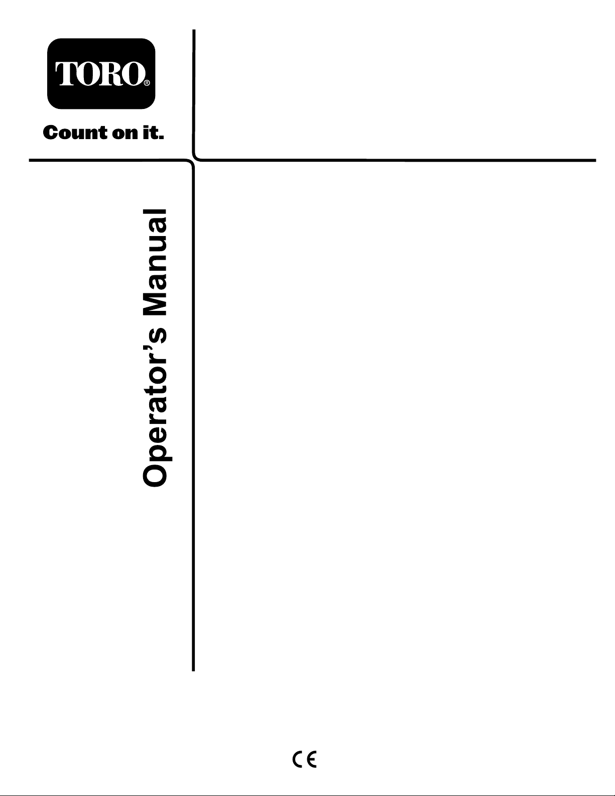
106-6755
1.Enginecoolantunder
pressure.
2.Explosionhazard—read
theOperator'sManual.
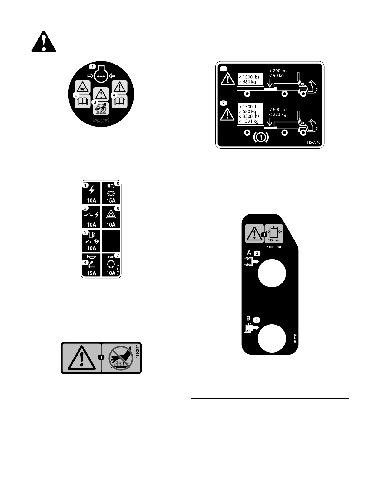
115-7813
1.Poweroutlet—10A5.Lights,brake—15A
2.Switchedpower—10A
3.Fuelpump,supervisor
switch—10A
4.Horn,powerpoint—15A
3.Warning—donottouchthe
hotsurface.
4.Warning—readthe
Operator'sManual.
6.Hazard—10A
7.4WD,Transmission—10A
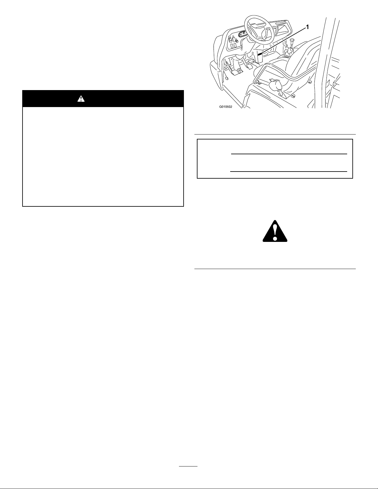
115-7740
1.Warning—maximumtrailerweightis1500lb(680kg),
maximumtongueweightis200lb(90kg).
2.Warning—trailerbrakesarerequiredwhentowinggreater
than1500lb(680kg),maximumtrailerweightwithtrailer
brakesis3500lb(1591kg),maximumtongueweightwith
trailerbrakesis600lb(273kg).
1.Warning—donottouchthehotsurface.
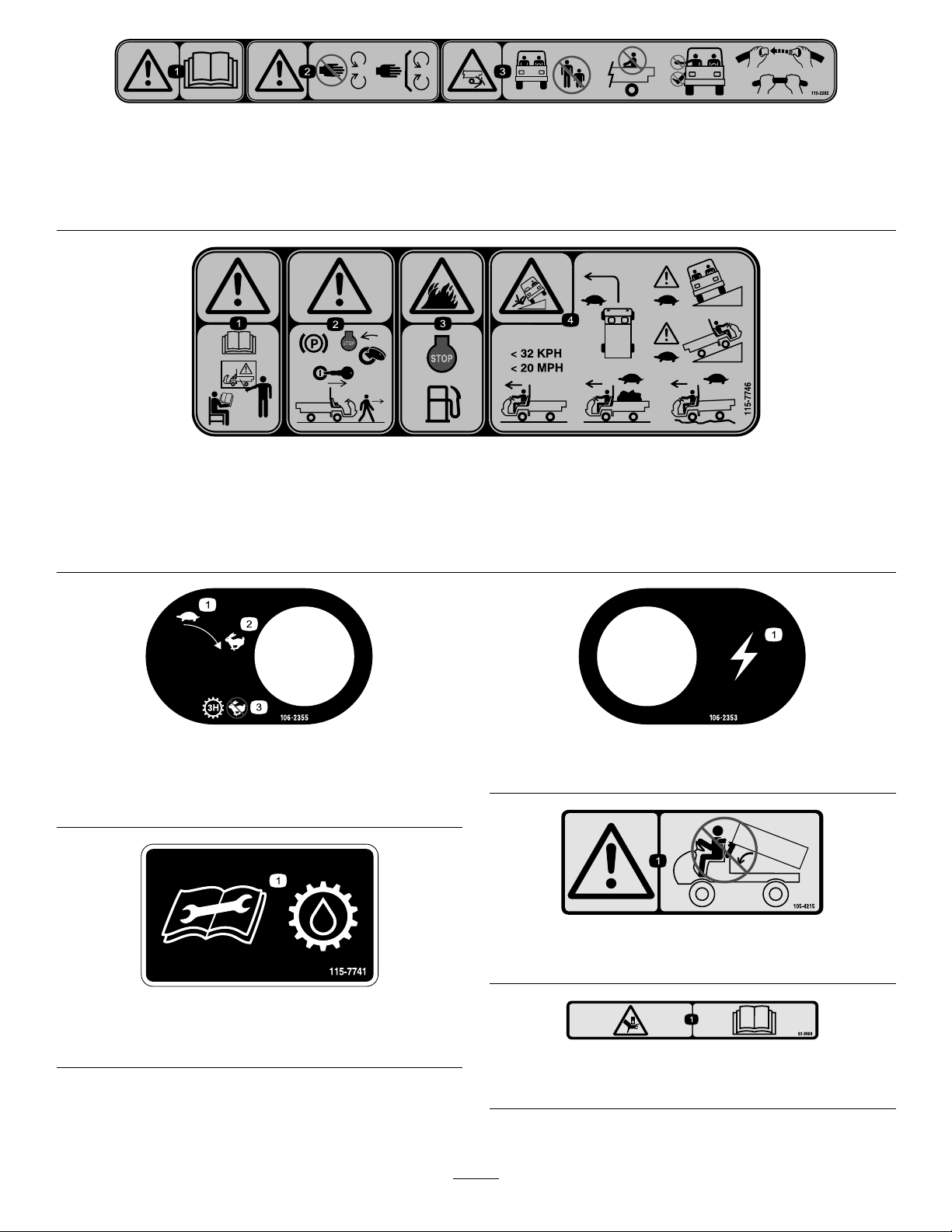
115-7723
1.Warning—thehydraulicoilpressureis124bar(1800psi).
115-2047
2.CouplerA
3.CouplerB
8
Page 9
115-2282
1.Warning—readtheOperator'sManual.
2.Warning—stayawayfrommovingparts,keepallguardsandshieldsinplace.
3.Crushing/dismembermenthazardofbystanders—keepbystandersasafedistancefromthevehicle,donotcarrypassengersin
thecargobed,keeparmsandlegsinsideofthevehicleatalltimes,anduseseatbeltsandhandholds.
115-7746
1.Warning—donotoperatethismachineunlessyouaretrained.
2.Warning—locktheparkingbrake,stoptheengine,and
removetheignitionkeybeforeleavingthemachine.
106-2355
1.Slow
2.Fast
3.Transmission—thirdhigh;
nofastspeed
3.Firehazard—stoptheenginebeforefueling.
4.Tippinghazard—slowdownandturngradually ,usecaution
anddriveslowlywhendrivingonslopes,donotexceed20
mph(32kph),anddriveslowlyoverroughterrainorwhen
carryingafullorheavyload.
106-2353
1.Electricalpowerpoint
105-4215
115-7741
1.ReadtheOperator’sManualbeforeservicingtransmission
uid.
1.Warning—avoidpinchpoints.
93–9868
1.Crushinghazardofhand—readtheOperator’sManual.
9
Page 10
BatterySymbols
93-9899
Someorallofthesesymbolsareonyourbattery
93-9879
1.Storedenergyhazard—readtheOperator'sManual.
1.Explosionhazard
2.Nore,opename,or
smoking.
3.Causticliquid/chemical
burnhazard
4.Weareyeprotection9.Flusheyesimmediately
5.ReadtheOperator's
Manual.
6.Keepbystandersasafe
distancefromthebattery.
7.Weareyeprotection;
explosivegasescan
causeblindnessandother
injuries
8.Batteryacidcancause
blindnessorsevereburns.
withwaterandgetmedical
helpfast.
10.Containslead;donot
discard.
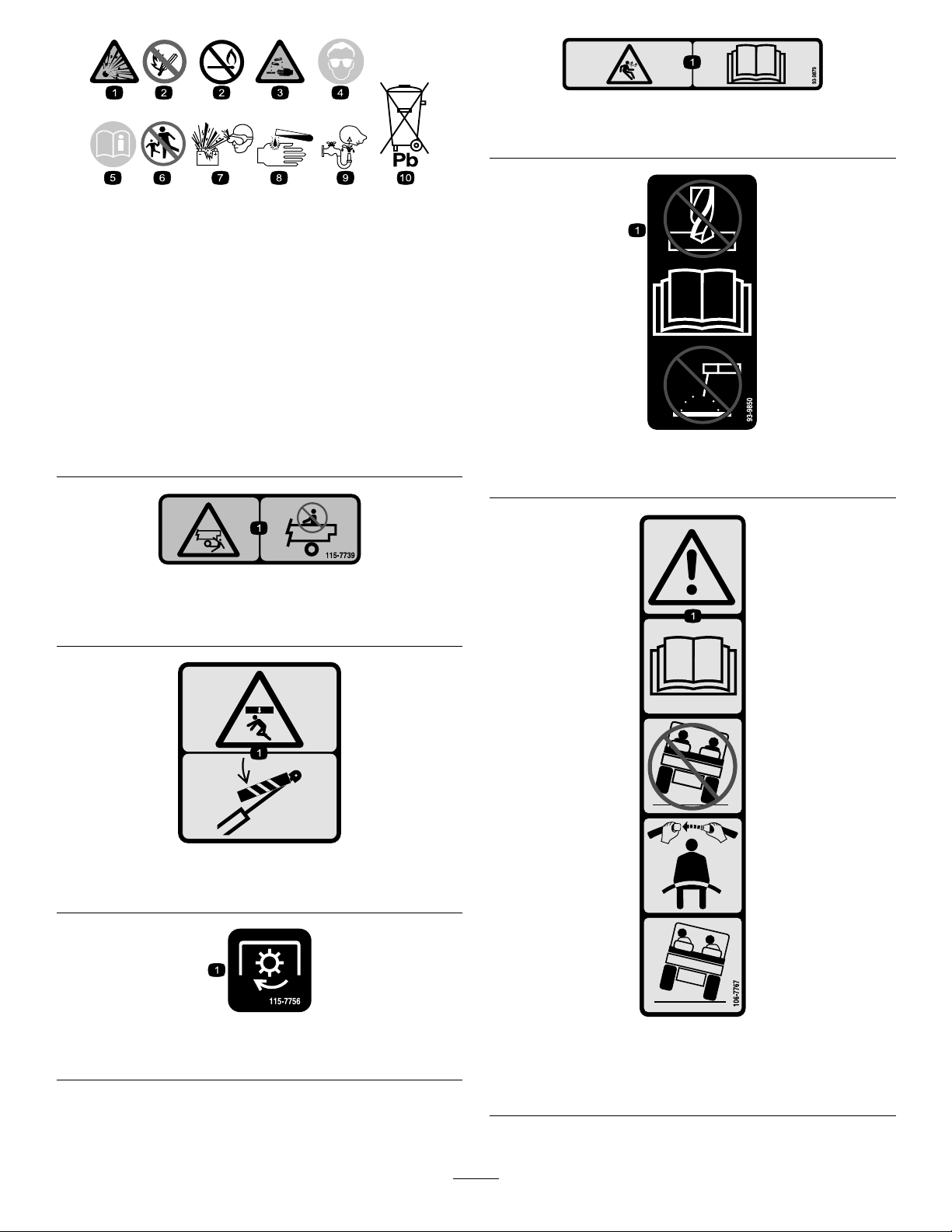
115-7739
1.Falling,crushinghazard,bystanders—noriderson
machine.
93-9850
1.Donotrepairorrevise—readtheOperator'sManual.
93-9899
1.Crushinghazard—installthecylinderlock.
115-7756
1.Highowhydraulics—engaged
106-7767
1.Warning—readtheOperator'sManual;avoidtippingthe
machine;weartheseatbelt;leanawayfromthedirection
themachineistipping.
10
Page 11

106-2377
1.Locked
2.Differentiallock9.Entanglementhazard,shaft—keepbystander'sasafe
3.Unlocked10.Retracthydraulics
4.Hydrauliclock11.Extendhydraulics
5.Engage12.Transmission—highspeed
6.Powertake-off(PTO)
7.Disengage14.Parkingbrake
8.Warning—readtheOperator'sManual.
distancefromthevehicle.
13.Transmission—lowspeed
1.Headlights4.Engine—run
2.Horn5.Engine—start
3.Engine—stop
115-2281
11
Page 12
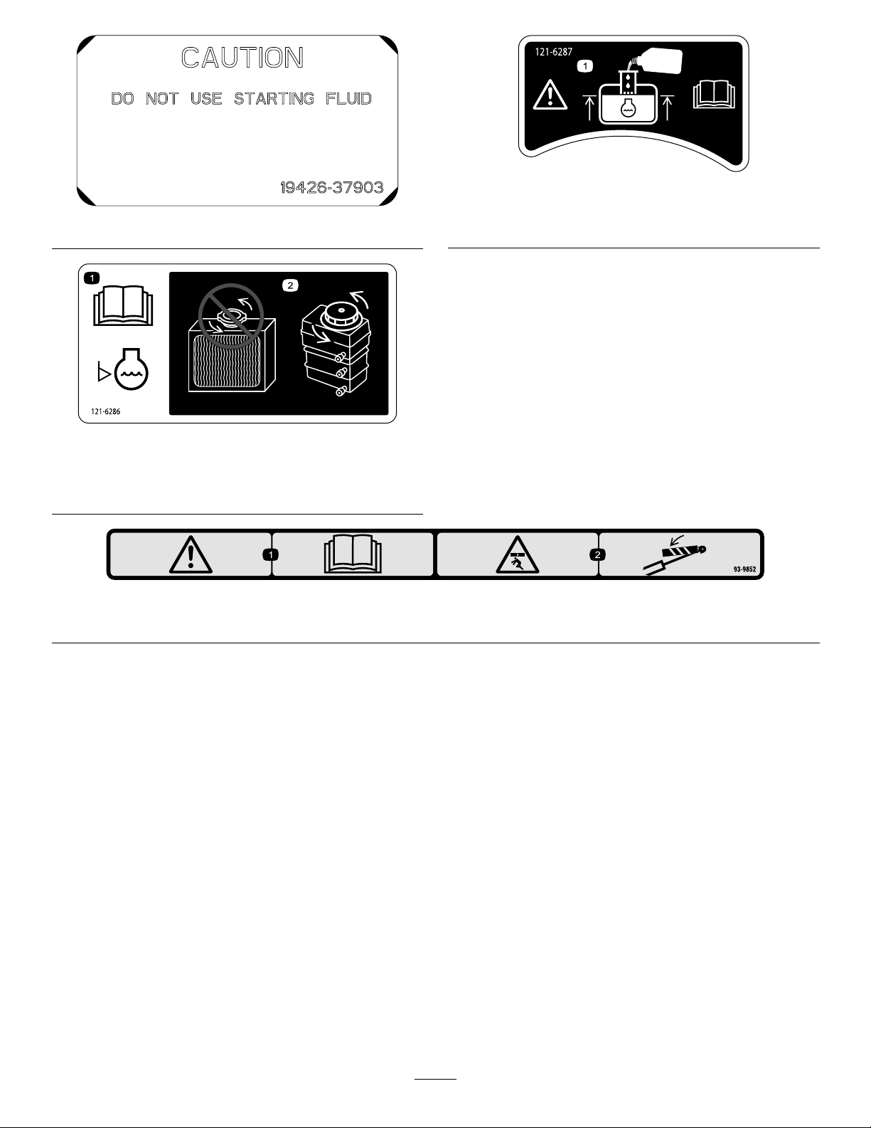
121-6287
110–0806
1.Fillthereservoirwithenginecoolanttothebottomofthe
standpipe.
121-6286
1.ReadtheOperator's
Manualbeforechecking
theenginecoolantlevel.
2.Donotaddenginecoolant
totheradiator;addengine
coolanttothereservoir,
93-9852
1.Warning—readtheOperator’sManual.2.Crushinghazard—installthecylinderlock.
12
Page 13

Setup
LooseParts
Usethechartbelowtoverifythatallpartshavebeenshipped.
ProcedureDescription
1
2
3
Note:Determinetheleftandrightsidesofthemachinefromthenormaloperatingposition.
Steeringwheel
ROPSframe
Bolt(1/2inch)
Nopartsrequired
Qty.
1
InstallingtheSteeringWheel (TCmodelsonly)
Partsneededforthisprocedure:
1
Steeringwheel
Use
1
1
6
–
Installthesteeringwheel(TCmodels
only).
MounttheRolloverProtectionSystem
(ROPS).
Checktheengineoil,the
transaxle/hydraulicuid,andthe
brakeuidlevels.
Procedure
1.Releasethetabsonthebackofthesteeringwheelthat
holdthecentercoverinplace,andremovethecover
fromthehubofthesteeringwheel.
2.Removethelocknutandwasherfromthesteeringshaft.
3.Slidethesteeringwheelandwasherontotheshaft.
Alignthesteeringwheelontheshaftsothatthecross
beamishorizontalwhenthetiresarepointedstraight
aheadandthethickerspokeofthesteeringwheelis
downward.
Note:Thedustcoverispositionontothesteering
shaftatthefactory.
4.Securethesteeringwheeltotheshaftwiththelocknut
(Figure3).Torquethelocknutto24to29N-m(18
to22ft-lb)
Figure3
1.Steeringshaft
2.Dustcover6.Locknut
3.Steeringwheel7.Cover
4.Tabslotsinwheel8.Tabsincover
5.Alignthetabsofthecoverwiththeslotsinthesteering
wheel,andsnapthecoverontothesteering-wheelhub
(Figure3).
5.Washer
13
Page 14
2
3
InstallingtheRollover
ProtectionSystem
(ROPS)—TCmodelsonly
Partsneededforthisprocedure:
1
ROPSframe
6
Bolt(1/2inch)
Procedure
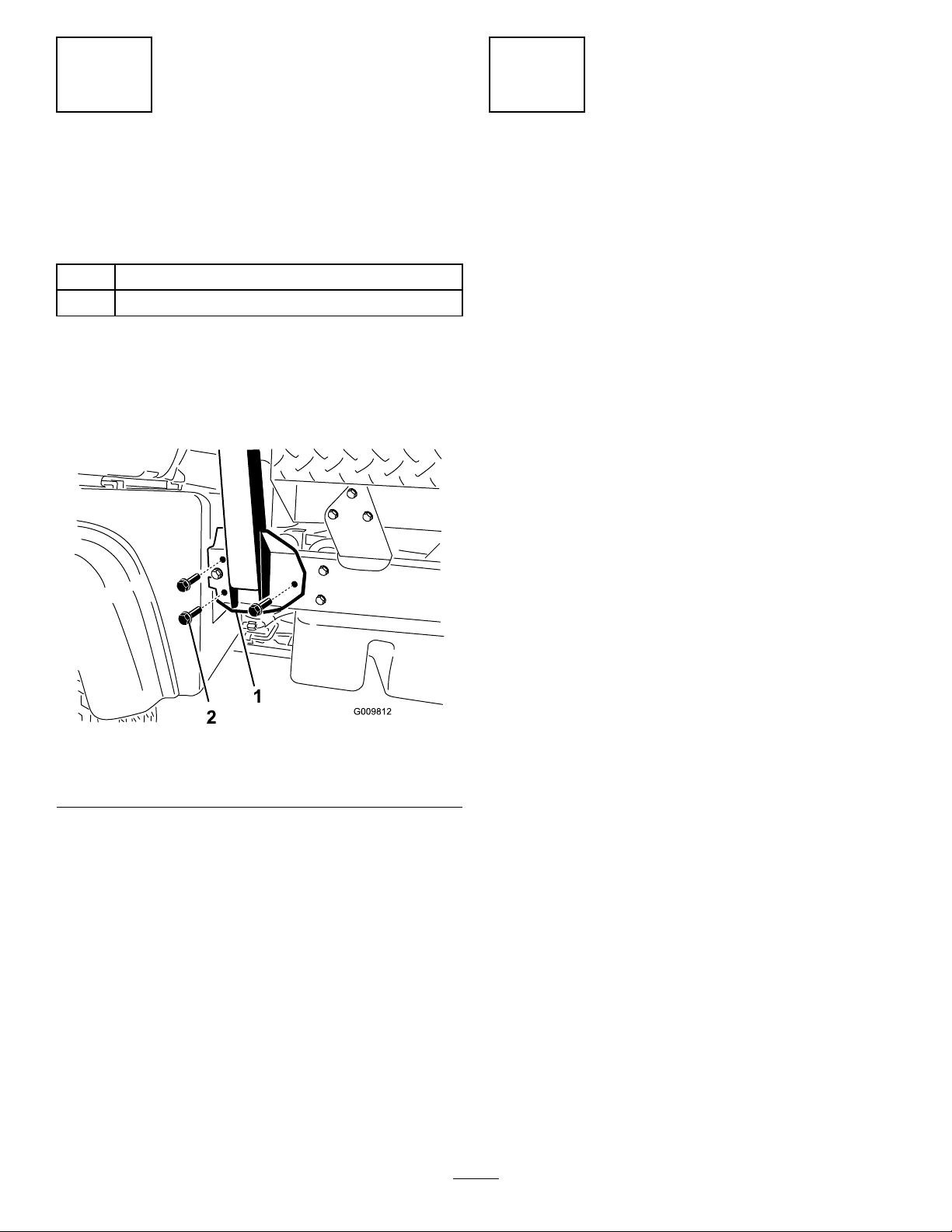
1.AligneachsideoftheROPSwiththemountingholes
intheframeateachsideofthevehicleasshownin
Figure4.
CheckingtheFluidLevels
NoPartsRequired
Procedure
1.Checktheengine-oillevelbeforeandaftertheengine
isrststarted;refertoCheckingtheEngine-oilLevel
(page20).
2.Checkthetransaxle/hydraulic-uidlevelbefore
theengineisrststarted;referto
Transaxle/Hydraulic-uidLevel(page23).
3.Checkthebrake-uidlevelbeforetheengineisrst
started;refertoCheckingtheBrake-uidLevel(page
25).
Checkingthe
Figure4
1.ROPS-mountingbracket2.Flangedbolts(1/2x1-1/4
2.SecureeachsideoftheROPStoframewith3anged
bolts(1/2x1-1/4inch),andtightentheboltsto115
N-m(85ft-lb).
inch)
14
Page 15
ProductOverview
Controls
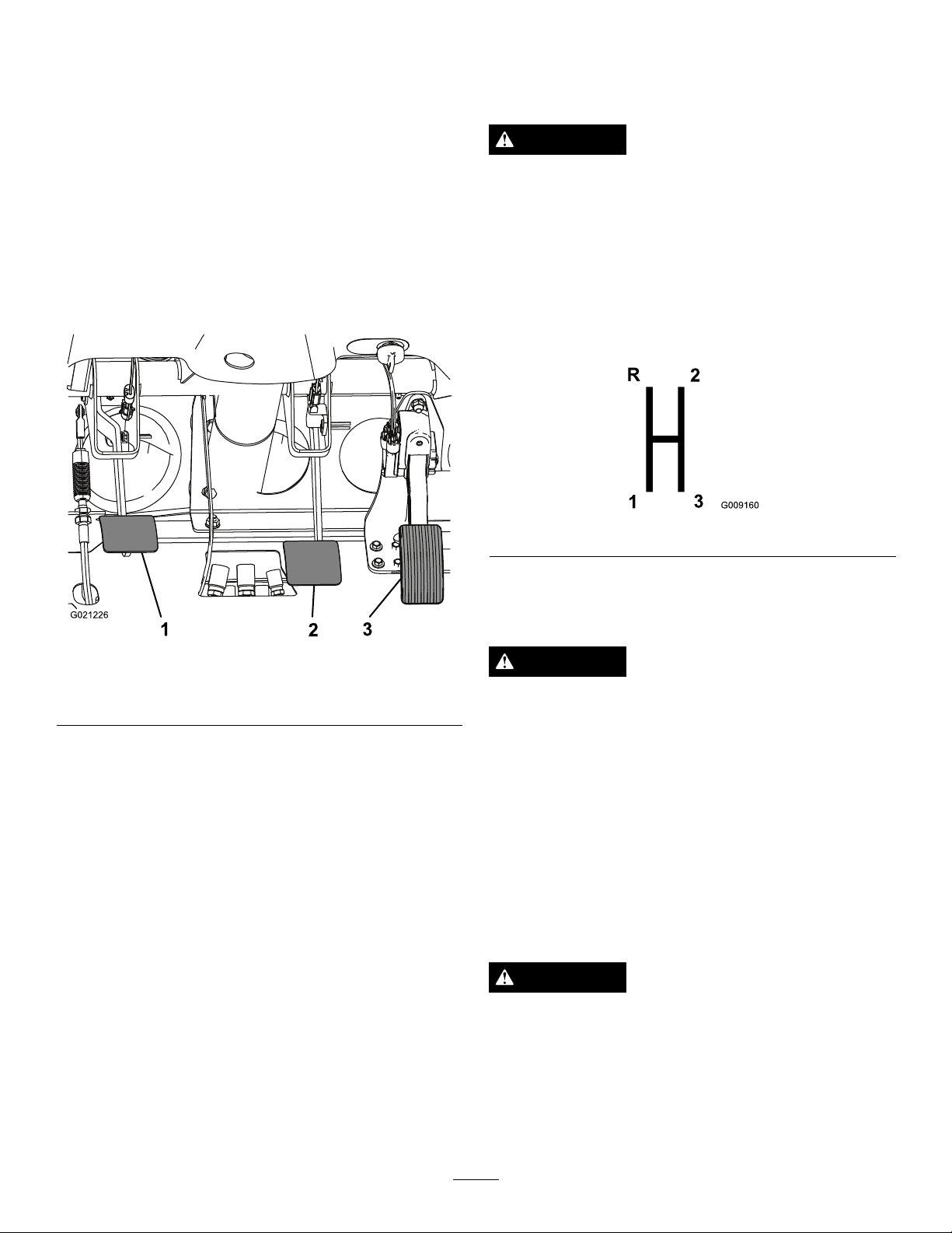
BrakePedal
Thebrakepedal(Figure5)isusedtoapplyservicebrakes
tostoporslowthemachine.
Note:Determinetheleftandrightsidesofthemachine
fromthenormaloperatingposition.
AcceleratorPedal
Theacceleratorpedal(Figure5)givestheoperatortheability
tovarytheengineandgroundspeedofthemachinewhen
thetransmissionisingear.Pressingthepedalincreasesthe
enginerpmandgroundspeed.Releasingthepedaldecreases
theenginerpmandgroundspeedofthemachine.
CAUTION
Wornormaladjustedbrakesmayresultinpersonal
injury.Ifthebrakepedaltravelstowithin3.8cm
(1-1/2inches)ofthemachineoorboard,the
brakesmustbeadjustedorrepaired.
Gear-shiftLever
Fullypresstheclutchpedalandmovetheshiftlever(Figure
6)intothedesiredgearselection.Adiagramoftheshift
patternisshownbelow.
Figure6
Important:Donotshiftthetransaxletothereverseor
forwardgearunlessthevehicleisstandingstill.Damage
tothetransaxlemayoccur.
Figure5
1.Clutchpedal
2.Brakepedal
3.Acceleratorpedal
ClutchPedal
Theclutchpedal(Figure5)mustbefullypressedtodisengage
clutchwhenstartingtheengineorshiftingtransmissiongears.
Releasethepedalsmoothlywhenthetransmissionisingear
topreventunnecessarywearonthetransmissionandother
relatedparts.
Important:Donotridetheclutchpedalduring
operation.Theclutchpedalmustbefullyoutorthe
clutchwillslipcausingheatandwear.Neverhold
themachinestoppedonahillusingtheclutchpedal.
Damagetotheclutchmayoccur.
CAUTION
Downshiftingfromtoohighaspeedcancausethe
rearwheelstoskidresultinginlossofmachine
controlaswellasclutchand/ortransmission
damage.Shiftsmoothlytoavoidgrindinggears.
DifferentialLock
Thedifferentiallockallowsrearaxletobelockedfor
increasedtraction.Thedifferentiallock(Figure7)maybe
engagedwhenthemachineisinmotion.Movethelever
forwardandtotherighttoengagethelock.
Note:Machinemotionplusaslightturnisrequiredto
engageordisengagedifferentiallock.
CAUTION
Turningwiththedifferentiallockoncanresult
inlossofmachinecontrol.Donotoperatewith
differentiallockonwhenmakingsharpturnsorat
highspeeds;refertoAdjustingDifferential-lock
Cable(page47)
.
15
Page 16
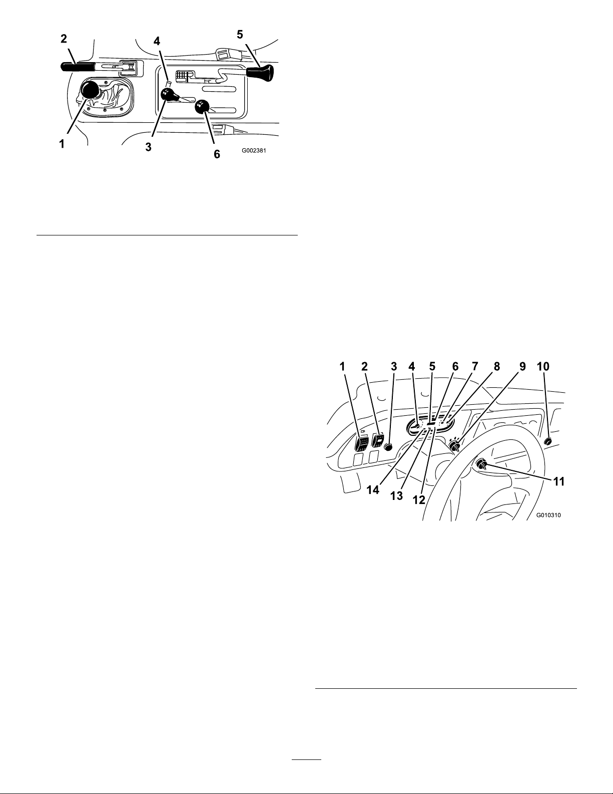
Figure7
1.Gear-shiftlever4.Hydraulic-liftlock
2.Parkingbrake
3.Hydraulic-bedlift6.High–lowrangeshifter
5.Differentiallock
•Shiftonlyonlevelground.
•Presstheclutchpedalfully.
•MovetheleverfullyforwardforHighandfullyrearward
forLow .
Highisforhigherspeeddrivingonlevel,drysurfaceswith
lightloads.
Lowisforlow-speeddriving.Usethisrangewhengreater
thannormalpowerorcontrolisrequired.Forexample,
steepgrades,difcultterrain,heavyloads,slowspeedbut
high-enginespeed(spraying).
Important:ThereisalocationbetweenHighandLow
inwhichthetransaxleisinneitherrange.Donotuse
thispositionasaneutralpositionbecausethevehicle
couldmoveunexpectedlyiftheHigh–Lowshifteris
bumpedandthegear-shiftleverisingear.
ParkingBrake
Whenevertheengineisshutoff,settheparkingbrake(Figure
7)inordertopreventthemachinefromaccidentallymoving.
•Tosettheparkingbrake,pullbackonthelever.
•Torelease,pushtheleverforward.
Note:Releasetheparkingbrakebeforemovingthe
machine.
Ifyouparkthemachineonasteepgrade,settheparking
brake,shiftthetransmissionintorstgearonauphillgrade
orreversegearonadownhillgrade,andplacechocksatthe
downhillsideofthewheels.
HydraulicLift
Thehydraulicliftraisesandlowersthebed.Moveitrearward
toraisethebed,andforwardtolowerit(Figure7).
Important:Whenloweringthebed,holdtheleverin
theforwardpositionfor1or2secondsafterthebed
contactstheframetosecureitintheloweredposition.
Donotholdthehydraulicliftineithertheraiseorlower
position,formorethan5seconds,oncethecylinders
havereachedtheendoftheirtravel.
Hydraulic-liftLock
Thehydraulic-liftlocklockstheliftlever,sothehydraulic
cylindersdonotoperatewhenthemachineisnotequipped
withabed(Figure7).ItalsolockstheliftleverintheOn
positionwhenusingthehydraulicsforattachments.
High–LowRangeShifter
IgnitionSwitch
Usetheignitionswitch(Figure8)tostartandstopthe
engine.Ithas3positions:Off,On,andStart.Rotatethekey
clockwisetotheStartpositiontoengagethestartermotor.
Releasethekeywhentheenginestarts.Thekeywillmove
automaticallytotheOnposition.Toshuttheengineoff,
rotatethekeycounterclockwisetotheOffposition.
Figure8
1.Lightswitch8.Fuelgauge
2.High-ow-hydraulics
switch
(TCmodelsonly)
3.Horn
(TCmodelsonly)
4.Tachometer11.3rdhighlockoutswitch
5.Hourmeter
6.Speedometer13.Glow-plugindicator
7.Coolant-temperature
gaugeandlight
9.Ignitionswitch
10.Powerpoint
12.Oilpressurewarninglight
14.Chargeindicator
Thehigh–lowrangeshifteradds3additionalspeedsfor
precisespeedcontrol(Figure7).
•Themachinemustbecompletelystoppedbeforeshifting
betweentheHighandLowrange.
16
Page 17
HourMeter
Thehourmeterindicatesthetotalhoursofmachine
operation.Thehourmeter(Figure8)startstofunction
wheneverthekeyswitchisrotatedtotheOnpositionorif
theengineisrunning.
•Applytheparkingbrake.
•TurntheignitionkeytotheOn/Preheatposition,butdo
notstarttheengine.Thecoolanttemperature,charge
indicator,andoil-pressurelightsshouldglow .Ifanylight
doesnotfunction,eitherabulbisburnedoutorthereisa
malfunctioninthesystemwhichmustberepaired.
Speed-limiterSwitch
Movethespeed-limiterswitch(Figure8)totheslowposition
andremovethekey.Theswitchlimitstheengineto2,200
rpmwhenthemachineisinthirdgearintheHighrange,
whichlimitsthetopspeedto21km/h(13mph).
LightSwitch
Pushthelightswitch(Figure8)totoggletheheadlightson
oroff.
Oil-pressure-warningLight
Theoil-pressure-warninglightglows(Figure8)ifthe
engine-oilpressuredropsbelowasafelevelwhiletheengine
isrunning.Ifthelightickersorremainson,stopthevehicle,
turnofftheengine,andchecktheoillevel.Iftheoillevelis
low,butaddingoildoesnotcausethelighttogooutwhen
theengineisrestarted,turntheengineoffimmediatelyand
contactyourlocalTorodistributorforassistance.
Checktheoperationofwarninglightsasfollows:
1.Applytheparkingbrake.
2.TurntheignitionkeytotheOn/Preheatposition,but
donotstarttheengine.
FuelGauge
Thefuelgaugeshowstheamountoffuelinthetank.It
operatesonlywhenignitionswitchisintheOnposition
(Figure8).Redindicateslowfuellevelandblinkingred
indicatesnearempty.
High-owHydraulicsSwitch(TC
modelsonly)
Turnontheswitchtoactivatethehigh-owhydraulics
Figure8).
(
HornButton(TCmodelsonly)
Pressingthehornbuttonactivatesthehorn(Figure8).
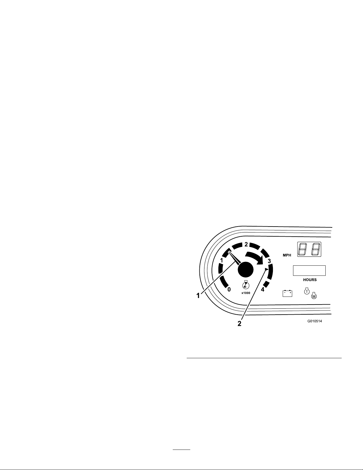
Tachometer
Registersthespeedoftheengine(Figure8andFigure9).The
whitetriangleindicatesdesiredspeedforPTOoperation
(Figure9).
Note:Theoilpressurelightshouldglowred.Ifthe
lightdoesnotfunction,eitherabulbisburnedoutor
thereisamalfunctioninthesystemwhichmustbe
repaired.
Note:Ifenginewasjustturnedoff,itmaytake1to
2minutesforthelighttocomeon.
Coolant-temperatureGaugeandLight
Registersthecoolanttemperatureintheengine.Operates
onlywhentheignitionswitchisinOnposition(Figure8).
Theindicatorlightilluminatesblinkingrediftheengine
overheats.
ChargeIndicator
Illuminateswhenbatteryisbeingdischarged.Ifthelight
illuminatesduringoperation,stopthemachine,turnoffthe
engine,andcheckforpossiblecauses,suchasthealternator
belt(
Figure8).
Important:Ifthealternatorbeltislooseorbroken,do
notoperatethemachineuntiladjustmentorrepairis
complete.Failuretoobservethisprecautionmayresult
indamagetotheengine.
Checktheoperationofwarninglightsasfollows:
Figure9
1.Speedoftheengine2.3300rpmfor540rpmPTO
operation
Check-engineLight
Thelight(Figure8)willilluminatetonotifyoperatorofa
enginemalfunction.
Speedometer
Registersthegroundspeedofthemachine(Figure8).The
speedometerisinmphbutcaneasilyconvertedtokm/h;
refertoConvertingtheSpeedometer(page53).
17
Page 18
PowerPoint
Usethepowerpoint(Figure8)topoweroptional12volt
electricalaccessories.
Specications
Note:Specicationsanddesignaresubjecttochange
withoutnotice.
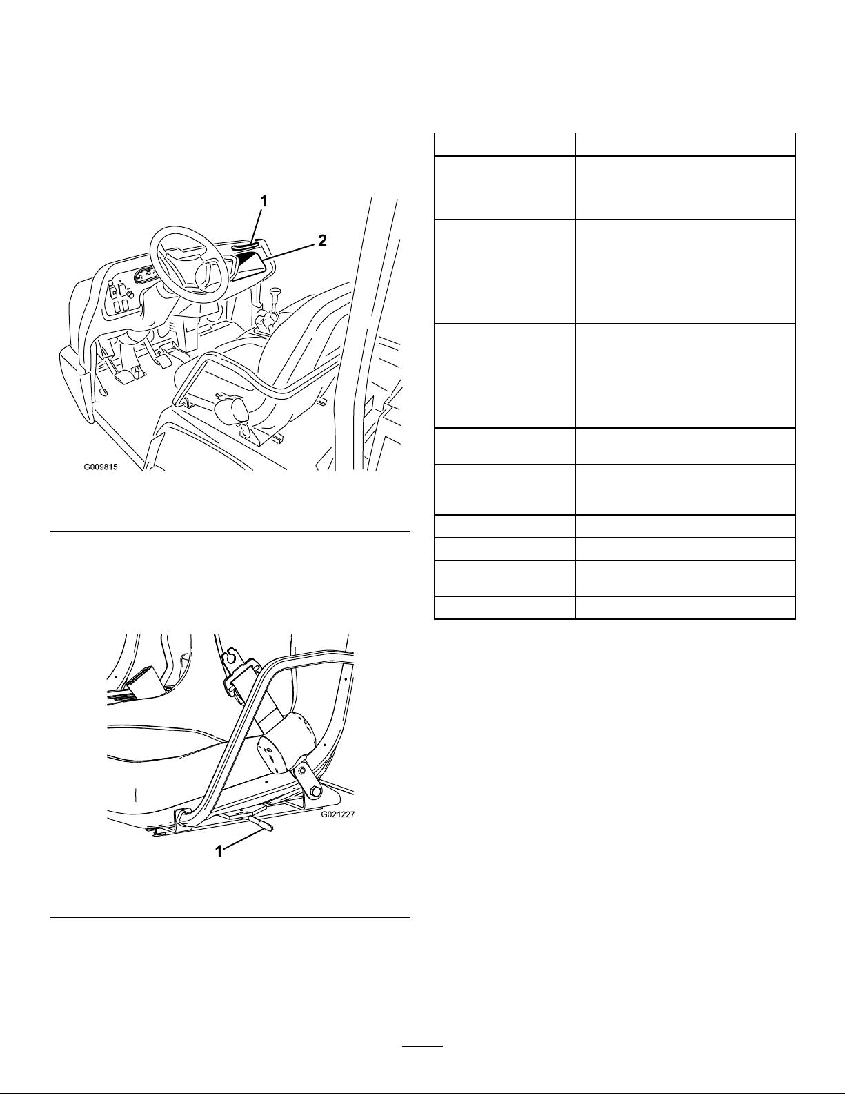
PassengerHandHold
Thepassengerhandholdislocatedonthedashboard(Figure
10).
Figure10
1.Passengerhandhold
2.Storagecompartment
Seat-adjustingLever
Theseatscanbeadjustedforeandaftforoperatorcomfort
(Figure11).
Dimensions
OverallWidth160cm(63inches)
Withoutbed:326cm(128inches)
OverallLength
BaseWeight(Dry)
RatedCapacity
(includes91kg(200lb)
operator,91kg(200lb)
passengerandloaded
attachment)
MaximumGross
VehicleWeight
TowCapacityTongueweight:272kg(600lb)
GroundClearance18cm(7inches)withnoload
WheelBase
WheelTread(center
linetocenterline)
Height
Withfullbed:331cm(130inches)
With2/3bedinrear-mountinglocation:
346cm(136inches)
Model07383—736kg(1623lb)
Model07384—885kg(1951lb)
Model07384H—885kg(1951lb)
Model07384TC—921.6kg(2032lb)
Model07386—912kg(2010lb)
Model07386H—912kg(2010lb)
Model07386TC—948kg(2091lb)
Model07383—1623kg(3577lb)
Model07384—1474kg(3249lb)
Model07384H—1474kg(3249lb)
Model07384TC—1437kg(3168lb)
Model07386—1447kg(3190lb)
Model07386H—1447kg(3190lb)
Model07386TC—1410kg(3109lb)
2359kg(5200lb)
Maximumtrailerweight:1587kg
(3,500lb)
118cm(70inches)
Front:117cm(46inches)
Rear:121cm(48inches)
191cm(75inches)totopofROPS
1.Seat-adjustinglever
Attachments/Accessories
AselectionofToroapprovedattachmentsandaccessoriesis
availableforusewiththemachinetoenhanceandexpand
itscapabilities.ContactyourAuthorizedServiceDealeror
Distributororgotowww .Toro.comforalistofallapproved
attachmentsandaccessories.
Figure11
18
Page 19

Operation
Note:Determinetheleftandrightsidesofthemachine
fromthenormaloperatingposition.
CAUTION
Beforeservicingormakingadjustmentstothe
machine,stoptheengine,settheparkingbrake,
andremovethekeyfromtheswitch.Removeany
loadmaterialfromthebedorotherattachment
beforeworkingunderaraisedbed.Neverwork
underaraisedbedwithoutpositioningthesafety
supportonafullyextendedcylinderrod.
OperatingtheCargoBox
Figure12
1.Cargoboxlever
Note:Centerloadsinthecargoboxifpossible.
Note:Removeallcargofromtheboxbeforeliftingthebox
uptoservicethemachine.
RaisingtheCargoBox
WARNING
Drivingthemachinewiththecargoboxraisedmay
causethemachinetotiporrolleasier.Thebox
structuremaybecomedamagedifyouoperatethe
machinewiththeboxraised.
•Onlyoperatethemachinewhenthecargobox
isdown.
•Afteremptyingthecargobox,lowerit.
CAUTION
Ifaloadisconcentratednearthebackofthecargo
boxwhenyoureleasethelatches,theboxmay
unexpectedlytipopeninjuringyouorbystanders.
LoweringtheBox
WARNING
Theweightoftheboxmaybeheavy.Handsor
otherbodypartscouldbecrushed.
Keephandsandotherbodypartsclearwhen
loweringthebox.
Movetheleverforwardtolowerthecargobox(Figure12).
OpeningtheTailgate
1.Ensurethatthecargoboxisloweredcompletely.
2.Openthelatchesontheleftandrightsideofthecargo
boxandlowerthetailgate(Figure13).
•Centerloadsinthecargoboxifpossible.
•Holdthecargoboxdownandensurethatno
oneisleaningovertheboxorstandingbehindit
whenreleasingthelatches.
•Removeallcargofromtheboxbeforeliftingthe
boxuptoservicethemachine.
Movetheleverbackwardtoraisethecargobox(Figure12).
19
Page 20

G016095
isatorbelowtheAddmarkonthedipstick,addoiltobring
1
2
G021228
theoilleveltotheFullmark.Donotoverlltheengine
withoil.IftheoillevelisbetweentheFullandAddmarks,
noadditionaloilisrequired.
1.Positionthemachineonalevelsurface.
Figure13
1.Latchhandle3.Latchpin
2.Latchgate
CheckingtheEngine-oilLevel
ServiceInterval:Beforeeachuseordaily
2.Removethedipstick(
cleanrag.
1.Fillercap
2.Dipstick
Figure15)andwipeitwitha
Figure15
Engineoiltype:DetergentengineoilAPISJorhigher
Engine-oilviscosity:10W-30;Chooseanengine-oil
viscosityaccordingtotheambient-airtemperaturetothe
tableinFigure14.
Figure14
Theengineisshippedwithoilinthecrankcase;however,you
shouldchecktheoillevelbeforeandaftertheengineisrst
started.
Note:Thebesttimetochecktheengineoiliswhenthe
engineiscoolbeforeithasbeenstartedfortheday.Ifithas
alreadybeenrun,allowtheoiltodrainbackdowntothe
sumpforatleast10minutesbeforechecking.Iftheoillevel
3.Insertthedipstickintothetubeandmakesureitis
seatedfully(Figure15).
4.Removedipstickandchecktheleveloftheoil(Figure
15).
5.Iftheoillevelislow ,removethellercap(Figure15),
andaddenoughoiltoraisetheleveltotheFullmark
onthedipstick.
Note:Whenaddingoil,removedipsticktoallow
properventing.Pourtheoilslowlyandcheckthelevel
oftenduringthisprocess.Donotoverlltheengine
withoil.
Important:Whenaddingengineoilorlling
oil,theremustbeclearancebetweentheoilll
deviceandtheoilllholeinthevalvecoveras
shownin
Figure16.Thisclearanceisnecessary
topermitventingwhenlling,whichpreventsoil
fromoverrunningintothebreather.
20
Page 21

DANGER
Incertainconditions,gasolineisextremely
ammableandhighlyexplosive.Areorexplosion
fromgasolinecanburnyouandothersandcan
damageproperty.
•Fillthefueltankoutdoors,inanopenarea,
whentheengineiscold.Wipeupanygasoline
thatspills.
•Neverllthefueltankinsideanenclosedtrailer.
•Donotllthefueltankcompletelyfull.Add
gasolinetothefueltankuntilthelevelis6to13
mm(1/4to1/2inch)belowthebottomofthe
llerneck.Thisemptyspaceinthetankallows
gasolinetoexpand.
Figure16
1.Noteclearance
6.Installthedipstickrmlyinplace(Figure15).
RespondingtoaCheck-engine Light
Note:Enginefaultcodeinformationcanonlybeaccessed
byyourTorocommercialproductsservicestaff.
1.Parkthevehicleinasafemannerassoonpossible.
2.ContactyourauthorizedToroservicedealer.
Note:Scheduleaservicecallorbringthemachinein
tobeanalyzed.
AddingFuel
•Forbestresults,useonlyclean,fresh(lessthan30days
old),unleadedgasolinewithanoctaneratingof87or
higher((R+M)/2ratingmethod).
•Ethanol:Gasolinewithupto10%ethanol(gasohol)
or15%MTBE(methyltertiarybutylether)byvolume
isacceptable.EthanolandMTBEarenotthesame.
Gasolinewith15%ethanol(E15)byvolumeisnot
approvedforuse.Neverusegasolinethatcontains
morethan10%ethanolbyvolume,suchasE15
(contains15%ethanol),E20(contains20%ethanol),or
E85(containsupto85%ethanol).Usingunapproved
gasolinemaycauseperformanceproblemsand/orengine
damagewhichmaynotbecoveredunderwarranty.
•Donotusegasolinecontainingmethanol.
•Donotstorefueleitherinthefueltankorfuelcontainers
overthewinterunlessafuelstabilizerisused.
•Donotaddoiltogasoline.
•Neversmokewhenhandlinggasoline,andstay
awayfromanopenameorwheregasoline
fumesmaybeignitedbyaspark.
•Storegasolineinanapprovedcontainerand
keepitoutofthereachofchildren.Neverbuy
morethana30-daysupplyofgasoline.
•Donotoperatewithoutentireexhaustsystemin
placeandinproperworkingcondition.
DANGER
Incertainconditionsduringfueling,static
electricitycanbereleasedcausingasparkwhich
canignitethegasolinevapors.Areorexplosion
fromgasolinecanburnyouandothersandcan
damageproperty.
•Alwaysplacegasolinecontainersontheground
awayfromyourvehiclebeforelling.
•Donotllgasolinecontainersinsideavehicleor
onatruckortrailerbedbecauseinteriorcarpets
orplastictruckbedlinersmayinsulatethe
containerandslowthelossofanystaticcharge.
•Whenpractical,removegas-poweredequipment
fromthetruckortrailerandrefueltheequipment
withitswheelsontheground.
•Ifthisisnotpossible,thenrefuelsuch
equipmentonatruckortrailerfromaportable
container,ratherthanfromagasolinedispenser
nozzle.
•Ifagasolinedispensernozzlemustbeused,
keepthenozzleincontactwiththerimofthe
fueltankorcontaineropeningatalltimesuntil
fuelingiscomplete.
21
Page 22

WARNING
Gasolineisharmfulorfatalifswallowed.Long-term
exposuretovaporscancauseseriousinjuryand
illness.
•Avoidprolongedbreathingofvapors.
•Keepfaceawayfromnozzleandgastankor
conditionerbottleopening.
•Avoidcontactwithskin;washoffspillagewith
soapandwater.
UsingStabilizer/Conditioner
Useafuelstabilizer/conditionerinthemachinetoprovide
thefollowingbenets:
•Keepsgasolinefreshduringstorageof90daysorless.
Forlongerstorageitisrecommendedthatthefueltank
bedrained.
•Cleanstheenginewhileitruns
•Eliminatesgum-likevarnishbuildupinthefuelsystem,
whichcauseshardstarting
Important:Donotusefueladditivescontaining
methanolorethanol.
Addthecorrectamountofgasstabilizer/conditionerto
thegas.
Note:Afuelstabilizer/conditionerismosteffective
whenmixedwithfreshgasoline.Tominimizethechance
ofvarnishdepositsinthefuelsystem,usefuelstabilizer
atalltimes.
3.Fillthetanktoaboutoneinchbelowthetopofthe
tank,(bottomofthellerneck),theninstallthecap.
Note:Donotoverllthefueltank.
4.Wipeupanyfuelthatmayhavespilledtopreventa
rehazard.
CheckingtheCoolantLevel
ServiceInterval:Beforeeachuseordaily
Coolingsystemcapacity:3.7L(4USqt)
Coolanttype:a50/50solutionofwaterandpermanent
ethylene-glycolantifreeze.
CAUTION
Iftheenginehasbeenrunning,thepressurized,hot
coolantcanescapeandcauseburns.
•Donotopentheradiatorcap.
•Allowtheenginetocoolatleast15minutesor
untiltheradiatorcapiscoolenoughtotouch
withoutburningyourhand.
•Usearagwhenopeningthereservetankcap,
andopenthecapslowlytoallowsteamto
escape.
•Donotcheckthecoolantlevelattheradiator;
onlycheckthecoolantlevelatthereservetank.
FillingtheFuelTank
1.Cleantheareaaroundthefuel-tankcap.
2.Removethefuel-tankcap(
Figure17
1.Fuel-tankcap
Figure17).
1.Parkthemachineonalevelsurface.
2.Checkthecoolantlevelinsidethereservetank(Figure
18).
Note:Thecoolantshouldbeuptothebottomofthe
llerneckwhentheengineiscold.
22
Page 23

Figure18
Checkingthe
Transaxle/Hydraulic-uid
Level
ServiceInterval:Beforeeachuseordaily(checktheuid
levelbeforetheengineisrststartedand
every8hoursordaily ,thereafter.)
Transaxleuidtype:DexronIIIATF
1.Positionthemachineonalevelsurface.
2.Cleantheareaaroundthedipstick(Figure19).
1.Reservetank-cap
2.Reservetank
3.Ifcoolantislow ,removethereservetankcapandadda
50/50mixtureofwaterandpermanentethylene-glycol
antifreeze.
Note:Donotoverllthereservetankwithcoolant.
4.Installthereserve-tankcap.
Figure19
1.Dipstick
3.Unscrewthedipstickfromthetopofthetransaxleand
wipeitwithacleanrag.
4.Screwthedipstickintothetransaxleandensurethat
itisfullyseated.
5.Unscrewthedipstickandchecktheuidlevel.
Note:Theuidshouldbeuptotopoftheatportion
ofthedipstick.
6.Ifthelevelislow ,addenoughofthespecieduidto
achievetheproperlevel.
23
Page 24

CheckingtheHighFlow
Hydraulic-uidLevel(TC
modelsonly)
4.Insertthedipstickintothellerneck,thenremoveit
andchecktheuidlevel.
Note:Theuidlevelshouldbebetweenthe2marks
onthedipstick.
ServiceInterval:Beforeeachuseordaily(checkthelevelof
hydraulicuidbeforetheengineisrst
started,anddailythereafter)
Hydraulic-uidtype:T oroPremiumAllSeason
HydraulicFluid(Availablein5gallonpailsor55gallon
drums.SeepartscatalogorTorodistributorforpart
numbers.)
Alternateuids:IftheTorouidisnotavailable,another
conventionalpetroleum–baseduidmaybeusedprovided
itmeetsthefollowingmaterialpropertiesandindustry
specications.Consultwithyourlubricantdistributorto
identifyasatisfactoryproduct.
Note:Torowillnotassumeresponsibilityfordamage
causedbyimpropersubstitutions,souseonlyproducts
fromreputablemanufacturerswhowillstandbehindtheir
recommendation.
HighViscosityIndex/LowPourPointAntiwear
HydraulicFluid,ISOVG46
MaterialProperties:
•Viscosity—ASTMD445cSt@40ºC:44to48/cSt@
100ºC:7.9to8.5
•ViscosityIndex,ASTMD2270—140to152
•PourPoint,ASTMD97—-35ºFto-46ºF
•FZG,Failstage—11orbetter
•Watercontent(newuid)—500ppm(maximum)
IndustrySpecications:
VickersI-286-S,VickersM-2950-S,DenisonHF-0,Vickers
35VQ25(EatonATS373-C)
1.Cleantheareaaroundthellerneckandthecapofthe
hydraulictank(
2.Removethecapfromthellerneck.
Figure20).
5.Ifthelevelislow ,addtheappropriateuidtoraise
theleveltotheuppermark;refertoChangingthe
High-owHydraulicuidandFilter(TCmodelsonly)
(page55).
6.Installthedipstickandcapontothellerneck.
7.Starttheengineandturnontheattachment.
Note:Letthemrunforabout2minutestopurgeair
fromthesystem.
Important:Themachinemustberunningbefore
startingthehigh-owhydraulics.
8.Stoptheengineandattachmentandcheckforleaks.
WARNING
Hydraulicuidescapingunderpressurecan
penetrateskinandcauseinjury.
•Makesureallhydraulicuidhosesand
linesareingoodconditionandallhydraulic
connectionsandttingsaretightbefore
applyingpressuretothehydraulicsystem.
•Keepyourbodyandhandsawayfrom
pinholeleaksornozzlesthatejecthigh
pressurehydraulicuid.
•Usecardboardorpapertondhydraulic
leaks.
•Safelyrelieveallpressureinthehydraulic
systembeforeperforminganyworkonthe
hydraulicsystem.
•Seekimmediatemedicalattentionifuid
isinjectedintoyourskin.
Figure20
1.Cap
3.Removethedipstick(Figure20)fromthellerneck
andwipeitwithacleanrag.
Checkingthe
Front-differential-oilLevel
(4-wheeldrivemodelsonly)
ServiceInterval:Every100hours/Monthly(whichever
comesrst)
Differential-oiltype:Mobil424hydraulicoil
1.Positionthemachineonalevelsurface.
2.Cleantheareaaroundthell/checkplugonsideof
thedifferential(
24
Figure21).
Page 25

Figure21
CheckingtheTirePressure
ServiceInterval:Beforeeachuseordaily
Theairpressureinthefronttiresis220kPa(32psi)andthe
reartiresis124kPa(18psi).
Checkthetirepressurefrequentlytoensureproperination.
Ifthetiresarenotinatedtothecorrectpressure,thetires
willwearprematurely.
Figure22isanexampleoftirewearcausedbyunderination.
1.Fill/checkplug
3.Removethell/checkplugandcheckthelevelofthe
oil.
Note:Theoilshouldbeuptohole.
4.Iftheoilislow ,addspeciedoil.
5.Installthell/checkplug.
2.Drainplug
CheckingtheTorqueofthe WheelNuts
ServiceInterval:Aftertherst2hours
Aftertherst10hours
Every200hours
WARNING
Failuretomaintainpropertorqueofthewheelnuts
couldresultinfailureorlossofawheelandmay
resultinpersonalinjury.
Figure22
1.Under-inatedtire
Figure23isanexampleoftirewearcausedbyoverination.
Figure23
1.Over-inatedtire
Torquethefrontandrearwheelnutsto109to122
N-m(80to90ft-lb)after1to4hoursofoperation
andagainafter10hoursofoperation.Torqueevery
200hoursthereafter.
CheckingtheBrake-uidLevel
ServiceInterval:Beforeeachuseordaily—Checkthe
brake-uidlevel.(Checkthelevelbefore
theengineisrststartedandevery8
hoursordaily ,thereafter.)
Every1,000hours/Every2years(whichevercomes
rst)—Changethebrakeuid.
Brakeuidtype:DOT3brakeuid
Thebrake-uidreservoirislocatedunderthedash.
1.Parkthemachineonalevelsurface.
2.TheuidlevelshouldbeuptotheFulllineonthe
reservoir(
25
Figure24).
Page 26

5.Keepyourfootoffoftheacceleratorpedal.
6.Insertthekeyintotheignitionswitchandrotateit
clockwisetostarttheengine.
Note:Releasekeywhenenginestarts.
Important:T opreventoverheatingofthestartermotor,
donotengagestarterlongerthan15seconds.After15
secondsofcontinuouscranking,wait60secondsbefore
engagingthestartermotoragain.
Figure24
1.Brake-uidreservoir
3.Iftheuidlevelislow ,cleantheareaaroundthecap,
removethereservoircap,andllthereservoirtothe
properlevelwiththespeciedbrakeuid.
Note:Donotoverllthereservoirwithbrakeuid.
Note:Youcanremovethehoodaccesstothereservoirfrom
thefrontofthemachine(Figure25).
DrivingtheMachine
1.Releasetheparkingbrake.
2.Fullypresstheclutchpedal.
3.Movethegearshiftlevertorstgear.
4.Releasetheclutchpedalsmoothlywhilepressingthe
acceleratorpedal.
5.Whenthemachinegainsenoughspeed,removeyour
footfromtheacceleratorpedal,fullypresstheclutch
pedal,movethegearshiftlevertothenextgearand
releasetheclutchpedalwhilepressingtheaccelerator
pedal.
6.Repeattheprocedureuntilthedesiredspeedisattained.
Important:Alwaysstopthemachinebefore
shiftingtoreverseaforwardgearortoaforward
gearfromreverse.
Note:Avoidlongperiodsofengineidling.
Usethechartbelowtodeterminethegroundspeedof
thevehicleat3600rpm.
Gear
1L82.83:14.72.9
2L54.52:17.24.5
3L31.56:112.5
1H32.31:112.27.6
RangeRatio
Speed
(kmh)
Speed
(mph)
7.7
Figure25
1.Brake-uidreservoir
StartingtheEngine
1.Sitontheoperator’ sseatandengagetheparkingbrake.
2.DisengagethePTOandthehigh-owhydraulics(if
soequipped)andmovethehand-throttlelevertothe
Offposition(ifequipped).
3.MovetheshiftlevertotheNeutralpositionandpress
theclutchpedal.
4.Ensurethatthehydraulic-liftleverisinthecenter
position.
2H21.27:118.511.5
3H12.31:131.919.8
RL86.94:14.52.8
RH33.91:111.67.1
Important:Donotattempttopushortowthe
machinetogetitstarted.Damagetothedrive
traincouldresult.
26
Page 27

StoppingtheMachine
CheckingtheSafety-interlock
Tostopthemachine,removeyourfootfromtheaccelerator
pedal,presstheclutchpedal,thenpressthebrakepedal.
StoppingtheEngine
Tostoptheengine,rotatetheignitionkeytotheOffposition
andengagetheparkingbrake.Removethekeyfromthe
switchtopreventaccidentalstarting.
BreakinginaNewMachine
Toprovideproperperformanceandlongmachinelife,follow
theseguidelinesfortherst100operatinghours.
•Checktheuidandengineoillevelsregularlyandbealert
forindicationsofoverheatinginanycomponentofthe
machine.
•Afterstartingacoldengine,letitwarmupforabout15
secondsbeforeshiftingintogear.
•Avoidracingtheengine.
•Toensureoptimumperformanceofthebrakesystem,
burnish(break–in)thebrakesbeforeuse.Toburnishthe
brakes,bringthevehicleuptofullspeed,applythebrakes
torapidlystopthevehiclewithoutlockingupthetires.
Repeatthis10times,waiting1minutebetweenstopsto
avoidoverheatingthebrakes.Thisismosteffectiveifthe
machineisloadedwith454kg(1000lb).
•Varythemachinespeedduringoperation.Avoidexcessive
idling.Avoidfaststartsandquickstops.
System
ServiceInterval:Beforeeachuseordaily
Thepurposeofthesafety-interlocksystemistopreventthe
enginefromcrankingorstartingunlesstheclutchpedalis
pressed.
CAUTION
Ifthesafety-interlockswitchesaredisconnectedor
damagedthemachinecouldoperateunexpectedly
causingpersonalinjury.
•Donottamperwiththeinterlockswitches.
•Checktheoperationoftheinterlockswitches
dailyandreplaceanydamagedswitchesbefore
operatingthemachine.
Note:RefertoAttachmentOperator’sManualforprocedures
oncheckingtheattachmentinterlocksystem.
VerifyingtheClutchInterlockSwitch
1.Sitontheoperator’ sseatandengagetheparkingbrake.
2.MovetheshiftlevertotheNeutralposition.
Note:Theenginewillnotcrankifthehydraulic-lift
leverislockedintheforwardposition.
3.Withoutpressingtheclutchpedal,rotatetheignition
keyclockwisetotheStartposition.
•Abreak–inoilfortheengineisnotrequired.The
originalengineoilisthesametypespeciedforregular
oilchanges.
•RefertotheMaintenancesectionforanyspeciallowhour
checks.
Note:Iftheenginecranksorstarts,thereisa
malfunctionintheinterlocksystemthatmustbe
repairedbeforeoperatingthemachine.
VerifyingtheHydraulic-liftLever
InterlockSwitch
1.Sitontheoperator’ sseatandengagetheparkingbrake.
2.MovetheshiftlevertotheNeutralpositionandensure
thatthehydraulic-liftleverisinthecenterposition.
3.Pressclutchpedal.
4.Movethehydraulic-liftleverforwardandrotatethe
ignitionkeyclockwisetothestartposition.
Note:Ifenginecranksorstarts,thereisamalfunction
intheinterlocksystemthatmustberepairedbefore
operatingthemachine.
27
Page 28

EnsuringPassengerSafety
EnsuringProperSpeed
Wheneveryouhaveapassengerridinginthemachine,make
sureheorsheiswearingtheseatbeltandholdingonsecurely.
Driveslowerandturnlesssharplybecauseyourpassenger
doesnotknowwhatyouaregoingtodonextandmaynotbe
preparedforturning,stopping,accelerating,andbumps.
Youandyourpassengershouldremainseatedatalltimes,
keepingarmsandlegsinsidethevehicle.Theoperatorshould
keepbothhandsonsteeringwheel,wheneverpossible,and
thepassengershouldusethehandholdsprovided(Figure
26andFigure27).
Speedisoneofthemostimportantvariablesleadingto
accidents.Drivingtoofastfortheconditionscancauseyou
tolosecontrolandhaveanaccident.Speedcanalsomakea
minoraccidentworse.Drivingheadonintoatreeatslow
speedcancauseinjuryanddamage,but,drivingintoatree
athighspeedcandestroythevehicleandkillyouandyour
passenger.
Neverdrivetoofastfortheconditions.Ifthereisanydoubt
abouthowfasttodrive,slowdown.
Whenusingheavyattachments,morethan454kg(1000lb),
suchassprayers,topdressers,orspreaders,etc.,restrictyour
operatingspeedbymovingthe3rdhighlockoutswitchto
theslowposition.
EnsuringProperTurning
Turningisanotherimportantvariableleadingtoaccidents.
Turningtoosharplyfortheconditionscancausethevehicle
tolosetractionandskid,oreventipover.
Wet,sandy,andslipperysurfacesmaketurningmoredifcult
andrisky .Thefasteryouaregoing,theworsethissituation
becomesso,slowdownbeforeturning.
1.Passenger-handhold
1.Handholdandhiprestraint
Figure26
Figure27
Duringasharpturnathigherspeeds,theinsiderearwheel
mayliftoffoftheground.Thisisnotaawinthedesign,it
happenswithmost4-wheelmachineincludingpassengercars.
Ifthishappens,youareturningtoosharplyforthespeedat
whichyouaretraveling.Slowdown!
2.Storagecompartment
EnsuringProperBraking
Itisgoodpracticetoslowdownbeforeyougetnearan
obstacle.Thisgivesyouextratimetostoporturnaway.
Hittinganobstaclecandamagethemachineanditscontents.
Moreimportant,itcaninjureyouandyourpassenger.Gross
machineweighthasamajorimpactonyourabilitytostop
and/orturn.Heavierloadsandheavierattachmentsmake
avehiclehardertostoporturn.Theheaviertheload,the
longerittakestostop.
Thebrakingcharacteristicsalsochangewithnobedor
attachmentonthemachine.Faststopsmaycausetherear
wheelstolockupbeforethefrontwheelslockup,whichmay
affectthecontrolofthemachine.Itisagoodideatodecrease
machinespeedwithnobedorattachment.
Turfandpavementaremuchslipperierwhentheyarewet.
Itcantake2to4timesaslongtostoponwetsurfacesas
ondrysurfaces.
Neverallowpassengersinthedumpboxoronany
attachments.Thevehicleismeanttohaveonedriverand
onlyonepassenger—nomore.
Ifyoudrivethroughstandingwaterdeepenoughtogetthe
brakeswet,theywillnotworkwelluntiltheyaredry.After
drivingthroughwater,youshouldtestthebrakestomake
suretheyworkproperly.Iftheydonot,driveslowlyinrst
gearwhileputtinglightpressureonthebrakepedal.This
willdrythebrakesout.
28
Page 29

Donotdownshiftforbrakingonicyorslipperysurfaces(wet
grass)orwhilegoingdownahillbecauseenginebraking
maycauseskiddingandlossofcontrol.Shifttoalowergear
beforestartingdownahill.
PreventingTipOvers
Themachineisequippedwitharollbar,hiprestraints,seat
belts,andhandhold.TheRolloverProtectionSystem(ROPS)
usedonthemachinewillreducetheriskofseriousorfatal
injuryintheunlikelyeventofatipover,althoughthesystem
cannotprotecttheoperatorfromallpossibleinjuries.
ReplaceadamagedROPS,donotrepairorrevise.Any
alterationoftheROPSmustbeapprovedbythemanufacturer.
Thebestwaytopreventaccidentsinvolvingutilitymachine
isthroughcontinuoussupervisionandtrainingofoperators
andpayingconstantattentiontotheareainwhichvehicle
isbeingoperated.
Thebestwayforoperatorstopreventseriousinjuryordeath
tothemselvesorothers,istofamiliarizethemselveswiththe
properoperationoftheutilityvehicle,tostayalertandto
avoidactionsorconditionswhichcouldresultinaaccident.
Intheeventofatipover,theriskofseriousinjuryordeath
willbereducediftheoperatorisusingtheROPSsystemand
seatbeltsandisfollowingtheinstructionsprovided.
OperatingonHills
WARNING
Tippingorrollingthemachineonahillcouldcause
seriouspersonalinjury.
•Donotoperatethevehicleonsteepslopes.
•Ifenginestallsoryouloseheadwayonahill,
neverattempttoturnvehiclearound.
•Alwaysbackstraightdownahillinreversegear.
•Neverbackdowninneutralorwiththeclutch
depressed,usingonlythebrakes.
•Neverdriveacrossasteephill,alwaysdrive
straightupordown.
•Avoidturningonahill.
•Don’t“droptheclutch”orslamonthebrakes.
Suddenspeedchangecaninitiateatipover.
andcautiouslyaspossible.Nevermakesharporfastturns
onahill.
Ifyoustallorbegintoloseheadwaywhileclimbingasteep
hill,quicklyapplythebrakes,shifttoneutral,starttheengine
andshifttoreverse.Atidlespeed,theengineandtransaxle
dragwillaidthebrakesincontrollingthevehicleonthehill
andhelpyoubackdownthehillmoresafely.
Reducetheweightoftheloadifitisasteephillorifthe
loadhashighcenterofgravity.Remember,loadscanshift,
securethem.
Note:Themachinehasexcellenthill-climbingability .The
differentiallockwillincreasethisability.Hillclimbingtraction
canalsobeincreasedbyaddingweighttotherearofthe
vehicleinoneofthefollowingways:
•Addingweighttoinsideofbox,makingsureitissecured.
•Mountingwheelweightstorearwheels.
•Addingliquidballast(calciumchloride)toreartires.
•Tractionwillincreasewithnopassengerinfrontseat.
LoadingandDumping
Theweightandpositionofthecargoandpassengercan
changethemachinecenterofgravityandmachinehandling.
Toavoidlossofcontrolresultinginpersonalinjury,follow
theseguidelines.
Donotcarryloadswhichexceedtheloadlimitsdescribed
onthemachin-weightlabel.
WARNING
Thebedwilllowerwheneverthedumpleveris
pusheddown,evenwhentheengineisoff.Turning
not
offtheenginewill
lowering.Alwaysplacethesafetysupportonthe
extendedliftcylindertoholdtheboxupifyouare
notgoingtoloweritrightaway.
Themachinehasseveralcombinationsofboxes,platforms,
andattachmentsavailable.Thesecanbeusedinvarious
combinationsthatallowformaximumcapacityandversatility.
Thefullsizedboxis140cm(55inches)wideby165cm
(65inches)longandcanholdupto1477kg(3249lb)of
evenly-distributedcargo.
preventtheboxfrom
Useextracarewhenonhills.Nevergoonhillsthatare
extremelysteep.Stoppingwhilegoingdownahillwilltake
longerthanonlevelground.Turningwhilegoingupordown
ahillismoredangerousthanturningonthelevel.Turnswhile
goingdownhill,especiallywiththebrakeson,and,turning
uphillwhiletraversingahillareparticularlydangerous.Even
ataslowspeedandwithoutaload,tipoversaremorelikelyif
youturnonahill.
Slowdownandshiftintoalowergearbeforestartingupor
downahill.Ifyouhavetoturnwhileonahill,doitasslowly
Loadsvaryinhowtheyaredistributed.Sandspreadsout
evenlyandquitelow .Otheritems,suchasbricks,fertilizeror
landscapetimbers,stackhigherinthebox.
Theheightandweightoftheloadhasasignicantinuence
ontipovers.Thehigheraloadisstacked,themorelikelythe
vehicleistotipover.Youmayndthat1477kg(3249lb)
stackstoohighforsafeoperation.Reducingthetotalweight
isonewaytoreducetheriskofatipover.Distributingthe
loadaslowaspossibleisanotherwaytoreducetheriskof
atipover.
29
Page 30

Iftheloadispositionedtowardoneofthesides,itwillmake
themachinemuchmorelikelytotipoveronthatside.This
isespeciallytruewhenturningiftheloadisontheoutside
oftheturn.
WARNING
Tippingorrollingthemachineonahillwillcause
seriousinjury.
Neverpositionheavyloadsbehindtherearaxle.Iftheloadis
positionedsofartotherearthatitisbehindtherearaxle,it
willreducetheweightonthefrontwheelsandthiswillreduce
steeringtraction.Withtheloadallthewaytotheback,the
frontwheelscanevencomeoffofthegroundwhengoing
overbumpsorupahill.Thiswillresultinalossofsteering
andmayleadtothemachinetippingover.
Asageneralrule,positiontheweightoftheloadevenly
fromfronttorearandevenlyfromsidetoside.
Ifaloadisnotsecured,oryouaretransportingaliquidina
largecontainersuchasasprayer,itcanshift.Thisshifting
happensmostoftenwhileturning,goingupordownhills,
suddenlychangingspeeds,orwhiledrivingoverrough
surfaces.Shiftingloadscanleadtotipovers.Alwayssecure
loadssothattheydonotshift.Neverdumptheloadwhile
themachineissidewaysonthehill.
Heavyloadsincreasestoppingdistanceandreduceyour
abilitytoturnquicklywithouttippingover.
Therearcargospaceisintendedforloadcarryingpurposes
only,notforpassengers.
UsingtheDifferentialLock
Thedifferentiallockincreasesthemachinetractionbylocking
therearwheelssoonewheelwillnotspinout.Thiscanhelp
whenyouhaveheavyloadstohaulonwetturforslippery
areas,goinguphills,andonsandysurfaces.Itisimportant
toremember,however,thatthisextratractionisonlyfor
temporarylimiteduse.Itsusedoesnotreplacethesafe
operation,alreadydiscussedconcerningsteephillsandheavy
loads.
Thedifferentiallockcausestherearwheelstospinatthe
samespeed.Whenusingdifferentiallockyourabilitytomake
sharpturnsissomewhatrestrictedandmayscufftheturf.
Usethedifferentiallockonlywhenneeded,atslowerspeeds
andonlyinrstorsecondgear.
•Theextratractionavailablewiththedifferential
lockcanbeenoughtogetyouintodangerous
situationssuchasclimbingslopesthataretoo
steeptoturnaround.Beextracarefulwhen
operatingwiththedifferentiallockon,especially
onsteeperslopes.
•Ifthedifferentiallockisonwhenmakinga
sharpturnatahigherspeedandtheinsiderear
wheelliftsofftheground,theremaybealossof
controlwhichcouldcausevehicletoskid.Use
thedifferentiallockonlyatslowerspeeds.
Using4-wheelDrive(4-wheel drivemodelsonly)
TheAutomaticonDemand4-wheeldrivefeature,onthis
vehicledoesnotrequireoperatoractivation.Thefrontwheel
driveisnotengaged(nopowerdeliveredtofrontwheels)
untiltherearwheelsbegintolosetraction.Thebidirectional
clutchsensestherearwheelsslipping,engagesthefront
wheeldrive,anddeliverspowertothefrontwheels.The4
wheeldrivesystemcontinuestodeliverpowertothefront
wheelsuntiltherearwheelshaveenoughtractiontomove
thevehiclewithoutslipping.Oncethisoccurs,thesystem
stopsdeliveringpowertothefrontwheelsandthehandling
characteristicsbecomesimilartothatofa2-wheeldrive
machine.The4wheeldrivesystemfunctionsinbothfroward
andreverse,however,whenturningtherearwheelswillslip
slightlymorebeforepowerisdeliveredtothefrontwheels.
WARNING
Tippingorrollingthemachineonahillwillcause
seriousinjury.
Theextratractionavailablewiththe4-wheeldrive
featurecanbeenoughtogetyouintodangerous
situationssuchasclimbingslopesthataretoo
steeptoturnaround.Becarefulwhenoperating,
especiallyonsteeperslopes.
TransportingtheMachine
Formovingthemachinelongdistances,useatrailer.Make
surethatthemachineissecuredtothetrailer.RefertoFigure
28andFigure29forthelocationofthetie-downpoints.
Important:Trailersweighingover680kg(1500lb)are
requiredtobeequippedwithtrailerbrakes.
Note:Loadthemachineonthetrailerwiththefrontofthe
machinefacingforward.Ifthatisnotpossible,securethe
machinehoodtotheframewithastrap,orremovethehood
30
Page 31

andtransportandsecureitseparatelyorthehoodmayblow
offduringtransport.
Figure28
1.Eyeholeinframe(eachside)
TowingaTrailerwiththe Machine
Themachineiscapableofpullingtrailersandattachmentsof
greaterweightthanthemachineitself.
Severaltypesoftowhitchesareavailableforthemachine,
dependingonyourapplication.ContactyourAuthorized
ToroDistributorfordetails.
Whenequippedwithatowhitchboltedontotherearaxle
tube,yourmachinecantowtrailersorattachmentswitha
GrossTrailerWeight(GTW)upto1587kg(3500lb).Always
loadatrailerwith60%ofthecargoweightinthefrontof
thetrailer.Thisplacesapproximately10%(272kg(600lb)
max.)oftheGrossTrailerW eight(GTW)onthetowhitchof
themachine.
Trailerbrakesarerequiredwheneveryoutowatrailerover
680kg(1500lb)GTWistowedbehindamachine.
Whenhaulingcargoortowingatrailer(attachment),donot
overloadyourmachineortrailer.Overloadingcancausepoor
performanceordamagetothebrakes,axle,engine,transaxle,
steering,suspension,bodystructure,ortires.
Figure29
1.Axle2.Hitchplate
TowingtheMachine
Incaseofanemergency,themachinecanbetowedfora
shortdistance.However,Torodoesnotrecommendthisas
astandardprocedure.
WARNING
Towingatexcessivespeedscouldcausethe
machinetolosesteeringcontrol.Nevertowthe
machineatfasterthan8kph(5mph).
Towingthemachineisa2-personjob.Afxatowlineto
holesinthefrontframemember.MovetheshiftertoNeutral
andreleasetheparkingbrake.Ifthemachinemustbemoved
aconsiderabledistance,transportitonatruckortrailer.
Note:Thepowersteeringwillnotfunction,makingit
difcult(increasedeffort)tosteer.
Important:Toreducepotentialfordrivelinedamage,
uselowrange.
Whentowingfth-wheelattachments,likeafairwayaerator,
alwaysinstallthewheelbar(includedwiththefthwheelkit)
topreventthefrontwheelsfromliftingoffthegroundifthe
towedattachmentsmovementissuddenlyimpaired.
UsingtheHydraulicControl
Thehydrauliccontrolsupplieshydraulicpowerfromthe
machinepumpwhenevertheengineisrunning.Thepower
canbeusedthroughthequickcouplersattherearofthe
machine.
CAUTION
Hydraulicuidescapingunderpressurecanhave
sufcientforcetopenetrateskinanddoserious
damage.Caremustbeusedwhenconnecting
ordisconnectinghydraulicquickcouplers.Stop
theengine,applytheparkingbrake,lowerthe
attachment,andplacetheremotehydraulicvalvein
theoatdetentpositiontorelievehydraulicpressure
beforeconnectingordisconnectingquickcouplers.
Important:Ifmultiplemachinesusethesame
attachment,crosscontaminationofthetransmission
uidmayoccur.Changethetransmissionuidmore
frequently
31
Page 32

UsingtheHydraulic-bedLiftLeverto
ControlHydraulicAttachments
•OffPosition
Thisisthenormalpositionforthecontrolvalvewhenit
isnotbeingused.Inthispositiontheworkportsofthe
controlvalveareblockedandanyloadwillbeheldbythe
checkvalvesinbothdirections.
•Raise(QuickCoupler“ A ”Position)
Thisisthepositionwhichwillliftthebed,rearhitch
attachmentorapplypressuretoquickcouplerA.This
alsoallowshydraulicuidtoreturnfromquickcouplerB
toowbackintothevalveandthenouttothereservoir.
Thisisamomentarypositionandwhentheleveris
releaseditspringreturnstothecenterOffposition.
hydraulicmotor.Thispositionmustonlybeusedon
attachmentswithahydraulicmotorattached.
Important:Ifusedwithahydrauliccylinder
ornoattachment,theOnpositioncausesthe
hydraulic-uidowtogooverareliefvalvewhich
candamagethehydraulicsystem.Usethisposition
onlymomentarilyorwithamotorattached.
Important:Checkhydraulic-uidlevelafter
installationofanattachment.Checktheoperation
oftheattachmentbycyclingtheattachmentseveral
timestopurgeairfromsystem,thenrecheck
hydraulic-uidlevel.Theattachmentcylinderwill
slightlyaffectuidlevelinthetransaxle.Operation
ofvehiclewithlowhydraulic-uidlevelcandamage
thepump,remotehydraulics,powersteering,and
thevehicletransaxle.
ConnectingtheQuickCouplers
Important:Cleandirtfromquickcouplersbefore
connecting.Dirtycouplerscanintroducecontamination
intothehydraulicsystem
Figure30
1.QuickcouplerAposition2.QuickcouplerBposition
•Lower(QuickCouplerBPosition)
Thispositionwilllowerthebed,rearhitchattachment,
orapplypressuretoquickcouplerB.Thisalsoallows
hydraulicuidtoreturnfromquickcouplerAtoow
backintothevalveandthenouttothereservoir.Thisis
amomentarypositionandwhentheleverisreleasedit
springreturnstothecenteroffposition.Momentarily
holdingandthenreleasingthecontrolleverinthis
positionwillprovidehydraulicuidowtoquickcoupler
Bwhichprovidespowerdownontherearhitch.When
released,itwillholdthedownpressureonthehitch.
Important:Ifusedwithahydrauliccylinder,
holdingthecontrolleverinthelowerpositioncauses
thehydraulic-uidowtogooverareliefvalvewhich
candamagethehydraulicsystem.
1.Pullbackthelockingringonthecoupler.
2.Insertthehosenippleintothecoupleruntilitsnaps
intoposition.
Note:Whenattachingremoteequipmenttothequick
couplers,determinewhichsiderequirespressure,thenattach
thathosetoquickcouplerB,whichwillhavepressurewhen
thecontrolleverispushedforwardorlockedintheOn
position.
DisconnectingtheQuickCouplers
Note:Withboththevehicleandattachmentturnedoff,
movetheliftleverbackandforthtoremovethesystem
pressureandeasethedisconnectionofthequickcouplers.
1.Pullbackthelockingringonthecoupler.
2.Pullthehosermlyfromthecoupler.
Important:Cleanandinstallthedustplugand
dustcoverstothequickcouplerendswhennot
inuse.
•OnPosition
ThispositionissimilartoLower(quickcouplerB
position).Italsodirectshydraulicuidtoquickcoupler
Bexceptthattheleverisheldinthispositionbya
detentleverinthecontrolpanel.Thisallowshydraulic
uidtoowcontinuouslytoequipmentthatusesa
32
Page 33

TroubleshootingtheHydraulicControl
•Difcultyinconnectingordisconnectingquickcouplers.
Thepressurenotrelieved(thequickcouplerisunder
pressure).
•Thepowersteeringisturningwithgreatdifcultyorit
isnotturningatall.
–Thehydraulic-uidlevelislow.
–Thehydraulic-uidtemperatureishot.
–Thepumpisnotoperating.
•Therearehydraulicleaks.
–Thettingsareloose.
–Thettingismissingtheo-ring.
•Anattachmentdoesnotfunction.
–Thequickcouplersarenotfullyengaged.
–Thequickcouplersareinterchanged.
•Thereisasquealingnoise.
–RemovethevalveleftintheOndetentposition
causinghydraulicuidtoowoverthereliefvalve.
–Thebeltisloose.
•Theenginewillnotstart.
Thehydraulicleverislockedinforwardposition
33
Page 34

Maintenance
Determinetheleftandrightsidesofthemachinefromthenormaloperatingposition.
CAUTION
Onlyqualiedandauthorizedpersonnelshallbepermittedtomaintain,repair,adjust,orinspectthe
machine.
Avoidrehazardsandhavereprotectionequipmentpresentintheworkarea.Donotuseanopename
tochecklevelorleakageoffuel,batteryelectrolyte,orcoolant.Donotuseopenpansoffuelorammable
cleaninguidsforcleaningparts.
CAUTION
Ifyouleavethekeyintheignitionswitch,someonecouldaccidentlystarttheengineandseriouslyinjure
youorotherbystanders.
Removethekeyfromtheignitionbeforeyoudoanymaintenance.
RecommendedMaintenanceSchedule(s)
MaintenanceService
Interval
Aftertherst2hours
Aftertherst8hours
Aftertherst10hours
Aftertherst50hours
Beforeeachuseordaily
MaintenanceProcedure
•T orquethefrontandrearwheelnuts.
•Checktheconditionandtensionofthealternatorbelt.
•T orquethefrontandrearwheelnuts.
•Checktheadjustmentoftheshiftcables.
•Checktheadjustmentoftheparkingbrake.
•Replacethehydrauliclter.
•Changethehigh-owhydraulicuidlter(TCmodelsonly).
•Inspectopeningonlter.
•Changetheengineoilandlter.
•Adjusttheenginevalveclearance.
•Checktheengine-oillevel.
•Checkthelevelofthecoolant.
•Checkthetransaxle/hydraulic-uidlevel.(checktheuidlevelbeforetheengineis
rststartedandevery8hoursordaily,thereafter.)
•Checkthehighowhydraulic-uidlevel(TCmodelsonly).(checkthelevelof
hydraulicuidbeforetheengineisrststarted,anddailythereafter)
•Checkthetirepressure.
•Checkthebrake-uidlevel.(Checkthelevelbeforetheengineisrststartedand
every8hoursordaily,thereafter.)
•Checktheoperationofthesafety-interlocksystem.
•Checktheairlterserviceindicator.
•Removedebrisfromtheengineareaandradiator(cleanmorefrequentlyindirty
conditions).
Every25hours
Every50hours
Every100hours
•Removetheaircleanercover,cleanoutdebris,andchecktheairlterservice
indicator.
•Checkthebattery-uidlevel(every30daysifinstorage).
•Checkthebattery-cableconnections.
•Checktheleveloffrontdifferentialoil(4-wheeldrivemodelsonly).
•Greaseallbearingsandbushings(lubricatemorefrequentlyinheavyduty
applications).
•Inspecttheconditionofthetires.
34
Page 35

MaintenanceService
Every200hours
Every400hours
Interval
MaintenanceProcedure
•T orquethefrontandrearwheelnuts.
•Inspectopeningonlter.
•Changetheengineoilandlter.
•Inspecttheconstant-velocitybootforcracks,holes,oralooseclamp.
•Checktheadjustmentoftheshiftcables.
•Checktheadjustmentofthehigh–lowcable.
•Checktheadjustmentofthedifferential-lockcable.
•Checktheadjustmentoftheparkingbrake.
•Checktheadjustmentofthebrakepedal.
•Checktheconditionandtensionofthealternatorbelt.
•Checktheadjustmentoftheclutchpedal.
•Inspecttheserviceandparkingbrakes.
•Inspectorreplacethesparkplug.
•Replacethefuellter.
•Checkthefuellinesandconnections.
•Checkthefront-wheelalignment.
•Visuallyinspectthebrakesforwornbrakeshoes.
Every600hours
Every800hours
Every1,000hours
•Changethesafetyairlter(morefrequentlyindustyordirtyconditions).
•Adjusttheenginevalveclearance.
•Changethefront-differentialoil.
•Changethehydraulicuidandcleanthestrainer.
•Replacethehydrauliclter.
•Changethehigh-owhydraulicuidandlter(TCmodelsonly).
•Changethebrakeuid.
•Drain/ushthefueltank.
•Flushorreplacethecoolant-systemuid.
OperatinginAdverseConditions
Important:Ifthemachineissubjectedtoanyoftheconditionslistedbelow,maintenanceshouldbeperformed
twiceasfrequently:
•Desertoperation
•Coldclimateoperationbelow0°C(32°F)
•Trailertowing
•Frequentoperationondustyroads
•Constructionwork
•Afterextendedoperationinmud,sand,water,orsimilardirtyconditions,haveyourbrakesinspectedandcleanedassoonas
possible.Thiswillpreventanyabrasivematerialfromcausingexcessivewear.
35
Page 36

PremaintenanceProcedures
Manyofthesubjectscoveredinthismaintenancesectionrequireraisingandloweringthebed.Thefollowingprecautionsmust
betakenorseriousinjuryordeathcouldresult.
WARNING
Beforeservicingormakingadjustmentstothemachine,stopengine,setparkingbrake,andremove
thekeyfromtheignitionswitch.Removeanyloadmaterialfromthebedorotherattachmentbefore
workingunderaraisedbed.Neverworkunderaraisedbedwithoutpositioningthesafetysupportona
fullyextendedcylinderrod.
UsingtheBedSupport
Important:Alwaysinstallorremovethebedsupport
fromtheoutsideofthebed.
1.Raisethebeduntiltheliftcylindersarefullyextended.
2.Removethebedsupportfromthestoragebracketson
backoftheROPSpanel(
Figure31).
Figure31
1.Bedsupport
3.Pushthebedsupportontothecylinderrod,making
surethatthesupportendtabsrestontheendof
cylinderbarrel,andonthecylinderrodend(Figure32).
Figure32
1.Bedsupport3.Bed
2.Cylinderbarrel
4.Removethebedsupportfromthecylinderandinsertit
intothebracketsonthebackoftheROPSpanel.
CAUTION
Donottrytolowerbedwithbedsafety
supportoncylinder.
36
Page 37

RemovingtheFullBed
InstallingtheFullBed
1.Starttheengine,engagethehydraulic-liftlever,and
lowerthebeduntilthecylindersarelooseintheslots.
2.Releasetheliftleverandturnofftheengine.
3.Removethelynchpinsfromtheouterendsofthe
cylinderrodclevispins(Figure33).
Note:Ifthebedsideswillbeinstalledontheatbed,itis
easiertoinstallthembeforeinstallingthebedonthemachine.
Note:Ensurethattherearpivotplatesareboltedtothebed
frame/channelsothatlowerendanglestotherear(Figure34).
Figure34
Figure33
1.Cylinderrodend
2.Bed-mountingplate
3.Clevispin6.Frontslots(2/3bed)
4.Removetheclevispinssecuringthecylinderrodends
tothebed-mountingplatesbypushingthepinstowards
theinside(
5.Removethelynchpinsandclevispinssecuringthe
pivotbracketstotheframechannels(
6.Liftthebedoffofthemachine.
Figure33).
4.Lynchpin
5.Rearslots(fullbed)
Figure33).
CAUTION
Thefullbedweighsapproximately148kg(325
lb),sodonottrytoinstallorremoveitby
yourself.Useanoverheadhoistorgetthehelp
of2or3otherpeople.
7.Storethecylindersinthestorageclips.
8.Engagethehydrauliclift-lockleveronthemachineto
preventaccidentalextensionoftheliftcylinders.
1.Left,rearcornerofbed4.Clevispin
2.Machineframechannel
3.Pivotplate
5.Lynchpin
CAUTION
Thefullbedweighsapproximately148kg(325lb),
sodonottrytoinstallorremoveitbyyourself.Use
anoverheadhoistorgetthehelpof2or3other
people.
Note:Ensurethatthespacerbracketsandwearblocks
Figure35)areinstalledwiththecarriageboltheads
(
positionedinsidethemachine.
37
Page 38

Figure35
1.Wearblock
2.Spacerbracket
1.Ensurethattheliftcylindersarefullyretracted.
2.Carefullysetthebedontothemachineframealigning
therearbedpivot-plateholeswiththeholesintherear
framechannelandinstall2clevispinsandlynchpins
(Figure35).
3.Withthebedlowered,secureeachcylinderrodend,to
theappropriateslotsinthebed-mountingplateswitha
clevispinandlynchpin.
3.Carriagebolt
RaisingtheMachine
DANGER
Amachineonajackmaybeunstableandslipoffof
thejack,injuringanyonebeneathit.
•Donotstartthemachinewhilethemachineis
onajack.
•Alwaysremovethekeyfromtheswitchbefore
gettingoffofthemachine.
•Blockthetireswhenthemachineisonajack.
•Donotstarttheenginewhilethemachineisonajack,
becausetheenginevibrationorwheelmovementcould
causethemachinetoslipoffofthejack.
•Donotworkunderthemachinewithoutjackstands
supportingit.Themachinecouldslipoffajack,injuring
anyonebeneathit.
•Whenjackingupthefrontofthevehicle,alwaysplacea2
x4block(orsimilarmaterial)betweenthejackandthe
machineframe.
•Thejackingpointatthefrontofthemachineisunderthe
frontcenterframesupport(
undertheaxle(Figure37).
Figure36)andattherearitis
4.Inserttheclevispinfromoutsideofthebedwiththe
lynchpintowardtheoutside(Figure35).
Note:Therearslotsareforafullbedinstallationand
frontslotsarefora2/3bedinstallation.
Note:Theenginemayneedtobestartedtoextendor
retractthecylindersforalignmentwiththeholes.
Note:Theunusedslotcanbepluggedwithaboltand
nuttopreventassemblyerrors.
5.Starttheengineandengagethehydraulicliftleverto
raisethebed.
6.Releasetheliftleverandturnofftheengine.
7.Installthebedsafetysupporttopreventaccidental
loweringofthebed;refertoUsingtheBedSupport
(page36).
8.Installthelynchpinstotheinsideendsoftheclevis
pins.
Note:Iftheautomatictailgatereleasehasbeen
installedonthebed,ensurethatthefrontdumplink
rodhasbeenplacedontheinsideoftheleftsideclevis
pinbeforethelynchpinisinstalled.
Figure36
1.Frontjackingpoints
38
Page 39

Figure37
1.Rearjackingpoints
RemovingtheHood
1.Whilegraspingthehoodintheheadlightopenings,lift
uponthehoodtoreleasethelowermountingtabs
fromtheframeslots(Figure38).
InstallingtheHood
1.Connectthelights.
2.Insertthetopmountingtabsintotheframeslots.
3.Insertthelowermountingtabsintotheframeslots.
4.Ensurethatthehoodisfullyengagedinthetop,sides
andbottomgrooves.
Figure38
1.Hood
2.Pivotthebottomofthehoodupwarduntilthetop
mountingtabscanbepulledfromtheframeslots
(Figure38).
3.Pivotthetopofthehoodforward,andunplugthewire
connectorsfromtheheadlights(Figure38).
4.Removethehood.
39
Page 40

Lubrication
GreasingtheBearingsand Bushings
ServiceInterval:Every100hours(lubricatemorefrequently
inheavydutyapplications).
Themachinehasgreasettingsthatmustbelubricated
regularlywithNo.2GeneralPurposeLithium-BaseGrease.
Thegreasettinglocationsandquantitiesareasfollows:
•Balljoints(4),tierods(2),pivotmounts(2)andsteering
cylinder(2)(Figure39)
•Springtower(2)(Figure40)
•Clutch(1)andbrake(1)(
•U-joint(18)and4wheeldriveshaft(3)(Figure42)
Important:Whengreasingthedriveshaftuniversal
shaftbearingcrosses,pumpgreaseuntilitcomesout
ofall4cupsateachcross.
1.Wipeeachgreasettingcleansoforeignmattercannot
beforcedintothebearingorbushing.
Figure41)
Figure40
2.Pumpgreaseintoeachbearingorbushing.
3.Wipeoffexcessgrease.
Figure39
Figure41
40
Page 41

Figure42
41
Page 42

EngineMaintenance
1
G016089
InspectingtheCarbonCanister AirFilter
ServiceInterval:Aftertherst50hours
Every200hours
1.Locatetheairlteronthebottomofthecarbon
canister(Figure43).
Figure44
1.Air-cleanercover2.Filter
2.Squeezethedustcapsidestoopenitandknockthe
dustout.
3.Gentlyslidetheprimarylteroutoftheair-cleaner
body(Figure44).
Note:Avoidknockingthelterintothesideofthe
body.
Note:Donotattempttocleantheprimarylter.
4.Removethesafetylteronlyifyouintendtoreplaceit.
Important:Neverattempttocleanthesafetylter.
Ifthesafetylterisdirty,thentheprimarylteris
damagedandbothltersshouldbereplaced.
Figure43
1.Filteropening
2.Ensurethattheopeningonthebottomofthelteris
clearandopen.
ServicingtheAirCleaner
ServiceInterval:Beforeeachuseordaily—Checktheair
lterserviceindicator.
Every25hours
Every600hours—Changethesafetyairlter(more
frequentlyindustyordirtyconditions).
Inspecttheaircleanerandhosesperiodicallytomaintain
maximumengineprotectionandtoensuremaximumservice
life.Checktheair-cleanerbodyfordamagewhichcould
possiblycauseanairleak.Replaceadamagedair-cleanerbody.
Inspectandchangetheair-cleanerlterasdescribedinthe
followingprocedure:
1.Releasethelatchesontheaircleanerandpullthe
air-cleanercoverofftheair-cleanerbody(
Figure44).
5.Inspectthenewlter(s)fordamagebylookinginto
thelterwhileshiningabrightlightontheoutsideof
thelter.
Note:Holesinthelterwillappearasbrightspots.
Note:Inspecttheelementfortears,anoilylm,or
damagetotherubberseal.Ifthelterisdamageddo
notuseit.
6.Ifyouarereplacingthesafetylter,carefullyslidethe
newlterintothelterbody(Figure44).
Note:Takespecialcaretokeepparticulatesfrom
droppingintothecleanareasoftheairlterhousing.
Note:Topreventenginedamage,alwaysoperatethe
enginewithbothairltersandcoverinstalled.
7.Carefullyslidetheprimarylteroverthesafetylter
(
Figure44).
Note:Ensurethatitisfullyseatedbypushingonthe
outerrimofthelterwhileinstallingit.
8.Installtheair-cleanercoverwiththesidefacingup,and
securethelatches(Figure44).
42
Page 43

ChangingtheEngineOiland
G016095
G021292
1
2
Filter
6.Screwthelteronuntilthegasketcontactsthe
mountingplate,thentightenthelter1/2to2/3of
aturn.
ServiceInterval:Aftertherst50hours
Every200hours
Engine-oilquantity:3.2L(3.4USqt)(withalter)
Engine-oiltype:DetergentengineoilAPISJorhigher
Engine-oilviscosity:10W-30;Chooseanengine-oil
viscosityaccordingtotheambient-airtemperaturetothe
tablein
Figure45.
Figure45
1.Raisethebed(ifequipped),andplacethesafetysupport
ontheextended-liftcylindertoholdupthebed.
2.Removethedrainplugandlettheoilowintoadrain
pan(Figure46).
3.Whentheoilstops,installthedrainplug.
Note:Donotovertighten.
7.Addthespeciedoiltothecrankcase;referto
CheckingtheEngine-oilLevel(page20).
ReplacingtheSparkPlug
ServiceInterval:Every400hours
Thesparkplugusuallylastsalongtime;however,the
plugshouldberemovedandcheckedwhenevertheengine
malfunctions,orevery400hours.Replacethesparkplug
toensureproperengineperformanceandreduceexhaust
emissionlevel.
ThecorrectsparkplugtouseisanNGK-RBKR5E.
Therecommendedairgapis0.81mm(0.032inch).
1.Cleantheareaaroundthesparkplugs,sothatforeign
mattercannotfallintothecylinderwhenyouremove
thesparkplug.
2.Pullwiresoffofthesparkplugsandremovetheplugs
fromthecylinderhead.
3.Checktheconditionofthesideelectrode,center
electrode,andthecenterelectrodeinsulatortoensure
thatthereisnodamage.
Important:Acracked,fouled,dirty,orotherwise
malfunctioningsparkplugmustbereplaced.Do
notsandblast,scrape,orcleanelectrodesbyusing
awirebrushbecausegritmayeventuallyrelease
fromtheplugandfallintothecylinder.Theresult
isusuallyadamagedengine.
Figure46
1.Engine-oildrainplug
2.Engine-oillter
4.Removetheoillter(Figure46).
5.Applyalightcoatofcleanoiltothenewlterseal
beforescrewingiton.
Figure47
1.Airgapat0.81mm(0.032inch)
4.Foreachsparkplug,settheairgapbetweenthecenter
andsideelectrodesto0.81mm(0.032inch).
5.Installthecorrectlygappedsparkplugsandtighten
eachoneto24.5to29N-m(18to22ft-lb).
Note:Ifyoucannotuseatorquewrench,tightenthe
plugrmly.
6.Installthespark-plugwires.
43
Page 44

FuelSystem
Maintenance
ReplacingtheFuelFilter
ServiceInterval:Every400hours
InspectingtheFuelLinesand Connections
ServiceInterval:Every400hours/Y early(whichevercomes
rst)
Every1,000hours/Every2years(whichevercomes
rst)
1.Raisethebed(ifequipped),andplacethesafetysupport
ontheextended-liftcylindertoholdupthebed.
2.Unplugthewireing-harnessconnectorsfromthefuel
pump(Figure48).
3.Loosenthehoseclampanddisconnectthefuelline
fromthefuel-pumpcap(
1.Fuelpump
2.Hoseclamp
Figure48).
Figure48
3.Fuelline/fuellter
Inspectthefuellinesandconnectionsfordeterioration,
damage,orlooseconnections.
4.Removethefuel-pumpcapfromthetopofthefuel
tank(Figure48).
Note:Donotallowthefuel-pumpassemblytorotate
inthetankwhileremovingthefuelpump.Damageto
theoatassemblycanoccurifthefuelpumprotates
insidethefueltank.
5.Removethefuel-pumpassemblyandthefuellter
fromthetank(Figure48.
6.Removetheclampsecuringthefuellterhosetothe
fuel-pumptting.
7.Removethehosefromthetting(Figure48).
8.Insertthenewhoseclampontothenewfuel-lterhose.
9.Insertthehoseontothefuelpumpandsecurethe
clamp.
10.Inserttheassemblyintothefueltank,andtightenthe
capto20to22N-m(175to200in-lb).
11.Connectthewiresandsecurethehosewiththehose
clamp.
44
Page 45

ElectricalSystem
JumpStartingtheMachine
Maintenance
ServicingtheFuses
Thefusesfortheelectricalsystemarelocatedunderthe
centerofthedashpanel(Figure49andFigure50).
Figure49
1.Fuses
WARNING
Jumpstartingcanbedangerous.Toavoidpersonal
injuryordamagetoelectricalcomponentsin
machine,observethefollowingwarnings:
•Neverjumpstartwithavoltagesourcegreater
than15voltsDCThiswilldamagetheelectrical
system.
•Neverattempttojumpstartadischargedbattery
thatisfrozen.Itcouldruptureorexplodeduring
jumpstarting.
•Observeallbatterywarningswhilejumpstarting
yourmachine.
•Besureyourmachineisnottouchingthejump
startmachine.
•Connectingcablestothewrongpostcould
resultinpersonalinjuryand/ordamagetothe
electricalsystem.
1.Squeezethebatterycovertoreleasethetabsfrom
batterybase,andremovethebatterycoverfromthe
batterybase(Figure51).
Figure50
1.Poweroutlet—10A5.Lights,brake—15A
2.Switchedpower—10A
3.Fuelpump,supervisor
switch—10A
4.Horn,powerpoint—15A
6.Hazard—10A
7.4WD,Transmission—10A
1.Batterycover
2.Connectajumpercablebetweenthepositivepostsof
the2batteries(
identiedbya+signontopofthebatterycover.
3.Connectoneendoftheotherjumpercabletothe
negativeterminalofthebatteryintheothermachine.
Note:ThenegativeterminalhasNEGonthebattery
cover.
Note:Donotconnecttheotherendofthejumpercabletothenegativepostofthedischargedbattery.Connectthejumpercabletotheengineorframe.Donotconnectthejumpercabletothefuelsystem.
45
Figure51
Figure52).Thepositivepostmaybe
Page 46

ServicingtheBattery
ServiceInterval:Every50hours—Checkthebattery-uid
level(every30daysifinstorage).
Every50hours—Checkthebattery-cableconnections.
WARNING
CALIFORNIA
Proposition65Warning
Batteryposts,terminals,andrelated
accessoriescontainleadandleadcompounds,
chemicalsknowntotheStateofCalifornia
Figure52
1.Battery
tocausecancerandreproductiveharm.
Washhandsafterhandling.
4.Starttheengineinthemachineprovidingthejump
start.
Note:Letitrunafewminutes,thenstartyourengine.
5.Removethenegativejumpercablerstfromyour
engine,thenthebatteryintheothermachine.
6.Installthebatterycovertothebatterybase.
DANGER
Batteryelectrolytecontainssulfuricacidwhichisa
deadlypoisonandcausessevereburns.
•Donotdrinkelectrolyteandavoidcontactwith
skin,eyesorclothing.Wearsafetyglassesto
shieldyoureyesandrubberglovestoprotect
yourhands.
•Fillthebatterywherecleanwaterisalways
availableforushingtheskin.
•Keepthebattery-electrolytelevelproperlymaintained.
•Keepthetopofthebatterycleanbywashingitperiodically
withabrushdippedinammoniaorbicarbonateofsoda
solution.Flushthetopsurfacewithwateraftercleaning.
Donotremovethellcapwhilecleaning.
•Ensurethatthebatterycablesarekepttightonthe
terminalstoprovidegoodelectricalcontact.
•Ifcorrosionoccursatterminals,removethebattery
cover,disconnectthecables(negative(–)cablerst),and
scrapetheclampsandterminalsseparately.Reconnect
thecables(positive(+)cablerst)andcoattheterminals
withpetroleumjelly.
•Maintaincellelectrolytelevelwithdistilledor
demineralizedwater.Donotllthecellsabovethe
bottomofthellringinsideeachcell.
•Ifyoustorethemachineinalocationwheretemperatures
areextremelyhigh,thebatterywillrundownmore
rapidlythanifthemachineisstoredinalocationwhere
temperaturesarecool.
46
Page 47

DriveSystem
Maintenance
AdjustingtheShiftCables
ServiceInterval:Aftertherst10hours
Every200hours
ChangingtheFront-differential Oil(4-wheeldrivemodelsonly)
ServiceInterval:Every800hours
Differential-oilspecication:Mobil424hydraulicoil
1.Positionthemachineonalevelsurface,stopthe
engine,settheparkingbrakeandremovethekeyfrom
theignitionswitch.
2.Cleantheareaaroundthedrainplugonthesideofthe
differential(
3.Placeadrainpanunderthedrainplug.
Figure53).
1.MovetheshiftlevertotheNeutralposition.
2.Removetheclevispinssecuringtheshiftcablestothe
transaxle-shiftarms(
1.Shiftarm(1sttoreverse)3.Shiftarm(Hightolow)
2.Shiftarm(2ndto3rd)
Figure54).
Figure54
Figure53
1.Fill/checkplug
4.Removethedrainplugandlettheoilowintothe
drainpan.
5.Installandtightentheplugwhentheoilstopsdraining.
6.Cleantheareaaroundthell/checkplugonthe
bottomofthedifferential.
7.Removethell/checkplugandaddspeciedoiluntil
theoillevelisuptothehole.
8.Installthell/checkplug.
2.Drainplug
Inspectingthe
Constant-velocityBoot
(4-wheeldrivemodelsonly)
ServiceInterval:Every200hours
Inspecttheconstant-velocitybootforcracks,holes,oraloose
clamp.ContactyourAuthorizedToroDistributorforrepair
ifyoundanydamage.
3.Loosentheclevisjamnutsandadjusteachclevis,so
thatthecablefreeplayisequalforwardandbackward
relativetotheholeinthetransaxle-shiftarm(withthe
transaxleleverfreeplaytakenupinthesamedirection).
4.Installtheclevispinsandtightenthejamnutswhen
nished.
AdjustingtheHigh–LowCable
ServiceInterval:Every200hours
1.RemovetheclevispinsecuringtheHigh–Lowcableto
thetransaxle(Figure54).
2.Loosentheclevisjamnutandadjusttheclevissothat
theclevisholealignswiththeholeinthetransaxle
bracket.
3.Installtheclevispinandtightenthejamnutwhen
nished.
AdjustingDifferential-lock Cable
ServiceInterval:Every200hours
1.Movethedifferential-locklevertotheOffposition.
2.Loosenthejamnutssecuringthedifferential-lockcable
tothebracketonthetransaxle(Figure55).
47
Page 48

1.Over-inatedtire
CheckingtheFront-wheel
Figure57
Figure55
1.Differential-lockcable3.Spring
2.Transaxlebracket
4.0.25to1.5mm(0.01to
0.06inch)gap
3.Adjustthejamnutstoobtaina0.25to1.5mm(0.01to
0.06inch)gapbetweenthespringhookandtheODof
theholeinthetransaxlelever.
4.Tightenthejamnutswhennished.
InspectingtheTires
ServiceInterval:Every100hours
Operatingaccidents,suchashittingcurbs,candamageatire
orrimandalsodisruptwheelalignment,soinspectthetire
conditionafteranaccident.
Checkthetirepressurefrequentlytoensureproperination.
Ifthetiresarenotinatedtothecorrectpressure,thetires
willwearprematurely.
Figure56isanexampleoftirewearcausedbyunderination.
Alignment
ServiceInterval:Every400hours/Y early(whichevercomes
rst)
1.Makesurethetiresarefacingstraightahead.
2.Measurethecenter-to-centerdistance(ataxleheight)at
thefrontandrearofthesteeringtires(Figure58).
Note:Themeasurementmustbewithin0±3mm(0
±0.12inch)atthefrontofthetirethenattherearof
thetire.Rotatethetire90°andcheckthemeasurement.
Important:Checkthemeasurementsatconsistent
locationsonthetire.Themachineshouldbeona
atsurfacewiththetiresfacingstraightahead.
Figure56
1.Under-inatedtire
Figure57isanexampleoftirewearcausedbyoverination.
Figure58
1.Frontofthemachine3.Centertocenterdistance
2.0±3mm(0±0.12inch)
fronttorearofthetire
3.Adjustthecenter-to-centerdistanceasfollows:
A.Loosenthejamnutatthecenterofthetierod
(Figure59).
48
Page 49

Figure59
1.Tierods2.Jamnuts
B.Rotatethetierodtomovethefrontofthetire
inwardoroutwardtoachievethecentertocenter
distancesfromfronttoback.
C.Tightenthetierodjamnutwhentheadjustment
iscorrect.
D.Checktoensurethatthetiresturnanequal
amounttotherightandtotheleft.
Note:Ifthetiresdonotturnequally,refertothe
ServiceManualfortheadjustmentprocedure.
CoolingSystem
Maintenance
RemovingDebrisfromthe CoolingSystem
ServiceInterval:Beforeeachuseordaily(cleanmore
frequentlyindirtyconditions).
1.Turntheengineoffandcleantheenginearea
thoroughlyofalldebris.
2.Unlatchandremovetheradiatorscreenfromthefront
oftheradiator(Figure60).
Figure60
1.Radiatorscreen
2.Latch
3.Ifsoequipped,rotatethelatchesandpivottheoil
coolerawayfromtheradiator(Figure61).
Figure61
1.Radiatorhousing3.Latches
2.Oilcooler
4.Cleantheradiator,oilcooler,andscreenthoroughly
withcompressedair.
Note:Blowdebrisawayfromtheradiator.Donotuse
watertocleanexternalsurfacesoftheradiator.
5.Installthecoolerandscreentotheradiator.
49
Page 50

ChangingtheEngineCoolant
ServiceInterval:Every1,000hours/Every2years
(whichevercomesrst)
Coolanttype:50/50mixtureofwaterandpermanent
ethylene-glycolantifreeze
1.Parkthemachineonalevelsurface.
2.Raisethebed(ifsoequipped)andplacethesafety
supportontheextended-liftcylindertoholdupthe
bed.
CAUTION
Iftheenginehasbeenrunning,the
pressurized,hotcoolantcanescapeandcause
burns.
•Donotopentheradiatorcapwhenthe
engineisrunning.
•Allowenginetocoolatleast15minutes
oruntiltheradiatorcapiscoolenoughto
touchwithoutburningyourhand.
Figure63
•Usearagwhenopeningtheradiatorcap,
andopenthecapslowlytoallowsteamto
escape.
3.Removetheradiatorcap.
Figure62
1.Radiatorcap
4.Removethereserve-tankcap(Figure63).
1.Reservetank-cap
2.Reservetank
5.Disconnectthelowerradiatorhoseandallowcoolant
toowintoadrainpan.
6.Whencoolantstops,connectthelowerradiatorhose.
7.Removethecoolant-drainplugfromtheengineand
allowcoolanttoowintoadrainpan.
8.Whencoolantstops,installthedrainplug.
9.Slowlylltheradiatorwitha50/50mixtureofwater
andpermanentethylene-glycolantifreeze
10.Installtheradiatorcap.
11.Fillthereservoirtanktothebottomofthellerneck.
12.Starttheengineandallowittoidle.
13.Asairescapes,llthereservoirtothebottomofthe
llerneck.
Note:Donotallowtheenginetoheatuptothe
runningtemperature.
14.Installthereservoir-tankcap.
15.Runthemachineuntilitreachestheoperating
temperature.
16.Turnoffthemachineandallowittocool.
17.Checkthecoolantlevelagain,andreplenishit,if
required.
50
Page 51

BrakeMaintenance
AdjustingtheBrakePedal
ServiceInterval:Every200hours
AdjustingtheParkingBrake
ServiceInterval:Aftertherst10hours
Every200hours
1.Removetherubbergripfromtheparking-brakelever
(Figure64).
Figure64
1.Parking-brakelever
2.Grip
Note:Removethefonthoottoeasetheadjustment
procedure.
1.Removethecotterpinandclevispinsecuringthe
mastercylinderyoketothebrake-pedalpivot(Figure
66).
2.Loosenthesetscrewsecuringtheknobtotheparking
brakelever(Figure65).
3.Rotatetheknobuntilaforceof20to22kg(45to50
lb)isrequiredtoactuatethelever.
Figure65
1.Parking-brakelever
2.Knob
4.Tightenthesetscrewwhennished.
3.Setscrew
Figure66
1.Mastercylinderyoke2.Brake-pedalpivot
2.Liftuponthebrakepedal(Figure67)untilitcontacts
theframe.
3.Loosenthejamnutssecuringtheyoketothemaster
cylindershaft(Figure67).
4.Adjusttheyokeuntilitsholesalignwiththeholein
thebrake-pedalpivot.
5.Securetheyoketothepedalpivotwiththeclevispin
andcotterpin.
6.Tightenthejamnutssecuringtheyoketothemaster
cylindershaft.
Note:Thebrakemastercylindermustrelievepressure
whenproperlyadjusted.
Note:Ifnoadjustmentisleftatthehandle,loosenthe
handletothemiddleoftheadjustmentandadjustthe
cableattherear,thenrepeatstep
5.Installtherubbergripontotheparking-brakelever.
3.
51
Page 52

1.Clutchpedal
2.Brakepedal
Figure67
3.Acceleratorpedal
BeltMaintenance
AdjustingtheAlternatorBelt
ServiceInterval:Aftertherst8hours—Checkthe
conditionandtensionofthealternator
belt.
Every200hours—Checktheconditionandtensionof
thealternatorbelt.
1.Raisethebed(ifsoequipped)andpositionthesafety
supportontheextended-liftcylindertoholdupthe
bed.
2.Checkthetensionbypressingthebeltatmidspan
betweenthecrankshaftandalternatorpulleyswith10
kg(22lb)offorce(Figure68).
Note:Anewbeltshoulddeect8to12mm(0.3to
0.5inch).
Note:Ausedbeltshoulddeect10to14mm(0.4to
0.55inch).Ifthedeectionisincorrect,proceedtothe
nextstep.Ifcorrect,continueoperation.
3.Toadjustbelttension,completethefollowing:
A.Loosenthe2alternator-mountingbolts(Figure
68).
Figure68
1.Alternatorbelt2.Alternator-mountingbolts
B.Usingaprybar,rotatethealternatoruntilthe
properbelttensionisattained,thentightenthe
mountingbolts(Figure68).
52
Page 53

ControlsSystem
4.Tightenthejamnutsaftertheadjustmenthasbeen
attained.
Maintenance
AdjustingtheClutchPedal
ServiceInterval:Every200hours
Note:Youcanadjusttheclutch-pedalcableatthebell
housingorattheclutch-pedalpivot.Thefronthoodcanbe
removedtoeasetheaccesstothepedalpivot.
1.Loosenthejamnutssecuringtheclutchcabletothe
bracketonthebellhousing(Figure69).
Figure69
5.Checkthe9.5±0.3cm(3.75±0.12inch)dimension
afterthejamnutshavebeentightenedtoensureproper
adjustment.
Note:Adjustagainifitisnecessary.
6.Connectthereturnspringtotheclutchlever.
Important:Ensurethattherodendispositioned
squarelyontheball,nottwisted,andremains
paralleltotheclutchpedalafterthejamnutis
tightened(Figure71).
1.Clutchcable
2.Jamnuts4.Balljoint
Note:Youmayremoveandrotatetheballjoint,if
additionaladjustmentisrequired.
2.Disconnectthereturnspringfromtheclutchlever.
3.Adjustthejamnutsorballjointuntiltheback,rearedge
oftheclutchpedalis9.5±0.3cm(3.75±0.12inch)
fromthetopoftheoorplatediamondpattern,when
an1.8kg(4lb)forceisappliedtothepedal(
3.Returnspring
Figure70).
Figure70
Figure71
1.Clutch-cablerodend
2.Clutchpedal
Note:Theclutchfreeplayshouldneverbelessthan
19mm(0.75inch).
3.Rodendjamnut
4.Parallel
ConvertingtheSpeedometer
Youcanconvertthespeedometerfrommphtokm/hor
km/htomph.
1.Positionthemachineonalevelsurface,stopthe
engine,engagetheparkingbrake,andremovethekey
fromtheignitionswitch.
2.Removethehood;referto
39).
3.Locatethe2loosewiresnexttothespeedometer.
4.Removetheconnectorplugfromtheharnesswireand
connectthewirestogether.
RemovingtheHood(page
1.Clutchpedal2.9.5±0.3cm(3.75±0.12
inch)
Note:Forceisappliedsotheclutchreleasebearing
lightlycontactsthepressureplatengers.
Note:Thespeedometerwillswitchtokm/hormph.
5.Installthehood.
53
Page 54

HydraulicSystem
Maintenance
ChangingtheHydraulicuid
andCleaningtheStrainer
ServiceInterval:Every800hours
Hydraulic-uidcapacity:approximately7L(7.5USqt)
Hydraulic-uidtype:DexronIIIATF
1.Positionthemachineonalevelsurface,stopthe
engine,engagetheparkingbrake,andremovethekey
fromtheignitionswitch.
2.Removethedrainplugfromthesideofthereservoir,
andletthehydraulicuidowintoadrainpan(Figure
72).
Figure73
1.Hydraulicstrainer
6.Installthestrainer.
7.Installthehydraulichoseand90°ttingtothestrainer
inthesameorientation.
8.Installandtightenthedrainplug.
Figure72
1.Hydraulicreservoir2.Drainplug
3.Notetheorientationofthehydraulichoseand90°
ttingconnectedtothestraineronthesideofthe
reservoir(Figure73).
4.Removethehydraulichoseand90°tting.
5.Removethestrainerandcleanitbybackushingit
withacleande-greaser.
Note:Allowittoairdrybeforeinstalling.
9.Fillthereservoirwithapproximately7L(7.5USqt)
ofthespeciedhydraulicuid;referto
Transaxle/Hydraulic-uidLevel(page23)
10.Starttheengineandoperatethemachinetollthe
hydraulicsystem.
11.Checkthehydraulicuidlevelandreplenishit,if
required.
Important:Useonlythehydraulicuidspecied.
Otheruidscouldcausesystemdamage.
Checkingthe
.
ReplacingtheHydraulicFilter
ServiceInterval:Aftertherst10hours
Every800hours
Important:Useofanyotherltermayvoidthewarranty
onsomecomponents.
1.Positionthemachineonalevelsurface,stopthe
engine,engagetheparkingbrake,andremovethekey
fromignitionswitch.
2.Cleantheareaaroundltermountingarea.
3.Placeadrainpanunderthelterandremovethelter
(
Figure74).
54
Page 55

Figure74
1.Hydrauliclter2.High-owhydrauliclter
•PourPoint,ASTMD97—-35ºFto-46ºF
•FZG,Failstage—11orbetter
•Watercontent(newuid)—500ppm(maximum)
IndustrySpecications:
VickersI-286-S,VickersM-2950-S,DenisonHF-0,Vickers
35VQ25(EatonATS373-C)
Note:Manyhydraulicuidsarealmostcolorless,makingit
difculttospotleaks.Areddyeadditiveforthehydraulic
systemuidisavailablein20ml(2/3oz.)bottles.Onebottle
issufcientfor15–221(4–6gal)ofhydraulicuid.Order
partno.44-2500fromyourauthorizedTorodistributor.
4.Lubricatethegasketonthenewlter.
5.Ensurethattheltermountingareaisclean.
6.Screwthelteronuntilthegasketcontactsthe
mountingplate,andtightenthelter1/2turn.
7.Starttheengineandletitrunforabout2minutesto
purgeairfromthesystem.
8.Stoptheengineandcheckthehydraulic-uidleveland
forleaks.
ChangingtheHigh-ow
HydraulicuidandFilter(TC
modelsonly)
ServiceInterval:Aftertherst10hours—Changethe
high-owhydraulicuidlter(TC
modelsonly).
Every800hours—Changethehigh-owhydraulic
uidandlter(TCmodelsonly).
Hydraulic-uidcapacity:approximately15L(4USgallons)
Hydraulic-uidtype:T oroPremiumAllSeason
HydraulicFluid(Availablein5gallonpailsor55gallon
drums.SeepartscatalogorTorodistributorforpart
numbers.)
Alternateuids:IftheTorouidisnotavailable,another
conventionalpetroleum–baseduidmaybeusedprovided
itmeetsthefollowingmaterialpropertiesandindustry
specications.Consultwithyourlubricantdistributorto
identifyasatisfactoryproduct.
Note:Torowillnotassumeresponsibilityfordamage
causedbyimpropersubstitutions,souseonlyproducts
fromreputablemanufacturerswhowillstandbehindtheir
recommendation.
Note:Iftheuidbecomescontaminated,contactyour
localT orodistributorbecausethesystemmustbeushed.
Contaminateduidmaylookmilkyorblackwhencompared
tocleanuid.Theserviceintervalmayneedtobeincreased
ifusingmultipleattachmentsastheuidmaybecome
contaminatedquickerwiththemixingofdifferenthydraulic
uids.
1.Cleantheareaaroundthehigh-ow-ltermounting
area(
Figure74).
2.Placeadrainpanunderthelterandremovethelter.
Note:Iftheuidisnotgoingtobedrained,
disconnectandplugthehydrauliclinegoingtothe
lter.
3.Lubricatethenewlter-sealinggasketandhandturn
thelterontothelterheaduntilthegasketcontacts
thelterhead.Thentightenit3/4turnfurther.The
ltershouldnowbesealed.
4.Fillthehydraulicreservoirwithapproximately15L(4
USgallons)ofhydraulicuid.
5.Startthemachineandrunitatidleforabout2minutes
tocirculatetheuidandremoveanyairtrappedin
thesystem.
6.Stopthemachineandchecktheuidlevel.
7.Verifytheuidlevel.
8.Disposeoftheuidproperly.
RaisingtheCargoBoxinan Emergency
Thecargoboxcanberaisedinanemergencywithoutstarting
theenginebycrankingstarterorbyjumpinghydraulicsystem.
HighViscosityIndex/LowPourPointAntiwear
HydraulicFluid,ISOVG46
MaterialProperties:
•Viscosity—ASTMD445cSt@40ºC:44to48/cSt@
100ºC:7.9to8.5
•ViscosityIndex,ASTMD2270—140to152
RaisingtheCargoBoxusingtheStarter
CrankthestarterwhileholdingtheliftleverintheRaise
position.Runthestarterfor10seconds,thenwait60seconds
beforeengagingthestarteragain.Iftheenginewillnotcrank,
youmustremovetheloadandbox(attachment)toservice
theengineortransaxle.
55
Page 56

RaisingtheCargoBoxbyJumpingthe
G019543
1
HydraulicSystem
CAUTION
Beforeservicingormakingadjustmentstothe
machine,stoptheengine,settheparkingbrake,
andremovethekeyfromtheswitch.Removeall
loadmaterialthatisloadedintothebedorother
attachmentbeforeworkingunderaraisedbed.
Neverworkunderaraisedbedwithoutpositioning
thesafetysupportonthefullyextendedcylinder
rod.
2hydraulichoses,eachwithamaleandfemalequick
coupler,thattthevehiclecouplersarerequiredto
performthisoperation.
1.Backanothermachineuptotherearofthedisabled
machine.
Important:Themachinehydraulicsystemuses
DexronIIIATF .T oavoidsystemcontamination,
makesurethevehicleusedtojumpthehydraulic
systemusesanequivalentuid.
Figure76
1.Disconnectedhoses2.Jumperhoses
5.Ontheothermachine,connectthe2hosestothe
couplerstillinthecouplerbracket(connectthetop
hosetothetopcouplerandthebottomhosetothe
bottomcoupler)(Figure77).
6.Captheunusedttings.
2.Onbothmachine,disconnectthe2quick-coupler
hosesfromthehosessecuredtothecouplerbracket
(Figure75).
Figure75
1.Quick-couplerhoseA
2.Quick-couplerhoseB
Figure77
1.Jumperhoses
7.Keepallbystandersawayfromthemachines.
8.Startthesecondmachine,andmovetheliftlevertothe
raisepositionwhichwillraisethedisabledcargobox.
9.Movethehydraulic-liftlevertotheneutralposition,
andengagethelift-leverlock.
10.Installthebedsupportontotheextendedliftcylinder;
refertoUsingtheBedSupport(page36).
Note:Withboththemachineturnedoff,movethelift
leverbackandforthtoremovethesystempressureand
easethedisconnectionofthequickcouplers.
3.Onthedisabledmachine,connectthe2jumperhoses
tothehosesthatweredisconnected(
4.Captheunusedttings.
Figure76).
11.Aftercompletingtheoperation,removethejumper
hosesandconnectthehydraulichosestoboth
machines.
Important:Checkthehydraulicuidlevels,in
bothvehicles,beforeresumingoperation.
56
Page 57

Cleaning
WashingtheMachine
Themachineshouldbewashedasneeded.Usewateralone
orwithamilddetergent.Aragmaybeusedwhenwashing
themachine,howeverthehoodwillloosesomeofitsluster.
Important:Donotusepowerwashingequipmentto
washthemachine.Powerwashingequipmentmay
damagetheelectricalsystem,loosenimportantdecals,
orwashawaynecessarygreaseatfrictionpoints.Avoid
excessiveuseofwaternearthecontrolpanel,engine,
andbattery.
Important:Donotwashthemachinewiththeengine
running.Washingthemachinewiththeenginerunning
mayresultininternalenginedamage.
Storage
1.Positionthemachineonalevelsurface,settheparking
brake,stoptheengine,andremovetheignitionkey.
2.Cleandirtandgrimefromtheentiremachine,including
theoutsideoftheenginecylinderheadnsandblower
housing.
Important:Youcanwashthemachinewithmild
detergentandwater.Donotusehighpressure
watertowashthemachine.Pressurewashing
maydamagetheelectricalsystemorwashaway
necessarygreaseatfrictionpoints.Avoidexcessive
useofwater,especiallynearthecontrolpanel,
lights,engine,andthebattery.
3.Inspectthebrakes;refertoCheckingtheBrake-uid
Level(page25).
4.Servicetheaircleaner;refertoServicingtheAir
Cleaner(page42).
5.Sealtheaircleanerinletandtheexhaustoutletwith
weatherprooftape.
6.Greasethemachine;referto
Bushings(page40).
7.Changetheengineoil;refertoChangingtheEngine
OilandFilter(page43).
8.Flushthefueltankwithfresh,cleandieselfuel.
9.Secureallfuelsystemttings.
10.Checkthetirepressure;referto
Pressure(page25).
11.Checkantifreezeprotectionandadda50/50solution
ofwaterandantifreezeasneededforexpected
minimumtemperatureinyourarea.
12.Removethebatteryfromthechassis,checkthe
electrolytelevel,andchargeitfully;refertoServicing
theBattery(page46).
GreasingtheBearingsand
CheckingtheTire
Note:Donotconnectthebatterycablestothebattery
postsduringstorage.
Important:Thebatterymustbefullychargedto
preventitfromfreezingandbeingdamagedat
temperaturesbelow0°C(32°F).Afullycharged
batterymaintainsitschargeforabout50days
attemperatureslowerthan4°C(40°F).Ifthe
temperatureswillbeabove4°C(40°F),checkthe
waterlevelinthebatteryandchargeitevery30
days.
13.Checkandtightenallbolts,nuts,andscrews.Repairor
replaceanypartthatisdamaged.
14.Paintallscratchedorbaremetalsurfaces.
PaintisavailablefromyourAuthorizedToroService
Dealer.
15.Storethemachineinaclean,drygarageorstoragearea.
16.Coverthemachinetoprotectitandkeepitclean.
57
Page 58

Notes:
58
Page 59

Notes:
59
Page 60

TheToroTotalCoverageGuarantee
ALimitedWarranty
ConditionsandProductsCovered
TheT oroCompanyanditsafliate,T oroWarrantyCompany,pursuant
toanagreementbetweenthem,jointlywarrantyourT oroCommercial
product(“Product”)tobefreefromdefectsinmaterialsorworkmanship
fortwoyearsor1500operationalhours*,whicheveroccursrst.This
warrantyisapplicabletoallproductswiththeexceptionofAerators
(refertoseparatewarrantystatementsfortheseproducts).Wherea
warrantableconditionexists,wewillrepairtheProductatnocosttoyou
includingdiagnostics,labor ,parts,andtransportation.Thiswarranty
beginsonthedatetheProductisdeliveredtotheoriginalretailpurchaser.
*Productequippedwithanhourmeter.
InstructionsforObtainingWarrantyService
YouareresponsiblefornotifyingtheCommercialProductsDistributoror
AuthorizedCommercialProductsDealerfromwhomyoupurchasedthe
Productassoonasyoubelieveawarrantableconditionexists.Ifyouneed
helplocatingaCommercialProductsDistributororAuthorizedDealer,or
ifyouhavequestionsregardingyourwarrantyrightsorresponsibilities,
youmaycontactusat:
ToroCommercialProductsServiceDepartment
ToroWarrantyCompany
811 1LyndaleAvenueSouth
Bloomington,MN55420-1 196
952–888–8801or800–952–2740
E-mail:commercial.warranty@toro.com
OwnerResponsibilities
AstheProductowner,youareresponsibleforrequiredmaintenance
andadjustmentsstatedinyourOperator'sManual.Failuretoperform
requiredmaintenanceandadjustmentscanbegroundsfordisallowinga
warrantyclaim.
ItemsandConditionsNotCovered
Notallproductfailuresormalfunctionsthatoccurduringthewarranty
periodaredefectsinmaterialsorworkmanship.Thiswarrantydoesnot
coverthefollowing:
•Productfailureswhichresultfromtheuseofnon-Tororeplacement
parts,orfrominstallationanduseofadd-on,ormodiednon-T oro
brandedaccessoriesandproducts.Aseparatewarrantymaybe
providedbythemanufactureroftheseitems.
•Productfailureswhichresultfromfailuretoperformrecommended
maintenanceand/oradjustments.Failuretoproperlymaintainyour
ToroproductpertheRecommendedMaintenancelistedinthe
Operator’sManualcanresultinclaimsforwarrantybeingdenied.
•ProductfailureswhichresultfromoperatingtheProductinan
abusive,negligent,orrecklessmanner.
•Partssubjecttoconsumptionthroughuseunlessfoundtobe
defective.Examplesofpartswhichareconsumed,orusedup,
duringnormalProductoperationinclude,butarenotlimitedto,brake
padsandlinings,clutchlinings,blades,reels,rollersandbearings
(sealedorgreasable),bedknives,sparkplugs,castorwheelsand
bearings,tires,lters,belts,andcertainsprayercomponentssuchas
diaphragms,nozzles,andcheckvalves,etc.
•Failurescausedbyoutsideinuence.Conditionsconsideredtobe
outsideinuenceinclude,butarenotlimitedto,weather,storage
practices,contamination,useofunapprovedfuels,coolants,
lubricants,additives,fertilizers,water,orchemicals,etc.
•Failureorperformanceissuesduetotheuseoffuels(e.g.gasoline,
diesel,orbiodiesel)thatdonotconformtotheirrespectiveindustry
standards.
•Normalnoise,vibration,wearandtear,anddeterioration.
•Normal“wearandtear”includes,butisnotlimitedto,damageto
seatsduetowearorabrasion,wornpaintedsurfaces,scratched
decalsorwindows,etc.
Parts
Partsscheduledforreplacementasrequiredmaintenancearewarranted
fortheperiodoftimeuptothescheduledreplacementtimeforthatpart.
Partsreplacedunderthiswarrantyarecoveredforthedurationofthe
originalproductwarrantyandbecomethepropertyofT oro.T orowill
makethenaldecisionwhethertorepairanyexistingpartorassemblyor
replaceit.T oromayuseremanufacturedpartsforwarrantyrepairs.
DeepCycleandLithium-IonBatteryWarranty:
DeepcycleandLithium-Ionbatterieshaveaspeciedtotalnumberof
kilowatt-hourstheycandeliverduringtheirlifetime.Operating,recharging,
andmaintenancetechniquescanextendorreducetotalbatterylife.Asthe
batteriesinthisproductareconsumed,theamountofusefulworkbetween
chargingintervalswillslowlydecreaseuntilthebatteryiscompletelyworn
out.Replacementofwornoutbatteries,duetonormalconsumption,
istheresponsibilityoftheproductowner.Batteryreplacementmaybe
requiredduringthenormalproductwarrantyperiodatowner’sexpense.
Note:(Lithium-Ionbatteryonly):ALithium-Ionbatteryhasapartonly
proratedwarrantybeginningyear3throughyear5basedonthetime
inserviceandkilowatthoursused.RefertotheOperator'sManualfor
additionalinformation.
MaintenanceisatOwner’sExpense
Enginetune-up,lubrication,cleaningandpolishing,replacementoflters,
coolant,andcompletingrecommendedmaintenancearesomeofthe
normalservicesT oroproductsrequirethatareattheowner’sexpense.
GeneralConditions
RepairbyanAuthorizedT oroDistributororDealerisyoursoleremedy
underthiswarranty .
NeitherTheToroCompanynorT oroWarrantyCompanyisliablefor
indirect,incidentalorconsequentialdamagesinconnectionwiththe
useoftheT oroProductscoveredbythiswarranty,includingany
costorexpenseofprovidingsubstituteequipmentorserviceduring
reasonableperiodsofmalfunctionornon-usependingcompletion
ofrepairsunderthiswarranty.ExceptfortheEmissionswarranty
referencedbelow,ifapplicable,thereisnootherexpresswarranty.
Allimpliedwarrantiesofmerchantabilityandtnessforuseare
limitedtothedurationofthisexpresswarranty.
Somestatesdonotallowexclusionsofincidentalorconsequential
damages,orlimitationsonhowlonganimpliedwarrantylasts,sothe
aboveexclusionsandlimitationsmaynotapplytoyou.Thiswarranty
givesyouspeciclegalrights,andyoumayalsohaveotherrightswhich
varyfromstatetostate.
Noteregardingenginewarranty:
TheEmissionsControlSystemonyourProductmaybecoveredby
aseparatewarrantymeetingrequirementsestablishedbytheU.S.
EnvironmentalProtectionAgency(EP A)and/ortheCaliforniaAir
ResourcesBoard(CARB).Thehourlimitationssetforthabovedonot
applytotheEmissionsControlSystemWarranty.RefertotheEngine
EmissionControlWarrantyStatementsuppliedwithyourproductor
containedintheenginemanufacturer’sdocumentationfordetails
CountriesOtherthantheUnitedStatesorCanada
CustomerswhohavepurchasedT oroproductsexportedfromtheUnitedStatesorCanadashouldcontacttheirT oroDistributor(Dealer)toobtain
guaranteepoliciesforyourcountry ,province,orstate.IfforanyreasonyouaredissatisedwithyourDistributor'sserviceorhavedifcultyobtaining
guaranteeinformation,contacttheT oroimporter.
374-0253RevB
 Loading...