

Page 1
FormNo.3363-949RevC
Workman
®
HDXUtilityVehicle
ModelNo.07366—SerialNo.310000001andUp
ModelNo.07367—SerialNo.310000001andUp
ModelNo.07367TC—SerialNo.310000001andUp
ModelNo.07370—SerialNo.310000001andUp
ModelNo.07370TC—SerialNo.310000001andUp
ToregisteryourproductordownloadanOperator'sManualorPartsCatalogatnocharge,gotowww.T oro.com.OriginalInstructions(EN)
Page 2

Thismachineisautilityvehicleintendedtobeusedby
professional,hiredoperatorsincommercialapplications.
Itisprimarilydesignedforthetransportofimplements
usedinsuchapplications.Thisvehicleallowsforthe
safetransportofanoperatorandonepassengerinthe
identiedseats.Thebedofthisvehicleisnotsuitable
foranyriders.
ThisproductcomplieswithallrelevantEuropean
directives,fordetailspleaseseetheseparateproduct
specicDeclarationofConformity(DOC)sheet.
WARNING
CALIFORNIA
Proposition65Warning
TheengineexhaustfromthisproductcontainschemicalsknowntothestateofCalifornia
tocausecancer,birthdefects,orotherreproductiveharm.
Important:Theengineinthisproductisnot
equippedwithasparkarrestedmufer.Itis
aviolationofCaliforniaPublicResourcecode
Section4442touseoroperatethisengineonany
forest-covered,brushcovered,orgrass-coveredland
asdenedinCPRC4126.Otherstatesorfederal
areasmayhavesimilarlaws.
Introduction
Readthisinformationcarefullytolearnhowtooperate
andmaintainyourproductproperlyandtoavoidinjury
andproductdamage.Youareresponsibleforoperating
theproductproperlyandsafely.
YoumaycontactTorodirectlyatwww .Toro.comfor
productandaccessoryinformation,helpndingadealer,
ortoregisteryourproduct.
Wheneveryouneedservice,genuineToroparts,
oradditionalinformation,contactanAuthorized
ServiceDealerorToroCustomerServiceandhave
themodelandserialnumbersofyourproductready.
Figure1identiesthelocationofthemodelandserial
numbersontheproduct.Writethenumbersinthe
spaceprovided.
Figure1
1.Modelandserialnumberlocation
ModelNo.
SerialNo.
Thismanualidentiespotentialhazardsandhassafety
messagesidentiedbythesafetyalertsymbol(Figure2),
whichsignalsahazardthatmaycauseseriousinjury
ordeathifyoudonotfollowtherecommended
precautions.
Figure2
1.Safetyalertsymbol
Thismanualuses2otherwordstohighlightinformation.
Importantcallsattentiontospecialmechanical
informationandNoteemphasizesgeneralinformation
worthyofspecialattention.
©2011—TheToro®Company
8111LyndaleAvenueSouth
Bloomington,MN55420
2
Contactusatwww.Toro.com.
PrintedintheUSA.
AllRightsReserved
Page 3

Contents
Introduction.................................................................2
Safety...........................................................................4
SafeOperatingPractices.......................................4
Supervisor’sResponsibilities.................................5
BeforeOperating.................................................5
Operation.............................................................5
Maintenance.........................................................6
SoundPressure.....................................................7
Vibration..............................................................7
SafetyandInstructionalDecals.............................8
Setup.........................................................................13
1InstalltheSteeringWheel(TCModels
Only)..............................................................13
2InstalltheROPS(RolloverProtection
System)(TCModelsOnly)..............................13
3ActivateandChargetheBattery(TCModels
Only)..............................................................14
4CheckingFluidLevels......................................15
ProductOverview......................................................16
Controls.............................................................16
Specications.....................................................20
Attachments/Accessories...................................20
Operation...................................................................20
CheckingtheEngineOilLevel............................20
AddingFuel.......................................................21
CheckingtheCoolingSystem..............................23
CheckingtheTransaxle/HydraulicFluid
Level..............................................................23
CheckingtheHighFlowHydraulicFluid(TC
modelsonly)...................................................23
CheckingtheFrontDifferentialOilLevel
(FourWheelDriveModelsOnly)....................24
CheckingtheTorqueoftheWheel
Nuts...............................................................24
CheckingtheTirePressure.................................25
CheckingtheBrakeFluid....................................25
Pre–startingChecks............................................25
StartingtheEngine.............................................26
DrivingtheV ehicle.............................................26
StoppingtheVehicle...........................................26
StoppingtheEngine...........................................26
NewVehicleBreak–in........................................26
CheckingtheInterlockSystem............................27
OperatingCharacteristics...................................27
Passengers..........................................................28
Speed.................................................................28
Turning..............................................................29
Braking..............................................................29
TipOvers...........................................................29
Hills...................................................................29
LoadingandDumping........................................30
UsingTheDifferentialLock...............................30
FourWheelDrive(FourWheelDriveModels
Only)..............................................................31
TransportingV ehicle..........................................31
TowingtheVehicle.............................................31
TowingaTrailerwiththeVehicle.........................32
HydraulicControl...............................................32
Maintenance...............................................................34
RecommendedMaintenanceSchedule(s)................34
ServiceIntervalChart.........................................35
HeavyDutyOperation.......................................36
PremaintenanceProcedures....................................36
UsingtheBedSafetySupport..............................36
RemovingtheFullBed.......................................37
InstallingtheFullBed.........................................37
JackingtheVehicle..............................................38
RemovingtheHood...........................................39
Lubrication.............................................................40
GreasingBearingsandBushings.........................40
EngineMaintenance...............................................42
InspectingtheCarbonCanisterAir
Filter..............................................................42
ServicingtheAirCleaner....................................42
ChangingtheEngineOilAndFilter....................42
ReplacingtheSparkPlugs...................................43
FuelSystemMaintenance.......................................44
ReplacingtheFuelFilter.....................................44
FuelLinesandConnections................................44
ElectricalSystemMaintenance................................45
Fuses..................................................................45
JumpStartingtheVehicle....................................45
ServicingtheBattery...........................................46
DriveSystemMaintenance.....................................47
ChangingtheFrontDifferentialOil(Four
WheelDriveModelsOnly).............................47
InspectingtheConstantVelocityBoot(Four
WheelDriveModelsOnly).............................47
AdjustingtheShiftCables...................................47
AdjustingtheHigh–LowCable...........................47
AdjustingDifferentialLockCable.......................47
InspectingtheTires............................................48
CheckingtheFrontWheelAlignment.................48
CoolingSystemMaintenance..................................49
RemovingDebrisfromtheCooling
System............................................................49
ChangingEngineCoolant...................................50
BrakeMaintenance.................................................51
AdjustingtheParkingBrake................................51
AdjustingtheBrakePedal...................................51
BeltMaintenance....................................................52
AdjustingtheAlternatorBelt..............................52
ControlsSystemMaintenance.................................53
AdjustingtheAcceleratorPedal..........................53
AdjustingtheClutchPedal..................................53
3
Page 4

ConvertingtheSpeedometer..............................54
HydraulicSystemMaintenance...............................55
ChangingtheHydraulicFluidandCleaning
theStrainer.....................................................55
ReplacingtheHydraulicFilter.............................55
ChangingtheHighFlowHydraulicOiland
Filter(TCModelsonly)...................................56
RaisingtheBoxinanEmergency........................56
Storage.......................................................................58
Schematics.................................................................60
Safety
ThemachinemeetstherequirementsofSAEJ2258.
Supervisors,operatorsandservicepersonsshouldbe
familiarwiththefollowingstandardsandpublications:
(Thematerialmaybeobtainedfromtheaddressshown).
•FlammableandCombustibleLiquidsCode:
ANSI/NFPA30
•NationalFireProtectionAssociation:
ANSI/NFPA#505;PoweredIndustrialTrucks
ADDRESS:
NationalFirePreventionAssociation
BarrymarchPark
Quincy,Massachusetts02269U.S.A
•ANSI/ASMEB56.8PersonalBurdenCarriers
ADDRESS:
AmericanNationalStandardsInstitute,Inc.
1430Broadway
NewYork,NewYork10018U.S.A.
•ANSI/UL558;InternalCombustionEngine
PoweredIndustrialTrucks
ADDRESS:
AmericanNationalStandardsInstitute,Inc.
1430Broadway
NewYork,NewYork10018U.S.A.
or
UnderwritersLaboratories
333PngstenRoad
Northbrook,Illinois60062U.S.A.
SafeOperatingPractices
WARNING
TheWorkmanisanoff–highwayvehicleonly,and
isnotdesigned,equipped,ormanufacturedforuse
onpublicstreets,roadsorhighways.
TheWorkmanwasdesignedandtestedtooffer
safeservicewhenoperatedandmaintainedproperly.
Althoughhazardcontrolandaccidentprevention
partiallyaredependentuponthedesignand
congurationofthemachine,thesefactorsarealso
dependentupontheawareness,concern,andproper
trainingofthepersonnelinvolvedintheoperation,
maintenanceandstorageofthemachine.Improperuse
ormaintenanceofthemachinecanresultininjuryor
death.
4
Page 5

Thisisaspecializedutilityvehicledesignedforoff–road
useonly .Itsrideandhandlingwillhaveadifferent
feelthanwhatdriversexperiencewithpassengercars
ortrucks.Sotaketimetobecomefamiliarwithyour
Workman.
NotalloftheattachmentsthatadapttotheW orkman
arecoveredinthismanual.SeethespecicOperator’s
Manualprovidedwitheachattachmentforadditional
safetyinstructions.Readthesemanuals.
Toreducethepotentialforinjuryordeath,comply
withthefollowingsafetyinstructions:
Supervisor’sResponsibilities
•Makesureoperatorsarethoroughlytrainedand
familiarwiththeOperator’sManualandalllabelson
thevehicle.
•Besuretoestablishyourownspecialprocedures
andworkrulesforunusualoperatingconditions(e.g.
slopestoosteepforvehicleoperation).Usethe3rd
HighLockoutswitchifhighspeedcouldresultina
safetyorvehicleabusesituation.
BeforeOperating
•Operatethemachineonlyafterreadingand
understandingthecontentsofthismanual.A
replacementmanualisavailablebysendingcomplete
modelandserialnumberto:TheToro®Company ,
8111LyndaleAvenueSouth,Minneapolis,Minnesota
55420.
•Neverallowchildrentooperatethevehicle.Never
allowadultstooperateitwithoutproperinstructions.
Onlytrainedandauthorizedpersonsshouldoperate
thisvehicle.Makesurealloperatorsarephysically
andmentallycapableofoperatingthevehicle.
•Thisvehicleisdesignedtocarryonlyyou,the
operator,andonepassengerintheseatprovidedby
themanufacturer.Nevercarryanyotherpassengers
onthevehicle.
•Neveroperatethevehiclewhenundertheinuence
ofdrugsoralcohol.
•Becomefamiliarwiththecontrolsandknowhowto
stoptheenginequickly.
•Keepallshields,safetydevicesanddecalsinplace.
Ifashield,safetydeviceordecalismalfunctioning,
illegible,ordamaged,repairorreplaceitbefore
operatingthemachine.
•Alwayswearsubstantialshoes.Donotoperate
themachinewhilewearingsandals,tennisshoes,
orsneakers.Donotwearloosettingclothingor
jewelrywhichcouldgetcaughtinmovingpartsand
causepersonalinjury.
•Wearingsafetyglasses,safetyshoes,longpants,anda
helmetisadvisableandrequiredbysomelocalsafety
andinsuranceregulations.
•Keepeveryone,especiallychildrenandpets,away
fromtheareasofoperation.
•Beforeoperatingthevehicle,alwayscheckallparts
ofthevehicleandanyattachments.Ifsomethingis
wrong,stopusingvehicle.Makesuretheproblem
iscorrectedbeforevehicleorattachmentisoperated
again.
•Sincegasolineishighlyammable,handleitcarefully.
–Useanapprovedfuelcontainer.
–Donotremovethecapfromthefueltankwhen
theengineishotorrunning.
–Donotsmokewhilehandlingfuel.
–Fillthefueltankoutdoorsandtoaboutoneinch
belowthetopoftank(bottomofllerneck).Do
notoverll.
–Wipeupanyspilledfuel.
•Operatevehicleonlyoutdoorsorinawellventilated
area.
•Useonlyanapprovednonmetal,portablefuel
container.Staticelectricdischargecanignitefuel
vaporsinaungroundedfuelcontainer.Removethe
fuelcontainerfromthebedofthevehicleandplace
itonthegroundawayfromthevehiclebeforelling.
Keepthenozzleincontactwiththecontainerwhile
lling.Removeequipmentfromvehiclebedbefore
lling.
•Checkthesafetyinterlocksystemdailyforproper
operation.Ifaswitchshouldmalfunction,replace
theswitchbeforeoperatingmachine.
Operation
•Theoperatorandpassengershoulduseseatbelts
andremainseatedwheneverthevehicleisinmotion.
Theoperatorshouldkeepbothhandsonthesteering
wheel,wheneverpossible,andthepassengershould
usethehandholdsprovided.Keeparmsandlegs
withinthevehiclebodyatalltimes.Nevercarry
passengersintheboxoronattachments.Remember
yourpassengermaynotbeexpectingyoutobrakeor
turnandmaynotbeready.
•Neveroverloadyourvehicle.Thenameplate(located
underthemiddleofthedash)showstheloadlimits
5
Page 6

forthevehicle.Neveroverllattachmentsorexceed
thevehiclemaximumgrossvehicleweight(GVW).
•Whenstartingtheengine:
–Sitonoperator’sseatandensurethattheparking
brakeisengaged.
–DisengagePTO(ifsoequipped)andreturnthe
handthrottlelevertotheOffposition(ifso
equipped).
–Makesurethehydraulicliftleverisinthecenter
position.
–MoveshiftlevertoNeutralandpresstheclutch
pedal.
–Keepyourfootoffoftheacceleratorpedal.
–TurntheignitionkeytotheStartposition.
•Usingthemachinedemandsattention.Failureto
operatevehiclesafelymayresultinanaccident,tip
overofthevehicle,andseriousinjuryordeath.Drive
carefully.Topreventtippingorlossofcontrol,take
thefollowingprecautions:
–Useextremecaution,reducespeed,andmaintain
asafedistancearoundsandtraps,ditches,creeks,
ramps,anyunfamiliarareas,orotherhazards.
–Watchforholesorotherhiddenhazards.
–Usecautionwhenoperatingthevehicleona
steepslope.Normally,travelstraightupand
downslopes.Reducespeedwhenmakingsharp
turnsorwhenturningonhillsides.Avoidturning
onhillsideswheneverpossible.
–Useextracautionwhenoperatingthevehicleon
wetsurfaces,athigherspeeds,orwithafullload.
Stoppingtimewillincreasewithafullload.Shift
intoalowergearbeforestartingupordownahill.
–Whenloadingthebed,distributetheload
evenly.Useextracautioniftheloadexceeds
thedimensionsofthevehicle/bed.Operate
thevehiclewithextracautionwhenhandling
off-centerloadsthatcannotbecentered.Keep
loadsbalancedandsecuretopreventthemfrom
shifting.
–Avoidsuddenstopsandstarts.Donotgofrom
reversetoforwardorforwardtoreversewithout
rstcomingtoacompletestop.
–Donotattemptsharpturnsorabruptmaneuvers
orotherunsafedrivingactionsthatmaycausea
lossofvehiclecontrol.
–Donotpassanothervehicletravelinginthesame
directionatintersections,blindspots,oratother
dangerouslocations.
–Whendumping,donotletanyonestandbehind
vehicleanddonotdumptheloadonanyone’s
feet.Releasethetailgatelatchesfromthesideof
box,notfrombehind.
–Keepallbystandersaway.Beforebackingup,
looktotherearandensurethatnooneisbehind
thevehicle.Backupslowly.
–Watchoutfortrafcwhennearorcrossingroads.
Alwaysyieldtherightofwaytopedestriansand
othervehicles.Thisvehicleisnotdesignedfor
useonstreetsorhighways.Alwayssignalyour
turnsorstopearlyenoughsootherpersons
knowwhatyouplantodo.Obeyalltrafcrules
andregulations.
–Neveroperatethevehicleinornearanarea
wherethereisdustorfumesintheairwhichare
explosive.Theelectricalandexhaustsystemsof
thevehiclecanproducesparkscapableofigniting
explosivematerials.
–Alwayswatchoutforandavoidlowoverhangs
suchastreelimbs,doorjambs,overhead
walkways,etc.Makesurethereisenoughroom
overheadtoeasilyclearthevehicleandyour
head.
–Ifeverunsureaboutsafeoperation,stopwork
andaskyoursupervisor.
•Donottouchengine,transaxle,radiator,muferor
mufermanifoldwhileengineisrunningorsoon
afterithasstoppedbecausetheseareasmaybehot
enoughtocauseburns.
•Ifthemachineevervibratesabnormally,stop
immediately,turnengineoff,waitforallmotion
tostopandinspectfordamage.Repairalldamage
beforeresumingoperation.
•Beforegettingofftheseat:
–Stopmovementofthemachine.
–Lowerbed.
–Shutengineoffandwaitforallmovementto
stop.
–Setparkingbrake.
–Removekeyfromignition.
•Lightningcancausesevereinjuryordeath.If
lightningisseenorthunderisheardinthearea,do
notoperatethemachine;seekshelter.
Maintenance
•Beforeservicingormakingadjustmentstothe
machine,stoptheengine,settheparkingbrake,and
removethekeyfromignitiontopreventaccidental
startingoftheengine.
•Neverworkunderaraisedbedwithoutplacingthe
bedsafetysupportonthefullyextendedcylinderrod.
6
Page 7

•Makesureallhydrauliclineconnectorsaretight,and
allhydraulichosesandlinesareingoodcondition
beforeapplyingpressuretothesystem.
•Keepyourbodyandhandsawayfrompinhole
leaksornozzlesthatejecthydraulicuidunder
highpressure.Usepaperorcardboard,nothands,
tosearchforleaks.Hydraulicuidescapingunder
pressurecanhavesufcientforcetopenetrateskin
anddoseriousdamage.Ifuidisinjectedintothe
skinitmustbesurgicallyremovedwithinafew
hoursbyadoctorfamiliarwiththisformofinjury
organgrenemayresult.
•Beforedisconnectingorperforminganyworkonthe
hydraulicsystem,allpressureinthesystemmustbe
relievedbystoppingtheengine,cyclingthedump
valvefromraisetolowerand/orloweringboxand
attachments.Placetheremotehydraulicsleverinthe
oatposition.Iftheboxmustbeinraisedposition,
secureitwiththesafetysupport.
•Tomakesuretheentiremachineisingoodcondition,
keepallnuts,bolts,andscrewsproperlytightened.
•Toreducethepotentialrehazard,keeptheengine
areafreeofexcessivegrease,grass,leaves,and
accumulationofdirt.
•Iftheenginemustberunningtoperforma
maintenanceadjustment,keephands,feet,clothing,
andanypartsofthebodyawayfromtheengineand
anymovingparts.Keepeveryoneaway.
•Donotoverspeedtheenginebychangingthe
governorsettings.Themaximumenginespeedis
3650RPM.Toensuresafetyandaccuracy,havean
AuthorizedToroDistributorcheckthemaximum
enginespeedwithatachometer.
•Ifmajorrepairsareeverneededorassistanceis
required,contactanAuthorizedToroDistributor.
•Tobesureofoptimumperformanceandsafety,
alwayspurchasegenuineTororeplacementpartsand
accessories.Replacementpartsandaccessoriesmade
byothermanufacturerscouldbedangerous.Altering
thisvehicleinanymannermayaffectthevehicle’s
operation,performance,durabilityoritsusemay
resultininjuryordeath.Suchusecouldvoidthe
productwarrantyofTheT oro®Company.
•Thisvehicleshouldnotbemodiedwithout
TheToro®Company’sauthorization.Directany
inquiriestoTheToro®Company ,Commercial
Division,VehicleEngineeringDept.,8111Lyndale
Ave.So.,Bloomington,Minnesota55420–1196.
USA
SoundPressure
Thisunithasasoundpressurelevelattheoperator’ s
earof75dBA,whichincludesanUncertaintyValue(K)
of1dBA.
Thesoundpressurelevelwasdeterminedaccordingto
theproceduresoutlinedinENISO11201.
Vibration
Hand-Arm
•Measuredvibrationlevelforrighthand=0.34m/s
2
•Measuredvibrationlevelforlefthand=0.43m/s
2
•UncertaintyValue(K)=0.5m/s
2
Measuredvaluesweredeterminedaccordingtothe
proceduresoutlinedinEN1032.
WholeBody
•Measuredvibrationlevel=0.33m/s
2
•UncertaintyValue(K)=0.5m/s
2
Measuredvaluesweredeterminedaccordingtothe
proceduresoutlinedinEN1032.
7
Page 8
SafetyandInstructionalDecals
Safetydecalsandinstructionsareeasilyvisibletotheoperatorandarelocatednearanyareaof
potentialdanger.Replaceanydecalthatisdamagedorlost.
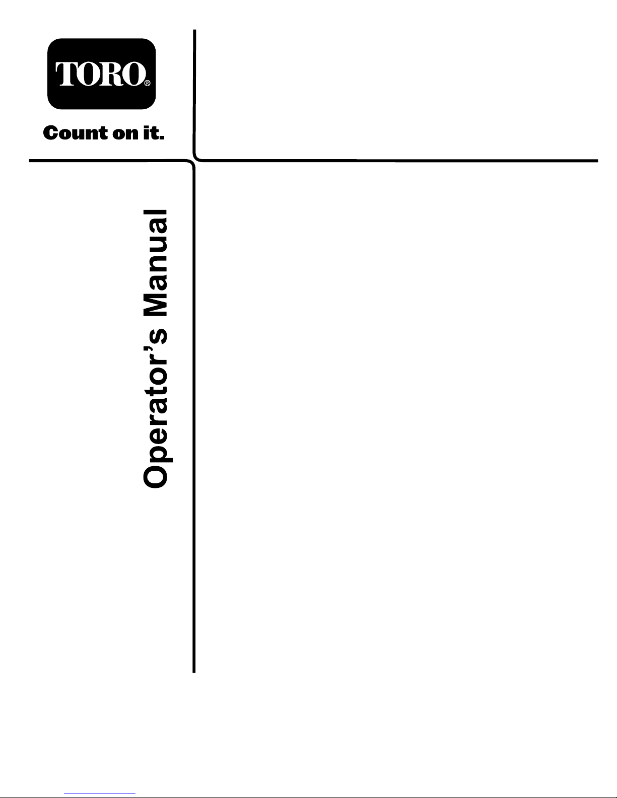
93-9084
1.Liftpoint
2.Tie-downpoint
106-6755
1.Enginecoolantunder
pressure.
3.Warning—donottouchthe
hotsurface.
2.Explosionhazard—read
theOperator'sManual.
4.Warning—readthe
Operator'sManual.
115-2047
1.Warning—donottouchthehotsurface.
115-7740
1.Warning—maximumtrailerweightis1500lb(680kg),
maximumtongueweightis200lb(90kg).
2.Warning—trailerbrakesarerequiredwhentowinggreater
than1500lb(680kg),maximumtrailerweightwithtrailer
brakesis3500lb(1591kg),maximumtongueweightwith
trailerbrakesis600lb(273kg).
115-7723
1.Warning—thehydraulicoilpressureis124bar(1800PSI).
2.CouplerA
3.CouplerB
93-9879
1.Storedenergyhazard—readtheOperator'sManual.
117–2718
8
Page 9
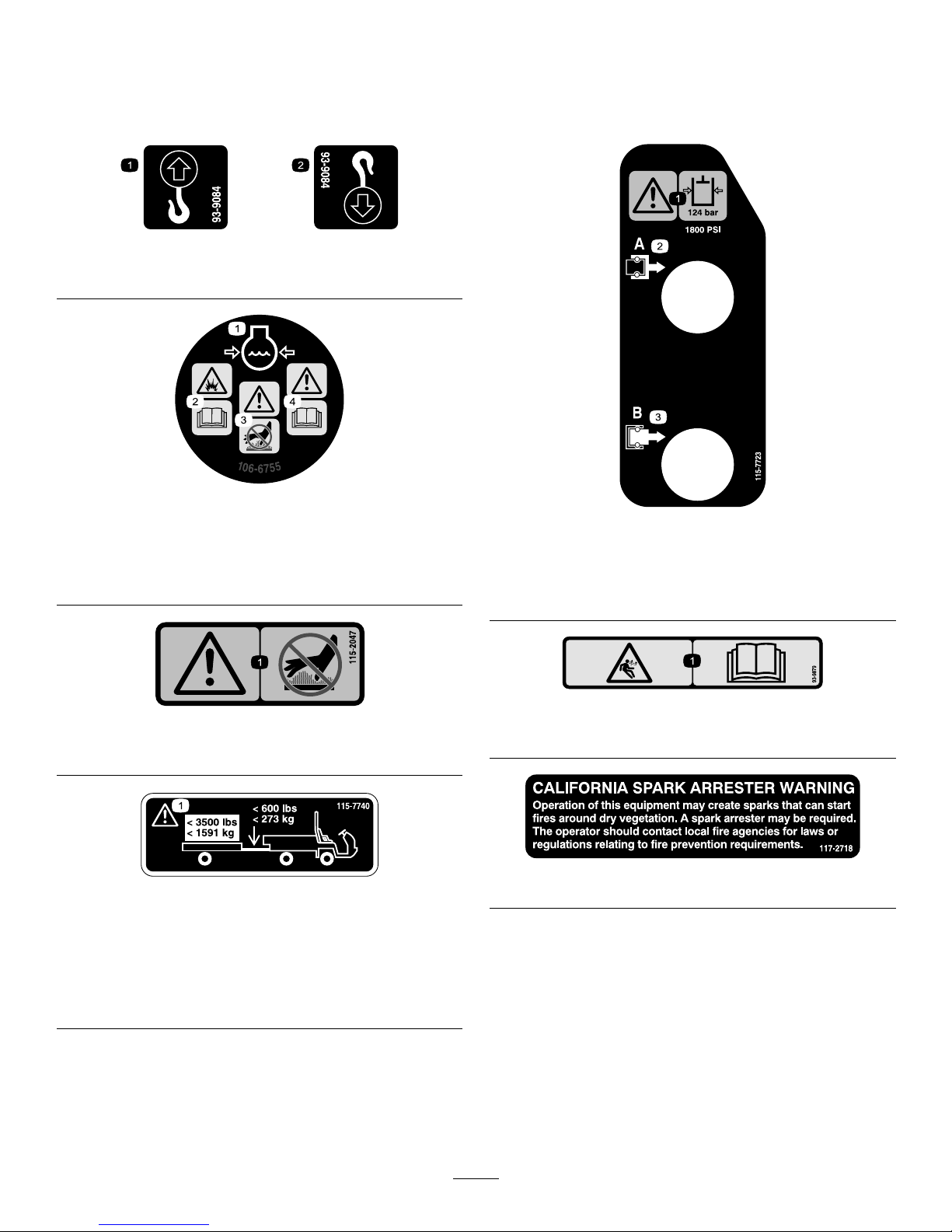
115-7746
1.Warning—donotoperatethismachineunlessyouaretrained.
3.Firehazard—stoptheenginebeforefueling.
2.Warning—locktheparkingbrake,stoptheengine,and
removetheignitionkeybeforeleavingthemachine.
4.Tippinghazard—slowdownandturngradually,usecaution
anddriveslowlywhendrivingonslopes,donotexceed20
mph(32kph),anddriveslowlyoverroughterrainorwhen
carryingafullorheavyload.
115-2282
1.Warning—readtheOperator'sManual.
2.Warning—stayawayfrommovingparts,keepallguardsandshieldsinplace.
3.Crushing/dismembermenthazardofbystanders—keepbystandersasafedistancefromthevehicle,donotcarrypassengersin
thecargobed,keeparmsandlegsinsideofthevehicleatalltimes,anduseseatbeltsandhandholds.
115-7741
1.ReadtheOperator’sManualbeforeservicingtransmission
uid.
93-7814
1.Entanglementhazard,belt—stayawayfrommovingparts.
105-4215
1.Warning—avoidpinchpoints.
106-2353
1.Electricalpowerpoint
9
Page 10
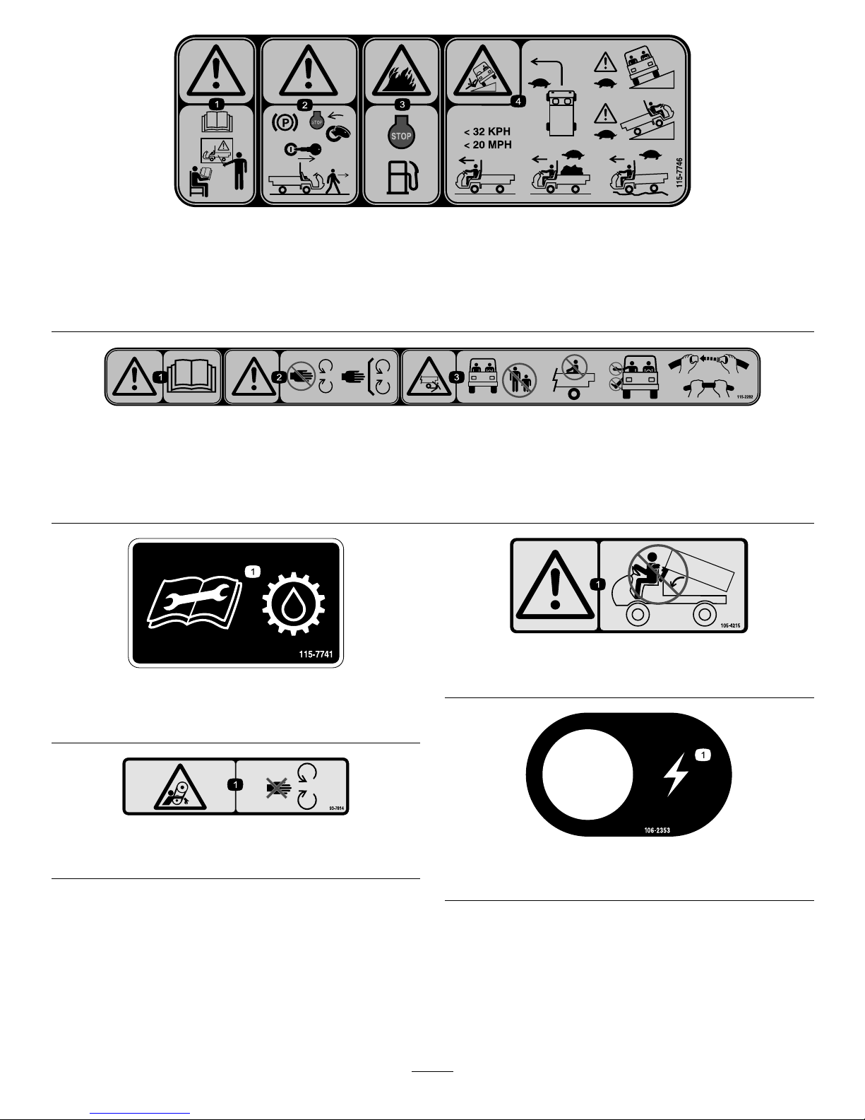
106-2355
1.Slow
3.Transmission—thirdhigh;
nofastspeed
2.Fast
115-7739
1.Falling,crushinghazard,bystanders—noriderson
machine.
93–9868
1.Crushinghazardofhand—readtheOperator’sManual.
BatterySymbols
Someorallofthesesymbolsareonyourbattery
1.Explosionhazard
6.Keepbystandersasafe
distancefromthebattery .
2.Nore,opename,or
smoking.
7.Weareyeprotection;
explosivegasescan
causeblindnessandother
injuries
3.Causticliquid/chemical
burnhazard
8.Batteryacidcancause
blindnessorsevereburns.
4.Weareyeprotection9.Flusheyesimmediately
withwaterandgetmedical
helpfast.
5.ReadtheOperator's
Manual.
10.Containslead;donot
discard.
115-7756
1.Highowhydraulics—engaged
115-7813
1.Poweroutlet10A5.Lights,brake15A
2.Switchedpower10A
6.Hazard10A
3.Fuelpump,supervisor
switch10A
7.4WD,Transmission10A
4.Horn,powerpoint15A
93-9850
1.Donotrepairorrevise—readtheOperator'sManual.
10
Page 11
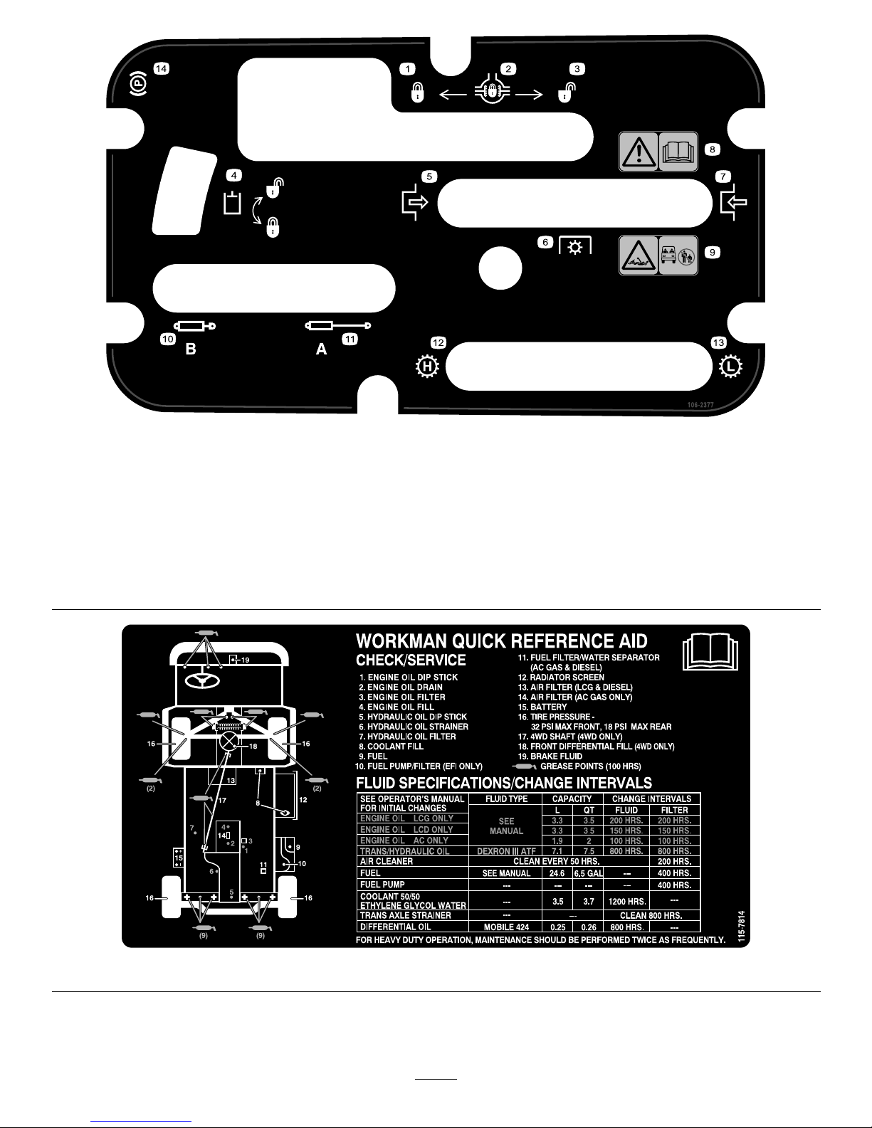
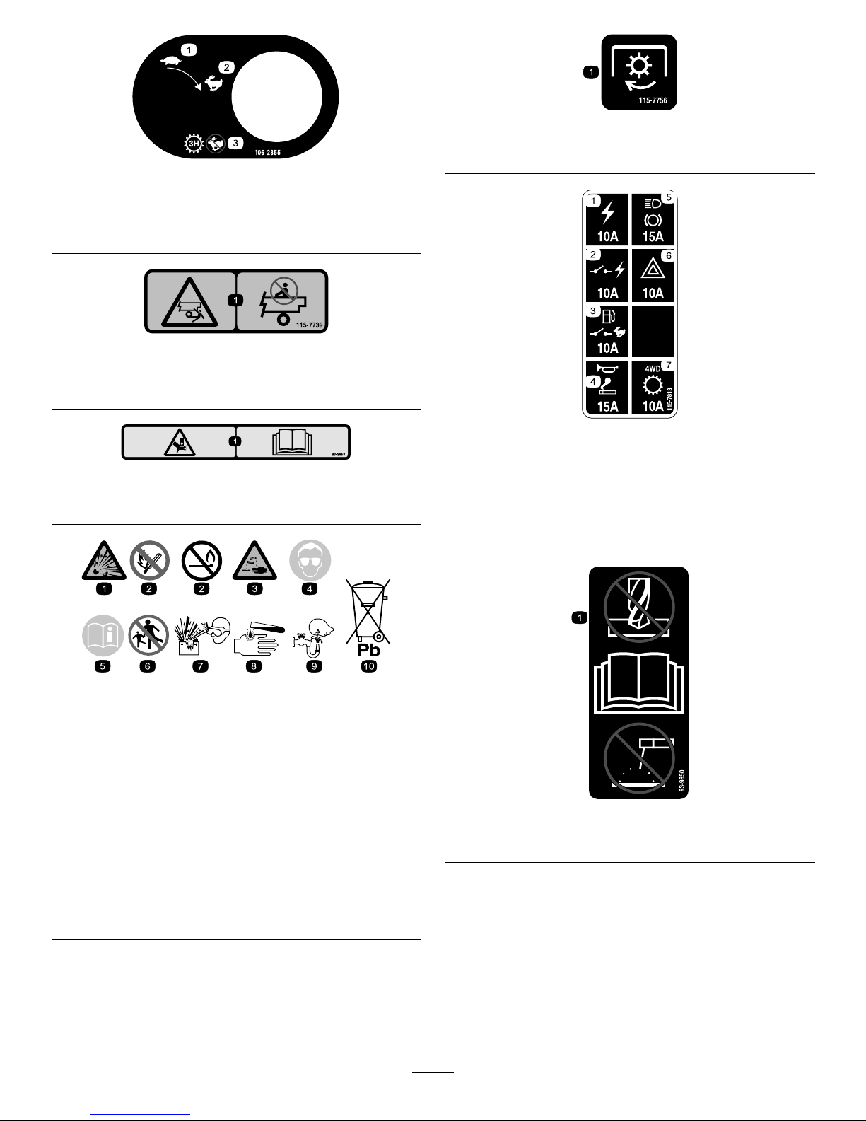
106-2377
1.Locked
8.Warning—readtheOperator'sManual.
2.Differentiallock9.Entanglementhazard,shaft—keepbystander'sasafe
distancefromthevehicle.
3.Unlocked10.Retracthydraulics
4.Hydrauliclock11.Extendhydraulics
5.Engage12.Transmission—highspeed
6.Powertake-off(PTO)
13.Transmission—lowspeed
7.Disengage14.Parkingbrake
115-7814
11
Page 12
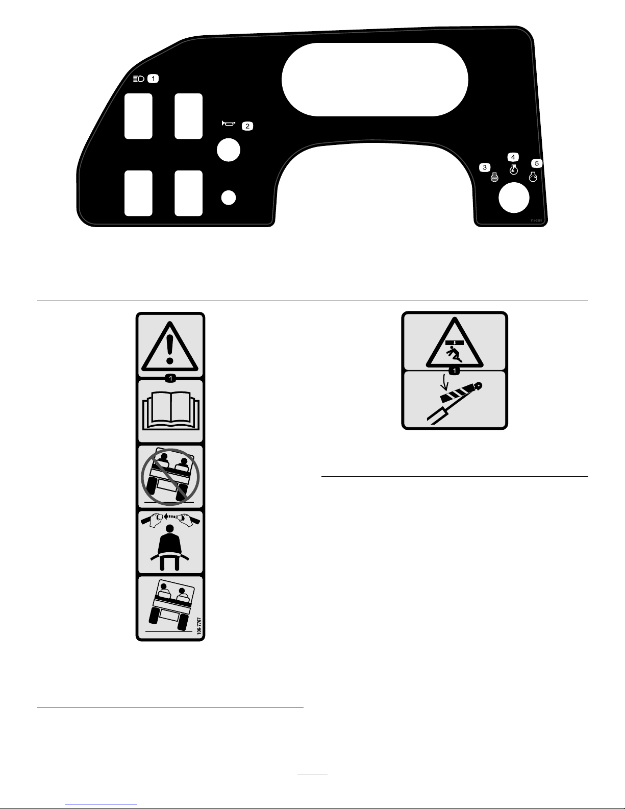
115-2281
1.Headlights4.Engine—run
2.Horn5.Engine—start
3.Engine—stop
106-7767
1.Warning—readtheOperator'sManual;avoidtippingthe
machine;weartheseatbelt;leanawayfromthedirection
themachineistipping.
93-9899
93-9899
1.Crushinghazard—installthecylinderlock.
12
Page 13
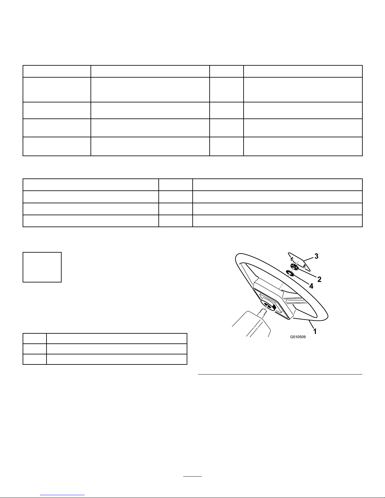
Setup
LooseParts
Usethechartbelowtoverifythatallpartshavebeenshipped.
ProcedureDescription
Qty.
Use
Steeringwheel
1
Cap
1
1
Washer1
Installthesteeringwheel.
ROPSframe
1
2
Bolt,1/2inch
6
MounttheROPS(RolloverProtection
System)
3
Electrolyte
A/R
Activateandchargethebattery.
4
Nopartsrequired
–
Checktheengineoil,transaxle/hydraulic
uid,andbrakeuidlevels
MediaandAdditionalParts
Description
Qty.
Use
Operator'sManual
1
Readbeforeoperatingthevehicle
PartsManual1
Usetoreferencepartnumbers
OperatorTrainingMaterial
1
Viewbeforeoperatingmachine
Note:Determinetheleftandrightsideofthemachinefromthenormaloperatingposition.
1
InstalltheSteeringWheel
(TCModelsOnly)
Partsneededforthisprocedure:
1
Steeringwheel
1
Cap
1Washer
Procedure
1.Removethenutfromthesteeringshaft.Slidethe
steeringwheelandwasherontothesteeringshaft
(
Figure3).
2.Securethesteeringwheeltotheshaftwiththenut
andtightenitto20-25ft-lb(27–34N-m).
3.Installthecaponthesteeringwheel.
Figure3
1.Steeringwheel3.Cap
2.Nut4.Washer
13
Page 14
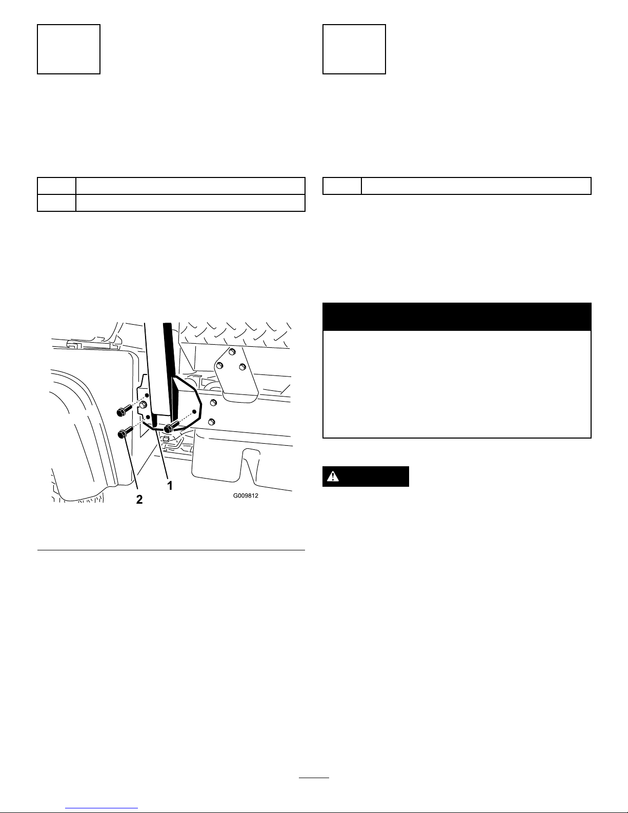
2
InstalltheROPS(Rollover
ProtectionSystem)
(TCModelsOnly)
Partsneededforthisprocedure:
1
ROPSframe
6
Bolt,1/2inch
Procedure
1.AligneachsideoftheROPSwiththemountingholes
oneachsideofvehicleframeasshownin
Figure4.
2.SecureeachsideoftheROPStoframewith3bolts
(1/2inch)andtightenthento85ft-lb(115N-m).
Figure4
1.ROPS
2.Mountingbracket
3
ActivateandChargethe
Battery
(TCModelsOnly)
Partsneededforthisprocedure:
A/R
Electrolyte
Procedure
Ifthebatteryisnotlledwithelectrolyteoractivated,it
mustberemovedfromthevehicle,lledwithelectrolyte
andcharged.Bulkelectrolytewith1.260specicgravity
canbepurchasedfromalocalbatterysupplyoutlet.
WARNING
CALIFORNIA
Proposition65Warning
Batteryposts,terminals,andrelated
accessoriescontainleadandleadcompounds,
chemicalsknowntotheStateofCalifornia
tocausecancerandreproductiveharm.
Washhandsafterhandling.
DANGER
Batteryelectrolytecontainssulfuricacidwhichisa
deadlypoisonandcausessevereburns.
•Donotdrinkelectrolyteandavoidcontactwith
skin,eyesorclothing.Wearsafetyglassesto
shieldyoureyesandrubberglovestoprotect
yourhands.
•Fillthebatterywherecleanwaterisalways
availableforushingtheskin.
1.Removethebatterycoverfromthebatterycase
(Figure5).
14
Page 15
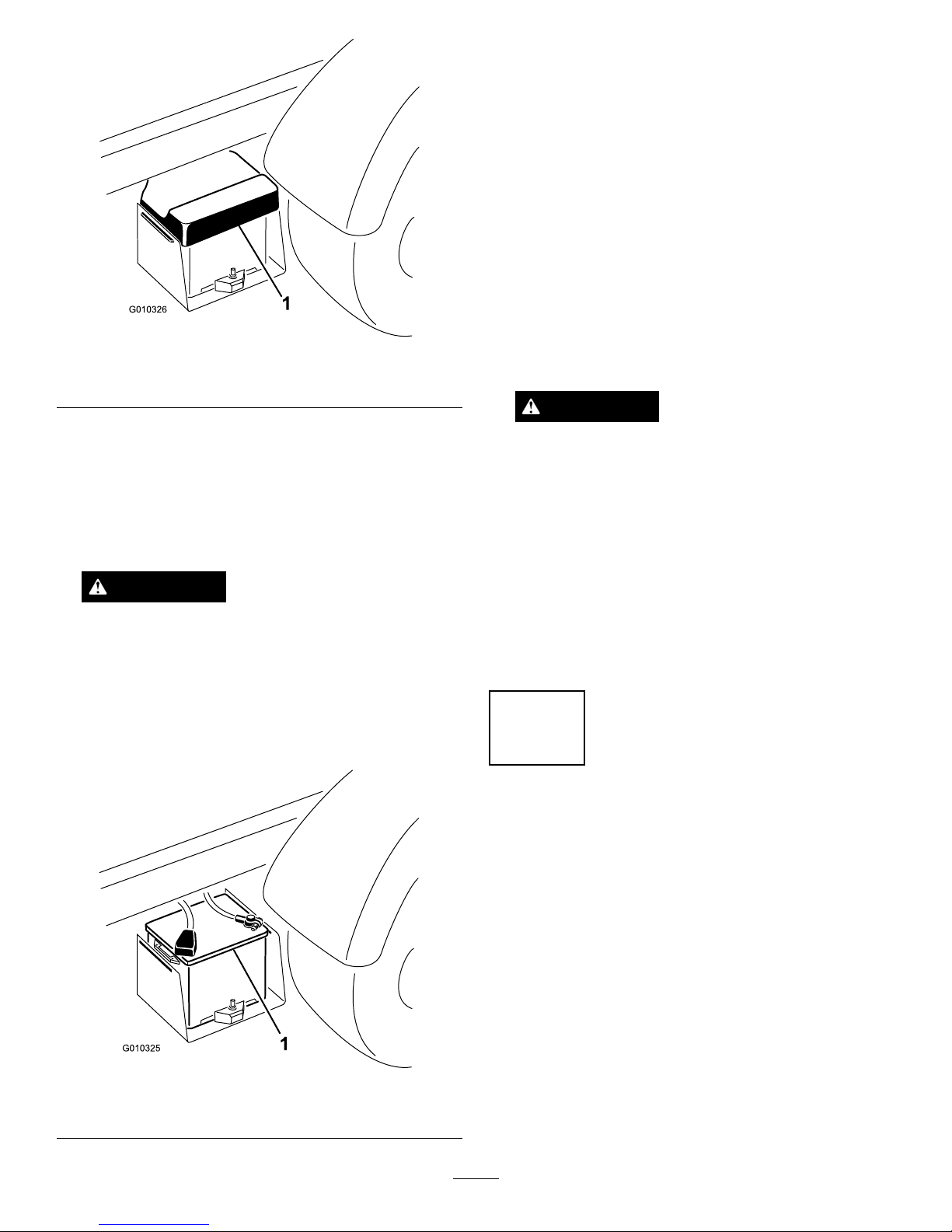
Figure5
1.Batterycover
2.Removethebatteryfromthebatterycase.
3.Removethellercapsfromthebatteryandslowly
lleachcelluntilelectrolyteisjustabovetheplates.
4.Replacethellercapsandconnecta3to4amp
batterychargertothebatteryposts.Chargethe
batteryatarateof3to4amperesfor4to8hours.
WARNING
Chargingthebatteryproducesgassesthatcan
explode.
Neversmokenearthebatteryandkeepsparks
andamesawayfrombattery.
5.Whenthebatteryischarged,disconnectthecharger
fromtheelectricaloutletandbatteryposts(Figure6).
Figure6
1.Battery
6.Removethellercaps.Slowlyaddelectrolytetoeach
celluntillevelisuptothellring.Installtheller
caps.
Important:Donotoverllthebattery.
Electrolytewilloverowontootherpartsofthe
vehicleandseverecorrosionanddeterioration
willresult.
7.Insertthebatteryintothebatterycasesothebattery
terminalsaretowardtheoutsideofthevehicle.
8.Installthepositivecable(red)tothepositive(+)
terminalandthenegativecable(black)tothe
negative(–)terminalofthebatteryandsecurethen
withboltsandnuts.Slidetherubberbootoverthe
positiveterminaltopreventapossibleshort-out
fromoccurring.
WARNING
Incorrectbatterycableroutingcoulddamage
themachineandcablescausingsparks.Sparks
cancausethebatterygassestoexplode,
resultinginpersonalinjury.
•Alwaysdisconnectthenegative(black)
batterycablebeforedisconnectingthe
positive(red)cable.
•Alwaysconnectthepositive(red)battery
cable
9.Installthebatterycoveronthebatterycase.
4
CheckingFluidLevels
NoPartsRequired
Procedure
1.Checktheengineoillevelbeforeandaftertheengine
isrststarted,refertoCheckingtheEngineOil
LevelinOperation.
2.Checkthetransaxle/hydraulicuidlevelbefore
theengineisrststarted,refertoCheckingthe
Transaxle/HydraulicFluidLevelinOperation.
3.Checkthebrakeuidlevelbeforetheengineisrst
started,refertoCheckingtheBrakeFluidLevelin
Operation.
15
Page 16
ProductOverview
Controls
Note:Determinetheleftandrightsidesofthemachine
fromthenormaloperatingposition.
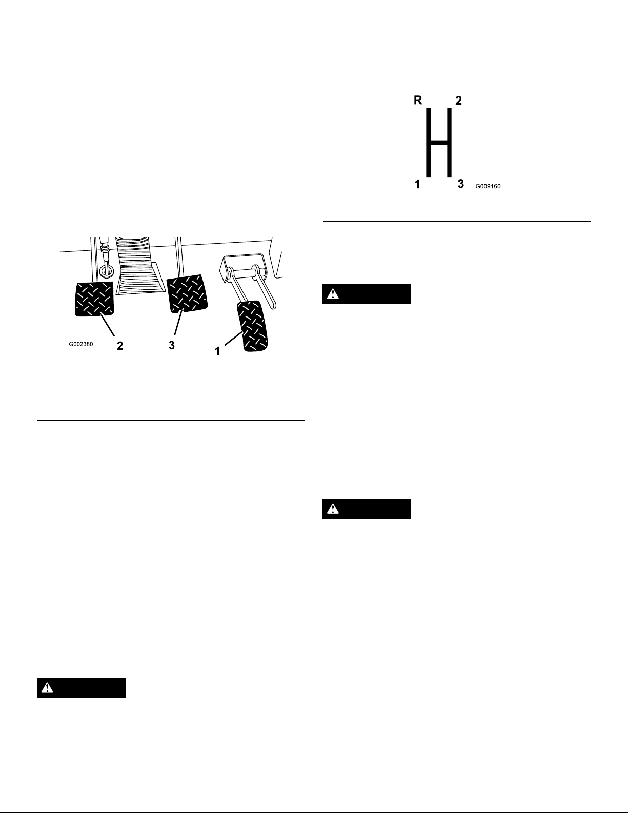
AcceleratorPedal
Theacceleratorpedal(Figure7)givestheoperator
theabilitytovarytheengineandgroundspeedofthe
vehicle,whenthetransmissionisingear.Pressing
thepedalincreasesengineRPMandgroundspeed.
ReleasingthepedalwilldecreaseengineRPMand
groundspeedofthemachine.
Figure7
1.Acceleratorpedal3.Brakepedal
2.Clutchpedal
ClutchPedal
Theclutchpedal(Figure7)mustbefullypressedto
disengageclutchwhenstartingtheengineorshifting
transmissiongears.Releasethepedalsmoothlywhenthe
transmissionisingeartopreventunnecessarywearon
thetransmissionandotherrelatedparts.
Important:Donotridetheclutchpedalduring
operation.Theclutchpedalmustbefullyoutorthe
clutchwillslipcausingheatandwear.Neverhold
thevehiclestoppedonahillusingtheclutchpedal.
Damagetotheclutchmayoccur.
BrakePedal
Thebrakepedal(Figure7)isusedtoapplyservice
brakestostoporslowvehicle.
CAUTION
Wornormaladjustedbrakesmayresultinpersonal
injury.Ifthebrakepedaltravelstowithin1-1/2
inches(3.8cm)ofthevehicleoorboard,thebrakes
mustbeadjustedorrepaired.
GearShiftLever
Fullypresstheclutchpedalandmovetheshiftlever
(Figure7)intothedesiredgearselection.Adiagramof
theshiftpatternisindicatedinFigure8.
Figure8
Important:Donotshiftthetransaxletothereverse
orforwardgearunlessthevehicleisstandingstill.
Damagetothetransaxlemayoccur.
CAUTION
Downshiftingfromtoohighaspeedcancause
therearwheelstoskidresultinginlossofvehicle
controlaswellasclutchand/ortransmission
damage.Shiftsmoothlytoavoidgrindinggears.
DifferentialLock
Thedifferentiallockallowsrearaxletobelockedfor
increasedtraction.Thedifferentiallock(
Figure9)may
beengagedwhenthevehicleisinmotion.Movethe
leverforwardandtotherighttoengagethelock.
Note:Vehiclemotionplusaslightturnisrequiredto
engageordisengagedifferentiallock.
CAUTION
Turningwiththedifferentiallockoncanresult
inlossofvehiclecontrol.Donotoperatewith
differentiallockonwhenmakingsharpturnsorat
highspeeds.Refertousingthedifferentiallock.
16
Page 17
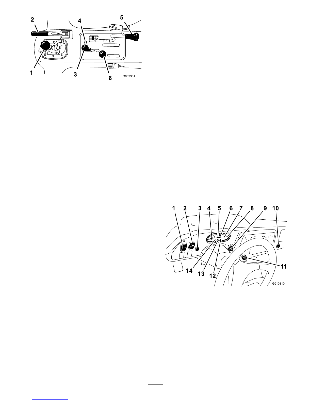
Figure9
1.Gearshiftlever4.Hydraulicliftlock
2.Parkingbrake
5.Differentiallock
3.Hydraulicbedlift6.High–lowrangeshifter
ParkingBrake
Whenevertheengineisshutoff,theparkingbrake
(Figure9)mustbeengagedtopreventaccidental
movementofthevehicle.Toengagetheparkingbrake,
pullbackonthelever.Todisengage,pushthelever
forward.Releasetheparkingbrakebeforemovingthe
vehicle.Ifyouparkthevehicleonasteepgrade,apply
theparking.Also,shiftthetransmissioninto1stgear
onauphillgradeorreverseonadownhillgrade.Place
chocksatthedownhillsideofthewheels.
HydraulicLift
Thehydraulicliftraisesandlowersbed.Moveitrearward
toraisethebed,andforwardtolowerit(Figure9).
Important:Whenloweringthebed,holdthelever
intheforwardpositionfor1or2secondsafterthe
bedcontactstheframetosecureitinthelowered
position.Donotholdthehydraulicliftineitherthe
raiseorlowerposition,formorethan5seconds,
oncethecylindershavereachedtheendoftheir
travel.
HydraulicLiftLock
Thehydraulicliftlocklockstheliftleversothehydraulic
cylindersdonotoperatewhenthevehicleisnot
equippedwithabed(
Figure9).Italsolocksthelift
leverintheOnpositionwhenusingthehydraulicsfor
attachments.
High–LowRangeShifter
Thehigh–lowrangeshifteraddsthreeadditionalspeeds
forprecisespeedcontrol(Figure9).
•Thevehiclemustbecompletelystoppedbefore
shiftingbetweenHighandLowrange.
•Shiftonlyonlevelground.
•Pressclutchpedalfully.
•MovetheleverfullyforwardforHighandfully
rearwardforLow.
Highisforhigherspeeddrivingonlevel,drysurfaces
withlightloads.
Lowisforlowspeeddriving.Usethisrangewhen
greaterthannormalpowerorcontrolisrequired.For
example,steepgrades,difcultterrain,heavyloads,slow
speedbuthighenginespeed(spraying).
Important:ThereisalocationbetweenHighand
Lowinwhichthetransaxleisinneitherrange.
Donotusethispositionasaneutralposition
becausethevehiclecouldmoveunexpectedlyifthe
High–Lowshifterisbumpedandthegearshift
leverisingear.
IgnitionSwitch
Usetheignitionswitch(Figure10)tostartandstop
theengine.Ithasthreepositions:Off,Run,andStart.
RotatethekeyclockwisetotheStartpositiontoengage
thestartermotor.Releasethekeywhentheenginestarts.
ThekeywillmoveautomaticallytotheOnposition.To
shuttheengineoff,rotatethekeycounterclockwiseto
theOffposition.
Figure10
1.Lightswitch8.Fuelgauge
2.Highow
hydraulicsswitch
(TCmodelsonly)
9.Ignitionswitch
3.Horn
(TCmodelsonly)
10.Powerpoint
4.Tachometer11.3rdhighlockoutswitch
5.Speedometer12.Oilpressurewarninglight
6.Hourmeter
13.Checkenginelight
7.Coolanttemperature
gaugeandlight
14.Chargeindicator
17
Page 18

HourMeter
Indicatesthetotalhoursofmachineoperation.The
hourmeter(Figure10)startstofunctionwheneverthe
keyswitchisrotatedtotheOnpositionoriftheengine
isrunning.
3rdHighLockoutSwitch
Movethe3rdhighlockoutswitch(Figure10)totheslow
positionandremovethekeytopreventtheuseofthird
gearwhenintheHighrange.Theenginewillshutoff
iftheshiftleverismovedtothirdgearwheninHigh
range.Thekeyisremovableineitherposition.
LightSwitch
Pushthelightswitch(Figure10)totoggletheheadlights
onoroff.
OilPressureWarningLight
Theoilpressurewarninglightglows(Figure10)ifthe
engineoilpressuredropsbelowasafelevelwhilethe
engineisrunning.Ifthelightickersorremainson,
stopthevehicle,turnofftheengine,andchecktheoil
level.Iftheoillevelwaslow,butaddingoildoesnot
causethelighttogooutwhentheengineisrestarted,
turntheengineoffimmediatelyandcontactyourlocal
Torodistributorforassistance.
Checktheoperationofwarninglightsasfollows:
1.Applytheparkingbrake.
2.TurntheignitionkeytotheOnposition,butdonot
starttheengine.Theoilpressurelightshouldglow
red.Ifthelightdoesnotfunction,eitherabulbis
burnedoutorthereisamalfunctioninthesystem
whichmustberepaired.
Note:Ifenginewasjustturnedoff,itmaytake1to2
minutesforthelighttocomeon.
CoolantTemperatureGaugeandLight
Registersthecoolanttemperatureintheengine.
OperatesonlywhentheignitionswitchisinOnposition
(Figure10).Theindicatorlightwillilluminateblinking
rediftheengineoverheats.
ChargeIndicator
Illuminateswhenbatteryisbeingdischarged.Iflight
illuminatesduringoperation,stopvehicle,turnoff
engineandcheckforpossiblecauses,suchasalternator
belt(Figure10).
Important:Ifalternatorbeltislooseorbroken,do
notoperatethevehicleuntiladjustmentorrepairis
complete.Failuretoobservethisprecautionmay
resultindamagetotheengine.
Checktheoperationofwarninglightsasfollows:
•Applyparkingbrake.
•TurntheignitionkeytotheOnposition,butdonot
starttheengine.Thecoolanttemperature,charge
indicator,andoilpressurelightsshouldglow .Ifany
lightdoesnotfunction,eitherabulbisburnedout
orthereisamalfunctioninthesystemwhichmust
berepaired.
FuelGauge
Thefuelgaugeshowstheamountoffuelinthetank.It
operatesonlywhenignitionswitchisintheOnposition
(
Figure10).Redindicateslowfuellevelandblinking
redindicatesnearempty .
HighFlowHydraulicsSwitch(TC
modelsonly)
Turnontheswitchtoactivatethehighowhydraulics
(Figure10).
HornButton(TCmodelsonly)
Pressingthehornbuttonactivatesthehorn(Figure10).
Tachometer
RegisterstheRPMoftheengine(Figure10&Figure11).
WhitetriangleindicatesdesiredRPMforPTOoperation
(
Figure11).
Figure11
1.RPMoftheengine2.3300RPMfor540RPM
PTOoperation
18
Page 19
CheckEngineLight
Thelight(Figure10)willilluminatetonotifyoperatorof
aenginemalfunction.
Important:Theengineisequippedwithonboard
diagnosticstotroubleshootenginemalfunctions.
RefertotheToroServiceManualforinformation
ontheoperationofthediagnosticsandhowtoread
thecodesofthesystem.
Speedometer
Registersthegroundspeedofthevehicle(Figure10).
ThespeedometerisinMPHbutcaneasilyconvertedto
KPH.RefertoConvertingtheSpeedometerinControls
Maintenance.
PowerPoint
Usethepowerpoint(Figure10)topoweroptional12
voltelectricalaccessories.
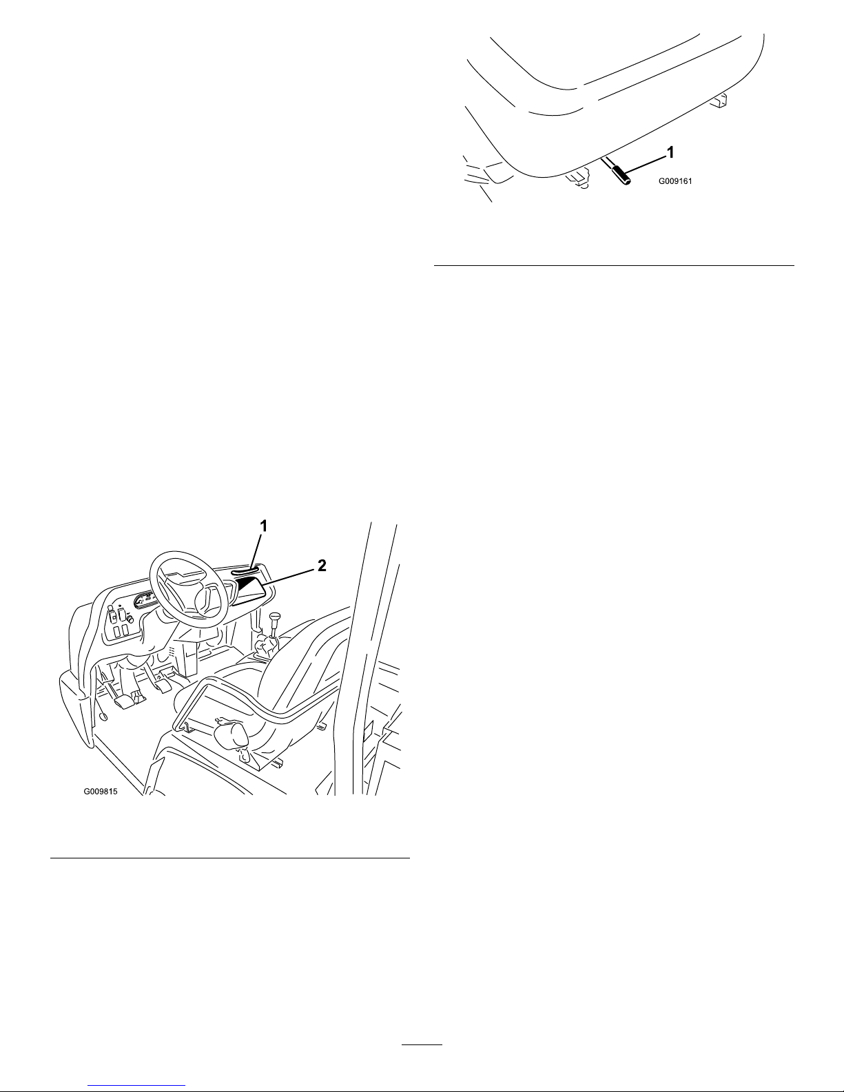
PassengerHandHold
Thepassengerhandholdislocatedonthedashboard
(Figure12).
Figure12
1.Passengerhandhold
2.Storagecompartment
SeatAdjustingLever
Theseatscanbeadjustedforeandaftforoperator
comfort(Figure13).
Figure13
1.Seatadjustinglever
19
Page 20
Specications
Note:Specicationsanddesignaresubjecttochange
withoutnotice.
Dimensions
OverallWidth63inches(160cm)
OverallLength
w/obed:128.25inches(326cm)
w/fullbed:130.38inches(331cm)
w/2/3bedinrearmountinglocation:
136.38inches(346cm)
BaseWeight(Dry)
Model07366—1623lb(736kg)
Model07367—1951lb(885kg)
Model07367TC—2032lb(921.6kg)
Model07370—2010lb(912kg)
Model07370TC—2091lb(948kg)
RatedCapacity
(includes200lb.
operator,200lb.
passengerandloaded
attachment).
Model07366—3227lb(1464kg)
Model07367—2899lb(1315kg)
Model07367TC—2818lb(1278kg)
Model07370—2840lb(1288kg)
Model07370TC—2759lb(1251kg)
Maximum.Gross
VehicleWeight
4,850lb(2200kg)
TowCapacityT ongueweight600lb(272kg)
Maximumtrailerweight3,500lb(1587
kg)
GroundClearance7inches(18cm)w/noload
WheelBase
70inches(1 18cm)
WheelTread(center
linetocenterline)
Front:46inches(117cm)
Rear:47.7inches(121cm)
Height
75inches(190.5cm)totopofROPS
Attachments/Accessories
AselectionofToroapprovedattachmentsand
accessoriesareavailableforusewiththemachineto
enhanceandexpanditscapabilities.Contactyour
AuthorizedServiceDealerorDistributororgoto
www.Toro.comforalistofallapprovedattachments
andaccessories.
Operation
Note:Determinetheleftandrightsidesofthe
machinefromthenormaloperatingposition.
CAUTION
Beforeservicingormakingadjustmentstothe
machine,stoptheengine,settheparkingbrake,
andremovethekeyfromtheswitch.Removeany
loadmaterialfromthebedorotherattachment
beforeworkingunderaraisedbed.Neverwork
underaraisedbedwithoutpositioningthesafety
supportonafullyextendedcylinderrod.
CheckingtheEngineOilLevel
ServiceInterval:Beforeeachuseordaily
Theengineisshippedwithapproximately3.5quarts
(3.3l)(w/lter)ofoilinthecrankcase;however,you
shouldchecktheoillevelbeforeandaftertheengine
isrststarted.
Note:Thebesttimetochecktheengineoiliswhen
theengineiscoolbeforeithasbeenstartedforthe
day.Ifithasalreadybeenrun,allowtheoiltodrain
backdowntothesumpforatleast10minutesbefore
checking.IftheoillevelisatorbelowtheAddmark
onthedipstick,addoiltobringtheoilleveltotheFull
mark.Donotoverll.Iftheoillevelisbetweenthe
FullandAddmarks,noadditionaloilisrequired.
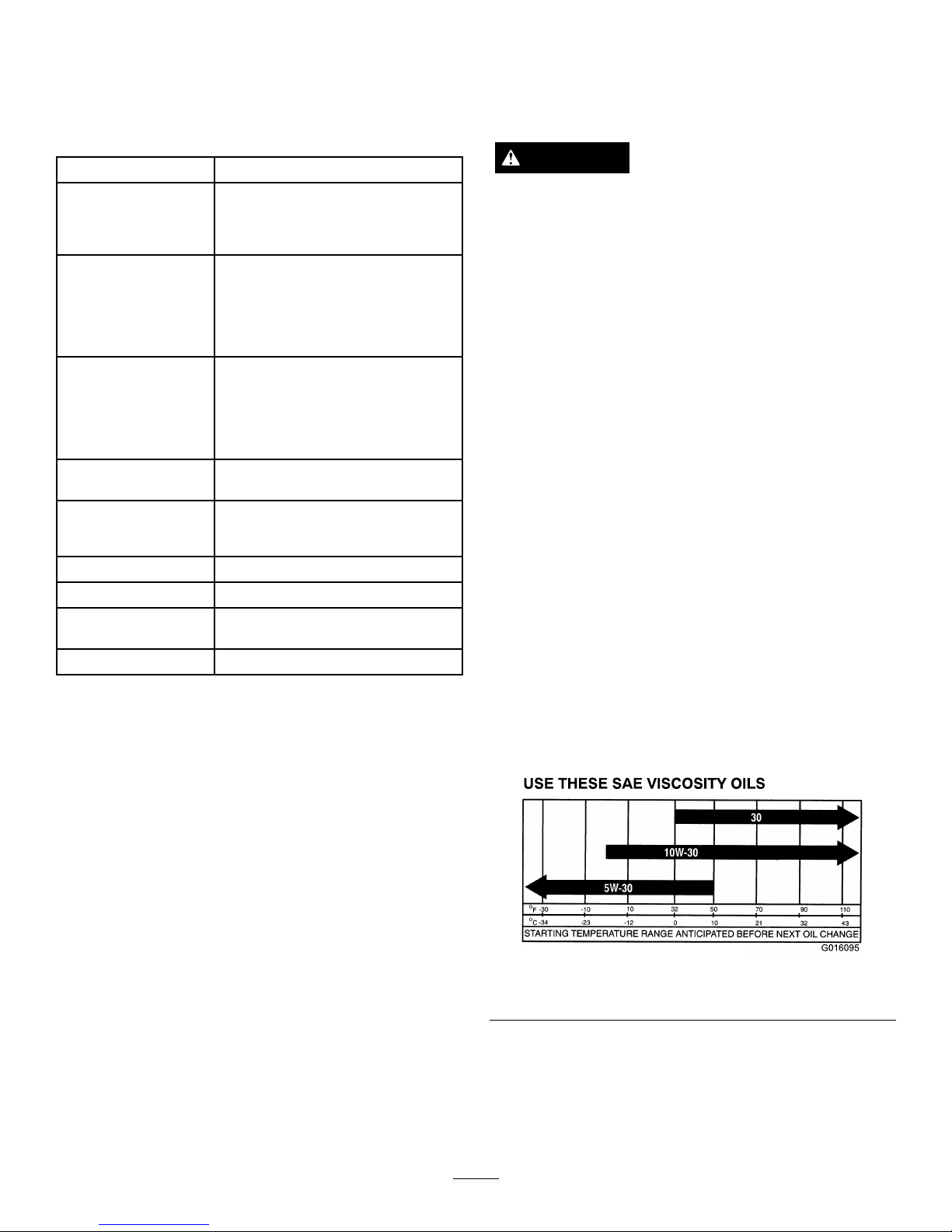
Theengineusesanyhigh-quality10W-30detergentoil
havingtheAmericanPetroleumInstitute(API)service
classicationSJ,SK,SL,SM,orhigher.Choosea
viscosityaccordingtothetablein
Figure14.
G016095
Figure14
1.Positionthemachineonalevelsurface.
2.Removethedipstick(Figure15)andwipeitwitha
cleanrag.Insertthedipstickintothetubeandmake
sureitisseatedfully.Removedipstickandcheck
theleveloftheoil.
20
Page 21

Figure15
1.Fillercap
2.Dipstick
3.Iftheoillevelislow ,removethellercap(Figure15)
andaddenoughoiltoraisetheleveltotheFull
markonthedipstick.
Note:Whenaddingoil,removedipsticktoallow
properventing.Pouroilslowlyandcheckthelevel
oftenduringthisprocess.Donotoverll.
Important:Whenaddingengineoilorlling
oil,theremustbeclearancebetweentheoilll
deviceandtheoilllholeinthevalvecoveras
shownin
Figure16.Thisclearanceisnecessary
topermitventingwhenlling,whichprevents
oilfromoverrunningintothebreather.
Figure16
1.Noteclearance
4.Installthedipstickrmlyinplace.
AddingFuel
TheT oro®Companystronglyrecommendsthe
useoffresh,clean,unleadedregulargradegasoline
inT orogasolinepoweredproducts.Unleaded
gasolineburnscleaner,extendsenginelife,and
promotesgoodstartingbyreducingthebuild–up
ofcombustionchamberdeposits.Useaminimum
octaneratingof87.
Fueltankcapacity:6.5USgallons(25l).
Note:Neverusemethanol,leadedgasoline,
gasolinecontainingmethanol,gasolinecontaining
morethan10%ethanol,gasolineadditives,orwhite
gasbecauseenginefuelsystemdamagecould
result.
21
Page 22

DANGER
Incertainconditions,gasolineisextremely
ammableandhighlyexplosive.Areorexplosion
fromgasolinecanburnyouandothersandcan
damageproperty.
•Beforeremovingthefueltankcap,makesure
thevehicleispositionedonalevelsurface.
Openfueltankcapslowly.
•Fillthefueltankoutdoors,inanopenarea,
whentheengineiscold.Wipeupanygasoline
thatspills.
•Neverllthefueltankinsideanenclosedtrailer.
•Donotllthefueltankcompletelyfull.Add
gasolinetothefueltankuntilthelevelis1inch
(25mm)belowthebottomofthellerneck.
Thisemptyspaceinthetankallowsgasoline
toexpand.
•Neversmokewhenhandlinggasoline,andstay
awayfromanopenameorwheregasoline
fumesmaybeignitedbyaspark.
•Storegasolineinanapprovedcontainerand
keepitoutofthereachofchildren.Neverbuy
morethana30-daysupplyofgasoline.
•Donotoperatewithoutentireexhaustsystem
inplaceandinproperworkingcondition.
DANGER
Incertainconditionsduringfueling,static
electricitycanbereleasedcausingasparkwhich
canignitethegasolinevapors.Areorexplosion
fromgasolinecanburnyouandothersandcan
damageproperty.
•Alwaysplacegasolinecontainersontheground
awayfromyourvehiclebeforelling.
•Donotllgasolinecontainersinsideavehicle
oronatruckortrailerbedbecauseinterior
carpetsorplastictruckbedlinersmayinsulate
thecontainerandslowthelossofanystatic
charge.
•Whenpractical,removegas-powered
equipmentfromthetruckortrailerandrefuel
theequipmentwithitswheelsontheground.
•Ifthisisnotpossible,thenrefuelsuch
equipmentonatruckortrailerfromaportable
container,ratherthanfromagasolinedispenser
nozzle.
•Ifagasolinedispensernozzlemustbeused,
keepthenozzleincontactwiththerimofthe
fueltankorcontaineropeningatalltimesuntil
fuelingiscomplete.
1.Cleantheareaaroundthefueltankcap.
2.Removethefueltankcap(Figure17).
Figure17
1.Fueltankcap
3.Fillthetanktoaboutoneinchbelowthetopofthe
tank,(bottomofthellerneck),theninstallthecap.
Donotoverll.
4.Wipeupanyfuelthatmayhavespilledtopreventa
rehazard.
22
Page 23

CheckingtheCoolingSystem
ServiceInterval:Beforeeachuseordaily
Coolingsystemcapacity:4qt(3.7l)
Thecoolingsystemislledwitha50/50solutionof
waterandpermanentethyleneglycolantifreeze.
1.Parkthemachineonalevelsurface.
CAUTION
Iftheenginehasbeenrunning,thepressurized,
hotcoolantcanescapeandcauseburns.
•Donotopentheradiatorcapwhenthe
engineisrunning.
•Allowtheenginetocoolatleast15minutes
oruntiltheradiatorcapiscoolenoughto
touchwithoutburningyourhand.
•Usearagwhenopeningtheradiatorcap,
andopenthecapslowlytoallowsteamto
escape.
2.Checkthecoolantlevelonthesideofthereserve
tank(Figure18).Thecoolantshouldbeuptothe
Coldline,whenengineiscold.
Figure18
1.Reservetank
3.Coldline
2.Hotline
3.Ifcoolantislow ,removethereservetankcap
andadda50/50mixtureofwaterandpermanent
ethyleneglycolantifreeze.Donotoverll.
4.Installthereservetankcap.
Checkingthe
Transaxle/HydraulicFluid
Level
ServiceInterval:Beforeeachuseordaily
ThetransaxlereservoirislledwithDexronIIIATF.
Checkthelevelbeforetheengineisrststartedand
every8hoursordaily,thereafter.Capacityofsystemis.
Transaxlereservoircapacity:7.5qt(7l).
1.Positionthevehicleonalevelsurface.
2.Cleantheareaaroundthedipstick(
Figure19).
Figure19
1.Dipstick
3.Unscrewthedipstickfromthetopofthetransaxle
andwipeitwithacleanrag.
4.Screwthedipstickintothetransaxleandensurethat
itisfullyseated.
5.Unscrewthedipstickandchecktheuidlevel.
Theuidshouldbeuptotopoftheatportion
ofthedipstick.
6.Ifthelevelislow ,addenoughuidtoachievethe
properlevel.
CheckingtheHighFlow
HydraulicFluid(TCmodels
only)
ServiceInterval:Beforeeachuseordaily
Thehighowhydraulicsreservoirislledwith
approximately4USgallons(15l)ofhighquality
hydraulicuid.Checkthelevelofhydraulic
uidbeforetheengineisrststartedanddaily
thereafter.
1.Cleantheareaaroundthellerneckandthecap
ofthehydraulictank(
Figure20).Removethecap
fromthellerneck.
23
Page 24

Figure20
1.Cap
2.Removethedipstick(Figure20)fromthellerneck
andwipeitwithacleanrag.Insertthedipstickinto
thellerneck;thenremoveitandchecktheuid
level.Theuidlevelshouldbebetweenthetwo
marksonthedipstick.
3.Ifthelevelislow ,addtheappropriateuidtoraise
theleveltotheuppermark.RefertoChangingthe
HighFlowHydraulicFluid.
4.Installthedipstickandcapontothellerneck.
5.Starttheengineandturnontheattachment.Let
themrunforabouttwominutestopurgeairfrom
thesystem.Stoptheengineandattachmentand
checkforleaks.
Important:Thevehiclemustberunning
beforestartingthehighowhydraulics.
WARNING
Hydraulicuidescapingunderpressurecan
penetrateskinandcauseinjury.
•Makesureallhydraulicuidhosesand
linesareingoodconditionandallhydraulic
connectionsandttingsaretightbefore
applyingpressuretothehydraulicsystem.
•Keepyourbodyandhandsawayfrompin
holeleaksornozzlesthatejecthighpressure
hydraulicuid.
•Usecardboardorpapertondhydraulic
leaks.
•Safelyrelieveallpressureinthehydraulic
systembeforeperforminganyworkonthe
hydraulicsystem.
•Seekimmediatemedicalattentionifuidis
injectedintoyourskin.
CheckingtheFrontDifferential
OilLevel(FourWheelDrive
ModelsOnly)
ServiceInterval:Every100hours/Monthly(whichever
comesrst)
ThedifferentialislledwithMobil424hydraulicoil.
1.Positionthevehicleonalevelsurface.
2.Cleantheareaaroundthell/checkplugonsideof
thedifferential(
Figure21).
Figure21
1.Fill/checkplug
2.Drainplug
3.Removethell/checkplugandcheckthelevelof
theoil.Theoilshouldbeuptohole.Iftheoilis
low,addMobil424hydraulicoil.
4.Installthell/checkplug.
CheckingtheTorqueofthe
WheelNuts
ServiceInterval:Aftertherst2hours
Aftertherst10hours
Every200hours
WARNING
Failuretomaintainpropertorqueofthewheelnuts
couldresultinfailureorlossofawheelandmay
resultinpersonalinjury.
Torquethefrontandrearwheelnutsto80to90
ft-lb(109to122N-m)after1to4hoursofoperation
andagainafter10hoursofoperation.Torqueevery
200hoursthereafter.
24
Page 25

CheckingtheTirePressure
ServiceInterval:Beforeeachuseordaily
Themaximumairpressureinthefronttiresis32psi
(220kPa)andthereartiresis18psi(124kPa).
Checkthetirepressurefrequentlytoensureproper
ination.Ifthetiresarenotinatedtothecorrect
pressure,thetireswillwearprematurely.
Figure22isanexampleoftirewearcausedbyunder
ination.
Figure22
1.Underinatedtire
Figure23isanexampleoftirewearcausedbyover
ination.
Figure23
1.Overinatedtire
CheckingtheBrakeFluid
ServiceInterval:Beforeeachuseordaily—Checkthe
brakeuidlevel.
Every1,000hours/Every2years
(whichevercomesrst)—Change
thebrakeuid.
Thebrakeuidreservoirisshippedfromthefactory
lledwithDOT3brakeuid.Checkthelevelbefore
theengineisrststartedandevery8hoursordaily,
thereafter.
Thebrakeuidreservoirislocatedunderthedash.
1.Parkthemachineonalevelsurface.
2.TheuidlevelshouldbeuptotheFulllineonthe
reservoir(Figure24).
Figure24
1.Brakeuidreservoir
3.Iftheuidlevelislow,cleantheareaaroundthe
cap,removethereservoircap,andllthereservoir
totheproperlevel.Donotoverll.
Note:Youcanremovethehoodaccesstothereservoir
fromthefrontofthemachine(Figure25).
Figure25
1.Brakeuidreservoir
Pre–startingChecks
Safeoperationbeginsbeforetakingthevehicleoutfor
aday’swork.Youshouldchecktheseitemseachtime:
•Checkthetirepressure.
25
Page 26

Note:Thesetiresaredifferentthancartires,they
requirelesspressuretominimizeturfcompaction
anddamage.
•Checkalluidlevelsandaddtheappropriate
amountofTorospecieduids,ifanyarefound
tobelow .
•Checkthefrontoftheradiator.Removeanydebris
andcleantheradiatorscreen.
•Checkthebrakepedaloperation.
•Checktoseethatthelightsareworking.
•Turnthesteeringwheeltotheleftandrightto
checkthesteeringresponse.
•Stoptheengineandwitformovingpartstostop,
thencheckforoilleaks,looseparts,andanyother
noticeablemalfunctions.
Ifanyoftheaboveitemsarenotcorrect,notifyyour
mechanicorcheckwithyoursupervisorbeforetaking
thevehicleoutfortheday .Yoursupervisormaywant
youtocheckotheritemsonadailybasis,soaskwhat
yourresponsibilitiesare.
StartingtheEngine
1.Sitontheoperator’sseatandengagetheparking
brake.
2.DisengagethePTOandhighowhydraulics(ifso
equipped)andmovethehandthrottlelevertothe
Offposition(ifsoequipped).
3.MovetheshiftlevertotheNeutralpositionand
presstheclutchpedal.
4.Ensurethatthehydraulicliftleverisinthecenter
position.
5.Keepyourfootoffoftheacceleratorpedal.
Note:Iftheengineisooded—fullypressthe
acceleratorpedalandholdittotheooruntilthe
enginestarts.Neverpumptheacceleratorpedal.
6.Insertkeyintoignitionswitchandrotateitclockwise
tostarttheengine.Releasekeywhenenginestarts.
Important:Topreventoverheatingofthe
startermotor,donotengagestarterlongerthan
15seconds.After15secondsofcontinuous
cranking,wait60secondsbeforeengaging
startermotoragain.
DrivingtheVehicle
1.Releasetheparkingbrake.
2.Fullypresstheclutchpedal.
3.Movethegearshiftleverto1stgear.
4.Releasetheclutchpedalsmoothlywhilepressing
theacceleratorpedal.
5.Whenthevehiclegainsenoughspeed,removeyour
footfromtheacceleratorpedal,fullypressthe
clutchpedal,movethegearshiftlevertothenext
gearandreleasetheclutchpedalwhilepressingthe
acceleratorpedal.Repeattheprocedureuntilthe
desiredspeedisattained.
Important:Alwaysstopthevehiclebefore
shiftingtoreverseaforwardgearortoaforward
gearfromreverse.
Note:Avoidlongperiodsofengineidling.
Usethechartbelowtodeterminethegroundspeed
ofthevehicleat3600RPM.
Gear
RangeRatio
Speed
(mph)
Speed
(kmh)
1L82.83:12.94.7
2L54.52:14.57.2
3L31.56:1
7.7
12.5
1H32.31:17.612.2
2H21.27:111.518.5
3H12.31:119.831.9
RL86.94:12.84.5
RH33.91:17.111.6
Note:LeavingignitionswitchintheOnposition
forlongperiodsoftimewithoutrunningtheengine
willdischargethebattery.
Important:Donotattempttopushortow
vehicletogetitstarted.Damagetothedrive
traincouldresult.
StoppingtheVehicle
Tostopthevehicle,removeyourfootfromthe
acceleratorpedal,presstheclutchpedal,thenpressthe
brakepedal.
StoppingtheEngine
Tostoptheengine,rotatetheignitionkeytotheOff
positionandengagetheparkingbrake.Removethekey
fromtheswitchtopreventaccidentalstarting.
NewVehicleBreak–in
YourWorkmanisreadyforwork.Toprovideproper
performanceandlongvehiclelife,followthese
guidelinesfortherst100operatinghours.
26
Page 27

•Checktheuidandengineoillevelsregularly
andbealertforindicationsofoverheatinginany
componentofthevehicle.
•Afterstartingacoldengine,letitwarmupforabout
15secondsbeforeshiftingintogear.
•Avoidracingtheengine.
•Toensureoptimumperformanceofthebrake
system,burnish(break–in)thebrakesbeforeuse.
Toburnishthebrakes,bringthevehicleuptofull
speed,applythebrakestorapidlystopthevehicle
withoutlockingupthetires.Repeatthis10times,
waiting1minutebetweenstopstoavoidoverheating
thebrakes.Thisismosteffectiveifthevehicleis
loadedwith1000lb(454kg).
•Varyvehiclespeedsduringoperation.Avoid
excessiveidling.Avoidfaststartsandquickstops.
•Abreak–inoilfortheengineisnotrequired.The
originalengineoilisthesametypespeciedfor
regularoilchanges.
•RefertotheMaintenancesectionforanyspecial
lowhourchecks.
CheckingtheInterlockSystem
ServiceInterval:Beforeeachuseordaily
Thepurposeoftheinterlocksystemistopreventthe
enginefromcrankingorstartingunlesstheclutchpedal
ispressed.
CAUTION
Ifsafetyinterlockswitchesaredisconnectedor
damagedthemachinecouldoperateunexpectedly
causingpersonalinjury.
•Donottamperwiththeinterlockswitches.
•Checktheoperationoftheinterlockswitches
dailyandreplaceanydamagedswitchesbefore
operatingthemachine.
Note:RefertoAttachmentOperator’ sManualfor
proceduresoncheckingtheattachmentinterlock
system.
VerifyingtheClutchInterlockSwitch
1.Sitontheoperator’sseatandengagetheparking
brake.MovetheshiftlevertotheNeutralposition.
Note:Theenginewillnotcrankifthehydrauliclift
leverislockedintheforwardposition.
2.Withoutpressingtheclutchpedal,rotatethe
ignitionkeyclockwisetotheStartposition.
Iftheenginecranksorstarts,thereisamalfunction
intheinterlocksystemthatmustberepairedbefore
operatingthevehicle.
VerifyingtheHydraulicLiftLever
InterlockSwitch
1.Sitontheoperator’sseatandengagetheparking
brake.MovetheshiftlevertotheNeutralposition
andensurethatthehydraulicliftleverisinthe
centerposition.
2.Pressclutchpedal.
3.Movethehydraulicliftleverforwardandrotatethe
ignitionkeyclockwisetothestartposition.
Ifenginecranksorstarts,thereisamalfunctionin
theinterlocksystemthatmustberepairedbefore
operatingvehicle.
OperatingCharacteristics
Thevehicleisdesignedwithsafetyinmind.Ituses
familiarautomotivestylecontrols,includingthesteering
wheel,brakepedal,clutchpedal,acceleratorpedal,and
gearshifter.Itisimportanttoremember,however,that
thisvehicleisnotapassengercar.Itisaworkvehicle
andisdesignedforoffroaduseonly.
WARNING
TheWorkmanvehicleisanoff–highway
vehicleonly,andisnotdesigned,equipped,or
manufacturedforuseonpublicstreets,roadsor
highways.
Thevehiclehasspecialtires,lowgearratios,alocking
differential,andotherfeaturesthatgiveitextratraction.
Thesefeaturesaddtotheversatilityofthevehiclebut,
theycanalsogetyouintodangeroussituations.You
mustkeepinmindthatthevehicleisnotarecreation
vehicle,itisnotanallterrainvehicle,and,itisdenitely
notmeantforstuntdrivingorhorsingaround.Itisa
workvehicle,notaplayvehicle.Childrenshouldnotbe
allowedtooperatethevehicle.Anyonewhooperates
thevehiclemustbeproperlytrained.
Thedriverandpassengershouldalwaysusetheseat
belts.
Ifyouarenotexperiencedatdrivingthevehicle,
practicedrivingitinasafeareaawayfromotherpeople.
Besureyouarefamiliarwithallthevehicle’scontrols,
particularlythoseusedforbraking,steering,and
transmissionshifting.Learnhowyourvehiclehandles
ondifferentsurfaces.Youroperatingskillswillimprove
withexperience,butasinoperatinganyvehicle,take
27
Page 28

iteasyasyoubegin.Besureyouknowhowtostop
quicklyinanemergency.Ifyouneedhelp,askyour
supervisorforassistance.
Manyfactorscontributetoaccidents.Youhavecontrol
overseveralofthemostimportant.Youractions,
suchasdrivingtoofastforconditions,brakingtoo
fast,turningtoosharp,andcombinationsofthese,are
frequentcauseofaccidents.
Oneofthemajorcausesofaccidentsisfatigue.Besure
totakeoccasionalbreaks.Itisveryimportantthatyou
stayalertatalltimes.
Neveroperatethevehicle,oranyequipment,ifyou
areundertheinuenceofalcoholorotherdrugs.
Evenprescriptiondrugsandcoldmedicinescancause
drowsiness.Readthelabelonthemedicineorcheck
withyourdoctororpharmacistifyouareunsureabout
acertainmedication.
Oneofthemostimportantrulestofollowistogo
slowerinunfamiliarareas.Itissurprisinghowmuch
damageandinjurycommonthingscancause.Tree
branches,fences,wires,othervehicles,treestumps,
ditches,sandtraps,streams,andotherthingsfoundin
mostparksandgolfcoursescanbehazardoustothe
operatorandpassenger.
Avoiddrivingwhenitisdark,especiallyinunfamiliar
areas.Ifyoumustdrivewhenitisdark,besuretodrive
cautiously,usetheheadlights,andevenconsideradding
additionallights.
Passengers
Wheneveryouhaveapassengerridinginthevehicle
makesureheorsheiswearingtheseatbeltandholding
onsecurely.Driveslowerandturnlesssharplybecause
yourpassengerdoesnotknowwhatyouaregoingto
donextandmaynotbepreparedforturning,stopping,
accelerating,andbumps.
Youandyourpassengershouldremainseatedatall
times,keepingarmsandlegsinsidethevehicle.The
operatorshouldkeepbothhandsonsteeringwheel,
wheneverpossible,andthepassengershouldusethe
handholdsprovided(
Figure26&Figure27).
Figure26
1.Passengerhandhold
2.Storagecompartment
Figure27
1.Handhold&hiprestraint
Neverallowpassengersinthedumpboxoronany
attachments.Thevehicleismeanttohaveonedriver
andonlyonepassenger—nomore.
Speed
Speedisoneofthemostimportantvariablesleadingto
accidents.Drivingtoofastfortheconditionscancause
youtolosecontrolandhaveanaccident.Speedcan
alsomakeaminoraccidentworse.Drivinghead-on
intoatreeatslowspeedcancauseinjuryanddamage,
but,drivingintoatreeathighspeedcandestroythe
vehicleandkillyouandyourpassenger.
Neverdrivetoofastfortheconditions.Ifthereisany
doubtabouthowfasttodrive,slowdown.
28
Page 29

Whenusingheavyattachments,morethan1000lb(454
kg),suchassprayers,topdressers,orspreaders,etc.,
restrictyouroperatingspeedbymovingthe3rdhigh
lockoutswitchtotheslowposition.
Turning
Turningisanotherimportantvariableleadingto
accidents.Turningtoosharplyfortheconditionscan
causethevehicletolosetractionandskid,oreventip
over.
Wet,sandy,andslipperysurfacesmaketurningmore
difcultandrisky.Thefasteryouaregoing,theworse
thissituationbecomesso,slowdownbeforeturning.
Duringasharpturnathigherspeeds,theinsiderear
wheelmayliftoffoftheground.Thisisnotaawin
thedesign,ithappenswithmostfourwheelvehicles
includingpassengercars.Ifthishappens,youare
turningtoosharplyforthespeedatwhichyouare
traveling.Slowdown!
Braking
Itisgoodpracticetoslowdownbeforeyougetnear
anobstacle.Thisgivesyouextratimetostoporturn
away.Hittinganobstaclecandamagethevehicleandits
contents.Moreimportant,itcaninjureyouandyour
passenger.Grossvehicleweighthasamajorimpact
onyourabilitytostopand/orturn.Heavierloadsand
heavierattachmentsmakeavehiclehardertostopor
turn.Theheaviertheload,thelongerittakestostop
Thebrakingcharacteristicsalsochangewithnobedor
attachmentonthevehicle.Faststopsmaycausetherear
wheelstolockupbeforethefrontwheelslockup,which
mayaffectthecontrolofthevehicle.Itisagoodidea
todecreasevehiclespeedwithnobedorattachment.
Turfandpavementaremuchslipperierwhentheyare
wet.Itcantake2to4timesaslongtostoponwet
surfacesasondrysurfaces.
Ifyoudrivethroughstandingwaterdeepenoughtoget
thebrakeswet,theywillnotworkwelluntiltheyare
dry.Afterdrivingthroughwater,youshouldtestthe
brakestomakesuretheyworkproperly .Iftheydonot,
driveslowlyinrstgearwhileputtinglightpressureon
thebrakepedal.Thiswilldrythebrakesout.
Donotdownshiftforbrakingonicyorslippery
surfaces(wetgrass)orwhilegoingdownahillbecause
enginebrakingmaycauseskiddingandlossofcontrol.
Shifttoalowergearbeforestartingdownahill.
TipOvers
Thevehicleisequippedwitharollbar,hiprestraints,
seatbelts,andhandhold.TheROPSsystem(Rollover
ProtectionSystem)usedonthevehiclewillreduce
theriskofseriousorfatalinjuryintheunlikelyevent
ofatipover,althoughthesystemcannotprotectthe
operatorfromallpossibleinjuries.
ReplaceadamagedROPS,donotrepairorrevise.
AnyalterationoftheROPSmustbeapprovedbythe
manufacturer.
Thebestwaytopreventaccidentsinvolvingutility
vehiclesisthroughcontinuoussupervisionandtraining
ofoperatorsandpayingconstantattentiontothearea
inwhichvehicleisbeingoperated.
Thebestwayforoperatorstopreventseriousinjury
ordeathtothemselvesorothers,istofamiliarize
themselveswiththeproperoperationoftheutility
vehicle,tostayalertandtoavoidactionsorconditions
whichcouldresultinaaccident.Intheeventofatip
over,theriskofseriousinjuryordeathwillbereduced
iftheoperatorisusingtheROPSsystemandseatbelts
andisfollowingtheinstructionsprovided.
Hills
WARNING
Tippingorrollingthevehicleonahillwillcause
seriouspersonalinjury.
•Donotoperatethevehicleonsteepslopes.
•Ifenginestallsoryouloseheadwayonahill,
neverattempttoturnvehiclearound.
•Alwaysbackstraightdownahillinreversegear.
•Neverbackdowninneutralorwiththeclutch
depressed,usingonlythebrakes.
•Neverdriveacrossasteephill,alwaysdrive
straightupordown.
•Avoidturningonahill.
•Don’t“droptheclutch”orslamonthebrakes.
Suddenspeedchangecaninitiateatipover.
Useextracarewhenonhills.Nevergoonhillsthatare
extremelysteep.Stoppingwhilegoingdownahillwill
takelongerthanonlevelground.Turningwhilegoing
upordownahillismoredangerousthanturningon
thelevel.Turnswhilegoingdownhill,especiallywith
thebrakeson,and,turninguphillwhiletraversinga
29
Page 30

hillareparticularlydangerous.Evenataslowspeed
andwithoutaload,tipoversaremorelikelyifyouturn
onahill.
Slowdownandshiftintoalowergearbeforestarting
upordownahill.Ifyouhavetoturnwhileonahill,
doitasslowlyandcautiouslyaspossible.Nevermake
sharporfastturnsonahill.
Ifyoustallorbegintoloseheadwaywhileclimbing
asteephill,quicklyapplythebrakes,shifttoneutral,
restarttheengineandshifttoreverse.Atidlespeed,
theengineandtransaxledragwillaidthebrakesin
controllingthevehicleonthehillandhelpyouback
downthehillmoresafely.
Reducetheweightoftheloadifitisasteephillorifthe
loadhashighcenterofgravity.Remember,loadscan
shift,securethem.
Note:Thevehiclehasexcellenthillclimbingability .
Thedifferentiallockwillincreasethisability .Hill
climbingtractioncanalsobeincreasedbyaddingweight
totherearofthevehicleinoneofthefollowingways:
•Addingweighttoinsideofbox,makingsureitis
secured.
•Mountingwheelweightstorearwheels.
•Addingliquidballast(calciumchloride)toreartires.
•Tractionwillincreasewithnopassengerinfront
seat.
LoadingandDumping
Theweightandpositionofthecargoandpassenger
canchangethevehiclecenterofgravityandvehicle
handling.Toavoidlossofcontrolresultinginpersonal
injury,followtheseguidelines.
Donotcarryloadswhichexceedtheloadlimits
describedonthevehicleweightlabel.
WARNING
Thebedwilllowerwheneverthedumplever
ispusheddown,evenwhentheengineisoff.
Turningofftheenginewill
not
preventthebox
fromlowering.Alwaysplacethesafetysupporton
theextendedliftcylindertoholdtheboxupifyou
arenotgoingtoloweritrightaway.
Thevehiclehasseveralcombinationsofboxes,
platforms,andattachmentsavailable.Thesecanbe
usedinvariouscombinationsthatallowformaximum
capacityandversatility .Thefullsizedboxis55inches
(140cm)wideby65inches(165cm)longandcanhold
upto3000lb(1360kg)ofevenlydistributedcargo.
Loadsvaryinhowtheyaredistributed.Sandspreads
outevenlyandquitelow .Otheritems,suchasbricks,
fertilizerorlandscapetimbers,stackhigherinthebox.
Theheightandweightoftheloadhasasignicant
inuenceontipovers.Thehigheraloadisstacked,the
morelikelythevehicleistotipover.Y oumayndthat
3000lb(1360kg)stackstoohighforsafeoperation.
Reducingthetotalweightisonewaytoreducetherisk
ofatipover.Distributingtheloadaslowaspossibleis
anotherwaytoreducetheriskofatipover.
Iftheloadispositionedtowardoneofthesides,itwill
makethevehiclemuchmorelikelytotipoveronthat
side.Thisisespeciallytruewhenturningiftheloadis
ontheoutsideoftheturn.
Neverpositionheavyloadsbehindtherearaxle.Ifthe
loadispositionedsofartotherearthatitisbehindthe
rearaxle,itwillreducetheweightonthefrontwheels
andthiswillreducesteeringtraction.Withtheloadall
thewaytotheback,thefrontwheelscanevencome
offofthegroundwhengoingoverbumpsorupahill.
Thiswillresultinalossofsteeringandmayleadtothe
vehicletippingover.
Asageneralrule,positiontheweightoftheload
evenlyfromfronttorearandevenlyfromsideto
side.
Ifaloadisnotsecured,oryouaretransportingaliquid
inalargecontainersuchasasprayer,itcanshift.This
shiftinghappensmostoftenwhileturning,goingupor
downhills,suddenlychangingspeeds,orwhiledriving
overroughsurfaces.Shiftingloadscanleadtotipovers.
Alwayssecureloadssothattheydonotshift.Never
dumptheloadwhilethevehicleissidewaysonthehill.
Heavyloadsincreasestoppingdistanceandreduceyour
abilitytoturnquicklywithouttippingover.
Therearcargospaceisintendedforloadcarrying
purposesonly ,notforpassengers.
UsingTheDifferentialLock
Thedifferentiallockincreasesthevehicle’stractionby
lockingtherearwheelssoonewheelwillnotspinout.
Thiscanhelpwhenyouhaveheavyloadstohaulon
wetturforslipperyareas,goinguphills,andonsandy
surfaces.Itisimportanttorememberhowever,thatthis
extratractionisonlyfortemporarylimiteduse.Itsuse
doesnotreplacethesafeoperation,alreadydiscussed
concerningsteephillsandheavyloads.
Thedifferentiallockcausestherearwheelstospinatthe
samespeed.Whenusingdifferentiallockyourabilityto
makesharpturnsissomewhatrestrictedandmayscuff
30
Page 31

theturf.Usethedifferentiallockonlywhenneeded,at
slowerspeedsandonlyinrstorsecondgear.
WARNING
Tippingorrollingthevehicleonahillwillcause
seriousinjury.
•Theextratractionavailablewiththedifferential
lockcanbeenoughtogetyouintodangerous
situationssuchasclimbingslopesthatare
toosteeptoturnaround.Beextracareful
whenoperatingwiththedifferentiallockon,
especiallyonsteeperslopes.
•Ifthedifferentiallockisonwhenmakinga
sharpturnatahigherspeedandtheinsiderear
wheelliftsofftheground,theremaybealossof
controlwhichcouldcausevehicletoskid.Use
thedifferentiallockonlyatslowerspeeds.
FourWheelDrive(FourWheel
DriveModelsOnly)
TheAutomaticonDemandfourwheeldrivefeature,on
thisvehicledoesnotrequireoperatoractivation.The
frontwheeldriveisnotengaged(nopowerdelivered
tofrontwheels)untiltherearwheelsbegintolose
traction.Thebidirectionalclutchsensestherearwheels
slipping,engagesthefrontwheeldrive,anddelivers
powertothefrontwheels.Thefourwheeldrivesystem
continuestodeliverpowertothefrontwheelsuntilthe
rearwheelshaveenoughtractiontomovethevehicle
withoutslipping.Oncethisoccurs,thesystemstops
deliveringpowertothefrontwheelsandthehandling
characteristicsbecomesimilartothatofatwowheel
drivevehicle.Thefourwheeldrivesystemfunctions
inbothfrowardandreverse,however,whenturning
therearwheelswillslipslightlymorebeforepoweris
deliveredtothefrontwheels.
WARNING
Tippingorrollingthevehicleonahillwillcause
seriousinjury.
Theextratractionavailablewiththefourwheel
drivefeaturecanbeenoughtogetyouinto
dangeroussituationssuchasclimbingslopesthat
aretoosteeptoturnaround.Becarefulwhen
operating,especiallyonsteeperslopes.
TransportingVehicle
Formovingthevehiclelongdistances,useatrailer.
Makesurethevehicleissecuredtothetrailer.Refer
toFigure28andFigure29forthelocationofthetie
downpoints.
Important:Trailersweighingover1500lb(680kg)
arerequiredtobeequippedwithtrailerbrakes.
Note:Loadthevehicleonthetrailerwiththefrontof
thevehiclefacingforward.Ifthatisnotpossible,secure
thevehiclehoodtotheframewithastrap,orremove
thehoodandtransportandsecureitseparatelyorthe
hoodmayblowoffduringtransport.
Figure28
1.Eyeholeinframe(eachside)
Figure29
1.Axle2.Hitchplate
TowingtheVehicle
Incaseofanemergency,thevehiclecanbetowedfor
ashortdistance.However,Torodoesnotrecommend
thisasastandardprocedure.
WARNING
Towingatexcessivespeedscouldcausevehicleto
losesteeringcontrol.Nevertowvehiclefasterthan
5mph(8kph).
Towingthevehicleisatwopersonjob.Afxatowline
toholesinthefrontframemember.Movetheshifterto
31
Page 32

Neutralandreleasetheparkingbrake.Ifthemachine
mustbemovedaconsiderabledistance,transportiton
atruckortrailer.
Note:Thepowersteeringwillnotfunction,
makingitdifcult(increasedeffort)tosteer.
TowingaTrailerwiththe
Vehicle
TheWorkmaniscapableofpullingtrailersand
attachmentsofgreaterweightthanthevehicleitself.
Severaltypesoftowhitchesareavailableforthe
Workman,dependingonyourapplication.Contact
yourAuthorizedToroDistributorfordetails.
Whenequippedwithatowhitchboltedontotherear
axletube,yourWorkmancantowtrailersorattachments
withaGrossTrailerWeight(GTW)upto3500lb(1587
kg).Alwaysloadatrailerwith60%ofthecargoweight
inthefrontofthetrailer.Thisplacesapproximately
10%(600lb(272kg)max.)oftheGrossTrailerWeight
(GTW)onthetowhitchofthevehicle.
Trailerbrakesarerequiredwheneveryoutowatrailer
over1500lb(680kg)GTWistowedbehindaWorkman
vehicle.
Whenhaulingcargoortowingatrailer(attachment),do
notoverloadyourvehicleortrailer.Overloadingcan
causepoorperformanceordamagetothebrakes,axle,
engine,transaxle,steering,suspension,bodystructure,
ortires.
Important:Toreducepotentialfordriveline
damage,uselowrange.
Whentowing5thwheelattachments,likeafairway
aerator,alwaysinstallthewheelybar(includedwiththe
5thwheelkit)topreventthefrontwheelsfromlifting
offthegroundifthetowedattachmentsmovementis
suddenlyimpaired.
HydraulicControl
Thehydrauliccontrolsupplieshydraulicpowerfrom
thevehiclepumpwhenevertheengineisrunning.The
powercanbeusedthroughthequickcouplersatthe
rearofthevehicle.
Important:Ifmultiplevehiclesusethe
sameattachment,crosscontaminationofthe
transmissionuidmayoccur.Changethe
transmissionuidmorefrequently
ControlLeverPositions
•OffPosition
Thisisthenormalpositionforthecontrolvalve
whenitisnotbeingused.Inthispositionthework
portsofthecontrolvalveareblockedandanyload
willbeheldbythecheckvalvesinbothdirections.
•Raise(QuickCoupler“ A ”Position)
Thisisthepositionwhichwillliftthebed,rear
hitchattachmentorapplypressuretoquickcoupler
A.Thisalsoallowsreturnoilfromquickcoupler
Btoowbackintothevalveandthenouttothe
reservoir.Thisisamomentarypositionandwhen
theleverisreleaseditspringreturnstothecenter
offposition.
Figure30
1.QuickcouplerAposition2.QuickcouplerBposition
•Lower(QuickCouplerBPosition)
Thispositionwilllowerthebed,rearhitch
attachment,orapplypressuretoquickcouplerB.
ThisalsoallowsreturnoilfromquickcouplerA
toowbackintothevalveandthenouttothe
reservoir.Thisisamomentarypositionandwhen
theleverisreleaseditspringreturnstothecenteroff
position.Momentarilyholdingandthenreleasing
thecontrolleverinthispositionwillprovideow
toquickcouplerBwhichprovidespowerdownon
therearhitch.Whenreleased,itwillholdthedown
pressureonthehitch.
Important:Ifusedwithahydrauliccylinder,
holdingthecontrolleverinthelowerposition
causestheoilowtogooverareliefvalvewhich
candamagethehydraulicsystem.
•OnPosition
ThispositionissimilartoLower(quickcoupler
Bposition).Italsodirectsoiltoquickcoupler
32
Page 33

Bexceptthattheleverisheldinthispositionby
adetentleverinthecontrolpanel.Thisallows
oiltoowcontinuouslytoequipmentthatusesa
hydraulicmotor.Thispositionmustonlybeused
onattachmentswithahydraulicmotorattached.
Important:Ifusedwithahydrauliccylinderor
noattachment,theOnpositioncausestheoil
owtogooverareliefvalvewhichcandamage
thehydraulicsystem.Usethispositiononly
momentarilyorwithamotorattached.
Important:Checkhydraulicoillevelafter
installationofanattachment.Checkthe
operationoftheattachmentbycyclingthe
attachmentseveraltimestopurgeairfrom
system,thenrecheckhydraulicoillevel.The
attachmentcylinderwillslightlyaffecttransaxle
oillevel.Operationofvehiclewithlowoillevel
candamagethepump,remotehydraulics,
powersteering,andthevehicletransaxle.
CAUTION
Hydraulicuidescapingunderpressurecan
havesufcientforcetopenetrateskinanddo
seriousdamage.Caremustbeusedwhen
connectingordisconnectinghydraulicquick
couplers.Stoptheengine,applytheparking
brake,lowertheattachment,andplacethe
remotehydraulicvalveintheoatdetent
positiontorelievehydraulicpressurebefore
connectingordisconnectingquickcouplers.
ConnectingtheQuickCouplers
Important:Cleandirtfromquickcouplers
beforeconnecting.Dirtycouplerscanintroduce
contaminationintothehydraulicsystem
1.Pullbackthelockingringonthecoupler.
2.Insertthehosenippleintothecoupleruntilitsnaps
intoposition.
Note:Whenattachingremoteequipmenttothequick
couplers,determinewhichsiderequirespressure,then
attachthathosetoquickcouplerBwhichwillhave
pressurewhenthecontrolleverispushedforwardor
lockedintheOnposition.
DisconnectingtheQuickCouplers
Note:Withboththevehicleandattachmentturned
off,movetheliftleverbackandforthtoremovethe
systempressureandeasethedisconnectionofthequick
couplers.
1.Pullbackthelockingringonthecoupler.
2.Pullthehosermlyfromthecoupler.
Important:Cleanandinstallthedustplugand
dustcoverstothequickcouplerendswhennot
inuse.
TroubleshootingtheHydraulicControl
•Difcultyinconnectingordisconnectingquick
couplers.
Pressurenotrelieved(Quickcouplerunder
pressure).
•Powersteeringhard
–Hydraulicoillevellow
–Hydraulicoilhot
–Pumpnotoperating
•Hydraulicleaks
–Fittingsloose
–Fittingmissingo-ring
•Attachmentdoesnotfunction
–Quickcouplersnotfullyengaged
–Quickcouplersareinterchanged
•Squealingnoise
–RemotevalveleftintheOndetentposition
causinghydraulicoiltoowoverthereliefvalve
–Beltloose
•Theenginewillnotstart.
Hydraulicleverlockedinforwardposition
33
Page 34

Maintenance
Determinetheleftandrightsidesofthemachinefrom
thenormaloperatingposition.
CAUTION
Onlyqualiedandauthorizedpersonnelshallbe
permittedtomaintain,repair,adjust,orinspectthe
vehicle.
Avoidrehazardsandhavereprotection
equipmentpresentintheworkarea.Donotusean
openametochecklevelorleakageoffuel,battery
electrolyte,orcoolant.Donotuseopenpansoffuel
orammablecleaninguidsforcleaningparts.
CAUTION
Ifyouleavethekeyintheignitionswitch,someone
couldaccidentlystarttheengineandseriously
injureyouorotherbystanders.
Removethekeyfromtheignitionbeforeyoudoany
maintenance.
RecommendedMaintenanceSchedule(s)
MaintenanceService
Interval
MaintenanceProcedure
Aftertherst2hours
•T orquethefrontandrearwheelnuts.
Aftertherst8hours
•Checkconditionandtensionofthealternatorbelt.
Aftertherst10hours
•T orquethefrontandrearwheelnuts.
•Checktheadjustmentoftheshiftcables.
•Checktheadjustmentoftheparkingbrake.
•Replacethehydrauliclter.
•Changethehighowhydraulicoillter(TCModelsonly).
Aftertherst50hours
•Inspectopeningonlter.
•Changeengineoilandlter.
Beforeeachuseordaily
•Checkengineoillevel.
•Checkthelevelofcoolant.
•Checkthetransaxle/hydraulicuidlevel.
•Checkthehighowhydraulicuidlevel(TCmodelsonly).
•Checkthetirepressure.
•Checkthebrakeuidlevel.
•Checktheoperationoftheinterlocksystem.
•Removedebrisfromtheengineareaandradiator.(Cleanmorefrequentlyindirty
conditions.)
Every50hours
•Checkthebatteryuidlevel.(Every30daysifinstorage)
•Checkthebatterycableconnections.
Every100hours
•Checktheleveloffrontdifferentialoil(fourwheeldrivemodelsonly).
•Greaseallbearingsandbushings.(Lubricatemorefrequentlyinheavyduty
applications)
•Checktheconditionofthetires.
34
Page 35

MaintenanceService
Interval
MaintenanceProcedure
Every200hours
•T orquethefrontandrearwheelnuts
•Inspectopeningonlter.
•Changetheaircleanerlter.(morefrequentlyindustyordirtyconditions)
•Changeengineoilandlter.
•Inspecttheconstantvelocitybootforcracks,holes,oralooseclamp(fourwheel
drivemodelsonly).
•Checktheadjustmentoftheshiftcables.
•Checktheadjustmentofthehigh–lowcable.
•Checktheadjustmentofthedifferentiallockcable.
•Checktheadjustmentoftheparkingbrake.
•Checktheadjustmentofthebrakepedal.
•Checkconditionandtensionofthealternatorbelt.
•Checktheadjustmentoftheclutchpedal.
•Inspecttheserviceandparkingbrakes.
Every400hours
•Inspectorreplacethesparkplugs.
•Replacethefuellter .
•Checkthefuellinesandconnections.
•Checkthefrontwheelalignment.
•Visuallyinspectthebrakesforwornbrakeshoes.
Every800hours
•Changethefrontdifferentialoil(fourwheeldrivemodelsonly).
•Changethehydraulicuidandcleanthestrainer.
•Replacethehydrauliclter.
•Changethehighowhydraulicoilandlter(TCModelsonly).
Every1,000hours
•Changethebrakeuid.
•Drain/ushthefueltank.
•Flush/replacethecoolantsystemuid.
Yearly
•CompleteallyearlymaintenanceproceduresspeciedintheEngineOperator's
Manual.
ServiceIntervalChart
Figure31
35
Page 36

HeavyDutyOperation
Important:Ifthevehicleissubjectedtoanyoftheconditionslistedbelow,maintenanceshouldbe
performedtwiceasfrequently:
•Desertoperation
•Coldclimateoperationbelow32degreesF(0degreesC)
•Trailertowing
•Frequentoperationondustyroads
•Constructionwork
•Afterextendedoperationinmud,sand,water,orsimilardirtyconditions,haveyourbrakesinspectedandcleaned
assoonaspossible.Thiswillpreventanyabrasivematerialfromcausingexcessivewear.
Premaintenance
Procedures
Manyofthesubjectscoveredinthismaintenancesection
requireraisingandloweringthebed.Thefollowing
precautionsmustbetakenorseriousinjuryordeath
couldresult.
WARNING
Beforeservicingormakingadjustmentstothe
machine,stopengine,setparkingbrake,and
removekeyfromtheignitionswitch.Removeany
loadmaterialfromthebedorotherattachment
beforeworkingunderaraisedbed.Neverwork
underaraisedbedwithoutpositioningthesafety
supportonafullyextendedcylinderrod.
UsingtheBedSafetySupport
Important:Alwaysinstallorremovethebed
supportfromtheoutsideofthebed.
1.Raisethebeduntiltheliftcylindersarefully
extended.
2.Removethebedsupportfromthestoragebrackets
onbackoftheROPSpanel(
Figure32).
Figure32
1.Bedsupport
3.Pushthebedsupportontothecylinderrod,making
surethesupportendtabsrestontheendofcylinder
barrelandonthecylinderrodend(Figure33).
36
Page 37

Figure33
1.Bedsupport3.Bed
2.Cylinderbarrel
4.Whennished,removethebedsupportfromthe
cylinderandinsertitintothebracketsontheback
oftheROPSpanel.
CAUTION
Donottrytolowerbedwithbedsafetysupport
oncylinder.
RemovingtheFullBed
1.Starttheengine.Engagethehydraulicliftleverand
lowerthebeduntilthecylindersarelooseinthe
slots.Releasetheliftleverandturnofftheengine.
2.Removethelynchpinsfromtheouterendsofthe
cylinderrodclevispins(
Figure34).
Figure34
1.Bedmountingplate4.Lynchpin
2.Cylinderrodend5.Rearslots(Fullbed)
3.Clevispin6.Frontslots(2/3bed)
3.Removetheclevispinssecuringthecylinderrod
endstothebedmountingplatesbypushingthepins
towardstheinside(Figure34).
4.Removethelynchpinsandclevispinssecuringthe
pivotbracketstotheframechannels(
Figure34).
5.Liftthebedoffofthevehicle.
CAUTION
Thefullbedweighsapproximately325lb(147.5
kg),sodonottrytoinstallorremoveitby
yourself.Useanoverheadhoistorgetthehelp
oftwoorthreeotherpeople.
6.Storethecylindersinthestorageclips.Engagethe
hydraulicliftlockleveronthevehicletoprevent
accidentalextensionoftheliftcylinders.
InstallingtheFullBed
Note:Ifthebedsideswillbeinstalledontheatbed,
itiseasiertoinstallthembeforeinstallingthebedon
thevehicle.
Note:Ensurethattherearpivotplatesareboltedto
thebedframe/channelsothatlowerendanglestothe
rear(Figure35).
37
Page 38

Figure35
1.Leftrearcornerofbed4.Clevispin
2.Vehicleframechannel
5.Lynchpin
3.Pivotplate
CAUTION
Thefullbedweighsapproximately325lb(147.5kg),
sodonottrytoinstallorremoveitbyyourself.Use
anoverheadhoistorgetthehelpoftwoorthree
otherpeople.
Note:Ensurethatthespacerbracketsandwearblocks
(Figure36)areinstalledwiththecarriageboltheads
positionedinsidethemachine.
Figure36
1.Spacerbracket3.Carriagebolt
2.Wearblock
1.Ensurethattheliftcylindersarefullyretracted.
2.Carefullysetthebedontothevehicleframealigning
therearbedpivotplateholeswiththeholesinthe
rearframechannelandinstall2clevispinsandlynch
pins(
Figure36).
3.Withthebedlowered,secureeachcylinderrodend,
totheappropriateslotsinthebedmountingplates
withaclevispinandlynchpin.Inserttheclevispin
fromoutsideofthebedwiththelynchpintoward
theoutside(
Figure36).Therearslotsareforafull
bedinstallationandfrontslotsarefora2/3bed
installation.
Note:Theenginemayneedtobestartedtoextend
orretractthecylindersforalignmentwiththeholes.
Keepngersout!
Note:Theunusedslotcanbepluggedwithabolt
andnuttopreventassemblyerrors.
4.Starttheengineandengagethehydraulicliftlever
toraisethebed.Releasetheliftleverandturnoff
theengine.Installthebedsafetysupporttoprevent
accidentalloweringofthebed.RefertoUsingthe
BedSafetySupport.
5.Installthelynchpinstotheinsideendsoftheclevis
pins.
Note:Iftheautomatictailgatereleasehasbeen
installedonthebed,ensurethatthefrontdumplink
rodhasbeenplacedontheinsideoftheleftside
clevispinbeforethelynchpinisinstalled.
JackingtheVehicle
DANGER
Avehicleonajackmaybeunstableandslipoffof
thejack,injuringanyonebeneathit.
•Donotstartthevehiclewhilethevehicleisona
jack.
•Alwaysremovethekeyfromtheswitchbefore
gettingoffofthevehicle.
•Blockthetireswhenthevehicleisonajack.
•Donotstarttheenginewhilethevehicleisonajack,
becausetheenginevibrationorwheelmovement
couldcausethevehicletoslipoffofthejack.
•Donotworkunderthevehiclewithoutjackstands
supportingit.Thevehiclecouldslipoffajack,
injuringanyonebeneathit.
•Whenjackingupthefrontofthevehicle,always
placea2x4block(orsimilarmaterial)betweenthe
jackandthevehicleframe.
•Thejackingpointatthefrontofthevehicleisunder
thefrontcenterframesupport(
Figure37)andatthe
rearitisundertheaxle(Figure38).
38
Page 39

Figure37
1.Frontjackingpoints
Figure38
1.Rearjackingpoints
RemovingtheHood
1.Whilegraspingthehoodintheheadlightopenings,
liftuponthehoodtoreleasethelowermounting
tabsfromtheframeslots(Figure39).
Figure39
1.Hood
2.Pivotthebottomofthehoodupwarduntilthetop
mountingtabscanbepulledfromtheframeslots
(Figure39).
3.Pivotthetopofhoodforwardandunplugthewire
connectorsfromtheheadlights(
Figure39).
4.Removethehood.
Toinstallthehood,completethefollowing:
1.Connectthelights.
2.Insertthetopmountingtabsintotheframeslots.
3.Insertthelowermountingtabsintotheframeslots.
4.Ensurethatthehoodisfullyengagedinthetop,
sidesandbottomgrooves.
39
Page 40

Lubrication
GreasingBearingsand
Bushings
ServiceInterval:Every100hours(Lubricatemore
frequentlyinheavydutyapplications)
Thevehiclehasgreasettingsthatmustbelubricated
regularlywithNo.2GeneralPurposeLithiumBase
Grease.
Thegreasettinglocationsandquantitiesareasfollows:
•Balljoints(4),tierods(2)pivotmounts(2)and
steeringcylinder(2)(
Figure40)
•Springtower(2)(Figure41)
•Clutch(1),accelerator(1),brake(1)(Figure42)
•Acceleratorarm(1)(
Figure43)
•U-joint(18),and4wheeldriveshaft(3)(Figure44)
Important:Whengreasingthedriveshaftuniversal
shaftbearingcrosses,pumpgreaseuntilitcomes
outofall4cupsateachcross.
1.Wipeeachgreasettingcleansoforeignmatter
cannotbeforcedintothebearingorbushing.
2.Pumpgreaseintoeachbearingorbushing.
3.Wipeoffexcessgrease.
Figure40
Figure41
Figure42
Figure43
40
Page 41

Figure44
41
Page 42

EngineMaintenance
InspectingtheCarbonCanister
AirFilter
ServiceInterval:Aftertherst50hours
Every200hours
1.Locatetheairlteronthebottomofthecarbon
canister(Figure45).
1
G016089
Figure45
1.Filteropening
2.Ensurethattheopeningonthebottomofthelter
isclearandopen.
ServicingtheAirCleaner
ServiceInterval:Every200hours—Changetheair
cleanerlter.(morefrequentlyin
dustyordirtyconditions)
Inspecttheaircleanerandhosesperiodicallytomaintain
maximumengineprotectionandtoensuremaximum
servicelife.Checktheaircleanerbodyfordamagewhich
couldpossiblycauseanairleak.Replaceadamagedair
cleanerbody .
Inspectandchangetheaircleanerlterasdescribedin
thefollowingprocedure:
1.Pullthelatchoutwardandrotatetheaircleaner
covercounterclockwise.
Figure46
1.Aircleanercover2.Filter
2.Beforeremovingthelter,uselowpressure
air(40psi,cleananddry)tohelpremovelarge
accumulationsofdebrispackedbetweentheoutside
oftheprimarylterandthecanister.
Important:Avoidusinghighpressureairwhich
couldforcedirtthroughthelterintotheintake
tract.Thiscleaningprocesspreventsdebris
frommigratingintotheintakewhentheprimary
lterisremoved.
3.Removeandreplacetheprimarylter.
Note:Cleaningoftheusedelementisnot
recommendedduetothepossibilityofdamageto
theltermedia.
4.Inspectthenewlterforshippingdamage,checking
thesealingendofthelterandthebody.
Important:Donotuseadamagedelement.
5.Insertthenewlterbyapplyingpressuretotheouter
rimoftheelementtoseatitinthecanister.
6.Cleanthedirtejectionportlocatedintheremovable
cover.Removetherubberoutletvalvefromthe
cover,cleanthecavity,andreplacetheoutletvalve.
7.Installthecoverorientingtherubberoutletvalvein
adownwardposition—betweenapproximately5:00
to7:00whenviewedfromtheend.
8.Securethecoverlatches.Resettheindicatorifitis
showingred(ifsoequipped).
ChangingtheEngineOilAnd
Filter
ServiceInterval:Aftertherst50hours
42
Page 43

Every200hours
1.Raisethebed(ifsoequipped)andplacethesafety
supportontheextendedliftcylindertoholdupthe
bed.
2.Removethedrainplugandletoilowintoadrain
pan(Figure47).Whentheoilstops,installthedrain
plug.
Figure47
1.Engineoildrainplug
3.Removetheoillter(Figure48).
Figure48
1.Engineoillter
4.Applyalightcoatofcleanoiltothenewlterseal
beforescrewingiton.
5.Screwthelteronuntilthegasketcontactsthe
mountingplate,thentightenthelter1/2to2/3of
aturn.Donotovertighten.
6.Addoiltothecrankcase;refertoCheckingthe
EngineOilLevel.
ReplacingtheSparkPlugs
ServiceInterval:Every400hours
Thesparkplugsusuallylastalongtime;however,the
plugsshouldberemovedandcheckedwheneverthe
enginemalfunctionsorevery400hours.Replacethe
sparkplugstoensureproperengineperformanceand
reduceexhaustemissionlevel.
ThecorrectsparkplugtouseisaChampionRC14YC
orNGKBPR4ES.
Therecommendedairgapis0.032inch(0.81mm).
1.Cleantheareaaroundthesparkplugssoforeign
mattercannotfallintothecylinderwhenyouremove
thesparkplug.
2.Pullwiresoffofthesparkplugsandremovethe
plugsfromthecylinderhead.
3.Checktheconditionofthesideelectrode,center
electrode,andcenterelectrodeinsulatortoensure
thatthereisnodamage.
Important:Acracked,fouled,dirty,or
otherwisemalfunctioningsparkplugmust
bereplaced.Donotsandblast,scrape,or
cleanelectrodesbyusingawirebrushbecause
gritmayeventuallyreleasefromtheplugand
fallintothecylinder.Theresultisusuallya
damagedengine.
Figure49
1.Airgapat0.032inch(0.81mm)
4.Settheairgaponeeachplugbetweenthecenterand
sideelectrodesat0.032inch(0.81mm).
5.Installthecorrectlygappedsparkplugsandtighten
themto18to22ft-lb(24.5to29N-m).Ifyou
cannotuseatorquewrench,tightentheplugsrmly.
6.Installthesparkplugwires.
43
Page 44

FuelSystem
Maintenance
ReplacingtheFuelFilter
ServiceInterval:Every400hours
1.Raisethebed(ifsoequipped)andplacethesafety
supportontheextendedliftcylindertoholdupthe
bed.
2.Unplugthewireharnessconnectorsfromthefuel
pump(
Figure50).
3.Loosenthehoseclampanddisconnectthefuelline
fromthefuelpumpcap(Figure50).
Figure50
1.Fuelpump
3.Fuelline/fuellter
2.Hoseclamp
4.Un-threadthefuelpumpcapfromthetopofthe
fueltank(Figure50).
5.Removethefuelpumpassemblyandfuellterfrom
thetank(Figure50.
6.Removetheclampsecuringthefuellterhoseto
thefuelpumptting.Removethehosefromthe
tting(
Figure50).
7.Insertthenewhoseclampontothenewfuellter
hose.
8.Insertthehoseontothefuelpumpandsecurethe
clamp.
9.Inserttheassemblyintothefueltankandtightenthe
capto175to200in-lb(20to22N-m).
10.Connectthewiresandsecurethehosewiththehose
clamp.
FuelLinesandConnections
ServiceInterval:Every400hours/Yearly(whichever
comesrst)
Every1,000hours/Every2years
(whichevercomesrst)
Inspectthefuellinesandconnectionsfordeterioration,
damage,orlooseconnections.
44
Page 45

ElectricalSystem
Maintenance
Fuses
Thefusesforthemachine’selectricalsystemarelocated
underthecenterofthedashpanel(
Figure51and
Figure52).
Figure51
1.Fuses
Figure52
JumpStartingtheVehicle
WARNING
Jumpstartingcanbedangerous.Toavoidpersonal
injuryordamagetoelectricalcomponentsin
vehicle,observethefollowingwarnings:
•Neverjumpstartwithavoltagesourcegreater
than15voltsD.C.Thiswilldamagetheelectrical
system.
•Neverattempttojumpstartadischargedbattery
thatisfrozen.Itcouldruptureorexplodeduring
jumpstarting.
•Observeallbatterywarningswhilejumpstarting
yourvehicle.
•Besureyourvehicleisnottouchingthejump
startvehicle.
•Connectingcablestothewrongpostcould
resultinpersonalinjuryand/ordamagetothe
electricalsystem.
1.Squeezethebatterycovertoreleasethetabsfrom
batterybase.Removethebatterycoverfromthe
batterybase(Figure53).
Figure53
1.Batterycover
2.Connectajumpercablebetweenthepositivepostsof
thetwobatteries(Figure54).Thepositivepostmay
beidentiedbya+signontopofthebatterycover.
3.Connectoneendoftheotherjumpercabletothe
negativeterminalofthebatteryintheothervehicle.
ThenegativeterminalhasNEGonthebatterycover.
Donotconnecttheotherendofthejumpercableto
thenegativepostofthedischargedbattery.Connect
ittotheengineorframe.Donotconnectthejumper
cabletothefuelsystem.
45
Page 46

Figure54
1.Battery
4.Starttheengineinthevehicleprovidingthejump
start.Letitrunafewminutes,thenstartyourengine.
5.Removethenegativejumpercablerstfromyour
engine,thenthebatteryintheothervehicle.
6.Installthebatterycovertothebatterybase.
ServicingtheBattery
ServiceInterval:Every50hours—Checkthebattery
uidlevel.(Every30daysifin
storage)
Every50hours—Checkthebattery
cableconnections.
WARNING
CALIFORNIA
Proposition65Warning
Batteryposts,terminals,andrelated
accessoriescontainleadandleadcompounds,
chemicalsknowntotheStateofCalifornia
tocausecancerandreproductiveharm.
Washhandsafterhandling.
DANGER
Batteryelectrolytecontainssulfuricacidwhichisa
deadlypoisonandcausessevereburns.
•Donotdrinkelectrolyteandavoidcontactwith
skin,eyesorclothing.Wearsafetyglassesto
shieldyoureyesandrubberglovestoprotect
yourhands.
•Fillthebatterywherecleanwaterisalways
availableforushingtheskin.
•Keepbatteryelectrolytelevelproperlymaintained.
•Keepthetopofthebatterycleanbywashingit
periodicallywithabrushdippedinammoniaor
bicarbonateofsodasolution.Flushthetopsurface
withwateraftercleaning.Donotremovethellcap
whilecleaning.
•Ensurethatthebatterycablesarekepttightonthe
terminalstoprovidegoodelectricalcontact.
•Ifcorrosionoccursatterminals,removethebattery
cover,disconnectthecables(negative(–)cablerst),
andscrapetheclampsandterminalsseparately.
Reconnectthecables(positive(+)cablerst)and
coattheterminalswithpetroleumjelly.
•Maintaincellelectrolytelevelwithdistilledor
demineralizedwater.Donotllthecellsabovethe
bottomofthellringinsideeachcell.
•Ifyoustorethemachineinalocationwhere
temperaturesareextremelyhigh,thebatterywillrun
downmorerapidlythanifthemachineisstoredina
locationwheretemperaturesarecool.
46
Page 47

DriveSystem
Maintenance
ChangingtheFrontDifferential
Oil(FourWheelDriveModels
Only)
ServiceInterval:Every800hours
1.Positionthevehicleonalevelsurface,stopthe
engine,engagetheparkingbrakeandremovethekey
fromtheignitionswitch.
2.Cleantheareaaroundthedrainplugonthesideof
thedifferential(Figure55).Placeadrainpanunder
thedrainplug.
Figure55
1.Fill/checkplug
2.Drainplug
3.Removethedrainplugandlettheoilowintothe
drainpan.Installandtightentheplugwhentheoil
stopsdraining.
4.Cleantheareaaroundthell/checkplugonthe
bottomofthedifferential.
5.Removethell/checkplugandaddMobil424
hydraulicoiluntiltheoilisuptothehole.
6.Installthell/checkplug.
InspectingtheConstant
VelocityBoot(FourWheel
DriveModelsOnly)
ServiceInterval:Every200hours
Inspecttheconstantvelocitybootforcracks,holes,ora
looseclamp.ContactyourAuthorizedToroDistributor
forrepairifyoundanydamage.
AdjustingtheShiftCables
ServiceInterval:Aftertherst10hours
Every200hours
1.MoveshiftlevertotheNeutralposition.
2.Removetheclevispinssecuringtheshiftcablesto
thetransaxleshiftarms(
Figure56).
Figure56
1.Shiftarm(1st—Rev.)3.Shiftarm(High—low)
2.Shiftarm(2nd—3rd)
3.Loosentheclevisjamnutsandadjusteachclevis
socablefreeplayisequalforwardandbackward
relativetotheholeinthetransaxleshiftarm(with
thetransaxleleverfreeplaytakenupinthesame
direction).
4.Installtheclevispinsandtightenthejamnutswhen
nished.
AdjustingtheHigh–LowCable
ServiceInterval:Every200hours
1.RemovetheclevispinsecuringtheHigh–Lowcable
tothetransaxle(
Figure57).
2.Loosentheclevisjamnutandadjusttheclevis
sothattheclevisholealignswiththeholeinthe
transaxlebracket.
3.Installtheclevispinandtightenthejamnutwhen
nished.
AdjustingDifferentialLock
Cable
ServiceInterval:Every200hours
1.MovethedifferentiallocklevertotheOffposition.
47
Page 48

2.Loosenthejamnutssecuringthedifferentiallock
cabletothebracketonthetransaxle(Figure57).
Figure57
1.Differentiallockcable3.Spring
2.Transaxlebracket
4.0.01to0.06inch(0.25to
1.5mm)gap
3.Adjustthejamnutstoobtaina0.01to0.06inch
(0.25to1.5mm)gapbetweenthespringhookand
theO.D.oftheholeinthetransaxlelever.
4.Tightenthejamnutswhennished.
InspectingtheTires
ServiceInterval:Every100hours
Operatingaccidents,suchashittingcurbs,candamagea
tireorrimandalsodisruptwheelalignment,soinspect
tireconditionafteranaccident.
Checkthetirepressurefrequentlytoensureproper
ination.Ifthetiresarenotinatedtothecorrect
pressure,thetireswillwearprematurely .
Figure58isanexampleoftirewearcausedbyunder
ination.
Figure58
1.Underinatedtire
Figure59isanexampleoftirewearcausedbyover
ination.
Figure59
1.Overinatedtire
CheckingtheFrontWheel
Alignment
ServiceInterval:Every400hours/Yearly(whichever
comesrst)
1.Makesurethetiresarefacingstraightahead.
2.Measurethecenter-to-centerdistance(ataxleheight)
atthefrontandrearofthesteeringtires(
Figure60).
Themeasurementmustbewithin0±0.12inch(0
±3mm)atthefrontofthetirethenattherearof
thetire.Rotatethetire90degreesandrecheckthe
measurement.
Important:Checkthemeasurementsat
consistentlocationsonthetire.Thevehicle
shouldbeonaatsurfacewiththetiresfacing
straightahead.
Figure60
1.Frontofvehicle3.Centertocenterdistance
2.0±0.12inch(0±3mm)
fronttorearoftire
3.Adjustthecenter-to-centerdistanceasfollows:
A.Loosenthejamnutatthecenterofthetierod
(Figure61).
48
Page 49

Figure61
1.Tierods2.Jamnuts
B.Rotatethetierodtomovethefrontofthetire
inwardoroutwardtoachievethecentertocenter
distancesfromfronttoback.
C.Tightenthetierodjamnutwhentheadjustment
iscorrect.
D.Checktoensurethatthetiresturnanequal
amounttotherightandtotheleft.Ifthetiresdo
notturnequally ,refertotheWorkmanService
Manualfortheadjustmentprocedure
CoolingSystem
Maintenance
RemovingDebrisfromthe
CoolingSystem
ServiceInterval:Beforeeachuseordaily(Cleanmore
frequentlyindirtyconditions.)
1.Turntheengineoff.Cleantheenginearea
thoroughlyofalldebris.
2.Unlatchandremovetheradiatorscreenfromthe
frontoftheradiator(
Figure62).
Figure62
1.Radiatorscreen
2.Latch
3.Ifsoequipped,rotatethelatchesandpivottheoil
coolerawayfromtheradiator(Figure63).
Figure63
1.Radiatorhousing3.Latches
2.Oilcooler
4.Cleantheradiator,oilcooler,andscreenthoroughly
withcompressedair.
Note:Blowdebrisawayfromtheradiator.
5.Installthecoolerandscreentotheradiator.
49
Page 50

ChangingEngineCoolant
ServiceInterval:Every1,000hours/Every2years
(whichevercomesrst)
1.Parkthemachineonalevelsurface.
2.Raisethebed(ifsoequipped)andplacethesafety
supportontheextendedliftcylindertoholdupthe
bed.
CAUTION
Iftheenginehasbeenrunning,thepressurized,
hotcoolantcanescapeandcauseburns.
•Donotopentheradiatorcapwhenthe
engineisrunning.
•Allowenginetocoolatleast15minutesor
untiltheradiatorcapiscoolenoughtotouch
withoutburningyourhand.
•Usearagwhenopeningtheradiatorcap,and
openthecapslowlytoallowsteamtoescape.
3.Removetheradiatorcap.
Figure64
1.Radiatorcap
4.Removethereservetankcap.
Figure65
1.Reservetankcap
5.Disconnectthelowerradiatorhoseandallowcoolant
toowintoadrainpan.Whencoolantstops,
connectthelowerradiatorhose.
6.Openthebleedscrewontopofthewaterpump
(
Figure66).
Figure66
1.Bleedscrew
7.Removethecoolantdrainplugfromtheengineand
allowcoolanttoowintoadrainpan.Whencoolant
stops,installthedrainplug.
8.Slowlylltheradiatorwitha50/50mixtureofwater
andpermanentethyleneglycolanti–freeze
9.Withthebleedscrewopen,starttheengine.Allow
enginetoidleuntiltheuidhasacleanstreamout
ofthebleedscrew .
10.Closethebleedscrewwhiletheengineisrunning
11.Topofftheradiatorandinstallthecap.
12.Slowlyllthereservetankuntillevelreachesthe
Coldline.Donotoverll.Installthereservetank
cap.
13.Starttheengineandoperateituntilwarm.
14.Stoptheengine.Checkthecoolantleveland
replenishit,ifrequired.
50
Page 51

BrakeMaintenance
AdjustingtheParkingBrake
ServiceInterval:Aftertherst10hours
Every200hours
1.Removetherubbergripfromtheparkingbrakelever
(Figure67).
Figure67
1.Parkingbrakelever
2.Grip
2.Loosenthesetscrewsecuringtheknobtothe
parkingbrakelever(Figure68).
3.Rotatetheknobuntilaforceof45to50lb(20to22
kg)isrequiredtoactuatethelever.
Figure68
1.Parkingbrakelever
3.Setscrew
2.Knob
4.Tightenthesetscrewwhennished.
Note:Ifnoadjustmentisleftatthehandle,loosen
thehandletothemiddleoftheadjustmentandadjust
thecableattherear,thenrepeatstep3.
5.Installtherubbergripontotheparkingbrakelever.
AdjustingtheBrakePedal
ServiceInterval:Every200hours
Note:Removethefonthoottoeasetheadjustment
procedure.
1.Removethecotterpinandclevispinsecuring
themastercylinderyoketothebrakepedalpivot
(
Figure69).
Figure69
1.Mastercylinderyoke2.Brakepedalpivot
2.Liftuponthebrakepedal(Figure70)untilitcontacts
theframe.
3.Loosenthejamnutssecuringtheyoketothemaster
cylindershaft(
Figure70).
4.Adjusttheyokeuntilitsholesalignwiththeholein
thebrakepedalpivot.Securetheyoketothepedal
pivotwiththeclevispinandcotterpin.
5.Tightenthejamnutssecuringtheyoketothemaster
cylindershaft.
Note:Thebrakemastercylindermustrelieve
pressurewhenproperlyadjusted.
51
Page 52

Figure70
1.Brakepedal
2.Clutchpedal
BeltMaintenance
AdjustingtheAlternatorBelt
ServiceInterval:Aftertherst8hours—Check
conditionandtensionofthe
alternatorbelt.
Every200hours—Checkcondition
andtensionofthealternatorbelt.
1.Raisethebed(ifsoequipped)andpositionthesafety
supportontheextendedliftcylindertoholdupthe
bed.
2.Checkthetensionbypressingthebeltatmidspan
betweenthecrankshaftandalternatorpulleyswith
22lb(10kg)offorce.Anewbeltshoulddeect0.3
to0.5inch(8to12mm).Ausedbeltshoulddeect
0.4to0.55inch(10to14mm).Ifthedeection
isincorrect,proceedtothenextstep.Ifcorrect,
continueoperation.
3.Toadjustbelttension,completethefollowing:
•Loosenthe2alternatormountingbolts.
Figure71
1.Alternatorbelt2.Alternatorbrace
•Usingabar,rotatethealternatoruntiltheproper
belttensionisattained,thentightenthemounting
bolts.
52
Page 53

ControlsSystem
Maintenance
AdjustingtheAccelerator
Pedal
1.Positionthevehicleonalevelsurface,stopthe
engine,andengagetheparkingbrake.
2.Adjusttheballjointontheacceleratorcable
(
Figure72)toallow0.200to0.350inch(5to8.9mm)
ofclearancebetweentheacceleratorpedalarmand
thetopofthediamondtreadoorplate(Figure72),
whena20lb(9kg)forceisappliedtothecenterof
thepedal.Tightenthelocknut.
Note:Theenginemustnotberunningandthe
returnspringmustbeattached.
WARNING
Thegovernorispresetatthefactorytoa
maximumenginespeedof3650rpm.Ifthe
speedisnotcorrect,refertotheWorkman
ServiceManualorcontactyourauthorizedT oro
Dealer/Distributorforassistance.
Figure72
1.Acceleratorcable2.Balljoint
Figure73
1.0.200to0.350inch(5to8.9mm)clearance
AdjustingtheClutchPedal
ServiceInterval:Every200hours
Note:Youcanadjusttheclutchpedalcableatthebell
housingorattheclutchpedalpivot.Thefronthoodcan
beremovedtoeasetheaccesstopedalpivot.
1.Loosenthejamnutssecuringtheclutchcabletothe
bracketonthebellhousing(
Figure74).
Figure74
1.Clutchcable
3.Returnspring
2.Jamnuts4.Balljoint
Note:Youmayremoveandrotatetheballjoint,if
additionaladjustmentisrequired.
2.Disconnectthereturnspringfromtheclutchlever.
3.Adjustthejamnutsorballjointuntiltheback,rear
edgeoftheclutchpedalis3.75±0.12inch(9.5±0.3
cm)fromthetopoftheoorplatediamondpattern,
whenan4lb(1.8kg)forceisappliedtothepedal
(Figure75).
53
Page 54

Figure75
1.Clutchpedal2.3.75±0.12inch(9.5±0.3
cm)
Note:Forceisappliedsotheclutchreleasebearing
lightlycontactsthepressureplatengers.
4.Tightenthejamnutsaftertheadjustmenthasbeen
attained.
5.Recheckthe3.75±0.12inch(9.5±0.3cm)
dimensionafterthejamnutshavebeentightenedto
ensureproperadjustment.Readjust,ifnecessary.
6.Connectthereturnspringtotheclutchlever.
Important:Ensurethattherodendis
positionedsquarelyontheball,nottwisted,and
remainsparalleltotheclutchpedalafterthejam
nutistightened(
Figure76).
Figure76
1.Clutchcablerodend
3.Rodendjamnut
2.Clutchpedal
4.Parallel
Note:Theclutchfreeplayshouldneverbelessthan
0.75inch(19mm).
ConvertingtheSpeedometer
YoucanconvertthespeedometerfromMPHtoKPH
orKPHtoMPH.
1.Positionthevehicleonalevelsurface,stopthe
engine,engagetheparkingbrake,andremovethe
keyfromtheignitionswitch.
2.Removethehood.RefertoRemovingtheHoodin
thePre-maintenanceProcedures.
3.Locatethetwoloosewiresnexttothespeedometer.
4.Removetheconnectorplugfromtheharnesswire
andconnectthewirestogether.
ThespeedometerwillswitchtoKPMorMPH.
5.Installthehood.
54
Page 55

HydraulicSystem
Maintenance
ChangingtheHydraulicFluid
andCleaningtheStrainer
ServiceInterval:Every800hours
1.Positionthevehicleonalevelsurface,stopthe
engine,engagetheparkingbrake,andremovethe
keyfromtheignitionswitch.
2.Removethedrainplugfromthesideofthereservoir
andletthehydraulicuidowintoadrainpan
(
Figure77).
Note:Cleanthehydraulicstrainer.Referto
CleaningHydraulicStrainer.
Figure77
1.Hydraulicreservoir2.Drainplug
3.Notetheorientationofthehydraulichoseand90
degreettingconnectedtothestrainerontheside
ofthereservoir(Figure78).Removethehydraulic
hoseand90degreetting.
4.Removethestrainerandcleanitbybackushingit
withacleande-greaser.Allowittoairdrybefore
installing.
Figure78
1.Hydraulicstrainer
5.Installthestrainer.
6.Installthehydraulichoseand90degreettingtothe
strainerinthesameorientation.
7.Installandtightenthedrainplug.
8.Fillthereservoirwithapproximately7.5qt(7l)of
DexronIIIATF .RefertoCheckingtheHydraulic
FluidLevel.
9.Starttheengineandoperatethevehicletollthe
hydraulicsystem.Checkthehydraulicoilleveland
replenishit,ifrequired.
Important:Useonlythehydraulicuidsspecied.
Otheruidscouldcausesystemdamage.
ReplacingtheHydraulicFilter
ServiceInterval:Aftertherst10hours
Every800hours
Important:Useofanyotherltermayvoidthe
warrantyonsomecomponents.
1.Positionthevehicleonalevelsurface,stopthe
engine,engagetheparkingbrake,andremovethe
keyfromignitionswitch.
2.Cleantheareaaroundltermountingarea.Place
adrainpanunderthelterandremovethelter
(Figure79).
55
Page 56

Figure79
1.Hydrauliclter2.Highowhydraulicslter
3.Lubricatethegasketonthenewlter.
4.Ensurethattheltermountingareaisclean.Screw
thelteronuntilthegasketcontactsthemounting
plate.Thentightenthelterone-halfturn.
5.Starttheengineandletitrunforabouttwominutes
topurgeairfromthesystem.Stoptheengineand
checkthehydraulicoillevelandforleaks.
ChangingtheHighFlow
HydraulicOilandFilter(TC
Modelsonly)
ServiceInterval:Aftertherst10hours—Change
thehighowhydraulicoillter(TC
Modelsonly).
Every800hours—Changethehigh
owhydraulicoilandlter(TC
Modelsonly).
Thereservoirislledwithapproximately4USgallons
(15l)ofhighqualityhydraulicuid.Appropriate
hydraulicoilsarelistedbelow .
ToroPremiumAllSeasonHydraulicFluid(Available
in5gallonpailsor55gallondrums.Seepartscatalogor
Torodistributorforpartnumbers.)
Alternateuids:IftheTorouidisnotavailable,
anotherconventionalpetroleum–baseduidmaybe
usedprovideditmeetsthefollowingmaterialproperties
andindustryspecications.Consultwithyourlubricant
distributortoidentifyasatisfactoryproduct.Note:
Torowillnotassumeresponsibilityfordamagecaused
byimpropersubstitutions,souseonlyproductsfrom
reputablemanufacturerswhowillstandbehindtheir
recommendation.
HighViscosityIndex/LowPourPointAntiwear
HydraulicFluid,ISOVG46
MaterialProperties:
•Viscosity—ASTMD445cSt@40ºC:44to48/cSt
@100ºC:7.9to8.5
•ViscosityIndex,ASTMD2270—140to152
•PourPoint,ASTMD97—-35ºFto-46ºF
•FZG,Failstage—11orbetter
•Watercontent(newuid)—500ppm(maximum)
IndustrySpecications:
VickersI-286-S,VickersM-2950-S,DenisonHF-0,
Vickers35VQ25(EatonATS373-C)
Note:Manyhydraulicuidsarealmostcolorless,
makingitdifculttospotleaks.Areddyeadditivefor
thehydraulicsystemoilisavailablein2/3oz.(20ml)
bottles.Onebottleissufcientfor4–6gal(15–221)
ofhydraulicoil.Orderpartno.44-2500fromyour
authorizedTorodistributor.
Note:Iftheoilbecomescontaminated,contactyour
localTorodistributorbecausethesystemmustbe
ushed.Contaminatedoilmaylookmilkyorblackwhen
comparedtocleanoil.Theserviceintervalmayneed
tobeincreasedifusingmultipleattachmentsastheoil
maybecomecontaminatedquickerwiththemixingof
differenthydraulicoils.
1.Cleantheareaaroundthehighowltermounting
area(
Figure79).Placeadrainpanunderthelter
andremovethelter.
Note:Iftheoilisnotgoingtobedrained,
disconnectandplugthehydrauliclinegoingtothe
lter.
2.Lubricatethenewltersealinggasketandhandturn
thelterontothelterheaduntilthegasketcontacts
thelterhead.Thentightenit3/4turnfurther.The
ltershouldnowbesealed.
3.Fillthehydraulicreservoirwithapproximately4US
gallons(15l)ofhydraulicoil.
4.Startthemachineandrunitatidleforabouttwo
minutestocirculatetheuidandremoveanyair
trappedinthesystem.Stopthemachineandrecheck
theuidlevel.
5.Verifytheoillevel.
6.Disposeoftheoilproperly.
RaisingtheBoxinan
Emergency
Theboxcanberaisedinanemergencywithoutstarting
theenginebycrankingstarterorbyjumpinghydraulic
system.
56
Page 57

RaisingtheBoxusingtheStarter
CrankthestarterwhileholdingtheliftleverintheRaise
position.Runthestarterfor15secondsthenwait60
secondsbeforeengagingthestarteragain.Iftheengine
willnotcrank,youmustremovetheloadandbox
(attachment)toservicetheengineortransaxle.
RaisingtheBoxbyJumpingthe
HydraulicSystem
CAUTION
Beforeservicingormakingadjustmentstothe
machine,stoptheengine,settheparkingbrake,and
removethekeyfromtheswitch.Anyloadmaterial
mustberemovedfromthebedorotherattachment
beforeworkingunderaraisedbed.Neverwork
underaraisedbedwithoutpositioningthesafety
supportonthefullyextendedcylinderrod.
Note:Twohydraulichoses,eachwithamaleandfemale
quickcoupler,thattthevehiclecouplersarerequired
toperformthisoperation.
1.Backanothervehicleuptotherearofthedisabled
vehicle.
Important:Thevehicleshydraulicsystemuses
DexronIIIATF .T oavoidsystemcontamination,
makesurethevehicleusedtojumpthehydraulic
systemusesanequivalentuid.
2.Onbothvehicles,disconnectthetwoquickcoupler
hosesfromthehosessecuredtothecouplerbracket
(
Figure80).
Figure80
1.QuickcouplerhoseA
2.QuickcouplerhoseB
3.Onthedisabledvehicle,connectthetwojumper
hosestothehosesthatweredisconnected
(Figure81).Captheunusedttings.
Figure81
1.Disconnectedhoses2.Jumperhoses
4.Ontheothervehicle,connectthetwohosestothe
couplerstillinthecouplerbracket(connectthetop
hosetothetopcouplerandthebottomhosetothe
bottomcoupler)(Figure82).Captheunusedttings.
Figure82
1.Jumperhoses
5.Keepallbystandersawayfromthevehicles.
6.Startthesecondvehicleandmovetheliftlevertothe
raisepositionwhichwillraisethedisabledbox.
7.Movethehydraulicliftlevertotheneutralposition
andengagetheliftleverlock.
8.Installthebedsafetysupportontotheextendedlift
cylinder.RefertoUsingtheBedSafetySupport.
57
Page 58

Note:Withboththevehiclesturnedoff,move
theliftleverbackandforthtoremovethesystem
pressureandeasethedisconnectionofthequick
couplers.
9.Aftercompletingtheoperation,removethejumper
hosesandconnectthehydraulichosestoboth
vehicles.
Important:Checkthehydraulicuidlevels,in
bothvehicles,beforeresumingoperation.
Storage
1.Positionthemachineonalevelsurface,setthe
parkingbrake,stoptheengine,andremovethe
ignitionkey .
2.Cleandirtandgrimefromtheentiremachine,
includingtheoutsideoftheenginecylinderheadns
andblowerhousing.
Important:Youcanwashthemachinewith
milddetergentandwater.Donotusehigh
pressurewatertowashthemachine.Pressure
washingmaydamagetheelectricalsystemor
washawaynecessarygreaseatfrictionpoints.
Avoidexcessiveuseofwater,especiallynearthe
controlpanel,lights,engine,andthebattery.
3.Inspectthebrakes;refertoInspectingtheBrakes.
4.Servicetheaircleaner;refertoServicingtheAir
Cleaner.
5.Greasethemachine.
6.Changetheengineoil;refertoChangingtheEngine
OilandFilter.
7.Checkthetirepressure;refertoCheckingtheTire
Pressure.
8.Forstorageover30days,preparethefuelsystemas
follows:
A.Addapetroleumbasedstabilizer/conditionerto
fuelinthetank.
Followmixinginstructionsfromstabilizer
manufacturer.(1oz.pergallon).Donotusean
alcoholbasedstabilizer(ethanolormethanol).
Note:Afuelstabilizer/conditionerismost
effectivewhenmixedwithfreshgasolineand
usedatalltimes.
B.Runtheenginetodistributeconditionedfuel
throughthefuelsystem(5minutes).
C.Stoptheengine,allowittocool,anddrainthe
fueltank.
D.Restarttheengineandrunituntilitstops.
E.Startandruntheengineuntilitwillnotstart
again.
F.Disposeoffuelproperly .Recycleasperlocal
codes.
Important:Donotstore
stabilizer/conditionedgasolineover90
days
9.Removethesparkplugsandchecktheircondition;
refertoChangingtheSparkPlugs.
58
Page 59

10.Withthesparkplugsremovedfromtheengine,pour
twotablespoonsofengineoilintothesparkplug
hole.
11.Usethestartertocranktheengineanddistribute
theoilinsidethecylinder.
12.Installthesparkplugsandtightentorecommended
torque;refertoChangingtheSparkPlugs.
Note:Donotinstallthewireonthesparkplug(s).
13.Checkantifreezeprotectionandadda50/50
solutionofwaterandantifreezeasneededfor
expectedminimumtemperatureinyourarea.
14.Removethebatteryfromthechassis,checkthe
electrolytelevel,andchargeitfully;refertoServicing
theBattery.
Note:Donotconnectthebatterycablestothe
batterypostsduringstorage.
Important:Thebatterymustbefullycharged
topreventitfromfreezingandbeingdamagedat
temperaturesbelow32°F(0°C).Afullycharged
batterymaintainsitschargeforabout50days
attemperatureslowerthan40°F(4°C).Ifthe
temperatureswillbeabove40°F(4°C),check
thewaterlevelinthebatteryandchargeitevery
30days.
15.Checkandtightenallbolts,nuts,andscrews.Repair
orreplaceanypartthatisdamaged.
16.Paintallscratchedorbaremetalsurfaces.
PaintisavailablefromyourAuthorizedService
Distributor.
17.Storethemachineinaclean,drygarageorstorage
area.
18.Removetheignitionkeyandputitinasafeplaceout
ofthereachofchildren.
19.Coverthemachinetoprotectitandkeepitclean.
59
Page 60

Schematics
HydraulicSchematic(Rev.B)
HighFlowHydraulicsSchematic(TCmodelsonly)(Rev .A)
60
Page 61

ElectricalSchematic(Rev.B)
61
Page 62

Notes:
62
Page 63

Notes:
63
Page 64

TheToroTotalCoverageGuarantee
ALimitedWarranty
ConditionsandProductsCovered
TheT oro
®
Companyanditsafliate,T oroWarrantyCompany,pursuant
toanagreementbetweenthem,jointlywarrantyourT oroCommercial
product(“Product”)tobefreefromdefectsinmaterialsorworkmanship
fortwoyearsor1500operationalhours*,whicheveroccursrst.This
warrantyisapplicabletoallproductswiththeexceptionofAerators
(refertoseparatewarrantystatementsfortheseproducts).Wherea
warrantableconditionexists,wewillrepairtheProductatnocosttoyou
includingdiagnostics,labor,parts,andtransportation.Thiswarranty
beginsonthedatetheProductisdeliveredtotheoriginalretailpurchaser.
*Productequippedwithanhourmeter.
InstructionsforObtainingWarrantyService
YouareresponsiblefornotifyingtheCommercialProductsDistributoror
AuthorizedCommercialProductsDealerfromwhomyoupurchasedthe
Productassoonasyoubelieveawarrantableconditionexists.Ifyouneed
helplocatingaCommercialProductsDistributororAuthorizedDealer,or
ifyouhavequestionsregardingyourwarrantyrightsorresponsibilities,
youmaycontactusat:
CommercialProductsServiceDepartment
ToroWarrantyCompany
811 1LyndaleAvenueSouth
Bloomington,MN55420-1196
E-mail:commercial.warranty@toro.com
OwnerResponsibilities
AstheProductowner,youareresponsibleforrequiredmaintenance
andadjustmentsstatedinyourOperator’sManual.Failuretoperform
requiredmaintenanceandadjustmentscanbegroundsfordisallowinga
warrantyclaim.
ItemsandConditionsNotCovered
Notallproductfailuresormalfunctionsthatoccurduringthewarranty
periodaredefectsinmaterialsorworkmanship.Thiswarrantydoesnot
coverthefollowing:
•Productfailureswhichresultfromtheuseofnon-T ororeplacement
parts,orfrominstallationanduseofadd-on,ormodiednon-T oro
brandedaccessoriesandproducts.Aseparatewarrantymaybe
providedbythemanufactureroftheseitems.
•Productfailureswhichresultfromfailuretoperformrecommended
maintenanceand/oradjustments.Failuretoproperlymaintainyour
ToroproductpertheRecommendedMaintenancelistedinthe
Operator’sManualcanresultinclaimsforwarrantybeingdenied.
•ProductfailureswhichresultfromoperatingtheProductinan
abusive,negligentorrecklessmanner.
•Partssubjecttoconsumptionthroughuseunlessfoundtobe
defective.Examplesofpartswhichareconsumed,orusedup,during
normalProductoperationinclude,butarenotlimitedto,brakes
padsandlinings,clutchlinings,blades,reels,bedknives,tines,
sparkplugs,castorwheels,tires,lters,belts,andcertainsprayer
componentssuchasdiaphragms,nozzles,andcheckvalves,etc.
•Failurescausedbyoutsideinuence.Itemsconsideredtobeoutside
inuenceinclude,butarenotlimitedto,weather,storagepractices,
contamination,useofunapprovedcoolants,lubricants,additives,
fertilizers,water,orchemicals,etc.
•Normalnoise,vibration,wearandtear,anddeterioration.
•Normal“wearandtear”includes,butisnotlimitedto,damageto
seatsduetowearorabrasion,wornpaintedsurfaces,scratched
decalsorwindows,etc.
Parts
Partsscheduledforreplacementasrequiredmaintenancearewarranted
fortheperiodoftimeuptothescheduledreplacementtimeforthatpart.
Partsreplacedunderthiswarrantyarecoveredforthedurationofthe
originalproductwarrantyandbecomethepropertyofT oro.Torowill
makethenaldecisionwhethertorepairanyexistingpartorassemblyor
replaceit.T oromayuseremanufacturedpartsforwarrantyrepairs.
NoteRegardingDeepCycleBatteryWarranty:
Deepcyclebatterieshaveaspeciedtotalnumberofkilowatt-hoursthey
candeliverduringtheirlifetime.Operating,recharging,andmaintenance
techniquescanextendorreducetotalbatterylife.Asthebatteriesinthis
productareconsumed,theamountofusefulworkbetweencharging
intervalswillslowlydecreaseuntilthebatteryiscompletelywornout.
Replacementofwornoutbatteries,duetonormalconsumption,isthe
responsibilityoftheproductowner.Batteryreplacementmayberequired
duringthenormalproductwarrantyperiodatowner’sexpense.
MaintenanceisatOwner’sExpense
Enginetune-up,lubricationcleaningandpolishing,replacementof
ItemsandConditionsNotCoveredlters,coolant,andcompleting
RecommendedMaintenancearesomeofthenormalservicesT oro
productsrequirethatareattheowner’sexpense.
GeneralConditions
RepairbyanAuthorizedT oroDistributororDealerisyoursoleremedy
underthiswarranty.
NeitherTheToroCompanynorToroWarrantyCompanyisliablefor
indirect,incidentalorconsequentialdamagesinconnectionwiththe
useoftheT oroProductscoveredbythiswarranty,includingany
costorexpenseofprovidingsubstituteequipmentorserviceduring
reasonableperiodsofmalfunctionornon-usependingcompletion
ofrepairsunderthiswarranty.ExceptfortheEmissionswarranty
referencedbelow,ifapplicable,thereisnootherexpresswarranty.
Allimpliedwarrantiesofmerchantabilityandtnessforusearelimitedto
thedurationofthisexpresswarranty .Somestatesdonotallowexclusions
ofincidentalorconsequentialdamages,orlimitationsonhowlongan
impliedwarrantylasts,sotheaboveexclusionsandlimitationsmaynot
applytoyou.
Thiswarrantygivesyouspeciclegalrights,andyoumayalsohaveother
rightswhichvaryfromstatetostate.
Noteregardingenginewarranty:
TheEmissionsControlSystemonyourProductmaybecoveredby
aseparatewarrantymeetingrequirementsestablishedbytheU.S.
EnvironmentalProtectionAgency(EP A)and/ortheCaliforniaAir
ResourcesBoard(CARB).Thehourlimitationssetforthabovedonot
applytotheEmissionsControlSystemWarranty .RefertotheEngine
EmissionControlW arrantyStatementprintedinyourOperator’sManual
orcontainedintheenginemanufacturer’sdocumentationfordetails
CountriesOtherthantheUnitedStatesorCanada
CustomerswhohavepurchasedT oroproductsexportedfromtheUnitedStatesorCanadashouldcontacttheirToroDistributor(Dealer)toobtain
guaranteepoliciesforyourcountry ,province,orstate.IfforanyreasonyouaredissatisedwithyourDistributor'sserviceorhavedifcultyobtaining
guaranteeinformation,contacttheT oroimporter.Ifallotherremediesfail,youmaycontactusatT oroWarrantyCompany.
374-0253RevA
 Loading...