

Page 1
FormNo.3359-781RevB
Workman
®
3300–D&4300–D
LiquidCooledDieselUtilityVehicle
ModelNo.07362—SerialNo.280000001andUp
ModelNo.07362TC—SerialNo.280000001andUp
ModelNo.07364—SerialNo.280000001andUp
ModelNo.07364TC—SerialNo.280000001andUp
Registeratwww.T oro.com.OriginalInstructions(EN)
Page 2
Introduction
Readthisinformationcarefullytolearnhowtooperate
andmaintainyourproductproperlyandtoavoidinjury
andproductdamage.Youareresponsibleforoperating
theproductproperlyandsafely.
YoumaycontactT orodirectlyatwww .Toro.comfor
productandaccessoryinformation,helpndinga
dealer,ortoregisteryourproduct.
Wheneveryouneedservice,genuineToroparts,or
additionalinformation,contactanAuthorizedService
DealerorToroCustomerServiceandhavethemodel
andserialnumbersofyourproductready.Figure1
identiesthelocationofthemodelandserialnumbers
ontheproduct.Writethenumbersinthespace
provided.
Thismanualuses2otherwordstohighlightinformation.
Importantcallsattentiontospecialmechanical
informationandNoteemphasizesgeneralinformation
worthyofspecialattention.
Figure1
1.Modelandserialnumberlocation
ModelNo.
SerialNo.
Thismanualidentiespotentialhazardsandhas
safetymessagesidentiedbythesafetyalertsymbol
(Figure2),whichsignalsahazardthatmaycauseserious
injuryordeathifyoudonotfollowtherecommended
precautions.
Figure2
1.Safetyalertsymbol
©2007—TheToro®Company
8111LyndaleAvenueSouth
Bloomington,MN55420
Contactusatwww.Toro.com.
2
PrintedintheUSA.
AllRightsReserved
Page 3

Contents
Introduction.................................................................2
Safety...........................................................................4
SafeOperatingPractices.......................................4
Supervisor’sResponsibilities.................................5
BeforeOperating.................................................5
WhileOperating...................................................5
Maintenance.........................................................7
SoundPowerLevel...............................................7
SoundPressureLevel...........................................7
VibrationLevel.....................................................7
SafetyandInstructionalDecals.............................8
Setup..........................................................................13
1InstalltheRearFenders....................................13
2InstalltheWheels............................................14
3InstalltheSteeringWheel.................................14
4InstalltheFrontFenders..................................15
5InstallROPS....................................................15
6ActivateandChargetheBattery........................16
7FullBedRemoval.............................................17
8Re-InstalltheFullBed......................................18
ProductOverview......................................................19
Controls.............................................................19
Specications.....................................................22
Attachments/Accessories...................................23
Operation...................................................................23
CheckCrankcaseOil..........................................23
FillFuelTank.....................................................24
CheckCoolingSystem........................................25
CheckTransaxle/HydraulicFluid......................25
CheckFrontDifferentialOil...............................26
CheckTorqueOfWheelNuts.............................26
CheckTirePressure............................................26
CheckBrakeFluid..............................................26
CheckFanBeltTension......................................27
Pre–startingChecks............................................27
StartingEngine...................................................27
DrivingVehicle..................................................28
StoppingVehicle................................................28
StoppingEngine.................................................28
NewVehicleBreak–in........................................28
CheckInterlockSystem......................................28
OperatingCharacteristics...................................29
Passengers..........................................................29
Speed.................................................................30
Turning..............................................................30
Braking..............................................................30
Tipovers.............................................................30
Hills...................................................................31
LoadingAndDumping.......................................31
UsingTheDifferentialLock...............................32
FourWheelDrive...............................................32
TransportingVehicle..........................................33
TowingVehicle...................................................33
TrailerT owing....................................................33
HydraulicControl...............................................34
Maintenance...............................................................36
RecommendedMaintenanceSchedule(s)................36
ServiceIntervalChart.........................................37
HeavyDutyOperation.......................................37
PremaintenanceProcedures....................................38
UsingBedSafetySupport...................................38
JackingVehicle...................................................39
Lubrication.............................................................40
GreasingBearingsandBushings.........................40
EngineMaintenance...............................................41
GeneralAirCleanerMaintenance
Practices.........................................................41
ServicingAirCleaner..........................................41
ChangingEngineOilAndFilter..........................42
CylinderHeadBolts...........................................42
EngineValveClearance......................................42
FuelSystemMaintenance.......................................43
FuelSystem........................................................43
BleedingAirFromInjectors...............................43
ElectricalSystemMaintenance................................44
Fuses..................................................................44
JumpStartingVehicle.........................................44
BatteryCare.......................................................44
DriveSystemMaintenance.....................................45
ChangeFrontDifferentialOil.............................45
InspectConstantVelocityBoot...........................45
AdjustingShiftCables........................................45
AdjustingHigh–lowCable..................................46
InspectTires......................................................46
FrontWheelToe................................................46
CoolingSystemMaintenance..................................47
RemovingDebrisFromEngineCooling
System............................................................47
ChangingEngineCoolant...................................47
BrakeMaintenance.................................................49
InspectBrakes....................................................49
BeltMaintenance....................................................49
AdjustingBelts...................................................49
ControlsSystemMaintenance.................................50
AdjustingAcceleratorPedal................................50
AdjustingBrakePedal.........................................51
AdjustingClutchPedal.......................................51
AdjustingParkingBrake.....................................52
HydraulicSystemMaintenance...............................53
ChangingTransaxle/HydraulicFluid.................53
ReplacingHydraulicFilter...................................53
CleaningHydraulicStrainer................................54
EmergencyBoxRaising......................................54
Storage.......................................................................56
BatteryStorage...................................................56
3
Page 4

Schematics.................................................................57
Safety
TheTOROWORKMANmeetstherequirementsof
SAEJ2258.
Supervisors,operatorsandservicepersonsshouldbe
familiarwiththefollowingstandardsandpublications:
(Thematerialmaybeobtainedfromtheaddressshown).
•FlammableandCombustibleLiquidsCode:
ANSI/NFPA30
•NationalFireProtectionAssociation:
ANSI/NFPA#505;PoweredIndustrialTrucks
ADDRESS:
NationalFirePreventionAssociation
BarrymarchPark
Quincy,Massachusetts02269U .S.A
•ANSI/ASMEB56.8PersonalBurdenCarriers
ADDRESS:
AmericanNationalStandardsInstitute,Inc.
1430Broadway
NewYork,NewYork10018U.S.A.
•ANSI/UL558;InternalCombustionEngine
PoweredIndustrialTrucks
TrucksADDRESS:
AmericanNationalStandardsInstitute,Inc.
1430Broadway
NewYork,NewYork10018U.S.A.
OR
UnderwritersLaboratories
333PngstenRoad
Northbrook,Illinois60062U.S.A.
SafeOperatingPractices
TheWorkmanisanoff–highwayvehicleonly,
andisnotdesigned,equipped,ormanufactured
foruseonpublicstreets,roadsorhighways.
TheWorkmanwasdesignedandtestedtooffersafe
servicewhenoperatedandmaintainedproperly .
Althoughhazardcontrolandaccidentprevention
partiallyaredependentuponthedesignand
congurationofthemachine,thesefactorsarealso
4
Page 5

dependentupontheawareness,concern,andproper
trainingofthepersonnelinvolvedintheoperation,
maintenanceandstorageofthemachine.Improperuse
ormaintenanceofthemachinecanresultininjuryor
death.
Thisisaspecializedutilityvehicledesignedforoff–road
useonly .itsrideandhandlingwillhaveadifferent
feelthanwhatdriversexperiencewithpassengercars
ortrucks.Sotaketimetobecomefamiliarwithyour
Workman.
NotalloftheattachmentsthatadapttotheW orkman
arecoveredinthismanual.SeethespecicOperator’s
Manualprovidedwithattachmentforadditionalsafety
instructions.Readthesemanuals.
Toreducethepotentialforinjuryordeath,comply
withthefollowingsafetyinstructions:
illegible,ordamaged,repairorreplaceitbefore
operatingthemachine.
•Alwayswearsubstantialshoes.Donotoperate
machinewhilewearingsandals,tennisshoesor
sneakers.Donotwearloosettingclothingor
jewelrywhichcouldgetcaughtinmovingpartsand
causepersonalinjury.
•Wearingsafetyglasses,safetyshoes,longpantsanda
helmetisadvisableandrequiredbysomelocalsafety
andinsuranceregulations.
•Keepeveryone,especiallychildrenandpets,away
fromtheareasofoperation.
•Beforeoperatingthevehicle,alwayscheckallparts
ofthevehicleandanyattachments.Ifsomethingis
wrong,stopusingvehicle.Makesureproblemis
correctedbeforevehicleorattachmentisoperated
again.
Supervisor’sResponsibilities
•Makesureoperatorsarethoroughlytrainedand
familiarwiththeOperator’ sManualandalllabels
onthevehicle.
•Besuretoestablishyourownspecialproceduresand
workrulesforunusualoperatingconditions(e.g.
slopestoosteepforvehicleoperation).Usethe3rd
HighLockoutswitchifhighspeedcouldresultina
safetyorvehicleabusesituation.
BeforeOperating
•Operatethemachineonlyafterreadingand
understandingthecontentsofthismanual.A
replacementmanualisavailablebysendingcomplete
modelandserialnumberto:TheToroCompany,
8111LyndaleAvenueSouth,Minneapolis,Minnesota
55420.
•Neverallowchildrentooperatethevehicle.Never
allowadultstooperateitwithoutproperinstructions.
Onlytrainedandauthorizedpersonsshouldoperate
thisvehicle.Makesurealloperatorsarephysically
andmentallycapableofoperatingthevehicle.
•Thisvehicleisdesignedtocarryonlyyou,the
operator,andonepassengerintheseatprovidedby
themanufacturer.Nevercarryanyotherpassengers
onthevehicle.
•Sincedieselfuelishighlyammable,handleit
carefully.
–Useanapprovedfuelcontainer.
–Donotremovecapfromfueltankwhenengine
ishotorrunning.
–Donotsmokewhilehandlingfuel.
–Fillfueltankoutdoorsandtoaboutoneinch
belowtopoftank(bottomofllerneck).Do
notoverll.
–Wipeupanyspilledfuel.
•Operatethevehicleonlyoutdoorsorinawell
ventilatedarea.
•Useonlyanapprovednon–metal,portablefuel
container.Staticelectricdischargecanignitefuel
vaporsinaungroundedfuelcontainer.Removethe
fuelcontainerfromthebedofthevehicleandplace
onthegroundawayfromthevehiclebeforelling.
Keepnozzleincontactwithcontainerwhilelling.
Removeequipmentfromvehiclebedbeforelling.
•Checkthesafetyinterlocksystemdailyforproper
operation.Ifaswitchshouldmalfunction,replace
theswitchbeforeoperatingmachine.Afterevery
twoyears,replacetheinterlockswitchesinthesafety
system,whethertheyareworkingproperlyornot.
•Neveroperatethevehiclewhenundertheinuence
ofdrugsoralcohol.
•Becomefamiliarwiththecontrolsandknowhowto
stoptheenginequickly.
•Keepallshields,safetydevicesanddecalsinplace.
Ifashield,safetydeviceordecalismalfunctioning,
WhileOperating
•Operatorandpassengershoulduseseatbeltsand
remainseatedwheneverthevehicleisinmotion.
Operatorshouldkeepbothhandsonsteeringwheel,
wheneverpossibleandpassengershouldusehand
holdsprovided.Keeparmsandlegswithinthe
5
Page 6

vehiclebodyatalltimes.Nevercarrypassengers
intheboxoronattachments.Rememberyour
passengermaynotbeexpectingyoutobrakeorturn
andmaynotbeready.
•Neveroverloadyourvehicle.Nameplate(located
undermiddleofdash)showsloadlimitsforvehicle.
Neveroverllattachmentsorexceedthevehicle
maximumGVW .
•Whenstartingtheengine:
–Sitonoperator’ sseatandensureparkingbrake
isengaged.
–DisengagePTO(ifsoequipped)andreturnhand
throttlelevertoOFFposition(ifsoequipped).
–Makesurethehydraulicliftleverisinthecenter
position.
–MoveshiftlevertoNEUTRALanddepress
clutchpedal.
–Keepfootoffacceleratorpedal.
–TurnignitionswitchtoONposition.When
glowplugindicatorgoesoff,engineisreadyto
START.
–TurnignitionkeytoSTART.
Note:Theglowplugindicatorwillturnon,foran
additional15seconds,whentheswitchreturnsto
theSTARTposition.
•Usingthemachinedemandsattention.Failureto
operatevehiclesafelymayresultinanaccident,tip
overofvehicleandseriousinjuryordeath.Drive
carefully.Topreventtippingorlossofcontrol:
–Useextremecaution,reducespeedandmaintain
asafedistancearoundsandtraps,ditches,creeks,
ramps,anyunfamiliarareasorotherhazards.
–Watchforholesorotherhiddenhazards.
–Usecautionwhenoperatingvehicleonasteep
slope.Normallytravelstraightupanddown
slopes.Reducespeedwhenmakingsharpturns
orwhenturningonhillsides.Avoidturningon
hillsideswheneverpossible.
–Useextracautionwhenoperatingvehicleonwet
surfaces,athigherspeedsorwithafullload.
Stoppingtimewillincreasewithafullload.Shift
intoalowergearbeforestartingupordowna
hill.
–Whenloadingbed,distributeloadevenly .Use
extracautioniftheloadexceedsthedimensions
ofthevehicle/bed.Operatevehiclewithextra
cautionwhenhandlingoff–centerloadsthat
cannotbecentered.Keeploadsbalancedand
securetopreventthemfromshifting.
–Avoidsuddenstopsandstarts.Donotgofrom
reversetoforwardorforwardtoreversewithout
rstcomingtoacompletestop.
–Donotattemptsharpturnsorabruptmaneuvers
orotherunsafedrivingactionsthatmaycausea
lossofvehiclecontrol.
–Donotpassanothervehicletravelinginthesame
directionatintersections,blindspots,oratother
dangerouslocations.
–Whendumping,donotletanyonestandbehind
vehicleanddonotdumploadonanyone’sfeet.
Releasetailgatelatchesfromsideofbox,not
frombehind.
–Keepallbystandersaway.Beforebackingup,
looktotherearandassurenooneisbehindthe
vehicle.Backupslowly.
–Watchoutfortrafcwhennearorcrossingroads.
Alwaysyieldtherightofwaytopedestriansand
othervehicles.Thisvehicleisnotdesignedfor
useonstreetsorhighways.Alwayssignalyour
turnsorstopearlyenoughsootherpersons
knowwhatyouplantodo.Obeyalltrafcrules
andregulations.
–Neveroperatevehicleinornearanareawhere
thereisdustorfumesintheairwhichare
explosive.Theelectricalandexhaustsystems
ofthevehiclecanproducesparkscapableof
ignitingexplosivematerials.
–Alwayswatchoutforandavoidlowoverhangs
suchastreelimbs,doorjambs,overhead
walkways,etc.Makesurethereisenoughroom
overheadtoeasilyclearthevehicleandyour
head.
–Ifeverunsureaboutsafeoperation,STOP
WORKandaskyoursupervisor.
•Donottouchengine,transaxle,radiator,muferor
mufermanifoldwhileengineisrunningorsoon
afterithasstoppedbecausetheseareasmaybehot
enoughtocauseburns.
•Ifthemachineevervibratesabnormally,stop
immediately,turnengineoff,waitforallmotion
tostopandinspectfordamage.Repairalldamage
beforeresumingoperation.
•Beforegettingofftheseat:
–Stopmovementofthemachine.
–Lowerbed.
–Shutengineoffandwaitforallmovementto
stop.
–Setparkingbrake.
6
Page 7

–Removekeyfromignition.
Maintenance
•Beforeservicingormakingadjustmentstothe
machine,stopengine,setparkingbrakeandremove
keyfromignitiontopreventaccidentalstartingof
theengine.
•Neverworkunderaraisedbedwithoutplacingbed
safetysupportonfullyextendedcylinderrod.
•Makesureallhydrauliclineconnectorsaretight,and
allhydraulichosesandlinesareingoodcondition
beforeapplyingpressuretothesystem.
•Keepbodyandhandsawayfrompinholeleaksor
nozzlesthatejecthydraulicuidunderhighpressure.
Usepaperorcardboard,nothands,tosearchfor
leaks.Hydraulicuidescapingunderpressurecan
havesufcientforcetopenetrateskinanddoserious
damage.Ifuidisinjectedintotheskinitmustbe
surgicallyremovedwithinafewhoursbyadoctor
familiarwiththisformofinjuryorgangrenemay
result.
•Beforedisconnectingorperforminganyworkon
thehydraulicsystem,allpressureinsystemmust
berelievedbystoppingengine,cyclingdump
valvefromraisetolowerand/orloweringboxand
attachments.Placetheremotehydraulicsleverin
theoatposition.Ifboxmustbeinraisedposition,
securewithsafetysupport.
•Tomakesureentiremachineisingoodcondition,
keepallnuts,boltsandscrewsproperlytightened.
Alteringthisvehicleinanymannermayaffectthe
vehicle’soperation,performance,durabilityoritsuse
mayresultininjuryordeath.Suchusecouldvoid
theproductwarrantyofTheTOROCompany.
•Thisvehicleshouldnotbemodiedwithoutthe
TOROCompany’sauthorization.Directany
inquiriestoTheTOROCompany,Commercial
Division,VehicleEngineeringDept.,8111Lyndale
Ave.So.,Bloomington,Minnesota55420–1196.
USA
SoundPowerLevel
Thisunithasaguaranteedsoundpowerlevelof
100dBA/1pW ,basedonmeasurementsofidentical
machinesperDirective2000/14/ECandamendments.
SoundPressureLevel
ThisunithasanequivalentcontinuousA-weighted
soundpressureattheoperatorearof:88dB(A),based
onmeasurementsofidenticalmachinesperDirective
98/37/ECandamendments.
VibrationLevel
Hand-Arm
Thisunitdoesnotexceedavibrationlevelof2.5m/s2at
thehandsbasedonmeasurementsofidenticalmachines
perISO5349procedures.
•Toreducepotentialrehazard,keeptheengine
areafreeofexcessivegrease,grass,leavesand
accumulationofdirt.
•Iftheenginemustberunningtoperforma
maintenanceadjustment,keephands,feet,clothing,
andanypartsofthebodyawayfromtheengineand
anymovingparts.Keepeveryoneaway.
•Donotoverspeedenginebychanginggovernor
settings.Maximumenginespeedis3650rpm.To
assuresafetyandaccuracy ,haveanAuthorized
TORODistributorcheckmaximumenginespeed
withatachometer.
•Ifmajorrepairsareeverneededorassistanceis
required,contactanAuthorizedT oroDistributor.
•Tobesureofoptimumperformanceandsafety,
alwayspurchasegenuineTOROreplacementparts
andaccessories.Replacementpartsandaccessories
madebyothermanufacturerscouldbedangerous.
WholeBody
Thisunitdoesnotexceedavibrationlevelof0.5m/s2
attheposterior,basedonmeasurementsofidentical
machinesperISO2631procedures.
7
Page 8
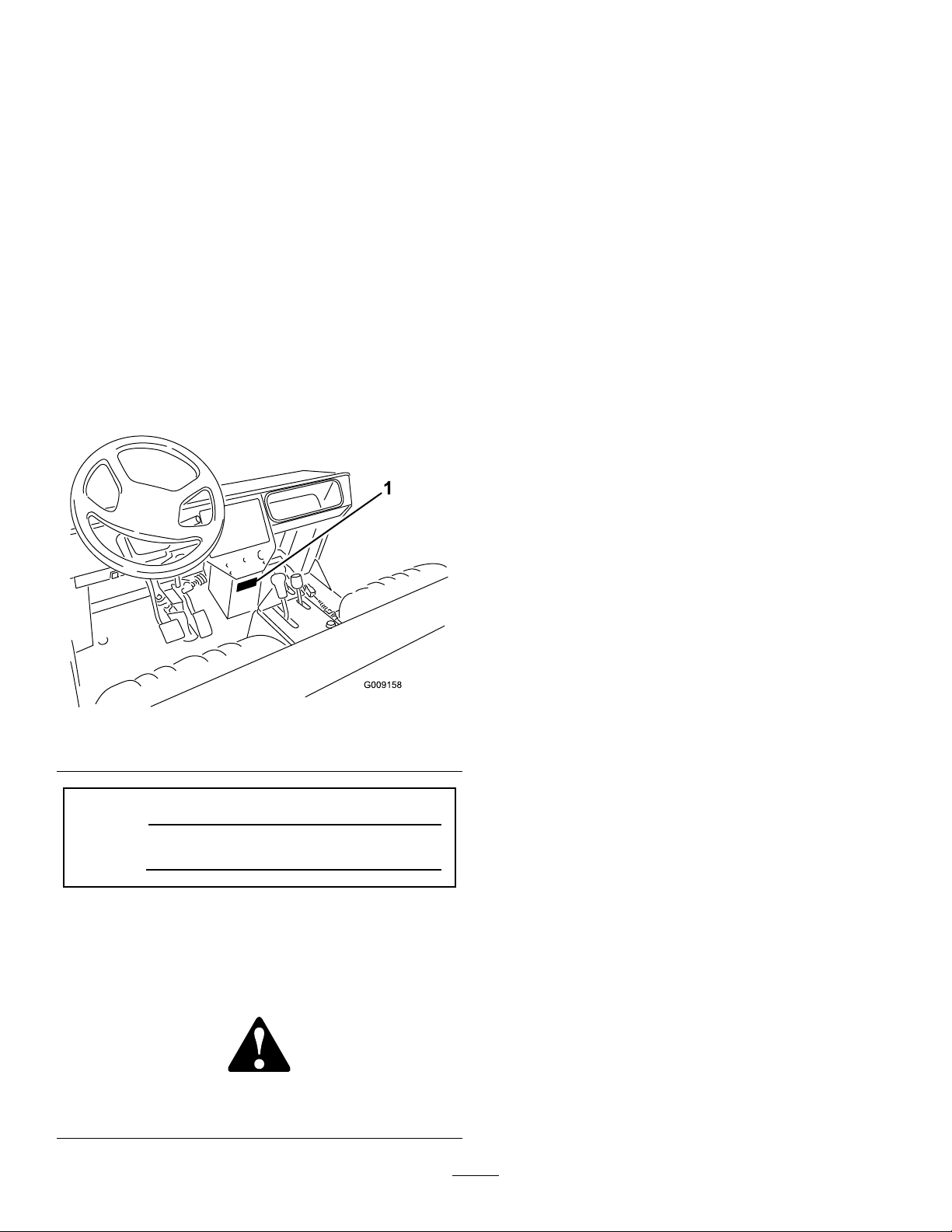
SafetyandInstructionalDecals
Safetydecalsandinstructionsareeasilyvisibletotheoperatorandarelocatednearanyareaof
potentialdanger.Replaceanydecalthatisdamagedorlost.
93-9852
1.Warning—readtheOperator’sManual.2.Crushinghazard—installthecylinderlock.
93-9447
1.Warning—readtheOperator’sManual;removetheignition
93-9448
1.Warning—whenaddingfueltothetank,leave25mm
betweenthefuelandthetopofthetank;readtheOperator’s
Manual.
keybeforeservicingorperformingmaintenanceonthe
engineairintakesystem.
93-9442
1.Maximumtongueweight
is90kg;maximumtrailer
weightis680kg.
2.Forinformationon
transmissionuid,read
theOperator’sManual.
93-9879
1.Storedenergyhazard—readtheOperator’sManual.
93-6687
1.Donotstephere.
93-7814
1.Entanglementhazard,belt—stayawayfrommovingparts.
93-8071
1.Hotsurface/burnhazard—stayasafedistancefromthe
hotsurface.
93-9850
1.Donotrepairorrevise—readtheOperator’sManual.
8
Page 9
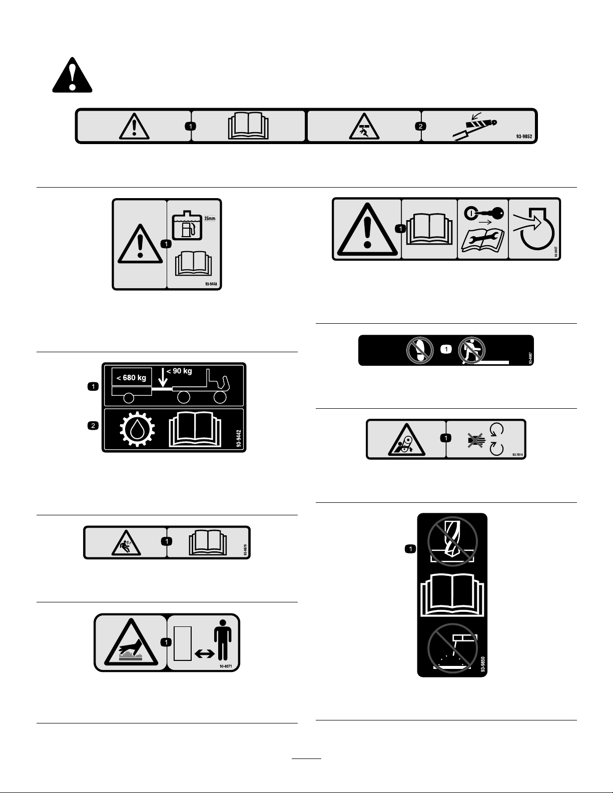
93-9449
1.ReadtheOperator’s
Manual.
2.Greaseevery100hours.
3.Addgrease(9grease
points).
115-2320
1.Warning—donotoperate
thevehicleonpublic
streets,roads,orhighways.
2.Headlights5.Horn8.Hourmeter11.Engine—start
3.Engine—oil6.Battery9.Engine—stop
4.Engine—preheat7.Temperaturelevel10.Engine—run
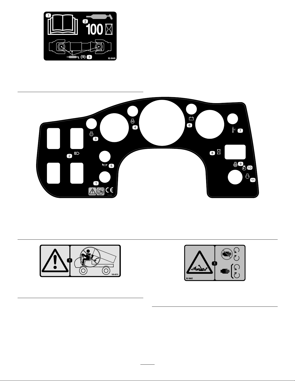
1.Warning—avoidpinchpoints.
105-4215
1.Entanglementhazard,shaft—stayawayfrommovingparts,
keepallguardsandshieldsinplace.
93-9862
9
Page 10
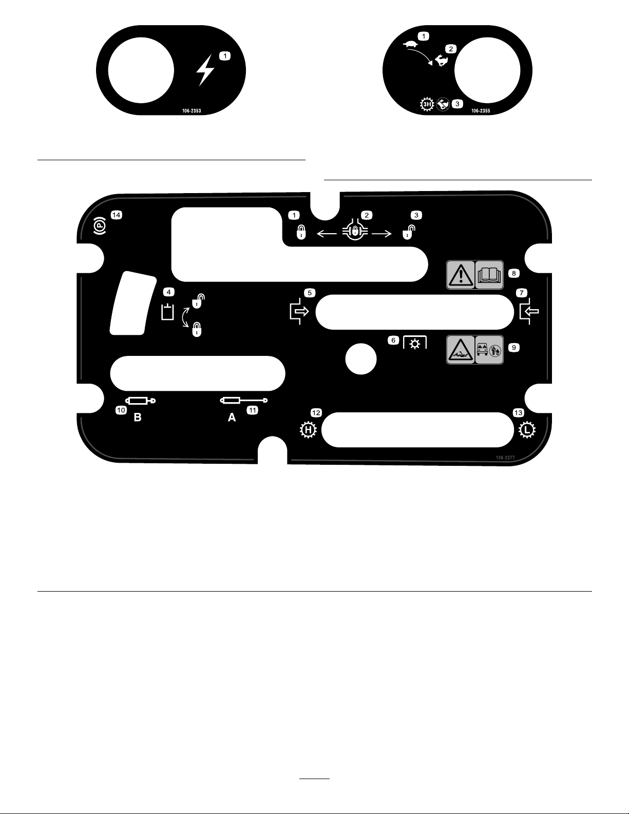
1.Electricalpowerpoint
106-2353
1.Slow
2.Fast
106-2355
3.Transmission—thirdhigh;
nofastspeed
106-2377
1.Locked
2.Differentiallock9.Entanglementhazard,shaft—keepbystander’sasafe
3.Unlocked10.Retracthydraulics
4.Hydrauliclock11.Extendhydraulics
5.Engage12.Transmission—highspeed
6.Powertake-off(PTO)
7.Disengage14.Parkingbrake
8.Warning—readtheOperator’sManual.
distancefromthevehicle.
13.Transmission—lowspeed
10
Page 11
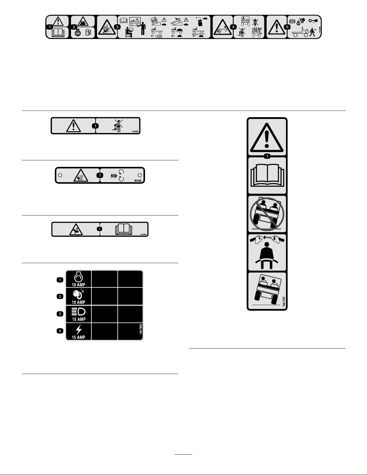
110-2599
1.Warning—readtheOperator’sManual.
2.Firehazard—stoptheenginebeforefueling.
3.Tippinghazard—readtheOperator’sManual,donotoperatethismachineunlessyouaretrained,usecautionanddriveslowly
whendrivingonslopes,slowdownandturngradually ,donotexceed20mph(32kph),anddriveslowlyoverroughterrainor
whencarryingafullorheavyload.
4.Crushing/dismembermenthazardofbystanders—keepbystandersasafedistancefromthevehicle,donotcarrypassengersin
thecargobed,andkeeparmsandlegsinsideofthevehicleatalltimes.
5.Warning—stoptheengineandremovetheignitionkeybeforeleavingthevehicle.
93-6689
1.Warning—donotcarrypassengers.
98-9335
1.Cutting/dismembermenthazard,fan—stayawayfrom
movingparts.
93–9868
1.Crushinghazardofhand—readtheOperator’sManual.
106-7894
1.Engine—start3.Headlights
2.Ignition4.Powerpoint
106-7767
1.Warning—readtheOperator’sManual;avoidtippingthe
machine;weartheseatbelt;leanawayfromthedirection
themachineistipping.
11
Page 12
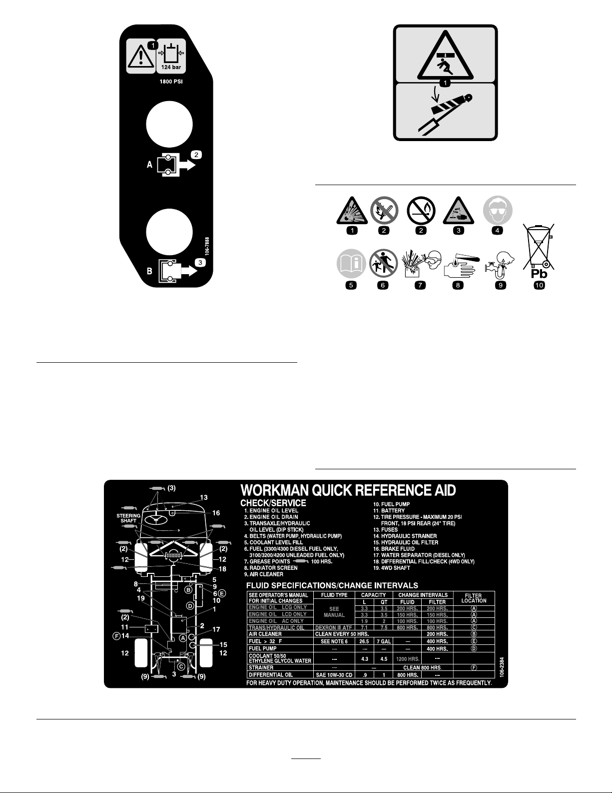
93-9899
93-9899
1.Crushinghazard—installthecylinderlock.
1.Warning—readthe
hydraulicoilpressure
is124bar(1800psi)
2.CouplerA
106-7888
3.CouplerB
BatterySymbols
Someorallofthesesymbolsareonyourbattery
1.Explosionhazard
2.Nore,opename,or
smoking.
3.Causticliquid/chemical
burnhazard
4.Weareyeprotection9.Flusheyesimmediately
5.ReadtheOperator’s
Manual.
6.Keepbystandersasafe
7.Weareyeprotection;
8.Batteryacidcancause
10.Containslead;donot
distancefromthebattery.
explosivegasescan
causeblindnessandother
injuries
blindnessorsevereburns.
withwaterandgetmedical
helpfast.
discard.
106-2384
12
Page 13

Setup
LooseParts
Usethechartbelowtoverifythatallpartshavebeenshipped.
ProcedureDescription
1
2
3
4
5
MediaandAdditionalParts
Rearfender
Bolts,3/8x1–1/4in
Locknut,3/8
Supportplate
Wheelnut10
Frontwheel2
Wheelnut10
Rearwheel2
Steeringwheel
Cap
Washer1
Foamseal1
Frontfender
Sockethexheadbolt,#10x3/4”in.
Washer,.210I.D.20
Locknut,#10
ROPSframe
bolt1/2x3”in.
Locknuts1/2
Qty.
10
10
10
Use
2
2
2
1
1
2
1
4
4
Mounttherearfenders.
Mountthewheels.
Installthesteeringwheel.
Installthefrontfenders.
MounttheROPS(RolloverProtection
System)
Description
Operator’sManual
PartsManual1
Note:Determinetheleftandrightsideofthemachine
fromthenormaloperatingposition.
Qty.
Use
1
Readbeforeoperatingthevehicle
Usetoreferencepartnumbers
1
InstalltheRearFenders
Partsneededforthisprocedure:
2
Rearfender
10
Bolts,3/8x1–1/4in
2
Locknut,3/8
2
Supportplate
Procedure
1.Loosenthelocknutsandboltssecuringtaillight
bracketstorightandleftframebrackets(Figure3).
2.Pivottaillightbracketsrearwardandtightenbolts
andlocknuts.
13
Page 14
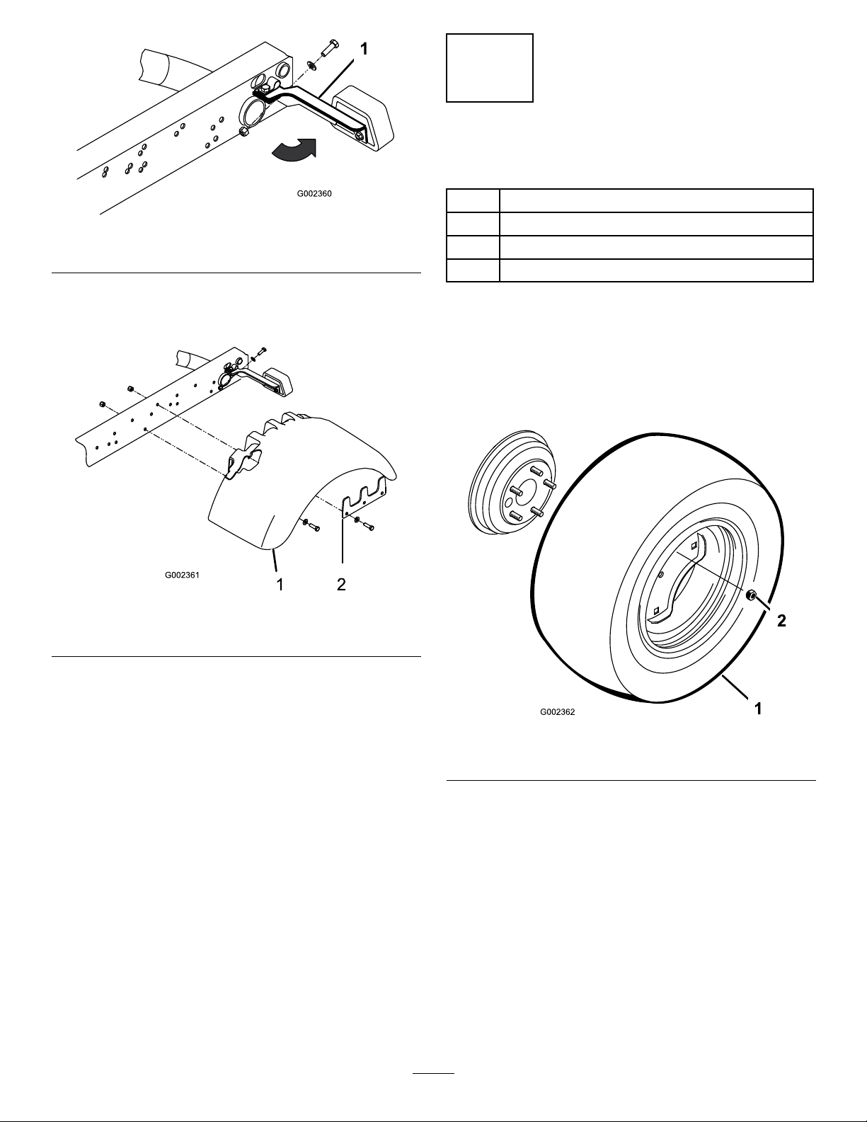
Figure3
1.Fender
3.Securerearofeachtaillightbrackettorearof
framebracketswitha5/16x1in.bolt,.344”I.D .
atwasherandlocknut,asshowninFigure3.
2
InstalltheWheels
Partsneededforthisprocedure:
10Wheelnut
2Frontwheel
10Wheelnut
2Rearwheel
Procedure
1.Removelugnutssecuringwheelstowheelbrackets.
Retainlugnuts.
2.Mountwheelsandinstalllugnuts.T orquelugnuts
to45–65ft-lb.
Figure4
1.Fender
4.Looselysecureafendertoeachsideofframewith
asupportplate,(5)3/8x1–1/4in.bolts,anda
locknutasshowninFigure4.
Note:Weldnutsareinplacetosecure(4)ofthe
bolts.
5.Tightenallfasteners.
2.Supportplate
Figure5
1.Wheel2.Wheelnut
14
Page 15
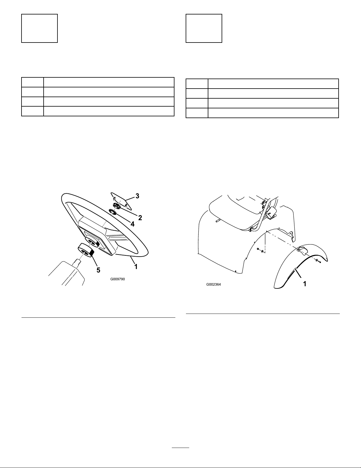
3
4
InstalltheSteeringWheel
Partsneededforthisprocedure:
1
Steeringwheel
1
Cap
1Washer
1Foamseal
Procedure
1.Removethejamnutfromthesteeringshaft.Slide
thefoamseal,steeringwheelandwasheronto
steeringshaft(Figure6).
2.Securesteeringwheeltoshaftwithjamnutand
tightenitto10-15ft-lb.
3.Installcaptosteeringwheel.
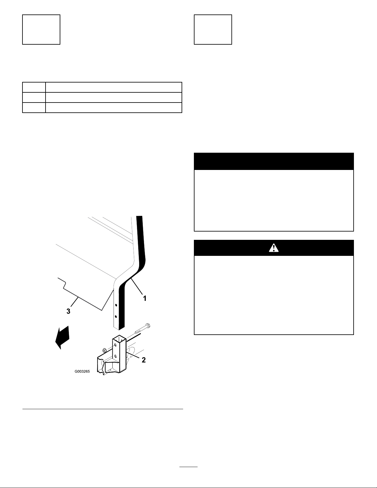
InstalltheFrontFenders
Partsneededforthisprocedure:
2
Frontfender
10
Sockethexheadbolt,#10x3/4”in.
20Washer,.210I.D.
10
Locknut,#10
Procedure
1.Alignthevefendermountingholeswiththeholes
ineachsideofbody(Figure7).
2.Mountafendertoeachsideofbodywith(5)#10x
3/4in.socketheadbolts,(10)atwashersand(5)
#10locknuts.Positionawashernexttobolthead
andlocknut.
Figure6
1.Steeringwheel3.Cap
2.Jamnut4.Washer
Figure7
1.Fender
15
Page 16
5
6
InstallROPS
Partsneededforthisprocedure:
1
ROPSframe
4
bolt1/2x3”in.
4
Locknuts1/2
Procedure
1.InserteachsideofROPSintomountingbracket
oneachsideofvehicleframe,positioningROPSas
showninFigure8.
Note:TheROPScoverplatemountingboltsmay
havetobeloosenedtoinserttheROPSintothe
mountingbrackets.
2.SecureeachsideofROPStomountingbracketswith
(2)1/2–13x3”lg.boltsandlocknuts.
ActivateandChargethe
Battery
NoPartsRequired
Procedure
Ifbatteryisnotlledwithelectrolyteoractivated,it
mustberemovedfromvehicle,lledwithelectrolyte
andcharged.Bulkelectrolytewith1.260specicgravity
canbepurchasedfromalocalbatterysupplyoutlet.
Warning
CALIFORNIA
Proposition65Warning
Batteryposts,terminals,andrelated
accessoriescontainleadandleadcompounds,
chemicalsknowntotheStateofCalifornia
tocausecancerandreproductiveharm.
Washhandsafterhandling.
Figure8
1.ROPS3.ROPScoverplate
2.Mountingbracket
Batteryelectrolytecontainssulfuricacidwhich
isadeadlypoisonandcausessevereburns.
•Donotdrinkelectrolyteandavoidcontact
withskin,eyesorclothing.Wearsafety
glassestoshieldyoureyesandrubbergloves
toprotectyourhands.
•Fillthebatterywherecleanwaterisalways
availableforushingtheskin.
1.Loosenknobssecuringbatterycovertobatterybase
andslidecoveroff.
16
Page 17
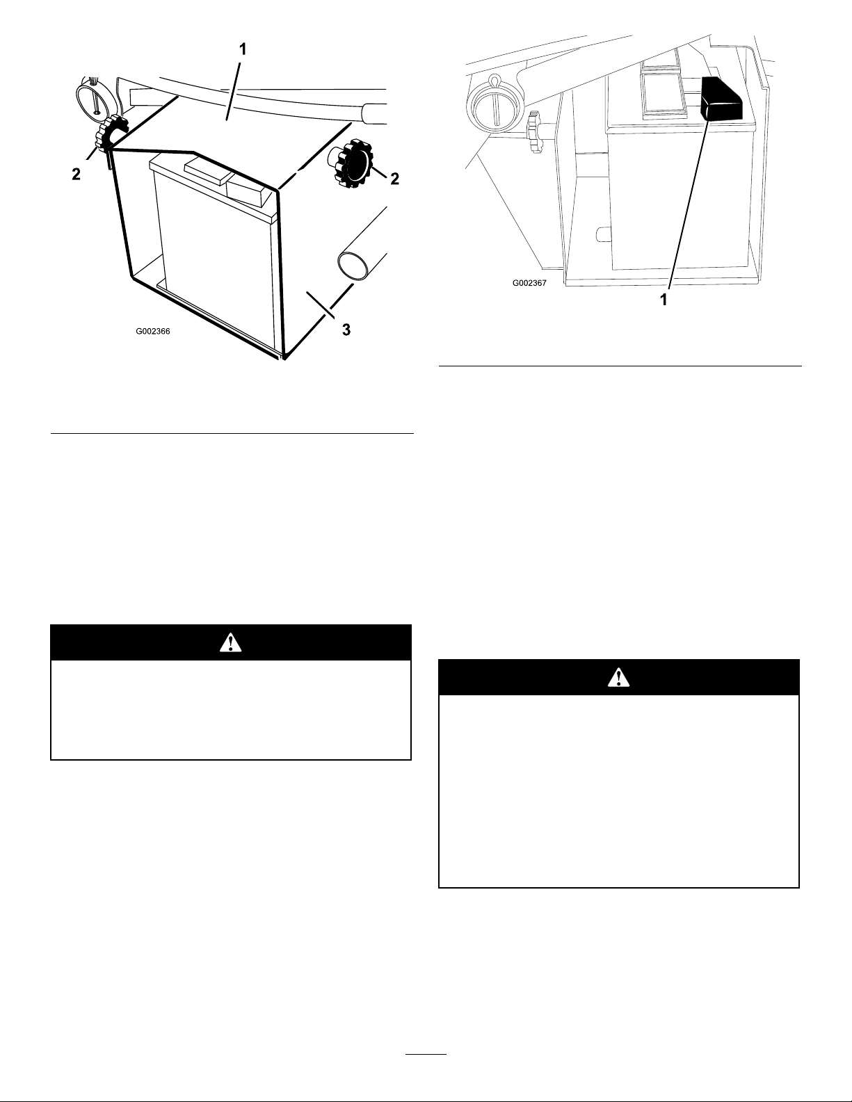
Figure9
1.Batterycover3.Batterybase
2.Knob
2.Removebolt,washersandlocknutsecuringbattery
holddowntobatterybase.Removeholddownand
slidebatteryoutofbatterybase.
3.Removellercapsfrombatteryandslowlylleach
celluntilelectrolyteisjustabovetheplates.
4.Replacellercapsandconnecta3to4ampbattery
chargertothebatteryposts.Chargethebatteryata
rateof3to4amperesfor4to8hours.
Chargingthebatteryproducesgassesthatcan
explode.
Neversmokenearthebatteryandkeepsparks
andamesawayfrombattery.
5.Whenbatteryischarged,disconnectchargerfrom
electricaloutletandbatteryposts.
Figure10
1.Positive(+)cable
6.Removellercaps.Slowlyaddelectrolytetoeach
celluntillevelisuptollring.Installllercaps.
Important:Donotoverllbattery.Electrolyte
willoverowontootherpartsofthevehicleand
severecorrosionanddeteriorationwillresult.
7.Slidebatteryintobatterybasesobatteryterminals
aretowardtherearofthevehicle.
8.Installthepositivecable(red)tothepositive(+)
terminalandthenegativecable(black)tothe
negative(—)terminalofthebatteryandsecure
withboltsandnuts.Slidetherubberbootoverthe
positiveterminaltopreventpossibleshort–outfrom
occurring.
Incorrectbatterycableroutingcoulddamage
themachineandcablescausingsparks.Sparks
cancausethebatterygassestoexplode,
resultinginpersonalinjury.
•Alwaysdisconnectthenegative(black)
batterycablebeforedisconnectingthe
positive(red)cable.
•Alwaysconnectthepositive(red)battery
cable
9.Installbatteryholddownandsecuretobasewith
bolt,washersandlocknut.
10.Reinstallbatterycovertobatterybaseandtighten
knobs.
17
Page 18
7
FullBedRemoval
Thefullbedweighsapproximately325pounds,
sodonottrytoinstallorremoveitbyyourself.
Useanoverheadhoistorgetthehelpoftwoor
threeotherpeople.
NoPartsRequired
Procedure
1.Startengine.Engagehydraulicliftleverandlower
beduntilcylindersarelooseinslots.Releaseliftlever
andturnoffengine.
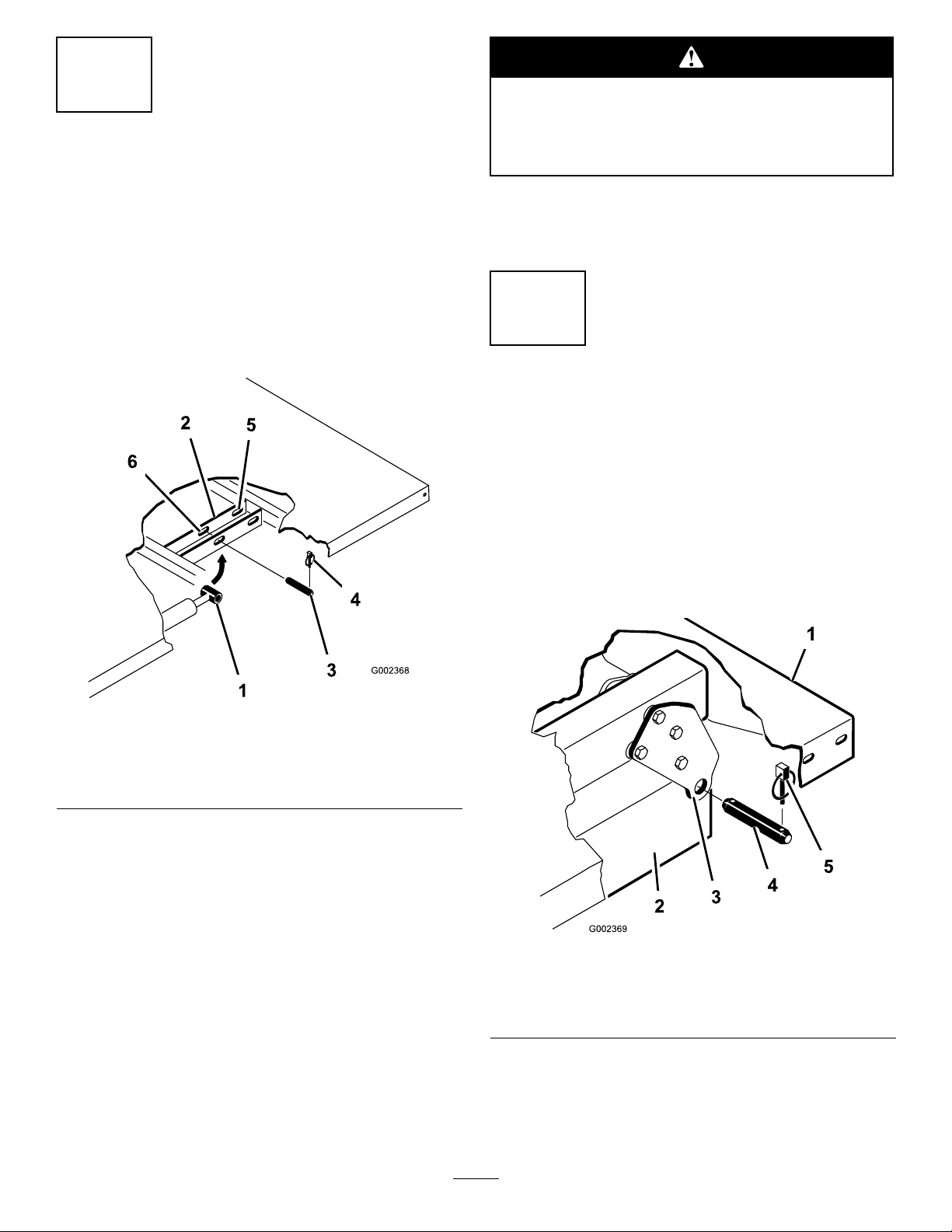
2.Removelynchpinsfromouterendsofcylinderrod
clevispins(Figure11).
6.Storecylindersinstorageclips.Engagehydrauliclift
lockleveronvehicletopreventaccidentalextension
ofliftcylinders.
8
Re-InstalltheFullBed
NoPartsRequired
Procedure
Note:Ifbedsideswillbeinstalledonatbed,itis
easiertoinstallthembeforebedisinstalledonvehicle.
Note:Assurerearpivotplatesareboltedtothebed
frame/channelsothatlowerendanglestotherear
(Figure12).
Figure11
1.Bedmountingplate4.Lynchpin
2.Cylinderrodend5.Rearslots(Fullbed)
3.Clevispin6.Frontslots(2/3bed)
3.Removeclevispinssecuringcylinderrodendsto
bedmountingplatesbypushingpinstowardsinside
(Figure12).
4.Removelynchpinsandclevispinssecuringpivot
bracketstoframechannels(Figure12).
5.Liftbedoffvehicle.
Figure12
1.Leftrearcornerofbed4.Clevispin
2.Vehicleframechannel
3.Pivotplate
Note:Makesurespacerbracketsandwearblocks
(Figure13)areinstalledorradiatorcovermaybe
damaged.Carriageboltsheadstobepositionedinside
themachine.
5.Lynchpin
18
Page 19

ProductOverview
Thefullbedweighsapproximately325pounds,
sodonottrytoinstallorremoveitbyyourself.
Useanoverheadhoistorgetthehelpoftwoor
threeotherpeople.
Figure13
1.Spacerbracket3.Carriagebolt
2.Wearblock
Controls
Note:Determinetheleftandrightsideofthemachine
fromthenormaloperatingposition.
AcceleratorPedal
Theacceleratorpedal(Figure14)givestheoperatorthe
abilitytovaryengineandgroundspeedofthevehicle,
whenthetransmissionisingear.Depressingthepedal
increasesengineRPMandgroundspeed.Releasing
pedalwilldecreaseengineRPMandgroundspeedof
themachine.
1.Assureliftcylindersarefullyretracted.
2.Carefullysetbedontovehicleframealigningrearbed
pivotplateholeswithholesinrearframechannel
andinstall(2)clevispinsandlynchpins(Figure12).
3.Withbedlowered,secureeachcylinderrodend,to
appropriateslotsinbedmountingplateswithclevis
pinandlynchpin.Insertclevispinfromoutsideof
bedwithlynchpintowardoutside(Figure12).Rear
slotsareforfullbedinstallationandfrontslotsare
for2/3bedinstallation.
Note:Enginemayneedtobestartedtoextend
orretractcylindersforalignmentwithholes.Keep
ngersout!
Note:Unusedslotcanbepluggedwithaboltand
nuttopreventassemblyerrors.
4.Startengineandengagehydraulicliftlevertoraise
bed.Releaseliftleverandturnoffengine.Installthe
bedsafetysupporttopreventaccidentalloweringof
thebed.RefertoUsingBedSafetySupport.
5.Installlynchpinstoinsideendsofclevispins.
Figure14
1.Acceleratorpedal3.Brakepedal
2.Clutchpedal
ClutchPedal
Theclutchpedal(Figure14)mustbefullydepressed
todisengageclutchwhenstartingengineorshifting
transmissiongears.Releasepedalsmoothlywhen
transmissionisingeartopreventunnecessarywearon
transmissionandotherrelatedparts.
Important:Donotrideclutchpedalduring
operation.Clutchpedalmustbefullyoutorclutch
willslipcausingheatandwear.Neverholdthe
vehiclestoppedonahillusingtheclutchpedal.
Damagetotheclutchmayoccur.
BrakePedal
Thebrakepedal(Figure14)isusedtoapplyservice
brakestostoporslowvehicle.
Note:Ifautomatictailgatereleasehasbeen
installedonbed,makesurefrontdumplinkrodhas
beenplacedoninsideofleftsideclevispinbefore
lynchpinisinstalled.
19
Page 20

Wornormisadjustedbrakesmayresultin
personalinjury.Ifbrakepedaltravelstowithin
1–1/2”ofthevehicleoorboard,thebrakes
mustbeadjustedorrepaired.
GearShiftLever
Fullydepressclutchpedalandmoveshiftlever(@@@5)
intodesiredgearselection.Adiagramoftheshift
patternisindicatedbelow .
Important:Donotshiftthetransaxletothereverse
orforwardgearunlessthevehicleisstandingstill.
Damagetotransaxlemayoccur.
Downshiftingfromtoohighaspeedcan
causetherearwheelstoskidresultinginloss
ofvehiclecontrolaswellasclutchand/or
transmissiondamage.Shiftsmoothlytoavoid
grindinggears.
DifferentialLock
Allowsrearaxletobelockedforincreasedtraction.
Differentiallock(Figure16)maybeengagedwith
vehicleinmotion.Moveleverforwardandtotheright
toengagelock.
Figure16
1.Gearshiftlever4.Hydraulicliftlock
2.Parkingbrake
3.Hydraulicbedlift6.High–lowrangeshifter
5.Differentiallock
ParkingBrake
Whenevertheengineisshutoff,theparkingbrake
(Figure16)mustbeengagedtopreventaccidental
movementofthevehicle.Toengagetheparkingbrake,
pullbackonlever.Todisengage,pushleverforward.
Makesureparkingbrakeisreleasedbeforemoving
vehicle.Ifvehicleisparkedonasteepgrade,makesure
parkingbrakeisapplied.Also,shiftthetransmission
into1stgearonauphillgradeorreverseonadownhill
grade.Placechocksatthedownhillsideofwheels.
HydraulicLift
Raisesandlowersbed.Moverearwardtoraise,forward
tolower(Figure16).
Important:Whenloweringbed,holdleverin
forwardpositionfor1or2secondsafterbed
contactsframetosecureitinloweredposition.
Donotholdthehydraulicliftineithertheraiseor
lowerposition,formorethan5seconds,oncethe
cylindershavereachedtheendoftheirtravel.
HydraulicLiftLock
Note:Vehiclemotionplusaslightturnisrequiredto
engageordisengagedifferentiallock.
Turningwiththedifferentiallockoncanresult
inlossofvehiclecontrol.Donotoperatewith
differentiallockonwhenmakingsharpturnsor
athighspeeds.Refertousingthedifferential
lock.
Locksliftleversohydrauliccylindersdonotoperate
whenvehicleisnotequippedwithabed(Figure16).
ItalsolocksliftleverinONpositionwhenusingthe
hydraulicsforattachments.
High–LowRangeShifter
Addsthreeadditionalspeedsforprecisespeedcontrol
(Figure16).
•Vehiclemustbecompletelystoppedbeforeshifting
betweenHighandLowrange.
•Shiftonlyonlevelground.
20
Page 21

•Depressclutchpedalfully.
•MoveleverfullyforwardforHighandfullyrearward
forLow .
HIGHisforhigherspeeddrivingonlevel,drysurfaces
withlightloads.
LOWisforlowspeeddriving.Usethisrangewhen
greaterthannormalpowerorcontrolisrequired.For
example,steepgrades,difcultterrain,heavyloads,slow
speedbuthighenginespeed(spraying).
Important:ThereisalocationbetweenHIGHand
LOWinwhichthetransaxleisinneitherrange.
Thisshouldnotbeusedasaneutralposition
becausethevehiclecouldmoveunexpectedlyifthe
HIGH–LOWshifterisbumpedandthegearshift
leverisingear.
CoolantTemperatureGaugeandLight
Registerscoolanttemperatureinengine.Operatesonly
whenignitionswitchisinOnposition(Figure17).
Indicatorlightwillilluminateifengineoverheats.
ChargeIndicator
Illuminateswhenbatteryisbeingdischarged.Iflight
illuminatesduringoperation,stopvehicle,turnoff
engineandcheckforpossiblecauses,suchasalternator
belt(Figure17).
starts.ThekeywillmoveautomaticallytotheON
position.Toshutengineoff,rotatekeycounterclockwise
toOFFposition.
Figure17
1.Chargeindicator
2.Coolanttemperature
gauge&light
3.Hourmeter
4.Ignitionswitch
5.3rdhighlockoutswitch
Important:Ifalternatorbeltislooseorbroken,do
notoperatevehicleuntiladjustmentorrepairis
complete.Failuretoobservethisprecautionmay
resultindamagetotheengine.
Tocheckoperationofwarninglights:
•Applyparkingbrake.
•Turnignitionkeyto“ON”,butdonotstartengine.
Thecoolanttemperature,chargeindicatorandoil
pressurelightsshouldglow.Ifanylightdoesnot
function,eitherabulbisburnedoutorthereisa
malfunctioninthesystemwhichmustberepaired.
HourMeter
Indicatesthetotalhoursofmachineoperation.The
hourmeter(Figure17)startstofunctionwheneverthe
keyswitchisrotatedto“ON”positionorifengineis
running.
IgnitionSwitch
Theignitionswitch(Figure17),usedtostartandstop
theengine,hasthreepositions:OFF ,RUN(GLOW)
andSTART .Rotatekeyclockwise—STARTposition
—toengagestartermotor.Releasekeywhenengine
3rdHighLockoutSwitch
Movingswitch(Figure17)toslowpositionand
removingkeywillpreventuseofthirdgearwheninthe
Highrange.Enginewillshutoffifshiftleverismoved
tothirdgearwheninHighrange.Keyisinstalledwith
teethpointingdownward.Pushkeyintoturn.Keyis
removableineitherposition.
GlowPlugIndicator
Glowplugindicator(Figure18)willglowredwhenthe
glowplugsareactivated.
Important:Theglowplugindicatorwillturn
on,foranadditional15seconds,whentheswitch
returnstotheSTARTposition.
LightSwitch
Toggleswitch(Figure18)toactivateheadlights.Push
toturnlights“ON”.
OilPressureWarningLight
Lightglows(Figure18)ifengineoilpressuredrops
belowasafelevelwhileengineisrunning.Iflight
21
Page 22

ickersorremainsON,stopvehicle,turnoffengineand
checkoillevel.Ifoillevelwaslow ,butaddingoildoes
notcauselighttogooutwhenengineisrestarted,turn
engineoffimmediatelyandcontactyourlocalTORO
distributorforassistance.
Tocheckoperationofwarninglights:
1.Applyparkingbrake.
2.Turnignitionkeyto“ON”,butdonotstartengine.
Theoilpressurelightshouldglowred.Iflightdoes
notfunction,eitherabulbisburnedoutorthereisa
malfunctioninthesystemwhichmustberepaired.
Note:Ifenginewasjustturnedoff,itmaytake1to2
minutesforlighttocomeon.
1.Passengerhandhold
SeatAdjustingLever
Figure19
2.Storagecompartment
FuelGauge
Showsamountoffuelintank.Operatesonlywhen
ignitionswitchisin“ON”position(Figure18).
Figure18
1.Lightswitch
2.Oilpressurewarninglight5.Tachometer(Optional)
3.Fuelgauge6.Horn
4.Glowplugindicatorlight
HornButton
Pressingbuttonactivateshorn(Figure18).
Tachometer
Optional(Figure18).
PassengerHandHold
Ondashboard(Figure19).
Theseatscanbeadjustedforeandaftforoperator
comfort(Figure20).
Figure20
1.Seatadjustinglever
Specications
Note:Specicationsanddesignaresubjecttochange
withoutnotice.
Dimensions
OverallWidth
OverallLength
BaseWeight(Dry
w/oatbed)
RatedCapacity
(includes200lb.
operator,200lb.
passengerandloaded
attachment).
Maximum.Gross
VehicleWeight
TowCapacity
63”
128.25”w/obed
130.38”w/fullbed
136.38”w/2/3bedinrearmounting
location
Model07362–1929lbs.
Model07364–2029lbs.
Model07362–2321lbs.
Model07364–2221lbs.
4,250lbs.
Tongueweight200lbs.
Maximumtrailerweight1,500lbs.
22
Page 23

Dimensions(cont'd.)
GroundClearance7”w/noload
WheelBase70”
WheelTread(center
linetocenterline)
Height
Front46”
Rear47.7”
75”totopofROPS
Attachments/Accessories
AselectionofToroapprovedattachmentsand
accessoriesareavailableforusewiththemachineto
enhanceandexpanditscapabilities.Contactyour
AuthorizedServiceDealerorDistributororgoto
www.Toro.comforalistofallapprovedattachments
andaccessories.
Operation
Note:Determinetheleftandrightsidesofthe
machinefromthenormaloperatingposition.
Beforeservicingormakingadjustmentstothe
machine,stopengine,setparkingbrakeand
removekeyfromtheswitch.Anyloadmaterial
mustberemovedfrombedorotherattachment
beforeworkingunderraisedbed.Neverwork
underaraisedbedwithoutpositioningsafety
supportonafullyinstalledcylinderrod.
CheckCrankcaseOil
ServiceInterval:Beforeeachuseordaily
Aftertherst50hours
Every150hours
Theengineisshippedwithapproximately3.5quarts
(w/lter)ofoilinthecrankcase;however,levelofoil
mustbecheckedbeforeandaftertheengineisrst
started.
Note:Thebesttimetochecktheengineoiliswhen
theengineiscoolbeforeithasbeenstartedforthe
day.Ifithasalreadybeenrun,allowtheoiltodrain
backdowntothesumpforatleast10minutesbefore
checking.Iftheoillevelisatorbelowthe“add”mark
onthedipstick,addoiltobringtheoilleveltothe“full”
mark.DONOTOVERFILL.Iftheoillevelisbetween
the“full”and“add”marks,nooiladditionisrequired.
1.Positionmachineonalevelsurface.
2.Removedipstickandwipeitwithacleanrag.Insert
dipstickintotubeandmakesureitisseatedfully .
Removedipstickandchecklevelofoil.
23
Page 24

Figure21
1.Dipstick
3.Theengineusesanyhigh-quality10W30detergent
oilhavingtheAmericanPetroleumInstitute-API“serviceclassication”CForhigher.Choosea
viscosityaccordingtothetableinFigure22.
Note:Whenaddingoil,removedipsticktoallow
properventing,pouroilslowlyandcheckthelevel
oftenduringthisprocess.DONOTOVERFILL.
Important:Whenaddingengineoilorlling
oil,theremustbeclearancebetweentheoilll
deviceandtheoilllholeinthevalvecoveras
showninFigure24.Thisclearanceisnecessary
topermitventingwhenlling,whichprevents
oilfromoverrunningintobreather.
Figure22
4.Ifoillevelislow,removellercapandaddenough
oiltoraiseleveltoFULLmarkondipstick.
Figure23
1.Fillercap
Figure24
5.Installthedipstickrmlyinplace.
Important:Checklevelofoilevery8operating
hoursordaily.Changeoilandlterinitiallyafter
therst50hoursofoperation,thereafter,change
oilandlterevery150hours.However,change
oilmorefrequentlywhenengineisoperatedin
extremelydustyordirtyconditions.
Note:Afterllingorchangingoil,startandrunthe
engineatidlefor30seconds.Shutengineoff.W ait30
secondsandcheckoillevel.Addenoughoiltoraise
leveltoFULLmarkondipstick.
FillFuelTank
Fueltankcapacityisapproximately7gallons.
TheenginerunsonNo.2–Dor1–Dautomotivetype
dieselfuelwithaminimumcetaneratingof40.
Note:Highercetaneratedfuelmayberequired
ifmachineistobeusedathighaltitudesand
low-atmospherictemperatures.
1.Cleanareaaroundfueltankcap.
2.Removefueltankcap.
24
Page 25

Undercertainconditions,dieselfuelandfuel
vaporsarehighlyammableandexplosive.A
reorexplosionfromfuelcanburnyouand
othersandcancausepropertydamage.
•Useafunnelandllthefueltankoutdoors,
inanopenarea,whentheengineisoffand
iscold.Wipeupanyfuelthatspills.
•Donotllthefueltankcompletelyfull.Add
fueltothefueltankuntilthelevelis1in.
(25mm)belowthebottomofthellerneck.
Thisemptyspaceinthetankallowsthefuel
toexpand.
•Neversmokewhenhandlingfuel,andstay
awayfromanopenameorwherefuel
fumesmaybeignitedbyaspark.
•Storefuelinaclean,safety-approved
containerandkeepthecapinplace.
3.Filltanktoaboutoneinchbelowtopoftank,
(bottomofllerneck).DONOTOVERFILL.
Theninstallcap.
Iftheenginehasbeenrunning,thepressurized,
hotcoolantcanescapeandcauseburns.
•Donotopentheradiatorcapwhenthe
engineisrunning.
•Allowenginetocoolatleast15minutes
oruntiltheradiatorcapiscoolenoughto
touchwithoutburninghand.
•Usearagwhenopeningtheradiatorcap,
andopenthecapslowlytoallowsteamto
escape.
2.Checkcoolantlevel.Coolantshouldbeupto
COLDlineonreservetank,whenengineiscold.
4.Wipeupanyfuelthatmayhavespilledtopreventa
rehazard.
Figure25
1.Fueltankcap
CheckCoolingSystem
ServiceInterval:Beforeeachuseordaily
Capacityofcoolingsystemisapproximately4qts.
Thecoolingsystemislledwitha50/50solutionof
waterandpermanentethyleneglycolanti–freeze.
1.Parkmachineonalevelsurface.
Figure26
1.Reservetank
2.Hotline
3.Coldline
3.Ifcoolantislow,removereservetankcapandadd
a50/50mixtureofwaterandpermanentethylene
glycolanti–freeze.DONOTOVERFILL.
4.Installreservetankcap.
CheckTransaxle/Hydraulic
Fluid
ServiceInterval:Beforeeachuseordaily
ThetransaxlereservoirislledwithDexronIIlATF .
Checklevelbeforeengineisrststartedandevery8
hoursordaily ,thereafter.Capacityofsystemis7.5qt.
1.Positionthevehicleonalevelsurface.
2.Cleanareaarounddipstick.
3.Unscrewdipstickfromtopoftransaxleandwipe
itwithacleanrag.
25
Page 26

CheckTorqueOfWheelNuts
ServiceInterval:Aftertherst2hours
Aftertherst10hours
Every200hours
Failuretomaintainpropertorqueofthewheel
nutscouldresultinfailureorlossofwheeland
mayresultinpersonalinjury.
Torquethefrontandrearwheelnutsto45–65
Figure27
1.Dipstick
ft.-lb.
4.Screwdipstickintotransaxleandmakesureitis
seatedfully.Unscrewdipstickandcheckuidlevel.
Fluidshouldbeuptotopofatportionofdipstick.
Iflevelislow ,addenoughuidtoachievethe
properlevel.
CheckFrontDifferentialOil
Fourwheeldriveonly
ServiceInterval:Every100hours/Monthly
(whichevercomesrst)
Thedifferentialislledwith10W30oil.Capacityof
systemis1qt.
1.Positionthevehicleonalevelsurface.
2.Cleanareaaroundll/checkplugonsideof
differential.
3.Removell/checkplugandchecklevelofoil.Oil
shouldbeuptohole.Ifoilislow,add10W30oil.
4.Re–installll/checkplug.
CheckTirePressure
ServiceInterval:Beforeeachuseordaily
Maximumairpressureinfronttiresis20psiandrear
(24”)tiresis18psi.
1.Theairpressureneededisdeterminedbythe
payloadcarried.
2.Thelowertheairpressure,thelessthecompaction
andtiremarksareminimized.Lowerpressure
shouldnotbeusedforheavypayloadsathigh
speeds.Tiredamagemayresult.
3.Higherpressuresshouldbeusedforheavier
payloadsathigherspeeds.Donotexceedthe
maximumpressure.
CheckBrakeFluid
ServiceInterval:Beforeeachuseordaily
Every1,000hours/Every2years
(whichevercomesrst)
Thebrakeuidreservoirisshippedfromthefactory
lledwith“DOT3”brakeuid.Checklevelbefore
engineisrststartedandevery8hoursordaily ,
thereafter.
1.Frontdifferential
2.Fill/checkplug
1.Parkmachineonalevelsurface.
2.Loosenknobsecuringcupholdertodash
(Figure29).Removecupholderfromdash.
Figure28
3.Drainplug
26
Page 27

Figure29
1.Cupholder
3.FluidlevelshouldbeuptoFULLlineonreservoir.
2.Knob
Pre–startingChecks
Safeoperationbeginsbeforetakingthevehicleoutfor
aday’swork.Youshouldchecktheseitemseachtime:
•Checktirepressure.
Note:Thesetiresaredifferentthancartires,they
requirelesspressuretominimizeturfcompaction
anddamage.
•Checkalluidlevelsandaddtheappropriate
amountofTorospecieduids,ifanyarefound
tobelow .
•Checkthefrontoftheradiator.Removeanydebris
andcleantheradiatorscreen.
•Checkbrakepedaloperation.
•Checktoseethatthelightsandhornareworking.
•Turnsteeringwheeltotheleftandrighttocheck
steeringresponse.
•Checkforoilleaks,loosepartsandanyother
noticeablemalfunctions.Makesureengineisoff
andallmovingpartshavestoppedbeforechecking
foroilleaks,loosepartsandothermalfunctions.
Figure30
1.Brakeuidreservoir
4.Ifuidlevelislow,cleanareaaroundcap,remove
reservoircapandlltoproperlevel.DONOT
OVERFILL.
5.Reinstallcupholdertodash.
CheckFanBeltTension
Checkallbeltsforwear,crackingorimpropertension.
Checktensionbydepressingbeltatmidspanoffan
anddriveshaftpulleyswith22lbs.offorce.Anew
beltshoulddeect.48–.58in.Ausedbeltshould
deect.55–.65in.Ifdeectionisincorrect,proceedto
page45fortensioningprocedure.Ifcorrect,continue
operation.
Important:Improperbelttensionmayresultin
increasedsteeringeffort.
Ifanyoftheaboveitemsarenotcorrect,notifyyour
mechanicorcheckwithyoursupervisorbeforetaking
thevehicleoutfortheday .Yoursupervisormaywant
youtocheckotheritemsonadailybasis,soaskwhat
yourresponsibilitiesare.
StartingEngine
•Initialstartupofanewmachine.
•Enginehasceasedrunningduetolackoffuel.
•Maintenancehasbeenperformeduponfuelsystem
components;i.e.,lterreplaced,separatorserviced,
etc.
RefertoBleedingTheFuelSystem.
1.Sitonoperator’sseatandengageparkingbrake.
2.DisengagePTO(ifsoequipped)andreturnhand
throttlelevertoOFFposition(ifsoequipped).
3.MoveshiftlevertoNEUTRALpositionand
depressclutchpedal.
4.Makesurethehydraulicliftleverisinthecenter
position.
5.Keepfootoffacceleratorpedal.
6.TurnignitionswitchtoONposition.Whenglow
plugindicatorlightgoesoff,engineisreadyto
START.
7.RotateignitionkeyswitchtoSTARTposition
Releasekeyimmediatelywhenenginestartsand
allowittoreturntoRUNposition.
27
Page 28

Note:Theglowplugindicatorwillturnon,foran
additional15seconds,whentheswitchreturnstothe
STARTposition.
Note:Donotrunstartermotormorethan10seconds
atatimeorprematurestarterfailuremayresult.If
enginefailstostartafter10seconds,turnkeytoOFF
position.Recheckcontrolsandprocedures,wait10
additionalsecondsandrepeatstartingoperation
DrivingVehicle
1.Releaseparkingbrake.
2.Fullydepressclutchpedal.
3.Movegearshiftleverto1stgear.
4.Releaseclutchpedalsmoothlywhiledepressing
acceleratorpedal.
5.Whenvehiclegainsenoughspeed,removefoot
fromacceleratorpedal,fullydepressclutchpedal,
movegearshiftlevertonextgearandreleaseclutch
pedalwhiledepressingacceleratorpedal.Repeat
procedureuntildesiredspeedisattained.
Note:Alwaysstopvehiclebeforeshiftingto
reverseorforward.
Usethechartbelowtodeterminethegroundspeed
ofthevehicleat3600RPM.
Gear
1L82.83:12.94.7
2L54.52:14.57.2
3L31.56:1
1H32.31:17.612.2
2H21.27:111.518.5
3H12.31:119.831.9
RL86.94:12.84.5
RH33.91:17.111.6
RangeRatio
Speed
(mph)
7.7
Speed
(kmh)
12.5
StoppingEngine
Tostopengine,rotateignitionkeytoOFFandengage
parkingbrake.Removekeyfromswitchtoprevent
accidentalstarting.
NewVehicleBreak–in
YourW orkmanisreadyforwork.T oprovideproper
performanceandlongvehiclelife,followthese
guidelinesfortherst100operatinghours.
•Checktheuidandengineoillevelsregularly
andbealertforindicationsofoverheatinginany
componentofthevehicle.
•Afterstartingacoldengine,letitwarmupforabout
15secondsbeforeshiftingintogear.
•Avoidracingtheengine.
•Toassureoptimumperformanceofthebrake
system,burnish(break–in)thebrakesbeforeuse.
Toburnishbrakes:Operatethevehicleatfullspeed
for3minutes,applythebrakesfor30secondswhile
drivingin1stgear.Repeatthesesteps20to30
times.T overifythebrakesarecompletelyburnished
removeareartireandinspectthebrakedrumfor
residue.Theresiduecolorshouldbelightgreyto
almostwhitecolor.
•Varyvehiclespeedsduringoperation.Avoid
excessiveidling.Avoidfaststartsandquickstops.
•Abreak–inoilfortheengineisnotrequired.
Originalengineoilisthesametypespeciedfor
regularoilchanges.
•RefertoMaintenancesectionofOperator’sManual
foranyspeciallowhourchecks.
CheckInterlockSystem
Thepurposeoftheinterlocksystemistopreventthe
enginefromcrankingorstartingunlesstheclutchpedal
isdepressed.
Note:Avoidlongperiodsofengineidling.
Important:Donotholdfrontwheelsturned
againsttherightorleftstopsforlongerthan
5seconds.
6.Donotattempttopushortowvehicletogetit
started.Damagetodrivetraincouldresult.
StoppingVehicle
Tostopmachine,removefootfromacceleratorpedal,
depressclutchpedal,thendepressbrakepedal.
Toverifyclutchinterlockswitchoperation:
1.Sitonoperator’sseatandengageparkingbrake.
MoveshiftlevertoNEUTRALposition.
Note:Enginewillnotcrankifhydraulicliftlever
islockedintheforwardposition.
2.Withoutdepressingclutchpedal,rotatekey
clockwisetostartposition.
3.Ifenginecranksorstarts,thereisamalfunctionin
theinterlocksystemthatmustberepairedbefore
operatingvehicle.
Toverifyhydraulicliftleverinterlock:
28
Page 29

1.Sitonoperator’sseatandengageparkingbrake.
MoveshiftlevertoNEUTRALposition.Makesure
thehydraulicliftleverisinthecenterposition.
2.Depressclutchpedal.
3.Movethehydraulicliftleverforwardandrotatekey
clockwisetostartposition.
4.Ifenginecranksorstarts,thereisamalfunctionin
theinterlocksystemthatmustberepairedbefore
operatingvehicle.
Ifsafetyinterlockswitchesaredisconnected
ordamagedthemachinecouldoperate
unexpectedlycausingpersonalinjury.
•Donottamperwiththeinterlockswitches.
•Checktheoperationoftheinterlock
switchesdailyandreplaceanydamaged
switchesbeforeoperatingthemachine.
RefertoAttachmentOperator’sManualforprocedure
oncheckingattachmentinterlocksystem.
OperatingCharacteristics
Driverandpassengershouldalwaysusetheseatbelts.
Ifyouarenotexperiencedatdrivingthevehicle,
practicedrivingitinasafeareaawayfromother
people.Besureyouarefamiliarwithallthevehicle’s
controls,particularlythoseusedforbraking,steering
andtransmissionshifting.Learnhowyourvehicle
handlesondifferentsurfaces.Youroperatingskills
willimprovewithexperience,butasinoperatingany
vehicle,takeiteasyasyoubegin.Besureyouknow
howtostopquicklyinanemergency.Ifyouneedhelp,
askyoursupervisorforassistance.
Manyfactorscontributetoaccidents.Youhavecontrol
overseveralofthemostimportant.Youractions,
suchasdrivingtoofastforconditions,brakingtoo
fast,turningtoosharp,andcombinationsofthese,are
frequentcauseofaccidents.
Oneofthemajorcausesofaccidentsisfatigue.Besure
totakeoccasionalbreaks.Itisveryimportantthatyou
stayalertatalltimes.
Neveroperatethevehicle,oranyequipment,ifyou
areundertheinuenceofalcoholorotherdrugs.
Evenprescriptiondrugsandcoldmedicinescancause
drowsiness.Readthelabelonthemedicineorcheck
withyourdoctororpharmacistifyouareunsureabout
acertainmedication.
Thevehicleisdesignedwithsafetyinmind.Ithasfour
wheelsforaddedstability.Itusesfamiliarautomotive
stylecontrols,includingthesteeringwheel,brakepedal,
clutchpedal,acceleratorpedal,andgearshifter.Itis
importanttoremember,however,thatthisvehicleis
notapassengercar.Itisaworkvehicleandisdesigned
foroffroaduseonly.
TheWORKMANisanoff–highwayvehicle
only,andisnotdesigned,equipped,or
manufacturedforuseonpublicstreets,roads
orhighways.
Thevehiclehasspecialtires,lowgearratios,alocking
differential,andotherfeaturesthatgiveitextratraction.
Thesefeaturesaddtotheversatilityofthevehiclebut,
theycanalsogetyouintodangeroussituations.You
mustkeepinmindthatthevehicleisnotarecreation
vehicle.Itisnotanallterrainvehicle.And,itis
denitelynotmeantfor“stuntdriving”or“horsing
around”.Itisaworkvehicle,notaplayvehicle.
Childrenshouldnotbeallowedtooperatethevehicle.
Anyonewhooperatesthevehicleshouldhaveamotor
vehiclelicense.
Oneofthemostimportantrulestofollowistogo
slowerinunfamiliarareas.Itissurprisinghowmuch
damageandinjurycommonthingscancause.Tree
branches,fences,wires,othervehicles,treestumps,
ditches,sandtraps,streams,andotherthingsfoundin
mostparksandgolfcoursescanbehazardoustothe
operatorandpassenger.
Avoiddrivingwhenitisdark,especiallyinunfamiliar
areas.Ifyoumustdrivewhenitisdark,besuretodrive
cautiously,usetheheadlights,andevenconsideradding
additionallights.
Passengers
Wheneveryouhaveapassengerridinginthevehicle
makesureheorsheiswearingtheseatbeltandholding
onsecurely.Driveslowerandturnlesssharplybecause
yourpassengerdoesnotknowwhatyouaregoingto
donextandmaynotbepreparedforturning,stopping,
accelerating,andbumps.
Youandyourpassengershouldremainseatedatall
times,keepingarmsandlegsinsidethevehicle.The
operatorshouldkeepbothhandsonsteeringwheel,
wheneverpossibleandpassengershouldusehand
holdsprovided(Figure31&Figure32).
29
Page 30

1.Passengerhandhold
Figure31
Turning
Turningisanotherimportantvariableleadingto
accidents.Turningtoosharplyfortheconditionscan
causethevehicletolosetractionandskid,oreventip
over.
Wet,sandyandslipperysurfacesmaketurningmore
difcultandrisky.Thefasteryouaregoing,theworse
thissituationbecomesso,slowdownbeforeturning.
Duringasharpturnathigherspeeds,theinsiderear
wheelmayliftoffoftheground.Thisisnotaawin
thedesign,ithappenswithmostfourwheelvehicles
includingpassengercars.Ifthishappens,youare
turningtoosharplyforthespeedatwhichyouare
traveling.Slowdown!
Braking
Itisgoodpracticetoslowdownbeforeyougetnear
anobstacle.Thisgivesyouextratimetostoporturn
away.Hittinganobstaclecandamagethevehicleand
itscontents.Moreimportant,itcaninjureyouandyour
passenger.Grossvehicleweighthasamajorimpact
onyourabilitytostopand/orturn.Heavierloadsand
heavierattachmentsmakeavehiclehardertostopor
turn.Theheaviertheload,thelongerittakestostop
Figure32
1.Handhold&hiprestraint
Thereshouldneverbepassengersinthedumpboxor
onanyattachments.Thevehicleismeanttohaveone
driverandonlyonepassenger–nomore.
Speed
Speedisoneofthemostimportantvariablesleadingto
accidents.Drivingtoofastfortheconditionscancause
youtolosecontrolandhaveanaccident.Speedcan
alsomakeaminoraccidentworse.Drivinghead–on
intoatreeatslowspeedcancauseinjuryanddamage,
but,drivingintoatreeathighspeedcandestroythe
vehicleandkillyouandyourpassenger.
Neverdrivetoofastfortheconditions.Ifthereisany
doubtabouthowfasttodrive,slowdown.
Whenusingheavyattachments(morethan1000
pounds),suchassprayers,topdressers,orspreaders,
etc.,operatingspeedsshouldberestrictedbymoving
3rdhighlockoutswitchtoslow––position.
Thebrakingcharacteristicsalsochangewithnobedor
attachmentonthevehicle.Faststopsmaycausethe
rearwheelstolockupbeforethefrontwheelslock
up,whichmayaffectthecontrolofthevehicle.Itis
agoodideatodecreasevehiclespeedwithnobedor
attachment.
Turfandpavementaremuchslipperierwhentheyare
wet.Itcantake2to4timesaslongtostoponwet
surfacesasondrysurfaces.
Ifyoudrivethroughstandingwaterdeepenoughtoget
thebrakeswet,theywillnotworkwelluntiltheyare
dry.Afterdrivingthroughwater,youshouldtestthe
brakestomakesuretheyworkproperly.Iftheydonot,
driveslowlyinrstgearwhileputtinglightpressureon
thebrakepedal.Thiswilldrythebrakesout.
Donotdownshiftforbrakingonicyorslippery
surfaces(wetgrass)orwhilegoingdownahillbecause
enginebrakingmaycauseskiddingandlossofcontrol.
Shifttoalowergearbeforestartingdownahill.
Tipovers
TheTOROWORKMANisequippedwitharollbar,
hiprestraints,seatbeltsandhandhold.TheROPS
system(RolloverProtectionSystem)usedonthevehicle
30
Page 31

willreducetheriskofseriousorfatalinjuryinthe
unlikelyeventofatipover,althoughthesystemcannot
protecttheoperatorfromallpossibleinjuries.
ReplaceadamagedROPS,donotrepairorrevise.Any
alterationofROPSmustbeapprovedbymanufacturer.
Thebestwaytopreventaccidentsinvolvingutility
vehiclesisthroughcontinuoussupervisionandtraining
ofoperatorsandpayingconstantattentiontothearea
inwhichvehicleisbeingoperated.
Thebestwayforoperatorstopreventseriousinjury
ordeathtothemselvesorothers,istofamiliarize
themselveswiththeproperoperationoftheutility
vehicle,tostayalertandtoavoidactionsorconditions
whichcouldresultinaaccident.Intheeventofatip
over,theriskofseriousinjuryordeathwillbereduced
iftheoperatorisusingtheROPSsystemandseatbelts
andisfollowingtheinstructionsprovided.
Hills
Slowdownandshiftintoalowergearbeforestarting
upordownahill.Ifyouhavetoturnwhileonahill,
doitasslowlyandcautiouslyaspossible.Nevermake
sharporfastturnsonahill.
Ifyoustallorbegintoloseheadwaywhileclimbing
asteephill,quicklyapplythebrakes,shifttoneutral,
restarttheengineandshifttoreverse.Atidlespeed,
engineandtransaxledragwillaidthebrakesin
controllingthevehicleonthehillandhelpyouback
downthehillmoresafely.
Reducetheweightoftheloadifitisasteephillorifthe
loadhashighcenterofgravity.Remember,loadscan
shift.Securethem.
Note:TheWorkmanhasexcellenthillclimbingability.
Thedifferentiallockwillincreasethisability .Hill
climbingtractioncanalsobeincreasedbyaddingweight
totherearofthevehicleinoneofthefollowingways:
•Addingweighttoinsideofbox,makingsureitis
secured.
•Mountingwheelweightstorearwheels.
Tippingorrollingthevehicleonahillwillcause
seriouspersonalinjury.
•Donotoperatethevehicleonsteepslopes.
•Ifenginestallsoryouloseheadwayonahill,
neverattempttoturnvehiclearound.
•Alwaysbackstraightdownahillinreverse
gear.
•Neverbackdowninneutralorwiththe
clutchdepressed,usingonlythebrakes.
•Neverdriveacrossasteephill,alwaysdrive
straightupordown.
•Avoidturningonahill.
•Don’t“droptheclutch”orslamonthe
brakes.Suddenspeedchangecaninitiate
tipover.
Useextracarewhenonhills.Nevergoonhillsthatare
extremelysteep.Stoppingwhilegoingdownahillwill
takelongerthanonlevelground.Turningwhilegoing
upordownahillismoredangerousthanturningon
thelevel.Turnswhilegoingdownhill,especiallywith
thebrakeson,and,turninguphillwhiletraversinga
hillareparticularlydangerous.Evenataslowspeed
andwithoutaload,tipoversaremorelikelyifyouturn
onahill.
•Addingliquidballast(calciumchloride)toreartires.
•Tractionwillincreasewithnopassengerinfront
seat.
LoadingAndDumping
Theweightandpositionofthecargoandpassenger
canchangethevehiclecenterofgravityandvehicle
handling.Toavoidlossofcontrolresultinginpersonal
injury,followtheseguidelines.
Donotcarryloadswhichexceedtheloadlimits
describedonthevehicleweightlabel.
Thebedwilllowerwheneverthedumplever
ispusheddown,evenwhentheengineisoff.
TurningofftheenginewillNOTpreventthe
boxfromlowering.Alwaysplacethesafety
supportonextendedliftcylindertoholdboxup
ifyouarenotgoingtoloweritrightaway.
31
Page 32

Thebedwilllowerwheneverthedumplever
ispusheddown,evenwhentheengineisoff.
TurningofftheenginewillNOTpreventthe
boxfromlowering.Alwaysplacethesafety
supportonextendedliftcylindertoholdboxup
ifyouarenotgoingtoloweritrightaway.
Thevehiclehasseveralcombinationsofboxes,
platforms,andattachmentsavailable.Thesecanbe
usedinvariouscombinationsthatallowformaximum
capacityandversatility .Thefullsizedboxis55inches
wideby65incheslongandcanholdupto2000pounds
ofevenlydistributedcargo.
Loadsvaryinhowtheyaredistributed.Sandspreads
outevenlyandquitelow .Otheritems,suchasbricks,
fertilizerorlandscapetimbers,stackhigherinthebox.
Theheightandweightoftheloadhasasignicant
inuenceontipovers.Thehigheraloadisstacked,
themorelikelythevehicleistotipover.Youmaynd
that2000poundsstackstoohighforsafeoperation.
Reducingthetotalweightisonewaytoreducetherisk
ofatipover.Distributingtheloadaslowaspossibleis
anotherwaytoreducetheriskofatipover.
Iftheloadispositionedtowardoneofthesides,itwill
makethevehiclemuchmorelikelytotipoveronthat
side.Thisisespeciallytruewhenturningiftheloadis
ontheoutsideoftheturn.
Neverpositionheavyloadsbehindtherearaxle.Ifthe
loadispositionedsofartotherearthatitisbehindthe
rearaxle,itwillreducetheweightonthefrontwheels
andthiswillreducesteeringtraction.Withtheloadall
thewaytotheback,thefrontwheelscanevencome
offofthegroundwhengoingoverbumpsorupahill.
Thiswillresultinalossofsteeringandmayleadtothe
vehicletippingover.
Therearcargospaceisintendedforloadcarrying
purposesonly ,notforpassengers.
UsingTheDifferentialLock
Thedifferentiallockincreasesthevehicle’stractionby
lockingtherearwheelssoonewheelwillnotspinout.
Thiscanhelpwhenyouhaveheavyloadstohaulon
wetturforslipperyareas,goinguphillsandonsandy
surfaces.Itisimportanttorememberhowever,thatthis
extratractionisonlyfortemporarylimiteduse.Itsuse
doesnotreplacethesafeoperation,alreadydiscussed
concerningsteephillsandheavyloads.
Thedifferentiallockcausestherearwheelstospinat
thesamespeed.Whenusingdifferentiallockyour
abilitytomakesharpturnsissomewhatrestrictedand
mayscufftheturf.Usethedifferentiallockonlywhen
needed,atslowerspeedsandonlyinrstorsecond
gear.
Tippingorrollingthevehicleonahillwillcause
seriousinjury.
•Theextratractionavailablewiththe
differentiallockcanbeenoughtogetyou
intodangeroussituationssuchasclimbing
slopesthataretoosteeptoturnaround.
Beextracarefulwhenoperatingwiththe
differentiallockon,especiallyonsteeper
slopes.
•Ifthedifferentiallockisonwhenmakinga
sharpturnatahigherspeedandinsiderear
wheelliftsofftheground,theremaybea
lossofcontrolwhichcouldcausevehicleto
skid(RefertosectiononDifferentialLock
Operation).Usethedifferentiallockonly
atslowerspeeds.
Asageneralrule,positiontheweightoftheload
evenlyfromfronttorearandevenlyfromsideto
side.
Ifaloadisnotsecured,oryouaretransportingaliquid
inalargecontainersuchasasprayer,itcanshift.This
shiftinghappensmostoftenwhileturning,goingupor
downhills,suddenlychangingspeedsorwhiledriving
overroughsurfaces.Shiftingloadscanleadtotipovers.
Alwayssecureloadssothattheydonotshift.Never
dumptheloadwhilethevehicleissidewaysonthehill.
Heavyloadsincreasestoppingdistanceandreduceyour
abilitytoturnquicklywithouttippingover.
FourWheelDrive
FourWheelDriveOnly
The“ AutomaticonDemand”fourwheeldrivefeature,
onthisvehicledoesnotrequireoperatoractivation.
Thefrontwheeldriveisnotengaged(nopower
deliveredtofrontwheels)untiltherearwheelsbegin
tolosetraction.Thebi–directionalclutchsensesthe
rearwheelsslipping,engagesthefrontwheeldriveand
deliverspowertothefrontwheels.Thefourwheel
32
Page 33

drivesystemcontinuestodeliverpowertothefront
wheelsuntiltherearwheelshaveenoughtractionto
movethevehiclewithoutslipping.Oncethisoccurs,
thesystemstopsdeliveringpowertothefrontwheels
andthehandlingcharacteristicsbecomesimilartothat
ofatwowheeldrivevehicle.Thefourwheeldrive
systemfunctionsinbothfrowardandreverse,however,
whenturningtherearwheelswillslipslightlymore
beforepowerisdeliveredtothefrontwheels.
Tippingorrollingthevehicleonahillwillcause
seriousinjury.
•Theextratractionavailablewiththefour
wheeldrivefeaturecanbeenoughtogetyou
intodangeroussituationssuchasclimbing
slopesthataretoosteeptoturnaround.
Becarefulwhenoperating,especiallyon
steeperslopes.
Figure33
1.Eyeholesinframe
Figure34
1.Axletube2.Hitchplate
TransportingVehicle
Formovingthevehiclelongdistances,atrailershould
beused.Makesurethevehicleissecuredtothetrailer.
RefertoFigure33andFigure34forlocationoftie
downpoints.
TowingVehicle
Incaseofemergency,thevehiclecanbetowedfora
shortdistance.However,Torodoesnotrecommend
thisasastandardprocedure.
Towingatexcessivespeedscouldcausevehicle
tolosesteeringcontrol.Nevertowvehiclefaster
than5MPH.
Towingthevehicleisatwopersonjob.Afxatow
linetoholesinfrontframemember.Moveshifterto
Neutralandreleaseparkingbrake.Ifmachinemustbe
movedaconsiderabledistance,transportitonatruck
ortrailer.
Note:Thepowersteeringwillnotfunction,
makingitdifcult(increaseeffort)tosteer.
TrailerTowing
TheWorkmaniscapableofpullingtrailersand
attachmentsofgreaterweightthanthevehicleitself.
Severaltypesoftowhitchesareavailableforthe
Workman,dependingonyourapplication.Contact
yourAuthorizedTORODistributorfordetails.
Whenequippedwithatowhitchboltedontorearaxle
tube,yourWorkmancantowtrailersorattachments
withaGrossTrailerWeight(GTW)upto1500lbs.
Alwaysloadatrailerwith60%ofthecargoweightin
thefrontofthetrailer.Thisplacesapproximately10%
(200lbs.max.)oftheGrossTrailerWeight(GTW)on
thetowhitchofthevehicle.
Whentowingeitherstandardtongueor5thwheel
trailershavingaGrossTrailerWeight(GTW)inexcess
of1500lbs.,useeitherachassismounteddrawbarhitch
(ratedfor3500lb.GTW)or5thwheelkitwithbrakes.
Trailerbrakesarerequiredwheneveratrailerover1500
lbs.GTWistowedbehindaWorkmanvehicle.
Whenhaulingcargoortowingatrailer(attachment),do
notoverloadyourvehicleortrailer.Overloadingcan
causepoorperformanceordamagetothebrakes,axle,
engine,transaxle,steering,suspension,bodystructure
ortires.
Important:T oreducepotentialfordriveline
damage,uselowrange.
33
Page 34

Whentowing5thwheelattachments,likeafairway
aerator,alwaysinstallthe”wheelybar”(included
withthe5thwheelkit)topreventthefrontwheels
fromliftingoffthegroundifthetowedattachments
movementissuddenlyimpaired.
HydraulicControl
Thehydrauliccontrolsupplies“live”hydraulicpower
fromthevehiclepumpwhenevertheengineisrunning.
Thepowercanbeusedthroughthequickcouplersat
therearofthevehicle.
Important:Ifmultiplevehiclesusethe
sameattachment,crosscontaminationofthe
transmissionuidmayoccur.Changethe
transmissionuidmorefrequently
ControlLeverPositions
OffPosition
Thisisthenormalpositionforthecontrolvalvewhen
itisnotbeingused.Inthispositiontheworkportsof
thecontrolvalveareblockedandanyloadwillbeheld
bythecheckvalvesinbothdirections.
Raise(QuickCoupler“A”Position)
Thisisthepositionwhichwillliftthebed,rearhitch
attachmentorapplypressuretoquickcoupler”A ”.
ThisalsoallowsreturnoilfromQuickcoupler”B”to
owbackintothevalveandthenouttothereservoir.
Thisisamomentarypositionandwhentheleveris
releaseditspringreturnstothecenteroffposition.
Lower(QuickCoupler“B”Position)
Thispositionwilllowerthebed,rearhitchattachment
orapplypressuretoquickcoupler”B”.Thisalso
allowsreturnoilfromquickcoupler”A”toowback
intothevalveandthenouttothereservoir.Thisisa
momentarypositionandwhentheleverisreleasedit
springreturnstothecenteroffposition.Momentarily
holdingandthenreleasingthecontrolleverinthis
positionwillprovideowtoquickcoupler”B”which
providespowerdownontherearhitch.Whenreleased,
itwillholdthedownpressureonthehitch.
Figure35
1.Quickcoupler“A”position2.Quickcoupler“B”position
OnPosition
ThispositionissimilartoLower(quickcoupler”B”
position).Italsodirectsoiltoquickcoupler”B”except
thattheleverisheldinthispositionbyadetentleverin
thecontrolpanel.Thisallowsoiltoowcontinuously
toequipmentthatusesahydraulicmotor.Thisposition
mustonlybeusedonattachmentswithahydraulic
motorattached.
Important:Ifusedwithahydrauliccylinderor
noattachment,theOnpositioncausestheoil
owtogooverareliefvalvewhichcandamage
thehydraulicsystem.Usethispositiononly
momentarilyorwithamotorattached.
Important:Checkhydraulicoillevelafter
installationofattachment.Checkoperationof
attachmentbycyclingattachmentseveraltimes
topurgeairfromsystem,thenrecheckhydraulic
oillevel.Attachmentcylinderwillslightlyaffect
transaxleoillevel.Operationofvehiclewithlowoil
levelcandamagepump,remotehydraulics,power
steeringandvehicletransaxle.
Important:Ifusedwithahydrauliccylinder,
holdingthecontrolleverinthelowerposition
causestheoilowtogooverareliefvalvewhich
candamagethehydraulicsystem.
34
Page 35

Hydraulicuidescapingunderpressurecan
havesufcientforcetopenetrateskinanddo
seriousdamage.Caremustbeusedwhen
connectingordisconnectinghydraulicquick
couplers.Stopengine,applyparkingbrake,
lowerattachmentandplaceremotehydraulic
valveinoatdetentpositiontorelievehydraulic
pressurebeforeconnectingordisconnecting
quickcouplers.
–Fittingsloose.
–Fittingmissingo–ring.
•Attachmentdoesnotfunction.
–Quickcouplersnotfullyengaged.
–Quickcouplersareinterchanged.
•Squealingnoise.
–RemotevalveleftinONdetentpositioncausing
hydraulicoiltoowoverreliefvalve.
•Enginewillnotstart.
QuickCouplerOperation
Connection
Important:Cleandirtfromquickcouplers
beforeconnecting.Dirtycouplerscanintroduce
contaminationtohydraulicsystem
Pullbacklockingringoncoupler.
Inserthosenippleintocoupleruntilitsnapsinto
position.
Disconnection
Note:Withboththevehiclesturnedoff,movethelift
leverbackandforthtoremovethesystempressureand
easethedisconnectionofthequickcouplers.
Pullbacklockingringoncoupler.
Pullhosermlyfromcoupler.
Important:Cleanandinstalldustpluganddust
coverstoquickcouplerendswhennotinuse.
–Hydraulicleverlockedinforwardposition.
Note:Whenattachingremoteequipmenttothequick
couplers,determinewhichsiderequirespressure,then
attachthathosetoquickcoupler”B”whichwillhave
pressurewhenthecontrolleverispushedforwardor
lockedintheONposition.
HydraulicControlTroubleShooting:
•Difcultyinconnectingordisconnectingquick
couplers.
–Pressurenotrelieved(Quickcouplerunder
pressure).
•Powersteeringhard.
–Hydraulicoillevellow .
–Hydraulicoilhot.
–Pumpnotoperating.
•Hydraulicleaks.
35
Page 36

Maintenance
Determinetheleftandrightsideofthemachinefrom
thenormaloperatingposition.
RecommendedMaintenanceSchedule(s)
MaintenanceService
Interval
Aftertherst2hours
Aftertherst8hours
Aftertherst10hours
Aftertherst50hours
MaintenanceProcedure
•T orquethefrontandrearwheelnuts.
•Checkconditionandtensionofallbelts.
•T orquethefrontandrearwheelnuts.
•Checktheshiftcablesadjustment.
•Checktheshiftcablesadjustment.
•Replacethetransaxlelter.
•Replacethehydrauliclter.
•Changeoilandoillter.
•Changeoilandlter.
•Re–torquethecylinderheadbolts.
•Adjustenginevalveclearance.
Ifyouleavethekeyintheignitionswitch,
someonecouldaccidentlystarttheengineand
seriouslyinjureyouorotherbystanders.
Removethekeyfromtheignitionbeforeyoudo
anymaintenance.
Beforeeachuseordaily
Every50hours
Every100hours
Every150hours
Every200hours
•Checkengineoillevel.
•Checkthelevelofcoolant.
•Checkthetransaxle/hydraulicuid.
•Checkthetirepressure.
•Checkthebrakeuidlevel.
•Drainwaterorothercontaminantsfromfuellter/waterseparator .
•Removedebrisfromengineareaandradiator.(Cleanmorefrequentlyindirty
conditions.)
•Cleantheaircleanerlter.
•Checkthebatteryuidlevel.(Every30daysifinstorage)
•Checkthebatterycableconnections.
•Checktheleveloffrontdifferentialoil.
•Lubricateallbearingsandbushings.
•Checktheconditionofthetires.
•Changeoilandoillter.
•Changeoilandlter.
•T orquethefrontandrearwheelnuts
•Changetheaircleanerlter.
•Inspecttheconstantvelocitybootforcracks,holesoralooseclamp.
•Checktheshiftcablesadjustment.
•Checkthedifferentiallockcableadjustment.
•Inspectserviceandparkingbrakes.
•Checkconditionandtensionofallbelts.
•Checkbrakepedaladjustment.(Fronthoodcanberemovedtoeaseadjustment.)
•ChecktheClutchAdjustment.
•Checktheparkingbrakeadjustment.
36
Page 37

MaintenanceService
Every400hours
Interval
MaintenanceProcedure
•Checklinesandconnections.(Inspectfordeterioration,damage,orloose
connections.)
•Replaceltercanister.
•Checkfrontwheeltoe-out.
•Visuallyinspectbrakesforwornbrakeshoes.
Every600hours
Every800hours
Every1,000hours
ServiceIntervalChart
•Checkthecylinderheadtorque.
•Adjustenginevalveclearance.
•Changethefrontdifferentialoil.
•Changethetransaxlehydraulicuidandlter,andcleanthestrainer.
•Replacethehydrauliclter.
•Cleanthehydraulicstrainer.
•Changethebrakeuid.
•Re–torquethecylinderheadbolts.
•Drain/ushthefueltank.
•Flush/replacethecoolantsystemuid.
Figure36
HeavyDutyOperation
Important:Ifthevehicleissubjectedtoanyoftheconditionslistedbelow,maintenanceshouldbe
performedtwiceasfrequently:
•Desertoperation
•Coldclimateoperation(below32degreesF)
•Trailertowing
•Frequentoperationondustyroads
•Constructionwork
37
Page 38

•Afterextendedoperationinmud,sand,water,orsimilardirtyconditions,haveyourbrakesinspectedandcleaned
assoonaspossible.Thiswillpreventanyabrasivematerialfromcausingexcessivewear.
•Underfrequentheavydutyoperatingconditions,lubricateallgreasettings.
Onlyqualiedandauthorizedpersonnelshallbepermittedtomaintain,repair,adjustorinspect
thevehicle.
Avoidrehazardsandhavereprotectionequipmentpresentintheworkarea.Donotuseanopen
ametochecklevelorleakageoffuel,batteryelectrolyteorcoolant.Donotuseopenpansoffuel
orammablecleaninguidsforcleaningparts.
Manyofthesubjectscoveredinthismaintenancesectionrequireraisingandloweringthebed.Thefollowing
precautionsmustbetakenorseriousinjuryordeathcouldresult.
Beforeservicingormakingadjustmentstothemachine,stopengine,setparkingbrakeandremove
keyfromignitionswitch.Anyloadmaterialmustberemovedfrombedorotherattachmentbefore
workingunderraisedbed.Neverworkunderaraisedbedwithoutpositioningsafetysupportona
fullyinstalledcylinderrod.
Aftermaintenanceiscompleted,removesafetysupport,slideitontostoragestudandlowerbed.
Premaintenance
Procedures
3.Pushbedsupportontocylinderrod,makingsure
supportendtabsrestonendofcylinderbarreland
oncylinderrodend(Figure38).
UsingBedSafetySupport
1.Raisebeduntilliftcylindersarefullyextended.
2.Removebedsupportfromstoragebracketsonback
ofROPSpanel(Figure379).
Figure38
1.Bedsupport3.Bed
2.Cylinderbarrel
Figure37
1.Bedsupport
38
Page 39

4.Tostorebedsupport,removebedsupportfrom
cylinderandinsertintobracketsonbackofROPS
panel.
5.Alwaysinstallorremovebedsupportfromoutside
ofbed.
Donottrytolowerbedwithbedsafetysupport
oncylinder.
JackingVehicle
Avehicleonajackmaybeunstableandslipoff
ofthejack,injuringanyonebeneathit.
•Donotstartthevehiclewhilethevehicleis
onajack.
•Alwaysremovethekeyfromtheswitch
beforegettingoffofthevehicle.
•Blockthetireswhenthevehicleisonajack.
1.Donotstartenginewhilevehicleisonjack,because
enginevibrationorwheelmovementcouldcause
vehicletoslipoffjack.
2.Donotworkundervehiclewithoutjackstands
supportingit.Thevehiclecouldslipoffjack,injuring
anyonebeneathit.
Figure40
3.Thejackingpointatthefrontofthevehicleisunder
thefrontcenterframesupportandattherearitis
undertheaxletube.
4.Whenjackingupfrontofvehicle,alwaysplacea2x4
block(orsimilarmaterial)betweenjackandvehicle
frame.
Figure39
1.Frontjackingpoint
39
Page 40

Lubrication
GreasingBearingsand
Bushings
ServiceInterval:Every100hours
Thevehiclehasgreasettingsthatmustbelubricated
regularlywithNo.2GeneralPurposeLithiumBase
Grease.Ifmachineisoperatedundernormalconditions,
lubricateallbearingsandbushingsafterevery100hours
ofoperation.Morefrequentlubricationisrequiredif
usedforheavydutyvehicleoperations.
Thegreasettinglocationsandquantitiesare:Steering
pitmanarm(1)andSteeringballjointends(2)
(Figure41),Tierodends(4)(Figure42),Frontball
joints(4)(Figure42),Reardriveshafts(18)(Figure43),
Pedalpivots(3)(Figure446);Frontpivotbushings(2)
(Figure45)andAcceleratorarm(1)(Figure46).
Important:Whengreasingdriveshaftuniversal
shaftbearingcrosses,pumpgreaseuntilitcomes
outofall4cupsateachcross.
Figure42
1.Wipegreasettingcleansoforeignmattercannotbe
forcedintothebearingorbushing.
2.Pumpgreaseintothebearingorbushing.
3.Wipeoffexcessgrease.
Figure41
Figure43
Figure44
40
Page 41

EngineMaintenance
GeneralAirCleaner
MaintenancePractices
ServiceInterval:Every50hours
Every200hours
•Inspectaircleanerandhosesperiodicallytomaintain
maximumengineprotectionandtoensuremaximum
servicelife.
Figure45
Figure46
•Checkaircleanerbodyfordamagewhichcould
possiblycauseanairleak.Replaceadamagedair
cleanerbody .
•Cleantheaircleanerlterevery50hoursandchange
every200hours(morefrequentlyinextremedusty
ordirtyconditions).
ServicingAirCleaner
1.Pulllatchoutwardandrotateaircleanercover
counter–clockwise.
Figure47
1.Aircleanercover2.Filter
2.Beforeremovingthelter,uselowpressure
air(40psi,cleananddry)tohelpremovelarge
accumulationsofdebrispackedbetweentheoutside
oftheprimarylterandthecanister.
Important:Avoidusinghighpressureairwhich
couldforcedirtthroughthelterintotheintake
tract.Thiscleaningprocesspreventsdebris
frommigratingintotheintakewhentheprimary
lterisremoved.
3.Removeandreplacetheprimarylter.
41
Page 42

Note:Cleaningoftheusedelementisnot
recommendedduetothepossibilityofdamageto
theltermedia.
4.Inspectthenewlterforshippingdamage,checking
thesealingendofthelterandthebody.
Important:Donotuseadamagedelement.
5.Insertthenewlterbyapplyingpressuretotheouter
rimoftheelementtoseatitinthecanister.
Important:Donotapplypressuretotheexible
centerofthelter.
6.Cleanthedirtejectionportlocatedintheremovable
cover.Removetherubberoutletvalvefromthe
cover,cleanthecavity,andreplacetheoutletvalve.
7.Installthecoverorientingtherubberoutletvalvein
adownwardposition–betweenapproximately5:00to
7:00whenviewedfromtheend.
8.Securethecoverlatches.Resettheindicatorifitis
showingred,ifsoequipped.
ChangingEngineOilAndFilter
ServiceInterval:Aftertherst50hours
Every150hours
1.Raisebed(ifsoequipped)andplacesafetysupport
onextendedliftcylindertoholdupbed.
2.Removedrainplugandletoilowintodrainpan.
Whenoilstops,installdrainplug.
Figure49
1.Engineoillter
4.Addoiltocrankcase,refertoCheckEngineOil.
CylinderHeadBolts
ServiceInterval:Aftertherst50hours
Every600hours
Every1,000hours/Yearly(whichever
comesrst)
EngineValveClearance
ServiceInterval:Aftertherst50hours
Every600hours/Y early(whichever
comesrst)
Figure48
1.Engineoildrainplug
3.Removeoillter.Applyalightcoatofcleanoilto
thenewltersealbeforescrewingiton.Screwlter
onuntilgasketcontactsmountingplate,thentighten
1/2to2/3ofaturn.DONOTOVER–TIGHTEN.
42
Page 43

FuelSystem
Maintenance
FuelSystem
FuelLinesandConnections
ServiceInterval:Every400hours/Yearly(whichever
comesrst)(Inspectfordeterioration,
damage,orlooseconnections.)
Every1,000hours/Every2years
(whichevercomesrst)
FuelFilter/WaterSeparator
ServiceInterval:Beforeeachuseordaily
Every400hours
Drainwaterorothercontaminantsfromfuellter/water
separatordailybylooseningdrainplug(Figure50)on
ltercanister.Tightenplugafterdraining.
5.Lubricategasketonltercanisterwithcleanengine
oil.
6.Installltercanisterbyhanduntilgasketcontacts
mountingsurface,thenrotateanadditional1/2turn.
BleedingAirFromInjectors
1.Raisebed(ifsoequipped)andplacesafetysupport
onextendedliftcylindertoholdupbed.
2.LoosenthepipeconnectiontotheNo.1nozzleand
holderassembly(Figure51).
1.Raisebed(ifsoequipped)andplacesafetysupport
onextendedliftcylindertoholdupbed.
2.Fuellter/waterseparatorismountedoninnerside
ofrightframerail.
Figure51
1.Fuelinjectors(3)
3.SlowlydepressacceleratorpedaltofullFAST
position.
4.TurnkeyinkeyswitchtoSTARTpositionand
watchfuelowaroundconnector.TurnkeytoOFF
positionwhensolidowisobserved.
5.Tightenpipeconnectorsecurely .
6.Repeatsteps1-4onNo.2and3nozzles.
Figure50
1.Drainplug2.Filtercanister
3.Cleanareaaroundltercanistermountingsurface.
4.Removeltercanisterandcleanmountingsurface.
43
Page 44

ElectricalSystem
Maintenance
JumpStartingVehicle
Fuses
Thefusesforthemachine’selectricalsystemarelocated
underthecenterofthedashpanel.
Figure52
1.Fuses
Jumpstartingcanbedangerous.T oavoid
personalinjuryordamagetoelectrical
componentsinvehicle,observethefollowing
warnings:
•Neverjumpstartwithavoltagesources
greaterthan15voltsD.C.Thiswilldamage
theelectricalsystem.
•Neverattempttojumpstartadischarged
batterythatisfrozen.Itcouldruptureor
explodeduringjumpstarting.
•Observeallbatterywarningswhilejump
startingyourvehicle.
•Besureyourvehicleisnottouchingthe
jumpstartvehicle.
•Connectingcablestothewrongpostcould
resultinpersonalinjuryand/ordamageto
theelectricalsystem.
1.Loosenknobssecuringbatterycovertobatterybase
andslidecoveroff.
2.Connectajumpercablebetweenthepositiveposts
ofthetwobatteries.Thepositivepostmaybe
identiedbya“+”signontopofbatterycover.
3.Connectoneendoftheotherjumpercabletothe
negativeterminalofthebatteryintheothervehicle.
Thenegativeterminalhas“NEG”onthebattery
cover.Donotconnecttheotherendofthejumper
cabletothenegativepostofthedischargedbattery.
Connectittotheengine.Donotconnectthejumper
cabletothefuelsystem.
4.Starttheengineinthevehicleprovidingthejump
start.Letitrunafewminutes,thenstartyourengine.
5.Removethenegativejumpercablerstfromyour
engine,thenthebatteryintheothervehicle.
6.Reinstallbatterycovertobatterybaseandtighten
knobs.
Figure53
BatteryCare
ServiceInterval:Every50hours(Every30daysifin
storage)
Every50hours
1.Batteryelectrolytelevelmustbeproperlymaintained
andthetopofthebatterykeptclean.lfthemachine
isstoredinalocationwheretemperaturesare
extremelyhigh,thebatterywillrundownmore
44
Page 45

rapidlythanifthemachineisstoredinalocation
wheretemperaturesarecool.
DriveSystem
Maintenance
Batteryelectrolytecontainssulfuricacidwhich
isadeadlypoisonandcausessevereburns.
•Donotdrinkelectrolyteandavoidcontact
withskin,eyesorclothing.Wearsafety
glassestoshieldyoureyesandrubbergloves
toprotectyourhands.
•Fillthebatterywherecleanwaterisalways
availableforushingtheskin.
2.Keeptopofbatterycleanbywashingperiodically
withabrushdippedinammoniaorbicarbonateof
sodasolution.Flushthetopsurfacewithwaterafter
cleaning.Donotremovethellcapwhilecleaning.
3.Batterycablesmustbetightonterminalstoprovide
goodelectricalcontact.
4.Ifcorrosionoccursatterminals,removebattery
cover,disconnectcables,negative(–)cablerstand
scrapeclampsandterminalsseparately.Reconnect
cables,positive(+)cablerstandcoatterminals
withpetroleumjelly .
5.Checktheelectrolytelevelevery50operatinghours
or,ifmachineisinstorage,every30days.
ChangeFrontDifferentialOil
FourWheelDriveOnly
ServiceInterval:Every800hours
1.Positionvehicleonalevelsurface,stopengine,
engageparkingbrakeandremovekeyfromignition
switch.
2.Cleanareaarounddrainplugonsideofdifferential.
Placedrainpanunderdrainplug.
Figure54
1.Frontdifferential
2.Fill/checkplug
3.Drainplug
6.Maintaincelllevelwithdistilledordemineralized
water.Donotllcellsabovethebottomofthell
ringinsideeachcell.
3.Removedrainplugandletoilowintodrainpan.
Reinstallandtightenplugwhenoilstopsdraining.
4.Cleanareaaroundll/checkplugonsideof
differential.
5.Removell/checkplugandadd10W30oiluntiloil
isuptohole.
6.Re–installll/checkplug.
InspectConstantVelocityBoot
FourWheelDriveOnly
ServiceInterval:Every200hours
AdjustingShiftCables
ServiceInterval:Aftertherst10hours
Every200hours
1.MoveshiftlevertoNeutralposition.
2.Removeclevispinssecuringshiftcablestotransaxle
shiftarms.
45
Page 46

Figure55
1.Shiftarm(1st–Rev .)3.Shiftarm(High–low)
2.Shiftarm(2nd–3rd)
3.Loosenclevisjamnutsandadjusteachclevisso
cablefreeplayisequalforwardandbackwardrelative
toholeintransaxleshiftarm(Withtransaxlelever
freeplaytakenupinsamedirection).
mustbe.12.12“greateratthefrontofthetirethan
attherear.
Figure56
1.Frontofvehicle3.Centertocenterdistance
2..12±.12inchgreaterthan
rearoftire
2.Adjustthecenter–to–centerdistanceasfollows:
•Ontherightfrontwheel,loosenthejamnutsat
bothendsofthetierod(Figure57).
4.Reinstallclevispinsandtightenjamnutsafter
adjustmentshavebeenattained.
AdjustingHigh–lowCable
ServiceInterval:Aftertherst10hours
Every200hours
1.MovedifferentiallocklevertoOffposition.
2.Loosenjamnutssecuringdifferentiallockcableto
bracketontransaxle.
3.Adjustjamnutstoobtain.035”±.025”gapbetween
springhookandO.D.ofholeintransaxlelever.
4.Tightenjamnutsafteradjustmenthasbeenattained.
InspectTires
ServiceInterval:Every100hours
Operatingaccidents,suchashittingcurbs,candamagea
tireorrimandalsodisruptwheelalignment,soinspect
tireconditionafteranaccident.
Figure57
1.Tierod
•Ontheleftfrontwheel,loosenthejamnutsat
bothendsoftheturnbuckle(Figure58).
•Rotatethetierodandturnbuckleevenlytomove
thefrontofthetireinwardoroutwardtoachieve
thecentertocenterdistancesfromfronttoback.
•Tightentierodandturnbucklejamnutswhen
theadjustmentiscorrect.
•Checktomakesurethetiresturnanequal
amounttotherightandtotheleft.Ifthetiresdo
notturnequally ,refertotheWorkmanService
Manualfortheadjustmentprocedure
FrontWheelToe
ServiceInterval:Every400hours/Yearly(whichever
comesrst)
1.Measurecenter–to–centerdistance(ataxleheight)at
frontandrearofsteeringtires.Themeasurement
46
Page 47

1.Turnbuckle
Figure58
CoolingSystem
Maintenance
RemovingDebrisFromEngine
CoolingSystem
ServiceInterval:Beforeeachuseordaily(Cleanmore
frequentlyindirtyconditions.)
1.Turnengineoff.Cleanengineareathoroughlyof
alldebris.
2.Liftandremoveradiatorscreenfromfrontof
radiator.
Figure59
1.Radiatorscreen
3.Cleanradiatorandscreenthoroughlywith
compressedair.
Note:Blowdebrisawayfromradiator.
ChangingEngineCoolant
ServiceInterval:Every1,000hours/Every2years
(whichevercomesrst)
1.Parkmachineonalevelsurface.
2.Raisebed(ifsoequipped)andplacesafetysupport
onextendedliftcylindertoholdupbed.
47
Page 48

Iftheenginehasbeenrunning,thepressurized,
hotcoolantcanescapeandcauseburns.
•Donotopentheradiatorcapwhenthe
engineisrunning.
•Allowenginetocoolatleast15minutes
oruntiltheradiatorcapiscoolenoughto
touchwithoutburninghand.
•Usearagwhenopeningtheradiatorcap,
andopenthecapslowlytoallowsteamto
escape.
3.Removeradiatortankcap.
Figure60
1.Radiatorcap
4.Removereservetankcap.
Figure62
1.Bleedscrew
7.Removecoolantdrainplugfromengineandallow
coolanttoowintodrainpan.Whencoolantstops,
installdrainplug.
8.Slowlyllradiatorwitha50/50mixtureofwater
andpermanentethyleneglycolanti–freeze.Install
radiatorcap.
9.SlowlyllreservetankuntillevelreachesCOLDline.
DONOTOVERFILL.Installreservetankcap.
10.Startengineandoperateuntilwarm.Tightenwater
pumpbleedscrewwhenwaterappearsatthebleed
screw.
11.Stopengine.Rechecklevelandreplenish,ifrequired.
Figure61
1.Reservetankcap
5.Opencoolantdraincockatbottomofradiatorand
allowcoolanttoowintodrainpan.Whencoolant
stops,closedraincock.
6.Openbleedscrewontopofwaterpump(Figure62).
48
Page 49

BrakeMaintenance
BeltMaintenance
InspectBrakes
ServiceInterval:Every200hours
Every400hours
Visuallyinspectbrakesforwornbrakeshoesafterevery
400hoursofoperation.
AdjustingBelts
ServiceInterval:Aftertherst8hours
Every200hours
Raisebed(ifsoequipped)andpositionsafetysupport
onextendedliftcylindertoholdupbed.
Alternatorbelt
1.Checktensionbydepressingbeltatmidspanof
crankshaftandalternatorpulleyswith22lbs.of
force.Anewbeltshoulddeect.3–.5in.Ausedbelt
shoulddeect.4–.55in.Ifdeectionisincorrect,
proceedtonextstep.Ifcorrect,continueoperation.
2.Toadjustbelttension:
•Loosen(2)alternatormountingbolts.
Figure63
1.Alternatorbelt2.Alternatorbrace
•Usingabar,rotatealternatoruntilproperbelt
tensionisattained,thentightenmountingbolts.
Fanbelt
1.Checktensionbydepressingbeltatmidspanoffan
anddriveshaftpulleyswith22lbs.offorce.Anew
beltshoulddeect.48–.58in.Ausedbeltshould
deect.55–.65in.Ifdeectionisincorrect,proceed
tonextstep.Ifcorrect,continueoperation.
2.Toadjustbelttension:
Loosenidlerpulleymountingnut,movepulleyto
increasetensionandtightennut.
49
Page 50

Figure64
1.Fanbelt2.Idlerpulley
ControlsSystem
Maintenance
AdjustingAcceleratorPedal
1.Positionvehicleonlevelsurface,stopengineand
engagetheparkingbrake.
2.Adjustballjointonacceleratorcable(Figure65)to
allow.100”–.250”ofclearancebetweenaccelerator
pedalarmandtopofdiamondtreadoorplate
(Figure66),whena25lb.forceisappliedtocenter
ofpedal.Tightenlocknut.
Note:Enginemustnotberunningandreturn
springmustbeattached.
Figure65
1.Acceleratorcable3.Locknut
2.Balljoint
50
Page 51

Figure66
1..200—.350inchClearance
3.Maximumhighidlespeed3650rpm.Highidlestop
shouldnotbeadjusted.
AdjustingBrakePedal
ServiceInterval:Every200hours(Fronthoodcanbe
removedtoeaseadjustment.)
4.Adjustyokeuntilitsholesalignwithholeinbrake
pedalpivot.Secureyoketopedalpivotwithclevis
pinandcotterpin.
5.Tightenjamnutssecuringyoketomastercylinder
shaft.
Note:Thebrakemastercylindermustrelieve
pressurewhenproperlyadjusted.
Figure68
1.Brakepedal
2.Clutchpedal
1.Removecotterpinandclevispinsecuringmaster
cylinderyoketobrakepedalpivot(Figure67).
Figure67
1.Mastercylinderyoke2.Brakepedalpivot
AdjustingClutchPedal
ServiceInterval:Every200hours
Note:Theclutchpedalcablecanbeadjustedatthebell
housingorattheclutchpedalpivot.Thefronthoodcan
beremovedtoeasetheaccesstopedalpivot.
1.Loosenthejamnutssecuringtheclutchcabletothe
bracketonthebellhousing(Figure691).
Figure69
1.Clutchcable
2.Jamnuts4.Balljoint
3.Returnspring
2.Liftuponbrakepedal(Figure68)untilitcontacts
frame.
3.Loosenjamnutssecuringyoketomastercylinder
shaft(Figure67).
Note:Theballjointmayberemovedandrotated,if
additionaladjustmentisrequired.
2.Disconnectthereturnspringfromtheclutchlever.
3.Adjustthejamnuts/orballjointuntilthebackrear
edgeoftheclutchpedalis3.75”+.12”fromthetop
51
Page 52

oftheoorplatediamondpattern,whenan4lb.
forceisappliedtothepedal(Figure70).
Figure70
1.Clutchpedal
Note:Forceisappliedsotheclutchreleasebearing
lightlycontactspressureplatengers.
4.Tightenthejamnutsaftertheadjustmenthasbeen
attained.
5.Recheckthe3.75”+.12”dimensionafterthe
jamnutshavebeentightenedtoensureproper
adjustment.Readjust,ifnecessary.
6.Reconnectthereturnspringtotheclutchlever.
pedalis1.25”±.12”fromoor.Ifanadjustmentis
required,loosenswitchjamnutsandadjustupor
down.
Figure72
1.Clutchswitch
AdjustingParkingBrake
ServiceInterval:Every200hours
1.Removerubbergripfromparkingbrakelever
(Figure73)
Important:Makesuretherodendispositioned
squarelyontheball,nottwisted,andremains
paralleltotheclutchpedalafterthejamnutis
tightened(Figure71).
Figure71
1.Clutchcablerodend
2.Clutchpedal
3.Rodendjamnut
4.Parallel
Figure73
1.Parkingbrakelever
2.Grip
2.Loosensetscrewsecuringknobtoparkingbrake
lever(Figure74).
3.Rotateknobuntilaforceof30–40lbs.isrequired
toactuatelever.
Note:Theclutchfreeplayshouldneverbeless
than.75”.
7.Rechecktheclutchsafetyswitchadjustment
(Figure72).Theenginemustnotcrankunlessclutch
52
Page 53

1.Parkingbrakelever
2.Knob
Figure74
3.Setscrew
HydraulicSystem
Maintenance
ChangingTransaxle/
HydraulicFluid
ServiceInterval:Aftertherst10hours
Every800hours
1.Positionthevehicleonalevelsurface,stopengine,
engagetheparkingbrakeandremovekeyfrom
ignitionswitch.
2.Removedrainplugfromsideofreservoirandlet
hydraulicuidowintodrainpan.Reinstalland
tightenplugwhenhydraulicuidstopsdraining.
4.Tightensetscrewafteradjustmenthasbeenattained.
5.Installrubbergripontoparkingbrakelever.
Note:Cleanthehydraulicstrainer.Referto
CleaningHydraulicStrainer.
Figure75
1.Hydraulicreservoir2.Drainplug
3.Fillreservoirwithapproximately7.5qt.ofDexron
IIlATF .RefertoCheckingHydraulicFluid.
4.Startengineandoperatetollhydraulicsystem.
Recheckoillevelandreplenish,ifrequired.
Important:Useonlyhydraulicuidsspecied.
Otheruidscouldcausesystemdamage.
ReplacingHydraulicFilter
ServiceInterval:Aftertherst10hours
Every800hours
Important:Useofanyotherltermayvoidthe
warrantyonsomecomponents.
1.Positionvehicleonalevelsurface,stopengine,
engagetheparkingbrakeandremovekeyfrom
ignitionswitch.
53
Page 54

2.Cleanareaaroundltermountingarea.Placedrain
panunderlterandremovelter.
Figure76
1.Hydrauliclter2.Gasket
3.Lubricatenewltergasket.
4.Assureltermountingareaisclean.Screwlteron
untilgasketcontactsmountingplate.Thentighten
lterone–halfturn.
5.Startengineandletrunforabouttwominutesto
purgeairfromthesystem.Stoptheengineand
checkthehydraulicoillevelandforleaks.
CleaningHydraulicStrainer
ServiceInterval:Every800hours
1.Positionthevehicleonalevelsurface,stopengine,
engagetheparkingbrakeandremovekeyfrom
ignitionswitch.
2.Removedrainplug(Fig.58)fromsideofreservoir
andlethydraulicuidowintodrainpan.
3.Noteorientationofhydraulichoseand90degree
ttingconnectedtostraineronsideofreservoir.
Removehydraulichoseand90degreetting.
4.Removestrainerandcleanbybackushingwitha
cleandegreaser.Allowtoairdrybeforereinstalling.
Figure77
1.Hydraulicstrainer
5.Reinstallstrainer.
6.Reinstallhydraulichoseand90degreettingto
strainerinsameorientation.
7.Reinstallandtightendrainplug.
8.Fillreservoirwithapproximately7.5qt.ofDexron
IIlATF .RefertoCheckingHydraulicFluid.
EmergencyBoxRaising
(withoutstartingengine)
Theboxcanberaisedinanemergencybycranking
starterorbyjumpinghydraulicsystem.
StarterMethod
•Crankstarterwhileholdingliftleverintheraise
position.Runstarterfor15secondsthenwait60
secondsbeforeengagingstarteragain.
•Ifenginewillnotcrank,theloadandbox
(attachment)mustberemovedtoserviceengineor
transaxle.
•Backanothervehicleuptotherearofthedisabled
vehicle.
54
Page 55

JumpingHydraulicSystem
Beforeservicingormakingadjustmentstothe
machine,stopengine,setparkingbrakeand
removekeyfromtheswitch.Anyloadmaterial
mustberemovedfrombedorotherattachment
beforeworkingunderraisedbed.Neverwork
underaraisedbedwithoutpositioningsafety
supportonafullyinstalledcylinderrod.
Note:Twohydraulichoses,eachwithamaleand
femalequickcoupler,thattthevehiclecouplersare
requiredtoperformthisoperation.
•Backanothervehicleuptotherearofthedisabled
vehicle.
Important:Thevehicleshydraulicsystemuses
DexronIIlATF .T oavoidsystemcontamination,
makesurevehicleusedtojumphydraulicsystem
usesanequivalentuid.
•Onbothvehicles,disconnectthetwoquickcoupler
hosesfromthehosessecuredtothecouplerbracket
(Figure78).
Figure79
1.Disconnectedhoses2.Jumperhoses
•Ontheothervehicle,connectthetwohosestothe
couplerstillinthecouplerbracket(Connectthetop
hosetothetopcouplerandthebottomhosetothe
bottomcoupler(Figure80).Capunusedttings.
Figure78
1.Quickcouplerhoses
•Onthedisabledvehicle,connectthetwojumper
hosestothehosesthatweredisconnected
(Figure79).Capunusedttings.
Figure80
1.Jumperhoses
•Keepallbystandersawayfromthevehicles.
•Startsecondvehicleandmoveliftlevertotheraise
positionwhichwillraisethedisabledbox.
•Movethehydraulicliftlevertotheneutralposition
andengagetheliftleverlock.
•Installthebedsafetysupportontotheextendedlift
cylinder.RefertoUsingtheBedSafetySupport.
Note:Withboththevehiclesturnedoff,move
theliftleverbackandforthtoremovethesystem
55
Page 56

pressureandeasethedisconnectionofthequick
couplers.
Storage
•Aftercompletingoperation,removejumperhoses
andconnecthydraulichosestobothvehicles.
Important:Checkhydraulicuidlevels,inboth
vehicles,beforeresumingoperation.
BatteryStorage
Ifthemachinewillbestoredformorethan30days,
removethebatteryandchargeitfully.Eitherstore
itontheshelforonthemachine.Leavethecables
disconnectedifstoredonthemachine.Storethebattery
inacoolatmospheretoavoidquickdeteriorationofthe
chargeinthebattery.Topreventbatteryfromfreezing,
makesureitisfullycharged.Thespecicgravityofa
fullychargedbatteryis1.250.
Warning
CALIFORNIA
Proposition65Warning
Batteryposts,terminals,andrelated
accessoriescontainleadandleadcompounds,
chemicalsknowntotheStateofCalifornia
tocausecancerandreproductiveharm.
W ash hands after handling .
56
Page 57

Schematics
HydraulicSchematic(Rev.A)
57
Page 58

ElectricalSchematic(Rev.A)
58
Page 59

Page 60

Toro General Commercial Products Warranty
A Two-Year Limited Warranty
Conditions and Products Covered
The Toro Company and its affi liate, Toro Warranty Company,
pursuant to an agreement between them, jointly warrant your Toro
Commercial Product (“Product”) to be free from defects in materials or workmanship for two years or 1500 operational hours*,
whichever occurs fi rst. This warranty is applicable to all products
with the exception of Aerators (refer to separate warranty statements for these products). Where a warrantable condition exists,
we will repair the Product at no cost to you including diagnosis,
labor, parts, and transportation. This warranty begins on the date
the Product is delivered to the original retail purchaser.
* Product equipped with hour meter
Instructions for Obtaining Warranty Service
You are responsible for notifying the Commercial Products Distributor or Authorized Commercial Products Dealer from whom
you purchased the Product as soon as you believe a warrantable
condition exists. If you need help locating a Commercial Products
Distributor or Authorized Dealer, or if you have questions regarding your warranty rights or responsibilities, you may contact us at:
Toro Commercial Products Service Department
Toro Warranty Company
8111 Lyndale Avenue South
Bloomington, MN 55420-1196
952-888-8801
E-mail: commercial.warrnty@toro.com
Owner Responsibilities
As the Product owner, you are responsible for required maintenance and adjustments stated in your Operator’s Manual.
Failure to perform required maintenance and adjustments can be
grounds for disallowing a warranty claim.
Items and Conditions Not Covered
Not all product failures or malfunctions that occur during the
warranty period are defects in materials or workmanship. This
warranty does not cover the following:
Product failures which result from the use of non-Toro
•
replacement parts, or from installation and use of add-on,
or modifi ed non-Toro branded accessories and products. A
separate warranty may be provided by the manufacturer of
these items.
Product failures which result from failure to perform recom-
•
mended maintenance and/or adjustments. Failure to properly
maintain your Toro product per the Recommended Maintenance listed in the Operator’s Manual can result in claims for
warranty being denied.
Product failures which result from operating the Product in an
•
abusive, negligent or reckless manner.
Parts subject to consumption through use unless found to be
•
defective. Examples of parts which are consumed, or used
up, during normal Product operation include, but are not limited to, brakes pads and linings, clutch linings, blades, reels,
bed knives, tines, spark plugs, castor wheels, tires, fi lters,
belts, and certain sprayer components such as diaphragms,
nozzles, and check valves, etc.
Failures caused by outside infl uence. Items considered to be
•
outside infl uence include, but are not limited to, weather, stor-
age practices, contamination, use of unapproved coolants,
Countries Other than the United States or Canada
Customers who have purchased Toro products exported from the United States or Canada should contact their Toro Distributor (Dealer)
to obtain guarantee policies for your country, province, or state. If for any reason you are dissatisfi ed with your Distributor’s service or
have diffi culty obtaining guarantee information, contact the Toro importer.
lubricants, additives, fertilizers, water, or chemicals, etc.
Normal noise, vibration, wear and tear, and deterioration.
•
Normal “wear and tear” includes, but is not limited to, dam-
•
age to seats due to wear or abrasion, worn painted surfaces,
scratched decals or windows, etc.
Parts
Parts scheduled for replacement as required maintenance are warranted for the period of time up to the scheduled replacement time
for that part. Parts replaced under this warranty are covered for the
duration of the original product warranty and become the property
of Toro. Toro will make the fi nal decision whether to repair any ex-
isting part or assembly or replace it. Toro may use remanufactured
parts for warranty repairs.
Note Regarding Deep Cycle Battery Warranty:
Deep cycle batteries have a specifi ed total number of kilowatt-
hours they can deliver during their lifetime. Operating, recharging,
and maintenance techniques can extend or reduce total battery
life. As the batteries in this product are consumed, the amount
of useful work between charging intervals will slowly decrease
until the battery is completely worn out. Replacement of worn out
batteries, due to normal consumption, is the responsibility of the
product owner. Battery replacement may be required during the
normal product warranty period at owner’s expense.
Maintenance is at Owner’s Expense
Engine tune-up, lubrication cleaning and polishing, replacement of
fi lters, coolant, and completing Recommended Maintenance are
some of the normal services Toro products require that are at the
owner’s expense.
General Conditions
Repair by an Authorized Toro Distributor or Dealer is your sole
remedy under this warranty.
Neither The Toro Company nor Toro Warranty Company is
liable for indirect, incidental or consequential damages in
connection with the use of the Toro Products covered by this
warranty, including any cost or expense of providing substitute equipment or service during reasonable periods of
malfunction or non-use pending completion of repairs under
this warranty. Except for the Emissions warranty referenced
below, if applicable, there is no other express warranty. All
implied warranties of merchantability and fi tness for use are
limited to the duration of this express warranty.
Some states do not allow exclusions of incidental or consequential
damages, or limitations on how long an implied warranty lasts, so
the above exclusions and limitations may not apply to you. This
warranty gives you specifi c legal rights, and you may also have
other rights which vary from state to state.
Note regarding engine warranty:
The Emissions Control System on your Product may be covered
by a separate warranty meeting requirements established by the
U.S. Environmental Protection Agency (EPA) and/or the California
Air Resources Board (CARB). The hour limitations set forth above
do not apply to the Emissions Control System Warranty. Refer to
the Engine Emission Control Warranty Statement printed in your
Operator’s Manual or contained in the engine manufacturer’s
documentation for details.
Part No. 374-0031 Rev. D
 Loading...