

Page 1
FormNo.3389-299RevB
G014966
Workman
ModelNo.07359—SerialNo.315000001andUp
ModelNo.07359TC—SerialNo.315000001andUp
®
MDX-DUtilityVehicle
Registeratwww.T oro.com.
OriginalInstructions(EN)
*3389-299*B
Page 2
ThisproductcomplieswithallrelevantEuropeandirectives;
fordetails,pleaseseetheseparateproductspecicDeclaration
ofConformity(DOC)sheet.
WARNING
CALIFORNIA
Proposition65Warning
Thisproductcontainsachemicalorchemicals
knowntotheStateofCaliforniatocausecancer,
birthdefects,orreproductiveharm.
Dieselengineexhaustandsomeofits
constituentsareknowntotheStateof
Californiatocausecancer,birthdefects,
andotherreproductiveharm.
Important:Thisengineisnotequippedwithaspark
arrestermufer.ItisaviolationofCaliforniaPublic
ResourceCodeSection4442touseoroperatetheengine
onanyforest-covered,brush-covered,orgrass-covered
land.Otherstatesorfederalareasmayhavesimilarlaws.
CustomerServiceandhavethemodelandserialnumbersof
yourproductready.Figure1identiesthelocationofthe
modelandserialnumbersontheproduct.Writethenumbers
inthespaceprovided.
Figure1
1.Modelandserialnumberlocation
ModelNo.
SerialNo.
Theenclosed
Engine Owner's Man ual
issuppliedfor
informationregardingtheUSEnvironmentalProtection
Agency(EPA)andtheCaliforniaEmissionControl
Regulationofemissionsystems,maintenance,and
warranty.Replacementsmaybeorderedthroughthe
enginemanufacturer.
Introduction
Themachineisdesignedprimarilyasanoff-roadvehicleand
isnotintendedforextensiveuseonpublicroads.Whenusing
themachineonpublicroads,followalltrafcregulationsand
useanyadditionalaccessoriesthatmayberequiredbylaw,
suchaslights,turnsignals,slowmovingvehicle(SMV)sign,
andothersasrequired.
Thismachineisautilityvehicleintendedtobeusedby
professional,hiredoperatorsincommercialapplications.It
isprimarilydesignedforthetransportofimplementsusedin
suchapplications.Thisvehicleallowsforthesafetransport
ofanoperatorandonepassengerintheidentiedseats.The
bedofthisvehicleisnotsuitableforanyriders.
Thismanualidentiespotentialhazardsandhassafety
messagesidentiedbythesafetyalertsymbol(Figure2),
whichsignalsahazardthatmaycauseseriousinjuryordeath
ifyoudonotfollowtherecommendedprecautions.
Figure2
1.Safetyalertsymbol
Thismanualuses2wordstohighlightinformation.
Importantcallsattentiontospecialmechanicalinformation
andNoteemphasizesgeneralinformationworthyofspecial
attention.
Readthisinformationcarefullytolearnhowtooperateand
maintainyourproductproperlyandtoavoidinjuryand
productdamage.Youareresponsibleforoperatingthe
productproperlyandsafely.
YoumaycontactTorodirectlyatwww .Toro.comforproduct
andaccessoryinformation,helpndingadealer,ortoregister
yourproduct.
Wheneveryouneedservice,genuineT oroparts,oradditional
information,contactanAuthorizedServiceDealerorToro
©2015—TheToro®Company
8111LyndaleAvenueSouth
Bloomington,MN55420
Contactusatwww.Toro.com.
2
PrintedintheUSA
AllRightsReserved
Page 3

Contents
Safety...........................................................................4
SafeOperatingPractices...........................................4
BeforeOperating....................................................4
Supervisor’sResponsibilities.....................................5
SafeHandlingofFuels.............................................5
Operation...............................................................5
Maintenance...........................................................7
Hauling..................................................................7
SoundPower..........................................................8
SoundPressure.......................................................8
Hand-ArmVibration...............................................8
WholeBodyVibration.............................................8
SafetyandInstructionalDecals.................................9
Setup...........................................................................11
1InstallingtheSteeringWheel..................................12
2CheckingtheFluidLevelsandTireAir
Pressure............................................................12
3ReadingtheManualandViewingtheSafety
TrainingMaterial................................................12
ProductOverview.........................................................13
Controls...............................................................13
Specications........................................................16
Attachments/Accessories........................................16
Operation....................................................................17
ThinkSafetyFirst...................................................17
OperatingtheCargoBox.........................................17
PreformingPre-StartingChecks...............................18
CheckingtheBrakeFluidLevel................................19
CheckingtheEngine-OilLevel.................................19
CheckingtheTireAirPressure.................................20
AddingFuel...........................................................20
StartingtheEngine.................................................21
StoppingtheMachine.............................................21
ParkingtheMachine...............................................21
BreakinginaNewMachine......................................22
LoadingtheCargoBox...........................................22
TransportingtheVehicle.........................................23
TowingtheMachine...............................................23
TowingaTrailer.....................................................23
Maintenance.................................................................24
RecommendedMaintenanceSchedule(s)......................24
DailyMaintenanceChecklist....................................25
PremaintenanceProcedures........................................26
MaintainingtheVehicleunderSpecialOperating
Conditions.........................................................26
LiftingtheMachine................................................26
AccessingtheHood................................................26
Lubrication...............................................................27
GreasingtheMachine.............................................27
GreasingtheFrontWheelBearings...........................28
EngineMaintenance..................................................30
ServicingtheAirCleaner.........................................30
ServicingtheEngineOil..........................................31
FuelSystemMaintenance...........................................33
InspectingFuelLinesandConnections......................33
ReplacingtheFuelFilter..........................................33
ElectricalSystemMaintenance....................................33
ServicingtheBattery...............................................33
ReplacingtheFuses................................................35
MaintainingtheHeadlights......................................35
DriveSystemMaintenance.........................................37
MaintainingtheTires..............................................37
AdjustingtheFrontWheelToe-inand
Camber.............................................................37
CheckingtheTransaxleOilLevel..............................38
ChangingtheTransaxleOil......................................39
CheckingandAdjustingtheNeutralPosition..............39
InspectingthePrimaryDriveClutch.........................40
MaintainingthePrimaryDriveClutch.......................40
CoolingSystemMaintenance......................................41
CleaningtheEngineCoolingAreas...........................41
FillingtheRadiator.................................................41
BrakeMaintenance....................................................42
InspectingtheBrakes..............................................42
AdjustingtheParking-BrakeHandle..........................42
AdjustingtheBrakeCables......................................43
ChangingtheBrakeFluid........................................43
BeltMaintenance......................................................44
ServicingtheDriveBelt...........................................44
ReplacingtheDriveBelt..........................................44
CheckingtheBelt-pullBumper.................................44
ChassisMaintenance..................................................45
AdjustingtheCargo-boxLatches..............................45
Cleaning...................................................................45
WashingtheVehicle................................................45
Storage........................................................................46
3
Page 4

Safety
Improperuseormaintenancebytheoperatororownercan
resultininjury.Toreducethepotentialforinjury,comply
withthesesafetyinstructionsandalwayspayattentionto
thesafetyalertsymbol,whichmeansCaution,Warning,or
Danger—“personalsafetyinstruction.”Failuretocomply
withtheinstructionmayresultinpersonalinjuryordeath.
ThemachinemeetstherequirementsofSAEJ2258.
SafeOperatingPractices
Important:Themachineisdesignedprimarilyasan
off-roadvehicleandisnotintendedforextensiveuseon
publicroads.Whenusingthemachineonpublicroads,
followalltrafcregulationsanduseanyadditional
accessoriesthatmayberequiredbylaw,suchaslights,
turnsignals,slowmovingvehicle(SMV)sign,and
othersasrequired.
TheW orkmanwasdesignedandtestedtooffersafeservice
whenoperatedandmaintainedproperly.Althoughhazard
controlandaccidentpreventionpartiallyaredependent
uponthedesignandcongurationofthemachine,these
factorsarealsodependentupontheawareness,concern,and
propertrainingofthepersonnelinvolvedintheoperation,
maintenanceandstorageofthemachine.Improperuseor
maintenanceofthemachinecanresultininjuryordeath.
•Thismachineisdesignedtocarryonlyyou,the
operator,andonepassengerintheseatprovidedbythe
manufacturer.Nevercarryanyotherpassengersonthe
vehicle.
•Becomefamiliarwiththecontrolsandknowhowtostop
theenginequickly.
•Neveroperatethemachinewhenundertheinuence
ofdrugsoralcohol.Evenprescriptiondrugsandcold
medicinescancausedrowsiness.
•Donotdrivethemachinewhenyouaretired.Besureto
takeoccasionalbreaks.Itisveryimportantthatyoustay
alertatalltimes.
•Alwayswearsubstantialshoes.Donotoperatethe
machinewhilewearingsandals,tennisshoes,orsneakers.
Donotwearloosettingclothingorjewelrywhichcould
getcaughtinmovingpartsandcausepersonalinjury.
•Wearingsafetyglasses,safetyshoes,longpants,anda
helmetisadvisableandrequiredbysomelocalsafetyand
insuranceregulations.
•Neverallowchildrentooperatethemachine.Never
allowadultstooperateitwithoutproperinstructions.
Onlytrainedandauthorizedpersonsshouldoperate
thismachine.Makesurealloperatorsarephysicallyand
mentallycapableofoperatingthemachine.
•Keepeveryone,especiallychildrenandpets,awayfrom
theareasofoperation.
Thisisaspecializedutilityvehicledesignedforoff–roaduse
only.Itsrideandhandlingwillhaveadifferentfeelthanwhat
driversexperiencewithpassengercarsortrucks.Sotaketime
tobecomefamiliarwithyourWorkman.
NotalloftheattachmentsthatadapttotheWorkman
arecoveredinthismanual.SeethespecicOperator’s
Manualprovidedwitheachattachmentforadditionalsafety
instructions.Readthesemanuals.
Toreducethepotentialforinjuryordeath,complywith
thefollowingsafetyinstructions:
BeforeOperating
•Operatethemachineonlyafterreadingandunderstanding
thecontentsofthismanual.Areplacementmanualis
availablebysendingcompletemodelandserialnumber
to:TheToro®Company,8111LyndaleAvenueSouth,
Minneapolis,Minnesota55420.
•Neverallowchildrentooperatethemachine.Anyone
whooperatesthemachineshouldhaveamotorvehicle
license.
•Neverallowotheradultstooperatethemachinewithout
rstreadingandunderstandingtheOperator'sManual.
Onlytrainedandauthorizedpersonsshouldoperatethis
machine.Makesurethatalloperatorsarephysicallyand
mentallycapableofoperatingthemachine.
•Checkthesafetyinterlocksystemdailyforproper
operation.Ifaswitchshouldmalfunction,replacethe
switchbeforeoperatingmachine.
•Keepallshields,safetydevicesanddecalsinplace.Ifa
shield,safetydeviceordecalismalfunctioning,illegible,
ordamaged,repairorreplaceitbeforeoperatingthe
machine.
•Avoiddrivingwhenitisdark,especiallyinunfamiliar
areas.Ifyoumustdrivewhenitisdark,besuretodrive
cautiously,usetheheadlights,andevenconsideradding
additionallights.
•Beforeoperatingthevehicle,alwayscheckallpartsof
thevehicleandanyattachments.Ifsomethingiswrong,
stopusingvehicle.Makesuretheproblemiscorrected
beforevehicleorattachmentisoperatedagain.
•Useonlyanapprovednonmetal,portablefuelcontainer.
Staticelectricdischargecanignitefuelvaporsinafuel
containerthatisnotgrounded.Removethefuelcontainer
fromthebedofthemachineandplaceitontheground
andawayfromthevehiclebeforelling.Keepthe
nozzleincontactwiththecontainerwhilellingthefuel
container.Removeequipmentfrombedofthemachine
beforefuelingit.
•Operatethemachineonlyoutdoorsorinawellventilated
area.
4
Page 5

Supervisor’sResponsibilities
•Makesureoperatorsarethoroughlytrainedandfamiliar
withtheOperator’ sManualandalllabelsonthevehicle.
•Besuretoestablishyourownspecialproceduresand
workrulesforunusualoperatingconditions(e.g.slopes
toosteepforthesafeoperationofthemachine).
SafeHandlingofFuels
•Toavoidpersonalinjuryorpropertydamage,useextreme
careinhandlingfuel.Dieselfuelisextremelyammable
andthevaporsareexplosive.
•Extinguishallcigarettes,cigars,pipes,andothersources
ofignition.
•Useonlyanapprovedfuelcontainer.
•Neverremovefuelcaporaddfuelwiththeengine
running.
•Allowenginetocoolbeforerefueling.
•Neverrefuelthemachineindoors.
•Neverstorethemachineorfuelcontainerwherethereis
anopename,spark,orpilotlightsuchasonawater
heateroronotherappliances.
•Neverllcontainersinsideavehicleoronatruckor
trailerbedwithaplasticliner.Alwaysplacecontainerson
thegroundawayfromyourvehiclebeforelling.
•Removeequipmentfromthetruckortrailerandrefuelit
ontheground.Ifthisisnotpossible,thenrefuelsuch
equipmentwithaportablecontainer,ratherthanfroma
fueldispensernozzle.
•Keepthenozzleincontactwiththerimofthefueltank
orcontaineropeningatalltimesuntilfuelingiscomplete.
Donotuseanozzlelockopendevice.
•Iffuelisspilledonclothing,changeclothingimmediately.
•Neveroverllfueltank.Replacefuelcapandtighten
securely.
Operation
•Theoperatorandpassengershouldremainseatedand
usetheseatbeltswheneverthevehicleisinmotion.The
operatorshouldkeepbothhandsonthesteeringwheel,
wheneverpossible,andthepassengershouldusethehand
holdsprovided.Keeparmsandlegswithinthevehicle
bodyatalltimes.Nevercarrypassengersintheboxor
onattachments.Rememberyourpassengermaynotbe
expectingyoutobrakeorturnandmaynotbeready.
•Neveroverloadyourvehicle.Thenameplate(located
underthemiddleofthedash)showstheloadlimitsfor
thevehicle.Neveroverllattachmentsorexceedthe
vehiclemaximumgrossvehicleweight(GVW).
•Whenstartingtheengine:
–Sitonoperator’sseatandensurethattheparking
brakeisengaged.
–Keepyourfootonthebrake.
–TurnignitionswitchtotheOnposition.Whenthe
glowplugindicatorgoesoff,theengineisreadyto
start.
–TurntheignitionkeytotheStartposition.
•Usingthemachinedemandsattention.Failuretooperate
machinesafelymayresultinanaccident,tipoverofthe
machine,andseriousinjuryordeath.Drivecarefully.
Topreventtippingorlossofcontrol,takethefollowing
precautions:
–Useextremecaution,reducespeed,andmaintain
asafedistancearoundsandtraps,ditches,creeks,
ramps,anyunfamiliarareas,orotherhazards.
–Watchforholesorotherhiddenhazards.
–Usecautionwhenoperatingthevehicleonasteep
slope.Normally,travelstraightupanddownslopes.
Reducespeedwhenmakingsharpturnsorwhen
turningonhillsides.Avoidturningonhillsides
wheneverpossible.
–Useextracautionwhenoperatingthemachineon
wetsurfaces,athigherspeeds,orwithafullload.
Stoppingtimewillincreasewithafullload.
–Whenloadingthebed,distributetheloadevenly.
Useextracautioniftheloadexceedsthedimensions
ofthevehicle/bed.Operatethemachinewithextra
cautionwhenhandlingoff-centerloadsthatcannot
becentered.Keeploadsbalancedandsecureto
preventthemfromshifting.
–Avoidsuddenstopsandstarts.Donotgofrom
reversetoforwardorforwardtoreversewithoutrst
comingtoacompletestop.
–Donotattemptsharpturnsorabruptmaneuversor
otherunsafedrivingactionsthatmaycausealossof
controlofthemachine.
–Donotpassanothermachinetravelinginthesame
directionatintersections,blindspots,oratother
dangerouslocations.
–Whendumping,donotletanyonestandbehind
machineanddonotdumptheloadonanyone’sfeet.
Releasethetailgatelatchesfromthesideofbox,not
frombehind.
–Keepallbystandersaway .Beforebackingup,lookto
therearandensurethatnooneisbehindthevehicle.
Backupslowly.
–Watchoutfortrafcwhennearorcrossingroads.
Alwaysyieldtherightofwaytopedestriansand
othervehicles.Alwayssignalyourturnsorstopearly
enoughsootherpersonsknowwhatyouplantodo.
Obeyalltrafcrulesandregulations.
–Neveroperatethemachineinornearanareawhere
thereisdustorfumesintheairwhichareexplosive.
Theelectricalandexhaustsystemsofthemachinecan
producesparkscapableofignitingexplosivematerials.
–Alwayswatchoutforandavoidlowoverhangssuch
astreelimbs,doorjambs,overheadwalkways,etc.
5
Page 6

Makesurethereisenoughroomoverheadtoeasily
clearthemachineandyourhead.
OperatingonHills
–Ifyouareeverunsureaboutthesafeoperationofthe
machine,stopyourworkandaskyoursupervisor.
•Beforegettingofftheseat:
–Stopmovementofthemachine.
–Lowerbed.
–Shutengineoffandwaitforallmovementtostop.
–Setparkingbrake.
–Removekeyfromignition.
•Donottouchengine,transmission,radiator,muferor
mufermanifoldwhileengineisrunningorsoonafter
ithasstoppedbecausetheseareasmaybehotenough
tocauseburns.
•Ifthemachineevervibratesabnormally,stopthemachine
immediately,turnengineoff,waitforallmotionto
stopandinspectfordamage.Repairalldamagebefore
resumingoperation.
•Lightningcancausesevereinjuryordeath.Iflightning
isseenorthunderisheardinthearea,donotoperate
themachine;seekshelter.
Braking
•Slowdownbeforeyouapproachanobstacle.Thisgives
youextratimetostoporturnaway.Hittinganobstacle
caninjureyouandyourpassenger.Inaddition,itcan
damagethemachineanditscontents.
•Grossvehicleweight(GVW)hasamajorimpactonyour
abilitytostopand/orturn.Heavyloadsandattachments
makethemachinehardertostoporturn.Theheavier
theload,thelongerittakestostop.RefertoLoadingthe
CargoBox(page22)formoreinformation.
•Decreasethespeedofthemachineifthecargoboxhas
beenremovedandthereisnoattachmentinstalledon
themachine.Thebrakingcharacteristicschangeandfast
stopsmaycausetherearwheelstolockup,whichwill
affectthecontrolofthemachine.
•Turfandpavementaremuchmoreslipperywhentheyare
wet.Itcantake2to4timeslongertostopthemachine
onwetsurfacesasondrysurfaces.Ifyoudrivethrough
deep-standingwaterandgetthebrakeswet,theywill
notworkwelluntiltheyaredry.Afterdrivingthrough
water,youshouldtestthebrakestomakesuretheywork
properly.Iftheydonot,driveslowlyonalevelground
whileputtinglightpressureonthebrakepedal.Thiswill
drythebrakesout.
WARNING
Operatingthemachineonahillmaycausetipping
orrollingofthemachine,ortheenginemaystall
andyoucouldloseheadwayonthehill.Thiscould
resultinpersonalinjury.
•Donotoperatemachineonexcessivelysteep
slopes.
•Donotacceleratequicklyorslamonthebrakes
whenbackingdownahill,especiallywithaload.
•Iftheenginestallsoryouloseheadwayona
hill,slowlybackstraightdownthehill.Never
attempttoturnthemachinearound.
•Operatethemachineslowlyonahillanduse
caution.
•Avoidturningonahill.
•Reduceyourloadandthespeedofthemachine.
•Avoidstoppingonhills,especiallywithaload.
Theseextracautionsneedtobetakenwhenoperatingthe
machineonahill:
•Slowthemachinedownbeforestartingupordownahill.
•Iftheenginestallsoryoubegintolosemomentumwhile
climbingahill,graduallyapplythebrakesandslowlyback
themachinestraightdownthehill.
•Turningwhiletravelingupordownhillscanbedangerous.
Ifyouhavetoturnwhileonahill,doitslowlyand
cautiously.Nevermakesharporfastturns.
•Heavyloadsaffectstability.Reducetheweightofthe
loadandyourgroundspeedwhenoperatingonhillsorif
theloadhasahighcenterofgravity.Securetheloadto
thecargoboxofthemachinetopreventtheloadfrom
shifting.Takeextracarewhenhaulingloadsthatshift
easily(liquid,rock,sand,etc.).
•Avoidstoppingonhills,especiallywithaload.Stopping
whilegoingdownahillwilltakelongerthanstopping
onlevelground.Ifthemachinemustbestopped,avoid
suddenspeedchanges,whichmayinitiatetippingor
rollingofthemachine.Donotslamonthebrakes
whenrollingbackward,asthismaycausethemachine
tooverturn.
•Ifyouwillbeusingthemachineonhillyterrain,youcan
installtheoptionalROPSKit.
6
Page 7

OperatingonRoughTerrain
WARNING
Suddenchangesinterrainmaycauseabrupt
steeringwheelmovement,possiblyresultingin
handandarminjuries.
•Reduceyourspeedwhenoperatingonrough
terrainandnearcurbs.
•Gripthesteeringwheellooselyaroundthe
perimeterkeepingthumbsupandoutoftheway
ofthesteeringwheelspokes.
Reducethegroundspeedofthemachineandloadcarriedin
themachinewhenoperatingonroughterrain,unevenground,
andnearcurbs,holes,andothersuddenchangesinterrain.
Loadsmayshift,causingthemachinetobecomeunstable.
Ifyouwillbeusingthemachineonroughterrain,youcan
installtheoptionalROPSKit.
LoadingandDumping
WARNING
Theweightoftheboxmaybeheavy.Handsor
otherbodypartscouldbecrushed.
•Keephandsandotherbodypartsclearwhen
loweringthebox.
•Donotdumpmaterialsonbystanders.
•Donotexceedtheratedweightcapacityofthemachine
whenoperatingitwithaloadinthecargobox,when
towingatrailer,orboth;refertoSpecications(page16).
•Usecautionwhenoperatingthemachineonahillsideor
onroughterrain,particularlywithaloadinthecargobox
orwhentowingatrailerorboth.
•Usecautionwhencarryingtallloadsinthecargobox.
•Beawarethatthestabilityandcontrolofthemachine
arereducedwhentheloadinthecargoboxispoorly
distributed.
•Carryingoversizedloadsinthecargoboxchangesthe
stabilityofthemachine.
•Thesteering,braking,andstabilityofthemachineare
affectedwhencarryingaloadwheretheweightofthe
materialcannotbeboundtothemachinesuchasthe
liquidinalargetank.
•Neverdumpaloadedcargoboxwhilethemachineis
sidewaysonahill.Thechangeinweightdistributionmay
causethemachinetooverturn.
•Whenoperatingwithaheavyloadinthecargobox,
reduceyourspeedandallowforsufcientbraking
distance.Donotsuddenlyapplythebrakes.Useextra
cautiononslopes.
•Beawarethatheavyloadsincreaseyourstoppingdistance
andreduceyourabilitytoturnquicklywithouttipping
over.
•Therearcargospaceisintendedforloadcarrying
purposesonly,notforpassengers.
•Neveroverloadyourmachine.Thenameplate(located
underthemiddleofthedash)showstheloadlimitsfor
themachine.Neveroverllattachmentsorexceedthe
machinemaximumgrossmachineweight(GVW);refer
toLoadingtheCargoBox(page22).
Maintenance
•Beforeservicingormakingadjustmentstothemachine,
movethemachinetoalevelsurface,stoptheengine,set
theparkingbrake,andremovethekeyfromignitionto
preventaccidentalstartingoftheengine.
•Tomakesuretheentiremachineisingoodcondition,
keepallnuts,bolts,andscrewsproperlytightened.
•Toreducethepotentialrehazard,keeptheenginearea
freeofexcessivegrease,grass,leaves,andaccumulation
ofdirt.
•Iftheenginemustberunningtoperformamaintenance
adjustment,keephands,feet,clothing,andanypartsof
thebodyawayfromtheengineandanymovingparts.
Keepeveryoneaway.
•Donotoverspeedtheenginebychangingthegovernor
settings.Themaximumenginespeedis3650rpm.To
ensuresafetyandaccuracy,haveanAuthorizedToro
Distributorcheckthemaximumenginespeedwitha
tachometer.
•Ifmajorrepairsareeverneededorassistanceisrequired,
contactanAuthorizedToroDistributor.
•Tobesureofoptimumperformanceandsafety,always
purchasegenuineTororeplacementpartsandaccessories.
Replacementpartsandaccessoriesmadebyother
manufacturerscouldbedangerous.Alteringthismachine
inanymannermayaffecttheoperation,performance,
durabilityofthemachine,oritsusemayresultininjury
ordeath.Suchusecouldvoidtheproductwarrantyof
TheToro®Company.
•Thismachineshouldnotbemodiedwithout
authorizationfromTheToro®Company.Directany
inquiriestoTheToro®Company,CommercialDivision,
VehicleEngineeringDept.,8111LyndaleAve.So.,
Bloomington,Minnesota55420–1196USA.
Hauling
•Usecarewhenloadingorunloadingthemachineintoa
trailerortruck.
•Usefullwidthrampsforloadingmachineintotraileror
truck.
•Tiethemachinedownsecurelyusingstraps,chains,cable,
orropes.Bothfrontandrearstrapsshouldbedirected
downandoutwardfromthemachine.
7
Page 8

SoundPower
Thisunithasaguaranteedsoundpowerlevelof98dBA,
whichincludesanUncertaintyValue(K)of1dBA.
Soundpowerlevelwasdeterminedaccordingtothe
proceduresoutlinedinENISO11094.
SoundPressure
Thisunithasasoundpressurelevelattheoperator’searof85
dBA,whichincludesanUncertaintyValue(K)of1dBA.
Soundpressurelevelwasdeterminedaccordingtothe
proceduresoutlinedinENISO11201.
Hand-ArmVibration
Measuredvibrationlevelforrighthand=1.25m/s
Measuredvibrationlevelforlefthand=1.36m/s
UncertaintyValue(K)=0.68m/s2
Measuredvaluesweredeterminedaccordingtotheprocedures
outlinedinEN1032.
WholeBodyVibration
Measuredvibrationlevel=0.35m/s
UncertaintyValue(K)=0.17m/s
Measuredvaluesweredeterminedaccordingtotheprocedures
outlinedinEN1032.
2
2
2
2
8
Page 9
SafetyandInstructionalDecals
Safetydecalsandinstructionsareeasilyvisibletotheoperatorandarelocatednearanyareaofpotential
danger.Replaceanydecalthatisdamagedorlost.
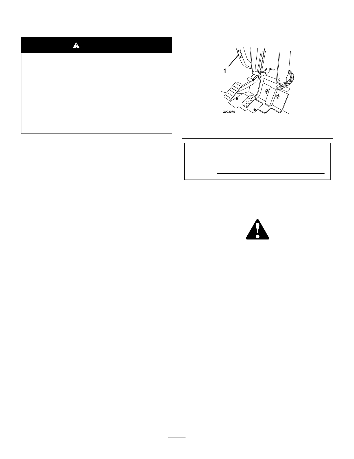
104-6581
1.Warning—readtheOperator'sManual.
2.Firehazard—beforefueling,stoptheengine.
3.Warning—donotoperatethismachineunlessyouaretrained.
4.Tippinghazard—usecautionanddriveslowlywhileonslopes;driveslowlywhenturning,keepthevehiclespeedunder16MPH
(26km/h)whencarryingafullorheavyloadandwhendrivingonroughterrain.
5.Fallingandarm/leginjuryhazards—donotcarrypassengersinthecargobedandkeeparmsandlegsinsideofthevehicleatall
times.
119-9727
1.Horn7.Powerpoint
2.Hourmeter
3.Headlights
4.Engine—stop10.Fallinghazard—donotcarrypassengersinthecargobed.
5.Engine—on11.Fallinghazard—donotallowchildrentooperatethevehicle.
6.Engine—start
120-0627
1.Cutting/dismembermenthazard,fan—stayawayfrom
movingparts,keepallguardsandshieldsinplace.
8.Warning—readtheOperator'sManual.
9.Collisionhazard—donotoperatethevehicleonpublicstreets,
roads,orhighways.
115-7739
1.Falling,crushinghazard,bystanders—noriderson
machine.
9
Page 10
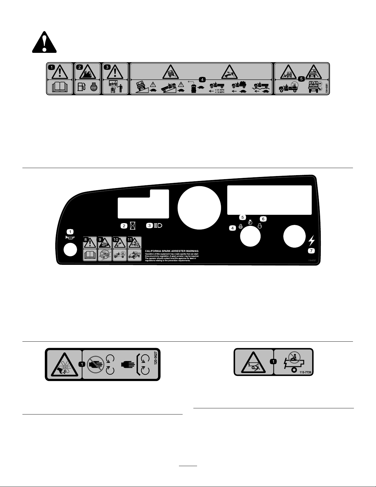
99-7345
1.Warning—readtheOperator'sManual.
2.Hotsurface/burnhazard—stayasafedistancefromthe
hotsurface.
3.Entanglementhazard,belt—stayawayfrommovingparts;
keepallguardsinplace.
4.Crushinghazard,cargobox—usetheproprodtosupport
thecargobed
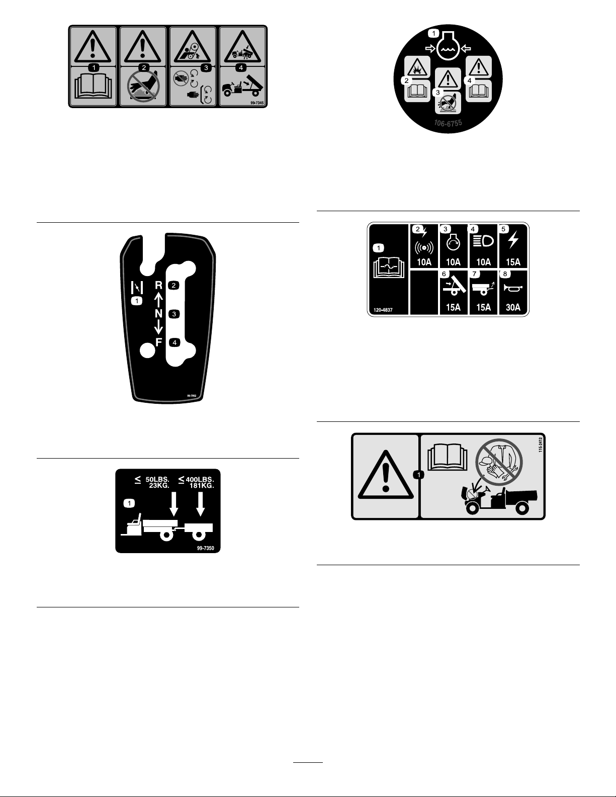
99-7952
106-6755
1.Enginecoolantunder
pressure.
2.Explosionhazard—read
theOperator'sManual.
3.Warning—donottouchthe
hotsurface.
4.Warning—readthe
Operator'sManual.
120-4837
1.ReadtheOperator's
Manualforinformationon
fuses.
2.Alarm/powerpoint,10A6.Lift,15A
3.Engine,10A
4.Headlights,10A8.Horn,30A
5.Machinefuse,15A
7.Rearlift,15A
1.Choke
2.Reverse4.Forward
3.Neutral
99-7350
1.Maximumtongueweightis50lb(23kg);maximumtrailer
weightis400lb(181kg).
115-2412
1.Warning—readtheOperator'sManual;nostorage.
10
Page 11

Setup
LooseParts
Usethechartbelowtoverifythatallpartshavebeenshipped.
ProcedureDescription
1
2
3
Note:Determinetheleftandrightsidesofthemachinefromthenormaloperatingposition.
Steeringwheel
Nopartsrequired
Operator'sManual
Engineowner’smanual1
PartsCatalog
SafetyTrainingmaterial
RegistrationCard
PredeliveryInspectionForm1
CerticateofQuality
Key2
Qty.
Use
1
–
1
1
1
1
1
Installthesteeringwheel(Model
07359TConly).
Checktheuidlevelsandtireair
pressure.
ReadtheOperator'sManualandview
thetrainingmaterialbeforeoperating
themachine.
11
Page 12
1
2
InstallingtheSteeringWheel
Partsneededforthisprocedure:
1
Steeringwheel
Procedure
Note:ThisprocedureisonlyneededforModel07359TC.
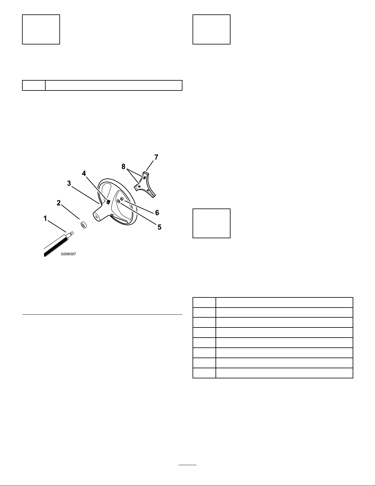
1.Throughtheopeningsinthebackofthesteering
wheel,releasethelocktabsofthecentercoverand
removethecoverfromthewheel(Figure3).
CheckingtheFluidLevelsand TireAirPressure
NoPartsRequired
Procedure
1.Checktheengineoillevelbeforeandaftertheengineis
rstoperated;refertoCheckingtheEngine-OilLevel
(page19).
2.Checkthebrakeuidlevelbeforetheengineisrst
operated;refertoCheckingtheBrakeFluidLevel(page
19).
3.Checkthetransaxle-oillevelbeforetheengineisrst
operated;refertoCheckingtheTransaxleOilLevel
(page38).
4.Checktheairpressureinthetires;refertoChecking
theTireAirPressure(page20)
Figure3
1.Steeringshaft
2.Dustcover6.Locknut
3.Steeringwheel7.Centercover
4.Tabslotsinwheel
2.Removethelocknutandwasherfromthesteering
shaft(Figure3).
3.Alignthesteeringwheelontothesplinesofthesteering
shaft(Figure3).
Note:Positionthesteeringwheelontheshaft
sothatwhenthetiresofthemachinearepointed
straightahead,thecrossbeamofthesteeringwheelis
horizontalandthethickerspokeofthesteeringwheel
ispointingdown.
4.Assemblethewasherandlocknutthreadsofthe
steeringshaft(Figure3).
5.Torquethenutto24-29N-m(18-22ft-lb).
6.Alignthelocktabsofthecentercovertotheopenings
inthesteeringwheelandpressthecoverintothewheel
untilthelockstabssnapintoplace(Figure3).
5.Washer
8.Opening(foraccesstothe
steeringwheeltabs)
3
ReadingtheManualand ViewingtheSafetyTraining Material
Partsneededforthisprocedure:
1
Operator'sManual
1Engineowner’smanual
1
PartsCatalog
1
SafetyTrainingmaterial
1
RegistrationCard
1PredeliveryInspectionForm
1
CerticateofQuality
2Key
Procedure
•ReadtheOperator'sManualandEngineowner'smanual.
•Viewthesafetytrainingmaterial.
•Fillouttheregistrationcard.
•CompletethePredeliveryInspectionForm.
•ReviewtheCerticateofQuality.
12
Page 13
ProductOverview
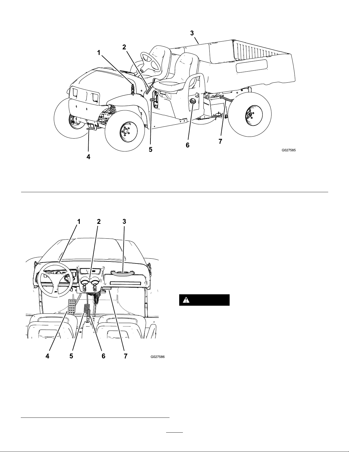
Figure4
1.Hoodlatch
2.Parkingbrakehandle4.Towingtongue6.Fuelcap
3.Cargobox5.Gearshiftselector7.Cargoboxlever
Controls
AcceleratorPedal
Usetheacceleratorpedal(Figure5)tovarygroundspeed
ofthemachine.Pressingdownthepedalincreasesground
speed.Releasingthepedalwillslowthemachine.
Note:Themaximumforwardspeedis26km/h(16mph).
BrakePedal
Usethebrakepedalisusedtostoporslowthemachine
(Figure5).
CAUTION
Operatingamachinewithwornorincorrectly
adjustedbrakescanmayresultinpersonalinjury.
Ifbrakepedaltravelstowithin25mm(1inch)of
thevehicleoorboard,thebrakesmustbeadjusted
orrepaired.
1.Steeringwheel
2.Cupholder
3.Passengerhandhold
4.Brakepedal
Figure5
5.Acceleratorpedal
6.Parkingbrakehandle
7.Operator'sManualstorage
ParkingBrakeLever
Theparkingbrakeleverislocatedbetweentheseats(Figure
4andFigure5).Whenevertheengineisshutoff,setthe
(centerconsole)
tube
parkingbraketopreventthemachinefromaccidentalmoving.
Tosettheparkingbrake,pullupontheparkingbrakelever.
Toreleasetheparkingbrake,pushtheleverdown.Ifthe
machineisparkedonasteepgrade,makesurethatthe
parkingbrakeisset.
13
Page 14
HornButton(TCModelonly)
Thehornbuttonislocatedatthelowerleftcornerofthedash
panel(Figure6).Pressthehornbuttontosoundthehorn.
oillightwarnstheoperatoriftheengineoilpressuredrops
belowasafeleveltooperatetheengine.Ifthelightcomeson
andremainslit,shutofftheengineandchecktheengineoil
level.Addoiltotheengineifnecessary;refertoCheckingthe
Engine-OilLevel(page19).
Note:Theoillightmayicker.Thisisnormalandnoaction
needstobetaken.
EngineCoolant-temperatureLight
Theenginecoolant-temperaturelightislocatedtothe
rightofthebatteryandtheengineoilpressurelights,and
abovetheglowplugindicatorlight(Figure6).Theengine
coolant-temperaturelightwarnstheoperatorthatthecoolant
temperatureoftheengineistoohottocontinueoperating
theengine(theengineisoverheating).Stoptheengineand
allowthemachinetocooldown.Checkthecoolantleveland
thebeltstothefanandwaterpump.Fillthecoolantreservoir
withcoolantasneededandreplaceanyworn,damaged,or
slippingbelts.
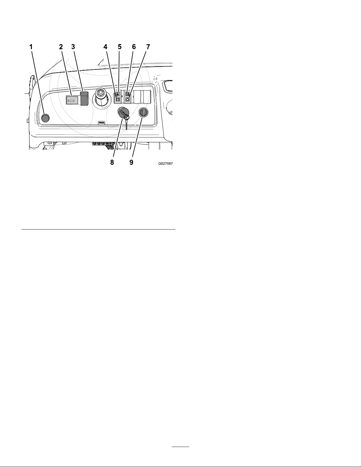
Figure6
1.Hornbutton(TCModels
Only)
2.Hourmeter
3.Lightswitch
4.Batterylight9.Powerpoint
5.Engineoilpressurelight
6.Engine
coolant-temperaturelight
7.Glow-plugIndicatorlight
8.Starterswitch
LightSwitch
Thelightswitchislocatedtotheleftofthesteeringcolumn
(Figure6).Usethelightswitchtoilluminatetheheadlights.
Pushupthelightswitchturnontheheadlightsorpushdown
theswitchtoturnoffthelights.
HourMeter
Thehourmeterislocatedtotheleftofthelightswitch
(Figure6).Usethehourmetertondoutthetotalnumberof
hourstheenginehasrun.Thehourmeterstartstofunction
wheneveryouturnthekeyswitchtotheOnpositionorif
theengineisrunning.
BatteryLight
Thebatterylightislocatedtotherightofthesteeringcolumn
andabovetheoillight(Figure6).Thebatterylightwillturn
onforseveralsecondswhenyourststarttheengine,and
thenturnoffoncetheengineisrunning.Ifthelightremains
onwhiletheengineisrunning,thealternator,battery,or
electricalsystemisdamaged.
EngineOilPressureLight
Important:Iftheengineoverheatingproblempersists,
contactyourAuthorizedT oroDealerfordiagnosticsand
repair.
Glow-plugIndicatorLight
Theglow-plugindicatorlightislocatedtotherightofthe
batteryandtheengineoilpressurelights,andbelowthe
enginecoolant-temperaturelight(Figure6).Theglow-plug
indicatorlightwillilluminateredwhenyourotatetheignition
switchtotheOnpositionandtheengineiscold.Thelight
indicatesthattheglowplugsareoperating.
StarterSwitch
Theignitionswitchislocatedtotherightofthesteering
columnandbelowtheindicatorlightsforthebattery,engine
oilpressure,enginecoolanttemperature,glowplugs(Figure
6).Usetheignitionswitchtostartandstoptheengine.The
switchhas3positions:Off,On,andStart.Rotatethekey
clockwisetotheOnpositiontoactivatetheglowplugs.
Whentheglowplugindicatorlightturnsoff,rotatethekey
counterclockwisetotheStartpositiontostarttheengine.
Toshutofftheengine,rotatethekeycounterclockwiseto
theOffposition.
Note:Removethekeyfromtheignitionwhenleavingthe
machine.
PowerPoint
Thepowerpointislocatedtotherightofthestarterswitch
(Figure6).Usethepowerpointtopower12voltoptional
electricalaccessories.
Theengineoilpressurelightislocatedtotherightofthe
steeringcolumnandbelowthebatterylight(Figure6).The
14
Page 15
Gear-ShiftSelector
G009193
1
2
PassengerHandHolds
Thegearshiftselectorislocatedbetweentheseatsandbelow
theparkingbrakelever.Thegearshiftselectorhasthree
positions:Forward,Reverse,andNeutral(Figure7).
Note:Theenginewillstartandruninanyofthethree
positions.
Important:Alwaysstopthevehiclebeforechanging
gears.
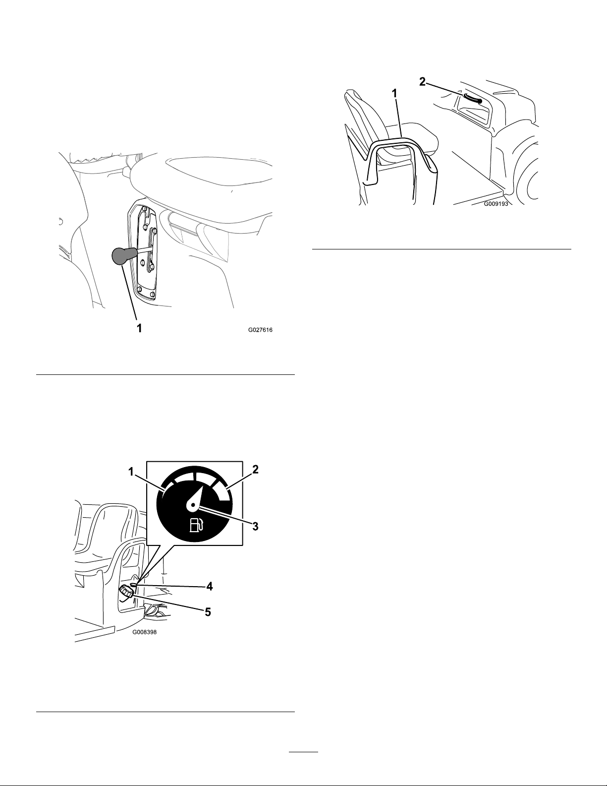
Thepassengerhandholdsarelocatedontherightsideofthe
dashpanelandattheoutsideofeachseat(Figure9).
Figure9
1.Handhold—hiprestraint2.Passengerhandhold
Figure7
1.Gearshiftselector
FuelGauge
Thefuelgauge(Figure8)islocatedonthefueltank,nextto
thellercapattheoperator'ssideofthemachine.Thegauge
displaystheamountoffuelinthetank.
Figure8
1.Empty4.Fuelgauge
2.Full5.Fuel-tankcap
3.Needle
15
Page 16

Specications
Note:Specicationsanddesignaresubjecttochangewithoutnotice.
Baseweight
Ratedcapacity(onlevelground)749kg(1650lb)total,including90.7kg(200lb)operatorand90.7kg(200lb)passenger,load,
Maximumgrossvehicleweight
(GVW)(onlevelground)
Maximumcargocapacity(onlevel
ground)
Towcapacity:
StandardhitchTongueweight23kg(50lb)Maximumtrailerweight182kg(400lb)
Heavy-dutyhitch
Overallwidth150cm(59inches)
Overalllength299cm(117.75inches)
Groundclearance25.4cm(10inches)atthefrontwithnoloadoroperator,18cm(7inches)attherearwith
Wheelbase
Wheeltread(centerlinetocenter
line)
Cargoboxlength116.8cm(46inches)inside,132.7cm(52-1/4inches)outside
Cargoboxwidth124.5cm(49inches)inside,150cm(59inches)atoutsideofthemoldedfenders
Cargoboxheight25.4cm(10inches)inside
Maximumspeed
Enginespeed(non-adjustable)
Dry590kg(1300lb)
trailertongueweight,grosstrailerweight,accessories,andattachments
1341kg(2950lb)total,includingalloftheweightslistedabove
567kg(1250lb)total,includingtrailertongueweightandgrosstrailerweight
Tongueweight45kg(100lb)Maximumtrailerweight363kg(800lb)
noloadoroperator
205.7cm(81inches)
124.5cm(49inches)inthefront,120cm(47-1/4inches)intherear
26km/h(16mph)
Lowidle–1250±50rpm,Highidle–3470±50rpm
Attachments/Accessories
AselectionofToroapprovedattachmentsandaccessoriesisavailableforusewiththemachinetoenhanceandexpand
itscapabilities.ContactyourAuthorizedServiceDealerorDistributororgotowww.Toro.comforalistofallapproved
attachmentsandaccessories.
16
Page 17

Operation
g014860
1
2
3
Note:Determinetheleftandrightsidesofthemachine
fromthenormaloperatingposition.
ThinkSafetyFirst
Pleasecarefullyreadallofthesafetyinstructionsanddecals
inthesafetysection.Knowingthisinformationcouldhelp
youorbystandersavoidinjury.
OperatingtheCargoBox
RaisingtheCargoBox
WARNING
Drivingthemachinewiththecargoboxraisedmay
causethemachinetotiporrolleasier.Thebox
structuremaybecomedamagedifyouoperatethe
machinewiththeboxraised.
•Onlyoperatethemachinewhenthecargobox
isdown.
•Afteremptyingthecargobox,lowerit.
CAUTION
Ifaloadisconcentratednearthebackofthecargo
boxwhenyoureleasethelatches,theboxmay
unexpectedlytipopeninjuringyouorbystanders.
•Centerloadsinthecargoboxifpossible.
•Holdthecargoboxdownandensurethatno
oneisleaningovertheboxorstandingbehindit
whenreleasingthelatches.
Figure10
1.Latchlever3.Detentslot
2.Proprod
LoweringtheCargoBox
WARNING
Theweightoftheboxmaybeheavy.Handsor
otherbodypartscouldbecrushed.
Keephandsandotherbodypartsclearwhen
loweringthebox.
1.Raisethecargoboxslightlybyliftinguponthelatch
lever(Figure10).
2.Pulltheproprodoutofthedetentslot(Figure10).
3.Lowertheboxuntilitlatchesintosecurely(Figure10).
•Removeallcargofromtheboxbeforeliftingthe
boxuptoservicethemachine.
1.Liftthelatchleverthatisattheeithersidenearthe
forwardcornerofthecargobox,andlifttheboxup
(Figure10).
2.Securethecargoboxbypullingtheproprodintothe
reardetentatendoftheslotthatisintheleftframeof
themachine(Figure10).
17
Page 18

OpeningtheTailgate
1.Ensurethatthecargoboxisdownandlatched.
2.Liftuponthengerpullsatthebackpanelofthetail
gate(Figure11).
Figure11
1.Tailgateange(cargobox)3.Liftup(ngerpull)
2.Lockange(tailgate)
4.Rotaterearwardanddown
Figure12
3.Useashort,shakingmotiontorotatethetailgateback
andforthseveraltimes(Figure12).
Note:Thisactionwillhelpmovematerialawayfrom
thehingearea
4.Lowerthetailgateandcheckformaterialremainingin
thehingearea.
5.Repeatsteps1through4untilthematerialisremoved
fromthehingearea.
6.Rotatethetailgateupandforwarduntilthelockanges
ofthetailgateareushwiththetailgatepocketinthe
cargobox(Figure11).
Note:Raiseorlowerthetailgateinordertoalignthe
lockangesofthetailgatewiththeverticalopenings
betweenthetailgateangesofthecargobox.
3.Alignthelockangesofthetailgatewiththeopenings
betweenthetailgateangesofthecargobox(Figure
11).
4.Rotatethetailgaterearwardanddown(Figure11).
ClosingtheTailgate
Ifyouunloadedloosematerialsuchassand,landscapingrock,
orwoodchipsfromthecargoboxofthemachine,somethe
materialthatyouunloadedmayhavelodgedinthehinge
areaofthetailgate.Performthefollowingbeforeclosingthe
tailgate.
1.Useyourhandstoremoveasmuchofthematerial
fromthehingeareaaspossible.
2.Rotatethetailgatetoapproximately45°position
(Figure12).
7.Lowerthetailgateuntilitisseatedinthebackofthe
cargobox(Figure11).
Note:Thelockangesofthetailgatewillbefully
securedbythetailgateangesofthecargobox.
PreformingPre-Starting Checks
ServiceInterval:BeforeeachuseordailyCheckthe
followingitemseachtimeyoubegin
usingthemachinefortheday:
•Checkbrakeuidlevels,andaddthespeciedbrake
uidsasneeded;refertoCheckingtheBrakeFluidLevel
(page19).
•Checkengineoil,andaddthespeciedoilasneeded;
refertoCheckingtheEngine-OilLevel(page19).
•Checktheairpressureinthetires;refertoCheckingthe
TireAirPressure(page20).
•Checkthebrakepedaloperation.
•Checktoseethatthelightsareworking.
•Turnthesteeringwheeltotheleftandrighttocheck
steeringresponse.
•Checkforoilleaks,looseparts,andanyothernoticeable
malfunctions.
18
Page 19

Note:Shutofftheengineandallowallmovingpartsto
F
-30
C
-34
-10
-23
10
-12
32
0
50
10
70
21
90
32
110
43
STARTING TEMPERA TURE RANGE ANTICIPATED BEFORE NEXT OIL CHANGE
*A synthetic 5W -30 oil may be used.
15W -40
10W -30
5W-30
G017503
stopbeforecheckingforoilleaks,looseparts,andother
wearanddamage.
Ifanyoftheaboveitemsarenotcorrect,notifyyour
mechanicorcheckwithyoursupervisorbeforetakingthe
machineoutfortheday.Yoursupervisormaywantyouto
checkotheritemsonadailybasis,soaskhimorherabout
additionaloperator’ sresponsibilities.
CheckingtheBrakeFluid Level
ServiceInterval:BeforeeachuseordailyCheckthe
brake-uidlevelbeforethemotorisrst
used.
BrakeFluidType:DOT3
1.Parkthemachineonalevelsurface,settheparking
brake,rotatetheOn/OffswitchtotheOffposition,
andremovethekey..
2.Removetherubberpluginthecenterandontopof
thedashtogainaccesstothemasterbrakecylinder
andreservoir(Figure13).
Figure14
1.Brake-uidreservoir
2.Minimumline
4.Iftheuidlevelislow,preformthefollowing:
A.Cleantheareaaroundthereservoircap,and
removethecap(Figure13).
B.AddDOT3brakeuidtothereservoiruntilthe
uidlevelisabovetheMinimumline(Figure14).
Note:Donotoverllthereservoirwithbrake
uid.
C.Installthereservoircap(Figure13).
5.Installtherubberplugintopofthedash(Figure14).
CheckingtheEngine-OilLevel
ServiceInterval:BeforeeachuseordailyChecktheoillevel
intheenginebeforetheengineisrst
started.
Note:Themachineisshippedwithoilinthecrankcase;
however,checktheoilbeforeandafteryoustarttheengine.
Figure13
1.Rubberplug
2.Reservoircap
3.Fillerneck(reservoir)
4.DOT3brakeuid
3.Lookattheoutlineoftheuidlevelatthesideofthe
reservoir.(Figure14).
Note:ThelevelshouldbeabovetheMinimumline
OilType:Detergentoil(APIserviceCH-4,CI-4,CJ-4,or
higher)
Viscosity:Seethetablebelow
Figure15
1.Movethemachinetoalevelsurface.
2.Raisethecargobox;refertoRaisingtheCargoBox
(page17).
3.Usearagtocleanaroundtheoildipstick(Figure16)so
thatdirtcannotfallintothedipsticktubeanddamage
theengine.
19
Page 20

G016858
1
2
2.Ifneeded,adjusttheairpressureinthetiresbyadding
orremovingairinthetires.
AddingFuel
Theenginerunsonclean,freshdieselfuelwithaminimum
cetaneratingof40.Purchasefuelinquantitiesthatcanbe
usedwithin30daystoensurefuelfreshness.
Usesummergradedieselfuel(No.2-D)attemperatures
above20F(–7C)andwintergradedieselfuel(No.1-D
orNo.1-D/2-Dblend)below20F(–7C).Useofwinter
gradedieselfuelatlowertemperaturesprovideslowerash
pointandpourpointcharacteristics,allowingeasierstartsand
lesseningthechancesofchemicalseparationofthefueldue
tolowertemperatures.
Useofsummergradedieselfuelabove20F(–7C)will
contributetowardlongerlifeofthefuelpumpcomponents.
Figure16
1.Fillcap
4.Removetheoildipstickandwipetheendclean.
5.Slidetheoildipstickintothedipsticktubefullyseating
it(Figure16).
6.Pullthedipstickoutandlookattheend(Figure16).
Note:Iftheoillevelislow,removethellercapfrom
theengineandaddthespeciedoiltoraisethelevelup
to,butnotover,theFullmarkonthedipstick.Addthe
oilslowlyandchecktheleveloftenduringthisprocess.
Donotoverlltheenginewithoil..
7.Installtheoildipstickandrmlyseatit(Figure16).
8.Lowerthecargobox;refertoLoweringtheCargoBox
(page17).
2.Oildipstick
CheckingtheTireAirPressure
ServiceInterval:Beforeeachuseordaily
TireAirPressureRange:55to103kPa(8to22psi)
Important:Donotexceedthemaximumairpressure
indicatedonthesidewallofthetire.
Note:Theairpressureneededinthetiresisdeterminedby
thepayloadthatyouintendtocarry.
1.Checktheairpressureinthetires.
Important:Neverusekeroseneorgasolineinplaceof
dieselfuel.Failuretoobservethiscautionwilldamage
theengine.
DANGER
Incertainconditions,fuelisextremelyammable
andhighlyexplosive.Areorexplosionfromfuel
canburnyouandothersandcandamageproperty.
•Fillthefueltankoutdoors,inanopenarea,when
theengineiscold.Wipeupanyfuelthatspills.
•Neverllthefueltankinsideanenclosedtrailer.
•Donotllthefueltankcompletelyfull.Addfuel
tothefueltankuntilthelevelis1inch(25mm)
belowthebottomofthellerneck.Thisempty
spaceinthetankallowsfueltoexpand.
•Neversmokewhenhandlingfuel,andstayaway
fromanopenameorwherefuelfumesmaybe
ignitedbyaspark.
•Storefuelinanapprovedcontainerandkeepit
outofthereachofchildren.Neverbuymore
thana30-daysupplyoffuel.
•Donotoperatethemachinewithouttheentire
intakeandexhaustsysteminplaceandinproper
workingcondition.
Note:Theairpressurerangeinthefrontandreartires
is55to103kPa(8to22psi).
•Uselowerairpressureinthetiresforlighter
payloads,forlessthesoilcompaction,fora
smoothertheride,andtominimizetiremarksin
theground.
•Usehigherairpressureinthetiresforcarrying
heavierpayloadsathigherspeeds.
20
Page 21

DANGER
Incertainconditionsduringfueling,static
electricitycanbereleasedcausingasparkwhich
canignitethefuelvapors.Areorexplosionfrom
fuelcanburnyouandothersandcandamage
property.
•Alwaysplacefuelcontainersonthegroundaway
fromyourvehiclebeforelling.
•Donotllfuelcontainersinsideavehicleoron
atruckortrailerbedbecauseinteriorcarpets
orplastictruckbedlinersmayinsulatethe
containerandslowthelossofanystaticcharge.
•Whenpractical,removefuel-poweredequipment
fromthetruckortrailerandrefueltheequipment
withitswheelsontheground.
•Ifthisisnotpossible,thenrefuelsuchequipment
onatruckortrailerfromaportablecontainer,
ratherthanfromafueldispensernozzle.
•Ifafueldispensernozzlemustbeused,keepthe
nozzleincontactwiththerimofthefueltank
orcontaineropeningatalltimesuntilfuelingis
complete.
FillingtheFuelTank
Thefueltankcapacityisapproximately26.5L(7USgallons).
1.Shutofftheengineandsettheparkingbrake.
2.Cleantheareaaroundthefuel-tankcap(Figure17).
Note:Thisspaceinthetankallowsfueltoexpand.
Donotoverllthefueltank..
5.Installthefueltankcapsecurely.
6.Wipeupanyfuelthatmayhavespilled.
StartingtheEngine
Important:Donotattempttopushortowthevehicle
togetitstarted.
1.Sitintheoperator'sseat,insertthekeyintothestarter
switch,pressdownonthebrake,androtatethekey
clockwisetotheOnposition.
Note:Ifthebackupalarmisinstalledandthegear
shiftselectorisinReverse,thebuzzerwillsoundto
warntheoperator.
2.Oncetheglowplugindicatorlightturnsoff,rotatethe
keycounterclockwisetotheStartposition.
3.Releasetheparkingbrake.
StoppingtheMachine
Important:Whenstoppingthemachineonanincline,
usetheservicebrakestostopthemachineandsetthe
parkingbraketoholdthemachineinplace.Usingthe
acceleratortostallthemachineonthehillcandamage
themachine.
1.Removeyourfootfromtheacceleratorpedal;referto
AcceleratorPedal(page13)).
2.Slowlypressthebrakepedaltoapplytheservicebrakes
untilthemachinecomestoacompletestop;referto
BrakePedal(page13).
Figure17
1.Empty4.Fuelgauge
2.Full5.Fuel-tankcap
3.Needle
3.Removethefuel-tankcap.
4.Fillthetanktoabout25mm(1inch)belowthetopof
tank,(bottomofthellerneck).
Note:Thestoppingdistancemayvarydependingon
themachineloadandspeed.
ParkingtheMachine
1.Stopthemachineusingtheservicebrakesbypressing
andholdingthebrakepedal;refertoBrakePedal(page
13).
2.Settheparkingbrakebypullinguptheparking-brake
lever;refertoParkingBrakeLever(page13).
3.Rotatethekeyforthestarterswitchcounterclockwise
totheOffposition;refertoStarterSwitch(page14).
4.Removethekeyfromthestarterswitch.
21
Page 22

BreakinginaNewMachine
ServiceInterval:Aftertherst100hours—Performthe
breakinginanewmachineguidelines.
Performthebreakinginanewmachineguidelinestoprovide
properperformanceandlonglifeforthemachine.
•Checktheuidandengineoillevelsregularly.Remain
alertforsignsthatthemachineoritscomponentsare
overheating.
•Afterstartingacoldengine,letitwarmupforabout15
secondsbeforeusingthemachine.
•Avoidhardbrakingsituationsfortherstseveralhoursof
newmachinebreak-inoperation.Newbrakeliningsmay
notbeatoptimumperformanceuntilseveralhoursofuse
hascausedthebrakestobecomeburnished(broken-in).
•Varythemachinespeedduringoperation.Avoidfast
startsandquickstops.
•Abreak-inoilforengineisnotrequired.Originalengine
oilisthesametypespeciedforregularoilchanges.
•RefertoMaintainingtheVehicleunderSpecialOperating
Conditions(page26)foranyspeciallowhourchecks.
•Checkthefrontsuspensionpositioningandadjustitif
necessary;refertoAdjustingtheFrontWheelT oe-inand
Camber(page37).
LoadingtheCargoBox
Usethefollowingguidelineswhenloadingthecargoboxand
operatingthemachine:
•Observetheweightcapacityofthemachineandlimit
theweightoftheloadthatyoucarryinthecargoboxas
describedinSpecications(page16)andonthegross
vehicleweighttagofthemachine(Figure18).
Note:Note:Theloadratingisspeciedformachine
operationonalevelsurfaceonly .
•Reducetheweightoftheloadthatyoucarrywhenthe
materialsaretall(andhaveahighcenterofgravity)such
asastackofbricks,landscapingtimbers,orfertilizerbags.
Distributetheloadaslowaspossible,makingsurethat
theloaddoesnotreduceyourabilitytoseebehindthe
machinewhenoperatingit.
•Keeploadscenteredbyloadingthecargoboxasfollows:
–Evenlypositiontheweightinthecargoboxfrom
sidetoside.
Important:Tippingoverismorelikelytooccur
ifthecargoboxisloadedtooneside.
–Evenlypositiontheweightinthecargoboxfrom
fronttoback.
Important:Lossofsteeringcontrolorthe
machinemaytipoverifyoupositiontheload
behindtherearaxleandthetractiononthefront
tiresisreduced.
•Useextracautionwhentransportingoversizedloadsin
thecargobox,particularlywhenyoucannotcenterthe
wightoftheoversizeloadtothecargobox
•Wheneverpossible,securetheloadbybindingittothe
cargoboxsoitdoesnotshift.
•Whentransportingliquidinalargetank(suchasasprayer
tank),usecautionwhendrivingthemachineuphillor
downhill,whensuddenlychangingspeedorstopping,or
whendrivingovertoughsurfaces.
Thecapacityofthecargoboxis0.37m
(volume)ofmaterialthatcanbeplacedintheboxwithout
exceedingthevehicleloadratingscanvarygreatlydepending
onthedensityofthematerial.Forexample,alevelboxofwet
sandweighs680kg(1500lb),whichexceedstheloadrating
by113kg(250lb).Butalevelboxofwoodweighs295kg
(650lb),whichisundertheloadrating.
Seethetablebelowforloadvolumelimitswithvarious
materials:
3
(13ft3).Theamount
Figure18
1.Grossmachineweightdecal
•Reducetheweightoftheloadthatyoucarryinthecargo
boxwhenoperatingthemachineonhillsandrough
terrain.
MaterialDensityMax.cargobox
Gravel,dry1521.7kg/m
Gravel,wet1922.2kg/m
Sand,dry1441.6kg/m
Sand,wet1922.2kg/m
Wood
Bark
Earth,packed
22
<720.8kg/m
720.8kg/m
1601.8kg/m
capacity(onlevel
ground)
3
(95lb/ft
(120lb/ft
(90lb/ft
(120lb/ft
(100lb/ft
3
)
3
)
3
)
3
)
3
(45
3
lb/ft
)
3
(<45
3
lb/ft
)
3
)
3/4full(approx.)
3
1/2full(approx.)
3
3
3
3/4full
1/2full
Full
Full
3/4full(approx.)
Page 23

TransportingtheVehicle
TowingtheMachine
Formovingthevehiclelongdistances,atrailershouldbe
used.Makesurethatthevehicleissecuredtothetrailer.Refer
toFigure19andFigure20forthelocationofthetie-down
points.
CAUTION
Looseseatsmayfalloffofthevehicleandtrailer
whentransportingandlandonanothervehicleor
becomeanobstructionontheroad.
Removetheseatsormakesurethattheseatsare
securelyfastenedinthedetents.
Figure19
1.Towingtongueandtiedownpoint(frontofthemachine)
Incaseofanemergency ,themachinecanbetowedfora
shortdistance.However,wedonotrecommendthisasa
standardoperatingprocedure.
WARNING
Towingatexcessivespeedscouldcausealossof
steeringcontrol,resultinginpersonalinjury.
Nevertowthemachinefasterthan8km/h(5mph).
Towingthemachineisa2-personjob.Ifthemachinemust
bemovedaconsiderabledistance,transportitonatruckor
trailer;refertoTransportingtheVehicle(page23).
1.Removethedrivebeltfromthemachine;referto
ReplacingtheDriveBelt(page44).
2.Afxatowlinetothetongueatthefrontofthe
machine’sframe(Figure19).
3.Putthetransmissionofthemachineinneutraland
releasetheparkingbrake;refertoGear-ShiftSelector
(page15)andParkingBrakeLever(page13).
TowingaTrailer
Figure20
1.Rearaxletie-downpoints(backofthemachine)
Themachineiscapableofpullingtrailers.2typesoftow
hitchesareavailableforthemachine,dependingonyour
application.ContactyourAuthorizedToroDistributorfor
details.
Whenhaulingcargoortowingatrailer,donotoverloadyour
vehicleortrailer.Overloadingcancausepoorperformance
ordamagetothebrakes,axle,engine,transaxle,steering,
suspension,bodystructure,ortires.Alwaysloadatrailerwith
60%ofthecargoweightinthefrontofthetrailer.Thisplaces
approximately10%oftheGrossTrailerWeight(GTW)on
thetowhitchofthevehicle.
Themaximumcargoloadshallnotexceed567kg(1250lb),
includingtheGTW.Forexample,iftheGTW=181.5kg
(400lb)thenthemaximumcargoload=386kg(850lb)
Toprovideadequatebrakingandtraction,alwaysloadthe
cargoboxwhentrailering.DonotexceedtheGTWorGVW
limits.
Avoidparkingavehiclewithatraileronahill.Ifyoumust
parkonahill,engagetheparkingbrakeandblockthetrailer
tires.
23
Page 24

Maintenance
Note:LookingforanElectricalSchematicorHydraulicSchematicforyourmachine?Downloadafreecopyoftheschematicby
visitingwww .T oro.comandsearchingforyourmachinefromtheManualslinkonthehomepage.
Note:Determinetheleftandrightsidesofthemachinefromthenormaloperatingposition.
RecommendedMaintenanceSchedule(s)
MaintenanceService
Interval
Aftertherst8hours
Aftertherst50hours
Aftertherst100hours
Beforeeachuseordaily
Every100hours
MaintenanceProcedure
•Checktheconditionofthedrivebelt.
•Changetheengineoil.
•Performthebreakinginanewmachineguidelines.
•Preformthepre-staringchecks.Checkthefollowingitemseachtimeyoubegin
usingthemachinefortheday:
•Checkthebrake-uidlevel.
•Checktheengineoil.Checktheoillevelintheenginebeforetheengineisrst
started.
•Checkthetirepressure.
•Checkgearshiftoperation.
•Inspecttheprimarydriveclutch.
•Checktheradiatorcoolantlevel.
•Greasethebearingsandbushings.
•Air-cleanerlter:Inspectafterevery100operatinghoursReplacetheairlter
elementsoonerifitdirtyordamaged.
•Checktheconditionofthetiresandrims.
•T orquethewheel-lugnuts.
•Checkthefrontwheeltoe-inandcamber.
•Checkthetransaxleoillevel.
•ChecktheoperationoftheNeutralgearshiftposition.
•Cleantheenginecoolingareas(twiceasofteninspecialoperatingconditions;refer
toMaintainingtheVehicleunderSpecialOperatingConditions).
•Inspectthebrakes.
Every150hours
Every200hours
Every300hours
Every400hours
Every800hours
Every1,000hours
Yearly
Important:Refertoyour
•Changetheengineoil(twiceasofteninspecialoperatingconditions;referto
MaintainingtheVehicleunderSpecialOperatingConditions).
•Changetheoillter.Changetheoiltwiceasoftenduringspecialoperating
conditions;refertoMaintainingtheVehicleunderSpecialOperatingConditions.
•Replacetheairlterelement.
•Cleantheprimarydriveclutch(moreoftenindustyormuddyconditions).
•Adjusttheparkingbrakeifneeded.
•Checktheconditionandtensionofthedrivebelt.
•Greasethefrontwheelbearings.
•Inspectthefuellinesandconnections.
•Replacethefuellter.
•Changethetransaxleuid.
•Changetheradiatorcoolant.
•Changethebrakeuid.
•Completeallyearlymaintenanceproceduresspeciedintheengineowner'smanual.
engine operator's man ual
foradditionalmaintenanceprocedures.
24
Page 25

DailyMaintenanceChecklist
Duplicatethispageforroutineuse.
Fortheweekof: MaintenanceCheckItem
Mon.Tues.Wed.Thurs.Fri.
Checkbrakeandparking
brakeoperation.
Checkgearshift/neutral
operation.
Checkfuellevel.
Checkengineoillevel.
Checktransaxleoillevel.
Inspectairlter .
Inspectenginecooling
ns.
Checkunusualengine
noises.
Checkunusualoperating
noises.
Checkclutchoperation.
Checktirepressure.
Checkuidleaks.
Checkinstrument
operation.
Checkaccelerator
operation.
Lubricateallgrease
ttings.
Touchupdamagedpaint.
Sat.Sun.
WARNING
Thebedmustberaisedtoperformsomeroutinemaintenance.
Araisedbedcanfallandinjurepersonsthatareunderneathit.
•Alwaysusetheproprodtoholdthebedupbeforeworkingunderit.
•Removeanyloadmaterialfromthebedbeforeworkingunderit.
CAUTION
Ifyouleavethekeyinthestarterswitch,someonecouldaccidentlystarttheengineandseriouslyinjure
youorotherbystanders.
Removethekeyfromthestarterswitchbeforeyoudoanymaintenance.
25
Page 26

Premaintenance
Procedures
MaintainingtheVehicleunder SpecialOperatingConditions
Ifthevehicleissubjectedtoanyoftheconditionslisted
below,maintenanceshouldbeperformedtwiceasfrequently.
•Desertoperation
•Coldclimateoperation(below50°F[10degreesC])
•Trailertowing
•Drivingtimetypicallylessthan5minutes
•Frequentoperationindustyconditions
•Constructionwork
•Afterextendedoperationinmud,sand,water,orsimilar
dirtyconditions,haveyourbrakesinspectedandcleaned
assoonaspossible.Thiswillpreventanyabrasive
materialfromcausingexcessivewear.
•Underfrequentheavydutyoperatingconditions,lubricate
allgreasettingsandinspectaircleanerdailytoprevent
excessivewear.
LiftingtheMachine
DANGER
Themachinemaybeunstablewhenusingajack.It
couldslipoffthejack,injuringanyonebeneathit.
•Donotstarttheenginewhilethemachineis
onajack.
Figure21
1.Frontliftingpoint
•Theliftingpointattherearofthemachineisunderthe
axletubes(Figure22).
Figure22
1.Rearliftingpoints
AccessingtheHood
Raisingthehood
1.Liftupthehandleoftherubberlatchesateachside
ofthehood(Figure23).
•Alwaysremovethekeyfromthestarterswitch
beforegettingoffofthemachine.
•Blockthetireswhenthemachineissupported
byliftingequipment.
•Usejackstandstosupportthemachineonce
youhaveliftedtheit.
Important:Whenevertheengineisrunforroutine
maintenanceand/orenginediagnostics,therearwheels
ofthemachineshouldbe25mm(1inch)offtheground,
withtherearaxlesupportedonjackstands.
•Theliftingpointatthefrontofthemachineisatthefront
oftheframebehindthetowingtongue(Figure21).
Figure23
2.Raisethehood.
26
Page 27

ClosingtheHood
1.Gentlylowerthehoodontothechassis.
Lubrication
2.Securethehoodbyaligningtherubberlatchesontothe
latchanchorsateachsideofthehood(Figure23).
GreasingtheMachine
ServiceInterval:Every100hours/Yearly(whichevercomes
rst)—Greasethebearingsandbushings.
Greasethemachinemorefrequently
whenusingitforheavy-dutyoperations.
GreaseType:Number2general-purpose,lithium-base
grease
1.Usearagtowipethegreasettingcleansothatforeign
mattercannotbeforcedintothebearingorbushing.
2.Withagreasegun,apply1or2pumpsofgreaseinto
thegreasettingsonthemachine.
3.Wipetheexcessgreaseoffthemachine.
Thegreasettingsarelocatedatthe4tie-rodends(Figure
24)andthe2kingpins(Figure25).
1.Greasetting
1.Greasetting(kingpin)
Figure24
Leftsideshown
2.Tierod
Figure25
Leftsideshown
27
Page 28

GreasingtheFrontWheel Bearings
ServiceInterval:Every300hours
Greasespecication:MobilgreaseXHP™-222
RemovingtheHubandRotor
1.Liftthefrontofthemachineandsupportitwithjack
stands.
2.Removethe5lugnutsthatsecurethewheeltothehub
(Figure26).
Figure27
Figure26
1.Lugnut3.Hub
2.Wheel
3.Removetheange-headbolts(3/8x1inch)thatsecure
thebracketforthebrakeassemblytothespindleand
separatethebrakefromthespindle(Figure27).
Note:Supportthebrakeassemblybeforeproceeding
tothenextstep.
1.Caliperbracket(brake
assembly)
2.Spindle
3.Flange-headbolts(3/8x
1inch)
4.Removethedustcapfromthehub(Figure28).
Figure28
1.Dustcap4.Tabwasher
2.Nutretainer
3.Spindlenut6.Cotterpin
5.Spindle
5.Removethecotterpinandhutretainerfromthe
spindleandspindlenut(Figure28).
6.Removethespindlenutfromthespindle,andseparate
thehubandrotorassemblyfromthespindle(Figure
28andFigure29).
28
Page 29

Figure29
8.Fillthecavityofhub50to80%fullofthespecied
grease(Figure30).
9.Assembletheinboardbearingontotheraceatthe
inboardsideofthehubandinstalltheseal(Figure30).
10.Repeatsteps1through9tothebearingsfortheother
hub.
InstallingtheHubandRotor
1.Applyalightcoatofthespeciedgreasetothespindle
(Figure31).
1.Hubandrotorassembly
2.Spindle
7.Wipecleanthespindlewitharag.
8.Repeatsteps1through7tothehubandrotoratthe
othersideofthemachine.
GreasingtheWheelBearings
1.Removetheoutboardbearingandbearingracefrom
thehub(Figure30).
Figure30
1.Outboardbearing
2.Outboard-bearingrace
3.Bearingcavity(hub)6.Seal
4.Inboard-bearingrace
5.Inboardbearing
Figure31
1.Retainer5.Hub,rotor,innerbearing,
2.Spindlenut6.Spindle
3.Tabwasher
4.Outerbearing
race,andseal
7.Holes(brakemountofthe
spindleframe)
2.Assemblethehubandrotorontothespindlewiththe
rotorinboard(Figure31).
3.Assembletheoutboardbearingontothespindleand
seatthebearingtotheoutboardrace(Figure31).
2.Removetheseal,inboardbearingandbearingrace
fromthehub(Figure30).
3.Wipecleanthesealandcheckforwearanddamage.
Note:Donotusecleaningsolventtocleantheseal.
Replacethesealifitiswornordamaged.
4.Cleanthebearingsandraces,andcheckthesepartsfor
wearanddamage.
Note:Replaceallwornordamagedparts.Ensurethat
thebearingsandracesarecleananddry.
5.Cleanthecavityofthehubofallgrease,dirt,anddebris
(Figure30).
6.Packthebearingswiththespeciedgrease.
7.Installtheinboardandoutboardbearingracesintothe
hub(Figure30).
Note:Ensurethattheracesarefullyseatedinthe
boresofthehub.
4.Assemblethetabwasherontothespindle(Figure31).
5.Threadthespindlenutontothespindleandtightenthe
nutwhilerotatingthehub(Figure31).
Note:Tightenthenutandrotatethespindleuntilthe
bearingsarefullyseatedandthehubhasnolinear-end
movement.
6.Loosenthespindlenutuntilthehubrotatesfreely.
7.Torquethespindlenutto170N-cm(15in-lb)while
rotatingthehub.
8.Installtheretaineroverthenutandcheckthealignment
oftheslotintheretainerandtheholeinthespindlefor
thecotterpin(Figure32).
Note:Iftheslotintheretainerandtheholeinthe
spindlearenotaligned,tightenthespindlenuttoalign
theslotandholetoamaximumtorqueof226N-cm
(20in-lb)onthenut.
29
Page 30

1.Dustcap
2.Nutretainer
Figure32
3.Cotterpin
EngineMaintenance
ServicingtheAirCleaner
ServiceInterval:Every100hoursReplacetheairlter
elementsoonerifitdirtyordamaged.
Every200hours
Note:Servicetheaircleanermorefrequently(everyfew
hours)ifoperatingconditionsareextremelydustyorsandy.
CheckingtheFilter
1.Raisethecargoboxandsecureitwiththeproprod;
refertoRaisingtheCargoBox(page17).
9.Installthecotterpinandbendeachlegsaroundthe
retainer(Figure32).
10.Installthedustcapontothehub(Figure32).
11.Repeatsteps1through10forthehubandrotoratthe
othersideofthemachine.
InstallingtheBrakesandWheels
1.Cleanthe2ange-headbolts(3/8x1inch)andapply
acoatforanti-seizecompoundtothethreadsofthe
bolts.
2.Alignthebrakepadstoeithersideoftherotor(Figure
27)andtheholesinthecaliperbracketwiththeholes
inthebrakemountofthespindleframe(Figure31).
3.Assemblecaliperbrackettothespindleframe(Figure
27)withthe2ange-headbolts(3/8x1inch),and
torquethebolts47to54N-cm(35to40ft-lb).
4.Aligntheholesinthewheeltothestudsofthehub
andassemblethewheeltothehubwiththevalvestem
outward(Figure26).
Note:Ensurethemountingsurfaceofthewheelis
ushwiththehub.
5.Securethewheeltothehubwiththelugnuts(Figure
26),andtorquethenutsto108to122N-m(80to90
ft-lb).
6.Repeatsteps1through5forthebrakeandwheelatthe
othersideofthemachine.
2.Checktheaircleanerbodyfordamagewhichcould
possiblycauseanairleak.Ensuretheair-ltercoveris
sealingaroundtheaircleanerhousing(Figure33).
Note:Replaceadamagedaircleanercoverorhousing.
Figure33
1.Dirt-ejectionport
2.Latch
3.Air-ltercover6.Backofthemachine
3.Pullthelatchoutwardandrotatetheaircleanercover
counterclockwise(Figure33).
4.Removethecoverfromtheaircleanerbody .
5.Gentlyslidetheair-lterelementoutoftheair-lter
housing(Figure33)toreducetheamountofdust
dislodged.
Note:Avoidknockingthelteragainsttheair-lter
housing.
4.Air-lterelement
5.Air-lterhousing
6.Inspecttheair-lterelement.
30
•Iftheair-lterelementisclean,installthelter
element,refertoInstallingtheFilter(page31).
•Iftheair-lterelementisdamaged,replacethe
lterelement;referto.
Page 31

ReplacingtheAirFilter
F
-30
C
-34
-10
-23
10
-12
32
0
50
10
70
21
90
32
110
43
STARTING TEMPERA TURE RANGE ANTICIPATED BEFORE NEXT OIL CHANGE
*A synthetic 5W -30 oil may be used.
15W -40
10W -30
5W-30
G017503
1.Removetheair-lterelement;refertosteps1through
5inCheckingtheFilter(page30).
2.Inspectthenewlterforshippingdamage.
Note:Checkthesealingendofthelter.
ServicingtheEngineOil
Note:Changetheoilandoilltermorefrequentlywhen
operatingconditionsareextremelydustyorsandy.
OilType:Detergentoil(APIserviceCH-4,CI-4,CJ-4,or
higher)
Important:Donotinstalladamagedlter.
3.Installthenewairlter;refertoInstallingtheFilter
(page31).
InstallingtheFilter
Important:Topreventenginedamage,alwaysoperate
theenginewiththecompleteaircleanerassembly
installed.
Note:Donotuseadamagedelement.
Note:Cleaningoftheusedair-lterelementisnot
recommendedduetothepossibilityofdamagetothelter
media.
1.Cleanthedirtejectionportlocatedontheair-lter
cover(Figure33).
2.Removetherubberoutletvalvefromthecover,clean
thecavity,andreplacetheoutletvalve(Figure33).
3.Inserttheair-lterelementintoair-lterhousingby
applyingpressuretotheouterrimoftheelementto
seatitintotheair-lterhousing(Figure33).
Note:Ensurethatthelterissealedproperlyby
applyingpressuretotheouterrimofthelterwhen
installingit.Donotpressontheexiblecenterofthe
lter.
4.Aligntheair-cleanercoverwiththeair-cleanerhousing
withthetherubberoutletvalveinadownward
position—betweenapproximately5:00to7:00O’clock
whenviewedfromtheend(Figure33).
5.Securethecovertothehousingwiththelatches(Figure
33).
6.Lowerthecargobox;refertoLoweringtheCargoBox
(page17).
Viscosity:Seethetablebelow
CrankcaseCapacity:1.4liters.(48oz.or1.5qt)whenthe
lterischanged
Figure34
ChangingtheOil
ServiceInterval:Aftertherst50hours
Every150hours(twiceasofteninspecialoperating
conditions;refertoMaintainingtheV ehicleunder
SpecialOperatingConditions).
1.Startthevehicleandletitrunforafewminutesto
warmtheoil.
2.Parkthemachineonalevelsurface,settheparking
brake,turntheignitionoff,andremovethekey.
3.Raisethecargoboxandsecureitwiththeproprod;
refertoRaisingtheCargoBox(page17).
4.Disconnectthepositivebatterycable;referto
DisconnectingtheBattery(page33).
5.Alignadrainpanwitha1.6L(1.7qt)capacityunder
thedrainplug(Figure35).
31
Page 32

G016858
1
2
10.Addtheoilslowlyandchecktheleveloftenduringthis
process.
Note:Donotoverlltheenginewithoil.
11.Installtheoil-llcapanddipstickrmlyinplace.
ChangingtheOilFilter
ServiceInterval:Every150hours/Yearly(whichevercomes
rst)Changetheoiltwiceasoftenduring
specialoperatingconditions;referto
MaintainingtheVehicleunderSpecial
OperatingConditions.
1.Draintheoilfromtheengine;refertosteps1through
7inChangingtheOil(page31).
Figure35
1.Engineoillter
2.Engineoildrainplug
6.Removethedrainplug(Figure35).
Note:Allowtheoiltocompletelydrainfromthe
engine.
Note:Disposeoftheusedoilatacertiedrecycling
center.
7.Installthedrainplugandseal(Figure35),andtorque
theplugto45to53N-m(33to39ft-lb).
8.Cleanaroundtheoildipstickandllcap,andremove
thedipstick(Figure36).
2.Removetheexistingoillter(Figure35).
3.Applyalightcoatofcleanoiltothenewltergasket.
4.Threadthenewlterontothelteradapteruntilthe
gasketcontactsthemountingplate,thentightenthe
lteranadditional1/2to3/4turnfurther(Figure35).
Note:Donotovertightentheoillter.
5.Fillthecrankcasewiththespeciedoil;refertoFigure
34.
6.Startandruntheenginetocheckforleaks.
7.Stoptheengineandchecktheoillevel.
Note:Ifnecessary,addthespeciedoilintotheengine
untiltheoillevelisattheFullmarkonthedipstick.
Figure36
1.Fillcap2.Dipstick
9.Pouroilintothellopeninguntiltheoillevelisupto
theFullmarkonthedipstick.
32
Page 33

FuelSystem
G017504
1
ElectricalSystem
Maintenance
InspectingFuelLinesand Connections
ServiceInterval:Every400hours/Yearly(whichevercomes
rst)
Inspectthefuellines,ttings,andclampsforsignsofleaking,
deterioration,damage,orlooseconnections.
Note:Repairanydamagedorleakingfuelsystemcomponent
beforeusingthemachine.
ReplacingtheFuelFilter
ServiceInterval:Every800hours/Yearly(whichevercomes
rst)
1.Raisetheboxandsupportitwiththeproprod.
2.Placeacleancontainerunderthefuellter.
3.Unscrewthefuellterfromthebracket(Figure37).
Maintenance
ServicingtheBattery
Batteryvoltage:12voltwith540coldcrankingampsat-18°
C(0°F).
WARNING
CALIFORNIA
Proposition65Warning
Batteryposts,terminals,andrelated
accessoriescontainleadandleadcompounds,
chemicalsknowntotheStateofCalifornia
tocausecancerandreproductiveharm.
Washhandsafterhandling.
DANGER
Batteryelectrolytecontainssulfuricacidwhichisa
deadlypoisonandcausessevereburns.
•Donotdrinkelectrolyteorallowittocontact
yourskin,eyesorclothing.Wearsafetyglasses
toshieldyoureyesandrubberglovestoprotect
yourhands.
•Fillthebatterywherecleanwaterisalways
availableforushingtheskin.
Figure37
1.Fuellter
4.Installthereplacementlterbyturningituntilthe
ltercontactsthetopofthebracket,thentightenitan
additional3/4ofaturn.
•Alwayskeepthebatterycleanandfullycharged.
•Alwayskeepthebatterycleanandfullycharged.
•Ifthebatteryterminalsarecorroded,cleanthemwitha
solutionof4partswaterand1partbakingsoda.
•Applyalightcoatingofgreasetothebatteryterminals
topreventcorrosion.
DisconnectingtheBattery
WARNING
Incorrectbatterycableroutingcoulddamagethe
vehicleandcables,causingsparks.Sparkscan
causethebatterygassestoexplode,resultingin
personalinjury.
•Alwaysdisconnectthenegative(black)battery
cablebeforedisconnectingthepositive(red)
cable.
•Alwaysreconnectthepositive(red)batterycable
beforereconnectingthenegative(black)cable.
•Alwayskeepthebatterystrapinplacetoprotect
andsecurethebattery.
33
Page 34

WARNING
Batteryterminalsormetaltoolscouldshortagainst
metalvehiclecomponents,causingsparks.Sparks
cancausethebatterygassestoexplode,resulting
inpersonalinjury.
InstallingtheBattery
1.Alignthebatterytothebatterytrayofthemachine
(Figure38).
Note:Ensurethatthepositiveandnegativepostsof
thebatteryarealignedasshowninFigure38.
•Whenremovingorinstallingthebattery,donot
allowthebatteryterminalstotouchanymetal
partsofthevehicle.
•Donotallowmetaltoolstoshortbetweenthe
batteryterminalsandmetalpartsofthevehicle.
1.Squeezethesidesofthebatterycoverandremovethe
coverfromthetopofthebattery(Figure38).
2.Securethebatterytothebatterytraywiththebattery
clamp,carriagebolt,andlocknut(Figure38).
3.Connectthebatterycables;refertoConnectingthe
Battery(page34).
ConnectingtheBattery
1.Connectthepositive-batterycabletotheterminalof
thebattery(Figure38).
2.Connectthenegative-batterycabletotheterminalof
thebattery(Figure38).
3.Installthebatterycoverontothetopofthebattery
(Figure38).
ChargingtheBattery
WARNING
Chargingthebatteryproducesgassesthatcan
explode.
Neversmokenearthebatteryandkeepsparksand
amesawayfrombattery.
Figure38
1.Positive-batteryterminal5.Batterycover
2.Positive-batterycable6.Locknut
3.Negative-batterycable7.Batteryclamp
4.Negative-batteryterminal
2.Disconnectthepositive-batterycablefromtheterminal
ofthebattery(Figure38).
3.Disconnectthenegative-batterycablefromthe
terminalofthebattery(Figure38).
8.Carriagebolt
RemovingtheBattery
1.Disconnectthebatterycables;refertoDisconnecting
theBattery(page33).
2.Removethelocknut,carriagebolt,andbatteryclamp
thatsecuresthebatterytothebatterytray(Figure38).
3.Removethebatteryfromthebatterytray(Figure38).
Important:Alwayskeepthebatteryfullycharged
(1.260specicgravity).Thisisespeciallyimportantto
preventbatterydamagewhenthetemperatureisbelow
0°C(32°F).
1.Removethebatteryfromthemachine;referto
RemovingtheBattery(page34).
2.Connecta3to4ampbatterychargertothebattery
posts.Chargethebatteryatarateof3to4ampfor4
to8hours(12volts).
Note:Donotoverchargethebattery.
3.Installthebatteryinthechassis;refertoInstallingthe
Battery(page34).
StoringtheBattery
Ifthemachinewillbestoredformorethan30days,remove
thebatteryandchargeitfully .Eitherstoreitontheshelforon
themachine.Leavethecablesdisconnectedifitisstoredon
themachine.Storethebatteryinacoolatmospheretoavoid
quickdeteriorationofthechargeinthebattery.Toprevent
thebatteryfromfreezing,makesureitisfullycharged.
34
Page 35

ReplacingtheFuses
G017195
Thereare7fusesintheelectricalsystem.Theyarelocated
beneaththedashonthedriver'sside(Figure39).
MaintainingtheHeadlights
ReplacingtheBulbs
Alarm/PowerPoint
Engine10A
Headlights10A
Machinefuse
Lift
Rearlift
Horn30A
10A
15A
15A
15A
CAUTION
Thehalogenbulbsbecomeextremelyhotwhenin
operation.Handlingahotbulbcancausesevere
burnsandpersonalinjury.
Alwaysallenoughtimetoforthebulbstocool
beforereplacingthem.Usecarewheneverhandling
thebulb.
CAUTION
Anysurfacecontaminationcandamagethe
headlightbulbandleadingtoitsfailureorexplosion
creatingaserioussafetyhazard.
Headlightlampsshouldbehandledwithout
touchingtheclearquartz,eitherbyusingaclean
papertowelorcarefullyholdingthebase.
Specication:SeeyourPartsCatalog.
1.Disconnectthebattery;refertoDisconnectingthe
Battery(page33).
Figure39
1.Fuseblock3.Pedalassembly
2.Groundblock
2.Openthehood;refertoRaisingthehood(page26).
3.Disconnecttheelectricalconnectorfortheharness
fromtheconnectorofthelampassemblyattheback
oftheheadlighthousing(Figure40).
Figure40
1.Harness-electrical
connector
2.Lampassembly
3.Headlighthousing
4.Rotatethelampassembly1/4turncounterclockwise
andmovingitrearward,outoftheheadlighthousing
(Figure40).
35
Page 36

5.Insertthenewlampassemblyandheadlighthousing
andalignthetabsinthelampassemblywiththeslots
intheheadlighthousing(Figure40).
Note:Takecarenottotouchthehalogenlampwhen
installingthenewlightbulb.
6.Securelampassemblybyturningit1/4turnclockwise
(Figure40).
7.Securetheheadlightassemblywiththewashersand
speedclipsthatyouremovedinstep4.
8.Connecttheelectricalconnectorfortheharnesstothe
connectorofthelampassembly(Figure41).
9.Adjusttheheadlightstodirectthebeamstothedesired
position,refertoAdjustingtheHeadlights(page36).
7.Connecttheelectricalconnectorfortheharnesstothe
connectorofthenewlampassembly(Figure40).
8.Connectthebatteryandclosethehood;referto
ConnectingtheBattery(page34).
ReplacingtheHeadlight
1.Disconnectthebattery;refertoDisconnectingthe
Battery(page33).
2.Openthehood;refertoRaisingthehood(page26).
3.Disconnecttheelectricalconnectorfortheharness
fromtheconnectorofthelampassembly(Figure41).
AdjustingtheHeadlights
Usethefollowingproceduretoadjusttheheadlightbeam
positionwheneveraheadlightassemblyisreplacedor
removed.
1.TurnthestarterkeytotheOnposition,andturnon
theheadlights.
2.Atthebackoftheheadlightassembly,rotateadjustment
screws(Figure41)topivottheheadlightassemblyand
alignthepositionofthecastbeam.
3.Connectthebatteryandclosethehood;referto
ConnectingtheBattery(page34).
Figure41
1.Headlight
2.Adjustmentscrew6.Harness-electrical
3.Openinginthebumper
4.Flatwasher
5.Speedclip
connector
7.Lampassembly
4.Removethespeedclipsandwashersthatsecurethe
headlighttotheheadlightbracket(Figure41).
Note:Retainallpartsforinstallationofthenew
headlight.
5.Removetheheadlightassemblybymovingitforward
throughtheopeninginthefrontbumper(Figure41).
6.Installthenewheadlightthroughtheopeninginthe
bumper(Figure41).
Note:Ensuretheadjustmentpostsarelinedupwith
theholesinthemountingbracketbehindthebumper.
36
Page 37

DriveSystem
g014968
1
2
Maintenance
MaintainingtheTires
ServiceInterval:Every100hours—Checktheconditionof
thetiresandrims.
Every100hours—Torquethewheel-lugnuts.
1.Inspectthetiresanrimsforsignsofwearanddamage.
Note:Operatingaccidents,suchashittingcurbs,can
damageatireorrimandalsodisruptwheelalignment,
soinspecttireconditionafteranaccident.
2.Torquethewheel-lugnutsto61to88N-m(45to
65ft-lb).
AdjustingtheFrontWheel Toe-inandCamber
ServiceInterval:Every100hours/Yearly(whichevercomes
rst)—Checkthefrontwheeltoe-inand
camber.
Important:Youwillneedtoobtaintoolnumber
TORO6010fromyourToroDistributortoperformthis
procedure.
Thetoe-inshouldbe0to6mm(0to1/4inch)andthe
cambershouldbe0+1/2degree,i.e.,thebottomofthewheel
rimsangledin2.3mm(0.09inch)morethanthetop,withthe
followingparameters:
•Checkthetirepressuretoensurethatthefronttiresare
inatedto82kPa(12psi).
•Either,addweighttothedriver'sseatequaltotheaverage
operatorwhowillrunthemachine,orhaveanoperator
sitontheseat.Theweightoroperatormustremainon
theseatforthedurationoftheprocedure.
•Onalevelsurface,rollthemachinestraightback2to3
m(6to10ft)andthenstraightforwardtotheoriginal
startingposition.Thiswillallowthesuspensiontosettle
intotheoperatingposition.
Figure42
Left,frontwheelshownfromthefront;theangleis
exaggeratedforillustrativepurposes
1.Measurehere
2.Measurehere—shouldbe2.3mm(0.09inch)largerthan
themeasurementat1
2.Measurefromthesamepartoftherimonthetopand
bottomofthetiretothesquare(Figure42).
Note:Thedistanceofthebottommeasurement
shouldbe2.3mm(0.09inch)largerthanthetop
measurement.Completethemeasurementonboth
fronttiresbeforeadjusting.
Completethefollowingprocedureforeachtirethat
needsadjusting:
3.UsingtoolTORO6010,rotatethecollarontheshock
absorbertochangethelengthofthespring(Figure43).
•Ifthebottommeasurementwastooshort,reduce
thelengthofthespring.
•Ifthebottommeasurementwastoolong,increase
thelengthofthespring.
•Measurethetoe-inwiththewheelsfacingstraightahead.
1.Tocheckthecamber,placea90degreesquareonthe
groundwiththeverticaledgetouchingthefaceofthe
tire(Figure42).
37
Page 38

G014994
1
2
3
Figure43
G009235
1
2
3
Figure45
1.Jamnut2.Tierod
8.Rotatebothtierodstomovethefrontofthetire
inwardoroutward.
9.Tightenthetierodjamnutswhentheadjustmentis
correct.
1.Shock-absorberspring3.Springlength
2.Collar
4.Onalevelsurface,rollthemachinestraightback2to3
m(6to10ft)andthenstraightforwardtotheoriginal
startingposition.
5.Repeatthisprocedure,startingwithstep1untilthe
camberissetcorrectlyforbothfrontwheels.
6.Measurethedistancebetweenbothofthefronttiresat
theaxleheightatboththefrontandrearofthefront
tires(Figure44).
10.Ensurethatthereisfulltravelofthesteeringwheelin
bothdirections.
CheckingtheTransaxleOil Level
ServiceInterval:Every100hours
OilType:SAE10W30(APIserviceSJorhigher)
1.Movethemachinetoalevelsurface,shutoffthe
engine,settheparkingbrake,andremovethestarter
key.
2.Removetheboltfromthelevelindicatinghole(Figure
46).
Note:Thetransaxleuidlevelshouldbeatthe
bottomofthelevelindicatorhole.
Figure44
1.Tirecenterline—back3.Axlecenterline
2.Tirecenterline—front
7.Ifthemeasurementdoesnotfallwithin0to6mm(0
to1/4inch),loosenthejamnutsatbothendsofthe
tierods(Figure45).
Figure46
1.Levelindicatorhole
3.Ifthetransaxleoilisnotlevelwiththebottomofthe
levelindicatinghole,llthereservoirwiththespecied
oil;refertoChangingtheTransaxleOil(page39).
38
Page 39

ChangingtheTransaxleOil
ServiceInterval:Every800hours/Yearly(whichevercomes
rst)
OilType:SAE10W30(APIserviceSJorhigher)
OilCapacity:1.4L(1.5qt)
1.Positionthevehicleonalevelsurface,settheparking
brake,rotatetheOn/OffswitchtotheOffposition,
andremovethekey.
2.Wipetheareaaroundthellanddrainplugscleanwith
arag(Figure47).
Figure48
1.Oilll
8.Installandtightenthellplugandgasketintothe
ll-plugholeofthetransmission(Figure47).
9.Starttheengineandoperatethemachine.
10.Checktheoillevelandaddmoreoilifthelevelisbelow
thethreadsofthell-plughole(Figure47).
CheckingandAdjustingthe
Figure47
1.Drainplug2.Fillplug
3.Alignadrainpanwithacapacityof2L(2.1qt)ormore
underthedrainplug.
4.Removethellplugbyrotatingitcounterclockwise
(Figure47).
Note:Retainthellplugandgasketforinstallation
instep8.
5.Removethedrainplugbyrotatingitcounterclockwise
(Figure47).
Note:Retainthedrainplugandgasketforinstallation
instep6.
Note:Allowtheoiltodrainfromthetransaxle
completely.
6.Installandtightenthedrainplugandgasketintothe
drain-plugholeofthetransmission(Figure47).
Note:Disposeoftheusedoilatacertiedrecycling
center.
NeutralPosition
ServiceInterval:Every100hours
Whenperformingroutinemaintenanceand/orengine
diagnostics,thetransaxlemustbeshiftedintoneutral(Figure
49).Thevehiclehasaneutralpositionontheshiftlever,
whichcontrolstheneutralinthetransaxle.Thefollowing
stepsshouldbetakentomakesurethattheneutralshiftlever
operatesthetransaxleneutralcorrectly:
1.SettheshiftleverintotheNeutralposition.
2.EnsurethattheneutralbracketisintheNeutral
position(leveltothecablemountingbracketlocated
belowtheshiftbracket)byturningthedrivenclutch
(Figure49).
Note:Thevehicleshouldnotrollbackandforth.Ifit
does,manuallymovetheneutralbrackettotheNeutral
position.
7.Fillthereservoir(Figure48)throughthell-plughole
withapproximately1.4L(1-1/2qt)ofthespeciedoil
oruntiltheoillevelinthetransmissionisevenwiththe
bottomofthethreads.(Figure47).
39
Page 40

Figure49
1
2
3
4
5
G017170
1.Neutralbracket2.Locknuts
3.Tighten1ofthelocknuts(Figure49)toachieveagap
of0.76-1.52mm(0.03-0.06inch).
Note:Youmustholdthethreadedshaftbelowthe
brackettotightenthelocknutontop.
4.Tightentheotherlocknuttoachieveagapof0.76-1.52
mm(0.03-0.06inch).
5.Pulluponeachshiftcableanensurethatthereis
a0.76-1.52mm(0.03-0.06inch)gapbetweenthe
nut/washerandtheneutralbracket(Figure50).
Note:Ifthereisanotagapadjustthenutstoachieve
agapof0.76-1.52mm(0.03-0.06inch).
InspectingthePrimaryDrive Clutch
ServiceInterval:Beforeeachuseordaily
Clutchoperationshouldbemonitoreddailyforproper
shifting.Ifshiftingisstickyorsluggish,ortheclutchdoesnot
returncompletelytoneutralwhenidling,theclutchrequiresa
simplecleaning.
Note:Focusdebrisremovalinandaroundmovingparts.
1.Stoptheengine,removethekey,andsettheparking
brake.
2.Raiseandlatchthecargobox.
3.Removedirtandmudbuildupontheclutchwithwater
anddrytheclutchimmediatelywithcompressedairto
removeexcesswateranddebris.
Note:Remainingdebrismayberemovedusingafast
dryingcontactcleaner.
MaintainingthePrimaryDrive Clutch
ServiceInterval:Every200hours—Cleantheprimarydrive
clutch(moreoftenindustyormuddy
conditions).
Note:Operatingthevehiclewithadirtyclutchcanincrease
weartointernalcomponents.
1.Stoptheengine,removethekey,andsettheparking
brake.
Figure50
1.Neutralbracket
2.Pullup5.Wrong,adjusttoachieve
3.Cableboot
6.StarttheengineandshiftintoForward,Reverse,and
Neutralseveraltimestoensurethattheneutralbracket
isoperatingproperly.
4.0.76-1.52mm(0.03-0.06
inch)gap
agapof0.76-1.52mm
(0.03-0.06inch)
2.Raiseandlatchthecargobox.
3.Removethe6ange-headboltssecuringtheclutch
cover.
4.Setasidethecover,spacer,andspring(Figure51).
Figure51
1.Clutchshaft4.Clutchcover
2.Spring
3.Spacer
5.Removedirtandmudbuildupwithwateranddry
immediatelywithcompressedairtoremoveexcess
wateranddebris.
5.Flange-headbolt
40
Page 41

6.Removeanyremainingdebrisusingafast-drying
1
2
G016859
contactcleanerorbrakecleaner.
CoolingSystem
Note:Removethedebrisinandaroundmovingparts.
7.Ifdebrisorbuildupexistsaroundthebeltoralongthe
clutchshaft,useaneabrasivepadorasimilarproduct
toremoveit.
8.Installthespring,clutchcover,andange-headbolts.
9.Torquetheboltsto12-13.5N-m(105-120in-lb).
Maintenance
CleaningtheEngineCooling Areas
ServiceInterval:Every100hours
Cleantheexternalsurfacesoftheengineevery100operating
hoursormoreoftenunderextremelydustyanddirty
conditions.
Important:Nevercleantheenginewithpressurized
waterbecausewatercouldcontaminatethefuelsystem.
FillingtheRadiator
InitialFill/FillingafterFlushing
ServiceInterval:Every1,000hours/Every2years
(whichevercomesrst)
Note:Usea50/50mixofEthyleneGlycolandwaterfor
coolant.
1.Positionthevehicleonalevelsurface,settheparking
brake,turntheignitionoff,andremovethekey.
CAUTION
Iftheenginehasbeenrunning,the
pressurized,hotcoolantcanescapeandcause
burns.
•Donotopentheradiatorcapwhenthe
engineisrunning.
•Allowenginetocoolatleast15minutes
oruntiltheradiatorcapiscoolenoughto
touchwithoutburningyourhand.
•Usearagwhenopeningtheradiatorcap,
andopenthecapslowlytoallowsteamto
escape.
2.Removethellcap(Figure52)andllwithcoolant.
Figure52
1.Fillcap
41
2.Radiatoroverowtankcap
Page 42

3.Replacethellcapandremovetheradiatoroverow
tankcap(Figure52).
BrakeMaintenance
Note:Neverleavebothcapsoffatthesametime.
Thiswilladverselyaffectthellingofthetank.
4.Fillwithcoolanttothebottomofthellerneck.Do
notoverll.Replacetheradiatoroverowtankcap
andcleananyspills.
CheckingandRellingtheRadiator
ServiceInterval:Beforeeachuseordaily
Note:Usea50/50mixofethyleneglycolandwaterfor
coolant.
1.Positionthevehicleonalevelsurface,settheparking
brake,turntheignitionoff,andremovethekey.
CAUTION
Iftheenginehasbeenrunning,the
pressurized,hotcoolantcanescapeandcause
burns.
•Donotopentheradiatorcapwhenthe
engineisrunning.
•Allowenginetocoolatleast15minutes
oruntiltheradiatorcapiscoolenoughto
touchwithoutburningyourhand.
InspectingtheBrakes
ServiceInterval:Every100hours
Brakesareacriticalsafetycomponentofthevehicle.Aswith
allsafetycomponents,theyshouldbecloselyinspectedat
regularintervalstoensureoptimumperformanceandsafety.
Thefollowinginspectionsshouldbedoneevery100hours:
•Inspectthebrakeshoesforwearordamage.Ifthelining
(brakepad)thicknessislessthan1.6mm(1/16inch),the
brakeshoesshouldbereplaced.
•Inspectthebackingplateandothercomponentsforsigns
ofexcessivewearordeformation.Ifanydeformationis
found,theappropriatecomponentsmustbereplaced.
•Checkthebrakeuidlevel;refertoCheckingtheBrake
FluidLevel(page19).
AdjustingtheParking-Brake Handle
ServiceInterval:Every200hours
1.Removethehandgripfromtheparking-brakelever
(Figure53).
•Usearagwhenopeningtheradiatorcap,
andopenthecapslowlytoallowsteamto
escape.
2.Removetheradiatoroverowtankcap(Figure52).
3.Ifthecoolantlevelislow,llthetankwithcoolantto
thebottomofthellerneck.
Note:Donotoverll.
4.Replacetheradiatoroverowtankcapandcleanany
spills.
Figure53
1.Handgrip
2.Brake-adjustmentknob4.Parking-brakelever
2.Loosenthesetscrewsecuringthebrake-adjustment
knobtotheparking-brakelever(Figure53).
3.Rotatethebrake-adjustmentknobuntilabrake-lever
forceof133to156N-m(30to35ft-lb)isrequiredto
settheparking-brakelever(Figure53).
Note:Ifyourotatedthebrake-adjustmentknobthe
fulltraveloftheadjusterandcannotattainthelever
forceof133to156N-m(30to35ft-lb)thatisrequired
tosettheparking-brakelever,performtheprocedure
foradjustingthebrakecables;refertoAdjustingthe
BrakeCables(page43).
3.Setscrew
42
Page 43

4.Tightenthesetscrewandinstallthehandgrip(Figure
53).
A.Loosentherear-jamnut(Figure54)forthe
threadedadjusteroftheparking-brakecable
1turn.
AdjustingtheBrakeCables
1.Removethehandgripfromtheparkingbrake(Figure
53).
2.Loosenthesetscrew(Figure53)securingthe
brake-adjustmentknobtotheparking-brake
lever,releasetheparkingbrake,andloosenthe
brake-adjustmentknob.
3.Atthebottomofthemachine,loosentherear-jamnut
forthethreadedadjusteroftheparking-brakecable
4turns(Figure54).
Figure54
B.Tightentheforwardjamnut(Figure54).
C.Rotatethebrake-adjustmentknob(Figure53)
untilaforceof133to156N-m(30to35ft-lb)
isrequiredtosettheparking-brakelever.
D.RepeatstepsAthroughCupto3moretimes
toattaintheparkingbrakeforcebetween133
to156N-m(30to35ft-lb).
Note:Ifyoucannotadjusttheparking-brake
cableenoughtogetthebrake-adjustmentknob
withinitsadjustmentrange,checkthebrakepads
forexcessivewear.
•Tightenthesetscrewandinstallthehandgrip
(Figure53).
ChangingtheBrakeFluid
ServiceInterval:Every1,000hours
RefertoyourauthorizedAuthorizedServiceDealer.
1.Forward-jamnut4.Threadedadjuster
2.Rear-jamnut
3.Brake-cablebracket
4.Tightentheforwardjamnut(Figure54).
5.Rotatethebrake-adjustmentknob(Figure53)untila
forceof133to156N-m(30to35ft-lb)isrequiredto
settheparking-brakelever.
(parking-brakecable)
5.Frontofthemachine
•Ifyoucannotadjustthebrake-adjustmentknobby
looseningitandsettheparking-brakeleverwitha
aforceof133to156N-m(30to35ft-lb);perform
thefollowing:
A.Loosentheforward-jamnut(Figure54)for
thethreadedadjusteroftheparking-brake
cable1turn.
B.Tightentherearjamnut(Figure54).
C.Rotatethebrake-adjustmentknob(Figure53)
untilaforceof133to156N-m(30to35ft-lb)
isrequiredtosettheparking-brakelever.
D.RepeatstepsAthroughCupto2moretimes
toattaintheparkingbrakeforcebetween133
to156N-m(30to35ft-lb).
•Ifyoucannotadjustthebrake-adjustmentknob
bytighteningitandsettheparking-brakelever
withaaforceof133to156N-m(30to35ft-lb);
performthefollowing:
43
Page 44

BeltMaintenance
G017197
1
2
3
1
2
3
4
G01751 1
ServicingtheDriveBelt
Newbeltsmustbebrokeninbeforetheywillshiftproperly.A
beltwillbrakeinwithintherst2hoursofnormaloperation.
CheckingtheDriveBelt
ServiceInterval:Aftertherst8hours
Every200hours
Note:Iftheunitcontinuestomovewhentheengineisat
lowidle,theclutchesmaybedirtyandrequirewashing.
1.Parkthemachineonalevelsurface,settheparking
brake,turntheignitionoff,andremovethekey.
ReplacingtheDriveBelt
1.Raisethecargobox;refertoRaisingtheCargoBox
(page17).
2.ShiftthetransmissionintoNeutral,settheparking
brake,shutofftheengine,andremovetheignitionkey .
3.Rotateandroutethebeltoverthesecondaryclutch
(Figure55).
4.Removethebeltfromtheprimaryclutch(Figure55).
Note:Discardtheoldbelt.
5.Alignthenewbeltovertheprimaryclutch(Figure55).
6.Rotateandroutethebeltoverthesecondaryclutch
(Figure55).
7.Lowerthecargobox;refertoLoweringtheCargoBox
(page17).
2.Raisethecargoboxandsecureitwiththeproprod;
refertoRaisingtheCargoBox(page17).
3.Rotateandinspectthebelt(Figure55)forexcessive
wearordamage.
Note:Replacethebeltifnecessary.
Figure55
1.Primaryclutch
2.Drivebelt
3.Secondaryclutch
CheckingtheBelt-pullBumper
Note:Thebelt-pullbumperneedstobecheckedonly
whentroubleshootingvibration,performingarebuild,or
experiencinganenginemountfailure.
Thebelt-pullbumper(Figure56)shouldmaintainagapof
2.2mm(0.09inches).
Ifthebumperistooclosetotheenginebracket,thebeltwill
causeexcessivevibration.
Ifthebumperistoofarfromtheenginebracket,thebeltwill
causeharmfulenginestress.
Toadjustthegap,loosenthe3ange-headboltssecuringthe
brackettotheframeandslidethebrackettheappropriate
distance.
Oncethegapiscorrect,tightenthe3ange-headbolts.
4.Lowerthecargobox;refertoLoweringtheCargoBox
(page17).
Figure56
1.Enginebracket3.Bracket
2.Bumper4.Flange-headbolt
44
Page 45

ChassisMaintenance
Cleaning
AdjustingtheCargo-box Latches
Ifthecargo-boxlatchisoutofadjustment,thecargobox
vibratesupanddownasyoudrivethevehicle.Youcanadjust
thelatchpoststomakethelatchesholdthecargoboxsnugly
tothechassis.
1.Loosenthelocknutontheendofthelatchpost(Figure
57).
Figure57
1.Latch3.Latchpost
2.Locknut
WashingtheVehicle
Thevehicleshouldbewashedasneeded.Usewateraloneor
withamilddetergent.Aragmaybeused,howeverthehood
willloosesomeofitsluster.
Important:Pressurizedwaterisnotrecommended
whenwashingthemachine.Itmaydamagetheelectrical
system,loosenimportantdecals,orwashawaynecessary
greaseatfrictionpoints.Avoidexcessiveuseofwater,
especiallynearthecontrolpanel,engine,andbattery.
2.Rotatethelatchpostclockwiseuntilitissnugagainst
thehookportionofthelatch(Figure57).
3.Torquethelocknutto19.7to25.4N-m(175to225
in-lb).
4.Repeatthissteps1through3forthelatchontheother
sideofthevehicle.
45
Page 46

Storage
1.Positionthemachineonalevelsurface,settheparking
brake,stoptheengine,andremovetheignitionkey.
2.Cleandirtandgrimefromtheentiremachine,including
theoutsideoftheenginecylinderheadnsandblower
housing.
Important:Youcanwashthemachinewithmild
detergentandwater.Donotusehigh-pressure
watertowashthemachine.Pressurewashing
maydamagetheelectricalsystemorwashaway
necessarygreaseatfrictionpoints.Avoidexcessive
useofwater,especiallynearthecontrolpanel,
lights,engine,andthebattery.
3.Inspectthebrakes;refertoInspectingtheBrakes(page
42).
4.Servicetheaircleaner;refertoServicingtheAir
Cleaner(page30).
5.Greasethemachine;refertoLubrication(page27).
6.Changetheengineoil;refertoChangingtheOil(page
31).
7.Checkthetirepressure;refertoCheckingtheTireAir
Pressure(page20).
8.Flushthefueltankwithfresh,cleandieselfuel.
9.Removethebatteryfromthechassis.
Note:Donotconnectthebatterycablestothebattery
postsduringstorage.
Important:Thebatterymustbefullychargedto
preventitfromfreezingandbeingdamagedat
temperaturesbelow0degreesC(32degreesF).
Afullychargedbatterymaintainsitschargefor
about50daysattemperatureslowerthan4degrees
C(40degreesF).Ifthetemperatureswillbeabove
4degreesC(40degreesF),checkthewaterlevel
inthebatteryandchargeitevery30days.
10.Checkandtightenallbolts,nuts,andscrews.Repairor
replaceanypartthatisdamaged.
11.Paintallscratchedorbaremetalsurfaces.
PaintisavailablefromyourAuthorizedServiceDealer.
12.Storethemachineinaclean,drygarageorstoragearea.
13.Removetheignitionkeyandputitinasafeplaceout
ofthereachofchildren.
14.Coverthemachinetoprotectitandkeepitclean.
46
Page 47

InternationalDistributorList
Distributor:
AgrolancKft
BalamaPrimaEngineeringEquip.HongKong85221552163
B-RayCorporation
CascoSalesCompany
CeresS.A.CostaRica
CSSCTurfEquipment(pvt)Ltd.SriLanka
CyrilJohnston&Co.
CyrilJohnston&Co.RepublicofIreland
EquiverMexico525553995444ParklandProductsLtd.NewZealand6433493760
FemcoS.A.Guatemala
ForGarderOU
G.Y .K.CompanyLtd.
GeomechanikiofAthensGreece
GolfinternationalTurizm
GuandongGoldenStarChina
HakoGroundandGardenSweden
HakoGroundandGarden
HayterLimited(U.K.)
HydroturfInt.CoDubai
HydroturfEgyptLLC
IrrimacPortugal351212388260T oroEuropeNVBelgium3214562960
IrrigationProductsInt'lPvtLtd.India0091442449
JeanHeybroekb.v.Netherlands31306394611VictusEmakPoland48618238369
Country:
Hungary3627539640
Korea82325512076
PuertoRico7877888383
NorthernIreland442890813121
Estonia3723846060
Japan81726325861
Turkey902163365993Riversa
Norway4722907760
UnitedKingdom441279723444
UnitedArabEmirates97143479479T-MarktLogisticsLtd.Hungary3626525500
Egypt2025194308T oroAustraliaAustralia61395807355
PhoneNumber:Distributor:
5062391138
94112746100
442890813121
5024423277
30109350054
862087651338
4635100000
4387
Country:
MaquiverS.A.Colombia
MaruyamaMfg.Co.Inc.
Mountelda.s.CzechRepublic
Mountelda.s.Slovakia
MunditolS.A.
NormaGarden
OslingerTurfEquipmentSA
OyHakoGroundandGarden
Ab
Perfetto
PratoverdeSRL.
Prochaska&Cie
RTCohen2004Ltd.
LelyTurfcare
SolvertS.A.S.
SpyprosStavrinidesLimitedCyprus
SurgeSystemsIndiaLimited
ValtechMorocco21253766
Japan81332522285
Argentina54114821
Russia74954116120
Ecuador59342396970
Finland35898700733
Poland48618208416
Italy390499128
Austria4312785100
Israel97298617979
Spain
Denmark4566109200
France331308177
India911292299901
Phone
Number:
5712364079
420255704
220
420255704
220
9999
128
34952837500
00
35722434131
3636
EuropeanPrivacyNotice
TheInformationToroCollects
ToroWarrantyCompany(Toro)respectsyourprivacy.Inordertoprocessyourwarrantyclaimandcontactyouintheeventofaproductrecall,weaskyou
tosharecertainpersonalinformationwithus,eitherdirectlyorthroughyourlocalT orocompanyordealer.
TheT orowarrantysystemishostedonserverslocatedwithintheUnitedStateswhereprivacylawmaynotprovidethesameprotectionasapplies
inyourcountry.
BYSHARINGYOURPERSONALINFORMATIONWITHUS,YOUARECONSENTINGTOTHEPROCESSINGOFYOURPERSONALINFORMA TION
ASDESCRIBEDINTHISPRIV ACYNOTICE.
TheWayT oroUsesInformation
Toromayuseyourpersonalinformationtoprocesswarrantyclaims,tocontactyouintheeventofaproductrecallandforanyotherpurposewhichwetell
youabout.ToromayshareyourinformationwithT oro'safliates,dealersorotherbusinesspartnersinconnectionwithanyoftheseactivities.Wewillnot
sellyourpersonalinformationtoanyothercompany.Wereservetherighttodisclosepersonalinformationinordertocomplywithapplicablelawsand
withrequestsbytheappropriateauthorities,tooperateoursystemsproperlyorforourownprotectionorthatofotherusers.
RetentionofyourPersonalInformation
Wewillkeepyourpersonalinformationaslongasweneeditforthepurposesforwhichitwasoriginallycollectedorforotherlegitimatepurposes
(suchasregulatorycompliance),orasrequiredbyapplicablelaw .
Toro'sCommitmenttoSecurityofYourPersonalInformation
Wetakereasonableprecautionsinordertoprotectthesecurityofyourpersonalinformation.Wealsotakestepstomaintaintheaccuracyandcurrent
statusofpersonalinformation.
AccessandCorrectionofyourPersonalInformation
Ifyouwouldliketorevieworcorrectyourpersonalinformation,pleasecontactusbyemailatlegal@toro.com.
AustralianConsumerLaw
AustraliancustomerswillnddetailsrelatingtotheAustralianConsumerLaweitherinsidetheboxoratyourlocalT oroDealer.
374-0269RevH
Page 48

ToroGeneralCommercialProductWarranty
ATwo-YearLimitedWarranty
ConditionsandProductsCovered
TheToroCompanyanditsafliate,T oroWarrantyCompany,pursuant
toanagreementbetweenthem,jointlywarrantyourT oroCommercial
product(“Product”)tobefreefromdefectsinmaterialsorworkmanship
fortwoyearsor1500operationalhours*,whicheveroccursrst.This
warrantyisapplicabletoallproductswiththeexceptionofAerators
(refertoseparatewarrantystatementsfortheseproducts).Wherea
warrantableconditionexists,wewillrepairtheProductatnocosttoyou
includingdiagnostics,labor,parts,andtransportation.Thiswarranty
beginsonthedatetheProductisdeliveredtotheoriginalretailpurchaser.
*Productequippedwithanhourmeter.
InstructionsforObtainingWarrantyService
YouareresponsiblefornotifyingtheCommercialProductsDistributoror
AuthorizedCommercialProductsDealerfromwhomyoupurchasedthe
Productassoonasyoubelieveawarrantableconditionexists.Ifyouneed
helplocatingaCommercialProductsDistributororAuthorizedDealer,or
ifyouhavequestionsregardingyourwarrantyrightsorresponsibilities,
youmaycontactusat:
ToroCommercialProductsServiceDepartment
ToroWarrantyCompany
811 1LyndaleAvenueSouth
Bloomington,MN55420-1196
952–888–8801or800–952–2740
E-mail:commercial.warranty@toro.com
OwnerResponsibilities
AstheProductowner,youareresponsibleforrequiredmaintenanceand
adjustmentsstatedinyourOperator'sManual.Failuretoperformrequired
maintenanceandadjustmentscanbegroundsfordisallowingawarranty
claim.
ItemsandConditionsNotCovered
Notallproductfailuresormalfunctionsthatoccurduringthewarranty
periodaredefectsinmaterialsorworkmanship.Thiswarrantydoesnot
coverthefollowing:
•Productfailureswhichresultfromtheuseofnon-T ororeplacement
parts,orfrominstallationanduseofadd-on,ormodiednon-Toro
brandedaccessoriesandproducts.Aseparatewarrantymaybe
providedbythemanufactureroftheseitems.
•Productfailureswhichresultfromfailuretoperformrecommended
maintenanceand/oradjustments.Failuretoproperlymaintainyour
ToroproductpertheRecommendedMaintenancelistedinthe
Operator’sManualcanresultinclaimsforwarrantybeingdenied.
•ProductfailureswhichresultfromoperatingtheProductinanabusive,
negligent,orrecklessmanner.
•Partssubjecttoconsumptionthroughuseunlessfoundtobedefective.
Examplesofpartswhichareconsumed,orusedup,duringnormal
Productoperationinclude,butarenotlimitedto,brakepadsand
linings,clutchlinings,blades,reels,rollersandbearings(sealedor
greasable),bedknives,sparkplugs,castorwheelsandbearings,tires,
lters,belts,andcertainsprayercomponentssuchasdiaphragms,
nozzles,andcheckvalves,etc.
•Failurescausedbyoutsideinuence.Conditionsconsideredtobe
outsideinuenceinclude,butarenotlimitedto,weather,storage
practices,contamination,useofunapprovedfuels,coolants,lubricants,
additives,fertilizers,water,orchemicals,etc.
•Failureorperformanceissuesduetotheuseoffuels(e.g.gasoline,
diesel,orbiodiesel)thatdonotconformtotheirrespectiveindustry
standards.
•Normalnoise,vibration,wearandtear ,anddeterioration.
•Normal“wearandtear”includes,butisnotlimitedto,damagetoseats
duetowearorabrasion,wornpaintedsurfaces,scratcheddecalsor
windows,etc.
Parts
Partsscheduledforreplacementasrequiredmaintenancearewarranted
fortheperiodoftimeuptothescheduledreplacementtimeforthatpart.
Partsreplacedunderthiswarrantyarecoveredforthedurationofthe
originalproductwarrantyandbecomethepropertyofT oro.T orowillmake
thenaldecisionwhethertorepairanyexistingpartorassemblyorreplace
it.T oromayuseremanufacturedpartsforwarrantyrepairs.
DeepCycleandLithium-IonBatteryWarranty:
DeepcycleandLithium-Ionbatterieshaveaspeciedtotalnumberof
kilowatt-hourstheycandeliverduringtheirlifetime.Operating,recharging,
andmaintenancetechniquescanextendorreducetotalbatterylife.Asthe
batteriesinthisproductareconsumed,theamountofusefulworkbetween
chargingintervalswillslowlydecreaseuntilthebatteryiscompletelyworn
out.Replacementofwornoutbatteries,duetonormalconsumption,
istheresponsibilityoftheproductowner.Batteryreplacementmaybe
requiredduringthenormalproductwarrantyperiodatowner’sexpense.
Note:(Lithium-Ionbatteryonly):ALithium-Ionbatteryhasapartonly
proratedwarrantybeginningyear3throughyear5basedonthetime
inserviceandkilowatthoursused.RefertotheOperator'sManualfor
additionalinformation.
MaintenanceisatOwner’sExpense
Enginetune-up,lubrication,cleaningandpolishing,replacementoflters,
coolant,andcompletingrecommendedmaintenancearesomeofthe
normalservicesT oroproductsrequirethatareattheowner’sexpense.
GeneralConditions
RepairbyanAuthorizedToroDistributororDealerisyoursoleremedy
underthiswarranty.
NeitherTheToroCompanynorToroWarrantyCompanyisliablefor
indirect,incidentalorconsequentialdamagesinconnectionwiththe
useoftheToroProductscoveredbythiswarranty,includingany
costorexpenseofprovidingsubstituteequipmentorserviceduring
reasonableperiodsofmalfunctionornon-usependingcompletion
ofrepairsunderthiswarranty.ExceptfortheEmissionswarranty
referencedbelow,ifapplicable,thereisnootherexpresswarranty.All
impliedwarrantiesofmerchantabilityandtnessforusearelimitedto
thedurationofthisexpresswarranty.
Somestatesdonotallowexclusionsofincidentalorconsequential
damages,orlimitationsonhowlonganimpliedwarrantylasts,sotheabove
exclusionsandlimitationsmaynotapplytoyou.Thiswarrantygivesyou
speciclegalrights,andyoumayalsohaveotherrightswhichvaryfrom
statetostate.
Noteregardingenginewarranty:
TheEmissionsControlSystemonyourProductmaybecoveredby
aseparatewarrantymeetingrequirementsestablishedbytheU.S.
EnvironmentalProtectionAgency(EP A)and/ortheCaliforniaAirResources
Board(CARB).Thehourlimitationssetforthabovedonotapplytothe
EmissionsControlSystemWarranty.RefertotheEngineEmissionControl
WarrantyStatementsuppliedwithyourproductorcontainedintheengine
manufacturer’sdocumentationfordetails
CountriesOtherthantheUnitedStatesorCanada
CustomerswhohavepurchasedT oroproductsexportedfromtheUnitedStatesorCanadashouldcontacttheirT oroDistributor(Dealer)toobtain
guaranteepoliciesforyourcountry ,province,orstate.IfforanyreasonyouaredissatisedwithyourDistributor'sserviceorhavedifcultyobtaining
guaranteeinformation,contacttheT oroimporter.
374-0253RevC
 Loading...