

Page 1
FormNo.3362-385RevA
IndustrialWorkman
®
HDX-D
UtilityVehiclewithBed
ModelNo.07354—SerialNo.311000001andUp
ToregisteryourproductordownloadanOperator'sManualorPartsCatalogatnocharge,gotowww.T oro.com.OriginalInstructions(EN)
Page 2
Thismachineisautilityvehicleintendedtobeusedby
professional,hiredoperatorsincommercialapplications.
Itisprimarilydesignedforthetransportofimplements
usedinsuchapplications.Thisvehicleallowsforthe
safetransportofanoperatorandonepassengerinthe
identiedseats.Thebedofthisvehicleisnotsuitable
foranyriders.
Thismanualidentiespotentialhazardsandhas
safetymessagesidentiedbythesafetyalertsymbol
(Figure2),whichsignalsahazardthatmaycauseserious
injuryordeathifyoudonotfollowtherecommended
precautions.
Introduction
Readthisinformationcarefullytolearnhowtooperate
andmaintainyourproductproperlyandtoavoidinjury
andproductdamage.Youareresponsibleforoperating
theproductproperlyandsafely.
YoumaycontactTorodirectlyatwww .Toro.comfor
productandaccessoryinformation,helpndinga
dealer,ortoregisteryourproduct.
Wheneveryouneedservice,genuineToroparts,or
additionalinformation,contactanAuthorizedService
DealerorToroCustomerServiceandhavethemodel
andserialnumbersofyourproductready.
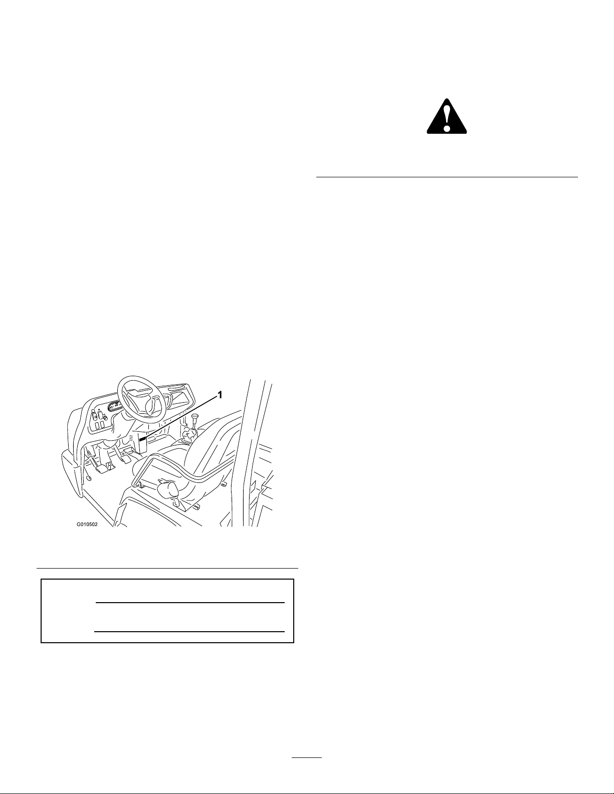
identiesthelocationofthemodelandserialnumbers
ontheproduct.Writethenumbersinthespace
provided.
Figure1
Figure2
1.Safetyalertsymbol
Thismanualuses2otherwordstohighlightinformation.
Importantcallsattentiontospecialmechanical
informationandNoteemphasizesgeneralinformation
worthyofspecialattention.
1.Modelandserialnumberlocation
ModelNo.
SerialNo.
©2011—TheToro®Company
8111LyndaleAvenueSouth
Bloomington,MN55420
Figure1
Contactusatwww.Toro.com.
2
PrintedintheUSA.
AllRightsReserved
Page 3

Contents
Introduction.................................................................2
Safety...........................................................................4
SafeOperatingPractices.......................................4
Supervisor’sResponsibilities.................................4
BeforeOperating.................................................4
Operation.............................................................5
Maintenance.........................................................6
SoundPressure.....................................................6
Vibration..............................................................6
SoundLevelCertication.....................................7
SafetyandInstructionalDecals.............................8
Setup..........................................................................13
1CheckingtheFluidLevels................................13
ProductOverview......................................................14
Controls.............................................................14
Specications.....................................................17
Attachments/Accessories...................................17
Operation...................................................................18
CheckingtheEngineOilLevel............................18
AddingFuel.......................................................19
CheckingtheCoolantLevel................................20
CheckingtheTransaxle/HydraulicFluid
Level..............................................................20
CheckingtheHighFlowHydraulicFluid(If
soequipped)...................................................21
CheckingtheFrontDifferentialOilLevel
(FourWheelDriveModelsOnly)....................21
CheckingtheTorqueoftheWheel
Nuts...............................................................22
CheckingtheTirePressure.................................22
CheckingtheBrakeFluid....................................22
Pre–startingChecks............................................23
StartingtheEngine.............................................23
DrivingtheV ehicle.............................................23
StoppingtheVehicle...........................................24
StoppingtheEngine...........................................24
NewVehicleBreak–in........................................24
CheckingtheInterlockSystem............................24
OperatingCharacteristics...................................25
Passengers..........................................................25
Speed.................................................................26
Turning..............................................................26
Braking..............................................................26
TipOvers...........................................................26
Hills...................................................................27
LoadingandDumping........................................27
FourWheelDrive(FourWheelDriveModels
Only)..............................................................28
TransportingtheVehicle.....................................28
TowingtheVehicle.............................................28
TowingaTrailerwiththeVehicle.........................29
Maintenance...............................................................30
RecommendedMaintenanceSchedule(s)................30
ServiceIntervalChart.........................................31
HeavyDutyOperation.......................................32
PremaintenanceProcedures....................................32
RemovingtheFullBed.......................................32
InstallingtheFullBed.........................................32
JackingtheVehicle..............................................33
RemovingtheHood...........................................33
Lubrication.............................................................34
GreasingBearingsandBushings.........................34
EngineMaintenance...............................................37
ServicingtheAirCleaner....................................37
ChangingtheEngineOilAndFilter....................37
FuelSystemMaintenance.......................................38
FuelLinesandConnections................................38
ServicingtheWaterSeparator/Fuel
Filter..............................................................38
ElectricalSystemMaintenance................................39
Fuses..................................................................39
JumpStartingtheVehicle....................................40
ServicingtheBattery...........................................40
DriveSystemMaintenance.....................................41
ChangingtheFrontDifferentialOil(Four
WheelDriveModelsOnly).............................41
InspectingtheConstantVelocityBoot(Four
WheelDriveModelsOnly).............................41
AdjustingtheShiftCables...................................42
AdjustingtheHigh–LowCable...........................42
InspectingtheTires............................................42
CheckingtheFrontWheelAlignment.................42
CoolingSystemMaintenance..................................43
RemovingDebrisfromtheCooling
System............................................................43
ChangingEngineCoolant...................................44
BrakeMaintenance.................................................45
AdjustingtheParkingBrake................................45
AdjustingtheBrakePedal...................................45
BeltMaintenance....................................................46
AdjustingBelts...................................................46
ControlsSystemMaintenance.................................46
AdjustingtheAcceleratorPedal..........................46
AdjustingtheClutchPedal..................................47
ConvertingtheSpeedometer..............................47
HydraulicSystemMaintenance...............................48
ChangingtheHydraulicFluidandCleaning
theStrainer.....................................................48
ReplacingtheHydraulicFilter.............................48
ChangingtheHighFlowHydraulicOiland
Filter(Ifsoequipped).....................................49
Storage.......................................................................50
Schematics.................................................................51
3
Page 4

Safety
ThemachinemeetstherequirementsofSAEJ2258.
Supervisors,operatorsandservicepersonsshouldbe
familiarwiththefollowingstandardsandpublications:
(Thematerialmaybeobtainedfromtheaddressshown).
•FlammableandCombustibleLiquidsCode:
ANSI/NFPA30
•NationalFireProtectionAssociation:
feelthanwhatdriversexperiencewithpassengercars
ortrucks.Sotaketimetobecomefamiliarwithyour
Workman.
NotalloftheattachmentsthatadapttotheW orkman
arecoveredinthismanual.SeethespecicOperator’s
Manualprovidedwitheachattachmentforadditional
safetyinstructions.Readthesemanuals.
Toreducethepotentialforinjuryordeath,comply
withthefollowingsafetyinstructions:
ANSI/NFPA#505;PoweredIndustrialTrucks
ADDRESS:
NationalFirePreventionAssociation
BarrymarchPark
Quincy,Massachusetts02269U.S.A
•ANSI/ASMEB56.8PersonalBurdenCarriers
ADDRESS:
AmericanNationalStandardsInstitute,Inc.
1430Broadway
NewYork,NewYork10018U.S.A.
•ANSI/UL558;InternalCombustionEngine
PoweredIndustrialTrucks
ADDRESS:
AmericanNationalStandardsInstitute,Inc.
1430Broadway
NewYork,NewYork10018U.S.A.
or
UnderwritersLaboratories333PngstenRoad
Northbrook,Illinois60062U.S.A.
SafeOperatingPractices
WARNING
TheWorkmanisanoff–highwayvehicleonly ,and
isnotdesigned,equipped,ormanufacturedforuse
onpublicstreets,roadsorhighways.
TheWorkmanwasdesignedandtestedtooffersafe
servicewhenoperatedandmaintainedproperly.
Althoughhazardcontrolandaccidentprevention
partiallyaredependentuponthedesignand
congurationofthemachine,thesefactorsarealso
dependentupontheawareness,concern,andproper
trainingofthepersonnelinvolvedintheoperation,
maintenanceandstorageofthemachine.Improperuse
ormaintenanceofthemachinecanresultininjuryor
death.
Thisisaspecializedutilityvehicledesignedforoff–road
useonly .Itsrideandhandlingwillhaveadifferent
Supervisor’sResponsibilities
•Makesureoperatorsarethoroughlytrainedand
familiarwiththeOperator’sManualandalllabelson
thevehicle.
•Besuretoestablishyourownspecialproceduresand
workrulesforunusualoperatingconditions(e.g.
slopestoosteepforvehicleoperation).Usethe3rd
HighLockoutswitchifhighspeedcouldresultina
safetyorvehicleabusesituation.
BeforeOperating
•Operatethemachineonlyafterreadingand
understandingthecontentsofthismanual.A
replacementmanualisavailablebysendingcomplete
modelandserialnumberto:TheToroCompany,
8111LyndaleAvenueSouth,Minneapolis,Minnesota
55420.
•Neverallowchildrentooperatethevehicle.Never
allowadultstooperateitwithoutproperinstructions.
Onlytrainedandauthorizedpersonsshouldoperate
thisvehicle.Makesurealloperatorsarephysically
andmentallycapableofoperatingthevehicle.
•Thisvehicleisdesignedtocarryonlyyou,the
operator,andonepassengerintheseatprovidedby
themanufacturer.Nevercarryanyotherpassengers
onthevehicle.
•Neveroperatethevehiclewhenundertheinuence
ofdrugsoralcohol.
•Becomefamiliarwiththecontrolsandknowhowto
stoptheenginequickly.
•Keepallshields,safetydevicesanddecalsinplace.
Ifashield,safetydeviceordecalismalfunctioning,
illegible,ordamaged,repairorreplaceitbefore
operatingthemachine.
•Alwayswearsubstantialshoes.Donotoperate
themachinewhilewearingsandals,tennisshoes,
orsneakers.Donotwearloosettingclothingor
jewelrywhichcouldgetcaughtinmovingpartsand
causepersonalinjury.
4
Page 5

•Wearingsafetyglasses,safetyshoes,longpants,anda
helmetisadvisableandrequiredbysomelocalsafety
andinsuranceregulations.
•Keepeveryone,especiallychildrenandpets,away
fromtheareasofoperation.
•Beforeoperatingthevehicle,alwayscheckallparts
ofthevehicleandanyattachments.Ifsomethingis
wrong,stopusingvehicle.Makesuretheproblem
iscorrectedbeforevehicleorattachmentisoperated
again.
•Sincedieselfuelishighlyammable,handleit
carefully.
–Useanapprovedfuelcontainer.
–Donotremovethecapfromthefueltankwhen
theengineishotorrunning.
–Donotsmokewhilehandlingfuel.
–Fillthefueltankoutdoorsandtoaboutoneinch
belowthetopoftank(bottomofllerneck).Do
notoverll.
–Wipeupanyspilledfuel.
•Operatethevehicleonlyoutdoorsorinawell
ventilatedarea.
•Useonlyanapprovednonmetal,portablefuel
container.Staticelectricdischargecanignitefuel
vaporsinaungroundedfuelcontainer.Removethe
fuelcontainerfromthebedofthevehicleandplace
itonthegroundawayfromthevehiclebeforelling.
Keepthenozzleincontactwiththecontainerwhile
lling.Removeequipmentfromvehiclebedbefore
lling.
•Checkthesafetyinterlocksystemdailyforproper
operation.Ifaswitchmalfunctions,replacethe
switchbeforeoperatingmachine.
Operation
•Theoperatorandpassengershoulduseseatbelts
andremainseatedwheneverthevehicleisinmotion.
Theoperatorshouldkeepbothhandsonthesteering
wheel,wheneverpossible,andthepassengershould
usethehandholdsprovided.Keeparmsandlegs
withinthevehiclebodyatalltimes.Nevercarry
passengersintheboxoronattachments.Remember
yourpassengermaynotbeexpectingyoutobrakeor
turnandmaynotbeready.
•Neveroverloadyourvehicle.Thenameplate
(locatedunderthemiddleofthedash)showsthe
loadlimitsforthevehicle.Neveroverllattachments
orexceedthevehiclemaximumgrossvehicleweight
(GVW).
•Whenstartingtheengine:
–Sitonoperator’sseatandensurethattheparking
brakeisengaged.
–DisengagePTO(ifsoequipped)andreturnthe
handthrottlelevertotheOffposition(ifso
equipped).
–MoveshiftlevertoNeutralandpresstheclutch
pedal.
–Keepyourfootoffoftheacceleratorpedal.
–TurnignitionswitchtotheOnposition.When
theglowplugindicatorgoesoff,theengineis
readytostart.
–TurntheignitionkeytotheStartposition.
Note:Theglowplugindicatorwillturnon,foran
additional15seconds,whentheswitchreturnsto
theOnposition.
•Usingthemachinedemandsattention.Failureto
operatevehiclesafelymayresultinanaccident,tip
overofthevehicle,andseriousinjuryordeath.
Drivecarefully.Topreventtippingorlossofcontrol,
takethefollowingprecautions:
–Useextremecaution,reducespeed,andmaintain
asafedistancearoundsandtraps,ditches,creeks,
ramps,anyunfamiliarareas,orotherhazards.
–Watchforholesorotherhiddenhazards.
–Usecautionwhenoperatingthevehicleona
steepslope.Normally,travelstraightupand
downslopes.Reducespeedwhenmakingsharp
turnsorwhenturningonhillsides.Avoidturning
onhillsideswheneverpossible.
–Useextracautionwhenoperatingthevehicleon
wetsurfaces,athigherspeeds,orwithafullload.
Stoppingtimewillincreasewithafullload.Shift
intoalowergearbeforestartingupordowna
hill.
–Whenloadingthebed,distributetheload
evenly.Useextracautioniftheloadexceeds
thedimensionsofthevehicle/bed.Operate
thevehiclewithextracautionwhenhandling
off-centerloadsthatcannotbecentered.Keep
loadsbalancedandsecuretopreventthemfrom
shifting.
–Avoidsuddenstopsandstarts.Donotgofrom
reversetoforwardorforwardtoreversewithout
rstcomingtoacompletestop.
–Donotattemptsharpturnsorabruptmaneuvers
orotherunsafedrivingactionsthatmaycausea
lossofvehiclecontrol.
–Donotpassanothervehicletravelinginthesame
directionatintersections,blindspots,oratother
dangerouslocations.
5
Page 6

–Keepallbystandersaway.Beforebackingup,
looktotherearandensurethatnooneisbehind
thevehicle.Backupslowly.
–Watchoutfortrafcwhennearorcrossingroads.
Alwaysyieldtherightofwaytopedestriansand
othervehicles.Thisvehicleisnotdesignedfor
useonstreetsorhighways.Alwayssignalyour
turnsorstopearlyenoughsootherpersons
knowwhatyouplantodo.Obeyalltrafcrules
andregulations.
–Neveroperatethevehicleinornearanarea
wherethereisdustorfumesintheairwhichare
explosive.Theelectricalandexhaustsystems
ofthevehiclecanproducesparkscapableof
ignitingexplosivematerials.
–Alwayswatchoutforandavoidlowoverhangs
suchastreelimbs,doorjambs,overhead
walkways,etc.Makesurethereisenoughroom
overheadtoeasilyclearthevehicleandyour
head.
–Ifeverunsureaboutsafeoperation,stopwork
andaskyoursupervisor.
•Donottouchengine,transaxle,radiator,muferor
mufermanifoldwhileengineisrunningorsoon
afterithasstoppedbecausetheseareasmaybehot
enoughtocauseburns.
•Ifthemachineevervibratesabnormally,stop
immediately,turnengineoff,waitforallmotion
tostopandinspectfordamage.Repairalldamage
beforeresumingoperation.
•Beforegettingofftheseat:
–Stopmovementofthemachine.
–Shutengineoffandwaitforallmovementto
stop.
–Setparkingbrake.
–Removekeyfromignition.
•Lightningcancausesevereinjuryordeath.If
lightningisseenorthunderisheardinthearea,do
notoperatethemachine;seekshelter.
highpressure.Usepaperorcardboard,nothands,
tosearchforleaks.Hydraulicuidescapingunder
pressurecanhavesufcientforcetopenetrateskin
anddoseriousdamage.Ifuidisinjectedintothe
skinitmustbesurgicallyremovedwithinafew
hoursbyadoctorfamiliarwiththisformofinjury
organgrenemayresult.
•Tomakesuretheentiremachineisingoodcondition,
keepallnuts,bolts,andscrewsproperlytightened.
•Toreducethepotentialrehazard,keeptheengine
areafreeofexcessivegrease,grass,leaves,and
accumulationofdirt.
•Iftheenginemustberunningtoperforma
maintenanceadjustment,keephands,feet,clothing,
andanypartsofthebodyawayfromtheengineand
anymovingparts.Keepeveryoneaway.
•Donotoverspeedtheenginebychangingthe
governorsettings.Themaximumenginespeedis
3650RPM.Toensuresafetyandaccuracy,havean
AuthorizedToroDistributorcheckthemaximum
enginespeedwithatachometer.
•Ifmajorrepairsareeverneededorassistanceis
required,contactanAuthorizedToroDistributor.
•Tobesureofoptimumperformanceandsafety,
alwayspurchasegenuineTororeplacementpartsand
accessories.Replacementpartsandaccessoriesmade
byothermanufacturerscouldbedangerous.Altering
thisvehicleinanymannermayaffectthevehicle’s
operation,performance,durabilityoritsusemay
resultininjuryordeath.Suchusecouldvoidthe
productwarrantyofTheToro®Company.
•Thisvehicleshouldnotbemodiedwithout
TheToro®Company’sauthorization.Directany
inquiriestoTheToro®Company ,Commercial
Division,VehicleEngineeringDept.,8111Lyndale
Ave.So.,Bloomington,Minnesota55420–1196.
USA
SoundPressure
Maintenance
•Beforeservicingormakingadjustmentstothe
machine,stoptheengine,settheparkingbrake,and
removethekeyfromignitiontopreventaccidental
startingoftheengine.
•Makesureallhydrauliclineconnectorsaretight,and
allhydraulichosesandlinesareingoodcondition
beforeapplyingpressuretothesystem.
•Keepyourbodyandhandsawayfrompinhole
leaksornozzlesthatejecthydraulicuidunder
Thisunithasasoundpressurelevelattheoperator’ s
earof82dBA,whichincludesanUncertaintyValue(K)
of1dBA.
Thesoundpressurelevelwasdeterminedaccordingto
theproceduresoutlinedinENISO11201.
Vibration
Hand-Arm
•Measuredvibrationlevelforrighthand=0.41m/s
6
2
Page 7

•Measuredvibrationlevelforlefthand=0.2m/s
•UncertaintyValue(K)=0.5m/s
2
Measuredvaluesweredeterminedaccordingtothe
proceduresoutlinedinEN1032.
WholeBody
•Measuredvibrationlevel=0.3m/s
•UncertaintyValue(K)=0.5m/s
Measuredvaluesweredeterminedaccordingtothe
proceduresoutlinedinEN1032.
2
2
SoundLevelCertication
WhentestedperITSDFB56-11-5-2005thevehicle
meetsAlcoa30.3.2Section4.1.2aforenginespeedsup
to:
•3650withoutcab@80dBA
•2850withcab@80dBA
2
7
Page 8

SafetyandInstructionalDecals
Safetydecalsandinstructionsareeasilyvisibletotheoperatorandarelocatednearanyareaof
potentialdanger.Replaceanydecalthatisdamagedorlost.
93-9852
1.Warning—readtheOperator’sManual.2.Crushinghazard—installthecylinderlock.
115-7739
1.Falling,crushinghazard,bystanders—noriderson
machine.
1.Warning—donottouchthehotsurface.
1.Liftpoint
115-2047
93-9084
115-7723
1.Warning—thehydraulicoilpressureis124bar(1800PSI).
2.CouplerA
3.CouplerB
2.Tie-downpoint
115-7740
1.Warning—maximumtrailerweightis1500lb(680kg),
maximumtongueweightis200lb(90kg).
2.Warning—trailerbrakesarerequiredwhentowinggreater
than1500lb(680kg),maximumtrailerweightwithtrailer
brakesis3500lb(1591kg),maximumtongueweightwith
trailerbrakesis600lb(273kg).
8
Page 9
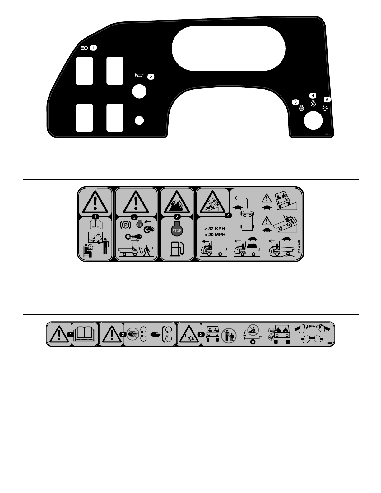
1.Headlights4.Engine—run
2.Horn5.Engine—start
3.Engine—stop
1.Warning—donotoperatethismachineunlessyouaretrained.
2.Warning—locktheparkingbrake,stoptheengine,and
removetheignitionkeybeforeleavingthemachine.
115-2281
115-7746
3.Firehazard—stoptheenginebeforefueling.
4.Tippinghazard—slowdownandturngradually ,usecaution
anddriveslowlywhendrivingonslopes,donotexceed20
mph(32kph),anddriveslowlyoverroughterrainorwhen
carryingafullorheavyload.
115-2282
1.Warning—readtheOperator’sManual.
2.Warning—stayawayfrommovingparts,keepallguardsandshieldsinplace.
3.Crushing/dismembermenthazardofbystanders—keepbystandersasafedistancefromthevehicle,donotcarrypassengersin
thecargobed,keeparmsandlegsinsideofthevehicleatalltimes,anduseseatbeltsandhandholds.
9
Page 10
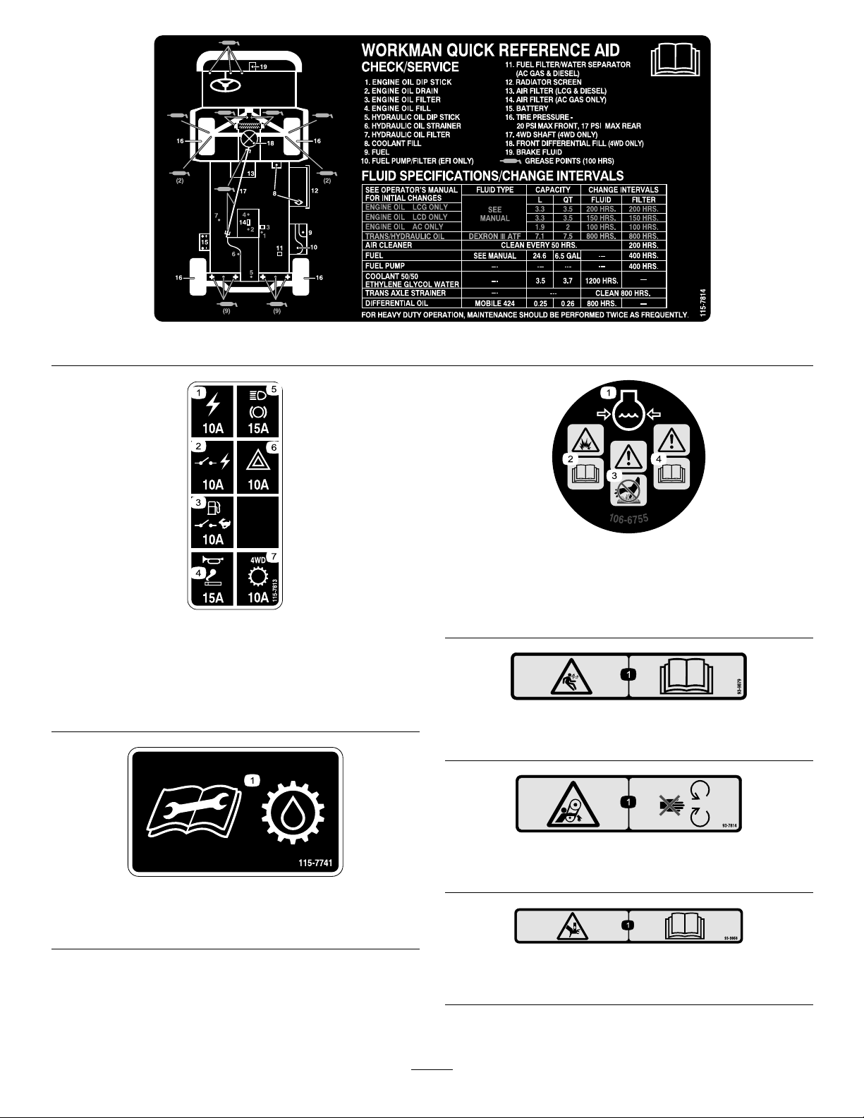
115-7813
1.Poweroutlet10A5.Lights,brake15A
2.Switchedpower10A
3.Fuelpump,supervisor
switch10A
4.Horn,powerpoint15A
6.Hazard10A
7.4WD,Transmission10A
115-7814
106-6755
1.Enginecoolantunder
pressure.
2.Explosionhazard—read
theOperator’sManual.
3.Warning—donottouch
thehotsurface.
4.Warning—readthe
Operator’sManual.
93-9879
1.Storedenergyhazard—readtheOperator’sManual.
115-7741
1.ReadtheOperator’sManualbeforeservicingtransmission
uid.
93-7814
1.Entanglementhazard,belt—stayawayfrommovingparts.
93–9868
1.Crushinghazardofhand—readtheOperator’sManual.
10
Page 11
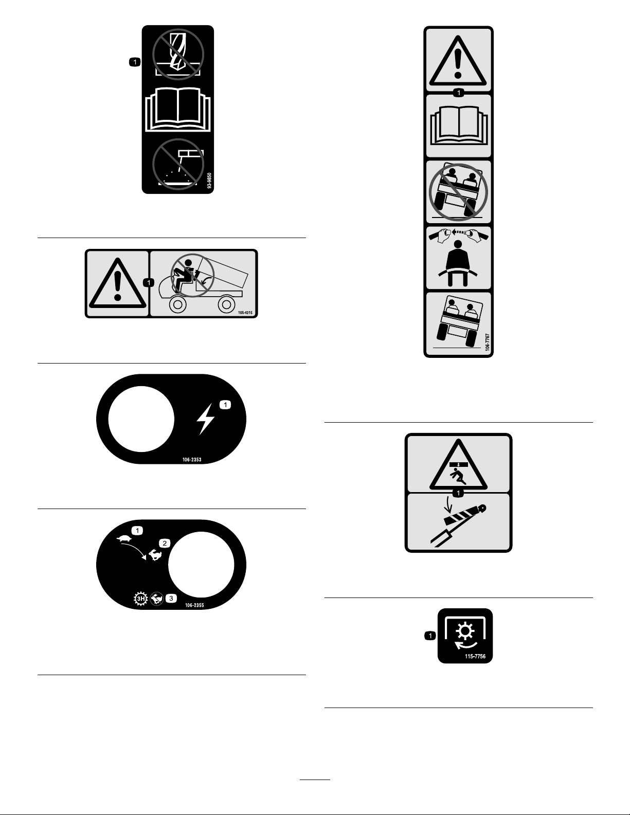
93-9850
93-9899
1.Donotrepairorrevise—readtheOperator’sManual.
105-4215
1.Warning—avoidpinchpoints.
106-2353
1.Electricalpowerpoint
106-7767
1.Warning—readtheOperator’sManual;avoidtippingthe
machine;weartheseatbelt;leanawayfromthedirection
themachineistipping.
93-9899
1.Crushinghazard—installthecylinderlock.
106-2355
1.Slow
2.Fast
3.Transmission—thirdhigh;
nofastspeed
115-7756
1.Highowhydraulics—engaged
11
Page 12
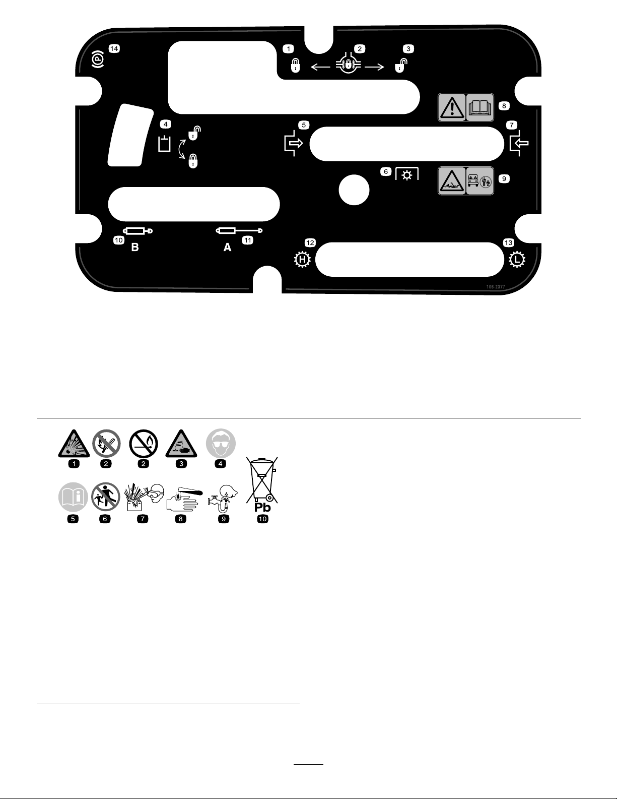
106-2377
1.Locked
2.Differentiallock9.Entanglementhazard,shaft—keepbystander’sasafe
3.Unlocked10.Retracthydraulics
4.Hydrauliclock11.Extendhydraulics
5.Engage12.Transmission—highspeed
6.Powertake-off(PTO)
7.Disengage14.Parkingbrake
8.Warning—readtheOperator’sManual.
distancefromthevehicle.
13.Transmission—lowspeed
BatterySymbols
Someorallofthesesymbolsareonyourbattery
1.Explosionhazard
2.Nore,opename,or
smoking.
3.Causticliquid/chemical
burnhazard
4.Weareyeprotection9.Flusheyesimmediately
5.ReadtheOperator’s
Manual.
6.Keepbystandersasafe
distancefromthebattery .
7.Weareyeprotection;
explosivegasescan
causeblindnessandother
injuries
8.Batteryacidcancause
blindnessorsevereburns.
withwaterandgetmedical
helpfast.
10.Containslead;donot
discard.
12
Page 13

Setup
LooseParts
Usethechartbelowtoverifythatallpartshavebeenshipped.
ProcedureDescription
1
Nopartsrequired
MediaandAdditionalParts
Description
Operator’sManual
PartsManual1
OperatorTrainingMaterial
Note:Determinetheleftandrightsideofthemachine
fromthenormaloperatingposition.
1
CheckingtheFluidLevels
Qty.
Qty.
–
1
1
Readbeforeoperatingthevehicle
Usetoreferencepartnumbers
Viewbeforeoperatingmachine
Checktheengineoil,transaxle/hydraulic
uid,andbrakeuidlevels
Use
Use
NoPartsRequired
Procedure
1.Checktheengineoillevelbeforeandaftertheengine
isrststarted,refertoCheckingtheEngineOil
LevelinOperation.
2.Checkthetransaxle/hydraulicuidlevelbefore
theengineisrststarted,refertoCheckingthe
Transaxle/HydraulicFluidLevelinOperation.
3.Checkthebrakeuidlevelbeforetheengineisrst
started,refertoCheckingtheBrakeFluidLevelin
Operation.
13
Page 14
ProductOverview
Controls
Note:Determinetheleftandrightsidesofthemachine
fromthenormaloperatingposition.
AcceleratorPedal
Theacceleratorpedal(Figure3)givestheoperator
theabilitytovarytheengineandgroundspeedofthe
vehicle,whenthetransmissionisingear.Pressing
thepedalincreasesengineRPMandgroundspeed.
ReleasingthepedalwilldecreaseengineRPMand
groundspeedofthemachine.
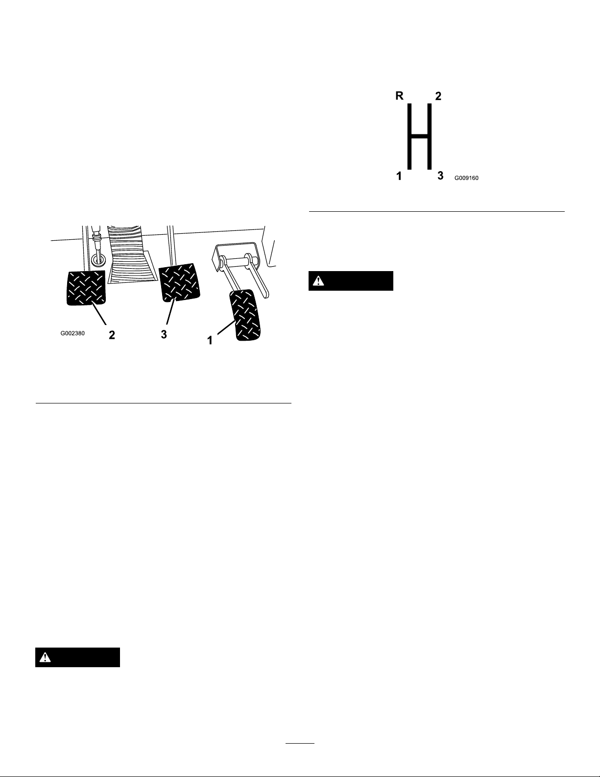
GearShiftLever
Fullypresstheclutchpedalandmovetheshiftlever
Figure4)intothedesiredgearselection.Adiagramof
(
theshiftpatternisindicatedbelow .
Figure4
Important:Donotshiftthetransaxletothereverse
orforwardgearunlessthevehicleisstandingstill.
Damagetothetransaxlemayoccur.
CAUTION
Downshiftingfromtoohighaspeedcancause
therearwheelstoskidresultinginlossofvehicle
controlaswellasclutchand/ortransmission
damage.Shiftsmoothlytoavoidgrindinggears.
Figure3
1.Acceleratorpedal3.Brakepedal
2.Clutchpedal
ClutchPedal
Theclutchpedal(Figure3)mustbefullypressedto
disengageclutchwhenstartingtheengineorshifting
transmissiongears.Releasethepedalsmoothlywhenthe
transmissionisingeartopreventunnecessarywearon
thetransmissionandotherrelatedparts.
Important:Donotridetheclutchpedalduring
operation.Theclutchpedalmustbefullyoutorthe
clutchwillslipcausingheatandwear.Neverhold
thevehiclestoppedonahillusingtheclutchpedal.
Damagetotheclutchmayoccur.
BrakePedal
Thebrakepedal(Figure3)isusedtoapplyservice
brakestostoporslowvehicle.
ParkingBrake
Whenevertheengineisshutoff,theparkingbrake
(Figure5)mustbeengagedtopreventaccidental
movementofthevehicle.Toengagetheparkingbrake,
pullbackonthelever.Todisengage,pushthelever
forward.Releasetheparkingbrakebeforemovingthe
vehicle.Ifyouparkthevehicleonasteepgrade,apply
theparkingbrake.Also,shiftthetransmissioninto1st
gearonauphillgradeorreverseonadownhillgrade.
Placechocksatthedownhillsideofthewheels.
CAUTION
Wornormaladjustedbrakesmayresultinpersonal
injury.Ifthebrakepedaltravelstowithin1-1/2
inches(3.8cm)ofthevehicleoorboard,thebrakes
mustbeadjustedorrepaired.
14
Page 15
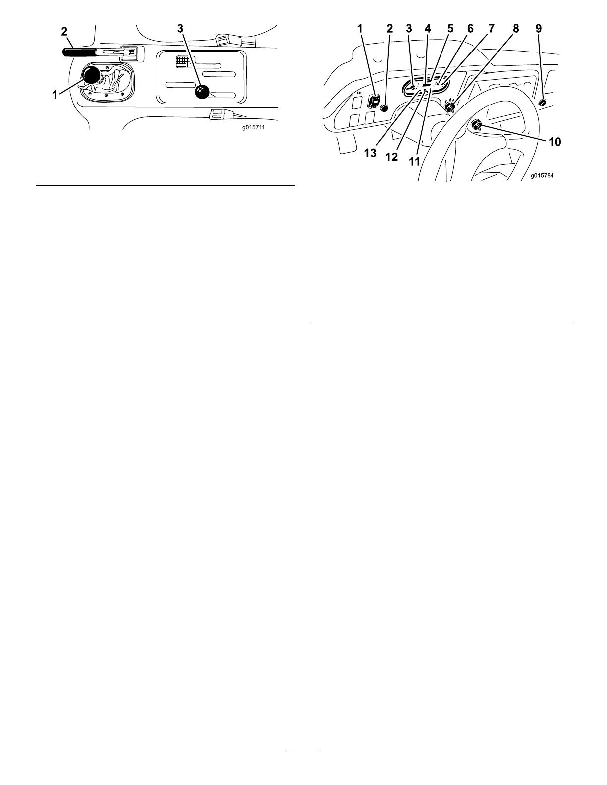
Figure5
1.Gearshiftlever3.High–lowrangeshifter
2.Parkingbrake
High–LowRangeShifter
Thehigh–lowrangeshifteraddsthreeadditionalspeeds
forprecisespeedcontrol(Figure5).
•Thevehiclemustbecompletelystoppedbefore
shiftingbetweenHighandLowrange.
•Shiftonlyonlevelground.
•Pressclutchpedalfully.
•MovetheleverfullyforwardforHighandfully
rearwardforLow.
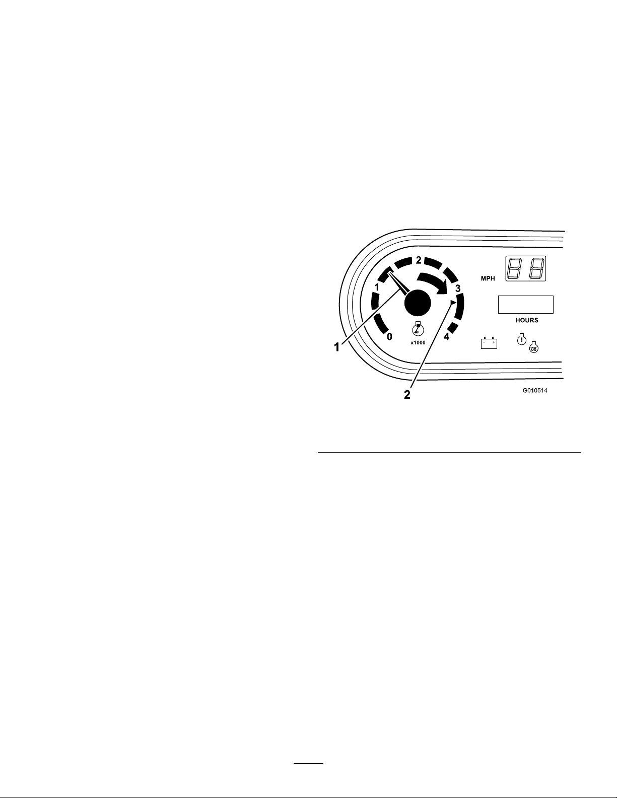
Figure6
1.Highow
hydraulicsswitch
(Optional)
2.Horn9.Powerpoint
3.Tachometer10.3rdhighlockoutswitch
4.Hourmeter
5.Speedometer12.Glowplugindicator
6.Coolanttemperature
gaugeandlight
7.Fuelgauge
8.Ignitionswitch
11.Oilpressurewarninglight
13.Chargeindicator
HourMeter
Highisforhigherspeeddrivingonlevel,drysurfaces
withlightloads.
Lowisforlowspeeddriving.Usethisrangewhen
greaterthannormalpowerorcontrolisrequired.For
example,steepgrades,difcultterrain,heavyloads,slow
speedbuthighenginespeed(spraying).
Important:ThereisalocationbetweenHighand
Lowinwhichthetransaxleisinneitherrange.
Donotusethispositionasaneutralposition
becausethevehiclecouldmoveunexpectedlyif
theHigh–Lowshifterisbumpedandthegearshift
leverisingear.
IgnitionSwitch
Usetheignitionswitch(Figure6)tostartandstopthe
engine.Ithasthreepositions:Off,On/Preheat,and
Start.RotatethekeyclockwisetotheStartpositionto
engagethestartermotor.Releasethekeywhenthe
enginestarts.Thekeywillmoveautomaticallytothe
Onposition.Toshuttheengineoff,rotatethekey
counterclockwisetotheOffposition.
Indicatesthetotalhoursofmachineoperation.The
hourmeter(Figure6)startstofunctionwheneverthe
keyswitchisrotatedtotheOnpositionoriftheengine
isrunning.
3rdHighLockoutSwitch
Movethe3rdhighlockoutswitch(Figure6)totheslow
positionandremovethekeytopreventtheuseofthird
gearwhenintheHighrange.Theenginewillshutoff
iftheshiftleverismovedtothirdgearwheninHigh
range.Thekeyisremovableineitherposition.
OilPressureWarningLight
Theoilpressurewarninglightglows(Figure6)ifthe
engineoilpressuredropsbelowasafelevelwhilethe
engineisrunning.Ifthelightickersorremainson,
stopthevehicle,turnofftheengine,andchecktheoil
level.Iftheoillevelwaslow ,butaddingoildoesnot
causethelighttogooutwhentheengineisrestarted,
turntheengineoffimmediatelyandcontactyourlocal
Torodistributorforassistance.
Checktheoperationofwarninglightsasfollows:
1.Applytheparkingbrake.
2.TurntheignitionkeytotheOn/Preheatposition,
butdonotstarttheengine.Theoilpressurelight
shouldglowred.Ifthelightdoesnotfunction,
15
Page 16
eitherabulbisburnedoutorthereisamalfunction
inthesystemwhichmustberepaired.
HighFlowHydraulicsSwitch(Ifso
equipped)
Note:Ifenginewasjustturnedoff,itmaytake1to2
minutesforthelighttocomeon.
LowOilPressureShutDown
Iftheengineoilpressuredropsbelowasafelevel,
formorethan10seconds,theenginewillshutdown.
ContactyourlocalTorodistributorforassistance.
GlowPlugIndicator
Glowplugindicator(Figure6)willglowredwhenthe
glowplugsareactivated.
Important:Theglowplugindicatorwillturn
on,foranadditional15seconds,whentheswitch
returnstotheOnposition.
CoolantTemperatureGaugeandLight
Registersthecoolanttemperatureintheengine.
OperatesonlywhentheignitionswitchisinOnposition
(Figure6).Theindicatorlightwillilluminateblinking
rediftheengineoverheats.
Turnontheswitchtoactivatethehighowhydraulics
(Figure6).
HornButton
Pressingthehornbuttonactivatesthehorn(Figure6).
Tachometer
RegisterstheRPMoftheengine(Figure6&Figure7).
WhitetriangleindicatesdesiredRPMforPTOoperation
(Figure7).
ChargeIndicator
Illuminateswhenbatteryisbeingdischarged.Iflight
illuminatesduringoperation,stopvehicle,turnoff
engineandcheckforpossiblecauses,suchasalternator
Figure6).
belt(
Important:Ifalternatorbeltislooseorbroken,do
notoperatethevehicleuntiladjustmentorrepairis
complete.Failuretoobservethisprecautionmay
resultindamagetotheengine.
Checktheoperationofwarninglightsasfollows:
•Applyparkingbrake.
•TurntheignitionkeytotheOn/Preheatposition,
butdonotstarttheengine.Thecoolanttemperature,
chargeindicator,andoilpressurelightsshouldglow .
Ifanylightdoesnotfunction,eitherabulbisburned
outorthereisamalfunctioninthesystemwhich
mustberepaired.
FuelGauge
Figure7
1.RPMoftheengine2.3300RPMfor540RPM
PTOoperation
Speedometer
Registersthegroundspeedofthevehicle(Figure6).
ThespeedometerisinMPHbutcaneasilyconvertedto
KPH.RefertoConvertingtheSpeedometerinControls
Maintenance.
PowerPoint
Usethepowerpoint(Figure6)topoweroptional12
voltelectricalaccessories.
PassengerHandHold
Thepassengerhandholdislocatedonthedashboard
(Figure8).
Thefuelgaugeshowstheamountoffuelinthetank.It
operatesonlywhenignitionswitchisintheOn/Preheat
position(
blinkingredindicatesnearempty.
Figure6).Redindicateslowfuelleveland
16
Page 17
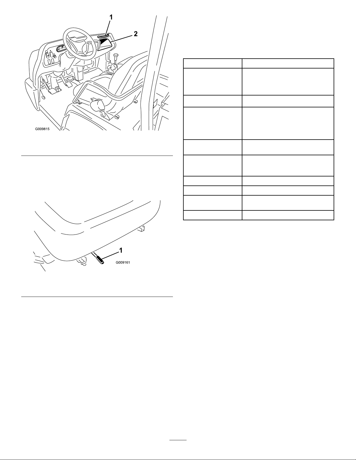
Figure8
1.Passengerhandhold
2.Storagecompartment
SeatAdjustingLever
Theseatscanbeadjustedforeandaftforoperator
comfort(
Figure9).
Specications
Note:Specicationsanddesignaresubjecttochange
withoutnotice.
Dimensions
OverallWidth63inches(160cm)
w/obed:128.25inches(326cm)
OverallLength
BaseWeight(Dry)1806lb(819kg)
RatedCapacity
(includes200lb.
operator,200lb.
passengerandloaded
attachment).
Maximum.Gross
VehicleWeight
TowCapacityT ongueweight600lb(272kg)
GroundClearance7inches(18cm)w/noload
WheelBase
WheelTread(center
linetocenterline)
Height
w/fullbed:130.38inches(331cm)
w/2/3bedinrearmountinglocation:
136.38inches(346cm)
3044lb(1381kg)
4,850lb(2200kg)
Maximumtrailerweight3,500lb(1587
kg)
70inches(1 18cm)
Front:46inches(117cm)
Rear:47.7inches(121cm)
75inches(190.5cm)totopofROPS
1.Seatadjustinglever
Figure9
Attachments/Accessories
AselectionofToroapprovedattachmentsand
accessoriesareavailableforusewiththemachineto
enhanceandexpanditscapabilities.Contactyour
AuthorizedServiceDealerorDistributororgoto
www.Toro.comforalistofallapprovedattachments
andaccessories.
17
Page 18

Operation
Note:Determinetheleftandrightsidesofthe
machinefromthenormaloperatingposition.
CAUTION
Beforeservicingormakingadjustmentstothe
machine,stoptheengine,settheparkingbrake,
andremovethekeyfromtheswitch.
CheckingtheEngineOilLevel
ServiceInterval:Beforeeachuseordaily
Theengineisshippedwithapproximately3.5quarts
(3.3l)(w/lter)ofoilinthecrankcase;however,you
shouldchecktheoillevelbeforeandaftertheengine
isrststarted.
Note:Thebesttimetochecktheengineoiliswhen
theengineiscoolbeforeithasbeenstartedforthe
day.Ifithasalreadybeenrun,allowtheoiltodrain
backdowntothesumpforatleast10minutesbefore
checking.IftheoillevelisatorbelowtheAddmark
onthedipstick,addoiltobringtheoilleveltotheFull
mark.Donotoverll.Iftheoillevelisbetweenthe
FullandAddmarks,noadditionaloilisrequired.
Theengineusesanyhigh-quality10W-30detergent
oilhavingtheAmericanPetroleumInstitute(API)
serviceclassicationCForhigher.Chooseaviscosity
accordingtothetablein
Figure10.
Figure11
1.Dipstick
3.Iftheoillevelislow,removethellercap
Figure12)andaddenoughoiltoraisethelevelto
(
theFullmarkonthedipstick.
Figure12
1.Fillercap
Figure10
1.Positionthemachineonalevelsurface.
2.Removethedipstickandwipeitwithacleanrag.
Insertthedipstickintothetubeandmakesureitis
seatedfully.Removedipstickandcheckthelevel
oftheoil.
Note:Whenaddingoil,removedipsticktoallow
properventing.Pouroilslowlyandcheckthelevel
oftenduringthisprocess.Donotoverll.
Important:Whenaddingengineoilorlling
oil,theremustbeclearancebetweentheoilll
deviceandtheoilllholeinthevalvecoveras
showninFigure13.Thisclearanceisnecessary
topermitventingwhenlling,whichprevents
oilfromoverrunningintothebreather.
18
Page 19

Figure13
1.Noteclearance
4.Installthedipstickrmlyinplace.
DANGER
Undercertainconditions,dieselfuelandfuel
vaporsarehighlyammableandexplosive.Are
orexplosionfromfuelcanburnyouandothersand
cancausepropertydamage.
•Beforeremovingthefueltankcap,makesure
thevehicleispositionedonalevelsurface.
Openfueltankcapslowly.
•Useafunnelandllthefueltankoutdoors,
inanopenarea,whentheengineisoffandis
cold.Wipeupanyfuelthatspills.
•Donotllthefueltankcompletelyfull.Add
fueltothefueltankuntilthelevelis1in.(25
mm)belowthebottomofthellerneck.This
emptyspaceinthetankallowsthefuelto
expand.
•Neversmokewhenhandlingfuel,andstay
awayfromanopenameorwherefuelfumes
maybeignitedbyaspark.
AddingFuel
Useonlyclean,freshdieselfuelorbiodieselfuelswith
low(<500ppm)orultralow(<15ppm)sulfurcontent.
Theminimumcetaneratingshouldbe40.Purchase
fuelinquantitiesthatcanbeusedwithin180daysto
ensurefuelfreshness.
Fueltankcapacity:6.5USgallons(25l).
Usesummergradedieselfuel(No.2-D)attemperatures
above20°F(-7°C)andwintergrade(No.1-Dor
No.1-D/2-Dblend)belowthattemperature.Useof
wintergradefuelatlowertemperaturesprovideslower
ashpointandcoldowcharacteristicswhichwillease
startingandreducefuellterplugging.
Useofsummergradefuelabove20°F(-7°C)will
contributetowardlongerfuelpumplifeandincreased
powercomparedtowintergradefuel.
Important:Donotusekeroseneorgasoline
insteadofdieselfuel.Failuretoobservethis
cautionwilldamagetheengine.
WARNING
Fuelisharmfulorfatalifswallowed.Long-term
exposuretovaporscancauseseriousinjuryand
illness.
•Avoidprolongedbreathingofvapors.
•Keepyourfaceawayfromthenozzleandgas
tankorconditioneropening.
•Keepfuelawayfromyoureyesandskin.
•Storefuelinaclean,safety-approvedcontainer
andkeepthecapinplace.
BiodieselReady
Thismachinecanalsouseabiodieselblendedfuel
ofuptoB20(20%biodiesel,80%petrodiesel).The
petrodieselportionshouldbeloworultralowsulfur.
Observethefollowingprecautions:
•Thebiodieselportionofthefuelmustmeet
specicationASTMD6751orEN14214.
•TheblendedfuelcompositionshouldmeetASTM
D975orEN590.
•Paintedsurfacesmaybedamagedbybiodiesel
blends.
•UseB5(biodieselcontentof5%)orlesserblends
incoldweather.
•Monitorseals,hoses,gasketsincontactwithfuelas
theymaybedegradedovertime.
•Fuellterpluggingmaybeexpectedforatimeafter
convertingtobiodieselblends.
•Contactyourdistributorifyouwishformore
informationonbiodiesel.
1.Cleantheareaaroundthefueltankcap.
2.Removethefueltankcap(
shieldremoved).
Figure14,shownwith
19
Page 20

Figure14
1.Fueltankcap
3.Fillthetanktoaboutoneinchbelowthetopofthe
tank,(bottomofthellerneck),theninstallthecap.
Donotoverll.
Figure15
1.Reservetank
2.Hotline
3.Ifcoolantislow ,removethereservetankcap
andadda50/50mixtureofwaterandpermanent
ethyleneglycolantifreeze.Donotoverll.
4.Installthereservetankcap.
3.Coldline
4.Wipeupanyfuelthatmayhavespilledtopreventa
rehazard.
CheckingtheCoolantLevel
ServiceInterval:Beforeeachuseordaily
Coolingsystemcapacity:4qt(3.7l)
Thecoolingsystemislledwitha50/50solutionof
waterandpermanentethyleneglycolantifreeze.
1.Parkthemachineonalevelsurface.
CAUTION
Iftheenginehasbeenrunning,thepressurized,
hotcoolantcanescapeandcauseburns.
•Donotopentheradiatorcapwhenthe
engineisrunning.
•Allowtheenginetocoolatleast15minutes
oruntiltheradiatorcapiscoolenoughto
touchwithoutburningyourhand.
Checkingthe
Transaxle/HydraulicFluid
Level
ServiceInterval:Beforeeachuseordaily
ThetransaxlereservoirislledwithDexronIIIATF.
Checkthelevelbeforetheengineisrststartedand
every8hoursordaily,thereafter.Capacityofsystemis.
Transaxlereservoircapacity:7.5qt(7l).
1.Positionthevehicleonalevelsurface.
2.Cleantheareaaroundthedipstick(
Figure16).
•Usearagwhenopeningtheradiatorcap,
andopenthecapslowlytoallowsteamto
escape.
2.Checkthecoolantlevelonthesideofthereserve
tank(Figure15).Thecoolantshouldbeuptothe
Coldline,whenengineiscold.
Figure16
1.Dipstick
20
Page 21

3.Unscrewthedipstickfromthetopofthetransaxle
andwipeitwithacleanrag.
4.Screwthedipstickintothetransaxleandensurethat
itisfullyseated.
5.Unscrewthedipstickandchecktheuidlevel.
Theuidshouldbeuptotopoftheatportion
ofthedipstick.
6.Ifthelevelislow,addenoughuidtoachievethe
properlevel.
CheckingtheHighFlow
HydraulicFluid(Ifso
equipped)
ServiceInterval:Beforeeachuseordaily
Thehighowhydraulicsreservoirislledwith
approximately4USgallons(15l)ofhighquality
hydraulicuid.Checkthelevelofhydraulic
uidbeforetheengineisrststartedanddaily
thereafter.
1.Cleantheareaaroundthellerneckandthecap
ofthehydraulictank(Figure17).Removethecap
fromthellerneck.
WARNING
Hydraulicuidescapingunderpressurecan
penetrateskinandcauseinjury.
•Makesureallhydraulicuidhosesand
linesareingoodconditionandallhydraulic
connectionsandttingsaretightbefore
applyingpressuretothehydraulicsystem.
•Keepyourbodyandhandsawayfrompin
holeleaksornozzlesthatejecthighpressure
hydraulicuid.
•Usecardboardorpapertondhydraulic
leaks.
•Safelyrelieveallpressureinthehydraulic
systembeforeperforminganyworkonthe
hydraulicsystem.
•Seekimmediatemedicalattentionifuidis
injectedintoyourskin.
CheckingtheFront
DifferentialOilLevel(Four
WheelDriveModelsOnly)
ServiceInterval:Every100hours/Monthly
(whichevercomesrst)
Figure17
1.Cap
2.Removethedipstick(Figure17)fromthellerneck
andwipeitwithacleanrag.Insertthedipstickinto
thellerneck;thenremoveitandchecktheuid
level.Theuidlevelshouldbebetweenthetwo
marksonthedipstick.
3.Ifthelevelislow ,addtheappropriateuidtoraise
theleveltotheuppermark.RefertoChangingthe
HighFlowHydraulicFluid
4.Installthedipstickandcapontothellerneck.
5.Starttheengineandturnontheattachment.Let
themrunforabouttwominutestopurgeairfrom
thesystem.Stoptheengineandattachmentand
checkforleaks.
Important:Thevehiclemustberunning
beforestartingthehighowhydraulics.
ThedifferentialislledwithMobil424hydraulicoil.
1.Positionthevehicleonalevelsurface.
2.Cleantheareaaroundthell/checkplugonsideof
thedifferential(Figure18).
Figure18
1.Fill/checkplug
3.Removethell/checkplugandcheckthelevelof
theoil.Theoilshouldbeuptohole.Iftheoilis
low,addMobil424hydraulicoil.
4.Installthell/checkplug.
2.Drainplug
21
Page 22

CheckingtheTorqueofthe
WheelNuts
ServiceInterval:Aftertherst2hours
Aftertherst10hours
Every200hours
WARNING
Failuretomaintainpropertorqueofthewheelnuts
couldresultinfailureorlossofawheelandmay
resultinpersonalinjury.
Torquethefrontandrearwheelnutsto80to90
ft-lb(109to122N-m)after1to4hoursofoperation
andagainafter10hoursofoperation.T orqueevery
200hoursthereafter.
CheckingtheTirePressure
ServiceInterval:Beforeeachuseordaily
Themaximumairpressureinthefronttiresis32psi
(220kPa)andthereartiresis20psi(138kPa).
Checkthetirepressurefrequentlytoensureproper
ination.Ifthetiresarenotinatedtothecorrect
pressure,thetireswillwearprematurely.
Figure19isanexampleoftirewearcausedbyunder
ination.
Figure20
1.Overinatedtire
CheckingtheBrakeFluid
ServiceInterval:Beforeeachuseordaily—Checkthe
brakeuidlevel.
Every1,000hours/Every2years
(whichevercomesrst)—Change
thebrakeuid.
Thebrakeuidreservoirisshippedfromthefactory
lledwithDOT3brakeuid.Checkthelevelbefore
theengineisrststartedandevery8hoursordaily,
thereafter.
Thebrakeuidreservoirislocatedunderthedash.
1.Parkthemachineonalevelsurface.
2.TheuidlevelshouldbeuptotheFulllineonthe
reservoir(
Figure21).
Figure19
1.Underinatedtire
Figure20isanexampleoftirewearcausedbyover
ination.
Figure21
1.Brakeuidreservoir
3.Iftheuidlevelislow ,cleantheareaaroundthe
cap,removethereservoircap,andllthereservoir
totheproperlevel.Donotoverll.
Note:Youcanremovethehoodaccesstothereservoir
fromthefrontofthemachine(
22
Figure22).
Page 23

Figure22
1.Brakeuidreservoir
Pre–startingChecks
Safeoperationbeginsbeforetakingthevehicleoutfor
aday’swork.Y oushouldchecktheseitemseachtime:
•Checkthetirepressure.
•Checkalluidlevelsandaddtheappropriate
amountofTorospecieduids,ifanyarefound
tobelow .
•Initialstartupofanewmachine.
•Theenginehasceasedrunningduetolackoffuel.
•Youhaveperformedmaintenanceuponthefuel
systemcomponents;i.e.,lterreplaced,separator
serviced,etc.
1.Sitontheoperator’sseatandengagetheparking
brake.
2.DisengagethePTOandhighowhydraulics(ifso
equipped)andmovethehandthrottlelevertothe
Offposition(ifsoequipped).
3.MovetheshiftlevertotheNeutralpositionand
presstheclutchpedal.
4.Keepyourfootoffoftheacceleratorpedal.
5.TurntheignitionswitchtotheOnposition.When
theglowplugindicatorlightgoesoff,theengineis
readytostart.
6.RotatetheignitionkeyswitchtotheStartposition.
Releasethekeyimmediatelywhentheenginestarts
andallowittoreturntotheOnposition.
Note:Theglowplugindicatorwillturnonforan
additional15seconds,whentheswitchreturnstothe
Onposition.
Note:Donotrunthestartermotormorethan10
secondsatatimeorprematurestarterfailuremay
result.Ifenginefailstostartafter10seconds,turnthe
keytotheOffposition.Checkthecontrolsandstarting
procedure,wait10additionalseconds,andrepeatthe
startingoperation.
•Checktheradiator.Removeanydebrisandclean
theradiatorscreen.
•Checkthebrakepedaloperation.
•Checktoseethatthelightsandhornareworking.
•Turnthesteeringwheeltotheleftandrightto
checkthesteeringresponse.
•Stoptheengineandwaitformovingpartstostop,
thencheckforoilleaks,looseparts,andanyother
noticeablemalfunctions.
Ifanyoftheaboveitemsarenotcorrect,notifyyour
mechanicorcheckwithyoursupervisorbeforetaking
thevehicleoutfortheday .Yoursupervisormaywant
youtocheckotheritemsonadailybasis,soaskwhat
yourresponsibilitiesare.
StartingtheEngine
Ifanyofthefollowingconditionsexist,youneedto
bleedthefuelsystembeforestartingtheengine;refer
toBleedingTheFuelSystem:
DrivingtheVehicle
1.Releasetheparkingbrake.
2.Fullypresstheclutchpedal.
3.Movethegearshiftleverto1stgear.
4.Releasetheclutchpedalsmoothlywhilepressing
theacceleratorpedal.
5.Whenthevehiclegainsenoughspeed,removeyour
footfromtheacceleratorpedal,fullypressthe
clutchpedal,movethegearshiftlevertothenext
gearandreleasetheclutchpedalwhilepressingthe
acceleratorpedal.Repeattheprocedureuntilthe
desiredspeedisattained.
Important:Alwaysstopthevehiclebefore
shiftingtoreversefromaforwardgearortoa
forwardgearfromreverse.
Note:Avoidlongperiodsofengineidling.
Important:Donotattempttopushortow
vehicletogetitstarted.Damagetothedrive
traincouldresult.
23
Page 24

Usethechartbelowtodeterminethegroundspeed
ofthevehicle.
Gear
StoppingtheVehicle
Tostopthevehicle,removeyourfootfromthe
acceleratorpedal,presstheclutchpedal,thenpressthe
brakepedal.
RangeRatio
1L82.83:12.94.71.93.0
2L54.52:14.57.22.94.6
3L31.56:1
1H32.31:17.612.24.97.8
2H21.27:111.518.57.311.8
3H12.31:119.831.912.720.4
RL86.94:12.84.51.82.9
RH33.91:17.111.44.57.3
Speed(mph)@3600Speed(kmh)@3600Speed(mph)@2300Speed(kmh)@2300
7.7
12.44.97.9
•Abreak–inoilfortheengineisnotrequired.The
originalengineoilisthesametypespeciedfor
regularoilchanges.
•RefertotheMaintenancesectionforanyspecial
lowhourchecks.
StoppingtheEngine
CheckingtheInterlockSystem
Tostoptheengine,rotatetheignitionkeytotheOff
positionandengagetheparkingbrake.Removethekey
fromtheswitchtopreventaccidentalstarting.
NewVehicleBreak–in
ServiceInterval:Beforeeachuseordaily
Thepurposeoftheinterlocksystemistopreventthe
enginefromcrankingorstartingunlesstheclutchpedal
ispressed.
YourWorkmanisreadyforwork.Toprovideproper
performanceandlongvehiclelife,followthese
guidelinesfortherst100operatinghours.
•Checktheuidandengineoillevelsregularly
andbealertforindicationsofoverheatinginany
componentofthevehicle.
•Afterstartingacoldengine,letitwarmupforabout
15secondsbeforeshiftingintogear.
•Avoidracingtheengine.
•Toensureoptimumperformanceofthebrake
system,burnish(break–in)thebrakesbeforeuse.
Toburnishthebrakes,bringthevehicleuptofull
speed,applythebrakestorapidlystopthevehicle
withoutlockingupthetires.Repeatthis10times,
waiting1minutebetweenstopstoavoidoverheating
thebrakes.Thisismosteffectiveifthevehicleis
loadedwith1000lb(454kg).
•Varyvehiclespeedsduringoperation.Avoid
excessiveidling.Avoidfaststartsandquickstops.
CAUTION
Ifsafetyinterlockswitchesaredisconnectedor
damagedthemachinecouldoperateunexpectedly
causingpersonalinjury.
•Donottamperwiththeinterlockswitches.
•Checktheoperationoftheinterlockswitches
dailyandreplaceanydamagedswitchesbefore
operatingthemachine.
Note:RefertoAttachmentOperator’ sManualfor
proceduresoncheckingtheattachmentinterlock
system.
VerifyingtheClutchInterlockSwitch
1.Sitontheoperator’sseatandengagetheparking
brake.MovetheshiftlevertotheNeutralposition.
2.Withoutpressingtheclutchpedal,rotatethe
ignitionkeyclockwisetotheStartposition.
Iftheenginecranksorstarts,thereisamalfunction
intheinterlocksystemthatmustberepairedbefore
operatingthevehicle.
24
Page 25

OperatingCharacteristics
Thevehicleisdesignedwithsafetyinmind.Ithasfour
wheelsforaddedstability.Itusesfamiliarautomotive
stylecontrols,includingthesteeringwheel,brakepedal,
clutchpedal,acceleratorpedal,andgearshifter.Itis
importanttoremember,however,thatthisvehicleis
notapassengercar.Itisaworkvehicleandisdesigned
foroffroaduseonly.
WARNING
TheWorkmanvehicleisanoff–highway
vehicleonly,andisnotdesigned,equipped,or
manufacturedforuseonpublicstreets,roadsor
highways.
Thevehiclehasspecialtires,lowgearratiosandother
featuresthatgiveitextratraction.Thesefeaturesadd
totheversatilityofthevehiclebut,theycanalsoget
youintodangeroussituations.Youmustkeepinmind
thatthevehicleisnotarecreationvehicle,itisnotanall
terrainvehicle,and,itisdenitelynotmeantforstunt
drivingorhorsingaround.Itisaworkvehicle,nota
playvehicle.Childrenshouldnotbeallowedtooperate
thevehicle.Anyonewhooperatesthevehicleshould
haveamotorvehiclelicense.
Thedriverandpassengershouldalwaysusetheseat
belts.
Oneofthemostimportantrulestofollowistogo
slowerinunfamiliarareas.Itissurprisinghowmuch
damageandinjurycommonthingscancause.Tree
branches,fences,wires,othervehicles,treestumps,
ditches,sandtraps,streams,andotherthingsfoundin
mostparksandgolfcoursescanbehazardoustothe
operatorandpassenger.
Avoiddrivingwhenitisdark,especiallyinunfamiliar
areas.Ifyoumustdrivewhenitisdark,besuretodrive
cautiously,usetheheadlights,andevenconsideradding
additionallights.
Passengers
Wheneveryouhaveapassengerridinginthevehicle
makesureheorsheiswearingtheseatbeltandholding
onsecurely.Driveslowerandturnlesssharplybecause
yourpassengerdoesnotknowwhatyouaregoingto
donextandmaynotbepreparedforturning,stopping,
accelerating,andbumps.
Youandyourpassengershouldremainseatedatall
times,keepingarmsandlegsinsidethevehicle.The
operatorshouldkeepbothhandsonsteeringwheel,
wheneverpossible,andthepassengershouldusethe
handholdsprovided(
Figure23&Figure24).
Ifyouarenotexperiencedatdrivingthevehicle,
practicedrivingitinasafeareaawayfromotherpeople.
Besureyouarefamiliarwithallthevehicle’scontrols,
particularlythoseusedforbraking,steering,and
transmissionshifting.Learnhowyourvehiclehandles
ondifferentsurfaces.Youroperatingskillswillimprove
withexperience,butasinoperatinganyvehicle,take
iteasyasyoubegin.Besureyouknowhowtostop
quicklyinanemergency.Ifyouneedhelp,askyour
supervisorforassistance.
Manyfactorscontributetoaccidents.Youhavecontrol
overseveralofthemostimportant.Y ouractions,
suchasdrivingtoofastforconditions,brakingtoo
fast,turningtoosharp,andcombinationsofthese,are
frequentcauseofaccidents.
Oneofthemajorcausesofaccidentsisfatigue.Besure
totakeoccasionalbreaks.Itisveryimportantthatyou
stayalertatalltimes.
Neveroperatethevehicle,oranyequipment,ifyou
areundertheinuenceofalcoholorotherdrugs.
Evenprescriptiondrugsandcoldmedicinescancause
drowsiness.Readthelabelonthemedicineorcheck
withyourdoctororpharmacistifyouareunsureabout
acertainmedication.
1.Passengerhandhold
Figure23
2.Storagecompartment
25
Page 26

Figure24
1.Handhold&hiprestraint
Neveralowpassengersinthedumpboxoronany
attachments.Thevehicleismeanttohaveonedriver
andonlyonepassenger—nomore.
Speed
Speedisoneofthemostimportantvariablesleadingto
accidents.Drivingtoofastfortheconditionscancause
youtolosecontrolandhaveanaccident.Speedcan
alsomakeaminoraccidentworse.Drivinghead-on
intoatreeatslowspeedcancauseinjuryanddamage,
but,drivingintoatreeathighspeedcandestroythe
vehicleandkillyouandyourpassenger.
Neverdrivetoofastfortheconditions.Ifthereisany
doubtabouthowfasttodrive,slowdown.
Whenusingheavyattachments,morethan1000lb(454
kg),suchassprayers,topdressers,orspreaders,etc.,
restrictyouroperatingspeedbymovingthe3rdhigh
lockoutswitchtotheslowposition.
Turning
Braking
Itisgoodpracticetoslowdownbeforeyougetnear
anobstacle.Thisgivesyouextratimetostoporturn
away.Hittinganobstaclecandamagethevehicleand
itscontents.Moreimportant,itcaninjureyouandyour
passenger.Grossvehicleweighthasamajorimpact
onyourabilitytostopand/orturn.Heavierloadsand
heavierattachmentsmakeavehiclehardertostopor
turn.Theheaviertheload,thelongerittakestostop
Thebrakingcharacteristicsalsochangewithnobedor
attachmentonthevehicle.Faststopsmaycausethe
rearwheelstolockupbeforethefrontwheelslock
up,whichmayaffectthecontrolofthevehicle.Itis
agoodideatodecreasevehiclespeedwithnobedor
attachment.
Turfandpavementaremuchslipperierwhentheyare
wet.Itcantake2to4timesaslongtostoponwet
surfacesasondrysurfaces.
Ifyoudrivethroughstandingwaterdeepenoughtoget
thebrakeswet,theywillnotworkwelluntiltheyare
dry.Afterdrivingthroughwater,youshouldtestthe
brakestomakesuretheyworkproperly .Iftheydonot,
driveslowlyinrstgearwhileputtinglightpressureon
thebrakepedal.Thiswilldrythebrakesout.
Donotdownshiftforbrakingonicyorslippery
surfaces(wetgrass)orwhilegoingdownahillbecause
enginebrakingmaycauseskiddingandlossofcontrol.
Shifttoalowergearbeforestartingdownahill.
TipOvers
Thevehicleisequippedwitharollbar,hiprestraints,
seatbelts,andhandhold.TheROPSsystem(Rollover
ProtectionSystem)usedonthevehiclewillreduce
theriskofseriousorfatalinjuryintheunlikelyevent
ofatipover,althoughthesystemcannotprotectthe
operatorfromallpossibleinjuries.
Turningisanotherimportantvariableleadingto
accidents.Turningtoosharplyfortheconditionscan
causethevehicletolosetractionandskid,oreventip
over.
Wet,sandy,andslipperysurfacesmaketurningmore
difcultandrisky.Thefasteryouaregoing,theworse
thissituationbecomesso,slowdownbeforeturning.
Duringasharpturnathigherspeeds,theinsiderear
wheelmayliftoffoftheground.Thisisnotaawin
thedesign,ithappenswithmostfourwheelvehicles
includingpassengercars.Ifthishappens,youare
turningtoosharplyforthespeedatwhichyouare
traveling.Slowdown!
ReplaceadamagedROPS,donotrepairorrevise.
AnyalterationoftheROPSmustbeapprovedbythe
manufacturer.
Thebestwaytopreventaccidentsinvolvingutility
vehiclesisthroughcontinuoussupervisionandtraining
ofoperatorsandpayingconstantattentiontothearea
inwhichvehicleisbeingoperated.
Thebestwayforoperatorstopreventseriousinjury
ordeathtothemselvesorothers,istofamiliarize
themselveswiththeproperoperationoftheutility
vehicle,tostayalertandtoavoidactionsorconditions
whichcouldresultinaaccident.Intheeventofatip
over,theriskofseriousinjuryordeathwillbereduced
26
Page 27

iftheoperatorisusingtheROPSsystemandseatbelts
andisfollowingtheinstructionsprovided.
Hills
WARNING
Tippingorrollingthevehicleonahillwillcause
seriouspersonalinjury.
•Donotoperatethevehicleonsteepslopes.
•Addingliquidballast(calciumchloride)toreartires.
•Tractionwillincreasewithnopassengerinfront
seat.
LoadingandDumping
Theweightandpositionofthecargoandpassenger
canchangethevehiclecenterofgravityandvehicle
handling.Toavoidlossofcontrolresultinginpersonal
injury,followtheseguidelines.
•Ifenginestallsoryouloseheadwayonahill,
neverattempttoturnvehiclearound.
•Alwaysbackstraightdownahillinreversegear.
•Neverbackdowninneutralorwiththeclutch
depressed,usingonlythebrakes.
•Neverdriveacrossasteephill,alwaysdrive
straightupordown.
•Avoidturningonahill.
•Don’t“droptheclutch”orslamonthebrakes.
Suddenspeedchangecaninitiateatipover.
Useextracarewhenonhills.Nevergoonhillsthatare
extremelysteep.Stoppingwhilegoingdownahillwill
takelongerthanonlevelground.Turningwhilegoing
upordownahillismoredangerousthanturningon
thelevel.Turnswhilegoingdownhill,especiallywith
thebrakeson,and,turninguphillwhiletraversinga
hillareparticularlydangerous.Evenataslowspeed
andwithoutaload,tipoversaremorelikelyifyouturn
onahill.
Slowdownandshiftintoalowergearbeforestarting
upordownahill.Ifyouhavetoturnwhileonahill,
doitasslowlyandcautiouslyaspossible.Nevermake
sharporfastturnsonahill.
Ifyoustallorbegintoloseheadwaywhileclimbing
asteephill,quicklyapplythebrakes,shifttoneutral,
restarttheengineandshifttoreverse.Atidlespeed,
theengineandtransaxledragwillaidthebrakesin
controllingthevehicleonthehillandhelpyouback
downthehillmoresafely.
Reducetheweightoftheloadifitisasteephillorif
theloadhashighcenterofgravity.Remember,loads
canshift,securethem.
Note:Thevehiclehasexcellenthillclimbingability .
Hillclimbingtractioncanalsobeincreasedbyadding
weighttotherearofthevehicleinoneofthefollowing
ways:
•Addingweighttobed,makingsureitissecured.
•Mountingwheelweightstorearwheels.
Donotcarryloadswhichexceedtheloadlimits
describedonthevehicleweightlabel.
Thevehiclehasseveralcombinationsofboxes,
platforms,andattachmentsavailable.Thesecanbe
usedinvariouscombinationsthatallowformaximum
capacityandversatility .Thefullsizedboxis55inches
(140cm)wideby65inches(165cm)longandcanhold
upto3044lb(1381kg)ofevenlydistributedcargo.
Loadsvaryinhowtheyaredistributed.Sandspreads
outevenlyandquitelow .Otheritems,suchasbricks,
fertilizerorlandscapetimbers,stackhigherinthebox.
Theheightandweightoftheloadhasasignicant
inuenceontipovers.Thehigheraloadisstacked,the
morelikelythevehicleistotipover.Youmayndthat
3044lb(1381kg)stackstoohighforsafeoperation.
Reducingthetotalweightisonewaytoreducetherisk
ofatipover.Distributingtheloadaslowaspossibleis
anotherwaytoreducetheriskofatipover.
Iftheloadispositionedtowardoneofthesides,itwill
makethevehiclemuchmorelikelytotipoveronthat
side.Thisisespeciallytruewhenturningiftheloadis
ontheoutsideoftheturn.
Neverpositionheavyloadsbehindtherearaxle.Ifthe
loadispositionedsofartotherearthatitisbehindthe
rearaxle,itwillreducetheweightonthefrontwheels
andthiswillreducesteeringtraction.Withtheloadall
thewaytotheback,thefrontwheelscanevencome
offofthegroundwhengoingoverbumpsorupahill.
Thiswillresultinalossofsteeringandmayleadtothe
vehicletippingover.
Asageneralrule,positiontheweightoftheload
evenlyfromfronttorearandevenlyfromsideto
side.
Ifaloadisnotsecured,oryouaretransportingaliquid
inalargecontainersuchasasprayer,itcanshift.This
shiftinghappensmostoftenwhileturning,goingupor
downhills,suddenlychangingspeeds,orwhiledriving
overroughsurfaces.Shiftingloadscanleadtotipovers.
Alwayssecureloadssothattheydonotshift.Never
dumptheloadwhilethevehicleissidewaysonthehill.
27
Page 28

Heavyloadsincreasestoppingdistanceandreduceyour
abilitytoturnquicklywithouttippingover.
Therearcargospaceisintendedforloadcarrying
purposesonly ,notforpassengers.
FourWheelDrive(FourWheel
DriveModelsOnly)
TheAutomaticonDemandfourwheeldrivefeature,on
thisvehicledoesnotrequireoperatoractivation.The
frontwheeldriveisnotengaged(nopowerdelivered
tofrontwheels)untiltherearwheelsbegintolose
traction.Thebidirectionalclutchsensestherearwheels
slipping,engagesthefrontwheeldrive,anddelivers
powertothefrontwheels.Thefourwheeldrivesystem
continuestodeliverpowertothefrontwheelsuntilthe
rearwheelshaveenoughtractiontomovethevehicle
withoutslipping.Oncethisoccurs,thesystemstops
deliveringpowertothefrontwheelsandthehandling
characteristicsbecomesimilartothatofatwowheel
drivevehicle.Thefourwheeldrivesystemfunctions
inbothfrowardandreverse,however,whenturning
therearwheelswillslipslightlymorebeforepoweris
deliveredtothefrontwheels.
Figure25
1.Eyeholeinframe(eachside)
WARNING
Tippingorrollingthevehicleonahillwillcause
seriousinjury.
Theextratractionavailablewiththefourwheel
drivefeaturecanbeenoughtogetyouinto
dangeroussituationssuchasclimbingslopesthat
aretoosteeptoturnaround.Becarefulwhen
operating,especiallyonsteeperslopes.
TransportingtheVehicle
Formovingthevehiclelongdistances,useatrailer.
Makesurethevehicleissecuredtothetrailer.Referto
Figure25&Figure26forthelocationofthetiedown
points.
Important:Trailersweighingover1500lb(680kg)
arerequiredtobeequippedwithtrailerbrakes.
Note:Loadthevehicleonthetrailerwiththefront
ofthevehiclefacingforward.Ifthatisnotpossible,
securethevehiclehoodtotheframewithastrap,or
removethehoodandtransportandsecureitseparately
orthehoodmayblowoffduringtransport.
Figure26
1.Axle2.Hitchplate
TowingtheVehicle
Incaseofanemergency,thevehiclecanbetowedfor
ashortdistance.However,Torodoesnotrecommend
thisasastandardprocedure.
WARNING
Towingatexcessivespeedscouldcausevehicleto
losesteeringcontrol.Nevertowvehiclefasterthan
5mph(8kph).
Towingthevehicleisatwopersonjob.Afxatowline
toholesinthefrontframemember.Movetheshifterto
Neutralandreleasetheparkingbrake.Ifthemachine
mustbemovedaconsiderabledistance,transportiton
atruckortrailer.
Note:Thepowersteeringwillnotfunction,
makingitdifcult(increasedeffort)tosteer.
28
Page 29

TowingaTrailerwiththe
Vehicle
TheWorkmaniscapableofpullingtrailersand
attachmentsofgreaterweightthanthevehicleitself.
Severaltypesoftowhitchesareavailableforthe
Workman,dependingonyourapplication.Contact
yourAuthorizedToroDistributorfordetails.
Whenequippedwithatowhitchboltedontothe
rearaxletube,yourWorkmancantowtrailersor
attachmentswithaGrossTrailerW eight(GTW)upto
3500lb(1587kg).Alwaysloadatrailerwith60%of
thecargoweightinthefrontofthetrailer.Thisplaces
approximately10%(600lb(272kg)max.)oftheGross
TrailerWeight(GTW)onthetowhitchofthevehicle.
Trailerbrakesarerequiredwheneveryoutowatrailer
over1500lb(680kg)GTWistowedbehindaWorkman
vehicle.
Whenhaulingcargoortowingatrailer(attachment),do
notoverloadyourvehicleortrailer.Overloadingcan
causepoorperformanceordamagetothebrakes,axle,
engine,transaxle,steering,suspension,bodystructure,
ortires.
Important:T oreducepotentialfordriveline
damage,uselowrange.
Whentowing5thwheelattachments,alwaysinstallthe
wheelybar(includedwiththe5thwheelkit)toprevent
thefrontwheelsfromliftingoffthegroundifthe
towedattachmentsmovementissuddenlyimpaired.
29
Page 30

Maintenance
RecommendedMaintenanceSchedule(s)
MaintenanceService
Interval
Aftertherst2hours
Aftertherst8hours
Aftertherst10hours
Aftertherst50hours
Beforeeachuseordaily
Every50hours
MaintenanceProcedure
•T orquethefrontandrearwheelnuts.
•Checkconditionandtensionofthealternatorbelt.
•T orquethefrontandrearwheelnuts.
•Checktheadjustmentoftheshiftcables.
•Checktheadjustmentoftheparkingbrake.
•Replacethehydrauliclter.
•Changethehighowhydraulicoillter(ifsoequipped).
•Changeengineoilandlter.
•Adjusttheenginevalveclearance.
•Checkengineoillevel.
•Checkthelevelofcoolant.
•Checkthetransaxle/hydraulicuidlevel.
•Checkthehighowhydraulicuidlevel(ifsoequipped).
•Checkthetirepressure.
•Checkthebrakeuidlevel.
•Checktheoperationoftheinterlocksystem.
•Drainwaterorothercontaminantsfromthewaterseparator.
•Removedebrisfromtheengineareaandradiator.(Cleanmorefrequentlyindirty
conditions.)
•Checkthebatteryuidlevel.(Every30daysifinstorage)
•Checkthebatterycableconnections.
Every100hours
Every150hours
Every200hours
Every400hours
Every600hours
•Checktheleveloffrontdifferentialoil(fourwheeldrivemodelsonly).
•Greaseallbearingsandbushings.(Lubricatemorefrequentlyinheavyduty
applications)
•Checktheconditionofthetires.
•Changeengineoilandlter.
•T orquethefrontandrearwheelnuts
•Changetheaircleanerlter.(morefrequentlyindustyordirtyconditions)
•Inspecttheconstantvelocitybootforcracks,holes,oralooseclamp.
•Checktheadjustmentoftheshiftcables.
•Checktheadjustmentofthehigh–lowcable.
•Checktheadjustmentoftheparkingbrake.
•Checktheadjustmentofthebrakepedal.
•Checkconditionandtensionofthealternatorbelt.
•Checktheadjustmentoftheclutchpedal.
•Inspecttheserviceandparkingbrakes.
•Checkthefuellinesandconnections.
•Replacethefuelltercanister.
•Checkthefrontwheelalignment.
•Visuallyinspectthebrakesforwornbrakeshoes.
•Adjusttheenginevalveclearance.
30
Page 31

MaintenanceService
Interval
Every800hours
Every1,000hours
MaintenanceProcedure
•Changethefrontdifferentialoil.
•Changethehydraulicuidandcleanthestrainer.
•Replacethehydrauliclter.
•Changethehighowhydraulicoilandlter(ifsoequipped).
•Changethebrakeuid.
•Drain/ushthefueltank.
•Flush/replacethecoolantsystemuid.
Note:Determinetheleftandrightsidesofthemachinefromthenormaloperatingposition.
DANGER
Onlyqualiedandauthorizedpersonnelshallbepermittedtomaintain,repair,adjust,orinspectthe
vehicle.
Avoidrehazardsandhavereprotectionequipmentpresentintheworkarea.Donotuseanopename
tochecklevelorleakageoffuel,batteryelectrolyte,orcoolant.Donotuseopenpansoffuelorammable
cleaninguidsforcleaningparts.
CAUTION
Ifyouleavethekeyintheignitionswitch,someonecouldaccidentlystarttheengineandseriouslyinjure
youorotherbystanders.
Removethekeyfromtheignitionbeforeyoudoanymaintenance.
ServiceIntervalChart
Figure27
31
Page 32

HeavyDutyOperation
Important:Ifthevehicleissubjectedtoanyoftheconditionslistedbelow,maintenanceshouldbe
performedtwiceasfrequently:
•Desertoperation
•Coldclimateoperationbelow32degreesF(0degreesC)
•Trailertowing
•Frequentoperationondustyroads
•Constructionwork
•Afterextendedoperationinmud,sand,water,orsimilardirtyconditions,haveyourbrakesinspectedandcleaned
assoonaspossible.Thiswillpreventanyabrasivematerialfromcausingexcessivewear.
Premaintenance
Procedures
RemovingtheFullBed
1.Oneachsideofthemachine,removetheange
headboltandangenutsecuringthebedmounting
brackettotheframebracket(
Figure28).
Figure28
1.Bedmountingbracket
2.Removethelynchpinsandclevispinssecuringthe
pivotbracketstotheframechannels(Figure29).
Figure29
1.Leftrearcornerofbed4.Clevispin
2.Vehicleframechannel
3.Pivotplate
3.Liftthebedoffofthevehicle.
5.Lynchpin
CAUTION
Thefullbedweighsapproximately325lb(147.5
kg),sodonottrytoinstallorremoveitby
yourself.Useanoverheadhoistorgetthehelp
oftwoorthreeotherpeople.
InstallingtheFullBed
Note:Ifthebedsideswillbeinstalledontheatbed,
itiseasiertoinstallthembeforeinstallingthebedon
thevehicle.
CAUTION
Thefullbedweighsapproximately325lb(147.5
kg),sodonottrytoinstallorremoveitbyyourself.
Useanoverheadhoistorgetthehelpoftwoor
threeotherpeople.
32
Page 33

1.Carefullysetthebedontothevehicleframealigning
therearbedpivotplateholeswiththeholesinthe
rearframechannelandinstall2clevispinsandlynch
Figure29).
pins(
2.Oneachsideofthemachine,securethebed
mountingbrackettotheframebracketwiththe
angeheadboltandangenutpreviouslyremoved
(Figure28)
JackingtheVehicle
DANGER
Avehicleonajackmaybeunstableandslipoffof
thejack,injuringanyonebeneathit.
•Donotstartthevehiclewhilethevehicleisona
jack.
•Alwaysremovethekeyfromtheswitchbefore
gettingoffofthevehicle.
•Blockthetireswhenthevehicleisonajack.
•Donotstarttheenginewhilethevehicleisonajack,
becausetheenginevibrationorwheelmovement
couldcausethevehicletoslipoffofthejack.
•Donotworkunderthevehiclewithoutjackstands
supportingit.Thevehiclecouldslipoffajack,
injuringanyonebeneathit.
•Whenjackingupthefrontofthevehicle,always
placea2x4block(orsimilarmaterial)betweenthe
jackandthevehicleframe.
•Thejackingpointatthefrontofthevehicleisunder
thefrontcenterframesupport(
rearitisundertheaxle(Figure31).
Figure30)andatthe
Figure31
1.Rearjackingpoints
RemovingtheHood
1.Whilegraspingthehoodintheheadlightopenings,
liftuponthehoodtoreleasethelowermounting
tabsfromtheframeslots(Figure32).
1.Frontjackingpoints
Figure30
Figure32
1.Hood
2.Pivotthebottomofthehoodupwarduntilthetop
mountingtabscanbepulledfromtheframeslots
(Figure32).
3.Pivotthetopofhoodforwardandunplugthewire
connectorsfromtheheadlights(Figure32).
4.Removethehood.
33
Page 34

Toinstallthehood,completethefollowing:
1.Connectthelights.
Lubrication
2.Insertthetopmountingtabsintotheframeslots.
3.Insertthelowermountingtabsintotheframeslots.
4.Ensurethatthehoodisfullyengagedinthetop,
sidesandbottomgrooves.
GreasingBearingsand
Bushings
ServiceInterval:Every100hours(Lubricatemore
frequentlyinheavydutyapplications)
Thevehiclehasgreasettingsthatmustbelubricated
regularlywithNo.2GeneralPurposeLithiumBase
Grease.
Thegreasettinglocationsandquantitiesareasfollows:
•Balljoints(4),tierods(2),pivotmounts(2)and
steeringcylinder(2)(
•Springtower(2)(Figure34)
•Clutch(1),accelerator(1),brake(qty .1)(Figure35)
•Acceleratorarm(1)(Figure36)
•U-joint(18)and4wheeldriveshaft(3)(
Important:Whengreasingthedriveshaftuniversal
shaftbearingcrosses,pumpgreaseuntilitcomes
outofall4cupsateachcross.
Figure33)
Figure37)
1.Wipeeachgreasettingcleansoforeignmatter
cannotbeforcedintothebearingorbushing.
2.Pumpgreaseintoeachbearingorbushing.
3.Wipeoffexcessgrease.
Figure33
34
Page 35

Figure34
Figure35
Figure36
35
Page 36

Figure37
36
Page 37

EngineMaintenance
5.Insertthenewlterbyapplyingpressuretotheouter
rimoftheelementtoseatitinthecanister.
ServicingtheAirCleaner
ServiceInterval:Every200hours—Changetheair
cleanerlter.(morefrequentlyin
dustyordirtyconditions)
Inspecttheaircleanerandhosesperiodicallytomaintain
maximumengineprotectionandtoensuremaximum
servicelife.Checktheaircleanerbodyfordamage
whichcouldpossiblycauseanairleak.Replacea
damagedaircleanerbody.
Inspectandchangetheaircleanerlterasdescribedin
thefollowingprocedure:
1.Pullthelatchoutwardandrotatetheaircleaner
covercounterclockwise.
6.Cleanthedirtejectionportlocatedintheremovable
cover.Removetherubberoutletvalvefromthe
cover,cleanthecavity,andreplacetheoutletvalve.
7.Installthecoverorientingtherubberoutletvalvein
adownwardposition—betweenapproximately5:00
to7:00whenviewedfromtheend.
8.Securethecoverlatches.Resettheindicatorifitis
showingred(ifsoequipped).
ChangingtheEngineOilAnd
Filter
ServiceInterval:Aftertherst50hours
Every150hours
1.Removethedrainplugandletoilowintoadrain
pan(Figure39).Whentheoilstops,installthedrain
plug.
Figure38
1.Aircleanercover2.Filter
2.Beforeremovingthelter,uselowpressure
air(40psi,cleananddry)tohelpremovelarge
accumulationsofdebrispackedbetweentheoutside
oftheprimarylterandthecanister.
Important:Avoidusinghighpressureairwhich
couldforcedirtthroughthelterintotheintake
tract.Thiscleaningprocesspreventsdebris
frommigratingintotheintakewhentheprimary
lterisremoved.
3.Removeandreplacetheprimarylter.
Note:Cleaningoftheusedelementisnot
recommendedduetothepossibilityofdamageto
theltermedia.
4.Inspectthenewlterforshippingdamage,checking
thesealingendofthelterandthebody.
Important:Donotuseadamagedelement.
Figure39
1.Engineoildrainplug
2.Removetheoillter(Figure40).
Figure40
1.Engineoillter
3.Applyalightcoatofcleanoiltothenewlterseal
beforescrewingiton.
37
Page 38

4.Screwthelteronuntilthegasketcontactsthe
mountingplate,thentightenthelter1/2to2/3of
aturn.Donotovertighten.
5.Addoiltothecrankcase;refertoCheckingthe
EngineOilLevel.
FuelSystem
Maintenance
FuelLinesandConnections
ServiceInterval:Every400hours/Yearly(whichever
comesrst)
Every1,000hours/Every2years
(whichevercomesrst)
Inspectthefuellinesandconnectionsfordeterioration,
damage,orlooseconnections.
ServicingtheWater
Separator/FuelFilter
DrainingtheWaterSeparator
ServiceInterval:Beforeeachuseordaily—Drainwater
orothercontaminantsfromthewater
separator.
1.Placeacleancontainerunderthefuellter
Figure41).
(
2.Loosenthedrainplugonthebottomofthelter
canister.
Figure41
1.Waterseparatorltercanister
3.Tightenthedrainplugonthebottomofthelter
canister.
ChangingtheFuelFilterCanister
ServiceInterval:Every400hours—Replacethefuel
ltercanister.
1.Drainthewaterfromthewaterseparator;referto
DrainingtheWaterSeparator.
2.Cleantheareawheretheltercanistermounts
(Figure41).
38
Page 39

3.Removetheltercanisterandcleanthemounting
surface.
4.Lubricatethegasketontheltercanisterwithclean
oil.
5.Installtheltercanisterbyhanduntilthegasket
contactsmountingsurface,thenrotateitan
additional1/2turn.
6.Tightenthedrainplugonthebottomofthelter
canister.
ElectricalSystem
Maintenance
Fuses
Thefusesforthemachine’selectricalsystemare
locatedunderthecenterofthedashpanel(Figure42
&Figure43).
Figure42
1.Fuses
Figure43
39
Page 40

JumpStartingtheVehicle
WARNING
Jumpstartingcanbedangerous.Toavoidpersonal
injuryordamagetoelectricalcomponentsin
vehicle,observethefollowingwarnings:
•Neverjumpstartwithavoltagesourcegreater
than15voltsD.C.Thiswilldamagetheelectrical
system.
•Neverattempttojumpstartadischargedbattery
thatisfrozen.Itcouldruptureorexplodeduring
jumpstarting.
•Observeallbatterywarningswhilejumpstarting
yourvehicle.
•Besureyourvehicleisnottouchingthejump
startvehicle.
•Connectingcablestothewrongpostcould
resultinpersonalinjuryand/ordamagetothe
electricalsystem.
1.Squeezethebatterycovertoreleasethetabsfrom
batterybase.Removethebatterycoverfromthe
batterybase(Figure44).
Connectittotheengineorframe.Donotconnect
thejumpercabletothefuelsystem.
Figure45
1.Battery
4.Starttheengineinthevehicleprovidingthejump
start.Letitrunafewminutes,thenstartyourengine.
5.Removethenegativejumpercablerstfromyour
engine,thenthebatteryintheothervehicle.
6.Installthebatterycovertothebatterybase.
Figure44
1.Batterycover
2.Connectajumpercablebetweenthepositivepostsof
thetwobatteries(Figure45).Thepositivepostmay
beidentiedbya+signontopofthebatterycover.
3.Connectoneendoftheotherjumpercabletothe
negativeterminalofthebatteryintheothervehicle.
ThenegativeterminalhasNEGonthebattery
cover.Donotconnecttheotherendofthejumper
cabletothenegativepostofthedischargedbattery.
ServicingtheBattery
ServiceInterval:Every50hours—Checkthebattery
uidlevel.(Every30daysifin
storage)
Every50hours—Checkthebattery
cableconnections.
WARNING
CALIFORNIA
Proposition65Warning
Batteryposts,terminals,andrelated
accessoriescontainleadandleadcompounds,
chemicalsknowntotheStateofCalifornia
tocausecancerandreproductiveharm.
Washhandsafterhandling.
40
Page 41

DANGER
Batteryelectrolytecontainssulfuricacidwhichisa
deadlypoisonandcausessevereburns.
DriveSystem
Maintenance
•Donotdrinkelectrolyteandavoidcontactwith
skin,eyesorclothing .Wearsafetyglassesto
shieldyoureyesandrubberglovestoprotect
yourhands.
•Fillthebatterywherecleanwaterisalways
availableforushingtheskin.
•Keepbatteryelectrolytelevelproperlymaintained.
•Keepthetopofthebatterycleanbywashingit
periodicallywithabrushdippedinammoniaor
bicarbonateofsodasolution.Flushthetopsurface
withwateraftercleaning.Donotremovethellcap
whilecleaning.
•Ensurethatthebatterycablesarekepttightonthe
terminalstoprovidegoodelectricalcontact.
•Ifcorrosionoccursatterminals,removethebattery
cover,disconnectthecables(negative(–)cablerst),
andscrapetheclampsandterminalsseparately.
Reconnectthecables(positive(+)cablerst)and
coattheterminalswithpetroleumjelly.
ChangingtheFrontDifferential
Oil(FourWheelDriveModels
Only)
ServiceInterval:Every800hours
1.Positionthevehicleonalevelsurface,stopthe
engine,engagetheparkingbrakeandremovethekey
fromtheignitionswitch.
2.Cleantheareaaroundthedrainplugonthesideof
thedifferential(
thedrainplug.
Figure46).Placeadrainpanunder
•Maintaincellelectrolytelevelwithdistilledor
demineralizedwater.Donotllthecellsabovethe
bottomofthellringinsideeachcell.
•Ifyoustorethemachineinalocationwhere
temperaturesareextremelyhigh,thebatterywillrun
downmorerapidlythanifthemachineisstoredina
locationwheretemperaturesarecool.
Figure46
1.Fill/checkplug
3.Removethedrainplugandlettheoilowintothe
drainpan.Installandtightentheplugwhentheoil
stopsdraining.
4.Cleantheareaaroundthell/checkplugonthe
bottomofthedifferential.
5.Removethell/checkplugandaddMobil424
hydraulicoiluntiltheoilisuptothehole.
6.Installthell/checkplug.
2.Drainplug
InspectingtheConstant
VelocityBoot(FourWheel
DriveModelsOnly)
ServiceInterval:Every200hours
Inspecttheconstantvelocitybootforcracks,holes,ora
looseclamp.ContactyourAuthorizedT oroDistributor
forrepairifyoundanydamage.
41
Page 42

AdjustingtheShiftCables
ServiceInterval:Aftertherst10hours
Every200hours
1.MoveshiftlevertotheNeutralposition.
2.Removetheclevispinssecuringtheshiftcablesto
thetransaxleshiftarms(
Figure47).
Checkthetirepressurefrequentlytoensureproper
ination.Ifthetiresarenotinatedtothecorrect
pressure,thetireswillwearprematurely .
Figure48isanexampleoftirewearcausedbyunder
ination.
Figure48
1.Underinatedtire
Figure49isanexampleoftirewearcausedbyover
ination.
Figure47
1.Shiftarm(1st—Rev .)3.Shiftarm(High—low)
2.Shiftarm(2nd—3rd)
3.Loosentheclevisjamnutsandadjusteachclevis
socablefreeplayisequalforwardandbackward
relativetotheholeinthetransaxleshiftarm(with
thetransaxleleverfreeplaytakenupinthesame
direction).
4.Installtheclevispinsandtightenthejamnutswhen
nished.
AdjustingtheHigh–LowCable
ServiceInterval:Every200hours
1.RemovetheclevispinsecuringtheHigh–Lowcable
tothetransaxle(
2.Loosentheclevisjamnutandadjusttheclevis
sothattheclevisholealignswiththeholeinthe
transaxlebracket.
3.Installtheclevispinandtightenthejamnutwhen
nished.
Figure47).
InspectingtheTires
ServiceInterval:Every100hours
Operatingaccidents,suchashittingcurbs,candamagea
tireorrimandalsodisruptwheelalignment,soinspect
tireconditionafteranaccident.
Figure49
1.Overinatedtire
CheckingtheFrontWheel
Alignment
ServiceInterval:Every400hours/Yearly(whichever
comesrst)
1.Makesurethetiresarefacingstraightahead.
2.Measurethecenter-to-centerdistance(ataxleheight)
atthefrontandrearofthesteeringtires(Figure50).
Themeasurementmustbewithin0±0.12inch(0
±3mm)atthefrontofthetirethenattherearof
thetire.Rotatethetire90degreesandrecheckthe
measurement.
Important:Checkthemeasurementsat
consistentlocationsonthetire.Thevehicle
shouldbeonaatsurfacewiththetiresfacing
straightahead.
42
Page 43

Figure50
1.Frontofvehicle3.Centertocenterdistance
2.0±0.12inch(0±3mm)
fronttorearoftire
3.Adjustthecenter-to-centerdistanceasfollows:
A.Loosenthejamnutatthecenterofthetierod
(Figure51).
CoolingSystem
Maintenance
RemovingDebrisfromthe
CoolingSystem
ServiceInterval:Beforeeachuseordaily(Cleanmore
frequentlyindirtyconditions.)
1.Turntheengineoff.Cleantheenginearea
thoroughlyofalldebris.
2.Removethe(5)boltssecuringradiatorscreen/guard
totheradiatorTheguardisnotshowninthegure.
Figure52).Removethescreen/guard.
(
Figure51
1.Tierods2.Jamnuts
B.Rotatethetierodtomovethefrontofthetire
inwardoroutwardtoachievethecentertocenter
distancesfromfronttoback.
C.Tightenthetierodjamnutwhentheadjustment
iscorrect.
D.Checktoensurethatthetiresturnanequal
amounttotherightandtotheleft.Ifthetiresdo
notturnequally ,refertotheWorkmanService
Manualfortheadjustmentprocedure
Figure52
1.Radiatorscreen
2.Mountingbolts
3.Ifequippedwithahighowhydraulickit,rotate
thelatchesandpivottheoilcoolerawayfromthe
radiator(Figure53).
Figure53
1.Radiatorhousing3.Latches
2.Oilcooler
4.Cleantheradiator,oilcooler,andscreenthoroughly
withcompressedair.
43
Page 44

Note:Blowdebrisawayfromtheradiator.
5.Installthecoolerandscreentotheradiator.
ChangingEngineCoolant
ServiceInterval:Every1,000hours/Every2years
(whichevercomesrst)
1.Parkthemachineonalevelsurface.
CAUTION
Iftheenginehasbeenrunning,thepressurized,
hotcoolantcanescapeandcauseburns.
5.Openthebleedscrewontopofthewaterpump
(
Figure56).
•Donotopentheradiatorcapwhenthe
engineisrunning.
•Allowenginetocoolatleast15minutesor
untiltheradiatorcapiscoolenoughtotouch
withoutburningyourhand.
•Usearagwhenopeningtheradiatorcap,and
openthecapslowlytoallowsteamtoescape.
2.Removetheradiatorcap.
Figure54
1.Radiatorcap
3.Removethereservetankcap.
Figure56
1.Bleedscrew
6.Removethecoolantdrainplugfromtheengineand
allowcoolanttoowintoadrainpan.Whencoolant
stops,installthedrainplug.
7.Slowlylltheradiatorwitha50/50mixtureofwater
andpermanentethyleneglycolanti–freeze
8.Withthebleedscrewopen,starttheengine.Allow
enginetoidleuntiltheuidhasacleanstreamout
ofthebleedscrew .
9.Closethebleedscrewwhiletheengineisrunning
10.Topofftheradiatorandinstallthecap.
11.Slowlyllthereservetankuntillevelreachesthe
Coldline.Donotoverll.Installthereservetank
cap.
12.Starttheengineandoperateituntilwarm.
13.Stoptheengine.Checkthecoolantleveland
replenishit,ifrequired.
Figure55
1.Reservetankcap
4.Disconnectthelowerradiatorhoseandallow
coolanttoowintoadrainpan.Whencoolant
stops,connectthelowerradiatorhose.
44
Page 45

BrakeMaintenance
AdjustingtheBrakePedal
ServiceInterval:Every200hours
AdjustingtheParkingBrake
ServiceInterval:Aftertherst10hours
Every200hours
1.Removetherubbergripfromtheparkingbrakelever
(Figure57).
Figure57
1.Parkingbrakelever
2.Grip
Note:Removethefronthoodtoeasetheadjustment
procedure.
1.Removethecotterpinandclevispinsecuring
themastercylinderyoketothebrakepedalpivot
(Figure59).
Figure59
1.Mastercylinderyoke2.Brakepedalpivot
2.Loosenthesetscrewsecuringtheknobtothe
parkingbrakelever(Figure58).
3.Rotatetheknobuntilaforceof45to50lb(200to
222N)isrequiredtoactuatethelever.
Figure58
1.Parkingbrakelever
2.Knob
3.Setscrew
4.Tightenthesetscrewwhennished.
2.Liftuponthebrakepedal(Figure60)untilit
contactstheframe.
3.Loosenthejamnutssecuringtheyoketothemaster
cylindershaft(Figure59).
4.Adjusttheyokeuntilitsholesalignwiththeholein
thebrakepedalpivot.Securetheyoketothepedal
pivotwiththeclevispinandcotterpin.
5.Tightenthejamnutssecuringtheyoketothemaster
cylindershaft.
Note:Thebrakemastercylindermustrelieve
pressurewhenproperlyadjusted.
Note:Ifnoadjustmentisleftatthehandle,loosen
thehandletothemiddleoftheadjustmentand
adjustthecableattherear,thenrepeatstep
3.
5.Installtherubbergripontotheparkingbrakelever.
Figure60
1.Brakepedal
45
2.Clutchpedal
Page 46

BeltMaintenance
AdjustingBelts
ControlsSystem
Maintenance
AdjustingtheAlternatorBelt
ServiceInterval:Aftertherst8hours—Check
conditionandtensionofthe
alternatorbelt.
Every200hours—Checkcondition
andtensionofthealternatorbelt.
1.Checkthetensionbypressingthebeltatmidspan
betweenthecrankshaftandalternatorpulleyswith
22lb(98N)offorce.Anewbeltshoulddeect0.3
to0.5inch(8to12mm).Ausedbeltshoulddeect
0.4to0.55inch(10to14mm).Ifthedeection
isincorrect,proceedtothenextstep.Ifcorrect,
continueoperation.
2.Toadjustbelttension,completethefollowing:
•Loosenthe2alternatormountingbolts.
AdjustingtheAccelerator
Pedal
1.Positionthevehicleonalevelsurface,stopthe
engine,andengagetheparkingbrake.
2.Adjusttheballjointontheacceleratorcable
Figure62)toallow0.100to0.250inch(2.54to
(
6.35mm)ofclearancebetweentheacceleratorpedal
armandthetopofthediamondtreadoorplate
(Figure63),whena25lb(111N)forceisappliedto
thecenterofthepedal.Tightenthelocknut.
Note:Theenginemustnotberunningandthe
returnspringmustbeattached.
Figure61
1.Alternatorbelt2.Alternatorbrace
•Usingabar,rotatethealternatoruntilthe
properbelttensionisattained,thentightenthe
mountingbolts.
Figure62
1.Acceleratorcable2.Balljoint
Figure63
1.0.100to0.250inch(2.54to6.35mm)clearance
Important:Themaximumhighidlespeedis3650
rpm.Thehighidlestopshouldnotbeadjusted.
46
Page 47

AdjustingtheClutchPedal
ServiceInterval:Every200hours
5.Recheckthe3.75±0.12inch(9.5±0.3cm)
dimensionafterthejamnutshavebeentightenedto
ensureproperadjustment.Readjust,ifnecessary.
Note:Youcanadjusttheclutchpedalcableatthebell
housingorattheclutchpedalpivot.Thefronthoodcan
beremovedtoeasetheaccesstopedalpivot.
1.Loosenthejamnutssecuringtheclutchcabletothe
bracketonthebellhousing(
Figure64
1.Clutchcable
2.Jamnuts4.Balljoint
Figure64).
3.Returnspring
Note:Youmayremoveandrotatetheballjoint,if
additionaladjustmentisrequired.
2.Disconnectthereturnspringfromtheclutchlever.
6.Connectthereturnspringtotheclutchlever.
Important:Ensurethattherodendis
positionedsquarelyontheball,nottwisted,and
remainsparalleltotheclutchpedalafterthejam
nutistightened(Figure66).
Figure66
1.Clutchcablerodend
2.Clutchpedal
3.Rodendjamnut
4.Parallel
3.Adjustthejamnutsorballjointuntiltheback,rear
edgeoftheclutchpedalis3.75±0.12inch(9.5
±0.3cm)fromthetopoftheoorplatediamond
pattern,whenan4lb(18N)forceisappliedtothe
pedal(
1.Clutchpedal2.3.75±0.12inch(9.5±0.3
Figure65).
Figure65
cm)
Note:Forceisappliedsotheclutchreleasebearing
lightlycontactsthepressureplatengers.
Note:Theclutchfreeplayshouldneverbeless
than0.75inch(19mm).
ConvertingtheSpeedometer
YoucanconvertthespeedometerfromMPHtoKPH
orKPHtoMPH.
1.Positionthevehicleonalevelsurface,stopthe
engine,engagetheparkingbrake,andremovethe
keyfromtheignitionswitch.
2.Removethehood.RefertoRemovingtheHoodin
thePre-maintenanceProcedures.
3.Locatethetwoloosewiresnexttothespeedometer.
4.Removetheconnectorplugfromtheharnesswire
andconnectthewirestogether.
ThespeedometerwillswitchtoKPMorMPH.
5.Installthehood.
4.Tightenthejamnutsaftertheadjustmenthasbeen
attained.
47
Page 48

HydraulicSystem
Maintenance
ChangingtheHydraulicFluid
andCleaningtheStrainer
ServiceInterval:Every800hours
1.Positionthevehicleonalevelsurface,stopthe
engine,engagetheparkingbrake,andremovethe
keyfromtheignitionswitch.
2.Removethedrainplugfromthesideofthereservoir
andletthehydraulicuidowintoadrainpan
Figure67).
(
Note:Cleanthehydraulicstrainer.Referto
CleaningHydraulicStrainer.
Figure68
1.Hydraulicstrainer
5.Installthestrainer.
6.Installthehydraulichoseand90degreettingtothe
strainerinthesameorientation.
7.Installandtightenthedrainplug.
Figure67
1.Hydraulicreservoir2.Drainplug
3.Notetheorientationofthehydraulichoseand90
degreettingconnectedtothestrainerontheside
ofthereservoir(Figure68).Removethehydraulic
hoseand90degreetting.
4.Removethestrainerandcleanitbybackushingit
withacleande-greaser.Allowittoairdrybefore
installing.
8.Fillthereservoirwithapproximately7.5qt(7l)of
DexronIIIATF .RefertoCheckingtheHydraulic
FluidLevel.
9.Starttheengineandoperatethevehicletollthe
hydraulicsystem.Checkthehydraulicoilleveland
replenishit,ifrequired.
Important:Useonlythehydraulicuidsspecied.
Otheruidscouldcausesystemdamage.
ReplacingtheHydraulicFilter
ServiceInterval:Aftertherst10hours
Every800hours
Important:Useofanyotherltermayvoidthe
warrantyonsomecomponents.
1.Positionthevehicleonalevelsurface,stopthe
engine,engagetheparkingbrake,andremovethe
keyfromignitionswitch.
2.Cleantheareaaroundltermountingarea.Place
adrainpanunderthelterandremovethelter
Figure69).
(
48
Page 49

Figure69
1.Hydrauliclter2.Highowhydraulicslter
•Viscosity—ASTMD445cSt@40ºC:44to48/cSt
@100ºC:7.9to8.5
•ViscosityIndex,ASTMD2270—140to152
•PourPoint,ASTMD97—-35ºFto-46ºF
•FZG,Failstage—11orbetter
•Watercontent(newuid)—500ppm(maximum)
IndustrySpecications:
VickersI-286-S,VickersM-2950-S,DenisonHF-0,
Vickers35VQ25(EatonATS373-C)
3.Lubricatethegasketonthenewlter.
4.Ensurethattheltermountingareaisclean.Screw
thelteronuntilthegasketcontactsthemounting
plate.Thentightenthelterone-halfturn.
5.Starttheengineandletitrunforabouttwominutes
topurgeairfromthesystem.Stoptheengineand
checkthehydraulicoillevelandforleaks.
ChangingtheHighFlow
HydraulicOilandFilter(Ifso
equipped)
ServiceInterval:Aftertherst10hours—Changethe
highowhydraulicoillter(ifso
equipped).
Every800hours—Changethehigh
owhydraulicoilandlter(ifso
equipped).
Thereservoirislledwithapproximately4USgallons
(15l)ofhighqualityhydraulicuid.Appropriate
hydraulicoilsarelistedbelow .
ToroPremiumAllSeasonHydraulicFluid(Available
in5gallonpailsor55gallondrums.Seepartscatalogor
Torodistributorforpartnumbers.)
Alternateuids:IftheT orouidisnotavailable,
anotherconventionalpetroleum–baseduidmaybe
usedprovideditmeetsthefollowingmaterialproperties
andindustryspecications.Consultwithyourlubricant
distributortoidentifyasatisfactoryproduct.Note:
Torowillnotassumeresponsibilityfordamagecaused
byimpropersubstitutions,souseonlyproductsfrom
reputablemanufacturerswhowillstandbehindtheir
recommendation.
Note:Manyhydraulicuidsarealmostcolorless,
makingitdifculttospotleaks.Areddyeadditivefor
thehydraulicsystemoilisavailablein2/3oz.(20ml)
bottles.Onebottleissufcientfor4–6gal(15–221)
ofhydraulicoil.Orderpartno.44-2500fromyour
authorizedTorodistributor.
Note:Iftheoilbecomescontaminated,contactyour
localTorodistributorbecausethesystemmustbe
ushed.Contaminatedoilmaylookmilkyorblackwhen
comparedtocleanoil.Theserviceintervalmayneed
tobeincreasedifusingmultipleattachmentsastheoil
maybecomecontaminatedquickerwiththemixingof
differenthydraulicoils.
1.Cleantheareaaroundthehighowltermounting
Figure69).Placeadrainpanunderthelter
area(
andremovethelter.
Note:Iftheoilisnotgoingtobedrained,
disconnectandplugthehydrauliclinegoingtothe
lter.
2.Lubricatethenewltersealinggasketandhandturn
thelterontothelterheaduntilthegasketcontacts
thelterhead.Thentightenit3/4turnfurther.The
ltershouldnowbesealed.
3.Fillthehydraulicreservoirwithapproximately4US
gallons(15l)ofhydraulicoil.
4.Startthemachineandrunitatidleforabouttwo
minutestocirculatetheuidandremoveanyair
trappedinthesystem.Stopthemachineandrecheck
theuidlevel.
5.Verifytheoillevel.
6.Disposeoftheoilproperly.
HighViscosityIndex/LowPourPointAntiwear
HydraulicFluid,ISOVG46
MaterialProperties:
49
Page 50

Storage
PaintisavailablefromyourAuthorizedService
Dealer.
1.Positionthemachineonalevelsurface,setthe
parkingbrake,stoptheengine,andremovethe
ignitionkey .
2.Cleandirtandgrimefromtheentiremachine,
includingtheoutsideoftheenginecylinderheadns
andblowerhousing.
Important:Youcanwashthemachinewith
milddetergentandwater.Donotusehigh
pressurewatertowashthemachine.Pressure
washingmaydamagetheelectricalsystemor
washawaynecessarygreaseatfrictionpoints.
Avoidexcessiveuseofwater,especiallynearthe
controlpanel,lights,engine,andthebattery.
3.Inspectthebrakes;refertoInspectingtheBrakes.
4.Servicetheaircleaner;refertoServicingtheAir
Cleaner.
5.Sealtheaircleanerinletandtheexhaustoutletwith
weatherprooftape.
6.Greasethemachine.
15.Storethemachineinaclean,drygarageorstorage
area.
16.Removetheignitionkeyandputitinasafeplaceout
ofthereachofchildren.
17.Coverthemachinetoprotectitandkeepitclean.
7.Changetheengineoil;refertoChangingtheEngine
OilandFilter.
8.Flushthefueltankwithfresh,cleandieselfuel.
9.Secureallfuelsystemttings.
10.Checkthetirepressure;refertoCheckingtheTire
Pressure.
11.Checkantifreezeprotectionandadda50/50
solutionofwaterandantifreezeasneededfor
expectedminimumtemperatureinyourarea.
12.Removethebatteryfromthechassis,checkthe
electrolytelevel,andchargeitfully;refertoServicing
theBattery.
Note:Donotconnectthebatterycablestothe
batterypostsduringstorage.
Important:Thebatterymustbefullycharged
topreventitfromfreezingandbeingdamaged
attemperaturesbelow32°F(0°C).Afully
chargedbatterymaintainsitschargeforabout
50daysattemperatureslowerthan40°F(4°C).
Ifthetemperatureswillbeabove40°F(4°C),
checkthewaterlevelinthebatteryandchargeit
every30days.
13.Checkandtightenallbolts,nuts,andscrews.Repair
orreplaceanypartthatisdamaged.
14.Paintallscratchedorbaremetalsurfaces.
50
Page 51

Schematics
HydraulicSchematic(Rev.A)
51
Page 52

HighFlowHydraulicsSchematic(Optional)(Rev.A)
52
Page 53

ElectricalSchematic(Rev.A)
53
Page 54

Notes:
54
Page 55

Notes:
55
Page 56

TheT oroTotalCoverageGuarantee
ALimitedWarranty
ConditionsandProductsCovered
TheT oro
toanagreementbetweenthem,jointlywarrantyourT oroCommercial
product(“Product”)tobefreefromdefectsinmaterialsorworkmanship
fortwoyearsor1500operationalhours*,whicheveroccursrst.This
warrantyisapplicabletoallproductswiththeexceptionofAerators
(refertoseparatewarrantystatementsfortheseproducts).Wherea
warrantableconditionexists,wewillrepairtheProductatnocosttoyou
includingdiagnostics,labor,parts,andtransportation.Thiswarranty
beginsonthedatetheProductisdeliveredtotheoriginalretailpurchaser.
*Productequippedwithanhourmeter.
®
Companyanditsafliate,T oroWarrantyCompany,pursuant
InstructionsforObtainingWarrantyService
YouareresponsiblefornotifyingtheCommercialProductsDistributoror
AuthorizedCommercialProductsDealerfromwhomyoupurchasedthe
Productassoonasyoubelieveawarrantableconditionexists.Ifyouneed
helplocatingaCommercialProductsDistributororAuthorizedDealer,or
ifyouhavequestionsregardingyourwarrantyrightsorresponsibilities,
youmaycontactusat:
CommercialProductsServiceDepartment
ToroWarrantyCompany
811 1LyndaleAvenueSouth
Bloomington,MN55420-1196
E-mail:commercial.warranty@toro.com
OwnerResponsibilities
AstheProductowner,youareresponsibleforrequiredmaintenance
andadjustmentsstatedinyourOperator’sManual.Failuretoperform
requiredmaintenanceandadjustmentscanbegroundsfordisallowinga
warrantyclaim.
ItemsandConditionsNotCovered
Notallproductfailuresormalfunctionsthatoccurduringthewarranty
periodaredefectsinmaterialsorworkmanship.Thiswarrantydoesnot
coverthefollowing:
•Productfailureswhichresultfromtheuseofnon-T ororeplacement
parts,orfrominstallationanduseofadd-on,ormodiednon-Toro
brandedaccessoriesandproducts.Aseparatewarrantymaybe
providedbythemanufactureroftheseitems.
•Productfailureswhichresultfromfailuretoperformrecommended
maintenanceand/oradjustments.Failuretoproperlymaintainyour
ToroproductpertheRecommendedMaintenancelistedinthe
Operator’sManualcanresultinclaimsforwarrantybeingdenied.
•ProductfailureswhichresultfromoperatingtheProductinan
abusive,negligentorrecklessmanner.
•Partssubjecttoconsumptionthroughuseunlessfoundtobe
defective.Examplesofpartswhichareconsumed,orusedup,during
normalProductoperationinclude,butarenotlimitedto,brakes
padsandlinings,clutchlinings,blades,reels,bedknives,tines,
sparkplugs,castorwheels,tires,lters,belts,andcertainsprayer
componentssuchasdiaphragms,nozzles,andcheckvalves,etc.
•Failurescausedbyoutsideinuence.Itemsconsideredtobeoutside
inuenceinclude,butarenotlimitedto,weather,storagepractices,
contamination,useofunapprovedcoolants,lubricants,additives,
fertilizers,water,orchemicals,etc.
•Normalnoise,vibration,wearandtear,anddeterioration.
•Normal“wearandtear”includes,butisnotlimitedto,damageto
seatsduetowearorabrasion,wornpaintedsurfaces,scratched
decalsorwindows,etc.
Parts
Partsscheduledforreplacementasrequiredmaintenancearewarranted
fortheperiodoftimeuptothescheduledreplacementtimeforthatpart.
Partsreplacedunderthiswarrantyarecoveredforthedurationofthe
originalproductwarrantyandbecomethepropertyofT oro.T orowill
makethenaldecisionwhethertorepairanyexistingpartorassemblyor
replaceit.T oromayuseremanufacturedpartsforwarrantyrepairs.
NoteRegardingDeepCycleBatteryWarranty:
Deepcyclebatterieshaveaspeciedtotalnumberofkilowatt-hoursthey
candeliverduringtheirlifetime.Operating,recharging,andmaintenance
techniquescanextendorreducetotalbatterylife.Asthebatteriesinthis
productareconsumed,theamountofusefulworkbetweencharging
intervalswillslowlydecreaseuntilthebatteryiscompletelywornout.
Replacementofwornoutbatteries,duetonormalconsumption,isthe
responsibilityoftheproductowner.Batteryreplacementmayberequired
duringthenormalproductwarrantyperiodatowner’sexpense.
MaintenanceisatOwner’sExpense
Enginetune-up,lubricationcleaningandpolishing,replacementof
ItemsandConditionsNotCoveredlters,coolant,andcompleting
RecommendedMaintenancearesomeofthenormalservicesT oro
productsrequirethatareattheowner’sexpense.
GeneralConditions
RepairbyanAuthorizedT oroDistributororDealerisyoursoleremedy
underthiswarranty.
NeitherTheToroCompanynorToroWarrantyCompanyisliablefor
indirect,incidentalorconsequentialdamagesinconnectionwiththe
useoftheT oroProductscoveredbythiswarranty,includingany
costorexpenseofprovidingsubstituteequipmentorserviceduring
reasonableperiodsofmalfunctionornon-usependingcompletion
ofrepairsunderthiswarranty.ExceptfortheEmissionswarranty
referencedbelow,ifapplicable,thereisnootherexpresswarranty.
Allimpliedwarrantiesofmerchantabilityandtnessforusearelimitedto
thedurationofthisexpresswarranty.Somestatesdonotallowexclusions
ofincidentalorconsequentialdamages,orlimitationsonhowlongan
impliedwarrantylasts,sotheaboveexclusionsandlimitationsmaynot
applytoyou.
Thiswarrantygivesyouspeciclegalrights,andyoumayalsohaveother
rightswhichvaryfromstatetostate.
Noteregardingenginewarranty:
TheEmissionsControlSystemonyourProductmaybecoveredby
aseparatewarrantymeetingrequirementsestablishedbytheU.S.
EnvironmentalProtectionAgency(EP A)and/ortheCaliforniaAir
ResourcesBoard(CARB).Thehourlimitationssetforthabovedonot
applytotheEmissionsControlSystemWarranty .RefertotheEngine
EmissionControlW arrantyStatementprintedinyourOperator’sManual
orcontainedintheenginemanufacturer’sdocumentationfordetails
CountriesOtherthantheUnitedStatesorCanada
CustomerswhohavepurchasedT oroproductsexportedfromtheUnitedStatesorCanadashouldcontacttheirT oroDistributor(Dealer)toobtain
guaranteepoliciesforyourcountry ,province,orstate.IfforanyreasonyouaredissatisedwithyourDistributor’sserviceorhavedifcultyobtaining
guaranteeinformation,contacttheT oroimporter.Ifallotherremediesfail,youmaycontactusatT oroWarrantyCompany.
374-0253RevA
 Loading...