

Page 1

FormNo.3412-977RevA
CanopyKit
Workman
®
MD/MDX/MDEUtilityVehicle
ModelNo.07324
InstallationInstructions
WARNING
CALIFORNIA
Proposition65Warning
ThisproductcontainsachemicalorchemicalsknowntotheStateofCaliforniato
causecancer,birthdefects,orreproductiveharm.
©2016—TheToro®Company
8111LyndaleAvenueSouth
Bloomington,MN55420
Registeratwww.T oro.com.
OriginalInstructions(EN)
PrintedintheUSA
AllRightsReserved
*3412-977*A
Page 2
Safety
SafetyandInstructionalDecals
Safetydecalsandinstructionsareeasilyvisibletotheoperatorandarelocatednearanyareaofpotential
danger.Replaceanydecalthatisdamagedormissing.
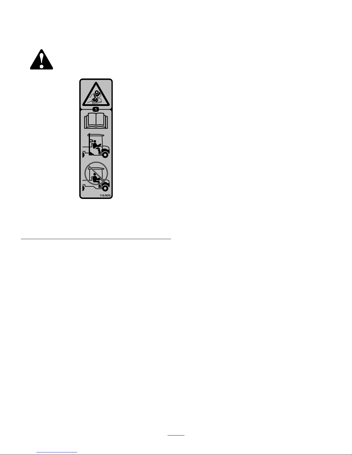
decal115-7670
115-7670
1.Crushinghazard,rollover—readtheOperator’sManual;
ROPSmustbeinstalledforeffectiverolloverprotection;the
canopyalonedoesnotprotectincaseofarollover.
2
Page 3
Installation
LooseParts
Usethechartbelowtoverifythatallpartshavebeenshipped.
Description
Qty.
Use
Nopartsrequired
–
Preparethemachine.
Rearsupporttube1
Left,rearsupportbracket
1
Right,rearsupportbracket1
Bolt(5/16x2-3/4inches)
8
Bolt(5/16x2inches)
2
Bolt(5/16x1-3/4inches)
4
Flatwasher(5/16inch)
10
Flangenut(5/16inch)
25
Bolt(5/16x1inch)
10
Rightdash-supportbracket1
Carriagebolt(5/16x3/4inch)
2
Flatwasher(3/8inch)
2
Bolt(3/8x1inch)—machineswithROPSonly
2
Clinchnuts—machineswithROPSonly
2
Hex-socketbuttonheadscrew(5/16x2
inches)—2016andaftermodelsonly
1
Spacer—2016andaftermodelsonly
1
Flatwasher(11/32inch)—2016andafter
modelsonly
1
Locknut(5/16inch)—2016andaftermodels
only
1
Installthecanopy.
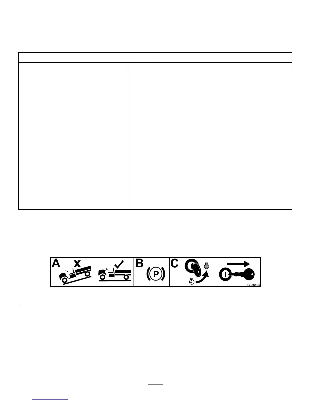
PreparingtheMachine
1.Parkthemachineonalevelsurface.
2.Engagetheparkingbrake.
3.Shutofftheengineandremovethekeyfromthekeyswitch.
g038494
Figure1
3
Page 4

InstallingtheCanopy
1.Ifyourmachineisequippedwitharolloverprtection
system(ROPS),youdonotneedtoinstallarear
supporttube;proceedtostep3.Ifyourmachineisnot
equippedwithaROPS,proceedasfollowstoinstall
therearsupporttube:
Note:MachineswithaROPSdoesnotusetheparts
describedinthefollowingsub-steps.
A.Looselyinstallthesupportbracketstotherear
supporttubeusing4bolts(5/16x2-3/4inches),
4bolts(5/16x1-3/4inches),4atwashers(5/16
inch),and8angenuts(5/16inch)asshownin
Figure2.
g009307
Figure2
Leftsideshown
1.Rearsupporttube
4.Bolt(5/16x2-3/4inches)
2.Left-siderearsupport
bracket
5.Bolt(5/16x1-3/4inches)
3.Flatwasher(5/16inch)6.Flangenut(5/16inch)
B.Looselyinstallthereartubeandsupport-bracket
assembliestothemachineusing8bolts(5/16x
1inch)and8angenuts(5/16inch)asshown
inFigure3.
G009288
1
2
3
4
4
5
6
g009288
Figure3
Leftsideshown
1.Left,frontsupport4.Bolt(5/16x1inch)
2.Rearsupporttube
(assembled)
5.Flangenut(5/16inch)—for
theleftsideitisexisting;
fortherightsideitisa
loosepart
3.Flangenut(5/16inch)6.Carriagebolt(5/16x3/4
inch)
2.Installtheleft,frontsupporttubetothemachineas
showninFigure3.
4
Page 5

3.Locatetheexistingbracketmountedtothecrosstube
andundertherightsideofthedash,andremovethe
bracketunderthedash(Figure4).
Note:Retainthehardware.
G009567
1
2
3
3
7
3
2
4
5
3
6
g009567
Figure4
Rightsideofthedashshown;2015andBeforeModelsOnly
1.Bracket(existing)5.Right,frontsupport-tube
assembly
2.Bolt(existing)6.Dashbolt(5/16x1inch)
3.Nut(existing)7.Flangenut(5/16inch)
4.Dash-supportbracket
(loose)
4.For2015andBeforeModelsonly,assemblethenew
dashsupportbrackettothemachinebyperforming
thefollowingprocedure:
A.Installthedashbolt(5/16x1inch)throughthe
right,frontsupporttube,dash,anddashbracket
(Figure4).
B.Looselyinstalltheangenut(5/16inch)tosecure
thedashbracketandsupporttubetothemachine
(Figure4).
C.Looselyinstalltheremainingpreviously-removed
hardwaretosecurethedashbrackettothecross
tubeandframe(Figure4).
5.For2016andAfterModelsonly,securethecanopy
supporttothedashsupportasfollows:
A.Installthespacerandatwasher(11/32inch)
betweenthedashanddashsupport(Figure5).
B.Installthehex-socketbuttonheadscrew(5/16x
2inches)throughthecanopysupport,dash,and
dashsupport(Figure5).
C.Installtheangenut(5/16inch)tosecurethe
dashsupporttothecanopysupport(Figure5).
g199154
Figure5
2016andAfterModelsOnly
1.Hex-socketbuttonhead
screw(5/16x2inches)
4.Spacer
2.Dashsupport
5.Locknut(5/16inch)
3.Flatwasher(1 1/32inch)6.Canopysupport
5
Page 6

6.Removetherearboltandnutthatsecurethedashto
thefrontframesupportontheleftsideofthemachine
(Figure3).
Note:Retaintherearboltandnut.
7.Looselyinstallthefrontsupportstotheoorofthe
machine(Figure3).
Important:Ontheleftside,usetheexistingnut
justremovedandbolt(5/16x1inch).
Ontherightside,useabolt(5/16x1inch)and
angenut(5/16inch)fromlooseparts.Securethe
bottomofbothtubestothemachineoorusing
thecarriagebolts(5/16x3/4inch)andange
nuts(5/16inch).
8.Locatethecanopytopinloosepart.Locateand
removetheassembledclinchnut,washer,andbolt
securingtherearcrossbaroftheinternalcanopyframe
tothecanopy.Retainthesepartsforinstallingthe
canopytoptotherearsupportframes.
9.IfyourmachinehasaROPS,mounttheclinchnuts
intotheholesintheROPS(Figure8).
10.Liftthecanopyontothesupportframe,andloosely
installthecanopytothefrontsupportsusing4screws
(5/16x2-3/4inches),4atwashers(5/16inch),and4
angenuts(5/16inch)asshowninFigure6.
Note:Thecanopysupportisalreadylooselyinstalled
tothecanopy(Figure6).
G009289
2
5
1
4
3
5
6
g009289
Figure6
1.Canopy4.Screw(5/16x2-3/4
inches)andwasher(5/16
inch)
2.Right,frontsupport5.Flangenut(5/16inch)
3.Left,frontsupport6.Canopysupport
11.Securethecanopytotherearsupportframeasfollows:
A.IfyourmachinedoesnothaveaROPS,securethe
canopytotherearsupporttubeusing2screws
(5/16x2inches),2washers(5/16inch),and2
angenuts(5/16inch)asshowninFigure7.
G009291
1
2
3
4
g009291
Figure7
MachinewithoutaROPS
1.Rearsupporttube
3.Bolt(5/16x2inches)and
washer(5/16inch)
2.Canopy4.Flangenut(5/16inch)
B.IfyourmachinedoeshaveaROPS,securethe
canopytotheROPSframeusing2bolts(3/8x1
inch)and2atwashers(3/8inch)intheclinch
nutsinstalledpreviously(Figure8).
G009290
1
2
3
4
g009290
Figure8
MachinewithaROPS
1.ROPS3.Canopy
2.Clinchnut4.Bolt(3/8x1inch)and
washer(3/8inch)
12.Startingatthebottomofthemachineandworking
yourwaytothetop,tightenallthefasteners.
6
Page 7

Notes:
Page 8

 Loading...