

Page 1
Form No. 3356-406 Rev A
G004117
Workman® e2060 and e2065
Utility Vehicles
Model No. 07287TC —Serial No. 270000001 and Up
Model No. 07288TC —Serial No. 270000001 and Up
Register your product at www.Toro.com Original Instructions (EN)
Page 2
Introduction
R ead this infor mation carefully to lear n ho w to
operate and maintain y our product properly and
to a v oid injur y and product damag e . Y ou are
responsible for operating the product properly
and safely .
Y ou ma y contact T oro directly at www .T oro .com
for product and accessor y infor mation, help
finding a dealer , or to register y our product.
W henev er y ou need ser vice , g en uine T oro par ts ,
or additional infor mation, contact an A uthorized
Ser vice Dealer or T oro Customer Ser vice and ha v e
the model and serial n umbers of y our product
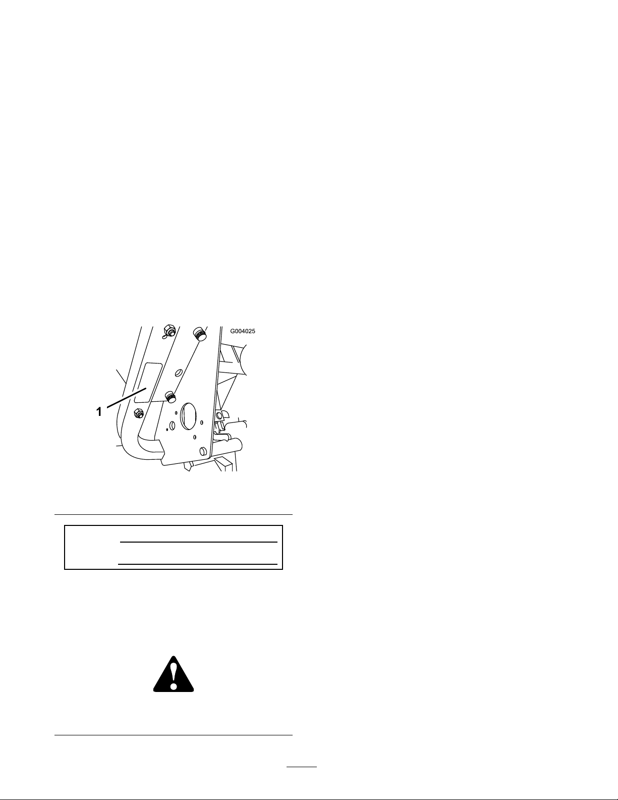
ready . Figure 1 identifies the location of the model
and serial n umbers on the product. W rite the
n umbers in the space pro vided.
T his man ual uses 2 other w ords to highlight
infor mation. Impor tant calls attention to special
mec hanical infor mation and Note emphasizes
g eneral infor mation w or th y of special attention.
Figure 1
1. Model and serial number location
Model No.
Serial No.
T his man ual identifies potential hazards and has
safety messag es identified b y the safety aler t
symbol ( Figure 2 ), whic h signals a hazard that ma y
cause serious injur y or death if y ou do not follo w
the recommended precautions .
Figure 2
1. Safety alert symbol
© 2006—The Toro® Company
8111 Lyndale Avenue South
Bloomington, MN 55420
Contact us at www.Toro.com.
2
Printed in the USA.
All Rights Reserved
Page 3

Contents
Introduction . . . . . . . . . . . . . . . . . . . . . . . . . . . . . . . . . . . . . . . . . . . . . . . . . . . . . . . 2
Safety . . . . . . . . . . . . . . . . . . . . . . . . . . . . . . . . . . . . . . . . . . . . . . . . . . . . . . . . . . . . . . . . . . 4
Safe Operating Practices . . . . . . . . . . . . . . . . . . . . . . 4
Before Operating . . . . . . . . . . . . . . . . . . . . . . . . . . . . . . . . . 4
Operation . . . . . . . . . . . . . . . . . . . . . . . . . . . . . . . . . . . . . . . . . . . . 4
Handling and Ser vicing
Batteries . . . . . . . . . . . . . . . . . . . . . . . . . . . . . . 7
General Maintenance . . . . . . . . . . . . . . . . . . . . . . . . . . . 8
Safety and Instr uctional Decals . . . . . . . . . . . . 9
Setup . . . . . . . . . . . . . . . . . . . . . . . . . . . . . . . . . . . . . . . . . . . . . . . . . . . . . . . . . . . . . . . . 12
1 Installing the R ear W heels . . . . . . . . . . . . . . . 12
2 Installing the F ront W heels . . . . . . . . . . . . . . 13
3 Installing the Steering W heel . . . . . . . . . . . 13
4 Installing the Bumper . . . . . . . . . . . . . . . . . . . . . . 14
5 Installing the Seats . . . . . . . . . . . . . . . . . . . . . . . . . . 14
6 Installing the Hitc h . . . . . . . . . . . . . . . . . . . . . . . . . 14
7 Installing the Batteries . . . . . . . . . . . . . . . . . . . . . 15
8 Installing the Carg o Bo x . . . . . . . . . . . . . . . . . . 17
9 Chec king the Tire Pressure . . . . . . . . . . . . . . 17
10 Setting the Charg er V oltag e . . . . . . . . . . . 18
11 Adjusting the F ront W heel
T oe-in . . . . . . . . . . . . . . . . . . . . . . . . . . . . . . . 18
12 R eading the Man ual and Viewing
the Safety Video . . . . . . . . . . . . . . . . . 19
Product Ov er view . . . . . . . . . . . . . . . . . . . . . . . . . . . . . . . . . . . . . . . . . . . . . 20
Controls . . . . . . . . . . . . . . . . . . . . . . . . . . . . . . . . . . . . . . . . . . . 20
Specifications . . . . . . . . . . . . . . . . . . . . . . . . . . . . . . . . . . . 23
Operation . . . . . . . . . . . . . . . . . . . . . . . . . . . . . . . . . . . . . . . . . . . . . . . . . . . . . . . . . . 24
T hink Safety First . . . . . . . . . . . . . . . . . . . . . . . . . . . . . . 24
Pre-Star ting Chec ks . . . . . . . . . . . . . . . . . . . . . . . . . . . 24
Chec king the Tire Pressure . . . . . . . . . . . . . . . . . 24
Operating the V ehicle . . . . . . . . . . . . . . . . . . . . . . . . 24
Stopping the V ehicle . . . . . . . . . . . . . . . . . . . . . . . . . . 24
P arking the V ehicle . . . . . . . . . . . . . . . . . . . . . . . . . . . . 24
Understanding and Using the
Batter y System . . . . . . . . . . . . . . . . . . . 24
Operating the Carg o Bo x . . . . . . . . . . . . . . . . . . . 26
Breaking in a New V ehicle . . . . . . . . . . . . . . . . . . 27
Loading the Carg o Bo x . . . . . . . . . . . . . . . . . . . . . . 27
T ranspor ting the V ehicle . . . . . . . . . . . . . . . . . . . . 27
T o wing the V ehicle . . . . . . . . . . . . . . . . . . . . . . . . . . . . 28
T o wing a T railer . . . . . . . . . . . . . . . . . . . . . . . . . . . . . . . . . 28
Maintenance . . . . . . . . . . . . . . . . . . . . . . . . . . . . . . . . . . . . . . . . . . . . . . . . . . . . . . 29
R ecommended Maintenance
Sc hedule(s) . . . . . . . . . . . . . . . . . . . . . . . . . . . . . . . 29
Daily Maintenance Chec klist . . . . . . . . . . . . . . 30
Premaintenance Procedures . . . . . . . . . . . . . . . . . . . . . . . 30
Hea vy Duty Operation . . . . . . . . . . . . . . . . . . . . . . 30
J ac king the V ehicle . . . . . . . . . . . . . . . . . . . . . . . . . . . . . 31
Lubrication . . . . . . . . . . . . . . . . . . . . . . . . . . . . . . . . . . . . . . . . . . . . . . . . 31
W here to Add Grease . . . . . . . . . . . . . . . . . . . . . . . . 31
Electrical System Maintenance . . . . . . . . . . . . . . . . . . . 32
Maintaining the Batteries . . . . . . . . . . . . . . . . . . . 32
R e placing the Fuses . . . . . . . . . . . . . . . . . . . . . . . . . . . 34
R e placing the Headlights . . . . . . . . . . . . . . . . . . . 34
Dri v e System Maintenance . . . . . . . . . . . . . . . . . . . . . . . . . 35
Inspecting the Tires . . . . . . . . . . . . . . . . . . . . . . . . . . . 35
Adjusting the F ront
Suspension . . . . . . . . . . . . . . . . . . . . . . . . 35
Adjusting F ront W heel T oe-In . . . . . . . . . . . 36
Chec king the T ransaxle Oil
Lev el . . . . . . . . . . . . . . . . . . . . . . . . . . . . . . . . . 37
Brak e Maintenance . . . . . . . . . . . . . . . . . . . . . . . . . . . . . . . . . . . . 37
Inspecting the Brak es . . . . . . . . . . . . . . . . . . . . . . . . . 37
Chec king the Brak e Fluid
Lev el . . . . . . . . . . . . . . . . . . . . . . . . . . . . . . . . . 37
Adjusting the P arking Brak e . . . . . . . . . . . . . . . 38
Cleaning . . . . . . . . . . . . . . . . . . . . . . . . . . . . . . . . . . . . . . . . . . . . . . . . . . . . 38
W ashing the V ehicle . . . . . . . . . . . . . . . . . . . . . . . . . . . 38
Storag e . . . . . . . . . . . . . . . . . . . . . . . . . . . . . . . . . . . . . . . . . . . . . . . . . . . . . . . . . . . . . . 39
T roubleshooting . . . . . . . . . . . . . . . . . . . . . . . . . . . . . . . . . . . . . . . . . . . . . . . . 40
Sc hematics . . . . . . . . . . . . . . . . . . . . . . . . . . . . . . . . . . . . . . . . . . . . . . . . . . . . . . . . 42
3
Page 4

Safety
Improper use or maintenance b y the operator
or o wner can result in injur y . T o reduce the
potential for injur y , comply with these safety
instr uctions and alw a ys pa y attention to the safety
aler t symbol, whic h means Caution , W ar ning , or
Danger —“personal safety instr uction. ” F ailure to
comply with the instr uction ma y result in personal
injur y or death.
Super visors , operators , and ser vice persons should
be familiar with the follo wing standards and
publications (the material ma y be obtained from
the address sho wn):
SAE J2258 Light Utility V ehicle
SAE Inter national, 400 Commonw ealth Dri v e ,
W ar rendale , P A 15096-0001 U .S .A.
Safe Operating Practices
T he W or kman is an of f-highw ay v ehicle
onl y and is not designed, equipped, or
man uf actur ed f or use on public str eets,
r oads, or highw ays.
Supervisor’s Responsibilities
• Mak e sure that operators are thoroughly
trained and familiar with the Operator’ s Manual
and all labels on the v ehicle .
• Be sure to establish y our o wn special
procedures and w ork r ules for un usual
operating conditions (e .g . slopes too stee p for
v ehicle operation).
Note: T his v ehicle has a super visor speed limit
switc h to allo w y ou to limit the maxim um speed
that the operator can dri v e the v ehicle . R efer
to Super visor Speed Limit Switc h section in
Operation , pag e 24 .
Before Operating
• Operate the v ehicle only after reading and
understanding the contents of this man ual.
• Nev er allo w c hildren to operate the v ehicle .
Any one who operates the v ehicle should ha v e
a motor v ehicle license .
• Nev er allo w other adults to operate the v ehicle
without first reading and understanding the
Operator’ s Manual . Only trained and authorized
persons should operate this v ehicle . Mak e sure
that all operators are ph ysically and mentally
capable of operating the v ehicle .
• T his v ehicle is designed to car r y only y ou,
the operator , and one passeng er in the seat
pro vided b y the man ufacturer . Nev er car r y
any other passeng ers on the v ehicle .
• Nev er operate the v ehicle when under
the influence of dr ugs or alcohol. Ev en
prescription dr ugs and cold medicines can
cause dro wsiness .
• Do not dri v e the v ehicle when y ou are tired.
Be sure to tak e occasional breaks . It is v er y
impor tant that y ou sta y aler t at all times .
• Become familiar with the controls and kno w
ho w to stop the v ehicle quic kly .
• K ee p all shields , safety devices , and decals in
place . If a shield, safety device , or decal is
malfunctioning, illegible , or damag ed, re pair or
re place it before operating the v ehicle .
• Alw a ys w ear substantial shoes . Do not operate
the v ehicle while w earing sandals , tennis shoes
or sneak ers . Do not w ear loose fitting clothing
or jew elr y whic h could g et caught in mo ving
par ts and cause personal injur y .
• W earing safety glasses , safety shoes , long pants
and a helmet is advisable and required b y some
local safety and insurance regulations .
• A v oid dri ving when it is dark, especially in
unfamiliar areas . If y ou m ust dri v e when it
is dark, be sure to dri v e cautiously , use the
headlights , and ev en consider adding additional
lights .
• Be extremely careful when operating around
people . Alw a ys be a w are of where b ystanders
might be .
• Before operating the v ehicle , alw a ys c hec k the
designated areas of the v ehicle that are stated
in the pre-star ting section of this man ual. If
something is wrong, do not use the v ehicle .
Mak e sure that the problem is cor rected before
the v ehicle or attac hment is operated.
Operation
• T he operator and passeng er should remain
seated whenev er the v ehicle is in motion.
4
Page 5

T he operator should k ee p both hands on the
steering wheel whenev er possible , and the
passeng er should use the hand holds pro vided.
K ee p y our ar ms and legs within the v ehicle
body at all times .
• Dri v e slo w er and tur n less shar ply when y ou
are car r ying a passeng er . R emember y our
passeng er ma y not be expecting y ou to brak e
or tur n and ma y not be ready .
• Alw a ys w atc h out for and a v oid lo w o v erhangs
suc h as tree limbs , door jambs , and o v er -head
w alkw a ys . Mak e sure there is enough room
o v er head to easily clear the v ehicle and y our
head.
• F ailure to operate the v ehicle safely ma y result
in an accident, tip o v er of the v ehicle , and
serious injur y or death. Dri v e carefully . T o
prev ent tipping or loss of control:
– Use extreme caution, reduce speed, and
maintain a safe distance around sand traps ,
ditc hes , creeks , ramps , unfamiliar areas ,
or any areas that ha v e abr upt c hang es in
g round conditions or elev ation.
– W atc h for holes or other hidden hazards .
– Use extra caution when operating the
v ehicle on w et surfaces , in adv erse w eather
conditions , at higher speeds , or with a
full load. Stopping time and distance will
increase with a full load.
– A v oid sudden stops and star ts . Do not
g o from rev erse to forw ard or forw ard to
rev erse without first coming to a complete
stop .
– Slo w do wn before tur ning . Do not attempt
shar p tur ns or abr upt maneuv ers or other
unsafe dri ving actions that ma y cause a loss
of v ehicle control.
– W hen dumping, do not let any one stand
behind the v ehicle and do not dump the
load on any one’ s feet. R elease the tailg ate
latc hes from the side of the bo x, not from
behind.
– Only operate the v ehicle when the carg o
bo x is do wn and latc hed.
– Before bac king up , look to the rear and
ensure that no one is behind y ou. Bac k up
slo wly .
– W atc h out for traffic when y ou are near or
crossing roads . Alw a ys yield the right of
w a y to pedestrians and other v ehicles . T his
v ehicle is not designed for use on streets or
highw a ys . Alw a ys signal y our tur ns or stop
early enough so that other people kno w
what y ou plan to do . Obey all traffic r ules
and regulations .
– T he electrical system of the v ehicle
can produce sparks capable of igniting
explosi v e materials . Nev er operate the
v ehicle in or near an area where there is
dust or fumes in the air whic h are explosi v e .
– If y ou are ev er unsure about safe operation,
stop w or k and ask y our super visor .
• If the v ehicle ev er vibrates abnor mally , stop
immediately , w ait for all motion to stop , and
inspect the v ehicle for damag e . R e pair all
damag e before commencing operation.
• Before g etting off of the seat:
1. Stop the mo v ement of the v ehicle .
2. Set the parking brak e .
3. T ur n the k ey to Off .
4. R emo v e the k ey .
Note: If the v ehicle is on an incline , bloc k
the wheels after g etting off of the v ehicle .
Braking
• Slo w do wn before y ou approac h an obstacle .
T his gi v es y ou extra time to stop or tur n a w a y .
Hitting an obstacle can damag e the v ehicle and
its contents . More impor tant, it can injure y ou
and y our passeng er .
• Gross V ehicle W eight (GVW) has a major
impact on y our ability to stop and/or tur n.
Hea vy loads and attac hments mak e a v ehicle
harder to stop or tur n. T he hea vier the load,
the long er it tak es to stop .
• Decrease the v ehicle speed if the carg o bo x has
been remo v ed and there is no attac hment on
the v ehicle . T he braking c haracteristics c hang e
and fast stops ma y cause the rear wheels to loc k
up , whic h ma y affect the control of the v ehicle .
• T urf and pa v ement are m uc h more slipper y
when they are w et. It can tak e 2 to 4 times
as long to stop on w et surfaces as on dr y
surfaces . If y ou dri v e through standing w ater
dee p enough to g et the brak es w et, they will
not w ork w ell until they are dr y . After dri ving
through w ater , y ou should test the brak es to
5
Page 6

mak e sure they w ork properly . If they do not,
dri v e slo wly while putting light pressure on the
brak e pedal. T his will dr y the brak es out.
Operating on Hills
Operating the v ehicle on a hill may cause
tipping or r olling of the v ehicle, or the motor
may stall and y ou could lose head w ay on the
hill. T his could r esult in per sonal injur y .
• Do not operate on ex cessi v el y steep
slopes.
• Do not accelerate quickl y or slam on
the brak es when backing do wn a hill,
especiall y with a load.
• If the batteries r un lo w or y ou lose
head w ay on a hill, slo wl y back straight
do wn the hill. Nev er attempt to tur n the
v ehicle ar ound.
• Operate the v ehicle slo wl y on a hill and
use caution.
• A v oid tur ning on a hill.
• R educe y our load and the speed of the
v ehicle.
• A v oid stopping on hills, especiall y with
a load.
T hese extra cautions need to be tak en when
operating the v ehicle on a hill:
• Slo w do wn before star ting up or do wn a hill.
• If the batteries r un lo w or y ou begin to lose
headw a y while climbing a hill, g radually apply
the brak es and slo wly bac k straight do wn the
hill.
• T ur ning while tra v eling up or do wn hills can
be dang erous . If y ou ha v e to tur n while on a
hill, do it slo wly and cautiously . Nev er mak e
shar p or fast tur ns .
• Hea vy loads affect stability . R educe the w eight
of the load and y our speed when operating on
hills or if the load has a high center of g ra vity .
Secure the load to prev ent it from shifting and
tak e extra care when hauling loads that shift
easily (liquid, roc k, sand, etc .).
• A v oid stopping on hills , especially with a load.
Stopping while g oing do wn a hill will tak e
long er than stopping on lev el g round. If the
v ehicle m ust be stopped, a v oid sudden speed
c hang es , whic h ma y initiate tipping or rolling
of the v ehicle . Do not slam on the brak es
when rolling bac kw ard, as this ma y cause the
v ehicle to o v er tur n.
• W e strongly recommend installing the optional
R OPS Kit when operating on hilly ter rain.
Operating on Rough Terrain
R educe speed and load when operating on rough
ter rain, unev en g round, and near curbs , holes , and
other sudden c hang es in ter rain. Loads ma y shift,
causing the v ehicle to become unstable .
W e strongly recommend installing the optional
R OPS Kit when operating on rough ter rain.
Sudden changes in ter rain may cause a br upt
steering wheel mo v ement, possibl y r esulting
in hand and ar m injuries.
• R educe y our speed when operating on
r ough ter rain and near curbs.
• Grip the steering wheel loosel y ar ound
the perimeter . K eep y our hands clear of
the steering wheel spok es.
Loading and Dumping
T he w eight and position of the carg o and
passeng er can c hang e the v ehicle center of g ra vity
and v ehicle handling . T o a v oid loss of control and
personal injur y , follo w these guidelines:
• Do not car r y loads whic h ex ceed the load
limits described on the v ehicle w eight label;
refer to Specifications in Product Ov er view ,
pag e 20 , for v ehicle w eight limits . T he load
rating is for lev el surf aces onl y .
• R educe the w eight of the load when operating
on hills and rough ter rain to a v oid tipping or
o v er tur ning of the v ehicle .
• R educe the w eight of the load if the center of
g ra vity is high. Items suc h as bric ks , fer tilizer ,
or landscape timbers stac k higher in the bo x.
T he higher a load is stac k ed, the more lik ely
the v ehicle is to tip o v er . Distribute the load as
lo w as possible , making sure that the load does
not affect rear visibility .
6
Page 7

• P osition the w eight of the load ev enly from
side to side . If y ou position the load to w ard
one of the sides , the v ehicle is more lik ely to
tip o v er while tur ning .
• P osition the w eight of a load ev enly from front
to bac k. If y ou position the load behind the
rear axle , it will reduce the w eight on the front
wheels . T his ma y result in a loss of steering
control or cause the v ehicle to tip o v er on hills
or bumpy ter rain.
• Use extra caution if the load ex ceeds the
dimensions of the bo x and when handling
off-center loads that cannot be centered. K ee p
loads balanced and secure to prev ent them
from shifting .
• Alw a ys secure loads so that they do not shift.
If a load is not secured, or y ou are transpor ting
a liquid in a larg e container suc h as a spra yer ,
the load can shift. T his shifting happens most
often while tur ning, g oing up or do wn hills ,
suddenly c hanging speeds , or while dri ving
o v er rough surfaces . Shifting loads can cause
the v ehicle to tip o v er .
T he w eight of the bo x may be hea vy .
Hands or other body par ts could be
cr ushed.
Handling and Servicing
Batteries
• T o reduce the potential for fire , k ee p the
batteries and motor area free of ex cessi v e
g rease , g rass , lea v es , and accum ulation of dir t.
• Alw a ys disconnect and remo v e a batter y cable
before ser vicing any electrical components .
• Disconnecting any batter y cable will inhibit
operation of the electrical system.
• Batter y electrolyte contains sulfuric acid.
Sulfuric acid produces h y drog en g as whic h, in
the right propor tions is explosi v e .
– Alw a ys ser vice , store , and c harg e the
v ehicle in a w ell v entilated area.
– K ee p sparks and open flames a w a y from
the batteries .
– Do not smok e near the batteries .
– Nev er use an open flame to c hec k the lev el
or leakag e of batter y electrolyte .
• Use caution when handling and w orking
around electrolyte . T he sulfuric acid in
electrolyte can bur n skin and damag e clothing .
Fur ther more , it can be emitted as a g as that
can damag e y our lungs .
– W ear proper eye , hand, and face protection.
– K eep hands and other body par ts
clear when lo w ering the bo x.
– Do not dump materials on bystander s.
• Nev er dump a loaded carg o bo x while the
v ehicle is sidew a ys on a hill. T he c hang e in
w eight distribution ma y cause the v ehicle to
o v er tur n.
• W hen operating with a hea vy load in the carg o
bo x, reduce y our speed and allo w for sufficient
braking distance . Do not suddenly apply the
brak es . Use extra caution on slopes .
• Be a w are that hea vy loads increase y our
stopping distance and reduce y our ability to
tur n quic kly without tipping o v er .
• T he rear carg o space is intended for load
car r ying pur poses only , not for passeng ers .
• Nev er o v erload y our v ehicle . T he decal
(located on the rear frame) sho ws load limits
for the v ehicle . Nev er o v erload the attac hments
or ex ceed the Gross V ehicle W eight (GVW).
– Do not lean o v er the batteries at any time .
– A v oid breathing batter y fumes .
– Fill the batteries where clean w ater is alw a ys
a v ailable for flushing the skin.
– If y ou g et electrolyte on y our skin or eyes ,
flush the affected area for 20 min utes with
clean w ater . R emo v e acid soak ed clothing .
Seek medical attention immediately .
– K ee p c hildren and pets a w a y from the
batteries and electrolyte .
• Electrolyte is v er y poisonous .
– Do not drink electrolyte .
– If electrolyte is sw allo w ed, do not induce
v omiting; instead, drink larg e amounts of
w ater or milk follo w ed b y milk of magnesia,
beaten ra w eg gs , or v eg etable oil. Get
medical attention immediately .
– K ee p c hildren and pets a w a y from the
batteries and electrolyte .
7
Page 8

• W hen not filling the batteries , k ee p the batter y
v ent caps tight on the batteries . Nev er operate
the v ehicle if any of the v ent caps are missing
or damag ed.
• W hen remo ving or installing the batteries , do
not allo w the batter y ter minals to touc h any
metal par ts of the v ehicle .
• Do not allo w metal tools to shor t betw een
the batter y ter minals and metal par ts of the
v ehicle . R emo v e all jew elr y and w atc hes before
ser vicing the batteries .
• Do not c hec k a batter y c harg e b y placing a
metal object across the posts . T his will cause
sparks whic h can cause an explosion.
• Alw a ys k ee p the batter y retainers in place to
protect and secure the batteries .
• R ead and understand the c harging instr uctions
before c harging the batteries; refer to Charging
the Batteries in Maintenance , pag e 29 . Also ,
tak e the follo wing precautions and actions
when c harging the batteries:
– T ur n the v ehicle On/Off switc h to Off
before connecting the c harg er to a po w er
source .
– Use only the batter y c harg er supplied with
the v ehicle to c harg e the batteries .
– Do not c harg e a damag ed or frozen batter y .
– Alw a ys unplug the A C po w er cord from the
po w er outlet before unplug ging it from the
v ehicle c harging rece ptacle to a v oid sparks .
– If during c harging a batter y g ets hot, begins
emitting larg e amounts of g asses , or spews
electrolyte , immediately disconnect the
c harg er po w er cord from the po w er outlet.
Ha v e the v ehicle ser viced b y an A uthorized
Ser vice Dealer before using it ag ain.
• Do not use open pans of fuel or flammable
cleaning fluids for cleaning par ts .
• If major re pairs are ev er needed or assistance
is required, contact an A uthorized T oro
Distributor .
• T o be sure of optim um perfor mance and safety ,
alw a ys purc hase g en uine T oro re placement
par ts and accessories . R e placement par ts and
accessories made b y other man ufacturers
could be dang erous . Altering this v ehicle in
any manner that ma y affect v ehicle operation,
perfor mance , durability , or its use , ma y result
in injur y or death. Suc h use could v oid the
product w ar ranty .
General Maintenance
• Only qualified and authorized personnel shall
be per mitted to maintain, re pair , adjust, or
inspect the v ehicle .
• Before ser vicing or making adjustments to the
v ehicle , stop the v ehicle , set the parking brak e ,
and remo v e the k ey to prev ent someone from
accidentally star ting it.
• T o mak e sure that the entire v ehicle is in g ood
condition, k ee p all n uts , bolts , and screws
properly tightened.
8
Page 9
Safety and Instructional
Decals
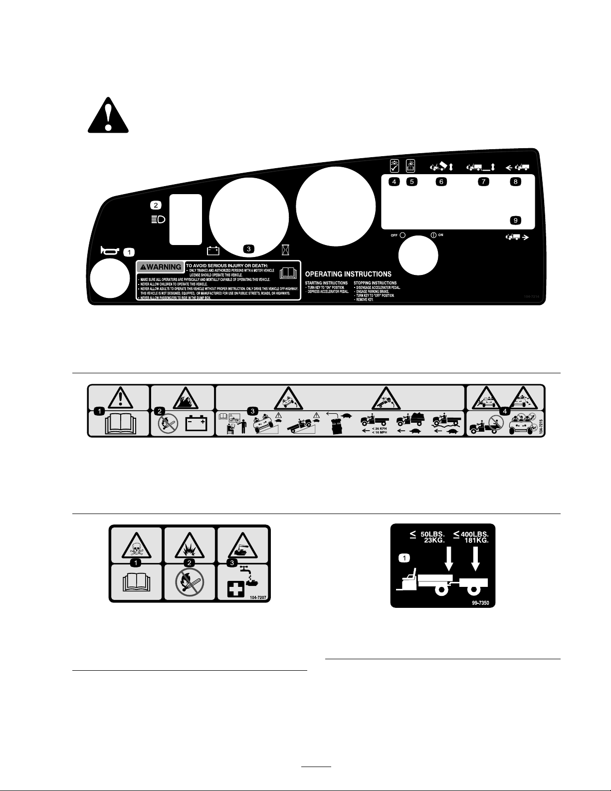
Safety decals and instr uctions are easily visible to the operator and are located near any
area of potential dang er . R e place any decal that is damag ed or lost.
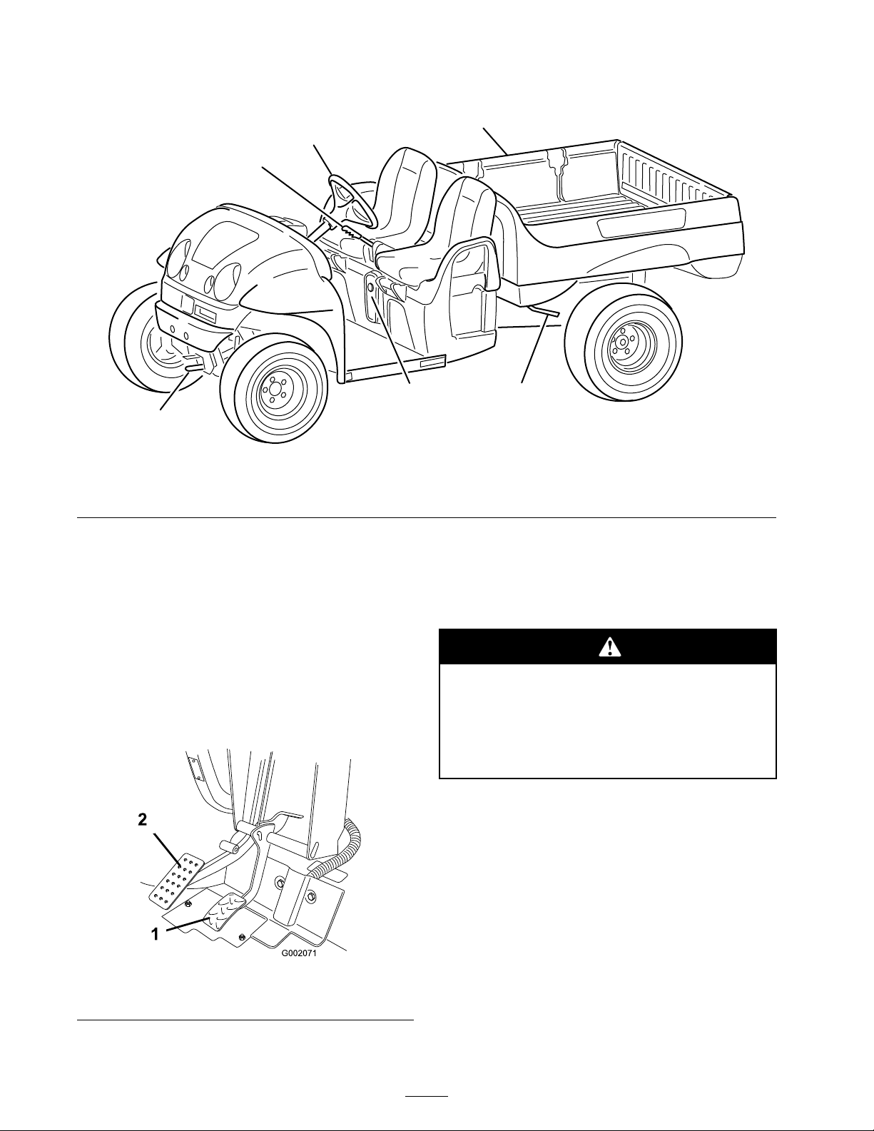
1. Horn
2. Headlights
3. Battery/hour meter 6. Cargo bed lift
4. Light on, OK 7. Rear lift
5. Light blinking, read the Operator’s
Manual.
104-7214
8. Forward
9. Reverse
104–7215
1. Warning—read the Operator’s Manual.
2. Explosion hazard—no re, open ames, or smoking around batteries.
3. Tipping hazard—receive training before operating the machine, use caution and drive slowly while on slopes; drive slowly when
turning, keep the vehicle speed under 16 MPH (26 km/h) when carrying a full or heavy load and when driving on rough terrain.
4. Falling and arm/leg injury hazards—do not carry passengers in the cargo bed and keep arms and legs inside of the vehicle at all times.
104-7207
1. Poison hazard—read the Operator’s Manual.
2. Explosion hazard—no re, open ames, or smoking.
3. Caustic liquid/chemical burn hazard—to perform rst aid,
ush with water.
1. Maximum tongue weight is 50 lb. (23 kg); maximum trailer
weight is 400 lb. (181 kg).
99–7350
9
Page 10

112-3049
1. Read the Operator’s Manual.
2. The maximum combined operator and passenger weight is
400 lb (181 kg).
3. The maximum cargo weight is 800 lb (362 kg).
4. The base weight of the vehicle is 1500 lb (680 kg).
5. The maximum gross vehicle weight is 2700 lb (1225 kg).
107-0295
1. Warning—read the Operator’s Manual for more information
on batteries; batteries contain lead, do not discard;
disconnect the power cord from power source before
driving vehicle.
2. Explosion hazard—no re, open ames, or smoking; avoid
sparks.
107-0356
1. Warning—do not touch moving objects, fan; do not touch
the hot surfaces; read the Operator’s Manual.
107-0257
1. Battery schematic
99–7954
1. Warning—read the Operator’s Manual .
2. Falling hazard—do not carry passengers in the cargo bed.
3. Explosion hazard, static discharge into fuel container—do
not ll fuel containers in the cargo bed; place fuel containers
on the ground before lling.
10
Page 11
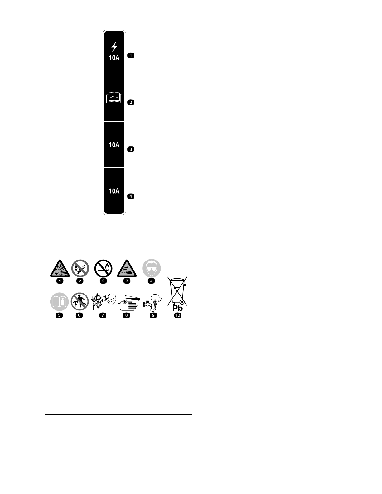
107-0287
1. Vehicle fuse, 10A
2. For fuse service, read the
Operator’s Manual.
3. Open, 10A
4. Accessory fuse, 10A
Battery Symbols
Some or all of these symbols are on your battery
1. Explosion hazard 6. Keep bystanders a safe
2. No re, open ame, or
smoking.
3. Caustic liquid/chemical
burn hazard
4. Wear eye protection
5. Read the Operator’s
Manual.
distance from the battery.
7. Wear eye protection;
explosive gases can cause
blindness and other injuries
8. Battery acid can cause
blindness or severe burns.
9. Flush eyes immediately
with water and get medical
help fast.
10. Contains lead; do not
discard.
11
Page 12

Setup
Loose Parts
Use the chart below to verify that all parts have been shipped.
Step
1
2
3
4
5
6
7
8
Wheel assembly
Wheel assembly
Steering wheel
Bumper 1
Seat 2
Hitch
Battery hold down
Battery hold down rod
Battery cables
Battery tray pads
Battery pad
Flange nut (3/8 inch)
Battery terminal protector spray
Cargo box
Right-hand pivot bracket
Left-hand pivot bracket
Flange head screw (3/8 x 1 inch)
Bolt (5/16 x 3/4 inch)
Flange nut (5/16 inch)
Description
Qty.
2
2
1
1
2
2
7
4
1
2
1
1
1
1
4
1
1
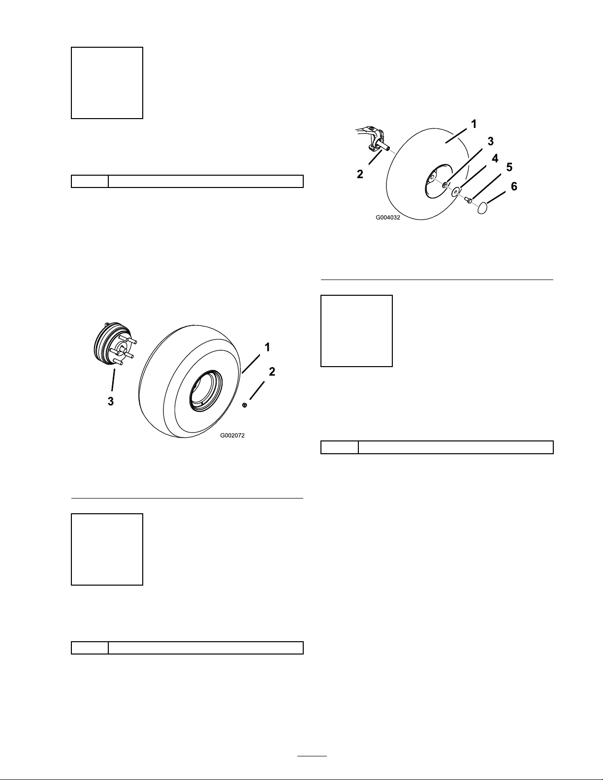
Install the rear wheels.
Install the front wheels.
Install the steering wheel.
Install the bumper.
Install the seats.
Install the hitch.
Install the batteries.
Install the cargo box.
Use
9
10
11
12
No parts required
No parts required
No parts required
Operator’s Manual
Parts Catalog
Safety Video
Registration Card
Predelivery Inspection Form
Key 2
Note: Deter mine the left and right sides of the
mac hine from the nor mal operating position.
–
–
–
1
1
1
1
1
12
Check the tire pressure.
Set the charger voltage.
Adjust the front wheel toe-in.
Read the Operator’s Manual and
watch the video before operating
the machine.
Page 13
Step
1
Installing the Rear Wheels
Parts needed for this step:
2
Wheel assembly
Procedure
1. R emo v e the fasteners securing the wheels .
2. R emo v e the shipping brac k et secured to the
wheel studs .
3. Mount the wheels with the previously remo v ed
fasteners ( Figure 3 ) and tor que to 45-65 ft-lb
(61-88 N ⋅ m).
3. Apply thread loc k er (blue) to the screw threads .
4. Mount the wheels with the previously remo v ed
fasteners ( Figure 4 ) and tor que the bolts to
135-165 ft-lb (183-224 N ⋅ m).
Figure 4
1. Tire and wheel assembly 4. Large washer
2. Spindle
3. Small washer
5. Screw
6. Dust cap
Step
Figure 3
1. Wheel assembly
2. Wheel nut
Step
2
Installing the Front Wheels
Parts needed for this step:
3. Wheel stud (rear wheel hub
shown)
3
Installing the Steering
Wheel
Parts needed for this step:
1
Steering wheel
Procedure
1. R emo v e the n ut and w asher from the steering
shaft.
2. Slide the steering wheel and w asher onto the
shaft. P osition the steering wheel on the shaft
so that the cross beam is horizontal when the
tires are pointed straight ahead and the thic k er
spok e of the steering wheel is do wnw ard.
3. Secure the steering wheel to the shaft with the
w asher and n ut ( Figure 5 ). T or que the n ut to
18-22 ft-lb (24-29 N ⋅ m)
2
Wheel assembly
Procedure
1. R emo v e the fasteners securing the wheels .
2. R emo v e the shipping brac k et from the spindles .
13
Page 14

Step
5
Installing the Seats
Parts needed for this step:
2 Seat
Figure 5
1. Steering wheel 3. Washer
2. Nut
4. Foam seal
Step
4
Installing the Bumper
Parts needed for this step:
1 Bumper
Procedure
1. R emo v e the 2 bolts , w ashers , and n uts secured
to the front of the frame .
2. Align the mounting holes and secure the
bumper to the frame with the fasteners
previously remo v ed ( Figure 6 ).
Procedure
Inser t the seat brac k et into the seat base opening
and pi v ot the seat do wnw ard ( Figure 7 ).
Figure 7
1. Seat bracket 2. Seat base
Figure 6
1. Bumper
14
Page 15

Step
Step
6
Installing the Hitch
Parts needed for this step:
1
Hitch
Procedure
1. R emo v e the 4 bolts and n uts from the inside
rear of the frame .
2. Align the hitc h with the mounting holes on the
frame . Secure the hitc h with the screws and
n uts ( Figure 8 ).
7
Installing the Batteries
Parts needed for this step:
2
Battery hold down
2
Battery hold down rod
7
Battery cables
4
Battery tray pads
1
Battery pad
2
Flange nut (3/8 inch)
1
Battery terminal protector spray
Procedure
T oro recommends the use of either T rojan T105
or T145, or US . Batter y US2200 or US145.
Batter y Specification: 6V 225AH @ 20hr rate
Dimensions: (LxWxH) (10-1/4 x 7-1/8 x 11-1/4
inc hes)
1. T ur n the k ey switc h to the Off position and
remo v e the k ey .
1. Hitch
2. Left pivot bracket
2. Install the batter y tra y pads into the rear frame
assembly as sho wn Figure 9 .
Figure 8
Figure 9
1. Battery tray pads
2. Rear frame assembly
15
Page 16
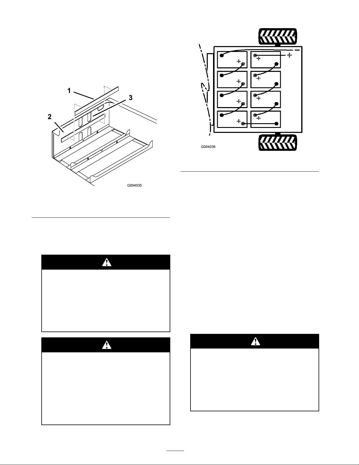
3. R emo v e the adhesi v e strip from the bac k of
the batter y pad and install it to the front inside
face of the rear frame as sho wn in Figure 10 .
Note: T he pad should be appro ximately 1/4
inc h belo w the bottom edg e of the upper set
of cut-out holes ( Figure 10 ).
Figure 10
1. Battery pad 3. Upper cut-out holes
2. Front inside face
4. Install the batteries as sho wn in Figure 11 .
Note: P a y attention to the batter y polarity
when installing the new batteries ( Figure 11 ).
Figure 11
5. Install the batter y retainers and tor que the n uts
to 150 to 200 in-lb (17 to 22 N ⋅ m).
6. Connect the batteries tog ether with the batter y
cables included in loose par ts , as sho wn in
Figure 11 . Ensure the cable routing does not
allo w cables to contact any shar p edg es .
Important: Check all high cur r ent
batter y connections to ensur e they ha v e
been pr oper l y secur ed.
Incor r ect batter y ca ble r outing could
dama ge the v ehicle and ca bles causing
spar ks. Spar ks can cause the batter y
gasses to explode, r esulting in per sonal
injur y .
Al w ays ensur e the batter y polarity when
making connections.
Batteries can gi v e y ou a po w erful
electrical shock.
• Use tools with plastic handles or
wrap the handles of metal tools with
electrical tape.
• Be car eful not to contact both a
positi v e ter minal and a negati v e
ter minal at the same time.
7. Tighten the bolt and secure the other side of
the clip with a new bolt (5/16 x 3/4 inc h) and
flang e n ut (5/16 inc h) ( Figure 11 ).
8. Connect the long, red, main positi v e lead
betw een the bank of batteries and the v ehicle
( Figure 11 ).
9. Connect the long, blac k, main neg ati v e lead
betw een the bank of batteries and the v ehicle
( Figure 11 ).
Loose or impr oper l y secur ed batter y
connections could dama ge the v ehicle
and ca bles causing spar ks. Spar ks can
cause the batter y gasses to explode,
r esulting in per sonal injur y .
Al w ays ensur e the batter y polarity when
making connections.
10. T or que the n uts securing all batter y cables to
120 to 180 inc h-lb (13.5 to 21 N ⋅ m).
16
Page 17
11. Coat the batter y ter minals with T oro batter y
ter minal protector .
12. Ensure that the r ubber boots on eac h batter y
cable are securely seated o v er the batter y
ter minals .
Step
8
Installing the Cargo Box
Parts needed for this step:
1
Cargo box
1
Right-hand pivot bracket
1
Left-hand pivot bracket
4
Flange head screw (3/8 x 1 inch)
1
Bolt (5/16 x 3/4 inch)
1
Flange nut (5/16 inch)
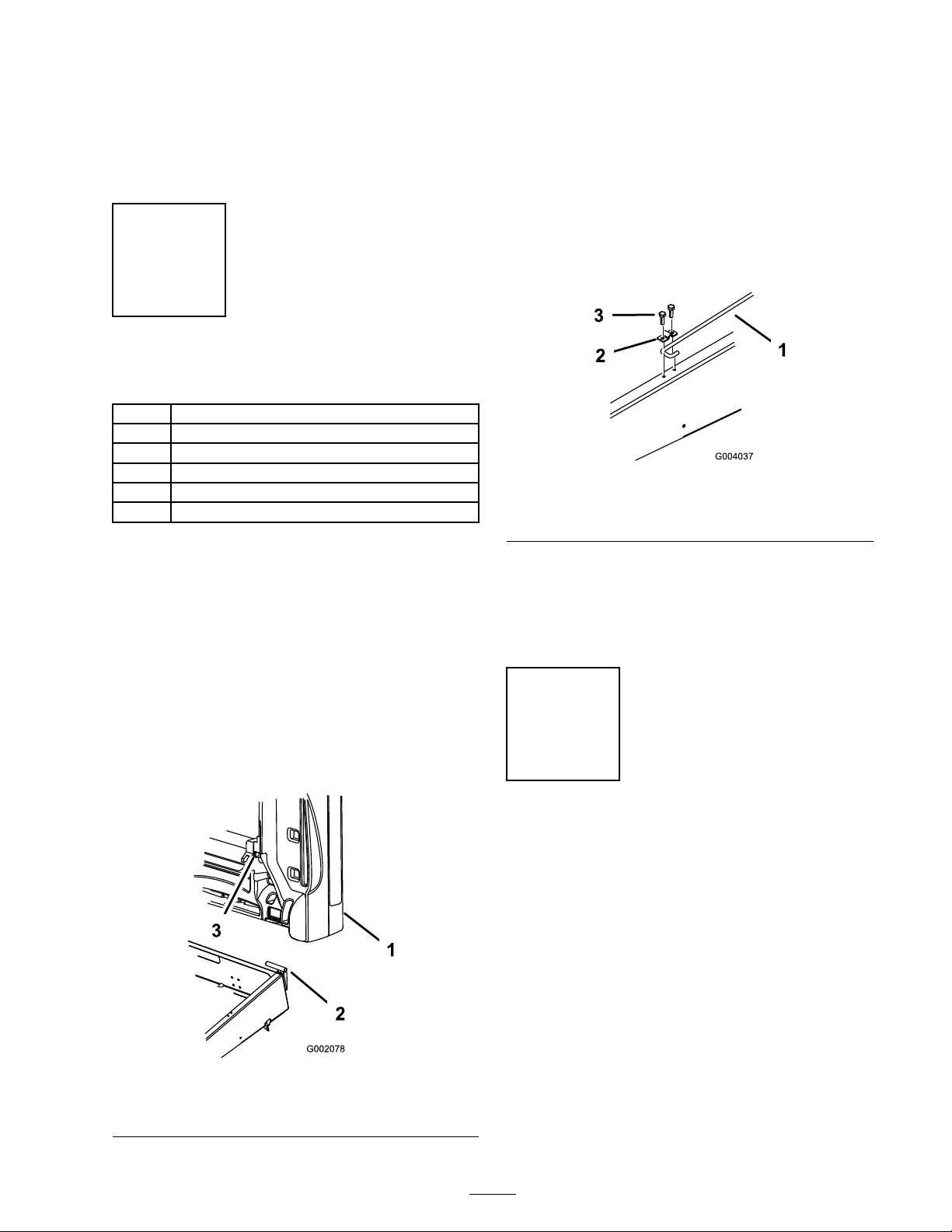
4. Inser t the right hand pi v ot brac k et into the
mounting hole in the carg o bo x and then
mount it to the frame . T or que the screws to
16 ft-lb (22 N ⋅ m).
5. Ha v e another person help to raise the carg o
bo x.
6. Loosen the bolt securing the prop rod clip to
the frame until y ou can slide the J-hook end of
the prop rod under the clip ( Figure 13 ).
Figure 13
1. Prop rod
2. Prop rod clip
3. Bolt (5/16 x 3/4 inch)
Procedure
1. P osition the carg o bo x onto the frame . T he
carg o bo x m ust la y flat and be centered.
2. Mount the left hand pi v ot brac k et to the left
rear cor ner of the frame with 2 flang e head
screws (3/8 x 1 inc h). T or que the screws to 16
ft-lb (22 N ⋅ m). P osition the brac k et as sho wn
in Figure 8 .
3. Slide the carg o bo x mounting hole onto the
pi v ot brac k et ( Figure 12 ).
7. Tighten the bolt and secure the other side of
the clip with a new bolt (5/16 x 3/4 inc h)
( Figure 13 ).
8. Lo w er the carg o bo x.
Step
9
Checking the Tire Pressure
No Parts Required
Procedure
Chec k the tire pressure ev er y 8 hours or daily to
ensure proper lev els .
T he air pressure rang e in the front and rear tires
is 8-22 psi (55-152 kP a).
Figure 12
1. Cargo box 3. Cargo box mounting hole
2. Pivot bracket
T he air pressure needed is deter mined b y the
pa yload car ried. Lo w er air pressure will pro vide
less compaction, a smoother ride , and few er tire
marks . Lo w er pressure should not be used for
hea vy pa yloads at high speeds .
17
Page 18

Higher pressures should be used for hea vier
220
200
100
120
G005241
pa yloads at higher speeds . Do not ex ceed the
maxim um pressure .
occur . Contact y our A uthorized T oro Dealer to
obtain the cor rect po w er cord if necessar y .
Step
10
Setting the Charger Voltage
No Parts Required
Procedure
Important: T he incor r ect v olta ge setting on
the batter y charger can impair function and
dama ge the charger .
Alw a ys mak e sure the c harg er v oltag e setting
matc hes the v oltag e used to po w er the c harg er .
1. Locate the v oltag e selector on the rear of the
c harg er ( Figure 14 ).
2. Adjust the v oltag e setting b y mo ving the switc h
on the v oltag e selector upw ard or do wnw ard
to c hang e the v oltag e setting ( Figure 14 ).
Step
11
Adjusting the Front Wheel
Toe-in
No Parts Required
Procedure
T he toe-in should be 1/8-5/8 inc h (3-16 mm) with
the follo wing parameters:
• T he tire pressure should be at 12 psi (83 kP a).
• T he ride height should be cor rect before
setting the toe-in; refer to the Adjusting the
F ront Suspension procedure in Maintenance ,
pag e 29 .
• T he v ehicle should be dri v en bac k and for th a
few times to relax the A-ar ms .
Figure 14
1. Voltage selector 3. Switch
2. Voltage setting window 4. Voltages by switch position
Adjust the v oltag e setting b y mo ving the switc h
on the v oltag e selector upw ard or do wnw ard to
c hang e the v oltag e setting
Alw a ys use the appropriate po w er cord for the
po w er outlet of the countr y or region c harging will
• Measure the toe-in with the wheels facing
straight ahead and a 175-225 lb (79-102 kg)
operator in the dri v er’ s seat.
Note: T he dri v er should dri v e up to the
measurement area and sta y seated in the v ehicle
while the measurement is being tak en.
If the v ehicle will be r un with medium to hea vy
loads most of the time , set the toe-in on the
high side of the recommended amount. If it
is g oing to be r un with a light load most of
the time , set the toe-in on the lo w side of the
recommended amount.
1. Measure the distance betw een both of the
front tires at the axle height at both the front
and rear of the front tires ( Figure 15 ). A fixture
or alignment g aug e is needed for the rear
measurement of the front tires at axle height.
Use the same fixture or alignment g aug e to
accurately measure the front of the front tires
at axle height ( Figure 15 ).
18
Page 19
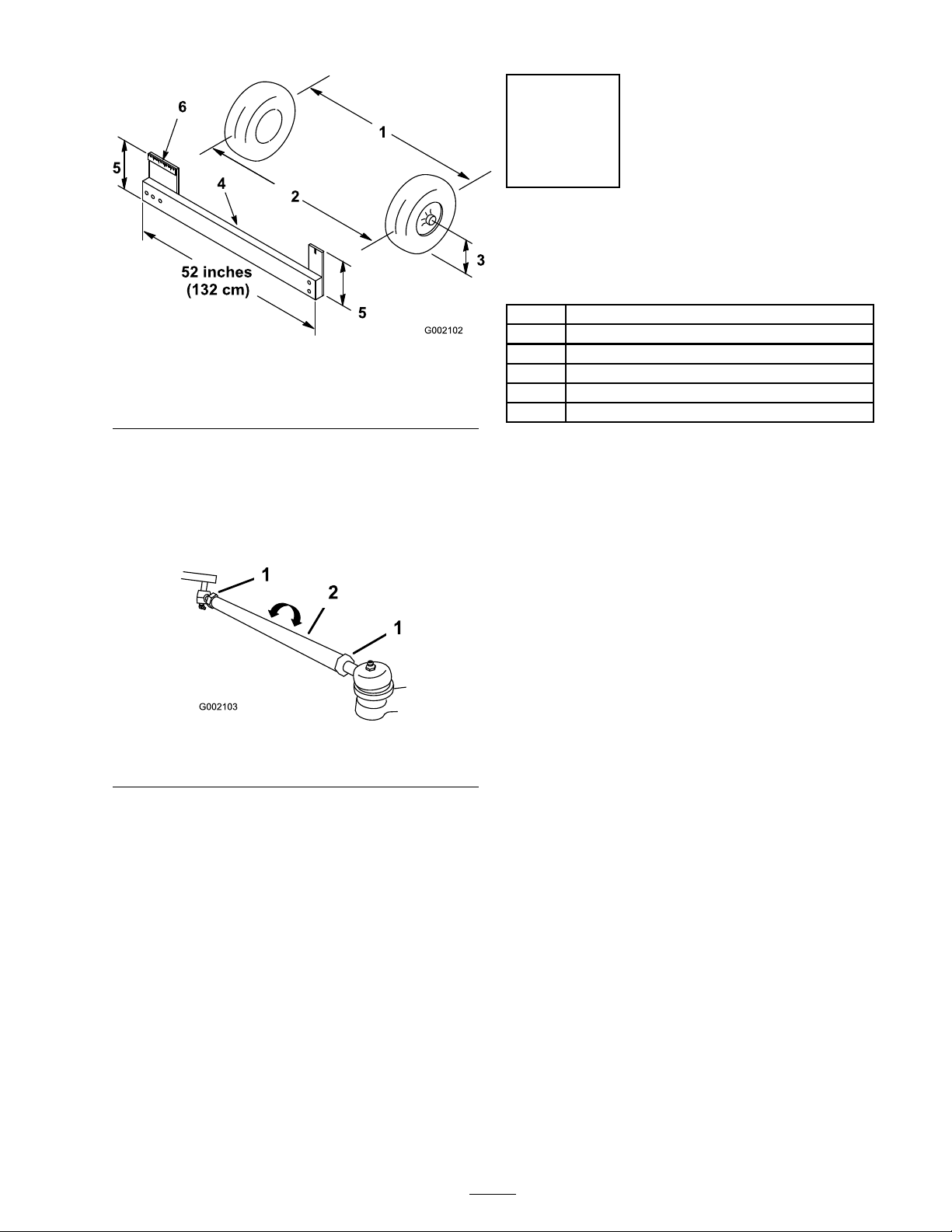
Figure 15
1. Tire center line-back
2. Tire center line-front 5. Axle center line distance
3. Axle center line
4. Fixture
6. 6 inches (15 cm) ruler
Step
12
Reading the Manual and
Viewing the Safety Video
Parts needed for this step:
1
Operator’s Manual
1
Parts Catalog
1
Safety Video
1
Registration Card
1
Predelivery Inspection Form
2 Key
2. If the measurement does not fall within the
specified rang e (refer to the dimensions and
parameters at the beginning of this procedure),
loosen the jam n uts at both ends of the tie
rods ( Figure 16 ).
Figure 16
1. Jam nut
2. Tie rod
3. R otate both tie rods to mo v e the front of the
tire inw ard or outw ard.
4. Tighten the tie rod jam n uts when the
adjustment is cor rect.
Procedure
• R ead the Operator’ s Manual .
• View the safety video .
• Fill out the registration card.
• Complete the Pr edeli ver y Inspection F or m .
5. Ensure that there is full tra v el of the steering
wheel in both directions .
19
Page 20
Product Overview
G005085
1
2
6
3
5
4
Figure 17
1. Steering wheel
2. Parking brake 4. Charging receptacle 6. Cargo box
3. Towing tongue
5. Cargo box release lever
Controls
Accelerator Pedal
T he accelerator pedal ( Figure 18 ) gi v es y ou
the ability to v ar y g round speed of the v ehicle .
Pressing the pedal when the On/Off switc h is
on star ts the motor . Pressing the pedal far ther
increases g round speed. R eleasing the pedal will
slo w the v ehicle and the motor will stop r unning .
Figure 18
1. Accelerator pedal 2. Brake pedal
Brake Pedal
T he brak e pedal is used to stop or slo w the v ehicle
( Figure 18 ).
Brak es can become w or n or can be
misadjusted r esulting in per sonal injur y .
If brak e pedal tra v els to within 1 inch
(25 mm) of the v ehicle floor board, the
brak es must be adjusted or r epair ed.
Parking Brake
T he parking brak e is betw een the seats ( Figure 19 ).
W henev er the v ehicle is shut off or when lea ving
the v ehicle , the parking brak e m ust be eng ag ed
to prev ent accidental mo v ement of the v ehicle .
T o eng ag e the parking brak e , pull bac k on the
lev er . T o diseng ag e , push the lev er forw ard. If the
v ehicle is park ed on a stee p g rade , mak e sure that
the parking brak e is applied. Place bloc ks at the
do wnhill side of the wheels .
20
Page 21
side . F or detailed infor mation on the batter y
meter , refer to Understanding and Using the
Batter y System in Operation , pag e 24 .
T he hour meter is located at the bottom of the
LCD screen. It logs operating hours whenev er
the k ey is in the On position and the v ehicle is in
motion.
Figure 19
1. Parking brake lever
On/Off Switch
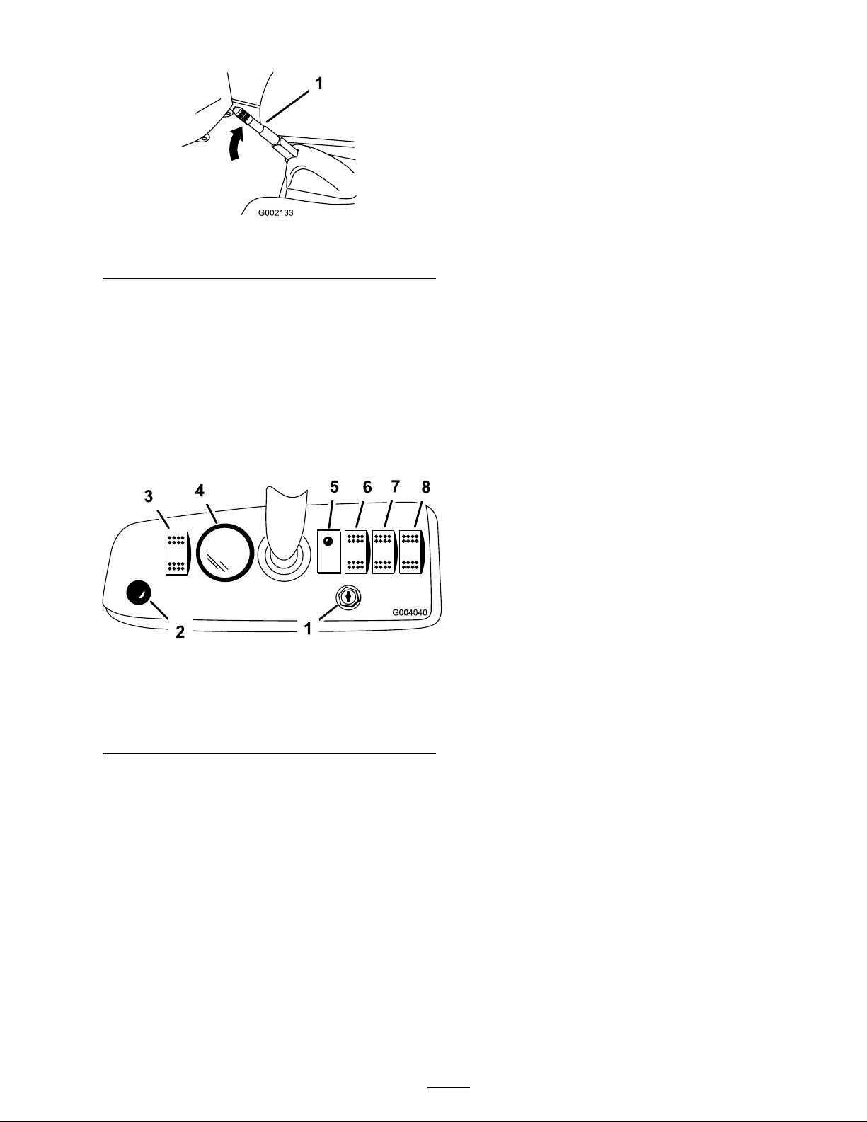
T he On/Off switc h ( Figure 20 ) used to acti v ate
the electrical systems of the v ehicle , has tw o
positions: Off and On. R otate the k ey cloc kwise to
the On position to allo w operation of the v ehicle
and accessories . After stopping the v ehicle , rotate
the k ey countercloc kwise to the Off position.
R emo v e the k ey before lea ving the v ehicle .
Vehicle Direction Switch
Use this switc h ( Figure 20 ) to tog gle betw een
forw ard and rev erse operation.
Vehicle Status Light
T he v ehicle contains a computer that monitors
the state of the v ehicle electrical systems . T his
computer comm unicates the status of the v ehicle
to y ou through the v ehicle status light. Alw a ys
c hec k this light when y ou tur n the On/Off switc h
to the On position ( Figure 24 ) W hen there are no
problems and the v ehicle is operational, the light
is on.
W hen there is a problem, the light flashes . T he
light flashes at v arious inter v als for different
problems and ev ents . If the light blinks , refer to
T roubleshooting , pag e 40 for a description of the
flash codes .
Light Switch
Figure 20
1. On/Off switch 5. Vehicle status light
2. Horn button 6. Power cargo bed switch
3. Light switch
4. Battery/hour meter 8. Vehicle direction switch
(optional)
7. Rear lift switch (optional)
Horn Button
Press the hor n button to acti v ate the v ehicle hor n
( Figure 20 ).
Gear Shift Selector
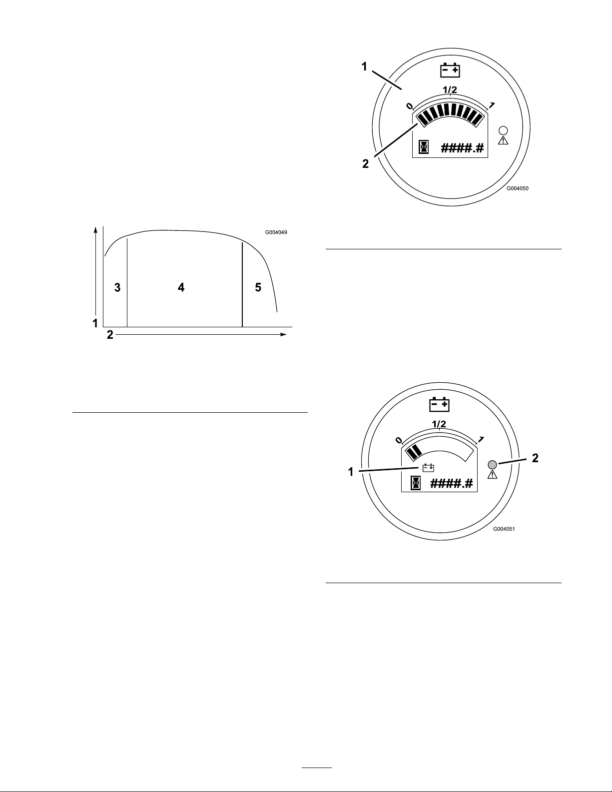
T he batter y/hour meter pro vides y ou with an
indication of ho w m uc h c harg e is contained in the
batteries ( Figure 20 and Figure 24 ) and the n umber
of operating hours on the v ehicle . T he batter y
meter is located at the top of the LCD screen.
W hen the v ehicle batteries are fully c harg ed, ten
bars extend from the 0 to the 1 position. As the
c harg e is used, bars disappear star ting on the right
Use this switc h to tur n the headlights on and off
( Figure 20 ).
Cargo Bed Lift Switch (Optional)
Use this switc h to raise and lo w er the carg o bed
( Figure 20 ).
Rear Lift Switch (Optional)
Use this switc h to raise and lo w er the rear lift
( Figure 20 ).
Supervisor Speed Limit Switch
T he super visor speed limit switc h, located under
the cup holder ( Figure 21 ) has tw o positions:
Off and On. R otate the k ey cloc kwise to the On
position to limit the maxim um v ehicle speed to a
factor y setting of 12 mph (19 kph). R otate the k ey
countercloc kwise to the Off position to restore the
maxim um speed of the v ehicle .
21
Page 22
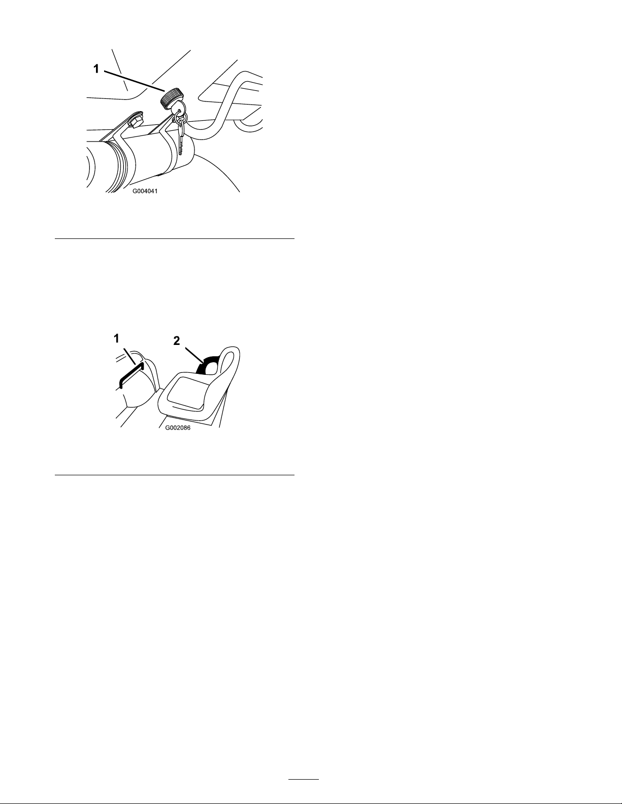
Figure 21
1. Supervisor speed limit switch
Passenger Hand Holds
T he passeng er hand holds are located on the right
side of the dash panel and at the outside of eac h
seat ( Figure 22 ).
Figure 22
1. Passenger hand hold
2. Hip restraint
22
Page 23

Specications
Note: Specifications and design are subject to c hang e without notice .
Base weight
Rated capacity (on level ground) 1200 lb (544.5 kg)* total, including 200 lb (90.7 kg) operator and 200 lb (90.7
Maximum gross vehicle weight
(GVW) (on level ground)
Maximum cargo capacity (on
level ground)
Tow capacity:
Standard Hitch
Heavy Duty Hitch
Overall width
Overall length
Ground clearance
Wheel base
Wheel tread (center line to center
line)
Cargo box length
Cargo box width
Cargo box height
1500 lb (680 kg)*
kg) passenger, load, trailer tongue weight, gross trailer weight, accessories, and
attachments
2700 lb (1225 kg) total, including all of the weights listed above
800 lb (362 kg)* total, including trailer tongue weight and gross trailer weight
Tongue weight 50 lb (23 kg) Maximum trailer weight 400 lb (182 kg)
Tongue weight 100 lb (45 kg) Maximum trailer weight 800 lb (363 kg)
60 in (152.4 cm)
119 in (302.3 cm)
9-1/4 inches (23.5 cm) at the front with no load or operator, 7 inches (18 cm) at
the rear with no load or operator
81 in (205.7 cm)
49 inches (124.5 cm) in the front, 48-1/4 inches (122.6 cm) in the rear
46 inches (116.8 cm) inside, 51 inches (129.5 cm) outside
49 inches (124.5 cm) inside, 54 inches (137.2 cm) outside
10 inches (25.4 cm) inside
* S p e c i fi c a t i o n s l i s t e d a r e w i t h T r o j a n T 1 0 5 b a t t e r i e s . I f t h e m a c h i n e i s
e q u i p p e d w i t h T r o j a n T 1 4 5 b a t t e r i e s t h e b a s e w e i g h t i s i n c r e a s e d b y 8 0
l b ( 3 6 k g ) a n d c a p a c i t i e s a r e d e c r e a s e d b y t h e s a m e a m o u n t .
Attachments/Accessories
A selection of T oro appro v ed attac hments and accessories are a v ailable for use with the mac hine to
enhance and expand its capabilities . Contact y our A uthorized Ser vice Dealer or Distributor or g o to
www .T oro .com for a list of all appro v ed attac hments and accessories .
23
Page 24

Operation
Note: Deter mine the left and right sides of the
mac hine from the nor mal operating position.
2. Sit in the Operator’ s seat, inser t the k ey into the
On/Off switc h, and rotate the k ey cloc kwise
to the On position.
3. Mo v e the v ehicle direction switc h button to
the desired position.
Think Safety First
Please carefully read all of the safety instr uctions
and decals in the safety section. Kno wing this
infor mation could help y ou or b ystanders a v oid
injur y .
Pre-Starting Checks
Chec k the follo wing items eac h time y ou begin
using the v ehicle for the da y:
• Chec k the tire pressure .
• Chec k the brak e pedal operation.
• Chec k to see that the lights are w orking .
• T ur n the steering wheel to the left and right to
c hec k steering response .
• Chec k for loose par ts and any other noticeable
malfunctions . Mak e sure the v ehicle is off and
all mo ving par ts ha v e stopped before c hec king
for loose par ts and other malfunctions .
If any of the abo v e items are not cor rect, notify
y our mec hanic or c hec k with y our super visor
before taking the v ehicle out for the da y . Y our
super visor ma y w ant y ou to c hec k other items on
a daily basis , so ask what y our responsibilities are .
4. R elease the parking brak e .
5. Slo wly ste p on the accelerator pedal to dri v e
the v ehicle .
Note: T he parking brak e will automatically
diseng ag e when y ou press the accelerator pedal.
Stopping the Vehicle
Important: W hen stopping the v ehicle on
an incline, use the brak e to stop the v ehicle
and the par king brak e to hold it in place.
Using the accelerator to stall the v ehicle can
dama ge the v ehicle.
T o stop the v ehicle , remo v e y our foot from the
accelerator pedal and slo wly press the brak e pedal.
Note: Stopping distance ma y v ar y de pending on
the v ehicle load and speed.
Parking the Vehicle
1. Eng ag e the parking brak e and rotate the
On/Off k ey to Off .
2. R emo v e the k ey from the switc h to prev ent
accidental star ting .
Checking the Tire Pressure
Chec k the tire pressure ev er y 8 hours or daily to
ensure proper lev els .
T he air pressure rang e in the front and rear tires is
8–22 psi (55–103 kP a).
T he air pressure needed is deter mined b y the
pa yload car ried. T he lo w er the air pressure , the
less the compaction, smoother the ride , and tire
marks are minimized. Lo w er pressure should not
be used for hea vy pa yloads at high speeds .
Higher pressures should be used for hea vier
pa yloads at higher speeds . Do not ex ceed the
maxim um pressure .
Operating the Vehicle
1. Disconnect the batter y c harg er .
Understanding and Using
the Battery System
Understanding Deep Cycle Batteries
T he v ehicle contains 8 dee p cycle , lead-acid
batteries whic h supply po w er to the motor and
accessories . A dee p cycle batter y is not the same
as an automobile batter y . An automobile batter y is
designed to pro vide a surg e of po w er to star t the
v ehicle and moderate po w er to r un the lights and
accessories when the motor if off or idling . T he
alter nator then contin uously rec harg es it as the
automobile r uns . As suc h, an automobile batter y
seldom drops belo w 90% of maxim um c harg e
lev el.
A dee p cycle batter y is designed to be a primar y
po w er source to pro vide a sustained output. Dee p
cycle batteries are typically disc harg ed as lo w as
24
Page 25
20% to 30% of the maxim um c harg e lev el. A
disc harg e this lo w is considered a dee p disc harg e .
Lead acid batteries produce electricity through
a c hemical reaction betw een coated lead plates
and sulfuric acid. Charging a batter y rev erses the
c hemical reaction, allo wing the batter y to once
ag ain produce electricity .
A batter y is a perishable item that has a limited life
time ( Figure 23 ). W hen a batter y is new , it requires
a break-in period to establish efficient electrical
production. T his break in period usually requires
20 to 50 disc harg e/c harg e cycles .
Figure 23
1. Battery capacity
2. Discharge/charge cycles 5. End of battery life
3. Break-in period (20 to 50
cycles)
4. Prime battery life
Figure 24
1. Battery/hour meter 2. Charge indicator bars
As y ou use the v ehicle , the bars will disappear as
the electrical capacity of the batteries is used.
W hen only 2 bars are left, the red w ar ning light
on the meter will illuminate and the batter y icon
will begin flashing on the screen ( Figure 25 ). T his
indicates that the batter y capacity is nearly drained
and y ou should c harg e the batteries as soon as
possible to prev ent batter y damag e .
After the break-in period, the batter y will maintain
a high capacity for many cycles . T he n umber of
cycles a batter y will perfor m is de pendant on the
follo wing:
• Batter y maintenance—improper maintenance
will sev erely reduce the life of the batteries .
• De pth of disc harg e betw een c harg e
cycles— the deeper the batteries ar e
discharged on a r egular basis betw een
charges, the less life they will ha v e.
• R ec harg e frequency—c harg e the batteries
whenev er they are not in use . Full y
discharging the batteries will dama ge them
and r educe their life.
At the end of the batter y life , the coating on
the lead plates begins to deteriorate , causing the
batteries to rapidly lose electric capacity .
Using the Battery System
W hen y our batteries are fully c harg ed, the batter y
meter will ha v e ten bars sho wing from left to right
( Figure 24 ).
Figure 25
1. Battery icon
2. Warning light—on
W hen only one bar is left, the w ar ning light will
begin flashing and the v ehicle will g o into an
energ y sa ving mode ( Figure 26 ). In this mode ,
the v ehicle will only dri v e at 3 mph. R ec harg e the
batteries immediately to prev ent serious damag e
to them.
If the batteries become fully disc harg ed, the v ehicle
will shut do wn. Do not allo w the batteries to
become full y discharged.
25
Page 26

Important: T o obtain maximum batter y
life, al w ays charge the batteries when ther e ar e
2 or mor e bar s visible on the scr een. Depleting
the batteries lo w er than 2 bar s, especiall y
on a r egular basis, will r educe the life of the
batteries.
Figure 26
1. Battery icon
2. Warning light-ashing
Figure 27
1. Lever
2. Pull the prop rod into the detent slot, securing
the bo x ( Figure 28 ).
Operating the Cargo Box
Raising the Box
Dri ving the v ehicle with the cargo bo x raised
may cause the v ehicle to tip or r oll easier .
T he bo x str uctur e may become dama ged if
y ou operate the v ehicle with the bo x raised.
• Onl y operate the v ehicle when the cargo
bo x is do wn.
• After dumping a load, lo w er the cargo
bo x.
1. Lift the lev er on either side of the bo x and lift
the bo x up ( Figure 27 ).
Figure 28
1. Prop rod 2. Detent slot
Lowering the Box
T he w eight of the bo x may be hea vy . Hands
or other body par ts could be cr ushed.
K eep hands and other body par ts clear when
lo w ering the bo x.
Pull the prop rod out of the detent slot and lo w er
the bo x until it latc hes into place .
Adjusting the Box Latches
If the bo x latc h does not latc h tightly , vibrating up
and do wn as y ou dri v e the v ehicle , y ou can adjust
the latc h posts to mak e the latc hes fit sn ugly .
1. Loosen the n ut on the end of the latc h post
( Figure 29 ).
26
Page 27

Figure 29
1. Latch 3. Latch post
2. Nut
2. T ur n the latc h post cloc kwise until it is sn ug
ag ainst the latc h and then tighten the n ut
( Figure 29 ).
3. R e peat this procedure for the latc h on the
other side of the v ehicle .
Breaking in a New Vehicle
T o pro vide proper perfor mance and long
v ehicle life , follo w these guidelines for the first
100 operating hours:
• A v oid hard braking situations for the first
sev eral hours of new v ehicle break-in
operation. New brak e linings ma y not be at
optim um perfor mance until sev eral hours of
use has caused the brak es to become bur nished
(brok en-in).
• R efer to the Maintenance section for any
special lo w hour c hec ks .
• Chec k the front suspension positioning
and adjust it if necessar y; refer to
Adjusting the F ront Suspension in
Dri v e System Maintenance , pag e 35 .
Loading the Cargo Box
Operating the Tailgate Latches
1. T o open the tailg ate latc hes , lift the latc h
handles up ( Figure 30 ). T he latc hes will spring
out to w ard the center of the tailg ate . Slo wly
lo w er the tailg ate .
Note: Y ou ma y need to push the end of the
tailg ate in (especially if there is a load ag ainst
the tailg ate) before the latc hes will spring
to w ard the center of the tailg ate and release .
Figure 30
1. Tailgate latch
2. T o close the tailg ate latc hes , lift the handles
upw ard and slide them to w ard the outside of
the v ehicle .
T he capacity of the carg o bo x is 13 ft
3
(0.37 m
T he amount (v olume) of material that can be
placed in the bo x without ex ceeding the v ehicle
load ratings can v ar y g reatly de pending on the
density of the material. F or example , a lev el bo x
of w et sand w eighs 1500 lb (680 kg), whic h g reatly
ex ceeds the load rating .
See the table belo w for load v olume limits with
v arious materials:
3
)
Max. cargo box
capacity (on level
ground)
1/2 full
1/3 full
1/2 full
1/3 full
Full
Full
1/2 full
Gravel, dry95
Gravel, wet
Sand, dry
Sand, wet
Wood
Bark
Earth, packed
Material Material
(lb/ft
95
120
90
120
45
<45
100
Transporting the Vehicle
3
).
3. Push the latc h handles do wnw ard to secure the
latc h and tailg ate .
F or mo ving the v ehicle long distances , a trailer
should be used. Mak e sure that the v ehicle is
secured to the trailer . R efer to Figure 31 and
Figure 32 for the location of the tie-do wn points .
27
Page 28

Loose seats may f all of f of the v ehicle
and trailer when transpor ting and land on
another v ehicle or become an obstr uction
on the r oad.
R emo v e the seats or mak e sur e that the seats
ar e secur el y f astened in the detents.
Figure 31
1. Tie down points
Towing the Vehicle
In case of an emerg ency , the v ehicle can be
to w ed for a shor t distance . Ho w ev er , w e do not
recommend this as a standard procedure .
Figure 32
1. Towing tongue and tie down point
Towing a Trailer
T he v ehicle is capable of pulling trailers . T w o
types of to w hitc hes are a v ailable for the v ehicle ,
de pending on y our application. Contact y our
A uthorized T oro Distributor for details .
W hen hauling carg o or to wing a trailer , do not
o v erload y our v ehicle or trailer . Ov erloading can
cause poor perfor mance or damag e to the brak es ,
axle , motor , transaxle , steering, suspension, body
str ucture , or tires . Alw a ys load a trailer with 60%
of the carg o w eight in the front of the trailer . T his
places appro ximately 10% of the Gross T railer
W eight (GTW) on the to w hitc h of the v ehicle .
T o wing at ex cessi v e speeds could cause a
loss of steering contr ol, r esulting in per sonal
injur y .
Nev er to w the v ehicle f aster than 5 mph
(8 km/h).
T o wing the v ehicle is a tw o person job . If
the mac hine m ust be mo v ed a considerable
distance , transpor t it on a tr uc k or trailer; refer to
T ranspor ting the V ehicle .
1. T ur n off the On/Off switc h and remo v e the
k ey .
2. Affix a to w line to the tongue on the front of
the frame ( Figure 32 ).
3. Put the v ehicle in neutral and release the
parking brak e .
T he maxim um carg o load shall not ex ceed 800 lb
(362 kg), including the GTW and tongue w eight.
F or example , if the GTW = 200 lb and tongue
w eight = 50 lb , then the maxim um carg o load =
550 lb .
T o pro vide adequate braking and traction, alw a ys
load the carg o bo x when trailering . Do not ex ceed
the GTW limits .
A v oid parking a v ehicle with a trailer on a hill. If
y ou m ust park on a hill, eng ag e the parking brak e
and bloc k the trailer tires .
28
Page 29

Maintenance
Note: Deter mine the left and right sides of the mac hine from the nor mal operating position.
Recommended Maintenance Schedule(s)
Maintenance Service
Interval
After the rst 25
operating hours
Before each use or daily
Every 25 hours
Every 100 hours
Every 200 hours
Every 800 hours
Maintenance Procedure
• Check the front wheel toe-in and front suspension.
• Check the tire pressure.
• Charge the batteries.
• Check the brake uid level.
• Clean the batteries.
• Check the battery electrolyte level.
• Lubricate all grease ttings.
• Inspect the condition and wear of the tires.
•
Torque the wheel lug nuts to 45-65 ft-lb (61-88 N ⋅ m).
• Check the front wheel toe-in and front suspension.
• Check the transaxle uid.
• Inspect the brakes.
• Adjust the parking brake.
• Change the transaxle uid.
29
Page 30

Daily Maintenance Checklist
Duplicate this page for routine use.
Maintenance Check
Item
Check brake and parking
brake operation.
Check gear shift/neutral
operation.
Check unusual operating
noises.
Check tire pressure.
Check uid leaks.
Check instrument
operation.
Check accelerator
operation.
Check ride height and
toe-in.
Lubricate all grease
ttings.
Touch up damaged paint.
For the week of:
Mon. Tues.
Wed. Thurs.
Fri.
Sat. Sun.
If y ou lea v e the k ey in the On/Of f s witch, someone could accidentl y star t the v ehicle and
seriousl y injur e y ou or other bystander s.
R emo v e the k ey fr om the On/Of f s witch and disconnect a batter y ca ble bef or e y ou do an y
maintenance.
T he bed must be raised to perf or m some r outine maintenance.
A raised bed can f all and injur e per sons that ar e under neath it.
• Al w ays use the pr op r od to hold the bed up bef or e w or king under it.
• R emo v e an y load material fr om the bed bef or e w or king under it.
Premaintenance
Procedures
• Deser t operation
• Cold climate operation (belo w 32 deg rees F)
• T railer to wing
Heavy Duty Operation
• F requent operation on dusty roads
• Constr uction w ork
Important: If the v ehicle is subjected to an y
of the conditions listed belo w , maintenance
should be perf or med twice as fr equentl y:
• After extended operation in m ud, sand, w ater ,
or similar dir ty conditions , ha v e y our brak es
inspected and cleaned as soon as possible . T his
30
Page 31

will prev ent any abrasi v e material from causing
ex cessi v e w ear .
• Under frequent hea vy duty operating
conditions , lubricate all g rease fittings .
Jacking the Vehicle
W henev er the motor is r un for routine
maintenance and/or diagnostics , the rear wheels
of the v ehicle should be 1 inc h (25 mm) off of the
g round with the rear axle suppor ted on jac k stands .
T he v ehicle may be unsta ble when using
a jack. It could slip of f the jack, injuring
an y one beneath it.
• Do not star t the v ehicle while the v ehicle
is on a jack.
• Al w ays r emo v e the k ey fr om the ignition
bef or e getting of f of the v ehicle.
• Block the tir es when the v ehicle is on a
jack.
Lubrication
Lubricate all of the bearings and bushings ev er y
100 hours or once a year , whic hev er occurs first.
Grease them more frequently when using the
v ehicle for hea vy-duty operations .
Grease T ype: Number 2 General Pur pose Lithium
Base Grease
Where to Add Grease
T he g rease fittings are located at the four tie rod
ends ( Figure 35 ) and the tw o king pins ( Figure 36 ).
1. Wipe the g rease fitting clean so foreign matter
cannot be forced into the bearing or bushing .
2. Pump g rease into the bearing or bushing .
3. Wipe off ex cess g rease .
T he jac king point at the front of the v ehicle is on
the front of the frame behind the to wing tongue
( Figure 33 ) T he jac king point at the rear of the
v ehicle is under the axle tubes ( Figure 34 ).
Figure 33
1. Front jacking point
Figure 35
Figure 36
1. Rear jacking points
Figure 34
31
Page 32
Electrical System
Maintenance
batter y life , c harg e the batteries whenev er y ou
are not using the v ehicle . De pending on ho w
disc harg ed the batteries are , it ma y tak e up to 16
hours to c harg e the batteries to full capacity .
Maintaining the Batteries
Batter y ter minals or metal tools could shor t
a gainst metal v ehicle components causing
spar ks. Spar ks can cause the batter y gasses
to explode, r esulting in per sonal injur y .
• W hen r emo ving or installing the batter y ,
do not allo w the batter y ter minals to
touch an y metal par ts of the v ehicle.
• Do not allo w metal tools to shor t betw een
the batter y ter minals and metal par ts of
the v ehicle.
• Al w ays k eep the batter y r etainer s in place
to pr otect and secur e the batteries.
Warning
CALIFORNIA
Pr oposition 65 W ar ning
Important: Lead-acid batteries do not
dev elop a charge memor y and do not need
to be full y discharged bef or e charging them.
Full y discharging the batteries may dama ge
them. Charge the batteries whenev er the
v ehicle gets lo w on po w er and an y time it is
not in use; r efer to Using the Batter y System
section in Operation , pa ge 24 .
Charging the batter y pr oduces gasses that
can explode.
Nev er smok e near the batteries and k eep
spar ks and flames a w ay fr om them.
1. P osition the v ehicle in a w ell v entilated area
near a 115 v ac , 15 amp po w er outlet.
2. Connect the c harg er cord to the c harging
rece ptacle on the v ehicle (located on the panel
betw een the seats).
Batter y posts, ter minals, and r elated
accessories contain lead and lead
compounds, chemicals kno wn to the State of
Calif or nia to cause cancer and r epr oducti v e
har m. W ash hands after handling .
Cleaning the Batteries
Clean the batteries ev er y da y before use .
1. Ensure that all of the batter y caps are tight.
2. Use a paper to w el to clean the batteries .
3. If the batter y ter minals are cor roded, clean
them with a solution of four par ts w ater and
one par t baking soda. Also , clean the posts and
cable clamps with a post and clamp cleaner .
T he posts and clamps should ha v e a bright
metallic shine .
4. Apply a light coating of T oro batter y ter minal
protector .
Charging the Batteries
3. Plug the c harg er po w er cord into a 115 v ac ,
15 amp po w er outlet.
W hile the batteries are c harging, the g reen light
on the c harg er will blink on and off . W hen the
batteries are fully c harg ed, the g reen light stops
blinking and sta ys on.
4. Disconnect the cord from the po w er outlet.
5. Disconnect the c harg er from the v ehicle .
Important: Do not car r y the charger on the
v ehicle. Ex cessi v e or pr olonged jar ring may
dama ge it.
Adding Water to the Batteries
Chec k the electrolyte lev el and add w ater if needed
ev er y 25 operating hours or , if the v ehicle is in
storag e , ev er y 30 da ys . Use onl y clean, distilled
w ater to fill the batteries.
A c harg er is supplied with the v ehicle . Alw a ys
k ee p the c harg er in a dr y location. F or maxim um
32
Page 33
Batter y electr ol yte contains sulfuric acid
which is a deadl y poison and causes sev er e
bur ns.
• Do not drink electr ol yte and a v oid
contact with skin, ey es or clothing . W ear
safety g lasses to shield y our ey es and
r ub ber g lo v es to pr otect y our hands.
Important: Do not o v erfill the batter y .
Electr ol yte will o v erflo w onto other par ts
of the v ehicle and sev er e cor r osion and
deterioration may r esult. Also, o v erfilling
the batter y will r educe the life of the
batter y .
8. R e place the filler caps on all batteries .
Replacing Used Batteries
• Fill the batteries wher e clean w ater is
al w ays a v aila ble f or flushing the skin.
• Nev er add acid to a batter y .
1. Raise the carg o bed, tur n the k ey off , and
remo v e it.
2. R emo v e the filler caps from eac h batter y .
3. If the electrolyte is not o v er the top of the
plates in eac h batter y cell, add just enough
distilled w ater to co v er the plates .
4. R e place the filler caps on all batteries .
5. Charg e the batteries for 16 hours; refer to
Charging the Batteries .
6. R emo v e the filler caps from eac h batter y .
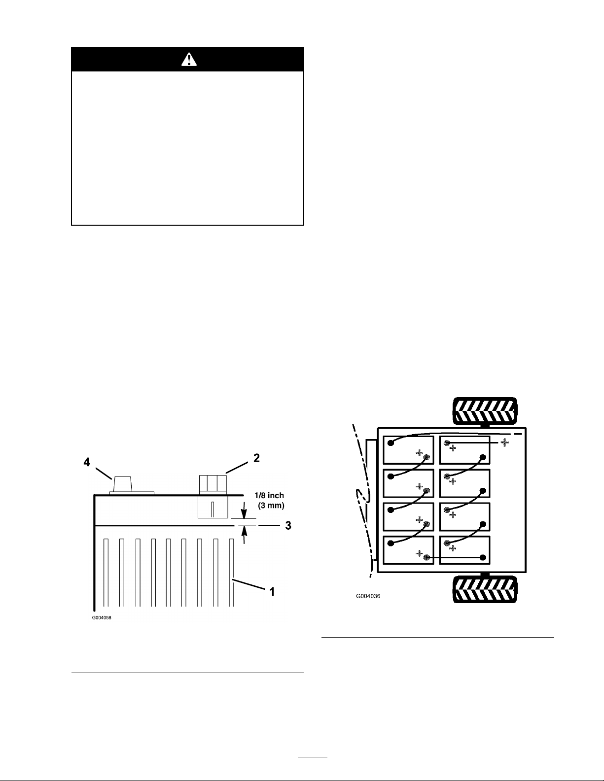
7. Add just enough distilled w ater to bring the
electrolyte lev el to 1/8 inc h (3 mm) belo w the
bottom of eac h fill w ell ( Figure 37 ).
W hen the v ehicle begins to sho w a loss of rang e
or when the length of the disc harg e/c harg e cycle
is significantly reduced, the batteries are probably
g etting old and losing their ability to hold a c harg e .
T ak e the v ehicle to an A uthorized Ser vice Dealer
and ha v e them test the batteries to deter mine
whether the batteries need to be re placed. T he
Dealer can then re place the batteries for y ou. If
y ou wish to re place the batteries y ourself , use the
follo wing procedure:
1. Raise the carg o bed, tur n the k ey off , and
remo v e it.
2. Disconnect the long, blac k, main neg ati v e lead
r unning from the bank of batteries to the
v ehicle from the batter y post ( Figure 38 ).
Figure 37
1. Battery plates 3. Electrolyte level
2. Filler cap 4. Battery terminal
Figure 38
3. R emo v e the long, red, main positi v e lead
r unning from the bank of batteries to the
v ehicle from the batter y post ( Figure 38 ).
4. Disconnect all of the batter y leads from the
batteries .
33
Page 34
5. R emo v e the batter y retainers located betw een
the batteries .
6. R emo v e all of the batteries and recycle them
according to y our local codes .
7. Install new batteries in the places v acated b y
the old batteries
Note: P a y attention to the batter y polarity
when installing the new batteries ( Figure 38 ).
8. Install the batter y retainers and tor que the n uts
to 150 to 200 in-lb (17 to 22 N ⋅ m).
9. Connect the batteries tog ether with the
batter y cables remo v ed previously , as sho wn
in Figure 38 .
10. Connect the long, red, main positi v e lead
betw een the bank of batteries and the v ehicle
( Figure 38 ).
11. Connect the long, blac k, main neg ati v e lead
betw een the bank of batteries and the v ehicle
( Figure 38 ).
12. T or que the n uts securing all batter y cables to
120 to 180 inc h-lb (13.5 to 21 N ⋅ m).
13. Coat the batter y ter minals with T oro batter y
ter minal protector .
14. Ensure that the r ubber boots on eac h batter y
cable are securely seated o v er the batter y
ter minals .
Storing the Batteries
Charg e the batteries fully before placing the
v ehicle into storag e . Plug the c harg er into a w all
outlet while the v ehicle and batteries are in storag e .
Lea v e the c harg er plug g ed into a w all outlet and
c harging rece ptacle during storag e to ensure that
the batteries sta y c harg ed and do not freeze;
otherwise , c harg e the batteries at least once ev er y
3 months .
Figure 39
1. Vehicle fuse
2. Accessories Fuse
Replacing the Headlights
Specification: T oro #104-7312, 28 v olt
Note: T he headlights are wired in series;
therefore , when one headlight bur ns out, neither
will illuminate . If possible , c hang e both headlights
at the same time .
1. Set the parking brak e , tur n the v ehicle off , and
remo v e the k ey .
2. R eac h beneath the dash and push the headlight
out of the hood.
3. R emo v e the screws attac hing the wire har ness
to the headlight.
4. R emo v e the r ubber seal from around the
headlight ( Figure 40 ). Discard the headlight.
Replacing the Fuses
T here are 3 fuses in the electrical system. T hey are
located beneath the bed in a bo x on the right hand
side of the frame ( Figure 39 ).
Ignition System
Lights
Power Point
10 amp. (15 amp. max.)
10 amp.
10 amp.
Figure 40
1. Rubber seal 3. Outside notch-align with
2. Inside notch-align with the
notch on the headlight
34
notch in hood
4. Headlight
Page 35
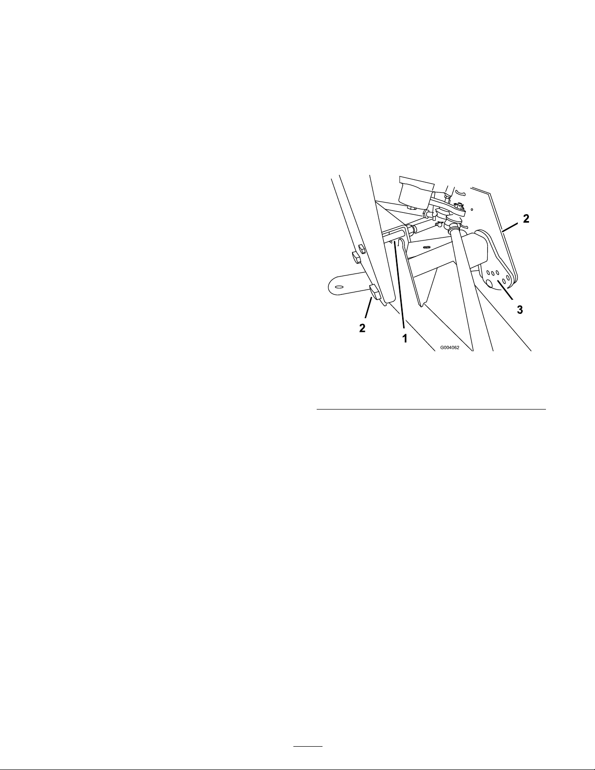
5. Align the notc h on the inside of the seal with
the notc h on the new headlight ( Figure 40 ).
Slide the seal onto the headlight until the seal
is fir mly in place .
6. Attac h the headlight to the wire har ness using
the previously remo v ed screws .
7. Align the notc h on the outside of the seal with
the notc h in the hood. Push the headlight and
seal into the hood until it is fir mly in place .
Note: Applying soapy w ater to the outside
of the seal ma y aid in sliding the seal into the
hood.
Drive System
Maintenance
Inspecting the Tires
Chec k the tire condition at least ev er y 100 hours
of operation. Operating accidents , suc h as hitting
curbs , can damag e a tire or rim and also disr upt
wheel alignment, so inspect tire condition after an
accident.
Chec k the wheels to ensure that they are mounted
securely . T or que the center bolts on the front
wheels to 135-165 ft-lb (183-224 N ⋅ m) and the
front and rear lug n uts to 45-65 ft-lb (61-88 NVm).
Adjusting the Front
Suspension
T he ride height of eac h side of the v ehicle can
be adjusted se parately . T he ride height should be
8-3/4 to 9-1/2 inc hes (22.2 to 24 cm) with the
follo wing parameters:
• T he tire pressure should be at 12 psi (83 kP a).
• T he v ehicle should be dri v en bac k and for th a
few times to relax the A-ar ms .
• Measure the ride height with the wheels facing
straight ahead and a 175-225 lb (79-102 kg)
operator in the dri v er’ s seat.
Note: T he dri v er should dri v e up to the
measurement area and sta y seated in the v ehicle
while the measurement is being tak en.
1. J ac k the front end of the v ehicle off of
the g round; refer to J ac king the V ehicle in
Premaintenance Procedures , pag e 30 .
2. R emo v e the tra v el limiting bolt ( Figure 41 ).
3. Loosen the centering bolts in the front A-ar m
( Figure 41 ).
4. R emo v e the ride height adjustment bolt
( Figure 41 ).
Figure 41
1. Travel limiting bolt 3. Ride height adjustment
bolt
2. Centering bolt
5. R otate the front A-ar m to the desired position
(refer to the note belo w) and re place the ride
height adjustment bolt ( Figure 41 ).
Note: T he A-ar ms are made with r ubber
and ha v e different spring rates . Because of
the different spring rates , the A-ar ms come
adjusted from the factor y based on that spring
rate . Generally the adjustment bolts will be
installed in hole n umber 2, 3, or 4 ( Figure 42 )
and it ma y be different from the left side (dri v er
side) to the right side (passeng er side). If the
A-ar ms look lik e they are sag ging, then they
should be adjusted to the next higher n umber
( Figure 42 ). Eac h hole equals about 3/4 inc h
(19 mm) of adjustment at the wheel. Y ou will
also need to do this if y ou are adding hea vy
attac hments or car r ying hea vy loads often.
• Measure the ride height on a flat surface , from
the bottom of the front tongue to the g round.
35
Page 36
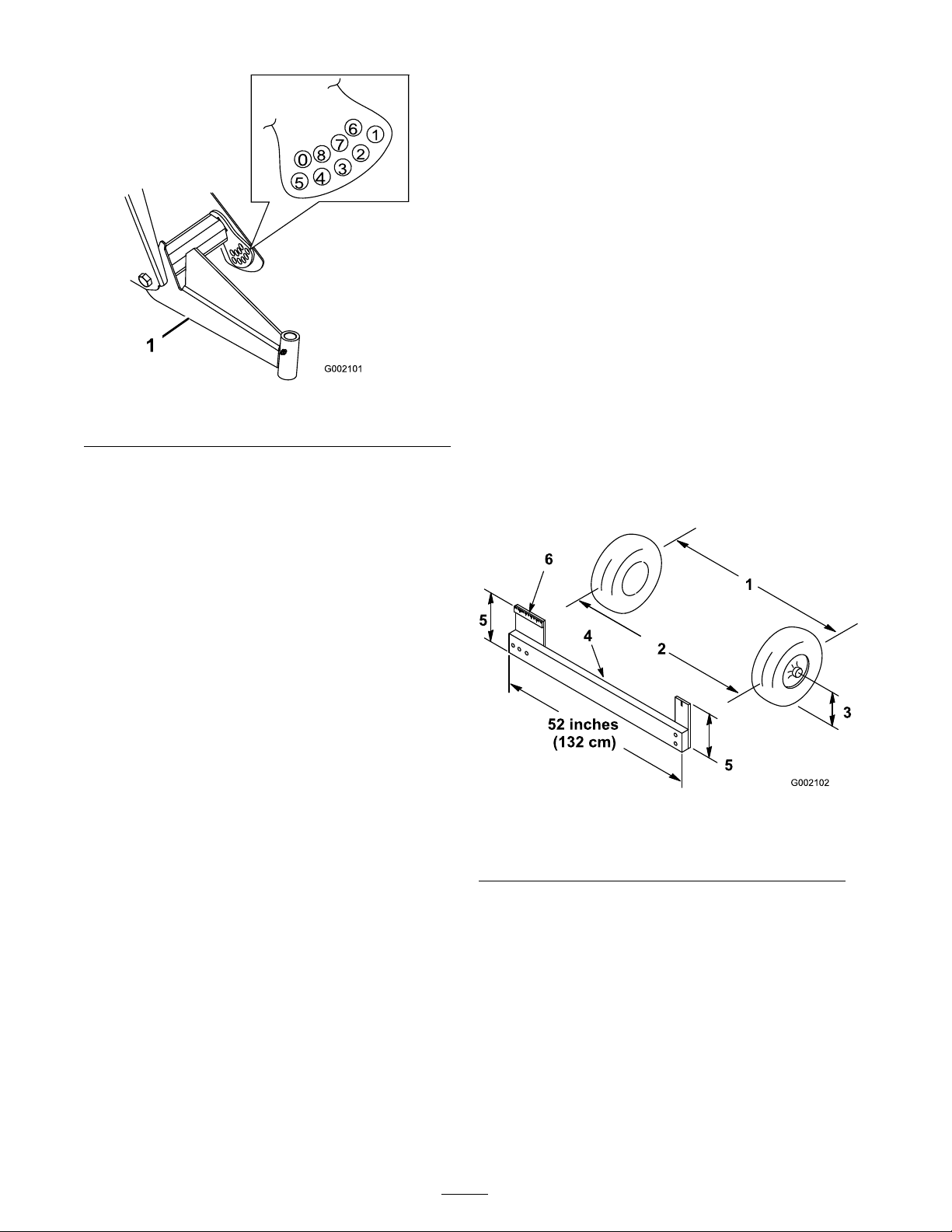
Figure 42
1. Left-hand A-arm
6. T or que the ride height adjustment bolt to
135-165 ft-lb (183-224 N ⋅ m).
7. R e place the tra v el limiting bolt ( Figure 41 ).
Note: T he dri v er should dri v e up to the
measurement area and sta y seated in the v ehicle
while the measurement is being tak en.
If the v ehicle will be r un with medium to hea vy
loads most of the time , set the toe-in on the
high side of the recommended amount. If it
is g oing to be r un with a light load most of
the time , set the toe-in on the lo w side of the
recommended amount.
1. Ensure that the front suspension is adjusted
properly; refer to Adjusting the F ront
Suspension. Adjust if necessar y .
2. Measure the distance betw een both of the
front tires at the axle height at both the front
and rear of the front tires ( Figure 43 ). A fixture
or alignment g aug e is needed for the rear
measurement of the front tires at axle height.
Use the same fixture or alignment g aug e to
accurately measure the front of the front tires
at axle height ( Figure 43 ).
Note: T he v ehicle ma y need to be lo w ered to
the g round on that side to install the bolt.
8. Tighten and tor que the centering bolts to
240-290 ft-lb (325-393 N ⋅ m).
9. Chec k the ride height at the front tongue per
the dimensions and parameters gi v en at the
beginning of this procedure .
Adjusting Front Wheel
Toe-In
Chec k the front wheel toe-in after ev er y
100 operating hours , or ann ually , whic hev er occurs
first.
T he toe-in should be 1/8-5/8 inc h (3-16 mm) with
the follo wing parameters:
• T he tire pressure should be at 12 psi (83 kP a).
• T he ride height should be cor rect before
setting the toe-in; refer to Adjusting the F ront
Suspension.
Figure 43
1. Tire center line-back
2. Tire center line-front 5. Axle center line distance
3. Axle center line
4. Fixture
6. 6 inches (15 cm) ruler
3. If the measurement does not fall within the
specified rang e (refer to the dimensions and
parameters at the beginning of this procedure),
loosen the jam n uts at both ends of the tie
rods ( Figure 44 ).
• T he v ehicle should be dri v en bac k and for th a
few times to relax the A-ar ms .
• Measure the toe-in with the wheels facing
straight ahead and a 175-225 lb (79-102 kg)
operator in the dri v er’ s seat.
36
Page 37
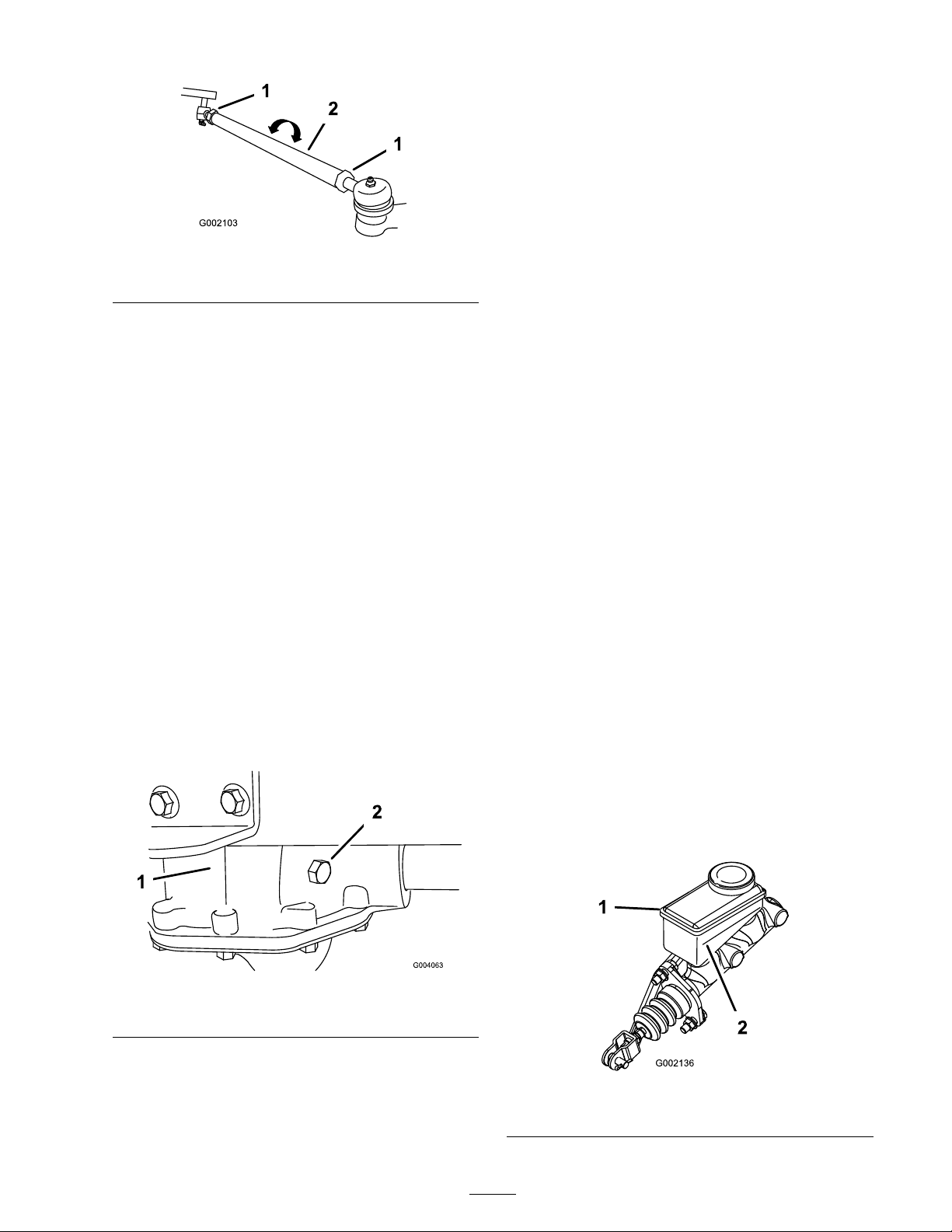
Figure 44
1. Jam nut
4. R otate both tie rods to mo v e the front of the
tire inw ard or outw ard.
2. Tie rod
Brake Maintenance
Inspecting the Brakes
Brak es are a critical safety component of the
v ehicle . As with all safety components , they should
be closely inspected at regular inter v als to ensure
optim um perfor mance and safety . T he follo wing
inspections should be done ev er y 100 hours:
• Inspect the brak e shoes for w ear or damag e .
If the lining (brak e pad) thic kness is less than
1/16 inc h (1.6 mm), the brak e shoes should
be re placed.
5. Tighten the tie rod jam n uts when the
adjustment is cor rect.
6. Ensure that there is full tra v el of the steering
wheel in both directions .
Checking the Transaxle Oil
Level
Chec k the oil lev el in the transaxle at the rear of
the v ehicle ev er y 100 operating hours . Chang e the
oil in the transaxle ev er y 800 operating hours .
1. P ark the v ehicle on a lev el surface , set the
parking brak e , and tur n off and remo v e the k ey .
2. R emo v e the c hec k bolt on the transaxle
( Figure 45 ).
T he oil lev el should be ev en with the bottom
of the c hec k hole .
• Inspect the bac king plate and other
components for signs of ex cessi v e w ear or
defor mation. If any defor mation is found, the
appropriate components m ust be re placed.
• Chec k the brak e fluid lev el; refer to Chec king
the Brak e Fluid Lev el.
Checking the Brake Fluid
Level
T he brak e fluid reser v oir is filled and shipped from
the factor y with DOT 3 brak e fluid. Chec k the
lev el before the motor is first star ted and ev er y 8
hours or daily , thereafter .
1. P ark the mac hine on a lev el surface , set the
parking brak e , tur n the ignition off , and
remo v e the k ey .
2. Look at the side of the reser v oir . T he lev el
should be abo v e the Minim um line ( Figure 46 ).
If the fluid lev el is lo w , clean the area around
the cap , remo v e the cap , and fill the reser v oir
to abo v e the Minim um line . Do not o v erfill.
Figure 45
1. Transaxle 2. Check bolt
3. If the oil lev el is lo w , add 10w30 motor oil to
the c hec k hole until it r uns out the hole .
4. R e place the c hec k bolt and tor que it to 15 to
20 ft-lb (20 to 27 N ⋅ m).
Figure 46
1. Brake uid reservoir 2. Minimum line
37
Page 38
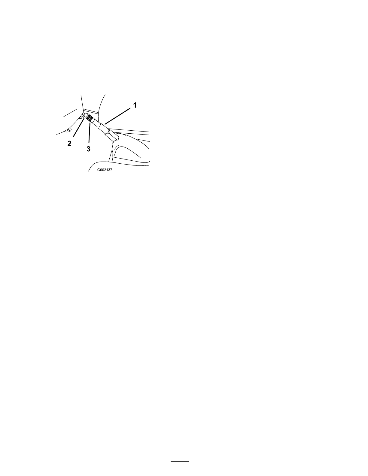
Adjusting the Parking Brake
Chec k the parking brak e adjustment ev er y 200
hours .
1. Pr y the r ubber co v er off of the parking brak e .
2. Loosen the set screw securing the knob to the
parking brak e lev er ( Figure 47 ).
Figure 47
1. Parking brake lever
2. Knob
3. Set screw
3. R otate the knob until a force of 30-35 lb
(133-156 N) is required to actuate the lev er .
4. Tighten the set screw and install the r ubber
co v er .
Cleaning
Washing the Vehicle
T he v ehicle should be w ashed as needed. Use
w ater alone or with a mild deterg ent. A rag ma y
be used, ho w ev er the hood will loose some of its
luster .
Important: Do not use high pr essur e w ater
when w ashing the v ehicle. It may dama ge the
electrical system, loosen impor tant decals, or
w ash a w ay necessar y g r ease at friction points.
A v oid ex cessi v e use of w ater , especiall y near
the contr ol panel, motor , and batteries.
38
Page 39

Storage
1. P osition the mac hine on a lev el surface , set
the parking brak e , tur n the mac hine Off , and
remo v e the k ey .
2. Clean dir t and g rime from the entire mac hine ,
including the outside of the motor housing .
Important: Y ou can w ash the machine
with mild detergent and w ater . Do not use
high pr essur e w ater to w ash the machine.
Pr essur e w ashing may dama ge the
electrical system or w ash a w ay necessar y
g r ease at friction points. A v oid ex cessi v e
use of w ater , especiall y near the contr ol
panel, lights, motor , and the batter y .
3. Inspect the brak es; refer to Inspecting the
Brak es in Brak e Maintenance , pag e 37 .
4. Grease the mac hine; refer to Lubrication ,
pag e 31 .
5. Chec k the tire pressure; refer to Chec king the
Tire Pressure .
6. Charg e the batteries fully before placing the
v ehicle into storag e , refer to Maintaining the
Batteries in Electrical System Maintenance ,
pag e 32 . Plug the c harg er into a w all outlet
while the v ehicle and batteries are in storag e .
Lea v e the c harg er plug g ed into a w all outlet
and c harging rece ptacle during storag e to
ensure that the batteries sta y c harg ed and do
not freeze; otherwise , c harg e the batteries at
least once ev er y 3 months .
7. Chec k and tighten all bolts , n uts , and screws .
R e pair or re place any par t that is damag ed.
8. P aint all scratc hed or bare metal surfaces .
P aint is a v ailable from y our A uthorized Ser vice
Dealer .
9. Store the mac hine in a clean, dr y g arag e or
storag e area.
10. R emo v e the k ey and put it in a safe place out
of the reac h of c hildren.
11. Co v er the mac hine to protect it and k ee p it
clean.
39
Page 40

Troubleshooting
Vehicle Status Light Flash Pattern
Problem
Always on
1 ash 1. The computer
2 ashes 1. The accelerator pedal
3 ashes
1. The system is functioning
1. The power block has a
Possible Cause Corrective Action
properly.
programming
personality is out of
range.
was pressed when the
On/Off key was turned.
short circuit (MOSFET
S/C).
1. None
1. Turn the On/Off key to
the Off position, wait
a few seconds, and
turn the On/Off key to
the On position. If the
condition continues,
refer to your Authorized
Service Dealer.
1. Turn the On/Off key to
the Off position, release
the accelerator pedal,
and turn the On/Off key
to the On position.
1. Turn the On/Off key
to the Off position,
wait a few seconds,
and turn the On/Off
key to the On position.
Check all batteries and
high current controller
connections If the
condition continues,
refer to your Authorized
Service Dealer.
2. A poor batter or power
cable connection.
2. Turn the On/Off key
to the Off position,
wait a few seconds,
and turn the On/Off
key to the On position.
Check all batteries and
high current controller
connections If the
condition continues,
refer to your Authorized
Service Dealer.
40
Page 41

Problem
Possible Cause Corrective Action
4 ashes 1. The line contactor is
not responding to
commands.
5 ashes 1. The charger interlock
switch is active.
6 ashes 1. Accelerator POT is out of
adjustment.
7 ashes 1. Battery voltage is out of
range.
8 ashes 1. The controller is
overheated.
1. Turn the On/Off key to
the Off position, wait
a few seconds, and
turn the On/Off key to
the On position. If the
condition continues,
refer to your Authorized
Service Dealer.
1. Turn the On/Off key
to the Off position,
disconnect the charger,
and turn the On/Off key
to the On position.
1. Refer to your Authorized
Service Dealer.
1. Refer to your Authorized
Service Dealer to have
the batteries tested and
replaced if necessary.
1. The vehicle will continue
to run, but at reduced
power until the
controller cools down.
9 ashes 1. The motor is over heated
or the battery is nearly
discharged (the vehicle
will go into the energy
saving mode).
1. If the batter meter
displays more than one
bar, stop the vehicle
and allow the motor to
cool before operating
it again. If the battery
meter displays only one
bar, charge the vehicle
immediately.
Off 1. The controller has failed. 1. Refer to your Authorized
Service Dealer.
41
Page 42

Schematics
Electrical Schematic (Rev. A)
42
Page 43

Page 44

Electric
Workman
Vehicles
The Toro General Commercial Products Warranty
A Two-Year Limited Warranty
Conditions and Products Covered
The Toro® Company and its afliate, Toro Warranty Company,
pursuant to an agreement between them, jointly warrant your
Toro Commercial Product (“Product”) to be free from defects
in materials or workmanship for two years or 1500 operational
hours*, whichever occurs rst. Where a warrantable condition
exists, we will repair the Product at no cost to you including
diagnosis, labor, parts, and transportation. This warranty begins
on the date the Product is delivered to the original retail purchaser.
* Product equipped with hour meter
Instructions for Obtaining Warranty Service
You are responsible for notifying the Commercial Products
Distributor or Authorized Commercial Products Dealer from
whom you purchased the Product as soon as you believe a
warrantable condition exists.
If you need help locating a Commercial Products Distributor
or Authorized Dealer, or if you have questions regarding your
warranty rights or responsibilities, you may contact us at:
Toro Commercial Products Service Department
Toro Warranty Company
8111 Lyndale Avenue South
Bloomington, MN 55420-1196
952-888-8801 or 800-982-2740
E-mail: commercial.service@Toro.com
Owner Responsibilities
As the Product owner, you are responsible for required
maintenance and adjustments stated in your operator’s manual.
Failure to perform required maintenance and adjustments can be
grounds for disallowing a warranty claim.
Items and Conditions Not Covered
Not all product failures or malfunctions that occur during the
warranty period are defects in materials or workmanship. This
express warranty does not cover the following:
• Product failures which result from the use of non-Toro
replacement parts, or from installation and use of add-on,
modied, or unapproved accessories
• Product failures which result from failure to perform required
maintenance and/or adjustments
• Product failures which result from operating the Product in
an abusive, negligent, or reckless manner
• Parts subject to consumption through use unless found to be
defective. Examples of parts which are consumed, or used
up, during normal Product operation include, but are not
limited to, batteries, carbon brushes, brake components,
tires, lters, belts, etc.
• Failures caused by outside inuence. Items considered to be
outside inuence include, but are not limited to, weather,
storage practices, contamination, use of unapproved
lubricants, additives, chemicals, etc.
• Normal wear and tear" items. Normal wear and tear" includes,
but is not limited to, damage to seats due to wear or abrasion,
worn painted surfaces, scratched decals or windows, etc.
Parts
Parts scheduled for replacement as required maintenance are
warranted for the period of time up to the scheduled replacement
time for that part.
Parts replaced under this warranty become the property of
Toro. Toro will make the nal decision whether to repair any
existing part or assembly or replace it. Toro may use factory
remanufactured parts rather than new parts for some warranty
repairs.
General Conditions
Repair by an Authorized Toro Distributor or Dealer is your sole
remedy under this warranty.
Neither The Toro® Company nor Toro Warranty Company
is liable for indirect, incidental or consequential
damages in connection with the use of the Toro Products
covered by this warranty, including any cost or expense
of providing substitute equipment or service during
reasonable periods of malfunction or non-use pending
completion of repairs under this warranty. All implied
warranties of merchantability and tness for use are
limited to the duration of this express warranty.
Some states do not allow exclusions of incidental or consequential
damages, or limitations on how long an implied warranty lasts,
so the above exclusions and limitations may not apply to you.
This warranty gives you specic legal rights, and you may also
have other rights which vary from state to state.
Note regarding deep cycle battery warranty: Deep cycle
batteries have a specic total number of kilowatt-hours they
can deliver during their lifetime. Operating, recharging, and
maintenance techniques can extend or reduce total battery life.
As the batteries in this product are consumed, the amount of
useful work between charging intervals will slowly decrease until
the battery is completely worn out. Replacement of worn out
batteries, due to normal consumption, is the responsibility of the
product owner. Battery replacement may be required during the
normal warranty period.
Countries Other than the United States or Canada
Customers who have purchased Toro products exported from the United States or Canada should contact their Toro Distributor
(Dealer) to obtain guarantee policies for your country, province, or state. If for any reason you are dissatised with your Distributor’s
service or have difculty obtaining guarantee information, contact the Toro importer. If all other remedies fail, you may contact us
at Toro Warranty Company.
374-0068 Rev -
 Loading...