

Page 1

Form No. 3328-527 Rev B
Workman) e2050 Utility Vehicle
Model No. 07280—Serial No. 240000001 and Up
Operator’s Manual
Register your product at www.Toro.com
Original Instructions (EN)
Page 2

Contents
Introduction 2. . . . . . . . . . . . . . . . . . . . . . . . . . . . . . . . .
Safety 3. . . . . . . . . . . . . . . . . . . . . . . . . . . . . . . . . . . . . .
Safe Operating Practices 3. . . . . . . . . . . . . . . . . . . .
Before Operating 3. . . . . . . . . . . . . . . . . . . . . . . . . .
While Operating 3. . . . . . . . . . . . . . . . . . . . . . . . . . .
Handling and Servicing Batteries 6. . . . . . . . . . . . . .
General Maintenance 6. . . . . . . . . . . . . . . . . . . . . . .
Slope Chart 7. . . . . . . . . . . . . . . . . . . . . . . . . . . . . . .
Safety and Instruction Decals 9. . . . . . . . . . . . . . . . .
Specifications 11. . . . . . . . . . . . . . . . . . . . . . . . . . . . . . . .
Optional Equipment 11. . . . . . . . . . . . . . . . . . . . . . . .
Setup 12. . . . . . . . . . . . . . . . . . . . . . . . . . . . . . . . . . . . . .
Loose Parts 12. . . . . . . . . . . . . . . . . . . . . . . . . . . . . . .
Checking the Tire Pressure 12. . . . . . . . . . . . . . . . . .
Setting the Charger Voltage 12. . . . . . . . . . . . . . . . . .
Operation 13. . . . . . . . . . . . . . . . . . . . . . . . . . . . . . . . . . .
Think Safety First 13. . . . . . . . . . . . . . . . . . . . . . . . . .
Controls 13. . . . . . . . . . . . . . . . . . . . . . . . . . . . . . . . .
Pre-Operating Checks 14. . . . . . . . . . . . . . . . . . . . . .
Operating the Vehicle 14. . . . . . . . . . . . . . . . . . . . . . .
Stopping the Vehicle 15. . . . . . . . . . . . . . . . . . . . . . .
Parking the Vehicle 15. . . . . . . . . . . . . . . . . . . . . . . .
Understanding and Using the Battery System 15. . . .
Operating the Cargo Box 16. . . . . . . . . . . . . . . . . . . .
Breaking-in a New Vehicle 18. . . . . . . . . . . . . . . . . .
Loading the Cargo Box 18. . . . . . . . . . . . . . . . . . . . .
Transporting the Vehicle 18. . . . . . . . . . . . . . . . . . . .
Towing the Vehicle 18. . . . . . . . . . . . . . . . . . . . . . . . .
Towing a Trailer 19. . . . . . . . . . . . . . . . . . . . . . . . . . .
Maintenance 19. . . . . . . . . . . . . . . . . . . . . . . . . . . . . . . . .
Recommended Maintenance Schedule 19. . . . . . . . .
Heavy Duty Operation 21. . . . . . . . . . . . . . . . . . . . . .
Jacking the Vehicle 21. . . . . . . . . . . . . . . . . . . . . . . . .
Maintaining the Batteries 22. . . . . . . . . . . . . . . . . . . .
Greasing the Vehicle 24. . . . . . . . . . . . . . . . . . . . . . .
Servicing the Brakes 25. . . . . . . . . . . . . . . . . . . . . . .
Inspecting the Tires 26. . . . . . . . . . . . . . . . . . . . . . . .
Adjusting the Front Suspension 26. . . . . . . . . . . . . . .
Adjusting the Front Wheel Toe-In 27. . . . . . . . . . . . .
Checking the Transaxle Oil Level 28. . . . . . . . . . . . .
Replacing the Fuses 28. . . . . . . . . . . . . . . . . . . . . . . .
Replacing the Headlights 28. . . . . . . . . . . . . . . . . . . .
Washing the Vehicle 29. . . . . . . . . . . . . . . . . . . . . . . .
Electrical Schematic 30. . . . . . . . . . . . . . . . . . . . . . . .
Troubleshooting 31. . . . . . . . . . . . . . . . . . . . . . . . . . . . . .
Page
The Toro General Commercial Products Warranty 33. . .
Page
Introduction
Read this manual carefully to learn how to operate and
maintain your product properly. The information in this
manual can help you and others avoid injury and product
damage. Although Toro designs and produces safe
products, you are responsible for operating the product
properly and safely.
You may contact Toro directly at www.Toro.com for
product and accessory information, help finding a dealer, or
to register your product.
Whenever you need service, genuine Toro parts, or
additional information, contact an Authorized Service
Dealer or Toro Customer Service and have the model and
serial numbers of your product ready. Figure 1 illustrates
the location of the model and serial numbers on the
product.
1
m–7435
Figure 1
1. Location of the model and serial numbers
Write the product model and serial numbers in the space
below:
Model No.
Serial No.
This manual identifies potential hazards and has special
safety messages that help you and others avoid personal
injury and even death. Danger, Warning, and Caution are
signal words used to identify the level of hazard. However,
regardless of the hazard, be extremely careful.
Danger signals an extreme hazard that will cause serious
injury or death if you do not follow the recommended
precautions.
W 2004 by The Toro Company
8111 Lyndale Avenue South
Bloomington, MN 55420-1196
Contact us at www.Toro.com
All Rights Reserved
2
Printed in the USA
Page 3

Warning signals a hazard that may cause serious injury or
death if you do not follow the recommended precautions.
Caution signals a hazard that may cause minor or moderate
injury if you do not follow the recommended precautions.
This manual uses two other words to highlight information.
Important calls attention to special mechanical
information and Note: emphasizes general information
worthy of special attention.
Safety
• Never allow children to operate the vehicle. Anyone
who operates the vehicle should have a motor vehicle
license.
• Never allow other adults to operate the vehicle without
first reading and understanding the Operator’s Manual.
Only trained and authorized persons should operate this
vehicle. Make sure that all operators are physically and
mentally capable of operating the vehicle.
• This vehicle is designed to carry only you, the operator,
and one passenger in the seat provided by the
manufacturer. Never carry any other passengers on the
vehicle.
Improper use or maintenance by the operator or owner
can result in injury. To reduce the potential for injury,
comply with these safety instructions and always pay
attention to the safety alert
CAUTION, WARNING, or DANGER—“personal
safety instruction.” Failure to comply with the
instruction may result in personal injury or death.
Supervisors, operators, and service persons should be
familiar with the following standards and publications:
(The material may be obtained from the address shown).
SAE J2258 Light Utility Vehicle
SAE International
400 Commonwealth Drive
Warrendale, PA 15096–0001 U.S.A.
symbol, which means
Safe Operating Practices
Warning
The Workman is an off-highway vehicle only and
is not designed, equipped, or manufactured for use
on public streets, roads, or highways.
• Never operate the vehicle when under the influence of
drugs or alcohol. Even prescription drugs and cold
medicines can cause drowsiness.
• Do not drive the vehicle when you are tired. Be sure to
take occasional breaks. It is very important that you stay
alert at all times.
• Become familiar with the controls and know how to
stop the vehicle quickly.
• Keep all shields, safety devices, and decals in place. If a
shield, safety device, or decal is malfunctioning,
illegible, or damaged, repair or replace it before
operating the vehicle.
• Always wear substantial shoes. Do not operate the
vehicle while wearing sandals, tennis shoes, or
sneakers. Do not wear loose fitting clothing or jewelry
which could get caught in moving parts and cause
personal injury.
• Wearing safety glasses, safety shoes, long pants, and a
helmet is advisable and required by some local safety
and insurance regulations.
• Avoid driving when it is dark, especially in unfamiliar
areas. If you must drive when it is dark, be sure to drive
cautiously and use the headlights.
Supervisor’s Responsibilities
• Make sure that operators are thoroughly trained and
familiar with the Operator’s Manual and all labels on
the vehicle.
• Establish your own special procedures and work rules
for unusual operating conditions (e.g. slopes too steep
for vehicle operation).
Note: This vehicle has a supervisor speed limit switch to
allow you to limit the maximum speed that the operator can
drive the vehicle. Refer to Supervisor Speed Limit Switch,
page 14.
Before Operating
• Operate the vehicle only after reading and
understanding the contents of this manual.
• Be extremely careful when operating around people.
Always be aware of where bystanders might be.
• Before operating the vehicle, always check the
designated areas of the vehicle that are stated in the
Pre-operating section of this manual. If something is
wrong, do not use the vehicle. Make sure that the
problem is corrected before operating the vehicle or
attachment.
While Operating
• The operator and passenger should remain seated
whenever the vehicle is in motion. The operator should
keep both hands on the steering wheel whenever
possible, and the passenger should use the hand holds
provided. Keep your arms and legs within the vehicle
body at all times.
3
Page 4

• Drive slower and turn less sharply when you are
carrying a passenger. Remember your passenger may
not be expecting you to brake or turn and may not be
ready.
• Always watch out for and avoid low overhangs such as
tree limbs, door jambs, and over-head walkways. Make
sure there is enough room over head to easily clear the
vehicle and your head.
• Failure to operate the vehicle safely may result in an
accident, tip over of the vehicle, and serious injury or
death. Drive carefully.
– Use extreme caution, reduce speed, and maintain a
safe distance around sand traps, ditches, creeks,
ramps, unfamiliar areas, or any areas that have
abrupt changes in ground conditions or elevation.
– Watch for holes or other hidden hazards.
– Use extra caution when operating the vehicle on wet
surfaces, in adverse weather conditions, at higher
speeds, or with a full load. Stopping time and
distance will increase with a full load.
– Avoid sudden stops and starts. Do not go from
reverse to forward or forward to reverse without
first coming to a complete stop.
– Slow down before turning. Do not attempt sharp
turns or abrupt maneuvers or other unsafe driving
actions that may cause a loss of vehicle control.
– When dumping, do not let anyone stand behind the
vehicle and do not dump the load on anyone’s feet.
Release the tailgate latches from the side of the box,
not from behind.
– Only operate the vehicle when the cargo box is
down and latched.
• Before getting off of the seat:
A. Stop the movement of the vehicle.
B. Set the parking brake.
C. Turn the key to Off.
D. Remove the key.
Note: If the vehicle is on an incline, block the wheels after
getting off of the vehicle.
Braking
• Slow down before you approach an obstacle. This gives
you extra time to stop or turn away. Hitting an obstacle
can damage the vehicle and its contents. More
important, it can injure you and your passenger.
• Gross Vehicle Weight (GVW) has a major impact on
your ability to stop and/or turn. Heavy loads and
attachments make a vehicle harder to stop or turn. The
heavier the load, the longer it takes to stop.
• Decrease the vehicle speed if the cargo box has been
removed and there is no attachment on the vehicle. The
braking characteristics change and fast stops may cause
the rear wheels to lock up, which may affect the control
of the vehicle.
• Turf and pavement are slippery when they are wet. It
can take 2 to 4 times as long to stop on wet surfaces as
on dry surfaces. If you drive through standing water
deep enough to get the brakes wet, they will not work
well until they are dry. After driving through water, you
should test the brakes to make sure they work properly.
If they do not, drive slowly while putting light pressure
on the brake pedal. This will dry the brakes out.
– Before backing up, look to the rear and ensure that
no one is behind you. Back up slowly.
– Watch out for traffic when you are near or crossing
roads. Always yield the right of way to pedestrians
and other vehicles. This vehicle is not designed for
use on streets or highways. Always signal your turns
or stop early enough so that other people know what
you plan to do. Obey all traffic rules and
regulations.
– The electrical system of the vehicle can produce
sparks capable of igniting explosive materials.
Never operate the vehicle in or near an area where
there is dust or fumes in the air which are explosive.
– If you are ever unsure about safe operation, stop
work and ask your supervisor.
• If the vehicle ever vibrates abnormally, stop
immediately, wait for all motion to stop, and inspect the
vehicle for damage. Repair all damage before
commencing operation.
Operating on Hills
Warning
Operating the vehicle on a hill may cause tipping
or rolling of the vehicle, or the engine may stall
and you could lose headway on the hill. This could
result in personal injury.
• Do not accelerate quickly or slam on the brakes
when backing down a hill, especially with a load.
• If the battery runs out or you lose headway on a
hill, slowly back straight down the hill. Never
attempt to turn the vehicle around.
• Never drive across a steep hill; always drive
straight up or down or go around the hill.
• Avoid turning on a hill.
• Reduce your load and the speed of the vehicle.
• Avoid stopping on hills, especially with a load.
4
Page 5

These extra cautions need to be taken when operating the
vehicle on a hill:
• Slow down before starting up or down a hill.
• If the batteries run low or you begin to lose headway
while climbing a hill, gradually apply the brakes and
slowly back straight down the hill.
• We strongly recommend installing the optional ROPS
Kit when operating on hilly terrain.
• Turning while traveling up or down hills can be
dangerous. If you have to turn while on a hill, do it
slowly and cautiously. Never make sharp or fast turns.
• Heavy loads affect stability. Reduce the weight of the
load and your speed when operating on hills or if the
load has a high center of gravity. Secure the load to
prevent it from shifting.
• Avoid stopping on hills, especially with a load.
Stopping while going down a hill will take longer than
stopping on level ground. If the vehicle must be
stopped, avoid sudden speed changes, which may
initiate tipping or rolling of the vehicle. Do not slam on
the brakes when rolling backward, as this may cause the
vehicle to overturn.
• Travel straight up and down slopes whenever possible.
• Do not carry loads which exceed the load limits
described on the vehicle weight label; refer to
Specifications, page 11, for vehicle weight limits. The
load rating is for level surfaces only.
• Reduce the weight of the load when operating on hills
and rough terrain to avoid tipping or overturning of the
vehicle.
• Reduce the weight of the load if the center of gravity is
high. Items such as bricks, fertilizer, or landscape
timbers stack higher in the box. The higher a load is
stacked, the more likely the vehicle is to tip over.
Distribute the load as low as possible, making sure that
the load does not affect rear visibility.
• Position the weight of the load evenly from side to side.
If you position the load toward one of the sides, the
vehicle is more likely to tip over while turning.
• Position the weight of a load evenly from front to back.
If you position the load behind the rear axle, it will
reduce the weight on the front wheels. This may result
in a loss of steering control or cause the vehicle to tip
over on hills or bumpy terrain.
• Use extra caution if the load exceeds the dimensions of
the box and when handling off-center loads that cannot
be centered. Keep loads balanced and secure to prevent
them from shifting.
Operating on Rough Terrain
Reduce speed and load when operating on rough terrain,
uneven ground, and near curbs, holes, and other sudden
changes in terrain. Loads may shift, causing the vehicle to
become unstable.
We strongly recommend installing the optional ROPS Kit
when operating on rough terrain.
Warning
Sudden changes in terrain may cause abrupt
steering wheel movement, possibly resulting in
hand and arm injuries.
• Reduce your speed when operating on rough
terrain and near curbs.
• Grip the steering wheel loosely around the
perimeter. Keep your hands clear of the steering
wheel spokes.
Loading and Dumping
The weight and position of the cargo and passenger can
change the vehicle center of gravity and vehicle handling.
To avoid loss of control and personal injury, follow these
guidelines:
• Always secure loads so that they do not shift. If a load
is not secured, or you are transporting a liquid in a large
container such as a sprayer, the load can shift. This
shifting happens most often while turning, going up or
down hills, suddenly changing speeds, or while driving
over rough surfaces. Shifting loads can cause the
vehicle to tip over.
Warning
The weight of the box may be heavy. Hands or
other body parts could be crushed.
• Keep hands and other body parts clear when
lowering the box.
• Do not dump materials on bystanders.
• Never dump a loaded cargo box while the vehicle is
sideways on a hill. The change in weight distribution
may cause the vehicle to overturn.
• When operating with a heavy load in the cargo box,
reduce your speed and allow for sufficient braking
distance. Do not suddenly apply the brakes. Use extra
caution on slopes.
• Be aware that heavy loads increase your stopping
distance and reduce your ability to turn quickly without
tipping over.
• The rear cargo space is intended for load carrying
purposes only, not for passengers.
5
Page 6

Handling and Servicing
Batteries
• When removing or installing the batteries, do not allow
the battery terminals to touch any metal parts of the
vehicle.
• To reduce the potential for fire, keep the batteries and
motor area free of excessive grease, grass, leaves, and
accumulation of dirt.
• Always disconnect and remove a battery cable before
servicing any electrical components.
• Disconnecting any battery cable will inhibit operation
of the electrical system.
• Battery electrolyte contains sulfuric acid. Sulfuric acid
produces hydrogen gas which, in the right proportions
is explosive.
– Always service, store, and charge the vehicle in a
well ventilated area.
– Keep sparks and open flames away from the
batteries.
– Do not smoke near the batteries.
– Never use an open flame to check the level or
leakage of battery electrolyte.
• Use caution when handling and working around
electrolyte. The sulfuric acid in electrolyte can burn
skin and damage clothing. Furthermore, it can be
emitted as a gas that can damage your lungs.
– Wear proper eye, hand, and face protection.
– Do not lean over the batteries at any time.
– Avoid breathing battery fumes.
• Do not allow metal tools to short between the battery
terminals and metal parts of the vehicle. Remove all
jewelry and watches before servicing the batteries.
• Do not check a battery charge by placing a metal object
across the posts. This will cause sparks which can cause
an explosion.
• Always keep the battery retainers in place to protect and
secure the batteries.
• Read and understand the charging instructions before
charging the batteries; refer to Charging the Batteries,
page 22. Also, take the following precautions and
actions when charging the batteries:
– Turn the vehicle On/Off switch to Off before
connecting the charger to a power source.
– Use only the battery charger supplied with the
vehicle to charge the batteries.
– Do not charge a damaged or frozen battery.
– Always unplug the AC power cord from the power
outlet before unplugging it from the vehicle
charging receptacle to avoid sparks.
– If during charging a battery gets hot, begins emitting
large amounts of gasses, or spews electrolyte,
immediately disconnect the charger power cord
from the power outlet. Have the vehicle serviced by
an Authorized Service Dealer before using it again.
– Fill the batteries where clean water is always
available for flushing the skin.
– If you get electrolyte on your skin or eyes, flush the
affected area for 20 minutes with clean water.
Remove acid soaked clothing . Seek medical
attention immediately.
– Keep children and pets away from the batteries and
electrolyte.
• Electrolyte is very poisonous.
– Do not drink electrolyte.
– If electrolyte is swallowed, do not induce vomiting;
instead, drink large amounts of water or milk
followed by milk of magnesia, beaten raw eggs, or
vegetable oil. Get medical attention immediately.
– Keep children and pets away from the batteries and
electrolyte.
• When not filling the batteries, keep the battery vent
caps tight on the batteries. Never operate the vehicle if
any of the vent caps are missing or damaged.
General Maintenance
• Only permit qualified personnel to maintain, repair,
adjust, or inspect the vehicle.
• Before servicing or making adjustments to the vehicle,
stop the vehicle, set the parking brake, and remove the
key to prevent someone from accidentally starting it.
• To make sure that the entire vehicle is in good
condition, keep all nuts, bolts, and screws properly
tightened.
• Do not use open pans of flammable cleaning fluids for
cleaning parts.
• If major repairs are ever needed or assistance is
required, contact an Authorized Toro Distributor.
• To be sure of optimum performance and safety, always
purchase genuine Toro replacement parts and
accessories. Replacement parts and accessories made by
other manufacturers could be dangerous. Altering this
vehicle in any manner that may affect vehicle operation,
performance, durability, or its use, may result in injury
or death. Such use could void the product warranty.
6
Page 7
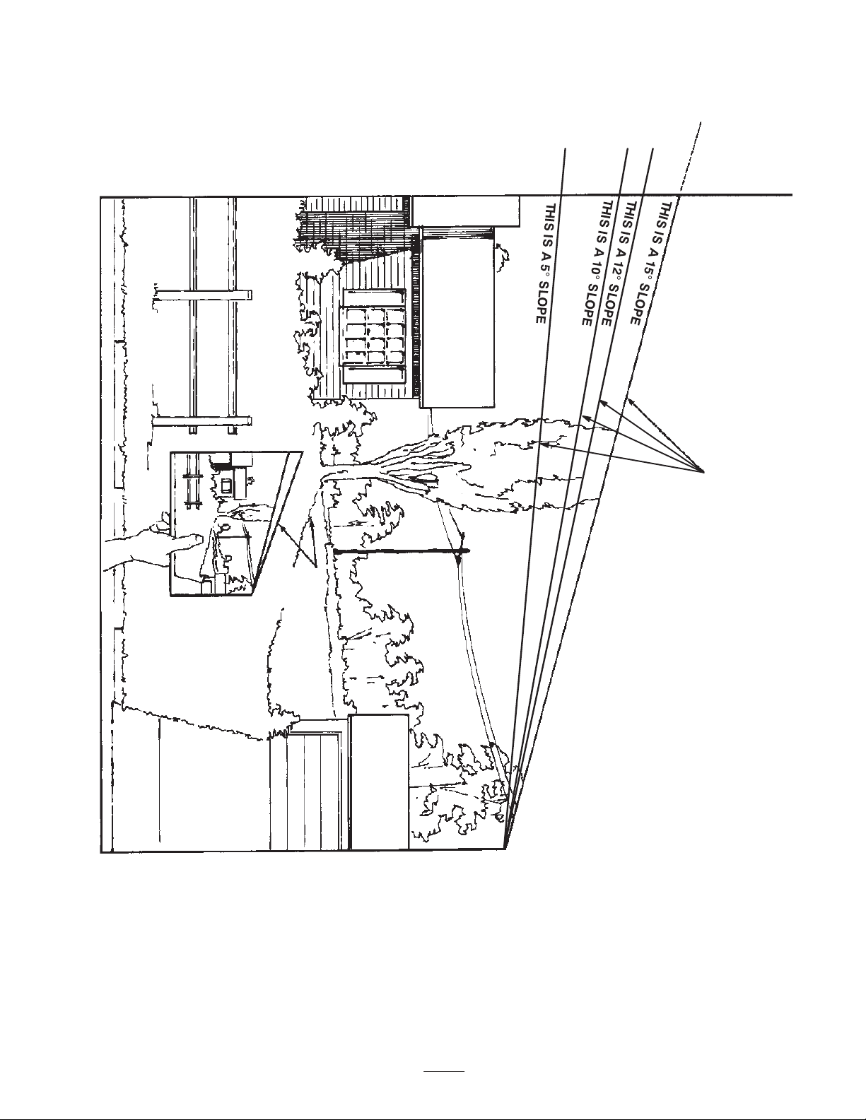
Slope Chart
ALIGN THIS EDGE WITH A VERTICAL SURFACE
(TREE, BUILDING, FENCEPOST, POLE, ETC.)
FOLD ALONG APPROPRIATE LINE.
EXAMPLE: COMPARE
SLOPE WITH FOLDED
EDGE.
7
Page 8

8
Page 9
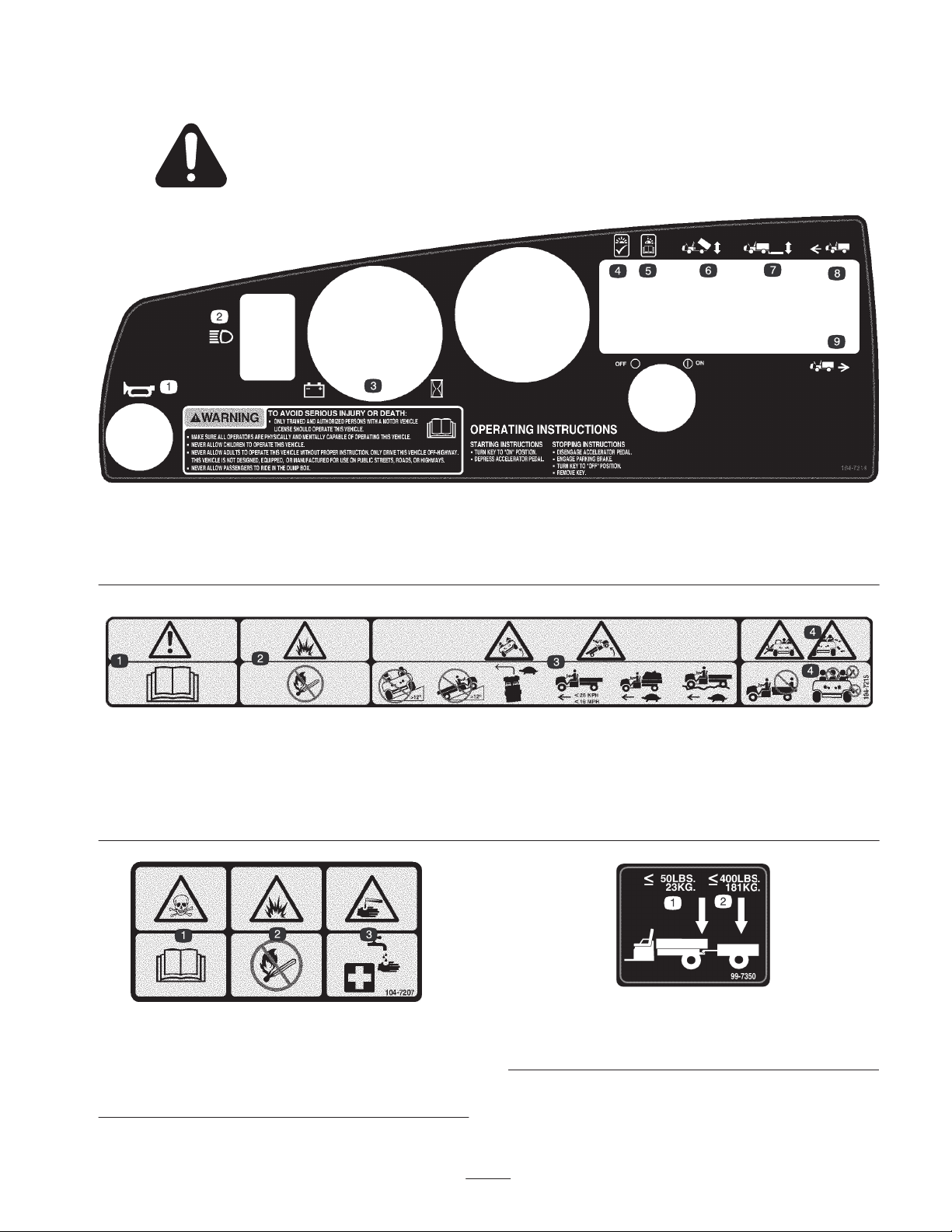
Safety and Instruction Decals
Safety decals and instructions are easily visible to the operator and are located near any area
of potential danger. Replace any decal that is damaged or lost.
1. Horn
2. Headlights
3. Battery/hour meter
4. Light on, OK
104-7214
5. Light blinking, read the
Operator’s Manual.
6. Cargo bed lift
7. Rear lift
8. Forward
9. Reverse
104-7215
1. Warning—read the Operator’s Manual.
2. Explosion hazard—no fire, open flames, or smoking.
3. Tipping hazard—do not drive the vehicle on a slope greater than 12 degrees; drive slowly when turning, when carrying a full or heavy load,
and when driving on rough terrain; keep the vehicle speed under 16 mph (26 kph).
4. Falling and arm/leg injury hazards—do not carry passengers in the cargo bed and keep arms and legs inside of the vehicle at all times.
99-7350
104-7207
1. Poison hazard—read the Operator’s Manual.
2. Explosion hazard—no fire, open flames, or smoking.
3. Caustic liquid/chemical burn hazard—to perform first aid, flush
with water.
1. Maximum tongue weight
is 50 lb. (23 kg)
2. Maximum trailer weight is
400 lb. (181 kg)
9
Page 10
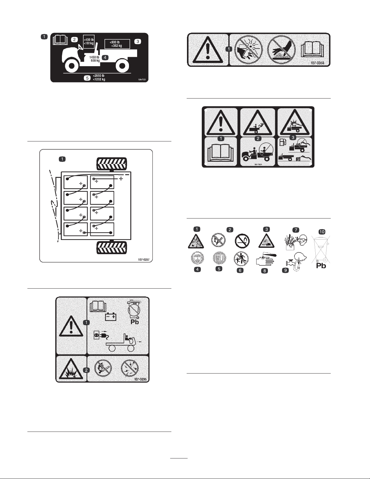
104-7131
1. Read the Operator’s Manual.
2. The maximum combined operator and passenger weight is
400 lb. (181 kg.).
3. The maximum cargo weight is 800 lb. (362 kg).
4. The base weight of the vehicle is 1450 lb. (658 kg).
5. The maximum gross vehicle weight is 2650 lb. (1202 kg).
107-0356
1. Warning—Do not touch moving objects, fan; do not touch the
hot surfaces; read the Operator’s Manual.
99-7954
1. Warning—read the Operator’s Manual.
2. Falling hazard—do not carry passengers in the cargo bed.
3. Explosion hazard, static discharge into fuel container—do not
fill fuel containers in the cargo bed; place fuel containers on the
ground before filling.
107-0257
1. Battery schematic
107-0295
1. Warning—Read the Operator’s Manual for more information on
batteries; batteries contain lead, do not discard; disconnect the
power cord from power source before driving vehicle.
2. Explosion hazard—No fire, open flames, or smoking; avoid
sparks.
Battery Symbols
Some or all of these symbols are on your battery.
1. Explosion hazard
2. No fire, open flames, or
smoking.
3. Caustic liquid/chemical
burn hazard
4. Wear eye protection
5. Read the Operator’s
Manual.
6. Keep bystanders a safe
distance from the battery.
7. Wear eye protection;
explosive gases can
cause blindness and
other injuries
8. Battery acid can cause
blindness or severe
burns.
9. Flush eyes immediately
with water and get
medical help fast.
10. Contains lead; do not
discard.
10
Page 11

Specifications
Note: Specifications and design are subject to change without notice.
Base weight
Rated capacity
(on level ground)
Maximum gross vehicle
weight (GVW)
(on level ground)
Maximum cargo capacity
(on level ground)
Tow capacity:
Standard Hitch Tongue weight 50 lb (23 kg) Maximum trailer weight 400 lb (182 kg)
Heavy Duty Hitch Tongue weight 100 lb (45 kg) Maximum trailer weight 800 lb (363 kg)
Overall width 60 in (152.4 cm)
Overall length 119 in (302.3 cm)
Ground clearance 9-1/4 in (23.5 cm) at the front with no load or operator
Wheel base 81 in (205.7 cm)
Wheel tread
(center line to center line)
Cargo box length
Cargo box width
Cargo box height 10 in (25.4 cm) inside
Dry 1450 lb (658 kg)
1200 lb (544.5 kg) total, including 200 lb (90.7 kg) operator and 200 lb (90.7 kg)
passenger, load, trailer tongue weight, gross trailer weight, accessories, and
attachments
2650 lb (1202 kg) total, including all of the weights listed above
800 lb (362 kg) total, including trailer tongue weight and gross trailer weight
49 in (124.5 cm) in the front
48-1/4 in (122.6 cm) in the rear
46 in (116.8 cm) inside
51 in (129.5 cm) outside
49 in (124.5 cm) inside
54 in (137.2 cm) outside
Optional Equipment
The Toro Company has optional equipment and accessories
that you can purchase separately and install on your
vehicle. Contact your Authorized Service Dealer for a
complete list of optional equipment that is currently
available for your vehicle.
11
Page 12

Setup
Note: Determine the left and right sides of the vehicle from the normal operating position.
Loose Parts
Note: Use the chart below to verify that all parts have been shipped.
Description
Charger
Key 2 Use in the On/Off switch.
Supervisor Speed Limit Switch Key 2 Use in the supervisor speed limit switch.
Operator’s Manual 1 Read before operating the vehicle.
Operator Video 1 Watch before operating the vehicle.
Parts Catalog 1 Use for ordering replacement parts.
Registration Card 1 Complete and return to Toro.
Predelivery Inspection Form 1 Complete and file in your customer history portfolio.
1
Refer to the Parts Manual for the available power cords for the voltage used in the region or country where operating the charger. Contact
your Authorized Toro Dealer to obtain the appropriate power cord.
1
Checking the Tire Pressure
Check the tire pressure every 8 hours or daily to ensure
proper levels.
The air pressure range in the front and rear tires is 8–22 psi
(55–152 kPa).
The air pressure needed is determined by the payload
carried. Lower air pressure will provide less compaction, a
smoother ride, and fewer tire marks. Lower pressure should
not be used for heavy payloads at high speeds.
Higher pressures should be used for heavier payloads at
higher speeds. Do not exceed the maximum pressure.
Setting the Charger Voltage
Qty. Use
1 Setting the charger voltage.
Always use the appropriate power cord for the power outlet
of the country or region charging will occur. Contact your
Authorized Toro Dealer to obtain the correct power cord if
necessary.
4
240 V
220 V
200 V
2
1
Important The incorrect voltage setting on the battery
charger can impair function and damage the charger.
Always make sure the charger voltage setting matches the
voltage used to power the charger.
1. Locate the voltage selector on the rear of the charger
(Fig. 2).
2. Adjust the voltage setting by moving the switch on the
voltage selector upward or downward to change the
voltage setting (Fig. 2).
The setting is displayed in the window above the selector.
Note: Use the 100V setting for voltages ranging from 100V
to 120V.
1. Voltage selector
2. Voltage setting window
3. Switch
12
100-120 V
3
m–7914
Figure 2
Rear of charger
4. Voltages by switch
position
Page 13

Operation
Note: Determine the left and right sides of the vehicle from
the normal operating position.
Think Safety First
Carefully read all of the safety instructions and decals in
the safety section. Knowing this information could help
you or bystanders avoid injury.
Controls
Accelerator Pedal
The accelerator pedal (Fig. 3) gives you the ability to vary
ground speed of the vehicle. Pressing the pedal when the
On/Off switch is on starts the motor. Pressing the pedal
farther increases ground speed. Releasing the pedal will
slow the vehicle and the motor will stop running.
3
Parking Brake
The parking brake is a small plate at the top of the brake
pedal (Fig. 3). Whenever you stop the vehicle, engage the
parking brake to prevent accidental movement of the
vehicle. To engage the parking brake, step on the brake
pedal firmly and roll forward with the top of your foot. To
disengage, press the accelerator or brake pedal. If the
vehicle is parked on a steep grade, apply the parking brake
and place blocks on the downhill side of the wheels.
On/Off Switch
The On/Off switch (Fig. 4), used to activate the electrical
systems of the vehicle, has two positions: Off and On.
Rotate the key clockwise to the On position to allow
operation of the vehicle and accessories. After stopping the
vehicle, rotate the key counterclockwise to the Off position.
Remove the key before leaving the vehicle.
3
4
6
5
8
7
2
m–6203
1. Accelerator pedal
2. Brake pedal
1
Figure 3
3. Parking brake
Brake Pedal
Use the brake pedal to stop or slow the vehicle (Fig. 3).
Caution
Brakes can become worn or can be misadjusted
resulting in personal injury.
If brake pedal travels to within 1 inch of the
vehicle floor board, the brakes must be adjusted or
repaired.
2
Figure 4
1. On/Off switch
2. Horn button
3. Light switch
4. Battery/hour meter
1
5. Vehicle status light
6. Power cargo bed switch
7. Rear lift switch
8. Vehicle direction switch
m–6219
Horn Button
Press the horn button to activate the vehicle horn (Fig. 4).
Battery/Hour Meter
The battery/hour meter provides you with an indication of
how much charge is contained in the batteries (Fig. 4 and 8)
and the number of operating hours on the vehicle. The
battery meter is located at the top of the LCD screen.
When the vehicle batteries are fully charged, ten bars
extend from the 0 to the 1 position. As the charge is used,
bars disappear starting on the right side. For detailed
information on the battery meter, refer to Understanding
and Using the Battery System; page 15.
The hour meter is located at the bottom of the LCD screen.
It logs operating hours whenever the key is in the On
position and the vehicle is in motion.
13
Page 14

Vehicle Direction Switch
Passenger Hand Holds
Use this switch (Fig. 4) to toggle between forward and
reverse operation.
Vehicle Status Light
This light communicates the status of the vehicle as
determined by the on board computer. Always check this
light when you turn the On/Off switch to the On position
(Fig. 4). The light flashes at various intervals for different
problems and events. When there are no problems and the
vehicle is operational, the light is on. If the light blinks,
refer to Troubleshooting, page 31, for a description of the
flash codes.
Light Switch
Use this switch to turn the headlights on and off (Fig. 4).
Cargo Bed Lift Switch (Optional)
Use this switch to raise and lower the cargo bed (Fig. 4).
Rear Lift Switch (Optional)
Use this switch to raise and lower the rear lift (Fig. 4).
The passenger hand holds are located on the right side of
the dash panel and at the outside of each seat (Fig. 6).
2
1
m–4887
Figure 6
1. Passenger hand hold 2. Hip restraint
Pre-Operating Checks
Check the following items each time you begin using the
vehicle for the day:
• Check the tire pressure.
• Check the brake pedal operation.
• Check to see that the lights are working.
Supervisor Speed Limit Switch
The supervisor speed limit switch, located under the cup
holder (Fig. 5), has two positions: Off and On. Rotate the
key clockwise to the On position to limit the maximum
vehicle speed to a factory setting of 12 mph (19 kph).
Rotate the key counterclockwise to the Off position to
restore the maximum speed of the vehicle.
1
m–7436
Figure 5
1. Supervisor speed limit switch
• Turn the steering wheel to the left and right to check
steering response.
• Check for loose parts and any other noticeable
malfunctions. Make sure the vehicle is off and all
moving parts have stopped before checking for loose
parts and other malfunctions.
If any of the above items are not correct, notify your
mechanic or check with your supervisor before taking the
vehicle out for the day. Your supervisor may want you to
check other items on a daily basis, so ask what your
responsibilities are.
Operating the Vehicle
1. Disconnect the battery charger.
2. Sit in the operator’s seat, insert the key into the On/Off
switch, and rotate the key clockwise to the On position.
3. Move the vehicle direction switch button to the desired
position.
4. Slowly step on the accelerator pedal to drive the
vehicle.
Note: The parking brake will automatically disengage
when you press the accelerator pedal.
14
Page 15

Important When driving up slopes, do not stop the
vehicle using the accelerator pedal to hold it in place. This
will damage the motor. Instead use the brake or parking
brake to stop the vehicle and hold it in place.
m–7220
Stopping the Vehicle
To stop the vehicle, remove your foot from the accelerator
pedal and slowly press the brake pedal.
Note: Stopping distance may vary depending on the vehicle
load and speed.
Parking the Vehicle
1. Engage the parking brake and rotate the On/Off key to
Off.
2. Remove the key from the switch to prevent accidental
starting.
Understanding and Using the
Battery System
Understanding Deep Cycle Batteries
The vehicle contains 8 deep cycle, lead-acid batteries which
supply power to the motor and accessories. A deep cycle
battery is not the same as an automobile battery. An
automobile battery is designed to provide a surge of power
to start the vehicle and moderate power to run the lights
and accessories when the engine if off or idling. The
alternator then continuously recharges it as the automobile
runs. As such, an automobile battery seldom drops below
90% of maximum charge level.
3
1
2
1. Battery capacity
2. Discharge/charge cycles
3. Break-in period (20 to
50 cycles)
After the break-in period, the battery will maintain a high
capacity for many cycles. The number of cycles a battery
will perform is dependant on the following:
• Battery maintenance—improper maintenance will
severely reduce the life of the batteries.
• Depth of discharge between charge cycles—the deeper
the batteries are discharged on a regular basis
between charges, the less life they will have.
• Recharge frequency—charge the batteries whenever
they are not in use. Fully discharging the batteries
will damage them and reduce their life.
At the end of the battery life, the coating on the lead plates
begins to deteriorate, causing the batteries to rapidly lose
electric capacity.
4
Figure 7
4. Prime battery life
5. End of battery life
5
A deep cycle battery is designed to be a primary power
source to provide a sustained output. Deep cycle batteries
are typically discharged as low as 20% to 30% of the
maximum charge level. A discharge this low is considered
a deep discharge.
Lead acid batteries produce electricity through a chemical
reaction between coated lead plates and sulfuric acid.
Charging a battery reverses the chemical reaction, allowing
the battery to once again produce electricity.
A battery is a perishable item that has a limited life time
(Fig. 7). When a battery is new, it requires a break-in period
to establish efficient electrical production. This break in
period usually requires 20 to 50 discharge/charge cycles.
15
Page 16

Using the Battery System
When your batteries are fully charged, the battery meter
will have ten bars showing from left to right (Fig. 8).
When only one bar is left, the warning light will begin
flashing and the vehicle will go into an energy saving mode
(Fig. 10). In this mode, the vehicle will only drive at 3 mph.
Recharge the batteries immediately to prevent serious
damage to them.
1
2
m–7222
Figure 8
1. Battery/hour meter 2. Charge indicator bars
As you use the vehicle, the bars will disappear as the
electrical capacity of the batteries is used.
When only 2 bars are left, the red warning light on the
meter will illuminate and the battery icon will begin
flashing on the screen (Fig. 9). This indicates that the
battery capacity is nearly drained and you should charge the
batteries as soon as possible to prevent battery damage.
If the batteries become fully discharged, the vehicle will
shut down. Do not allow the batteries to become fully
discharged.
Important To obtain maximum battery life, always
charge the batteries when there are 2 or more bars visible
on the screen. Depleting the batteries lower than 2 bars,
especially on a regular basis, will reduce the life of the
batteries.
2
1
m–7225
Figure 10
1. Battery icon 2. Warning light—flashing
1
m–7224
Figure 9
1. Battery icon 2. Warning light—on
Operating the Cargo Box
2
Raising the Box
Warning
Driving the vehicle with the cargo box raised may
cause the vehicle to tip or roll easier. The box
structure may become damaged if the box is raised
for an extended period of time while operating the
vehicle.
• Only operate the vehicle when the cargo box is
down.
• After a load has been dumped, lower the cargo
box.
16
Page 17

1. Lift the lever on either side of the box and lift the box
up (Fig. 11).
1
Adjusting the Box Latches
If the box does not latch tightly, vibrating up and down as
you drive the vehicle, you can adjust the latch posts to
make the latches fit snuggly.
1. Loosen the nut on the end to the latch post (Fig. 13).
2
m–7437
Figure 11
1. Lever
2. Pull the prop rod into the detent slot, securing the box
(Fig. 12).
2
m–7438
Figure 12
1. Prop rod 2. Detent slot
Lowering the Box
3
1
m–7439
Figure 13
1. Latch
2. Nut
1
2. Turn the latch post clockwise until it is snug against the
latch and then tighten the nut (Fig. 13).
3. Latch post
3. Repeat this procedure for the latch on the other side of
the vehicle.
Opening and Closing the Tailgate Latches
1. To open the tailgate latches, lift the latch handles up
(Fig. 14). The latches will spring out toward the center
of the tailgate. Slowly lower the tailgate.
Note: You may need to push the end of the tailgate in
(especially if there is a load against the tailgate) before the
latches will spring toward the center of the tailgate and
release.
Warning
The weight of the box may be heavy. Hands or
other body parts could be crushed.
Keep hands and other body parts clear when
lowering the box.
Pull the prop rod out of the detent slot and lower the box
until it latches in place.
1
m–5334
Figure 14
1. Tailgate latch
17
Page 18

2. To close the tailgate latches, lift the handles upward and
slide them toward the outside of the vehicle.
3. Push the latch handles downward to secure the latch and
tailgate.
Breaking-in a New Vehicle
To provide proper performance and long vehicle life,
follow these guidelines for the first 100 operating hours:
New deep-cycle batteries do not reach their maximum
charge capacity until they have been cycled 20 to 50 times
(i.e., charged and discharged). Therefore, you will notice
that new batteries will not run as long as batteries that have
been broken-in. This is normal and not a cause for
concern.
• Avoid hard braking situations for the first several hours
of new vehicle break-in operation. New brake linings
may not be at optimum performance until several hours
of use has caused the brakes to become burnished
(broken-in).
• Refer to the Maintenance section for any special low
hour checks.
• Check the front suspension positioning and adjust it if
necessary; refer to Adjusting the Front Suspension,
page 26.
Transporting the Vehicle
For moving the vehicle long distances, a trailer should be
used. Make sure that the vehicle is secured to the trailer.
Refer to Figures 15 and 16 for the location of the tie down
points.
Caution
Loose seats may fall off of the vehicle and trailer
when transporting and land on another vehicle or
become an obstruction on the road.
Remove the seats or make sure that the seats are
securely fastened in the detents.
1
1. Tie down points
m–7440
Figure 15
1
Loading the Cargo Box
The capacity of the cargo box is 13 ft3 (0.37 m3). The
amount (volume) of material that can be placed in the box
without exceeding the vehicle load ratings can vary greatly
depending on the density of the material. For example, a
level box of wet sand weighs 1500 lb (680 kg), which
greatly exceeds the load rating.
See the table below for load volume limits with various
materials:
Approximate
Material
Gravel
Dry
Wet
Sand
Dry
Wet
Wood 45 Full
Bark <45 Full
Earth, packed 100 1/2 full
Density
(lb./ft.
95
120
90
120
max. cargo box
3
capacity (on level
)
ground)
1/2 full
1/3 full
1/2 full
1/3 full
Towing the Vehicle
In case of an emergency, the vehicle can be towed at a slow
speed for a short distance. However, we do not recommend
this as a standard procedure.
Important Towing the vehicle more than 5 mph will
damage the motor.
Warning
Towing at excessive speeds could cause a loss of
steering control, resulting in personal injury.
Never tow the vehicle faster than 5 MPH.
Towing the vehicle is a two person job (one needs to drive
the towing vehicle and one needs to steer this vehicle). If
the vehicle must be moved a considerable distance,
transport it on a truck or trailer; refer to Transporting the
Vehicle, page 18.
1. Turn off the On/Off switch and remove the key.
2. Affix a tow line to the tongue on the front frame
member (Fig. 16).
3. Release the parking brake.
18
Page 19

m–7441
Figure 16
1. Towing tongue and tie down point
Towing a Trailer
The vehicle is capable of pulling trailers. Two types of tow
hitches are available for the vehicle, depending on your
application. Contact your Authorized Toro Distributor for
details.
When hauling cargo or towing a trailer, do not overload
1
your vehicle or trailer. Overloading can cause poor
performance or damage to the brakes, axle, motor,
transaxle, steering, suspension, body structure, or tires.
Always load a single axle trailer with 60% of the cargo
weight in the front of the trailer. This places approximately
10% of the Gross Trailer Weight (GTW) on the tow hitch
of the vehicle.
The maximum cargo load shall not exceed 800 lb (362 kg),
including the GTW and tongue weight. For example, if the
GTW = 200 lb and tongue weight = 50 lb, then the
maximum cargo load = 550 lb.
To provide adequate braking and traction, always load the
cargo box when trailering. Do not exceed the GTW limits.
Avoid parking a vehicle with a trailer on a hill. If you must
park on a hill, engage the parking brake and block the
trailer tires.
Maintenance
Recommended Maintenance Schedule
Maintenance Service
Interval
When not in use • Charge the batteries.
Every 8 hours • Check the tire pressure.
After first 20 hours • Check the front wheel toe-in at the proper ride height.
Every 25 hours
Every 100 hours
Every 200 hours • Check the brake cable adjustments.
Maintenance Procedure
• Check the battery electrolyte level.
• Check the battery cable connections.
• Clean the batteries.
• Lubricate all grease fittings.
• Inspect the brake and parking brake.
• Inspect the condition and wear of the tires.
• Torque the wheel lug nuts.
• Check the front suspension toe-in and ride height.
• Check the transaxle oil level.
19
Page 20

Duplicate this page for routine use.
For the week of:
Maintenance Check Item
Mon. Tues. Wed. Thurs. Fri. Sat. Sun.
Charge the batteries.
Check the brake and parking brake
operation.
Check any unusual operating noises.
Check the tire pressure.
Check for fluid leaks.
Check the instrument operation.
Check the accelerator operation.
Check ride height and toe-in.
Lubricate all grease fittings.
1
Touch up any damaged paint.
1
Immediately after every washing, regardless of the interval listed
Notation for Areas of Concern
Inspection performed by:
Item Date Information
1
2
3
4
5
6
7
8
9
10
11
12
13
Note: Determine the left and right sides of the vehicle from the normal operating position.
Warning
The bed must be raised to perform some routine maintenance. The bed could fall and injure
persons that are underneath it.
Remove any load material from bed before working under raised bed.
20
Page 21

If you leave the key in the On/Off switch, someone could accidently start the vehicle and
seriously injure you or other bystanders.
Remove the key from the On/Off switch before you do any maintenance.
Heavy Duty Operation
Important If the vehicle is subjected to any of the
conditions listed below, maintenance should be performed
twice as frequently:
• Desert operation
• Cold climate operation (below 32 degrees F)
Caution
• Trailer towing
• Frequent operation on dusty roads
• Construction work
• After extended operation in mud, sand, water, or similar
dirty conditions, have your brakes inspected and
cleaned as soon as possible. This will prevent any
abrasive material from causing excessive wear.
• Under frequent heavy duty operating conditions,
lubricate all grease fittings.
Jacking the Vehicle
Whenever the motor is run for routine maintenance and/or
diagnostics, the rear wheels of the vehicle should be 1 inch
(25 mm) off of the ground with the rear axle supported on
jack stands.
Danger
A vehicle on a jack may be unstable and slip off of
the jack, injuring anyone beneath it.
m–7442
1. Front jacking point
1
1. Rear jacking points
1
Figure 17
m–7443
Figure 18
1
• Do not start the vehicle while the vehicle is on a
jack.
• Always remove the key from the switch before
getting off of the vehicle.
• Block the tires when the vehicle is on a jack.
The jacking point at the front of the vehicle is on the front
of the frame behind the towing tongue (Fig. 17). The
jacking point at the rear of the vehicle is under the axle
tubes (Fig. 18).
21
Page 22

Maintaining the Batteries
Warning
2
Battery terminals or metal tools could short
against metal vehicle components causing sparks.
Sparks can cause the battery gasses to explode,
resulting in personal injury.
• When removing or installing the battery, do not
allow the battery terminals to touch any metal
parts of the vehicle.
• Do not allow metal tools to short between the
battery terminals and metal parts of the vehicle.
• Always keep the battery retainers in place to
protect and secure the batteries.
Warning
CALIFORNIA
Proposition 65 Warning
Battery posts, terminals, and related accessories
contain lead and lead compounds, chemicals
known to the State of California to cause cancer
and reproductive harm. Wash hands after
handling.
1
4
1. Voltage selector
2. Voltage setting window
3. Switch
Locate the voltage selector on the rear of the charger.
Adjust the voltage setting by moving the switch on the
voltage selector upward or downward to change the voltage
setting (Fig. 19) The setting is displayed in the window
above the selector.
240 V
220 V
200 V
100-120 V
3
m–7914
Figure 19
Rear of charger
4. Voltages by switch
position
Cleaning the Batteries
Clean the batteries every day before use.
1. Ensure that all of the battery caps are tight.
2. Use a paper towel to clean the batteries.
3. If the battery terminals are corroded, clean them with a
solution of four parts water and one part baking soda.
Also, clean the posts and cable clamps with a post and
clamp cleaner. The posts and clamps should have a
bright metallic shine.
4. Apply a light coating of Toro battery terminal protector.
Setting the Charger Voltage
Important The incorrect voltage setting on the battery
charger can impair function and damage the charger.
Always make sure the charger voltage setting matches the
voltage used to power the charger.
Note: Use the 100V setting for voltages ranging from 100V
to 120V.
Always use the appropriate power cord for the power outlet
of the country or region charging will occur. Contact your
Authorized Toro Dealer to obtain the correct power cord if
necessary.
Charging the Batteries
A charger is supplied with the vehicle. Always keep the
charger in a dry location. For maximum battery life, charge
the batteries whenever you are not using the vehicle.
Depending on how discharged the batteries are, it may take
up to 16 hours to charge the batteries to full capacity.
Important Lead-acid batteries do not develop a charge
memory and do not need to be fully discharged before
charging them. Fully discharging the batteries may
damage them. Charge the batteries whenever the vehicle
gets low on power and any time it is not in use; refer to
Using the battery System, page 16.
22
Page 23

Warning
Charging the battery produces gasses that can
explode.
Never smoke near the batteries and keep sparks
and flames away from them.
4. Replace the filler caps on all batteries.
5. Charge the batteries for 16 hours; refer to Charging the
Batteries, page 22.
6. Remove the filler caps from each battery.
7. Add just enough distilled water to bring the electrolyte
level to 1/8 inch (3 mm) below the bottom of each fill
well (Fig. 20).
1. Position the vehicle in a well ventilated area near a
115 vac, 15 amp power outlet.
2. Connect the charger cord to the charging receptacle on
the vehicle (located on the panel between the seats).
3. Plug the charger power cord into a 115 vac, 15 amp
power outlet.
While the batteries are charging, the green light on the
charger will blink on and off. When the batteries are
fully charged, the green light stops blinking and stays
on.
4. Disconnect the cord from the power outlet.
5. Disconnect the charger from the vehicle.
Important Do not carry the charger on the vehicle.
Excessive or prolonged jarring may damage it.
Adding Water to the Batteries
Check the electrolyte level and add water if needed every
25 operating hours or, if the vehicle is in storage, every 30
days. Use only clean, distilled water to fill the batteries.
Danger
2
4
1
Figure 20
1. Battery plates
2. Filler cap
Important Do not overfill the battery. Electrolyte will
overflow onto other parts of the vehicle and severe
corrosion and deterioration may result. Also, overfilling
the battery will reduce the life of the battery.
8. Replace the filler caps on all batteries.
3. Electrolyte level
4. Battery terminal
3
Battery electrolyte contains sulfuric acid which is a
deadly poison and causes severe burns.
• Do not drink electrolyte and avoid contact with
skin, eyes or clothing. Wear safety glasses to
shield your eyes and rubber gloves to protect
your hands.
• Fill the batteries where clean water is always
available for flushing the skin.
• Never add acid to a battery.
1. Raise the cargo bed, turn the key off, and remove it.
2. Remove the filler caps from each battery.
3. If the electrolyte is not over the top of the plates in each
battery cell, add just enough distilled water to cover the
plates.
Replacing Used Batteries
When the vehicle begins to show a loss of range or when
the length of the discharge/charge cycle is significantly
reduced, the batteries are probably getting old and losing
their ability to hold a charge. Take the vehicle to an
Authorized Service Dealer and have them test the batteries
to determine whether the batteries need to be replaced. The
Dealer can then replace the batteries for you. If you wish
to replace the batteries yourself, use the following
procedure:
1. Raise the cargo bed, turn the key off, and remove it.
2. Disconnect the long, black, main negative lead running
from the bank of batteries to the vehicle from the
battery post (Fig. 21).
23
Page 24

Warning
6. Remove all of the batteries and recycle them according
to your local codes.
Incorrect battery cable routing could damage the
vehicle and cables causing sparks. Sparks can
cause the battery gasses to explode, resulting in
personal injury.
• Always ensure the battery polarity when
making connections.
Caution
Batteries can give you a powerful electrical shock.
• Use tools with plastic handles or wrap the
handles of metal tools with electrical tape.
• Be careful not to contact both a positive
terminal and a negative terminal at the same
time.
7. Install new batteries in the places vacated by the old
batteries
Note: Pay attention to the battery polarity when
installing the new batteries (Fig. 21).
8. Install the battery retainers and torque the nuts to 150 to
200 in-lb (17 to 22 N⋅m).
9. Connect the batteries together with the battery cables
removed previously, as illustrated in Figure 21.
10. Connect the long, red, main positive lead between the
bank of batteries and the vehicle (Fig. 21).
11. Connect the long, black, main negative lead between
the bank of batteries and the vehicle (Fig. 21).
12. Torque the nuts securing all battery cables to 120 to 180
inch-lb (13.5 to 21 N⋅m).
13. Coat the battery terminals with Toro battery terminal
protector.
14. Ensure that the rubber boots on each battery cable are
securely seated over the battery terminals.
Storing the Batteries
Figure 21
3. Remove the long, red, main positive lead running from
the bank of batteries to the vehicle from the battery post
(Fig. 21).
4. Disconnect all of the battery leads from the batteries.
5. Remove the battery retainers located between the
batteries.
Charge the batteries fully before placing the vehicle into
storage. Plug the charger into a wall outlet while the vehicle
and batteries are in storage. Leave the charger plugged into
a wall outlet and charging receptacle during storage to
ensure that the batteries stay charged and do not freeze;
otherwise, charge the batteries at least once every 3 months.
Greasing the Vehicle
Lubricate all bearings and bushings after every 100 hours
or once a year, whichever occurs first. Grease them more
frequently when using the vehicle for heavy-duty
operations.
Grease Type: No. 2 General Purpose Lithium Base Grease
Where to Add Grease
The grease fitting locations are at the four tie rod ends
(Fig. 22) and the two king pins (Fig. 23).
1. Wipe the grease fitting clean so that foreign matter
cannot be forced into the bearing or bushing.
2. Pump grease into the bearing or bushing.
24
Page 25

3. Wipe off excess grease.
Adjusting the Brake Pedal
Adjust the brake if the parking brake does not hold, the
brake pedal travel is excessive, or braking power is not
sufficient when the brake pedal is depressed. Check the
adjustment every 200 hours.
1. Turn the ignition off and remove the key.
2. Check the brake cables at the brake equalizer (located
under the dash) and determine approximately how far
up the brake rod the equalizer needs to travel so that
there is no slack in the cables (Fig. 24).
1
m–5320
Figure 22
m–5324
Figure 23
Servicing the Brakes
Inspecting the Brakes
Brakes are a critical safety component of the vehicle. As
with all safety components, they should be closely
inspected at regular intervals to ensure optimum
performance and safety. The following inspections should
be done every 100 hours:
• Inspect the brake shoes for wear or damage. If the
lining (brake pad) thickness is less than 1/16 inch
(1.6 mm), the brake shoes should be replaced.
2
3
4
6
7
5
7
m–6288
Figure 24
1. Clevis pin
2. Brake lever
3. Brake rod clevis
4. Brake rod
5. Brake equalizer
6. Spring
7. Brake cable
3. Remove the hairpin cotter and clevis pins securing the
brake rod clevis (Fig. 24).
4. Disconnect the spring from the end of the brake rod
(Fig. 24).
5. Press the brake pedal down fully to raise the brake
lever.
6. Thread the brake rod in or out of the brake equalizer as
needed to remove the slack from the brake cables
(Fig. 24). Do not overtighten the cables.
7. Install the spring into the hole in the brake rod (Fig. 24).
• Inspect the backing plate and other components for
signs of excessive wear or deformation. If any
deformation is found, the appropriate components must
be replaced.
8. Connect the clevis on the brake rod to the brake lever
using the clevis pin and hairpin cotter removed
previously (Fig. 24).
9. Ensure that there is some free play in the brake pedal
before the brake engages. If not, repeat this procedure
until there is.
25
Page 26

Inspecting the Tires
Check the tire condition at least every 100 hours of
operation. Operating accidents, such as hitting curbs, can
damage a tire or rim and also disrupt wheel alignment, so
inspect tire condition after an accident.
Check the wheels to ensure that they are mounted securely.
Torque the center bolts on the front wheels to 135–165 ft-lb
(183–224 N⋅m) and the front and rear lug nuts to
45–65 ft-lb (61–88 N⋅m).
Adjusting the Front
Suspension
The ride height of each side of the vehicle can be adjusted
separately. The ride height should be 8-3/4 to 9-1/2 inch
(22.2–24.1 cm) with the following parameters:
• The tire pressure should be at 12 psi (83 kPa).
• The vehicle should be driven back and forth a few times
to relax the A-arms.
• Measure the ride height with the wheels facing straight
ahead and a 175–225 lb (79–102 kg) operator in the
driver’s seat.
Note: The driver should drive up to the measurement
area and stay seated in the vehicle while the
measurement is being taken.
• Measure the ride height on a flat surface, from the
bottom of the front tongue to the ground.
1. Jack the front end of the vehicle off of the ground; refer
to Jacking the Vehicle, page 21.
2. Remove the travel limiting bolt (Fig. 25).
2
3
2
1. Travel limiting bolt
2. Centering bolt
5. Rotate the front A-arm to the desired position (refer to
the note below) and replace the ride height adjustment
bolt (Fig. 25).
Note: The A-arms are made with rubber and have different
spring rates. Because of the different spring rates, the
A-arms come adjusted from the factory based on that
spring rate. Generally the adjustment bolts will be installed
in hole number 2, 3, or 4 (Fig. 26) and it may be different
from the left side (driver side) to the right side (passenger
side). If the A-arms look like they are sagging, then they
should be adjusted to the next higher number (Fig. 26).
Each hole equals about 3/4 inch (19 mm) of adjustment at
the wheel. You will also need to do this if you are adding
heavy attachments or carrying heavy loads often.
1
m–7444
Figure 25
3. Ride height adjustment
bolt
3. Loosen the centering bolts in the front A-arm (Fig. 25).
4. Remove the ride height adjustment bolt (Fig. 25).
1
Figure 26
1. Left-hand A-arm
6. Torque the ride height adjustment bolt to 135–165 ft-lb
(183–224 N⋅m).
7. Replace the travel limiting bolt (Fig. 25).
26
m–5640
Page 27

Note: The vehicle may need to be lowered to the ground on
that side to install the bolt.
8. Tighten and torque the centering bolts to 240–290 ft-lb
(325–393 N⋅m).
height. Use the same fixture or alignment gauge to
accurately measure the front of the front tires at axle
height (Fig. 27).
9. Check the ride height at the front tongue per the
dimensions and parameters given at the beginning of
this procedure.
Adjusting the Front Wheel
Toe-In
Check the front wheel toe-in after every 100 operating
hours, or annually, whichever occurs first.
The toe-in should be 1/8–5/8 inch (3–16 mm) with the
following parameters:
• The tire pressure should be at 12 psi (83 kPa).
• The ride height should be correct before setting the
toe-in; refer to Adjusting the Front Suspension, page 26.
• The vehicle should be driven back and forth a few times
to relax the A-arms.
• Measure the toe-in with the wheels facing straight
ahead and a 175–225 lb (79–102 kg) operator in the
driver’s seat.
Note: The driver should drive up to the measurement
area and stay seated in the vehicle while the
measurement is being taken.
If the vehicle will be run with medium to heavy loads most
of the time, set the toe-in on the high side of the
recommended amount. If it is going to be run with a light
load most of the time, set the toe-in on the low side of the
recommended amount.
6
1
5
4
2
3
52 inch
(132 cm)
5
m–5639
Figure 27
1. Tire center line—back
2. Tire center line—front
3. Axle center line
4. Fixture
5. Axle center line distance
6. 6 inch (15 cm) ruler
3. If the measurement does not fall within the specified
range (refer to the dimensions and parameters at the
beginning of this procedure),
loosen the jam nuts at
both ends of the tie rods (Fig. 28).
4. Rotate both tie rods to move the front of the tire inward
or outward.
1
2
1
1. Ensure that the front suspension is adjusted properly;
refer to Adjusting the Front Suspension, page 26.
Adjust if necessary.
2. Measure the distance between both of the front tires at
the axle height at both the front and rear of the front
tires (Fig. 27). A fixture or alignment gauge is needed
for the rear measurement of the front tires at axle
m–5320
Figure 28
1. Jam nut 2. Tie rod
5. Tighten the tie rod jam nuts when the adjustment is
correct.
6. Ensure that there is full travel of the steering wheel in
both directions.
27
Page 28

Checking the Transaxle Oil
Level
Check the oil level in the transaxle at the rear of the vehicle
every 100 operating hours.
1. Park the vehicle on a level surface, set the parking
brake, and turn off and remove the key.
2. Remove the check bolt on the transaxle (Fig. 29).
The oil level should be even with the bottom of the
check hole.
2
1
m–7445
Figure 29
1. Transaxle 2. Check bolt
3. If the oil level is low, add 10w30 motor oil to the check
hole until it runs out the hole.
4. Replace the check bolt and torque it to 15 to 20 ft-lb (20
to 27 N⋅m).
1
2
m–7446
Figure 30
1. Vehicle Fuse 2. Accessories Fuse
Replacing the Headlights
Specification: Toro #104-7312, 28 volt
Note: The headlights are wired in series; therefore, when
one headlight burns out, neither will illuminate. If possible,
change both headlights at the same time.
1. Set the parking brake, turn the vehicle off, and remove
the key.
2. Reach beneath the dash and push the headlight out of
the hood.
Replacing the Fuses
There are 2 fuses in the electrical system. They are located
beneath the steering column (Fig. 30).
Vehicle
Accessories 10 amp
10 amp
3. Remove the screws attaching the wire harness to the
headlight.
4. Remove the rubber seal from around the headlight
(Fig. 31). Discard the headlight.
5. Align the notch on the inside of the seal with the notch
on the new headlight (Fig. 31). Slide the seal onto the
headlight until the seal is firmly in place.
28
Page 29

3
2
4
1
Figure 31
1. Rubber seal
2. Inside notch—align with
notch on headlight
3. Outside notch—align with
notch in hood
4. Headlight
6. Attach the headlight to the wire harness using the
previously removed screws.
7. Align the notch on the outside of the seal with the notch
in the hood. Push the headlight and seal into the hood
until it is firmly in place.
Note: Applying soapy water to the outside of the seal may
aid in sliding the seal into the hood.
Washing the Vehicle
The vehicle should be washed as needed. Use water alone
or with a mild detergent. A rag may be used, however the
hood will loose some of its luster.
Important Do not use high pressure water when
washing the vehicle. It may damage the electrical system,
loosen important decals, or wash away necessary grease at
friction points. Avoid excessive use of water, especially
near the control panel, motor, and batteries.
29
Page 30

Electrical Schematic
10 A
F3
PK
BU
R
FUSE HOLDER 218–489
10 AF2
98–8876
RUN
107–0348
IGNITION–SWITCH
OFF
98–8876
OR
104–7135
ACCESSORIES CONTACTOR
BATT. CHG.
INTERLOCK
CHARGER
BK
R/W
HOOK UP
SWITCH
(+)(–)
MAIN CONTACTOR
99–7407
ACCELERATOR
104–7136
B+
3 ACCELERATOR PEDAL
BU
(PEDAL NOT PUSHED IN)
107–0738
4 GA
10 GA
F1
A2
5 CHARGER
6 HIGH TEMP/LOW BATTERY
4 HI/LOW
NC
Y
BU/W
VIO/BK
MOTOR TEMP SENSOR
94–5245
BK
HI / LOW SPEED SWITCH
7 BACKUP ALARM
W/BK
(180 C)
6V x 8 (DEEP CYCLE)
104–7311
48V BATT ARRAY
(+)(–)
107–0741
104–7320
355 A
F1
FL2
FL1
107–0740
OR
FL3
364
BU/W
5
6
3
PROGRAMMER
12 45
2 FOR/REV
1 48 VDC INPUT
OR
3 (NC)
2 (NO)
4
1
95–8999
FORWARD/REVERSE
PORT
PK
Y
6 IGN +
8 (–)
7 FET OUT
5 SENSE B
HR–METER
INDICATOR
107–0260
STATE OF CHARGE
4 (+)
1 SENSE A
Y
3 HR ENABLE
2 SETUP +
R
1
2
BK
DRIVE MOTOR
FIELD F1 A2 ARMATURE
SEVCON
MILLIPAK
8 MAIN CONTACTOR
DIAGNOSTIC LED
107–0739
(+)(–) (+)(–)(+)(–) (+)(–)
104–7335
F2 A1
104–7337
CONTROLLER
9 DIAGNOSTIC LIGHT
10 ACCELERATOR POT
GN
T
104–7365
ACCELERATOR POT
104–7129
W
107–0737
10 GA
F2
11 PROGRAMMING
12 12 VDC OUTPUT (100 mA)
NC
CW
BN
+ 12V
(+)
(–)
BACKUP ALARM
HORN
94–5582
BK
4 GA
(+)(–) (+)(–)
107–0742
SPLICE
B–
A1
15
14
13
NC
16
NC
NC
NC
GY
W
BK
PROGRAMMING
107–0358
HORN
W
18–2830
HORN SWITCH
GE 4589
104–7312
GN
HEADLIGHTS, 24V
GE 4589
104–7312
OR
364
1
5
2
LIGHT SW
95–8999
BU
BK
+48 VDC
OPTIONS
B
A
30
Page 31

Troubleshooting
Check all b
d
The vehicle contains a computer that monitors the state of
the vehicle electrical systems. This computer
communicates the status of the vehicle to you through the
vehicle status light. When the vehicle is functioning
properly, the light will be on. When there is a problem, the
light flashes. The number of flashes changes depending on
the problem. The following table lists the various flash
patterns, the cause, and the steps you can take to resolve the
problem.
Status Light Flash Pattern
Always on The system is functioning properly. None
1 flash The computer programming
2 flashes The accelerator pedal was
3 flashes
4 flashes The line contactor is not
Cause Corrective Action
personality is out of range.
pressed when the On/Off key was
turned.
The power block has a short circuit
(MOSFET S/C).
A poor batter or power cable
connection.
responding to commands.
Turn the On/Off key to the Off
position, wait a few seconds, and
turn the On/Off key to the On
position. If the condition continues,
refer to your Authorized Service
Dealer.
Turn the On/Off key to the Off
position, release the accelerator
pedal, and turn the On/Off key to
the On position.
Turn the On/Off key to the Off
position, wait a few seconds, and
turn the On/Off key to the On
position.
high current controller connections
If the condition continues, refer to
your Authorized Service Dealer.
Turn the On/Off key to the Off
position, wait a few seconds, and
turn the On/Off key to the On
position. If the condition continues,
refer to your Authorized Service
Dealer.
atteries an
5 flashes The charger interlock switch is
active.
6 flashes Accelerator POT is out of
adjustment.
7 flashes Battery voltage is out of range. Refer to your Authorized Service
8 flashes The controller is overheated. The vehicle will continue to run,
9 flashes The motor is over heated or the
battery is nearly discharged (the
vehicle will go into the energy
saving mode).
Off The controller has failed. Refer to your Authorized Service
Turn the On/Off key to the Off
position, disconnect the charger,
and turn the On/Off key to the On
position.
Refer to your Authorized Service
Dealer.
Dealer to have the batteries tested
and replaced if necessary.
but at reduced power until the
controller cools down.
If the batter meter displays more
than one bar, stop the vehicle and
allow the motor to cool before
operating it again. If the battery
meter displays only one bar,
charge the vehicle immediately.
Dealer.
31
Page 32

The Toro General Commercial Products Warranty
Electric Workman
Vehicles
A Two-Year Limited Warranty
Conditions and Products Covered
The Toro Company and its affiliate, Toro Warranty Company,
pursuant to an agreement between them, jointly warrant your Toro
Commercial Product (“Product”) to be free from defects in
materials or workmanship for two years or 1500 operational
hours*, whichever occurs first. Where a warrantable condition
exists, we will repair the Product at no cost to you including
diagnosis, labor, parts, and transportation. This warranty begins
on the date the Product is delivered to the original retail purchaser.
* Product equipped with hour meter
Instructions for Obtaining Warranty Service
You are responsible for notifying the Commercial Products
Distributor or Authorized Commercial Products Dealer from whom
you purchased the Product as soon as you believe a warrantable
condition exists.
If you need help locating a Commercial Products Distributor or
Authorized Dealer, or if you have questions regarding your
warranty rights or responsibilities, you may contact us at:
Toro Commercial Products Service Department
Toro Warranty Company
8111 Lyndale Avenue South
Bloomington, MN 55420-1196
952-888-8801 or 800-982-2740
E-mail: commercial.service@toro.com
Owner Responsibilities
As the Product owner, you are responsible for required maintenance and adjustments stated in your operator’s manual. Failure
to perform required maintenance and adjustments can be grounds
for disallowing a warranty claim.
Items and Conditions Not Covered
Not all product failures or malfunctions that occur during the
warranty period are defects in materials or workmanship. This
express warranty does not cover the following:
• Product failures which result from the use of non-Toro
replacement parts, or from installation and use of add-on,
modified, or unapproved accessories
• Product failures which result from failure to perform required
maintenance and/or adjustments
• Product failures which result from operating the Product in an
abusive, negligent, or reckless manner
• Parts subject to consumption through use unless found to be
defective. Examples of parts which are consumed, or used up,
during normal Product operation include, but are not limited to,
batteries, carbon brushes, brake components, tires, filters,
belts, etc.
• Failures caused by outside influence. Items considered to be
outside influence include, but are not limited to, weather,
storage practices, contamination, use of unapproved lubricants, additives, chemicals, etc.
• Normal “wear and tear” items. Normal “wear and tear” includes,
but is not limited to, damage to seats due to wear or abrasion,
worn painted surfaces, scratched decals or windows, etc.
Parts
Parts scheduled for replacement as required maintenance are
warranted for the period of time up to the scheduled replacement
time for that part.
Parts replaced under this warranty become the property of Toro.
Toro will make the final decision whether to repair any existing part
or assembly or replace it. Toro may use factory remanufactured
parts rather than new parts for some warranty repairs.
General Conditions
Repair by an Authorized Toro Distributor or Dealer is your sole
remedy under this warranty.
Neither The Toro Company nor Toro Warranty Company is
liable for indirect, incidental or consequential damages in
connection with the use of the Toro Products covered by this
warranty, including any cost or expense of providing substitute equipment or service during reasonable periods of
malfunction or non-use pending completion of repairs under
this warranty. All implied warranties of merchantability and
fitness for use are limited to the duration of this express
warranty.
Some states do not allow exclusions of incidental or consequential
damages, or limitations on how long an implied warranty lasts, so
the above exclusions and limitations may not apply to you.
This warranty gives you specific legal rights, and you may also
have other rights which vary from state to state.
Note regarding deep cycle battery warranty: Deep cycle
batteries have a specific total number of kilowatt–hours they can
deliver during their lifetime. Operating, recharging, and maintenance techniques can extend or reduce total battery life. As the
batteries in this product are consumed, the amount of useful work
between charging intervals will slowly decrease until the battery is
completely worn out. Replacement of worn out batteries, due to
normal consumption, is the responsibility of the product owner.
Battery replacement may be required during the normal warranty
period.
Countries Other than the United States or Canada
Customers who have purchased Toro products exported from the United States or Canada should contact their Toro Distributor (Dealer)
to obtain guarantee policies for your country, province, or state. If for any reason you are dissatisfied with your Distributor’s service or
have difficulty obtaining guarantee information, contact the Toro importer. If all other remedies fail, you may contact us at Toro Warranty
Company.
Part No. 374-0068 Rev. –
 Loading...