

Page 1

FormNo.3356-924RevC
Workman
ModelNo.07277—SerialNo.270000001andUp
ModelNo.07277TC—SerialNo.270000001andUp
®
2110UtilityVehicle
Registeratwww.T oro.com.OriginalInstructions(EN)
Page 2
Warning
CALIFORNIA
Proposition65Warning
Theengineexhaustfromthisproduct
containschemicalsknowntotheStateof
Californiatocausecancer,birthdefects,
orotherreproductiveharm.
Important:Thisengineisnotequippedwitha
sparkarrestermufer.ItisaviolationofCalifornia
PublicResourceCodeSection4442touseoroperate
theengineonanyforest-covered,brush-covered,or
grass-coveredland.Otherstatesorfederalareas
mayhavesimilarlaws.
ThissparkignitionsystemcomplieswithCanadian
ICES-002.
Theenclosed
Engine Owner’ s Man ual
issupplied
forinformationregardingtheUSEnvironmental
ProtectionAgency(EPA)andtheCalifornia
EmissionControlRegulationofemissionsystems,
maintenance,andwarranty.Replacementsmaybe
orderedthroughtheenginemanufacturer.
Introduction
Readthisinformationcarefullytolearnhowtooperate
andmaintainyourproductproperlyandtoavoidinjury
andproductdamage.Youareresponsibleforoperating
theproductproperlyandsafely.
YoumaycontactTorodirectlyatwww .Toro.comfor
productandaccessoryinformation,helpndinga
dealer,ortoregisteryourproduct.
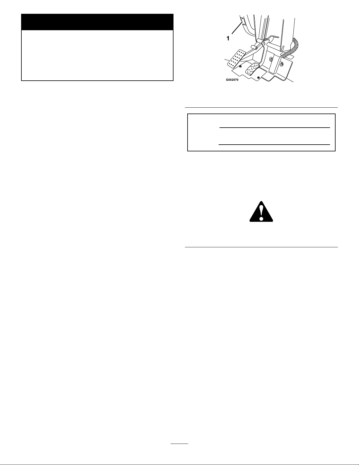
Figure1
1.Modelandserialnumberlocation
ModelNo.
SerialNo.
Thismanualidentiespotentialhazardsandhas
safetymessagesidentiedbythesafetyalertsymbol
(Figure2),whichsignalsahazardthatmaycauseserious
injuryordeathifyoudonotfollowtherecommended
precautions.
Figure2
1.Safetyalertsymbol
Thismanualuses2otherwordstohighlightinformation.
Importantcallsattentiontospecialmechanical
informationandNoteemphasizesgeneralinformation
worthyofspecialattention.
Wheneveryouneedservice,genuineToroparts,
oradditionalinformation,contactanAuthorized
ServiceDealerorToroCustomerServiceandhave
themodelandserialnumbersofyourproductready .
Figure1identiesthelocationofthemodelandserial
numbersontheproduct.Writethenumbersinthe
spaceprovided.
©2007—TheToro®Company
8111LyndaleAvenueSouth
Bloomington,MN55420
Contactusatwww.Toro.com.
2
PrintedintheUSA.
AllRightsReserved
Page 3

Contents
Introduction.................................................................2
Safety...........................................................................4
SafeOperatingPractices.......................................4
BeforeOperating.................................................4
Operation.............................................................5
Maintenance.........................................................7
SoundPressure.....................................................7
Vibration..............................................................7
SafetyandInstructionalDecals.............................8
Setup..........................................................................10
1InstallingtheWheels........................................10
2InstallingtheSteeringWheel............................11
3InstallingtheBumper.......................................11
4InstallingtheSeats...........................................11
5InstallingtheHitch..........................................12
6InstallingtheCargoBox...................................12
7ActivatingtheBattery......................................13
8AdjustingtheFrontWheelToe-in.....................14
9ReadingtheManualandViewingtheSafety
Video.............................................................14
ProductOverview......................................................16
Controls.............................................................16
Specications.....................................................19
Attachments/Accessories...................................19
Operation...................................................................19
ThinkSafetyFirst...............................................19
Pre-StartingChecks............................................19
CheckingtheEngineOil.....................................19
CheckingtheBrakeFluidLevel...........................20
CheckingtheTirePressure.................................20
AddingFuel.......................................................20
CheckingtheTransmissionOilLevel..................21
StartingtheEngine.............................................21
StoppingtheVehicle...........................................21
ParkingtheV ehicle.............................................21
OperatingtheCargoBox....................................22
BreakinginaNewVehicle..................................23
LoadingtheCargoBox.......................................23
TransportingtheVehicle.....................................23
TowingtheVehicle.............................................23
TowingaTrailer..................................................24
Maintenance...............................................................25
RecommendedMaintenanceSchedule(s)................25
DailyMaintenanceChecklist...............................25
PremaintenanceProcedures....................................27
MaintainingtheVehicleunderSpecial
OperatingConditions.....................................27
JackingtheVehicle..............................................27
Lubrication.............................................................28
AddingGrease...................................................28
EngineMaintenance...............................................28
ServicingtheAirCleaner....................................28
ServicingtheEngineOil.....................................29
ServicingtheSparkPlugs....................................30
FuelSystemMaintenance.......................................31
InspectingFuelLinesandConnections...............31
ReplacingtheFuelFilter.....................................31
ElectricalSystemMaintenance................................31
ReplacingtheFuses............................................31
ReplacingtheHeadlights....................................31
ServicingtheBattery...........................................32
DriveSystemMaintenance.....................................34
CheckingandAdjustingNeutral.........................34
InspectingtheTires............................................34
AdjustingtheFrontSuspension..........................34
AdjustingFrontWheelToe-In............................35
MaintainingthePrimaryDriveClutch.................36
ChangingtheTransaxleFluid..............................37
CoolingSystemMaintenance..................................38
CleaningtheEngineCoolingAreas.....................38
BrakeMaintenance.................................................38
InspectingtheBrakes.........................................38
CheckingtheBrakeFluidLevel...........................38
AdjustingtheParkingBrake................................38
BeltMaintenance....................................................39
ServicingtheDriveBelt......................................39
AdjustingtheStarterGeneratorBelt...................39
Cleaning.................................................................40
WashingtheV ehicle............................................40
Storage.......................................................................41
Schematics.................................................................42
3
Page 4
Safety
Improperuseormaintenancebytheoperatororowner
canresultininjury.Toreducethepotentialforinjury,
complywiththesesafetyinstructionsandalwayspay
attentiontothesafetyalertsymbol,whichmeans
Caution,Warning,orDanger—“personalsafety
instruction.”Failuretocomplywiththeinstructionmay
resultinpersonalinjuryordeath.
Supervisors,operators,andservicepersonsshouldbe
familiarwiththefollowingstandardsandpublications
(thematerialmaybeobtainedfromtheaddressshown):
•FlammableandCombustibleLiquidsCode:
ANSI/NFPA30
•NationalFireProtectionAssociation:
ANSI/NFPA#505;PoweredIndustrialTrucks,
NationalFirePreventionAssociation,Barrymarch
Park,Quincy ,Massachusetts02269U.S.A.
•ANSI/ASMEB56.8PersonalBurdenCarriers
AmericanNationalStandardsInstitute,Inc.,1430
Broadway,NewYork,NewYork10018U.S.A.
•SAEJ2258LightUtilityVehicle
SAEInternational,400CommonwealthDrive,
Warrendale,PA15096-0001U .S.A.
•ANSI/UL558;InternalCombustionEngine
PoweredIndustrialTrucks
AmericanNationalStandardsInstitute,Inc.,1430
Broadway,NewYork,NewYork10018U.S.A.
or
UnderwritersLaboratories,333PngstenRoad,
Northbrook,Illinois60062U .S.A.
BeforeOperating
•Operatethemachineonlyafterreadingand
understandingthecontentsofthismanual.
•Neverallowchildrentooperatethevehicle.Anyone
whooperatesthevehicleshouldhaveamotor
vehiclelicense.
•Neverallowotheradultstooperatethevehicle
withoutrstreadingandunderstandingtheOperator’ s
Manual.Onlytrainedandauthorizedpersonsshould
operatethisvehicle.Makesurethatalloperators
arephysicallyandmentallycapableofoperatingthe
vehicle.
•Thisvehicleisdesignedtocarryonlyyou,the
operator,andonepassengerintheseatprovidedby
themanufacturer.Nevercarryanyotherpassengers
onthevehicle.
•Neveroperatethevehiclewhenundertheinuence
ofdrugsoralcohol.Evenprescriptiondrugsand
coldmedicinescancausedrowsiness.
•Donotdrivethevehiclewhenyouaretired.Besure
totakeoccasionalbreaks.Itisveryimportantthat
youstayalertatalltimes.
•Becomefamiliarwiththecontrolsandknowhowto
stoptheenginequickly.
•Keepallshields,safetydevices,anddecalsinplace.
Ifashield,safetydevice,ordecalismalfunctioning,
illegible,ordamaged,repairorreplaceitbefore
operatingthemachine.
•Alwayswearsubstantialshoes.Donotoperate
themachinewhilewearingsandals,tennisshoes
orsneakers.Donotwearloosettingclothingor
jewelrywhichcouldgetcaughtinmovingpartsand
causepersonalinjury.
SafeOperatingPractices
TheWorkmanisanoff-highwayvehicleonly
andisnotdesigned,equipped,ormanufactured
foruseonpublicstreets,roads,orhighways.
Supervisor’sResponsibilities
•Makesurethatoperatorsarethoroughlytrainedand
familiarwiththeOperator’sManualandalllabelson
thevehicle.
•Besuretoestablishyourownspecialproceduresand
workrulesforunusualoperatingconditions(e.g.
slopestoosteepforvehicleoperation).
•Wearingsafetyglasses,safetyshoes,longpantsanda
helmetisadvisableandrequiredbysomelocalsafety
andinsuranceregulations.
•Avoiddrivingwhenitisdark,especiallyinunfamiliar
areas.Ifyoumustdrivewhenitisdark,besure
todrivecautiously,usetheheadlights,andeven
consideraddingadditionallights.
•Beextremelycarefulwhenoperatingaroundpeople.
Alwaysbeawareofwherebystandersmightbe.
•Beforeoperatingthevehicle,alwayscheckthe
designatedareasofthevehiclethatarestatedinthe
pre-startingsectionofthismanual.Ifsomething
iswrong,donotusethevehicle.Makesurethat
theproblemiscorrectedbeforethevehicleor
attachmentisoperated.
•Sincegasolineishighlyammable,handleitcarefully.
4
Page 5
–Useanapprovedgasolinecontainer.
–Donotremovethecapfromthefueltankwhen
theengineishotorrunning.
–Donotsmokewhilehandlinggasoline.
–Fillthefueltankoutdoors,andllittoabout
1inch(25mm)belowthetopofthetank(the
bottomofthellerneck).Donotoverllit.
–Wipeupanyspilledgasoline.
Operation
Engineexhaustcontainscarbonmonoxide,
whichisanodorless,deadlypoisonthatcan
killyou.
Donotrunengineindoorsorinanenclosed
area.
•Theoperatorandpassengershouldremainseated
wheneverthevehicleisinmotion.Theoperator
shouldkeepbothhandsonthesteeringwheel
wheneverpossible,andthepassengershoulduse
thehandholdsprovided.Keepyourarmsandlegs
withinthevehiclebodyatalltimes.
•Driveslowerandturnlesssharplywhenyouare
carryingapassenger.Rememberyourpassengermay
notbeexpectingyoutobrakeorturnandmaynot
beready .
•Alwayswatchoutforandavoidlowoverhangssuch
astreelimbs,doorjambs,andover-headwalkways.
Makesurethereisenoughroomoverheadtoeasily
clearthevehicleandyourhead.
•Failuretooperatethevehiclesafelymayresultinan
accident,tipoverofthevehicle,andseriousinjury
ordeath.Drivecarefully .Topreventtippingorloss
ofcontrol:
–Useextremecaution,reducespeed,andmaintain
asafedistancearoundsandtraps,ditches,creeks,
ramps,unfamiliarareas,oranyareasthathave
abruptchangesingroundconditionsorelevation.
–Watchforholesorotherhiddenhazards.
–Useextracautionwhenoperatingthevehicleon
wetsurfaces,inadverseweatherconditions,at
higherspeeds,orwithafullload.Stoppingtime
anddistancewillincreasewithafullload.
–Avoidsuddenstopsandstarts.Donotgofrom
reversetoforwardorforwardtoreversewithout
rstcomingtoacompletestop.
–Slowdownbeforeturning.Donotattempt
sharpturnsorabruptmaneuversorotherunsafe
drivingactionsthatmaycausealossofvehicle
control.
–Whendumping,donotletanyonestandbehind
thevehicleanddonotdumptheloadonanyone’s
feet.Releasethetailgatelatchesfromthesideof
thebox,notfrombehind.
–Onlyoperatethevehiclewhenthecargoboxis
downandlatched.
–Beforebackingup,looktotherearandensure
thatnooneisbehindyou.Backupslowly.
–Watchoutfortrafcwhenyouarenearor
crossingroads.Alwaysyieldtherightofway
topedestriansandothervehicles.Thisvehicle
isnotdesignedforuseonstreetsorhighways.
Alwayssignalyourturnsorstopearlyenough
sothatotherpeopleknowwhatyouplantodo.
Obeyalltrafcrulesandregulations.
–Theelectricalandexhaustsystemsofthevehicle
canproducesparkscapableofignitingexplosive
materials.Neveroperatethevehicleinornearan
areawherethereisdustorfumesintheairwhich
areexplosive.
–Ifyouareeverunsureaboutsafeoperation,stop
workandaskyoursupervisor.
•Donottouchtheengineormuferwhiletheengine
isrunningorsoonafterithasstopped.Theseareas
maybehotenoughtocauseburns.
•Ifthemachineevervibratesabnormally,stop
immediately,waitforallmotiontostop,andinspect
thevehiclefordamage.Repairalldamagebefore
commencingoperation.
•Beforegettingoffoftheseat:
1.Stopthemovementofthemachine.
2.Settheparkingbrake.
3.TurntheignitionkeytoOff.
4.Removetheignitionkey.
Note:Ifthevehicleisonanincline,blockthe
wheelsaftergettingoffofthevehicle.
Braking
•Slowdownbeforeyouapproachanobstacle.This
givesyouextratimetostoporturnaway.Hitting
anobstaclecandamagethevehicleanditscontents.
Moreimportant,itcaninjureyouandyourpassenger.
•GrossVehicleWeight(GVW)hasamajorimpacton
yourabilitytostopand/orturn.Heavyloadsand
attachmentsmakeavehiclehardertostoporturn.
Theheaviertheload,thelongerittakestostop.
5
Page 6

•Decreasethevehiclespeedifthecargoboxhasbeen
removedandthereisnoattachmentonthevehicle.
Thebrakingcharacteristicschangeandfaststops
maycausetherearwheelstolockup,whichmay
affectthecontrolofthevehicle.
•Turfandpavementaremuchmoreslipperywhen
theyarewet.Itcantake2to4timesaslongtostop
onwetsurfacesasondrysurfaces.Ifyoudrive
throughstandingwaterdeepenoughtogetthe
brakeswet,theywillnotworkwelluntiltheyare
dry.Afterdrivingthroughwater,youshouldtestthe
brakestomakesuretheyworkproperly .Iftheydo
not,driveslowlywhileputtinglightpressureonthe
brakepedal.Thiswilldrythebrakesout.
topreventitfromshiftingandtakeextracarewhen
haulingloadsthatshifteasily(liquid,rock,sand,etc.).
•Avoidstoppingonhills,especiallywithaload.
Stoppingwhilegoingdownahillwilltakelonger
thanstoppingonlevelground.Ifthevehiclemust
bestopped,avoidsuddenspeedchanges,whichmay
initiatetippingorrollingofthevehicle.Donotslam
onthebrakeswhenrollingbackward,asthismay
causethevehicletooverturn.
•Westronglyrecommendinstallingtheoptional
ROPSKitwhenoperatingonhillyterrain.
OperatingonRoughTerrain
OperatingonHills
Operatingthevehicleonahillmaycause
tippingorrollingofthevehicle,ortheengine
maystallandyoucouldloseheadwayonthe
hill.Thiscouldresultinpersonalinjury.
•Donotacceleratequicklyorslamonthe
brakeswhenbackingdownahill,especially
withaload.
•Iftheenginestallsoryouloseheadwayon
ahill,slowlybackstraightdownthehill.
Neverattempttoturnthevehiclearound.
•Operatethevehicleslowlyonahillanduse
caution.
•Avoidturningonahill.
•Reduceyourloadandthespeedofthe
vehicle.
•Avoidstoppingonhills,especiallywitha
load.
Theseextracautionsneedtobetakenwhenoperating
thevehicleonahill:
•Slowdownbeforestartingupordownahill.
•Iftheenginestallsoryoubegintoloseheadway
whileclimbingahill,graduallyapplythebrakesand
slowlybackstraightdownthehill.
•Turningwhiletravelingupordownhillscanbe
dangerous.Ifyouhavetoturnwhileonahill,do
itslowlyandcautiously.Nevermakesharporfast
turns.
•Heavyloadsaffectstability.Reducetheweightofthe
loadandyourspeedwhenoperatingonhillsorif
theloadhasahighcenterofgravity.Securetheload
Reducespeedandloadwhenoperatingonroughterrain,
unevenground,andnearcurbs,holes,andothersudden
changesinterrain.Loadsmayshift,causingthevehicle
tobecomeunstable.
WestronglyrecommendinstallingtheoptionalROPS
Kitwhenoperatingonroughterrain.
Suddenchangesinterrainmaycauseabrupt
steeringwheelmovement,possiblyresultingin
handandarminjuries.
•Reduceyourspeedwhenoperatingonrough
terrainandnearcurbs.
•Gripthesteeringwheellooselyaroundthe
perimeter.Keepyourhandsclearofthe
steeringwheelspokes.
LoadingandDumping
Theweightandpositionofthecargoandpassenger
canchangethevehiclecenterofgravityandvehicle
handling.T oavoidlossofcontrolandpersonalinjury,
followtheseguidelines:
•Donotcarryloadswhichexceedtheloadlimits
describedonthevehicleweightlabel;referto
SpecicationsinProductOverview,page16,for
vehicleweightlimits.Theloadratingisforlevel
surfacesonly .
•Reducetheweightoftheloadwhenoperating
onhillsandroughterraintoavoidtippingor
overturningofthevehicle.
•Reducetheweightoftheloadifthecenterofgravity
ishigh.Itemssuchasbricks,fertilizer,orlandscape
timbersstackhigherinthebox.Thehigheraload
isstacked,themorelikelythevehicleistotipover.
6
Page 7
Distributetheloadaslowaspossible,makingsure
thattheloaddoesnotaffectrearvisibility.
•Positiontheweightoftheloadevenlyfromsideto
side.Ifyoupositiontheloadtowardoneofthesides,
thevehicleismorelikelytotipoverwhileturning.
•Positiontheweightofaloadevenlyfromfrontto
back.Ifyoupositiontheloadbehindtherearaxle,
itwillreducetheweightonthefrontwheels.This
mayresultinalossofsteeringcontrolorcausethe
vehicletotipoveronhillsorbumpyterrain.
•Useextracautioniftheloadexceedsthedimensions
oftheboxandwhenhandlingoff-centerloadsthat
cannotbecentered.Keeploadsbalancedandsecure
topreventthemfromshifting.
•Alwayssecureloadssothattheydonotshift.Ifa
loadisnotsecured,oryouaretransportingaliquidin
alargecontainersuchasasprayer,theloadcanshift.
Thisshiftinghappensmostoftenwhileturning,
goingupordownhills,suddenlychangingspeeds,or
whiledrivingoverroughsurfaces.Shiftingloadscan
causethevehicletotipover.
Maintenance
•Onlyqualiedandauthorizedpersonnelshallbe
permittedtomaintain,repair,adjust,orinspectthe
vehicle.
•Beforeservicingormakingadjustmentstothe
machine,stoptheengine,settheparkingbrake,
andremovethekeyfromtheignitiontoprevent
someonefromaccidentallystartingtheengine.
•Tomakesurethattheentiremachineisingood
condition,keepallnuts,bolts,andscrewsproperly
tightened.
•Toreducethepotentialforre,keeptheengine
areafreeofexcessivegrease,grass,leaves,and
accumulationofdirt.
•Neveruseanopenametocheckthelevelor
leakageoffuelorbatteryelectrolyte.
•Iftheenginemustberunningtoperforma
maintenanceadjustment,keepyourhands,feet,
clothing,andanypartsofyourbodyawayfromthe
engineandanymovingparts.Keepeveryoneaway.
Theweightoftheboxmaybeheavy.Handsor
otherbodypartscouldbecrushed.
–Keephandsandotherbodypartsclearwhen
loweringthebox.
–Donotdumpmaterialsonbystanders.
•Neverdumpaloadedcargoboxwhilethevehicleis
sidewaysonahill.Thechangeinweightdistribution
maycausethevehicletooverturn.
•Whenoperatingwithaheavyloadinthecargobox,
reduceyourspeedandallowforsufcientbraking
distance.Donotsuddenlyapplythebrakes.Use
extracautiononslopes.
•Beawarethatheavyloadsincreaseyourstopping
distanceandreduceyourabilitytoturnquickly
withouttippingover.
•Therearcargospaceisintendedforloadcarrying
purposesonly ,notforpassengers.
•Neveroverloadyourvehicle.Thedecal(locatedon
therearframe)showsloadlimitsforthevehicle.
NeveroverloadtheattachmentsorexceedtheGross
VehicleWeight(GVW).
•Donotuseopenpansoffuelorammablecleaning
uidsforcleaningparts.
•Ifmajorrepairsareeverneededorassistanceis
required,contactanAuthorizedToroDistributor.
•Tobesureofoptimumperformanceandsafety,
alwayspurchasegenuineTororeplacementpartsand
accessories.Replacementpartsandaccessoriesmade
byothermanufacturerscouldbedangerous.Altering
thisvehicleinanymannerthatmayaffectvehicle
operation,performance,durability,oritsuse,may
resultininjuryordeath.Suchusecouldvoidthe
productwarranty.
SoundPressure
Thisunithasamaximumsoundpressurelevelatthe
operator’searof80dBA,basedonmeasurementsof
identicalmachinesperEN11094.
Vibration
Thisunitdoesnotexceedahand/armvibrationlevelof
2.5m/s
perEN1033.
Thisunitdoesnotexceedawholebodyvibration
levelof0.5m/s
machinesperEN1032.
2
,basedonmeasurementsofidenticalmachines
2
,basedonmeasurementsofidentical
7
Page 8
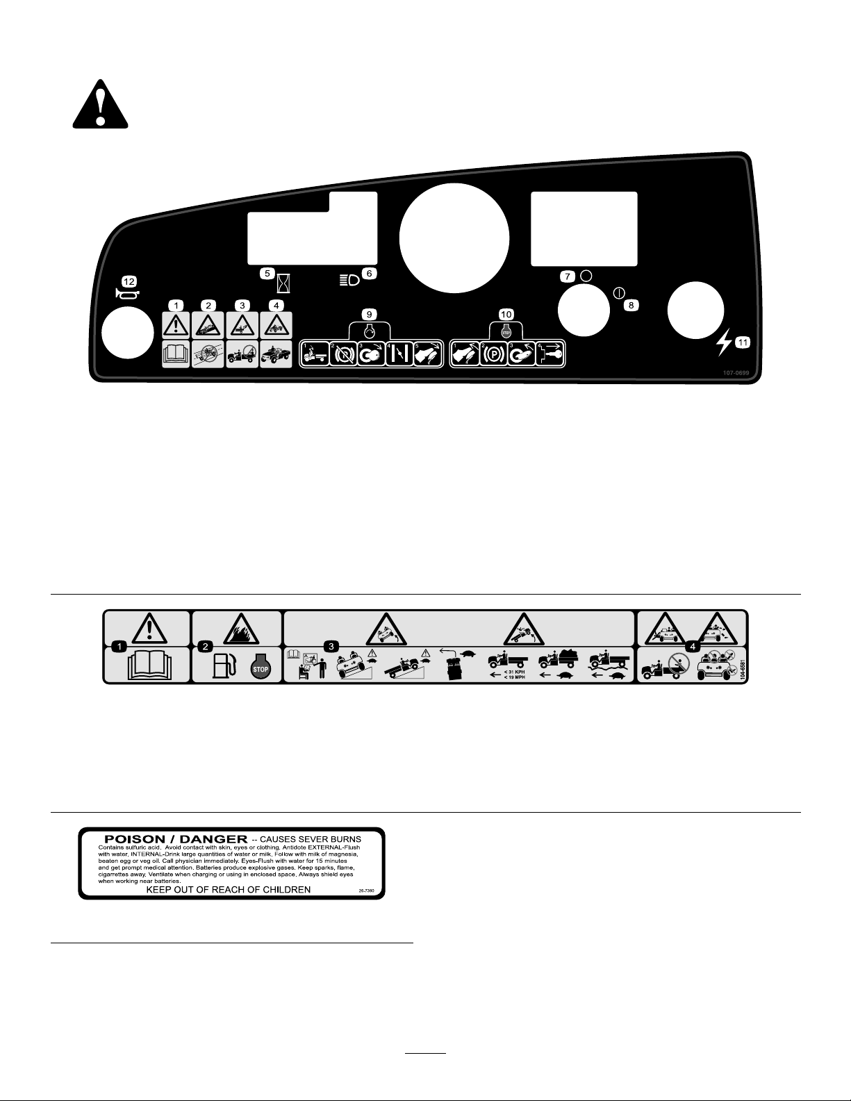
SafetyandInstructionalDecals
Safetydecalsandinstructionsareeasilyvisibletotheoperatorandarelocatednearanyareaof
potentialdanger.Replaceanydecalthatisdamagedorlost.
107-0699
1.Warning—readtheOperator’sManual.7.Ignition—Off
2.Collisionhazard—donotoperatethevehicleonpublicstreets,
roads,orhighways.
3.Fallinghazard—donotcarrypassengersinthecargobed.9.Tostarttheengine,sitontheoperator’sseat,releasethe
4.Fallinghazard—donotallowchildrentooperatethevehicle.10.Tostoptheengine,releasetheacceleratorpedal,setthe
5.Hourmeter
6.Headlights12.Horn
8.Ignition—On
parkingbrake,turntheignitionkeyon,pullthechokeleverout
(ifneeded),andpresstheacceleratorpedal.
parkingbrake,turntheignitionkeyoff,andremovethe
ignitionkey.
11.Electricalpower(powerpoint)
104-6581
1.Warning—readtheOperator’sManual.
2.Firehazard—beforefueling,stoptheengine.
3.Tippinghazard—receivetrainingbeforeoperatingthemachine,usecautionanddriveslowlywhileonslopes;driveslowlywhen
turning,keepthevehiclespeedunder19MPH(31km/h)whencarryingafullorheavyloadandwhendrivingonroughterrain.
4.Fallingandarm/leginjuryhazards—donotcarrypassengersinthecargobedandkeeparmsandlegsinsideofthevehicleatall
times.
26-7390
8
Page 9
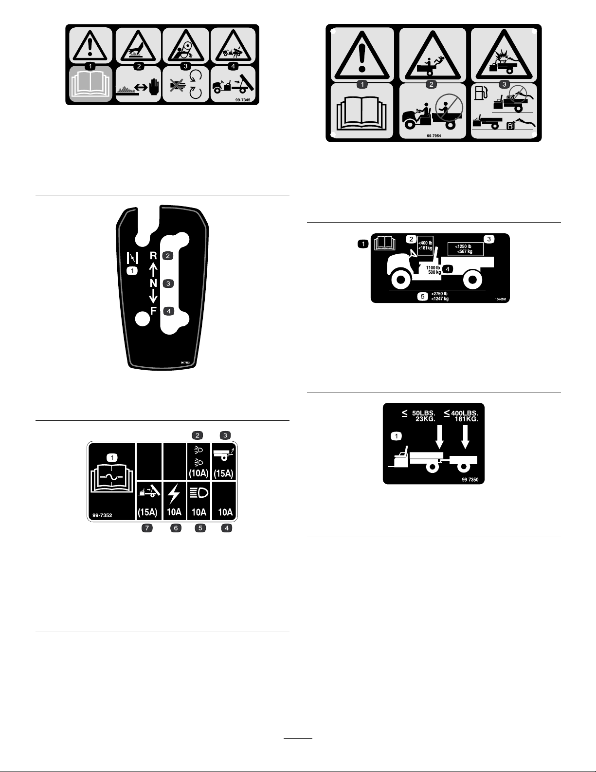
99-7345
1.Warning—readtheOperator’sManual.
2.Hotsurface/burnhazard—stayasafedistancefromthe
hotsurface.
3.Entanglementhazard,belt—stayawayfrommovingparts
4.Crushinghazard,cargobox—usetheproprodtosupport
thecargobed
99-7952
1.Choke
2.Reverse4.Forward
3.Neutral
99-7954
1.Warning—readtheOperator’sManual.
2.Fallinghazard—donotcarrypassengersinthecargobed.
3.Explosionhazard,staticdischargeintofuelcontainer—do
notllfuelcontainersinthecargobed;placefuelcontainers
onthegroundbeforelling.
104–6591
1.ReadtheOperator’sManual.
2.Themaximumcombinedoperatorandpassengerweightis
400lb.(181kg).
3.Themaximumcargoweightis1250lb.(567kg).
4.Thebaseweightofthevehicleis1 100lb.(500kg).
5.Themaximumgrossvehicleweightis2750lb.(1247kg).
99-7352
1.ReadtheOperator’sManualforinformationonfuses.
2.10amp.fusefortheoptionalRoadLightKit
3.15amp.fusefortheoptionalRearLiftKit
4.10amp.fuse—open
5.10amp.fusefortheheadlights
6.10amp.fusefortheignitionsystem
7.15amp.fusefortheoptionalElectricBedLiftKit
99-7350
1.Maximumtongueweightis50lb(23kg);maximumtrailer
weightis400lb(181kg).
9
Page 10

Setup
LooseParts
Usethechartbelowtoverifythatallpartshavebeenshipped.
ProcedureDescription
1
2
3
4
5
6
7
8
9
Wheelassembly4
Steeringwheel
Bumper1
Seat
Hitch1
Cargobox
Right-handpivotbracket1
Left-handpivotbracket
Flangeheadscrew(3/8x1inch)
Bolt(5/16x3/4inch)
Flangenut(5/16inch)
Nopartsrequired
Nopartsrequired
Operator’sManual
EngineOperator’sManual
PartsCatalog
SafetyVideo
RegistrationCard
PredeliveryInspectionForm1
Key2
Qty.
Use
Installthewheels(Model07277TC
only).
1
2
1
1
4
1
1
–
–
1
1
1
1
1
Installthesteeringwheel(Model
07277TConly).
Installthebumper(Model07277TC
only).
Installtheseats(Model07277TConly).
Installthehitch(Model07277TConly).
Installthecargobox(Model07277TC
only).
Activatethebattery(Model07277TC
only).
Adjustthefrontwheeltoe-in.
ReadtheOperator’sManualandwatch
thevideobeforeoperatingthemachine.
Note:Determinetheleftandrightsidesofthemachine
fromthenormaloperatingposition.
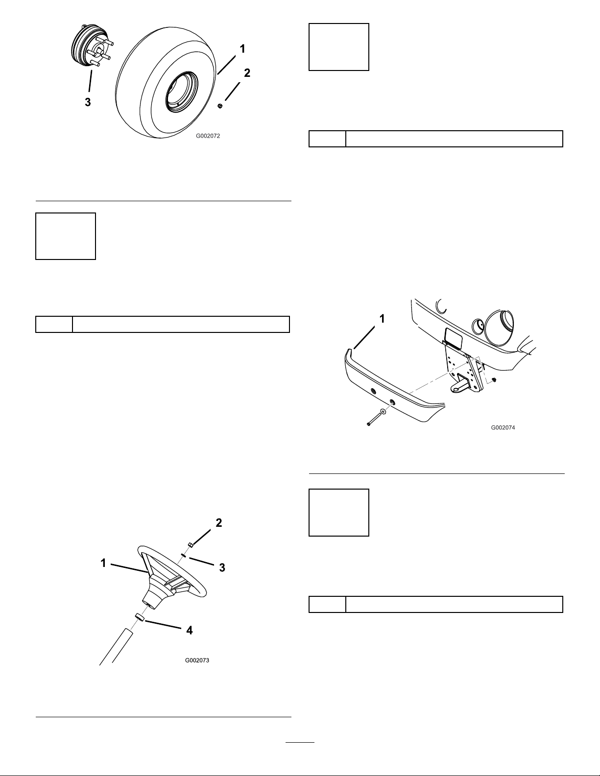
1
InstallingtheWheels
Partsneededforthisprocedure:
4Wheelassembly
Procedure
Note:ThisprocedureisonlyneededforModelNo.
07277TC.
1.Removethefastenerssecuringthewheels.
2.Removetheshippingbracketsecuredtothewheel
studs.
3.Mountthewheelswiththepreviouslyremoved
fasteners(Figure3)andtorqueto45-65ft-lb
(61-88N-m).
10
Page 11
3
InstallingtheBumper
Partsneededforthisprocedure:
Figure3
1.Wheelassembly
2.Wheelnut
3.Wheelstud(rearwheel
hubshown)
2
InstallingtheSteeringWheel
Partsneededforthisprocedure:
1
Steeringwheel
Procedure
Note:ThisprocedureisonlyneededforModelNo.
07277TC.
1.Removethenutandwasherfromthesteeringshaft.
2.Slidethesteeringwheelandwasherontotheshaft.
Positionthesteeringwheelontheshaftsothatthe
crossbeamishorizontalwhenthetiresarepointed
straightaheadandthethickerspokeofthesteering
wheelisdownward.
3.Securethesteeringwheeltotheshaftwiththenut
(Figure4).Torquethenutto18-22ft-lb(24-29N-m)
1Bumper
Procedure
Note:ThisprocedureisonlyneededforModelNo.
07277TC.
1.Removethe2bolts,washers,andnutssecuredtothe
frontoftheframe.
2.Alignthemountingholesandsecurethebumper
totheframewiththefastenerspreviouslyremoved
(Figure5).
Figure5
1.Bumper
Figure4
1.Steeringwheel
2.Nut4.Foamseal
3.Washer
4
InstallingtheSeats
Partsneededforthisprocedure:
2
Seat
Procedure
Note:ThisprocedureisonlyneededforModel
No.07277TC.
Inserttheseatbracketintotheseatbaseopeningand
pivottheseatdownward(Figure6).
11
Page 12
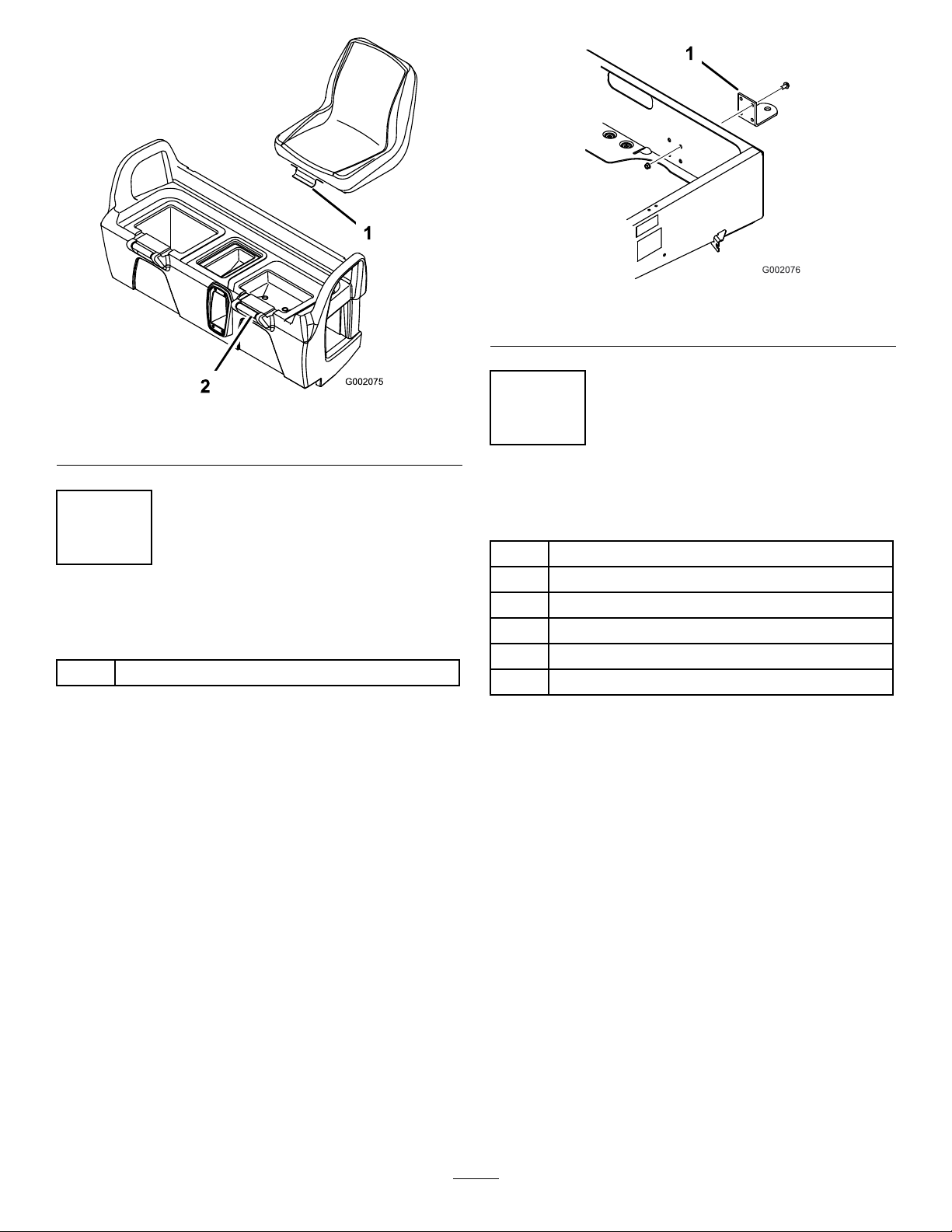
Figure6
1.Seatbracket2.Seatbase
Figure7
1.Hitch
6
InstallingtheCargoBox
Partsneededforthisprocedure:
5
InstallingtheHitch
Partsneededforthisprocedure:
1Hitch
Procedure
Note:ThisprocedureisonlyneededforModelNo.
07277TC.
1.Removethe4boltsandnutsfromtheinsiderear
oftheframe.
2.Alignthehitchwiththemountingholesonthe
frame.Securethehitchwiththescrewsandnuts
(Figure7).
1
Cargobox
1Right-handpivotbracket
1
Left-handpivotbracket
4
Flangeheadscrew(3/8x1inch)
1
Bolt(5/16x3/4inch)
1
Flangenut(5/16inch)
Procedure
Note:ThisprocedureisonlyneededforModel
No.07277TC.
1.Positionthecargoboxontotheframe.Thecargo
boxmustlayatandbecentered.
2.Mountthelefthandpivotbrackettotheleftrear
corneroftheframewith2angeheadscrews(3/8x
1inch).PositionthebracketasshowninFigure8.
12
Page 13
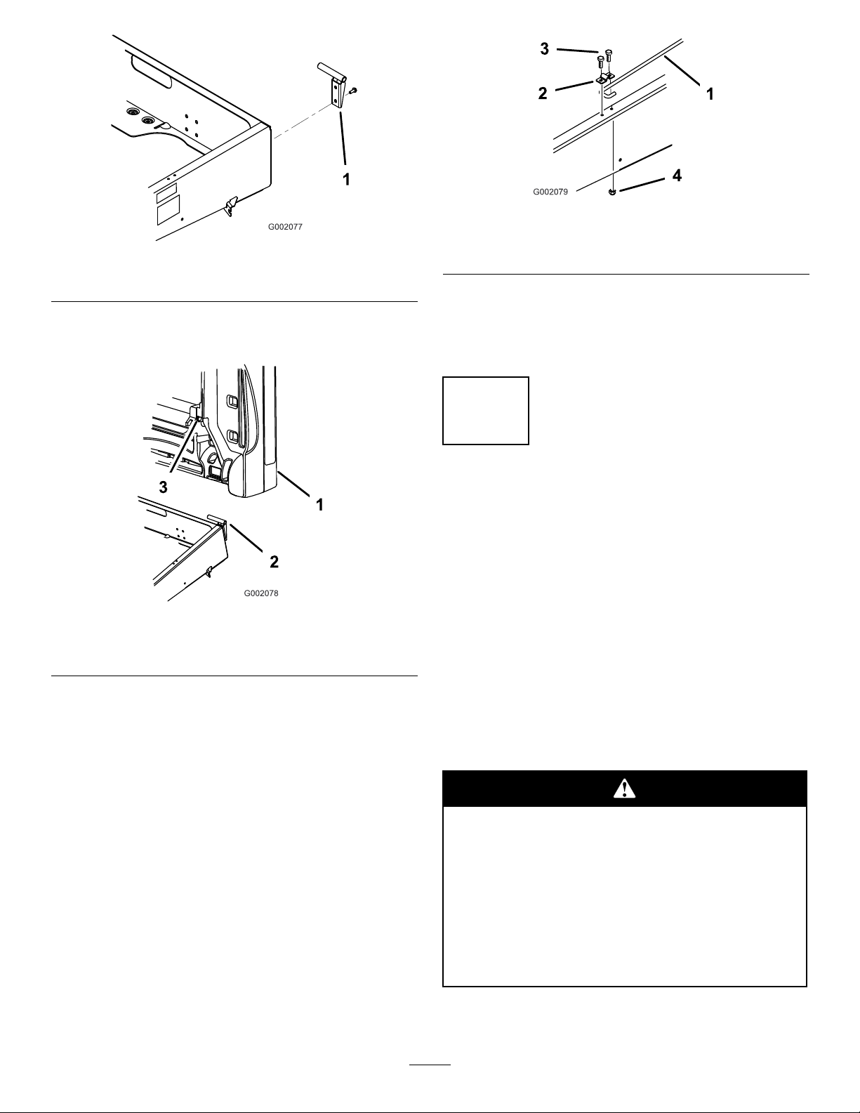
Figure8
1.Pivotbracket
3.Slidethecargoboxmountingholeontothepivot
bracket(Figure9).
Figure10
1.Proprod
2.Proprodclip
7.Tightentheboltandsecuretheothersideoftheclip
withanewbolt(5/16x3/4inch)andangenut
(5/16inch)(Figure10).
8.Lowerthecargobox.
3.Bolt(5/16x3/4inch)
4.Flangenut(5/16inch)
7
ActivatingtheBattery
NoPartsRequired
Procedure
None
Figure9
1.Cargobox3.Cargoboxmountinghole
2.Pivotbracket
4.Inserttherighthandpivotbracketintothemounting
holeinthecargoboxandthenmountittotheframe.
5.Haveanotherpersonhelptoraisethecargobox.
6.Loosentheboltsecuringtheproprodcliptothe
frameuntilyoucanslidetheJ-hookendoftheprop
rodundertheclip(Figure10).
Note:ThisprocedureisonlyneededforModelNo.
07277TC.
Ifthebatteryisnotlledwithelectrolyteoractivated,it
mustberemovedfromthevehicle,lledwithelectrolyte,
andcharged.Bulkelectrolytewith1.260specicgravity
mustbepurchasedfromalocalbatterysupplyoutlet.
1.Removethebatteryhold-downandliftthebattery
outofthebatterybase.
Batteryelectrolytecontainssulfuricacidwhich
isadeadlypoisonandcausessevereburns.
•Donotdrinkelectrolyteorallowittocontact
yourskin,eyesorclothing.Wearsafety
glassestoshieldyoureyesandrubbergloves
toprotectyourhands.
•Fillthebatterywherecleanwaterisalways
availableforushingtheskin.
2.Removethellercapsfromthebatteryandslowly
lleachcelluntilelectrolyteisjustabovetheplates.
13
Page 14

3.Replacethellercapsandconnecta3to4amp.
batterychargertothebatteryposts.Chargethe
batteryatarateof3to4amperesfor4to8hours
(12volts).Donotoverchargethebattery.
Chargingthebatteryproducesgassesthatcan
explode.
Neversmokenearthebatteryandkeepsparks
andamesawayfrombattery.
4.Whenthebatteryischarged,disconnectthecharger
fromtheelectricaloutletandbatteryposts.
5.Removethellercaps.Slowlyaddelectrolyteto
eachcelluntilelectrolyteisuptothellline.Install
thellercaps.
Important:Donotoverllthebattery.
Electrolytewilloverowontootherpartsofthe
vehicleandseverecorrosionanddeterioration
willresult.
Ifthevehiclewillberunwithmediumtoheavyloads
mostofthetime,setthetoe-inonthehighsideof
therecommendedamount.Ifitisgoingtoberun
withalightloadmostofthetime,setthetoe-inon
thelowsideoftherecommendedamount.
1.Measurethedistancebetweenbothofthefronttires
attheaxleheightatboththefrontandrearofthe
fronttires(Figure11).Axtureoralignmentgauge
isneededfortherearmeasurementofthefronttires
ataxleheight.Usethesamextureoralignment
gaugetoaccuratelymeasurethefrontofthefront
tiresataxleheight(Figure11).
6.Installthebattery;refertoInstallingtheBattery,
ElectricalSystemMaintenance,page31.
8
AdjustingtheFrontWheel
Toe-in
NoPartsRequired
Procedure
Thetoe-inshouldbe1/8-5/8inch(3-16mm)withthe
followingparameters:
•Thetirepressureshouldbeat12psi(83kPa).
•Therideheightshouldbecorrectbeforesettingthe
toe-in;refertotheAdjustingtheFrontSuspension
procedureinMaintenance,page25.
•Thevehicleshouldbedrivenbackandforthafew
timestorelaxtheA-arms.
•Measurethetoe-inwiththewheelsfacingstraight
aheadanda175-225lb(79-102kg)operatorinthe
driver’sseat.
Note:Thedrivershoulddriveuptothe
measurementareaandstayseatedinthevehicle
whilethemeasurementisbeingtaken.
Figure11
1.Tirecenterline-back4.Fixture
2.Tirecenterline-front
3.Axlecenterline
2.Ifthemeasurementdoesnotfallwithinthespecied
range(refertothedimensionsandparametersatthe
beginningofthisprocedure),loosenthejamnutsat
bothendsofthetierods(Figure12).
1.Jamnut2.Tierod
3.Rotatebothtierodstomovethefrontofthetire
inwardoroutward.
4.Tightenthetierodjamnutswhentheadjustmentis
correct.
5.Ensurethatthereisfulltravelofthesteeringwheel
inbothdirections.
5.Axlecenterlinedistance
6.6inches(15cm)ruler
Figure12
14
Page 15

9
ReadingtheManualand
ViewingtheSafetyVideo
Partsneededforthisprocedure:
1
Operator’sManual
1
EngineOperator’sManual
1
PartsCatalog
1
SafetyVideo
1
RegistrationCard
1PredeliveryInspectionForm
2Key
Procedure
•ReadtheOperator’ sManualandEngineOperator’s
Manual.
•Viewthesafetyvideo.
•Fillouttheregistrationcard.
•CompletethePredeliveryInspectionForm.
15
Page 16

ProductOverview
1.Steeringwheel
2.Gearshiftselector
Figure13
3.Parkingbrake
4.Fuelcap6.T owingtongue
5.Cargobox7.Cargoboxreleaselever
Controls
AcceleratorPedal
Theacceleratorpedal(Figure14)givestheoperatorthe
abilitytovarygroundspeedofthevehicle.Pressing
thepedalstartstheengine.Pressingthepedalfarther
increasesgroundspeed.Releasingthepedalwillslow
thevehicleandtheenginewillstoprunning.Maximum
forwardspeedis16mph(26km/h).
Figure14
1.Acceleratorpedal2.Brakepedal
BrakePedal
Thebrakepedalisusedtostoporslowthevehicle
(Figure14).
Brakescanbecomewornorcanbemisadjusted
resultinginpersonalinjury.
Ifbrakepedaltravelstowithin1inch(25mm)
ofthevehicleoorboard,thebrakesmustbe
adjustedorrepaired.
ParkingBrake
Theparkingbrakeisbetweentheseats(Figure15).
Whenevertheengineisshutoff,theparkingbrake
mustbeengagedtopreventaccidentalmovementof
thevehicle.T oengagetheparkingbrake,pullbackon
thelever.Todisengage,pushtheleverforward.Ifthe
vehicleisparkedonasteepgrade,makesurethatthe
parkingbrakeisapplied.Placeblocksatthedownhill
sideofthewheels.
16
Page 17

Figure15
1.Parkingbrakelever
ChokeControl
Thechokecontrolislocatedbelowandtotherightof
theoperator’sseat.Tostartacoldengine,pullthechoke
controloutward(Figure16).Aftertheenginestarts,
regulatethechoketokeeptheenginerunningsmoothly.
Assoonaspossible,pushthecontrolintotheOff
position.Awarmenginerequireslittleornochoking.
Figure16
1.Choke2.Gearshiftselector
Figure17
1.Ignitionswitch
2.Hourmeter5.PowerPoint
3.Lightswitch6.HornButton
4.Oillight
HourMeter
Thehourmeter(Figure17)indicatesthetotalnumber
ofhourstheenginehasrun.Thehourmeterstartsto
functionwhenevertheacceleratorispressed.
OilLight
Theoillightwarnstheoperatoriftheengineoillevel
dropsbelowasafelevel(Figure17).Ifthelightcomes
onandremainslit,theoillevelshouldbecheckedand
oiladdedifnecessary;refertoCheckingtheEngineOil
inOperation,page19.
Note:Theoillightmayicker.Thisisnormalandno
actionneedstobetaken.
GearShiftSelector
Thegearshiftselectorhasthreepositions:forward,
reverse,andneutral(Figure16).Theenginewillstart
andruninanyofthethreepositions.
Note:IfthegearshiftselectorisinReversewhenthe
ignitionisturnedon,abuzzerwillsoundtowarnthe
operator.
Important:Alwaysstopthevehiclebefore
changinggears.
IgnitionSwitch
Theignitionswitch(Figure17),usedtostartandstopthe
engine,hastwopositions:OffandOn.Rotatethekey
clockwisetotheOnpositiontoallowoperation.When
thevehicleisstopped,rotatethekeycounterclockwise
totheOffposition.Removethekeyfromtheignition.
LightSwitch
Toggletheswitchtoactivatetheheadlights.Pushto
turnthelightson(Figure17).
PowerPoint
Usethepowerpointtopower12voltoptionalelectrical
accessories(Figure17).
HornButton
Pressthehornbuttontosoundthehorn(Figure17).
FuelGauge
Thefuelgauge(Figure18)showstheamountoffuel
inthetank.
17
Page 18

Figure18
1.Fuelgauge
PassengerHandHolds
Thepassengerhandholdsarelocatedontherightsideof
thedashpanelandattheoutsideofeachseat(Figure19).
Figure19
1.Passengerhandhold2.Hiprestraint
18
Page 19

Specications
Note:Specicationsanddesignaresubjecttochangewithoutnotice.
Baseweight
Ratedcapacity(onlevelground)1650lb(749kg)total,including200lb(90.7kg)operatorand200lb(90.7kg)passenger ,load,
Maximumgrossvehicleweight
(GVW)(onlevelground)
Maximumcargocapacity(onlevel
ground)
Towcapacity:
StandardHitchTongueweight50lb(23kg)Maximumtrailerweight400lb(182kg)
HeavyDutyHitch
Overallwidth59inches(150cm)
Overalllength115inches(292cm)
Groundclearance9-1/4inches(23.5cm)atthefrontwithnoloadoroperator,7inches(18cm)attherearwith
Wheelbase
Wheeltread(centerlinetocenter
line)
Cargoboxlength46inches(1 16.8cm)inside,51inches(129.5cm)outside
Cargoboxwidth49inches(124.5cm)inside,54inches(137.2cm)outside
Cargoboxheight10inches(25.4cm)inside
Dry1050lb(476kg)
trailertongueweight,grosstrailerweight,accessories,andattachments
2700lb(1225kg)total,includingalloftheweightslistedabove
1250lb(567kg)total,includingtrailertongueweightandgrosstrailerweight
Tongueweight100lb(45kg)Maximumtrailerweight800lb(363kg)
noloadoroperator
79inches(200.7cm)
49inches(124.5cm)inthefront,48-1/4inches(122.6cm)intherear
Attachments/Accessories
AselectionofToroapprovedattachmentsandaccessoriesareavailableforusewiththemachinetoenhanceand
expanditscapabilities.ContactyourAuthorizedServiceDealerorDistributororgotowww .Toro.comforalistof
allapprovedattachmentsandaccessories.
Operation
Note:Determinetheleftandrightsidesofthemachine
fromthenormaloperatingposition.
ThinkSafetyFirst
Pleasecarefullyreadallofthesafetyinstructionsand
decalsinthesafetysection.Knowingthisinformation
couldhelpyouorbystandersavoidinjury.
Pre-StartingChecks
Checkthefollowingitemseachtimeyoubeginusingthe
vehiclefortheday:
•Checkthetirepressure.
Note:Thesetiresaredifferentthancartires;they
requirelesspressuretominimizeturfcompaction
anddamage.
•Checkalluidlevelsandaddtheappropriateamount
ofspecieduids,ifanyarefoundtobelow .
•Checkthebrakepedaloperation.
•Ensurethatthelightsareworking.
•Turnthesteeringwheeltotheleftandrighttocheck
steeringresponse.
•Checkforoilleaks,looseparts,andanyother
noticeablemalfunctions.Makesuretheengineisoff
andallmovingpartshavestoppedbeforechecking
foroilleaks,looseparts,andothermalfunctions.
Ifanyoftheaboveitemsarenotcorrect,notify
yourmechanicorcheckwithyoursupervisorbefore
takingthevehicleoutfortheday.Yoursupervisor
maywantyoutocheckotheritemsonadailybasis,
soaskwhatyourresponsibilitiesare.
CheckingtheEngineOil
Note:Theengineisshippedwithoilinthecrankcase;
however,theleveloftheoilmustbecheckedbeforeand
aftertheengineisrststarted.
19
Page 20

Checktheengineoillevelbeforestartingtheengine
eachday.
1.Positionthemachineonalevelsurface.
2.Cleanaroundtheoildipstick(Figure20)sodirt
cannotfallintotheholeanddamagetheengine.
Figure20
1.Oildipstick
3.Removetheoildipstickandwipetheendclean.
4.Slidetheoildipstickintothellertubefullyseating
it.Pullthedipstickoutandlookattheend.
AddingFuel
Usefresh,clean,unleadedregulargasolinesuitablefor
automotiveuse(87pumpoctaneminimum).Leaded
gasolinemaybeusedifunleadedregularisnotavailable.
Important:Neverusegasolinecontaining
methanol,gasolinecontainingmorethan10%
ethanol,gasolineadditives,orwhitegasbecause
enginefuelsystemdamagecouldresult.
Incertainconditions,gasolineisextremely
ammableandhighlyexplosive.Areor
explosionfromgasolinecanburnyouand
othersandcandamageproperty.
•Fillthefueltankoutdoors,inanopenarea,
whentheengineiscold.Wipeupany
gasolinethatspills.
•Neverllthefueltankinsideanenclosed
trailer.
Iftheoillevelislow ,removethellercapandaddoil
ofthepropertypetoraisethelevelto,butnotover,
theFullmarkonthedipstick.RefertoServicingthe
EngineOilinEngineMaintenance,page28,forthe
properoiltypeandviscosity.Addtheoilslowlyand
checktheleveloftenduringthisprocess.Donot
overll.
5.Installtheoildipstickrmlyinplace.
CheckingtheBrakeFluid
Level
Checkthebrakeuidlevelbeforetheengineisrst
started;refertoCheckingtheBrakeFluidLevelinBrake
Maintenance,page38.
CheckingtheTirePressure
Checkthetirepressureevery8hoursordailytoensure
properlevels.
Theairpressurerangeinthefrontandreartiresis
8–22psi(55–103kPa).
•Donotllthefueltankcompletelyfull.Add
gasolinetothefueltankuntilthelevelis1/4
to1/2inch(6to13mm)belowthebottomof
thellerneck.Thisemptyspaceinthetank
allowsgasolinetoexpand.
•Neversmokewhenhandlinggasoline,and
stayawayfromanopenameorwhere
gasolinefumesmaybeignitedbyaspark.
•Storegasolineinanapprovedcontainerand
keepitoutofthereachofchildren.Never
buymorethana30-daysupplyofgasoline.
•Donotoperatewithoutentireexhaust
systeminplaceandinproperworking
condition.
Theairpressureneededisdeterminedbythepayload
carried.Thelowertheairpressure,thelessthe
compaction,smoothertheride,andtiremarksare
minimized.Lowerpressureshouldnotbeusedfor
heavypayloadsathighspeeds.
Higherpressuresshouldbeusedforheavierpayloadsat
higherspeeds.Donotexceedthemaximumpressure.
20
Page 21

CheckingtheTransmissionOil
Incertainconditionsduringfueling,static
electricitycanbereleasedcausingaspark
whichcanignitethegasolinevapors.Are
orexplosionfromgasolinecanburnyouand
othersandcandamageproperty.
•Alwaysplacegasolinecontainersonthe
groundawayfromyourvehiclebeforelling.
•Donotllgasolinecontainersinsidea
vehicleoronatruckortrailerbedbecause
interiorcarpetsorplastictruckbedliners
mayinsulatethecontainerandslowtheloss
ofanystaticcharge.
•Whenpractical,removegas-powered
equipmentfromthetruckortrailerand
refueltheequipmentwithitswheelsonthe
ground.
•Ifthisisnotpossible,thenrefuelsuch
equipmentonatruckortrailerfroma
portablecontainer,ratherthanfroma
gasolinedispensernozzle.
•Ifagasolinedispensernozzlemustbeused,
keepthenozzleincontactwiththerimof
thefueltankorcontaineropeningatall
timesuntilfuelingiscomplete.
Level
Thetransaxleuidlevelshouldbeatthebottomof
thelevelindicatorhole(Figure22).Ifitisnot,llthe
reservoirwiththeappropriateuid;refertoChanging
theTransaxleFluidinDriveSystemMaintenance,
page34.
Figure22
1.Levelindicatorhole
StartingtheEngine
1.Sitintheoperator’sseat,insertthekeyintothe
ignitionswitch,androtatethekeyclockwisetothe
Onposition.
Note:IfthegearshiftselectorisinReverse,the
buzzerwillsoundtowarntheoperator.
2.Movethegearshiftselectortothedesiredposition.
FillingtheFuelTank
Thefueltankcapacityisapproximately7gallons(26.5l).
1.Shuttheengineoffandsettheparkingbrake.
2.Cleantheareaaroundthefueltankcap(Figure21).
Figure21
1.Fueltankcap
3.Removethefueltankcap.
4.Fillthetanktoabout1inch(25mm)belowthetop
oftank,(bottomofthellerneck).Thisspaceinthe
tankallowsgasolinetoexpand.Donotoverll.
5.Installthefueltankcapsecurely .Wipeupanyfuel
thatmayhavespilled.
3.Releasetheparkingbrake.
4.Slowlystepontheacceleratorpedal.
Note:Iftheengineiscold,pressandholdthe
acceleratorpedalabouthalf-waydown,andpullthe
chokeknobouttotheOnposition.Returnthe
chokeknobtoOffaftertheenginewarmsup.
Important:Donotattempttopushortowthe
vehicletogetitstarted.
StoppingtheVehicle
Tostopthevehicle,removeyourfootfromthe
acceleratorpedalandslowlypressthebrakepedal.
Note:Stoppingdistancemayvarydependingonthe
vehicleloadandspeed.
ParkingtheVehicle
1.Engagetheparkingbrakeandrotatetheignition
keytoOff.
2.Removethekeyfromtheignitionswitchtoprevent
accidentalstarting.
21
Page 22

OperatingtheCargoBox
RaisingtheBox
LoweringtheBox
Theweightoftheboxmaybeheavy.Handsor
otherbodypartscouldbecrushed.
Drivingthevehiclewiththecargoboxraised
maycausethevehicletotiporrolleasier.The
boxstructuremaybecomedamagedifyou
operatethevehiclewiththeboxraised.
•Onlyoperatethevehiclewhenthecargobox
isdown.
•Afterdumpingaload,lowerthecargobox.
1.Lifttheleveroneithersideoftheboxandliftthe
boxup(Figure23).
Figure23
1.Lever
Keephandsandotherbodypartsclearwhen
loweringthebox.
Pulltheproprodoutofthedetentslotandlowerthe
boxuntilitlatchesintoplace.
AdjustingtheBoxLatches
Iftheboxlatchdoesnotlatchtightly,vibratingupand
downasyoudrivethevehicle,youcanadjustthelatch
poststomakethelatchestsnugly.
1.Loosenthenutontheendofthelatchpost
(Figure25).
2.Pulltheproprodintothedetentslot,securingthe
box(Figure24).
Figure24
1.Proprod
Figure25
1.Latch3.Latchpost
2.Nut
2.Turnthelatchpostclockwiseuntilitissnugagainst
thelatchandthentightenthenut(Figure25).
3.Repeatthisprocedureforthelatchontheotherside
ofthevehicle.
OperatingtheTailgateLatches
1.Toopenthetailgatelatches,liftthelatchhandlesup
(Figure26).Thelatcheswillspringouttowardthe
centerofthetailgate.Slowlylowerthetailgate.
Note:Youmayneedtopushtheendofthetailgate
in(especiallyifthereisaloadagainstthetailgate)
beforethelatcheswillspringtowardthecenterof
thetailgateandrelease.
22
Page 23

Seethetablebelowforloadvolumelimitswithvarious
materials:
Figure26
1.Tailgatelatch
2.Toclosethetailgatelatches,liftthehandlesupward
andslidethemtowardtheoutsideofthevehicle.
3.Pushthelatchhandlesdownwardtosecurethelatch
andtailgate.
BreakinginaNewVehicle
Toprovideproperperformanceandlongvehiclelife,
followtheseguidelinesfortherst100operatinghours:
•Checktheuidandengineoillevelsregularlyandbe
alertforindicationsofoverheatinginanycomponent
ofthevehicle.
•Afterstartingacoldengine,letitwarmupforabout
15secondsbeforeaccelerating.
•Avoidhardbrakingsituationsfortherstseveral
hoursofnewvehiclebreak-inoperation.Newbrake
liningsmaynotbeatoptimumperformanceuntil
severalhoursofusehascausedthebrakestobecome
burnished(broken-in).
MaterialMax.cargoboxcapacity
Gravel,dry3/4full(approx.)
Gravel,wet1/2full(approx.)
Sand,dry3/4full
Sand,wet1/2full
WoodFull
BarkFull
Earth,packed
(onlevelground)
3/4full(approx.)
TransportingtheVehicle
Formovingthevehiclelongdistances,atrailershould
beused.Makesurethatthevehicleissecuredtothe
trailer.RefertoFigure27andFigure28forthelocation
ofthetie-downpoints.
Looseseatsmayfalloffofthevehicleandtrailer
whentransportingandlandonanothervehicle
orbecomeanobstructionontheroad.
Removetheseatsormakesurethattheseats
aresecurelyfastenedinthedetents.
•Varythevehiclespeedduringoperation.Avoidfast
startsandquickstops.
•Abreak-inoilforengineisnotrequired.Original
engineoilisthesametypespeciedforregularoil
changes.
•RefertotheMaintenancesectionforanyspeciallow
hourchecks.
•Checkthefrontsuspensionpositioningandadjustit
ifnecessary;refertoAdjustingtheFrontSuspension
inDriveSystemMaintenance,page34.
LoadingtheCargoBox
Thecapacityofthecargoboxis13ft
3
(0.37m
amount(volume)ofmaterialthatcanbeplacedinthe
boxwithoutexceedingthevehicleloadratingscanvary
greatlydependingonthedensityofthematerial.For
example,alevelboxofwetsandweighs1500lb(680kg),
whichexceedstheloadratingby250lb(113kg).But
alevelboxofwoodweighs650lb(295kg),whichis
undertheloadrating.
3
).The
Figure27
1.Tiedownpoints
TowingtheVehicle
Incaseofanemergency,thevehiclecanbetowedfora
shortdistance.However,wedonotrecommendthisas
astandardprocedure.
23
Page 24

weight=50lb(23kg),thenthemaximumcargoload=
800lb(363kg)
Towingatexcessivespeedscouldcausealoss
ofsteeringcontrol,resultinginpersonalinjury.
Nevertowthevehiclefasterthan5mph
(8km/h).
Towingthevehicleisatwopersonjob.Ifthemachine
mustbemovedaconsiderabledistance,transportitona
truckortrailer;refertoTransportingtheVehicle.
1.Removethedrivebelt;refertoReplacingtheDrive
BeltinBeltMaintenance,page39.
2.Afxatowlinetothetongueonthefrontofthe
frame(Figure28).
3.Putthevehicleinneutralandreleasetheparking
brake.
Toprovideadequatebrakingandtraction,alwaysload
thecargoboxwhentrailering.DonotexceedtheGTW
limits.
Avoidparkingavehiclewithatraileronahill.Ifyou
mustparkonahill,engagetheparkingbrakeandblock
thetrailertires.
Figure28
1.Towingtongueandtiedownpoint
TowingaTrailer
Thevehicleiscapableofpullingtrailers.Twotypes
oftowhitchesareavailableforthevehicle,depending
onyourapplication.ContactyourAuthorizedToro
Distributorfordetails.
Whenhaulingcargoortowingatrailer,donotoverload
yourvehicleortrailer.Overloadingcancausepoor
performanceordamagetothebrakes,axle,engine,
transaxle,steering,suspension,bodystructure,ortires.
Alwaysloadatrailerwith60%ofthecargoweightin
thefrontofthetrailer.Thisplacesapproximately10%
oftheGrossTrailerWeight(GTW)onthetowhitchof
thevehicle.
Themaximumcargoloadshallnotexceed1250lb
(567kg),includingtheGTWandtongueweight.For
example,iftheGTW=400lb(181.5kg)andtongue
24
Page 25

Maintenance
Note:Determinetheleftandrightsidesofthemachinefromthenormaloperatingposition.
RecommendedMaintenanceSchedule(s)
MaintenanceService
Interval
Aftertherst8operating
hours
Aftertherst25operating
hours
Beforeeachuseordaily
Every50hours
Every100hours
MaintenanceProcedure
•Changetheengineoil.
•Checktheconditionandtensionofthedrivebelt.
•Checkthetensionofthestartergeneratorbelt.
•Checkthefrontwheeltoe-inandfrontsuspension.
•Checktheengineoil.
•Checkthetirepressure.
•Checkthetransmissionoillevel.
•Checkthebrakeuidlevel.
•Changetheengineoil(twiceasofteninspecialoperatingconditions;referto
MaintainingtheVehicleunderSpecialOperatingConditions).
•Checkthebatterycableconnectionsforwearordamage.
•Checkthebatteryelectrolytelevel.
•Greasethebearingsandbushings.
•Inspectandcleantheairlterelement(twiceasofteninspecialoperatingconditions;
refertoMaintainingtheVehicleunderSpecialOperatingConditions).
•Changetheoillter(twiceasofteninspecialoperatingconditions;referto
MaintainingtheVehicleunderSpecialOperatingConditions).
•ChecktheoperationoftheNeutralgearshiftposition.
•Inspecttheconditionandwearofthetires.
•T orquethewheellugnutsto45-65ft-lb(61-88N-m).
•Checkthefrontwheeltoe-inandfrontsuspension.
•Cleantheenginecoolingareas(twiceasofteninspecialoperatingconditions;refer
toMaintainingtheVehicleunderSpecialOperatingConditions).
•Inspectthebrakes.
•Replacetheairlterelement.
Every200hours
Every400hours
Every800hours
Yearly
Important:Refertoyour
•Adjusttheparkingbrake.
•Checktheconditionandtensionofthedrivebelt.
•Checkthetensionofthestartergeneratorbelt.
•Inspectthefuellinesandconnections.
•Cleanandlubricatetheprimarydriveclutch.
•Replacethesparkplugs.
•Replacethefuellter.
•Changethetransaxleuid.
•CompleteallyearlymaintenanceproceduresspeciedintheEngineOperator’s
Engine Operator’ s Man ual
DailyMaintenanceChecklist
Duplicatethispageforroutineuse.
Manual.
foradditionalmaintenanceprocedures.
25
Page 26

Checkbrakeandparking
brakeoperation.
Checkgearshift/neutral
operation.
Checkfuellevel.
Checkengineoillevel.
Checktransaxleoillevel.
Inspectairlter.
Inspectenginecoolingns.
Checkunusualengine
noises.
Checkunusualoperating
noises.
Checktirepressure.
Checkuidleaks.
Checkinstrument
operation.
Checkaccelerator
operation.
Checkrideheightand
toe-in.
Lubricateallgrease
ttings.
Touchupdamagedpaint.
Fortheweekof: MaintenanceCheckItem
Mon.Tues.Wed.Thurs.Fri.
Sat.Sun.
Ifyouleavethekeyintheignitionswitch,someonecouldaccidentlystarttheengineandseriously
injureyouorotherbystanders.
Removethekeyfromtheignitionanddisconnectthewirefromthesparkplugbeforeyoudoany
maintenance.Setthewireasidesothatitdoesnotaccidentallycontactthesparkplug.
Thebedmustberaisedtoperformsomeroutinemaintenance.
Araisedbedcanfallandinjurepersonsthatareunderneathit.
•Alwaysusetheproprodtoholdthebedupbeforeworkingunderit.
•Removeanyloadmaterialfromthebedbeforeworkingunderit.
26
Page 27

Premaintenance
G002092
1 1
Procedures
MaintainingtheVehicleunder
SpecialOperatingConditions
Ifthevehicleissubjectedtoanyoftheconditions
listedbelow,maintenanceshouldbeperformedtwice
asfrequently .
•Desertoperation
•Coldclimateoperation(below50°F[10°C])
•Trailertowing
•Drivingtimetypicallylessthan5minutes
•Frequentoperationindustyconditions
•Constructionwork
•Afterextendedoperationinmud,sand,water,or
similardirtyconditions,haveyourbrakesinspected
andcleanedassoonaspossible.Thiswillprevent
anyabrasivematerialfromcausingexcessivewear.
•Underfrequentheavydutyoperatingconditions,
lubricateallgreasettingsandinspectaircleaner
dailytopreventexcessivewear.
JackingtheVehicle
Whenevertheengineisrunforroutinemaintenance
and/orenginediagnostics,therearwheelsofthevehicle
shouldbe1inch(25mm)offthegroundwiththerear
axlesupportedonjackstands.
Figure29
1.Frontjackingpoint
Figure30
1.Rearjackingpoints
Thevehiclemaybeunstablewhenusinga
jack.Itcouldslipoffthejack,injuringanyone
beneathit.
•Donotstarttheenginewhilethevehicleis
onajack.
•Alwaysremovethekeyfromtheignition
beforegettingoffofthevehicle.
•Blockthetireswhenthevehicleisonajack.
Thejackingpointatthefrontofthevehicleisonthe
frontoftheframebehindthetowingtongue(Figure29)
Thejackingpointattherearofthevehicleisunderthe
axletubes(Figure30).
27
Page 28

Lubrication
Lubricateallofthebearingsandbushingsevery100
hoursoronceayear,whicheveroccursrst.Grease
themmorefrequentlywhenusingthevehiclefor
heavy-dutyoperations.
GreaseType:Number2GeneralPurposeLithiumBase
Grease
AddingGrease
1.Wipethegreasettingcleansoforeignmatter
cannotbeforcedintothebearingorbushing.
2.Pumpgreaseintothebearingorbushing.
3.Wipeoffexcessgrease.
Thegreasettingsarelocatedatthefourtierodends
Figure31)andthetwokingpins(Figure32).
(
Figure31
EngineMaintenance
ServicingtheAirCleaner
Checktheaircleanerbodyfordamagewhichcould
possiblycauseanairleak.Replaceadamagedaircleaner
body.
Ensurethecoverissealingaroundtheaircleanerbody.
AirCleanerFilter:Inspectafterevery100operating
hours;replaceafterevery200hoursorsoonerifdirty
ordamaged.
Note:Servicetheaircleanermorefrequently(every
fewhours)ifoperatingconditionsareextremelydusty
orsandy .
RemovingtheFilterElement
1.Parkthemachineonalevelsurface,settheparking
brake,turntheignitionoff,andremovethekey.
2.Raisethebedandsecureitwiththeproprod.
3.Releasethelatchessecuringtheaircleanercover
totheaircleanerbody.Separatethecoverfrom
thebody.Cleantheinsideoftheaircleanercover
(Figure33).
4.Gentlyslidethelteroutoftheaircleanerbodyto
reducetheamountofdustdislodged(Figure33).
Avoidknockingthelteragainsttheaircleanerbody.
Figure32
Figure33
1.Aircleanerlatches3.Filter
2.Cover
5.Inspectthelteranddiscarditifitisdamaged.
CleaningtheFilterElement
Important:Donotwashorreuseadamagedlter.
•Washingmethod:
1.Prepareasolutionofltercleanerandwater
andsoakthelterelementforabout15minutes.
28
Page 29

Refertothedirectionsontheltercleanercarton
forcompleteinformation.
Note:Changetheoilandoilltermorefrequently
whenoperatingconditionsareextremelydustyorsandy .
2.Aftersoakingthelterfor15minutes,rinseit
withclearwater.Rinsethelterfromtheclean
sidetothedirtyside.
Important:T opreventdamagetothelter
element,themaximumwaterpressuremust
notexceed40psi.(276kPa).
3.Drythelterelementusingwarm,owingairat
160°F(71°C)maximum,orallowtheelement
toair-dry.
Important:Donotusealightbulbtodrythe
lterelementbecausedamagecouldresult.
•Compressedairmethod:
1.Blowcompressedairfromtheinsidetothe
outsideofthedrylterelement.Keeptheair
hosenozzleatleast2inches(51mm)fromthe
lterandmovethenozzleupanddownwhile
rotatingthelterelement.
Important:T opreventdamagetothelter
element,donotexceed100psi(689kPa)air
pressure.
2.Inspectthelterelementforholesandtearsby
lookingthroughtheltertowardabrightlight.
InstallingtheFilterElement
Important:T opreventenginedamage,always
operatetheenginewiththecompleteaircleaner
assemblyinstalled.
1.Inspectthenewlterforshippingdamage.Check
thesealingendofthelter.
OilType:Detergentoil(APIserviceSF,SG,SH,SJ,or
higher)
CrankcaseCapacity:48oz./1-1/2qt.(1.4liters)when
thelterischanged
Viscosity:Seethetablebelow
Figure34
CheckingtheOilLevel
Tochecktheoillevel,refertoCheckingtheEngineOil
inOperation,page19.
ChangingtheOil
1.Startthevehicleandletitrunforafewminutesto
warmtheoil.
2.Parkthemachineonalevelsurface,settheparking
brake,turntheignitionoff,andremovethekey.
Important:Donotinstalladamagedlter.
2.Insertthenewlterintoaircleanerbody .Ensure
thelterissealedproperlybyapplyingpressureto
theouterrimofthelterwheninstallingit.Donot
pressontheexiblecenterofthelter.
3.Installthecoverandsecurethelatches.
ServicingtheEngineOil
Checktheoillevelbeforeeachuse.
Changetheoilaftertherst8operatinghoursandevery
50hoursthereafter.Changetheoiltwiceasoftenin
specialoperatingconditions;refertoMaintainingthe
VehicleunderSpecialOperatingConditions.
Replacetheoillterevery100hours.
3.Raisethebedandsecureitwiththeproprod.
4.Disconnectthesparkplugwiresandbatterycables.
5.Removethedrainplug(Figure35)andlettheoil
owintoadrainpan.Whentheoilstops,installthe
drainplug.
Note:Disposeoftheusedoilatacertiedrecycling
center.
29
Page 30

Figure35
1.Engineoildrainplug
2.Engineoillter
6.Pouroilintothellopeninguntiltheoillevelisup
totheFullmarkonthedipstick.Addtheoilslowly
andchecktheleveloftenduringthisprocess.Do
notoverll.
7.Installtheoilllcapanddipstickrmlyinplace.
ChangingtheOilFilter
Replacetheoillterevery100operatinghoursoryearly ,
whicheveroccursrst.
1.Draintheoilfromtheengine;refertoChanging
theOil.
2.Removetheexistingoillter(Figure35).
2.Pullthesparkplugwiresoffofthesparkplugsand
removetheplugsfromthecylinderhead.
3.Checktheconditionofthesideelectrode,center
electrode,andcenterelectrodeinsulatortoensure
thatthereisnodamage(Figure36).
Figure36
1.Centerelectrodeinsulator3.Airgap(nottoscale)
2.Sideelectrode
Important:Acracked,fouled,dirty,or
malfunctioningsparkplugmustbereplaced.Do
notsand-blast,scrape,orcleantheelectrodesby
usingawirebrushbecausegritmayeventually
releasefromtheplugandfallintothecylinder.
Theresultisusuallyadamagedengine.
3.Applyalightcoatofcleanoiltothenewltergasket.
4.Screwthenewlteronuntilthegasketcontactsthe
mountingplate,thentightenthelteranadditional
1/2to3/4turnfurther.Donotovertighten.
5.Fillthecrankcasewiththepropertypeofnewoil.
6.Startandruntheenginetocheckforleaks.
7.Stoptheengineandchecktheoillevel.Addoilif
necessary.
ServicingtheSparkPlugs
Replacethesparkplugsafterevery800operatinghours
oryearly,whicheveroccursrst,toensureproperengine
performanceandreducetheexhaustemissionlevel.
Type:ChampionRC14YC(orequivalent)
AirGap:0.030inch(0.762mm)
Note:Thesparkplugsusuallylastalongtime;however,
theplugsshouldberemovedandcheckedwheneverthe
enginemalfunctions.
4.Settheairgapbetweenthecenterandsideelectrodes
at0.030inch(0.762mm)(Figure36).
5.Installthecorrectlygappedsparkplugandtighten
theplugto18-22ft-lb(24-30N-m).Ifatorque
wrenchisnotused,tightentheplugrmly.
6.Installthesparkplugwires.
1.Cleantheareaaroundthesparkplugssothatforeign
mattercannotfallintothecylinderwhenthespark
plugisremoved.
30
Page 31

FuelSystem
ElectricalSystem
Maintenance
InspectingFuelLinesand
Connections
Checkthefuellinesandconnectionsevery400operating
hoursoryearly ,whicheveroccursrst.Inspectthemfor
deterioration,damage,orlooseconnections.
ReplacingtheFuelFilter
Replacethefuellterevery800operatinghoursor
yearly,whicheveroccursrst.
1.Raisetheboxandsupportitwiththeproprod.
2.Placeacleancontainerunderthefuellter.
3.Removetheclampssecuringthefuelltertothefuel
lines(Figure37).
Maintenance
ReplacingtheFuses
Thereare3fusesintheelectricalsystem.Theyare
locatedbeneaththebedinaboxontherighthandside
oftheframe(Figure38).
IgnitionSystem
Lights10amp.
PowerPoint
Figure38
1.Ignitionsystem3.Powerpoint
2.Lights
10amp.(15amp.max.)
10amp.
Figure37
1.Fuellter
4.Installthereplacementltertothefuellineswiththe
clampspreviouslyremoved.
Mounttheltersothatthearrowpointstowardthe
carburetor.
ReplacingtheHeadlights
Specication:GEHeadlight#H7610
1.Settheparkingbrake,turntheignitionoff,and
removethekey.
2.Reachbeneaththedashandpushtheheadlightout
ofthehood.
3.Removethescrewsattachingthewireharnessto
theheadlight.
4.Removetherubbersealfromaroundtheheadlight
(Figure39).Discardtheheadlight.
31
Page 32

RemovingtheBattery
1.Positionthevehicleonalevelsurface,settheparking
brake,turntheignitionoff,andremovethekey.
2.Raisethebedandsecureitwiththeproprod.
3.Removethebatteryhold-down.
4.Disconnectthenegative(black)groundcablefrom
thebatterypost.
Figure39
1.Rubberseal
2.Insidenotch-alignwiththe
notchontheheadlight
3.Outsidenotch-alignwith
notchinhood
4.Headlight
5.Alignthenotchontheinsideofthesealwiththe
notchonthenewheadlight(Figure39).Slidetheseal
ontotheheadlightuntilthesealisrmlyinplace.
6.Attachtheheadlighttothewireharnessusingthe
previouslyremovedscrews.
7.Alignthenotchontheoutsideofthesealwiththe
notchinthehood.Pushtheheadlightandsealinto
thehooduntilitisrmlyinplace.
Note:Applyingsoapywatertotheoutsideofthe
sealmayaidinslidingthesealintothehood.
ServicingtheBattery
Warning
CALIFORNIA
Proposition65Warning
Batteryposts,terminals,andrelated
accessoriescontainleadandleadcompounds,
chemicalsknowntotheStateofCalifornia
tocausecancerandreproductiveharm.
Washhandsafterhandling.
Incorrectbatterycableroutingcoulddamage
thevehicleandcables,causingsparks.Sparks
cancausethebatterygassestoexplode,
resultinginpersonalinjury.
•Alwaysdisconnectthenegative(black)
batterycablebeforedisconnectingthe
positive(red)cable.
•Alwaysreconnectthepositive(red)battery
cablebeforereconnectingthenegative
(black)cable.
•Alwayskeepthebatterystrapinplaceto
protectandsecurethebattery.
Batteryterminalsormetaltoolscouldshort
againstmetalvehiclecomponents,causing
sparks.Sparkscancausethebatterygassesto
explode,resultinginpersonalinjury.
•Whenremovingorinstallingthebattery,do
notallowthebatteryterminalstotouchany
metalpartsofthevehicle.
•Donotallowmetaltoolstoshortbetween
thebatteryterminalsandmetalpartsofthe
vehicle.
5.Disconnectthepositive(red)cablefromthebattery
post.
Important:Donotjumpstartthevehicle.
Alwayskeepthebatterycleanandfullycharged.Use
apapertoweltocleanthebatteryandbatterybox.If
thebatteryterminalsarecorroded,cleanthemwitha
solutionoffourpartswaterandonepartbakingsoda.
Applyalightcoatingofgreasetothebatteryterminals
topreventcorrosion.
Voltage:12voltwith280coldcrankingAmps@0°F
(-18°C).
6.Removethebatteryfromthechassis.
InstallingtheBattery
1.Setthebatteryonthebatterybasesothebattery
postsaretowardtherearofthevehicle.
2.Connectthepositive(red)cabletothepositive(+)
batterypostandthenegative(black)cabletothe
negative(-)batterypostusingtheboltsandwing
32
Page 33

nuts.Slidetherubberbootoverthepositivebattery
post.
3.Replacethebatteryhold-downtosecurethebattery
tothebase.
Important:Alwayskeepthebatteryhold-down
inplacetoprotectandsecurethebattery.
CheckingtheElectrolyteLevel
2.Connecta3to4ampbatterychargertothebattery
posts.Chargethebatteryatarateof3to4amperes
for4to8hours(12volts).Donotoverchargethe
battery.
Chargingthebatteryproducesgassesthatcan
explode.
Checktheelectrolytelevelevery50operatinghoursor,
ifthemachineisinstorage,every30days.
1.Raisethebedandsecureitwiththeproprod.
2.Removethellercaps.Iftheelectrolyteisnotup
tothellline,addtherequiredamountofdistilled
water;refertoAddingWatertotheBattery.
Batteryelectrolytecontainssulfuricacidwhich
isadeadlypoisonandcausessevereburns.
•Donotdrinkelectrolyteorallowittocontact
yourskin,eyesorclothing.Wearsafety
glassestoshieldyoureyesandrubbergloves
toprotectyourhands.
•Fillthebatterywherecleanwaterisalways
availableforushingtheskin.
AddingWatertotheBattery
Neversmokenearthebatteryandkeepsparks
andamesawayfrombattery.
3.Installthebatteryinthechassis;refertoInstalling
theBattery.
StoringtheBattery
Ifthemachinewillbestoredformorethan30days,
removethebatteryandchargeitfully.Eitherstore
itontheshelforonthemachine.Leavethecables
disconnectedifitisstoredonthemachine.Storethe
batteryinacoolatmospheretoavoidquickdeterioration
ofthechargeinthebattery.Topreventthebatteryfrom
freezing,makesureitisfullycharged.
Thebesttimetoadddistilledwatertothebatteryisjust
beforeyouoperatethemachine.Thisletsthewatermix
thoroughlywiththeelectrolytesolution.
1.Cleanthetopofthebatterywithapapertowel.
2.Removethellercapsfromthebatteryandslowly
lleachcellwithdistilledwateruntilthelevelisup
tothellline.Replacethellercaps.
Important:Donotoverllthebattery.
Electrolytewilloverowontootherpartsofthe
vehicleandseverecorrosionanddeterioration
willresult.
ChargingtheBattery
Important:Alwayskeepthebatteryfullycharged
(1.260specicgravity).Thisisespeciallyimportant
topreventbatterydamagewhenthetemperatureis
below32°F(0°C).
1.Removethebatteryfromthechassis;referto
RemovingtheBattery.
33
Page 34

DriveSystem
G002093
1
2
Maintenance
CheckingandAdjusting
Neutral
Whenperformingroutinemaintenanceand/orengine
diagnostics,thetransaxlemustbeshiftedintoneutral
(Figure40).Thevehiclehasaneutralpositiononthe
shiftlever,whichcontrolstheneutralinthetransaxle.
Thefollowingstepsshouldbetakentomakesurethat
theneutralshiftleveroperatesthetransaxleneutral
correctly:
Figure41
1.Neutralbracket4.Wrong,musttightenthe
2.Pullup
3.Cableboot
nut
5.Correctadjustment
1.SettheshiftleverintotheNeutralposition.
2.Ensurethattheneutralbracketisintheneutral
position(level)byturningthedriveclutch
(Figure40).Thevehicleshouldnotrollbackand
forth.Ifitdoes,manuallymovetheneutralbracket
totheneutralposition.
Figure40
1.Neutralbracket2.Locknuts
3.Tightenoneofthelocknuts(Figure40)justenough
totaketheslackoutoftheshiftcable.
Note:Youmustholdthethreadedshaftbelowthe
brackettotightenthelocknutontop.
4.Tightentheotherlocknutjustenoughtotakethe
slackoutoftheothershiftcable.
5.Pulluponeachshiftcableanensurethatthereisno
gapbetweenthenut/washerandtheneutralbracket
(Figure41).Ifthereisagap,tightenthenut.
6.StarttheengineandshiftintoForward,Reverse,
andNeutralseveraltimestoensurethattheneutral
bracketisoperatingproperly.
InspectingtheTires
Checkthetireconditionatleastevery100hours
ofoperation.Operatingaccidents,suchashitting
curbs,candamageatireorrimandalsodisruptwheel
alignment,soinspecttireconditionafteranaccident.
Checkthewheelstoensurethattheyaremounted
securely.Torquethelugnutsto45-65ft-lb(61-88N-m).
AdjustingtheFront
Suspension
Therideheightofeachsideofthevehiclecanbe
adjustedseparately .Therideheightshouldbe8-3/4
to9-1/2inches(22.2to24cm)withthefollowing
parameters:
•Thetirepressureshouldbeat12psi(83kPa).
•Thevehicleshouldbedrivenbackandforthafew
timestorelaxtheA-arms.
•Measuretherideheightwiththewheelsfacing
straightaheadanda175-225lb(79-102kg)operator
inthedriver’sseat.
Note:Thedrivershoulddriveuptothe
measurementareaandstayseatedinthevehicle
whilethemeasurementisbeingtaken.
•Measuretherideheightonaatsurface,fromthe
bottomofthefronttonguetotheground.
1.Jackthefrontendofthevehicleoffoftheground;
refertoJackingtheV ehicleinPremaintenance
Procedures,page27.
2.Removethetravellimitingbolt(Figure42).
34
Page 35

3.LoosenthecenteringboltsinthefrontA-arm
(Figure42).
4.Removetherideheightadjustmentbolt(Figure42).
Figure42
1.Travellimitingbolt3.Rideheightadjustment
bolt
2.Centeringbolt
Figure43
1.Left-handA-arm
6.Torquetherideheightadjustmentboltto
135-165ft-lb(183-224N-m).
7.Replacethetravellimitingbolt(Figure42).
5.RotatethefrontA-armtothedesiredposition
(refertothenotebelow)andreplacetherideheight
adjustmentbolt(Figure42).
Note:TheA-armsaremadewithrubberandhave
differentspringrates.Becauseofthedifferentspring
rates,theA-armscomeadjustedfromthefactory
basedonthatspringrate.Generallytheadjustment
boltswillbeinstalledinholenumber2,3,or4
(Figure43)anditmaybedifferentfromtheleftside
(driverside)totherightside(passengerside).Ifthe
A-armslookliketheyaresagging,thentheyshould
beadjustedtothenexthighernumber(Figure43).
Eachholeequalsabout3/4inch(19mm)of
adjustmentatthewheel.Youwillalsoneedtodo
thisifyouareaddingheavyattachmentsorcarrying
heavyloadsoften.
Note:Thevehiclemayneedtobeloweredtothe
groundonthatsidetoinstallthebolt.
8.Tightenandtorquethecenteringboltsto
240-290ft-lb(325-393N-m).
9.Checktherideheightatthefronttongueperthe
dimensionsandparametersgivenatthebeginningof
thisprocedure.
AdjustingFrontWheelToe-In
Checkthefrontwheeltoe-inafterevery100operating
hours,orannually,whicheveroccursrst.
Thetoe-inshouldbe1/8-5/8inch(3-16mm)withthe
followingparameters:
•Thetirepressureshouldbeat12psi(83kPa).
•Therideheightshouldbecorrectbeforesettingthe
toe-in;refertoAdjustingtheFrontSuspension.
•Thevehicleshouldbedrivenbackandforthafew
timestorelaxtheA-arms.
•Measurethetoe-inwiththewheelsfacingstraight
aheadanda175-225lb(79-102kg)operatorinthe
driver’sseat.
Note:Thedrivershoulddriveuptothe
measurementareaandstayseatedinthevehicle
whilethemeasurementisbeingtaken.
Ifthevehiclewillberunwithmediumtoheavyloads
mostofthetime,setthetoe-inonthehighsideof
therecommendedamount.Ifitisgoingtoberun
35
Page 36

withalightloadmostofthetime,setthetoe-inon
thelowsideoftherecommendedamount.
1.Ensurethatthefrontsuspensionisadjusted
properly;refertoAdjustingtheFrontSuspension.
Adjustifnecessary.
MaintainingthePrimaryDrive
Clutch
Afterevery400operatinghoursoryearly,cleanand
lubricatetheclutchasfollows:
2.Measurethedistancebetweenbothofthefronttires
attheaxleheightatboththefrontandrearofthe
fronttires(Figure44).Axtureoralignmentgauge
isneededfortherearmeasurementofthefronttires
ataxleheight.Usethesamextureoralignment
gaugetoaccuratelymeasurethefrontofthefront
tiresataxleheight(Figure44).
Figure44
1.Tirecenterline-back4.Fixture
2.Tirecenterline-front
3.Axlecenterline
5.Axlecenterlinedistance
6.6inches(15cm)ruler
3.Ifthemeasurementdoesnotfallwithinthespecied
range(refertothedimensionsandparametersatthe
beginningofthisprocedure),loosenthejamnutsat
bothendsofthetierods(Figure45).
1.Stoptheengine,removethekey,andsettheparking
brake.
2.Raiseandlatchthecargobox.
3.Removethe3boltssecuringthecovertotheclutch
andremovethecover(Figure46).
Figure46
1.Cover
2.Bolts
4.Thoroughlycleantheinsideofthecoverandthe
innerworkingsoftheclutchusingcompressedair.
Thedustintheclutchwillbecomeairborneand
coulddamageyoureyesoryoucouldinhaleit
causingbreathingdifculties.
Wearsafetygogglesandadustmaskorother
eyeandrespiratoryprotectionwhenperforming
thisprocedure.
Figure45
1.Jamnut2.Tierod
4.Rotatebothtierodstomovethefrontofthetire
inwardoroutward.
5.Tightenthetierodjamnutswhentheadjustmentis
correct.
6.Ensurethatthereisfulltravelofthesteeringwheel
inbothdirections.
5.Lubricatethemovingpartsintheareascircledin
Figure47usingT oroDryLubricantSpray ,available
throughyourAuthorizedToroDealerorDistributor.
36
Page 37

Figure47
6.Installtheclutchcoverandsecureitwiththe3bolts
removedpreviously.
ChangingtheTransaxleFluid
Changethetransaxleuidevery800operatinghoursor
yearly,whicheveroccursrst.
1.Positionthevehicleonalevelsurface,settheparking
brake,turntheignitionoff,andremovethekey.
2.Removethedrainplugfromtherightsideofthe
reservoir(Figure48)andlettheuidowintoa
drainpan.Installandtightentheplugwhentheuid
stopsdraining.
Note:Disposeoftheusedoilatacertiedrecycling
center.
Figure49
1.Oilll
4.Starttheengineandoperateittollthesystem.
Rechecktheoillevelandreplenishit,ifrequired.
Figure48
1.Drainplug2.Levelindicatorhole
3.Fillthereservoir(Figure49)withapproximately
1-1/2qt.(1.4liters)ofSAE10W30motoroil
oruntiltheoillevelisatthebottomofthelevel
indicatorhole(Figure48).
37
Page 38

CoolingSystem
BrakeMaintenance
Maintenance
CleaningtheEngineCooling
Areas
Cleantherotatingscreen,coolingns,andexternal
surfacesoftheengineevery100operatinghoursor
moreoftenunderextremelydustyanddirtyconditions.
Important:Operatingtheenginewithablocked
rotatingscreen,dirtyorpluggedcoolingns,or
coolingshroudsremovedwillcauseenginedamage
duetooverheating.
Important:Nevercleantheenginewith
pressurizedwaterbecausewatercouldcontaminate
thefuelsystem.
InspectingtheBrakes
Brakesareacriticalsafetycomponentofthevehicle.
Aswithallsafetycomponents,theyshouldbeclosely
inspectedatregularintervalstoensureoptimum
performanceandsafety .Thefollowinginspections
shouldbedoneevery100hours:
•Inspectthebrakeshoesforwearordamage.Ifthe
lining(brakepad)thicknessislessthan1/16inch
(1.6mm),thebrakeshoesshouldbereplaced.
•Inspectthebackingplateandothercomponents
forsignsofexcessivewearordeformation.Ifany
deformationisfound,theappropriatecomponents
mustbereplaced.
•Checkthebrakeuidlevel;refertoCheckingthe
BrakeFluidLevel.
CheckingtheBrakeFluid
Level
Thebrakeuidreservoirislledandshippedfromthe
factorywithDOT3brakeuid.Checkthelevelbefore
theengineisrststartedandevery8hoursordaily,
thereafter.
1.Parkthemachineonalevelsurface,settheparking
brake,turntheignitionoff,andremovethekey.
2.Lookatthesideofthereservoir.Thelevelshould
beabovetheMinimumline(Figure50).Iftheuid
levelislow ,cleantheareaaroundthecap,remove
thecap,andllthereservoirtoabovetheMinimum
line.Donotoverll.
Figure50
1.Brakeuidreservoir
2.Minimumline
AdjustingtheParkingBrake
Checktheparkingbrakeadjustmentevery200hours.
1.Prytherubbercoveroffoftheparkingbrake.
38
Page 39

2.Loosenthesetscrewsecuringtheknobtothe
parkingbrakelever(Figure51).
Figure51
1.Parkingbrakelever
2.Knob
3.Rotatetheknobuntilaforceof30-35lb(133-156N)
isrequiredtoactuatethelever.
4.Tightenthesetscrewandinstalltherubbercover.
3.Setscrew
BeltMaintenance
ServicingtheDriveBelt
CheckingtheDriveBelt
Checktheconditionandtensionofthedrivebeltafter
therstdayofoperationandevery200operatinghours
thereafter.
1.Parkthemachineonalevelsurface,shiftinto
Neutral,settheparkingbrake,turntheignitionoff,
andremovethekey.
2.Raisethebedandsecureitwiththeproprod.
3.Rotateandinspectthebelt(Figure52)forexcessive
wearordamage.Replacethebeltifnecessary.
Figure52
1.Drivebelt
2.Primaryclutch
3.Secondaryclutch
ReplacingtheDriveBelt
1.Rotateandroutethebeltoverthesecondaryclutch
(Figure52).
2.Removethebeltfromtheprimaryclutch(Figure52).
3.Toreplacethebelt,reversetheprocedure.
AdjustingtheStarter
GeneratorBelt
Checkthetensionofthestartergeneratorbeltafterthe
rstdayofoperationandevery200operatinghours
thereafter.
1.Parkthemachineonalevelsurface,settheparking
brake,turntheignitionoff,andremovethekey.
2.Loosenthestartergeneratorpivotbolt(Figure53).
39
Page 40

Figure53
1.Generatorpivotbolt
3.Wedgeaprybarbetweentheenginemountand
starter.Loosenthenutontheadjustingcarriagebolt
(Figure53).
4.Tiltthestarterintheslotuntilthebeltexes1/4inch
(6mm)with10lb(44.5N)offorce.
2.Adjustingcarriagebolt
Cleaning
WashingtheVehicle
Thevehicleshouldbewashedasneeded.Usewater
aloneorwithamilddetergent.Aragmaybeused,
howeverthehoodwillloosesomeofitsluster.
Important:Pressurizedwaterisnotrecommended
whenwashingthemachine.Itmaydamagethe
electricalsystem,loosenimportantdecals,orwash
awaynecessarygreaseatfrictionpoints.Avoid
excessiveuseofwater,especiallynearthecontrol
panel,engine,andbattery.
5.Tightenthecarriageboltnutandremovetheprybar.
Tightenthestartergeneratorpivotbolt(Figure53).
40
Page 41

Storage
1.Positionthemachineonalevelsurface,setthe
parkingbrake,stoptheengine,andremovethe
ignitionkey .
2.Cleandirtandgrimefromtheentiremachine,
includingtheoutsideoftheengine’scylinderhead
nsandblowerhousing.
Important:Youcanwashthemachinewith
milddetergentandwater.Donotusehigh
pressurewatertowashthemachine.Pressure
washingmaydamagetheelectricalsystemor
washawaynecessarygreaseatfrictionpoints.
Avoidexcessiveuseofwater,especiallynearthe
controlpanel,lights,engine,andthebattery.
3.Inspectthebrakes;refertoInspectingtheBrakesin
BrakeMaintenance,page38.
9.Removethesparkplugsandchecktheircondition;
refertoChangingSparkPlugsinEngineMaintenance
,page28.
10.Withthesparkplugsremovedfromtheengine,pour
twotablespoonsofengineoilintothesparkplug
hole.
11.Usetheelectricstartertocranktheengineand
distributetheoilinsidethecylinder.
12.Installthesparkplugsandtightentorecommended
torque;refertoChangingSparkPlugsinEngine
Maintenance,page28.
Note:Donotinstallthewireonthesparkplug(s).
13.Removethebatteryfromthechassis,checkthe
electrolytelevel,andchargeitfully;refertoServicing
theBatteryinElectricalSystemMaintenance,
page31.
4.Servicetheaircleaner;refertoServicingtheAir
CleanerinEngineMaintenance,page28.
5.Greasethemachine;refertoLubrication,page28.
6.Changetheengineoil;refertoServicingEngineOil
inEngineMaintenance,page28.
7.Checkthetirepressure;refertoCheckingtheTire
Pressure.
8.Forstorageover30days,preparethefuelsystem
asfollows:
A.Addapetroleumbasedstabilizer/conditionerto
fuelinthetank.
Followmixinginstructionsfromstabilizer
manufacturer.(1oz.pergallon).Donotusean
alcoholbasedstabilizer(ethanolormethanol).
Note:Afuelstabilizer/conditionerismost
effectivewhenmixedwithfreshgasolineand
usedatalltimes.
B.Runtheenginetodistributeconditionedfuel
throughthefuelsystem(5minutes).
Note:Donotconnectthebatterycablestothe
batterypostsduringstorage.
Important:Thebatterymustbefullycharged
topreventitfromfreezingandbeingdamaged
attemperaturesbelow32°F(0°C).Afully
chargedbatterymaintainsitschargeforabout
50daysattemperatureslowerthan40°F(4°C).
Ifthetemperatureswillbeabove40°F(4°C),
checkthewaterlevelinthebatteryandchargeit
every30days.
14.Checkandtightenallbolts,nuts,andscrews.Repair
orreplaceanypartthatisdamaged.
15.Paintallscratchedorbaremetalsurfaces.
PaintisavailablefromyourAuthorizedService
Dealer.
16.Storethemachineinaclean,drygarageorstorage
area.
17.Removetheignitionkeyandputitinasafeplaceout
ofthereachofchildren.
C.Stoptheengine,allowittocool,anddrainthe
fueltank.
D.Restarttheengineandrunituntilitstops.
E.Choketheengine.
F.Startandruntheengineuntilitwillnotstart
again.
G.Disposeoffuelproperly.Recycleasperlocal
codes.
Important:Donotstore
stabilizer/conditionedgasolineover90
days
18.Coverthemachinetoprotectitandkeepitclean.
41
Page 42

Schematics
+M
B
S
-M
RUN
1
F2
2
R
BU
OR
B
BK
DF
A2
3
BK
BU
1
BN
P3-3
F4
Y
A
10 A 10 A
F2
F1
10 A
F3
BK
OFF
BK
99-7404
S
RPM
GN
P3-4
GN
R
BK
R
BK
fields
BK
VIO
BK
104-6926
99-7437
99-7406
(INFORWARD)
GY
P3-1
(+)(-)
W/BU
LIGHTSWITCH
95-8999
OPTIONAL
FUSES
-M
PK
IGNITION
MODULES
POWERPOINT
W
+M
A
VIO
BN
SPARKPLUG
P3-2
4
BU
A1
F1
HOUR
METER
94-4208
99-7403
D1
99-7436
99-7434
99-7437
99-7408
2
REVERSESW .
R
BK
BACKUP
ALARM
80-9330
GY
(-)
HR
(+)
(+)
(-)
LOWOIL
START
104-6929
MAG
104-6927
REGULATOR
99-7416
ACCELERATOR
BN/W
OPTIONS
PRESSURE
ENGINEOIL
PRESSURE
99-7410
SP ARKPLUG
HEADLIGHTS
BU
IGNITION-SWITCH
STOP ----(-M)+(+M)
RUN----B+A
START ---B+A+S
SHUTDOWN
P3-5
armature
VOLTAGE
99-741 1
(PEDAL NOT PUSHEDIN)
99-7407
HARNESS-WIRE,MAIN2100,1
100
HARNESS-WIRE,MAIN21 10
HARNESS-WIRE,ENGINE(16HP)
99-7415
5
2
3
6
4
1
SOLENOID,STSP
ENGINE/FRAMEGROUND
STARTER/GENERA TOR
G004986
ElectricalSchematic(Rev.A)
42
Page 43

Notes:
43
Page 44

The Toro General Commercial Products Warranty
A Two-Year Limited Warranty
Conditions and Products Covered
The Toro Company and its affiliate, Toro Warranty Company,
pursuant to an a g r eement between them, jointly warrant your Toro
Commercial Product (“Product”) to be free from defects in
materials or workmanship for two years or 1500 operational
hours*, whichever occurs first. Where a warrantable condition
exists, we will repair the Product at no cost to you including
diagnosis, labor, parts, and transportation. This warranty begins
on the date the Product is delivered to the original retail purchaser.
* Product equipped with hour meter
Instructions for Obtaining Warranty Service
You are responsible for notifying the Commercial Products
Distributor or Authorized Commercial Products Dealer from whom
you purchased the Product as soon as you believe a warrantable
condition exists.
If you need help locating a Commercial Products Distributor or
Authorized Dealer, or if you have questions regarding your
warranty rights or responsibilities, you may contact us at:
Toro Commercial Products Service Department
Toro Warranty Company
8111 Lyndale Avenue South
Bloomington, MN 55420-1196
952-888-8801 or 800-982-2740
E-mail: commercial.service@toro.com
Owner Responsibilities
As the Product owner, you are responsible for required maintenance and adjustments stated in your operator’s manual. Failure
to perform required maintenance and adjustments can be grounds
for disallowing a warranty claim.
Items and Conditions Not Covered
Not all product failures or malfunctions that occur during the
warranty period are defects in materials or workmanship. This
express warranty does not cover the following:
• Product failures which result from the use of non-Toro
replacement parts, or from installation and use of add-on,
modified, or unapproved accessories
• Product failures which result from failure to perform required
maintenance and/or adjustments
• Product failures which result from operating the Product in an
abusive, negligent or reckless manner
• Parts subject to consumption through use unless found to be
defective. Examples of parts which are consumed, or used up,
during normal Product operation include, but are not limited to,
blades, reels, bedknives, tines, spark plugs, castor wheels,
tires, filters, belts, and certain sprayer components such as
diaphragms, nozzles, and check valves, etc.
• Failures caused by outside influence. Items considered to be
outside influence include, but are not limited to, weather,
storage practices, contamination, use of unapproved coolants,
lubricants, additives, or chemicals, etc.
• Normal “wear and tear” items. Normal “wear and tear” includes,
but is not limited to, damage to seats due to wear or abrasion,
worn painted surfaces, scratched decals or windows, etc.
Parts
Parts scheduled for replacement as required maintenance are
warranted for the period of time up to the scheduled replacement
time for that part.
Parts replaced under this warranty become the property of Toro.
T oro will make the final decision whether to repair any existing part
or assembly or replace it. Toro may use factory remanufactured
parts rather than new parts for some warranty repairs.
General Conditions
Repair by an Authorized Toro Distributor or Dealer is your sole
remedy under this warranty.
Neither The Toro Company nor Toro Warranty Company is
liable for indirect, incidental or consequential damages in
connection with t h e use of the Toro Products covered by this
warranty, including any cost or expense of providing substitute equipment or service during reasonable periods of
malfunction or non-use pending completion of repairs under
this warranty. Except for the Emissions warranty referenced
below, if applicable, there is no other express warranty. All
implied warranties of merchantability and fitness for use are
limited to the duration of this express warranty.
Some states do not allow exclusions of incidental or consequential
damages, or limitations on how long an implied warranty lasts, so
the above exclusions and limitations may not apply to you.
This warranty gives you specific legal rights, and you may also
have other rights which vary from state to state.
Note regarding engine warranty: The Emissions Control System
on your Product may be covered by a separate warranty meeting
requirements established by the U.S. Environmental Protection
Agency (EPA) and/or the California Air Resources Board (CARB).
The hour limitations set forth above do not apply to the Emissions
Control System Warranty. Refer to the Engine Emission Control
Warranty Statement printed in your operator’s manual or contained in the engine manufacturer’s documentation for details.
Countries Other than the United States or Canada
Customers who have purchased Toro products exported from the United States or Canada should contact their Toro Distributor (Dealer)
to obtain guarantee policies for your country, province, or state. If for any reason you are dissatisfied with your Distributor’s service or
have difficulty obtaining guarantee information, contact the Toro importer. If all other remedies fail, you may contact us at Toro Warranty
Company.
Part No. 374-0031 Rev. C
 Loading...