

Page 1

Electric Bed Lift Kit
For Workman 1100/2100 and Twister Utility Vehicle
Model No. 07259, 07259R
Installation
Loose Parts
Use the c
hart below to verify that all parts have been shipped.
Form No. 3353-886 Rev A
Installation Instructions
Step
1
2
3
None
Lift bracket, upper
Flange
inch)
Lift cy
Lift ac tuator
U-bolts
Flange nut (3/4 inch)
Carria
Clevis pin
Cotter pin
Nylon washer
Steel
Switch
Fuse, 15 amp 1
Clevi
Cotte
Description
head screws (5/16 x 3/4
linder support
ge bolts (3/8 x 3/4 inch)
washer
spin
rpin
Note: If this kit is used on Model No. 07253
with a serial number of 210000243 and prior or
Model No. 07253TC with a serial number of
210000393 and prior, you will need to order an
Upper Lift Bracket, Part No. 99-7710-03.
Qty.
Step
1
Use
Prepare the machine
1
4
1
1
2
6
2
1
1
1
3
1
1
1
Install the bed lift
Install the switch
© 2005—The Toro® Company
8111 Lyndale Avenue South
Bloomington, MN 55420
Preparing the Machine
Parts needed for this step:
Procedure
1. Position the machine on a level surface. Set
the parking brake, turn the ignition off, and
remove the key.
Register at www.Toro.com.
None
Original Instructions (EN)
Printed in the USA.
All Rights Reserved
Page 2
If you leave the
switch, someo
theengineand
other bystand
key in t he ignition
ne could accidently start
seriously injure you or
ers.
Remove the key from the ignition switch
before you do any maintenance.
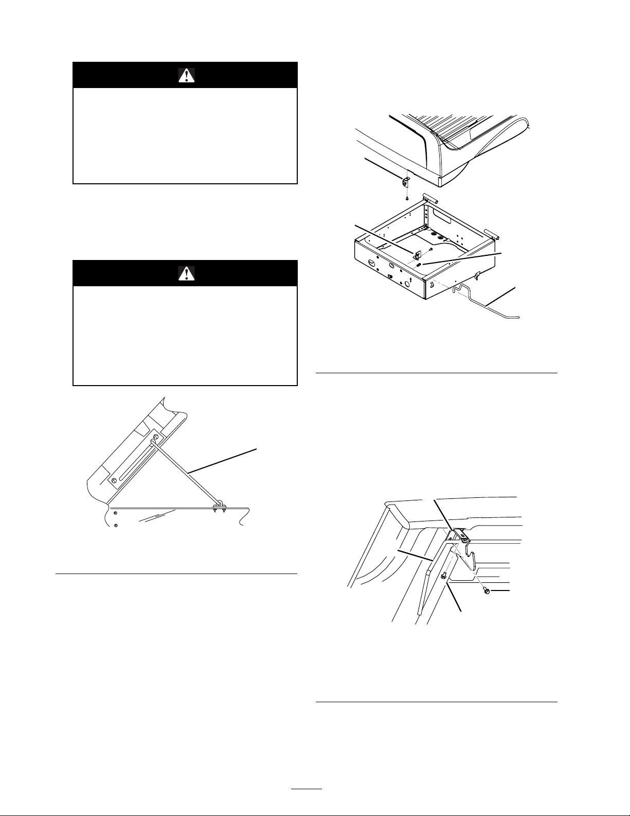
2. Raise the bed. Rotate the latch rod upward and
raise the box with the other hand.
3. Raise the box to its full height; then lower it
slightly to engage the prop rod (Figure 1).
Araisedboxcouldfallandinjurepersons
that are working beneath it.
Remove the 2 flange head screws securing each
side of the latch rod bracket to the front of the
rear frame ( Figure 2).
2
1
4
3
G001319
• Always use the prop rod to hold the
box up before working under the box.
• Remove any load material from the
box before raising it.
1
G001318
Figure 1
1. Prop rod
4. Disconnect the battery cables from the batter y.
5. Remove the rubber strap securing the battery
to the battery base. Lift the battery out of the
battery base.
For machines with Serial numbers 259999999 and
lower:
Figure 2
1. Latch rod b
2. Latch hook
racket
3. Latch rod
4. Spring
For machines with Serial numbers 260000001 and
up:
Remove the 2 flange head screws securing each
side of the latch rod bracket to the underside and
front face of the box (Figure 3). Retain all parts
for future use.
1
2
4
G001320
Figure 3
1. Latch rod bracket 3. Flange head screw, inside
2. Latch rod 4. Flange head screw,
3
front face of box
underside of box
2
Page 3
Step
2
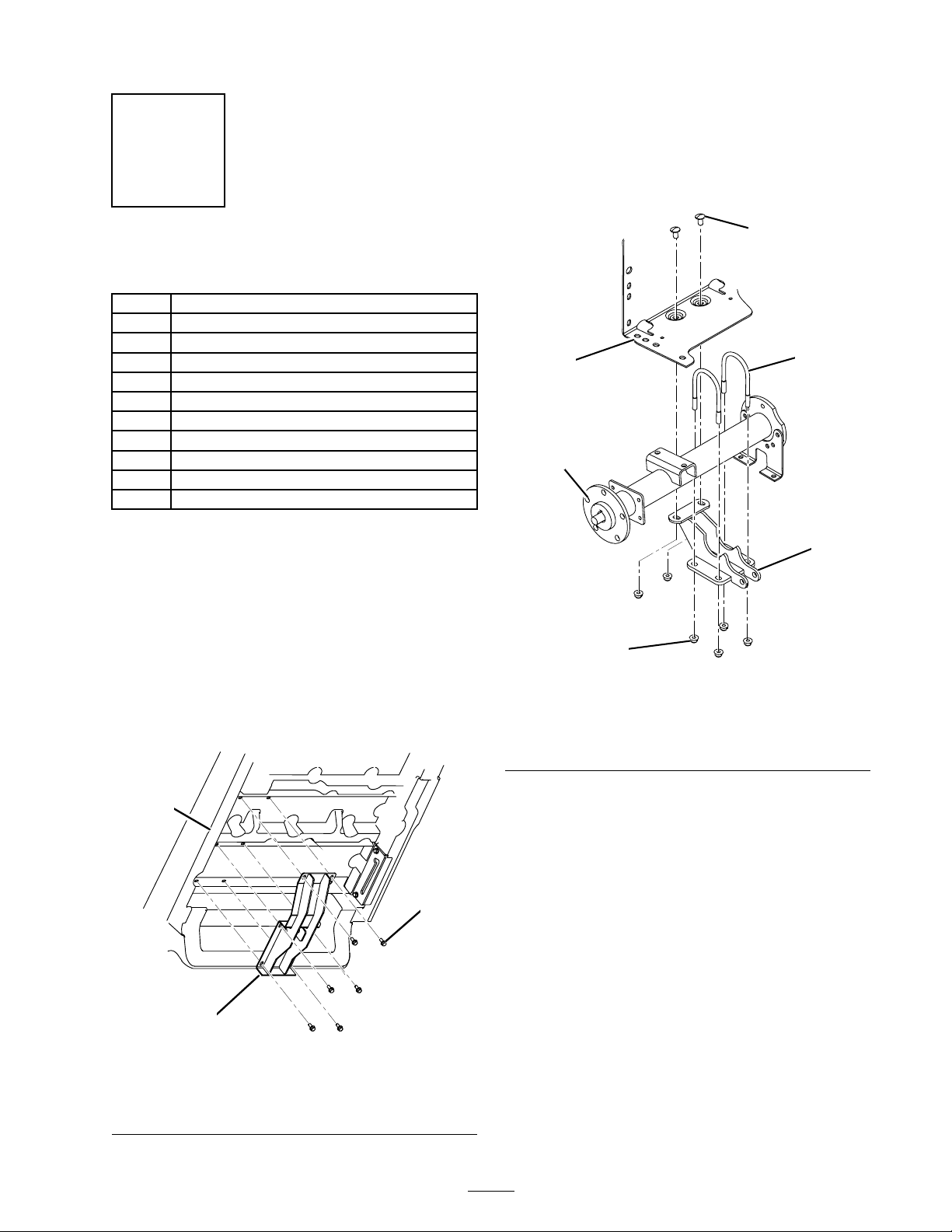
3. Loosely mount the lift cylinder support to
the right end of the rear axle with 2 U-bolts
and 4 flange nuts (3/4 inch) while aligning the
mounting holes with the holes in the battery
tray (Figure 5).
Installing th
eBedLift
Parts needed for this step:
1
Lift bracket, upper
4
Flange head screws (5/16 x 3/4 inch)
1
Lift cylinder support
1
Lift actuator
2
U-bolts
6
Flange nut (3/4 inch)
2
Carriage bolts (3/8 x 3/4 inch)
1
Clevis pin
1
Cotter pin
1
Nylon washer
3
Steel washer
Procedure
1. Remove the screws from the braces on the
underside of the box in the positions shown
in (Figure 4).
2. Mount the upper lift bracket to the underside
of the box with 6 flange head screws (5/16
x 3/4 inch) from loose parts and removed
previously. Position the bracket as shown in
Figure 4.
G001322
5
3
2
6
Figure
1. Lift cy
2. Right end of the axle 5. Carriage bolt, 3/8 x 3/4
3. Rear frame battery tray 6. Flange nut, 3/4 inch
linder support
5
4. U-bolt
inch
4
1
1
3
G001321
2
Figure 4
1. Bed 3. Flange head screw, 5/16 x
3/4 inch
2. Upper lift bracket
4. Secure the lift cylinder support to the rear
frame with 2 carriage bolts (3/8 x 3/4 inch)
and 2 flange nuts (3/4 inch). Tighten the 4
flange nuts on the U-bolts equally to make sure
the bracket is aligned to the axle. Tighten the
two nuts securing the rear of the bracket to the
rear frame (Figure 5).
5. Mount the bottom end of the lift actuator to
the lift cylinder support with a clevis pin and
3
Page 4

cotter pin. Position the components as shown
in Figure 6.
6
5
Step
3
2
G001323
3
Figure 6
1. Actuator
2. Lift cylinder support 5. Nylon washer
3. Clevis pi
n
4. Cotter pin
6. Steel w as
hers
Installing th
eSwitch
Parts needed for this step:
1
1
Switch
1Fuse,15amp
1
Clevis pin
1
Cotter pin
Procedure
1. Remove the plug from the hole in the right
side of the dash (Figure 7).
4
Note: If the hole in the dash is in use,
measure over 1/2 inch (13 mm) and cut
another 0.835 inch x 1.46 inch (21 mm x 35
mm) rectangular hole in t he dash. Make sure
not to damag e any existing components behind
the dash when cutting the hole.
3
6. Slide a nylon washer onto the actuator rod,
then slide on one steel washer.
Note: Additional steel washers are provided
and can be used to adjust the lower stop of the
actuator rod.
1
2
G001324
Figure 7
1. Plugged hole
2. Switch
3. Cut new hole (if required)
2. Plug the switch into the harness connector in
the dash. Insert the switch into the hole in the
dash (Figure 7).
3. Remove the cover to expose the fuse block.
Install a new fuse (15 amp) into the open slot
in the fuse block. Install the cover.
4
Page 5

4. Plug the actuator harness into the vehicle
harness connector, located near the fuse block.
5. Install the battery and connect the cables.
6. Press the switch upward to extend the actuator
rod until it is aligned with the mounting holes
in the upper lift bracket. Secure the rod to the
bracket with the clevis pin and cotter pin.
7. Remove the screws and clip securing the prop
rod to the frame rail (Figure 8).
3
1
2
G001325
Figure 8
1. Prop rod 3. Prop rod bracket
2. Prop rod clip
8. Remove the screws securing the prop rod
bracket to the underside of the box. Remove
the retainer securing the rod t o the bracket and
remove the rod (Figure 8). Retain the prop rod
components for future use.
Note: If the electric box lift is ever removed,
install the prop rod, prop rod clip, and prop
rod bracket.
5
Page 6

Operation
Raising the Bed
Driving the ve
may cause the
The box struc
the box is rai
time while o
• Only operat
box is down.
•Afteraload
cargo box.
1. Turn the ignition key to the On position.
2. Push the top of the switch to raise the box.
Important: When a ratcheting noise is
heard, the box lift is completely extended
or retracted. Do not continue pressing the
switch.
hicle with the cargo box raised
vehicle to tip or roll easier.
ture may become damaged if
sed for an extended period of
perating the vehicle.
e the vehicle when the cargo
has been dumped, lower the
Lowering the Bed
The weight of the box may be heavy. Hands
or other body parts could be crushed.
Keep hands and other body parts clear when
lowering the box.
1. Push the bottom of the switch to lower the
box.
Note: The bed will deform slightly before
the actuator clutch begins to engage. If the
bed floor deforms more than 1/4 inch add
additional steel washers to the raise the lower
stop of the actuator rod. When bed is pulled
tight to the vehicle frame, but the bed floor
does not deform more than 1/4 inch the lift
has been adjusted correctly.
2. Turn the ignition key to the Off position and
remove the key.
6
Page 7

Page 8

 Loading...