

Page 1

Form No. 3350-668 Rev B
Workman) 1100 Utility Vehicle
Model No. 07252—Serial No. 240000001 and Up
Model No. 07252TC—Serial No. 240000001 and Up
Operator’s Manual
Register your product at www.Toro.com
Original Instructions (EN, GB)
Page 2

Warning
CALIFORNIA
Proposition 65 Warning
The engine exhaust from this product contains
chemicals known to the State of California to cause
cancer, birth defects, or other reproductive harm.
Important The engine in this product is not equipped
with a spark arrester muffler. It is a violation of California
Public Resource Code Section 4442 to use or operate this
engine on any forest-covered, brush-covered, or
grass-covered land as defined in CPRC 4126. Other states
or federal areas may have similar laws.
This spark ignition system complies with Canadian
ICES-002.
Ce système d’allumage par étincelle de véhicule est
conforme à la norme NMB-002 du Canada.
Contents
Page
Introduction 3. . . . . . . . . . . . . . . . . . . . . . . . . . . . . . . . .
Safety 3. . . . . . . . . . . . . . . . . . . . . . . . . . . . . . . . . . . . . .
Safe Operating Practices 4. . . . . . . . . . . . . . . . . . . .
Before Operating 4. . . . . . . . . . . . . . . . . . . . . . . . . .
While Operating 4. . . . . . . . . . . . . . . . . . . . . . . . . . .
Maintenance 7. . . . . . . . . . . . . . . . . . . . . . . . . . . . . .
Sound Pressure 7. . . . . . . . . . . . . . . . . . . . . . . . . . . .
Sound Power 7. . . . . . . . . . . . . . . . . . . . . . . . . . . . .
Vibration 7. . . . . . . . . . . . . . . . . . . . . . . . . . . . . . . . .
Slope Chart 8. . . . . . . . . . . . . . . . . . . . . . . . . . . . . . .
Safety and Instruction Decals 9. . . . . . . . . . . . . . . . .
Specifications 11. . . . . . . . . . . . . . . . . . . . . . . . . . . . . . . .
Optional Equipment 11. . . . . . . . . . . . . . . . . . . . . . . .
Setup 12. . . . . . . . . . . . . . . . . . . . . . . . . . . . . . . . . . . . . .
Loose Parts 12. . . . . . . . . . . . . . . . . . . . . . . . . . . . . . .
Installing the Rear Wheels 12. . . . . . . . . . . . . . . . . . .
Installing the Front Wheels 13. . . . . . . . . . . . . . . . . .
Installing the Steering Wheel 13. . . . . . . . . . . . . . . . .
Installing the Bumper 13. . . . . . . . . . . . . . . . . . . . . . .
Installing the Seats 14. . . . . . . . . . . . . . . . . . . . . . . . .
Installing the Hitch 14. . . . . . . . . . . . . . . . . . . . . . . . .
Installing the Cargo Box 14. . . . . . . . . . . . . . . . . . . .
Activating the Battery 15. . . . . . . . . . . . . . . . . . . . . .
Checking the Crankcase Oil 15. . . . . . . . . . . . . . . . . .
Checking the Tire Pressure 16. . . . . . . . . . . . . . . . . .
Fuel Tank 16. . . . . . . . . . . . . . . . . . . . . . . . . . . . . . . .
Checking the Transmission Oil 17. . . . . . . . . . . . . . .
W 2003 by The Toro Company
8111 Lyndale Avenue South
Bloomington, MN 55420-1196
Operation 17. . . . . . . . . . . . . . . . . . . . . . . . . . . . . . . . . . .
Think Safety First 17. . . . . . . . . . . . . . . . . . . . . . . . . .
Controls 17. . . . . . . . . . . . . . . . . . . . . . . . . . . . . . . . .
Pre-Starting Checks 19. . . . . . . . . . . . . . . . . . . . . . . .
Starting the Engine 19. . . . . . . . . . . . . . . . . . . . . . . . .
Stopping the Vehicle 19. . . . . . . . . . . . . . . . . . . . . . .
Parking the Vehicle 19. . . . . . . . . . . . . . . . . . . . . . . .
Cargo Bed 19. . . . . . . . . . . . . . . . . . . . . . . . . . . . . . . .
Tailgate Latches 20. . . . . . . . . . . . . . . . . . . . . . . . . . .
New Vehicle Break-In 20. . . . . . . . . . . . . . . . . . . . . .
Loading the Cargo Box 20. . . . . . . . . . . . . . . . . . . . .
Transporting the Vehicle 21. . . . . . . . . . . . . . . . . . . .
Towing the Vehicle 21. . . . . . . . . . . . . . . . . . . . . . . . .
Towing a Trailer 21. . . . . . . . . . . . . . . . . . . . . . . . . . .
Maintenance 22. . . . . . . . . . . . . . . . . . . . . . . . . . . . . . . . .
Recommended Maintenance Schedule 22. . . . . . . . .
Daily Maintenance Checklist 23. . . . . . . . . . . . . . . . .
Maintaining the Vehicle under Special Operating
Conditions 24. . . . . . . . . . . . . . . . . . . . . . . . . . . . . .
Jacking the Vehicle 24. . . . . . . . . . . . . . . . . . . . . . . . .
Checking and Adjusting Neutral 25. . . . . . . . . . . . . .
Servicing the Engine Oil 25. . . . . . . . . . . . . . . . . . . .
Cleaning the Engine Cooling Areas 26. . . . . . . . . . . .
Servicing the Air Cleaner 26. . . . . . . . . . . . . . . . . . . .
Greasing the Machine 27. . . . . . . . . . . . . . . . . . . . . .
Servicing the Brakes 27. . . . . . . . . . . . . . . . . . . . . . .
Inspecting the Tires 28. . . . . . . . . . . . . . . . . . . . . . . .
Adjusting the Front Suspension 28. . . . . . . . . . . . . . .
Adjusting Front Wheel Toe-In 29. . . . . . . . . . . . . . . .
Servicing the Drive Belt 30. . . . . . . . . . . . . . . . . . . . .
Adjusting the Starter Generator Belt 30. . . . . . . . . . .
Maintaining the Primary Drive Clutch 30. . . . . . . . . .
Servicing the Fuel System 31. . . . . . . . . . . . . . . . . . .
Servicing the Spark Plug 31. . . . . . . . . . . . . . . . . . . .
Changing the Transaxle Fluid 32. . . . . . . . . . . . . . . .
Replacing the Fuses 32. . . . . . . . . . . . . . . . . . . . . . . .
Replacing the Headlights 32. . . . . . . . . . . . . . . . . . . .
Servicing the Battery 33. . . . . . . . . . . . . . . . . . . . . . .
Washing the Vehicle 34. . . . . . . . . . . . . . . . . . . . . . . .
Schematics 35. . . . . . . . . . . . . . . . . . . . . . . . . . . . . . . . . .
The Toro General Commercial Products Warranty 36. . .
Contact us at www.Toro.com
All Rights Reserved
2
Printed in the USA
Page
Page 3
Introduction
Caution signals a hazard that may cause minor or moderate
injury if you do not follow the recommended precautions.
Read this manual carefully to learn how to operate and
maintain your product properly. The information in this
manual can help you and others avoid injury and product
damage. Although Toro designs and produces safe
products, you are responsible for operating the product
properly and safely.
You may contact Toro directly at www.Toro.com for
product and accessory information, help finding a dealer, or
to register your product.
Whenever you need service, genuine Toro parts, or
additional information, contact an Authorized Service
Dealer or Toro Customer Service and have the model and
serial numbers of your product ready. Figure 1 illustrates
the location of the model and serial numbers on the
product.
1
This manual uses two other words to highlight information.
Important calls attention to special mechanical
information and Note: emphasizes general information
worthy of special attention.
Safety
Improper use or maintenance by the operator or owner
can result in injury. To reduce the potential for injury,
comply with these safety instructions and always pay
attention to the safety alert
CAUTION, WARNING, or DANGER—“personal
safety instruction.” Failure to comply with the
instruction may result in personal injury or death.
Supervisors, operators, and service persons should be
familiar with the following standards and publications (the
material may be obtained from the address shown):
• Flammable and Combustible Liquids Code:
ANSI/NFPA 30
• National Fire Protection Association:
ANSI/NFPA #505; Powered Industrial Trucks
National Fire Prevention Association
Barrymarch Park
Quincy, Massachusetts 02269 U.S.A.
symbol, which means
m–6044
Figure 1
1. Model and serial number plate
Write the product model and serial numbers in the space
below:
Model No.
Serial No.
This manual identifies potential hazards and has special
safety messages that help you and others avoid personal
injury and even death. Danger, Warning, and Caution are
signal words used to identify the level of hazard. However,
regardless of the hazard, be extremely careful.
Danger signals an extreme hazard that will cause serious
injury or death if you do not follow the recommended
precautions.
Warning signals a hazard that may cause serious injury or
death if you do not follow the recommended precautions.
• ANSI/ASME B56.8 Personal Burden Carriers
American National Standards Institute, Inc.
1430 Broadway
New York, New York 10018 U.S.A.
• SAE J2258 Light Utility Vehicle
SAE International
400 Commonwealth Drive
Warrendale, PA 15096–0001 U.S.A.
• ANSI/UL 558; Internal Combustion Engine Powered
Industrial Trucks
American National Standards Institute, Inc.
1430 Broadway
New York, New York 10018 U.S.A.
or
Underwriters Laboratories
333 Pfingsten Road
Northbrook, Illinois 60062 U.S.A.
3
Page 4

Safe Operating Practices
Warning
The Workman is an off-highway vehicle only and
is not designed, equipped, or manufactured for use
on public streets, roads, or highways.
• Wearing safety glasses, safety shoes, long pants and a
helmet is advisable and required by some local safety
and insurance regulations.
• Avoid driving when it is dark, especially in unfamiliar
areas. If you must drive when it is dark, be sure to drive
cautiously, use the headlights, and even consider adding
additional lights.
• Be extremely careful when operating around people.
Always be aware of where bystanders might be.
Supervisor’s Responsibilities
• Make sure that operators are thoroughly trained and
familiar with the Operator’s Manual and all labels on
the vehicle.
• Be sure to establish your own special procedures and
work rules for unusual operating conditions (e.g. slopes
too steep for vehicle operation).
Before Operating
• Operate the machine only after reading and
understanding the contents of this manual.
• Never allow children to operate the vehicle. Anyone
who operates the vehicle should have a motor vehicle
license.
• Never allow other adults to operate the vehicle without
first reading and understanding the Operator’s Manual.
Only trained and authorized persons should operate this
vehicle. Make sure that all operators are physically and
mentally capable of operating the vehicle.
• This vehicle is designed to carry only you, the operator,
and one passenger in the seat provided by the
manufacturer. Never carry any other passengers on the
vehicle.
• Never operate the vehicle when under the influence of
drugs or alcohol. Even prescription drugs and cold
medicines can cause drowsiness.
• Do not drive the vehicle when you are tired. Be sure to
take occasional breaks. It is very important that you stay
alert at all times.
• Become familiar with the controls and know how to
stop the engine quickly.
• Keep all shields, safety devices, and decals in place. If a
shield, safety device, or decal is malfunctioning,
illegible, or damaged, repair or replace it before
operating the machine.
• Always wear substantial shoes. Do not operate the
machine while wearing sandals, tennis shoes or
sneakers. Do not wear loose fitting clothing or jewelry
which could get caught in moving parts and cause
personal injury.
• Before operating the vehicle, always check the
designated areas of the vehicle that are stated in the
pre-starting section of this manual. If something is
wrong, do not use the vehicle. Make sure that the
problem is corrected before the vehicle or attachment is
operated.
• Since gasoline is highly flammable, handle it carefully.
– Use an approved gasoline container.
– Do not remove the cap from the fuel tank when the
engine is hot or running.
– Do not smoke while handling gasoline.
– Fill the fuel tank outdoors, and fill it to about 1 inch
(25 mm) below the top of the tank (the bottom of
the filler neck). Do not overfill it.
– Wipe up any spilled gasoline.
While Operating
Warning
Engine exhaust contains carbon monoxide, which
is an odorless, deadly poison that can kill you.
Do not run engine indoors or in an enclosed area.
• The operator and passenger should remain seated
whenever the vehicle is in motion. The operator should
keep both hands on the steering wheel whenever
possible, and the passenger should use the hand holds
provided. Keep your arms and legs within the vehicle
body at all times.
• Drive slower and turn less sharply when you are
carrying a passenger. Remember your passenger may
not be expecting you to brake or turn and may not be
ready.
• Always watch out for and avoid low overhangs such as
tree limbs, door jambs, and over-head walkways. Make
sure there is enough room over head to easily clear the
vehicle and your head.
4
Page 5

• Always shift into neutral and apply the parking brake
before leaving an idling vehicle, or else the vehicle may
creep.
• Failure to operate the vehicle safely may result in an
accident, tip over of the vehicle, and serious injury or
death. Drive carefully. To prevent tipping or loss of
control:
• Before getting off of the seat:
A. Stop the movement of the machine.
B. Set the parking brake.
C. Turn the ignition key to Off.
D. Remove the ignition key.
– Use extreme caution, reduce speed, and maintain a
safe distance around sand traps, ditches, creeks,
ramps, unfamiliar areas, or any areas that have
abrupt changes in ground conditions or elevation.
– Watch for holes or other hidden hazards.
– Use extra caution when operating the vehicle on wet
surfaces, in adverse weather conditions, at higher
speeds, or with a full load. Stopping time and
distance will increase with a full load.
– Avoid sudden stops and starts. Do not go from
reverse to forward or forward to reverse without
first coming to a complete stop.
– Slow down before turning. Do not attempt sharp
turns or abrupt maneuvers or other unsafe driving
actions that may cause a loss of vehicle control.
– When dumping, do not let anyone stand behind the
vehicle and do not dump the load on anyone’s feet.
Release the tailgate latches from the side of the box,
not from behind.
– Only operate the vehicle when the cargo box is
down and latched.
– Before backing up, look to the rear and ensure that
no one is behind you. Back up slowly.
– Watch out for traffic when you are near or crossing
roads. Always yield the right of way to pedestrians
and other vehicles. This vehicle is not designed for
use on streets or highways. Always signal your turns
or stop early enough so that other people know what
you plan to do. Obey all traffic rules and
regulations.
Note: If the vehicle is on an incline, block the wheels after
getting off of the vehicle.
Braking
• Slow down before you approach an obstacle. This gives
you extra time to stop or turn away. Hitting an obstacle
can damage the vehicle and its contents. More
important, it can injure you and your passenger.
• Gross Vehicle Weight (GVW) has a major impact on
your ability to stop and/or turn. Heavy loads and
attachments make a vehicle harder to stop or turn. The
heavier the load, the longer it takes to stop.
• Decrease the vehicle speed if the cargo box has been
removed and there is no attachment on the vehicle. The
braking characteristics change and fast stops may cause
the rear wheels to lock up, which may affect the control
of the vehicle.
• Turf and pavement are much more slippery when they
are wet. It can take 2 to 4 times as long to stop on wet
surfaces as on dry surfaces. If you drive through
standing water deep enough to get the brakes wet, they
will not work well until they are dry. After driving
through water, you should test the brakes to make sure
they work properly. If they do not, drive slowly while
putting light pressure on the brake pedal. This will dry
the brakes out.
Operating on Hills
Warning
– The electrical and exhaust systems of the vehicle
can produce sparks capable of igniting explosive
materials. Never operate the vehicle in or near an
area where there is dust or fumes in the air which
are explosive.
– If you are ever unsure about safe operation, stop
work and ask your supervisor.
• Do not touch the engine or muffler while the engine is
running or soon after it has stopped. These areas may be
hot enough to cause burns.
• If the machine ever vibrates abnormally, stop
immediately, wait for all motion to stop, and inspect the
vehicle for damage. Repair all damage before
commencing operation.
Operating the vehicle on a hill may cause tipping
or rolling of the vehicle, or the engine may stall
and you could lose headway on the hill. This could
result in personal injury.
• Do not exceed slopes greater than 125.
• Do not accelerate quickly or slam on the brakes
when backing down a hill, especially with a load.
• If the engine stalls or you lose headway on a hill,
slowly back straight down the hill. Never
attempt to turn the vehicle around.
• Never drive across a steep hill; always drive
straight up or down or go around the hill.
• Avoid turning on a hill.
• Reduce your load and the speed of the vehicle.
• Avoid stopping on hills, especially with a load.
5
Page 6

These extra cautions need to be taken when operating the
vehicle on a hill:
• Slow down before starting up or down a hill.
• If the engine stalls or you begin to lose headway while
climbing a hill, gradually apply the brakes and slowly
back straight down the hill.
• Turning while traveling up or down hills can be
dangerous. If you have to turn while on a hill, do it
slowly and cautiously. Never make sharp or fast turns.
• Heavy loads affect stability. Reduce the weight of the
load and your speed when operating on hills or if the
load has a high center of gravity. Secure the load to
prevent it from shifting and take extra care when
hauling loads that shift easily (liquid, rock, sand, etc.).
• Avoid stopping on hills, especially with a load.
Stopping while going down a hill will take longer than
stopping on level ground. If the vehicle must be
stopped, avoid sudden speed changes, which may
initiate tipping or rolling of the vehicle. Do not slam on
the brakes when rolling backward, as this may cause the
vehicle to overturn.
• Travel straight up and down slopes whenever possible.
• We strongly recommend installing the optional ROPS
Kit when operating on hilly terrain.
Operating on Rough Terrain
Reduce speed and load when operating on rough terrain,
uneven ground, and near curbs, holes, and other sudden
changes in terrain. Loads may shift, causing the vehicle to
become unstable.
• Do not carry loads which exceed the load limits
described on the vehicle weight label; refer to
Specifications, page 11, for vehicle weight limits. The
load rating is for level surfaces only.
• Reduce the weight of the load when operating on hills
and rough terrain to avoid tipping or overturning of the
vehicle.
• Reduce the weight of the load if the center of gravity is
high. Items such as bricks, fertilizer, or landscape
timbers stack higher in the box. The higher a load is
stacked, the more likely the vehicle is to tip over.
Distribute the load as low as possible, making sure that
the load does not affect rear visibility.
• Position the weight of the load evenly from side to side.
If you position the load toward one of the sides, the
vehicle is more likely to tip over while turning.
• Position the weight of a load evenly from front to back.
If you position the load behind the rear axle, it will
reduce the weight on the front wheels. This may result
in a loss of steering control or cause the vehicle to tip
over on hills or bumpy terrain.
• Use extra caution if the load exceeds the dimensions of
the box and when handling off-center loads that cannot
be centered. Keep loads balanced and secure to prevent
them from shifting.
• Always secure loads so that they do not shift. If a load
is not secured, or you are transporting a liquid in a large
container such as a sprayer, the load can shift. This
shifting happens most often while turning, going up or
down hills, suddenly changing speeds, or while driving
over rough surfaces. Shifting loads can cause the
vehicle to tip over.
We strongly recommend installing the optional ROPS Kit
when operating on rough terrain.
Warning
Sudden changes in terrain may cause abrupt
steering wheel movement, possibly resulting in
hand and arm injuries.
• Reduce your speed when operating on rough
terrain and near curbs.
• Grip the steering wheel loosely around the
perimeter. Keep your hands clear of the steering
wheel spokes.
Loading and Dumping
The weight and position of the cargo and passenger can
change the vehicle center of gravity and vehicle handling.
To avoid loss of control and personal injury, follow these
guidelines:
Warning
The weight of the box may be heavy. Hands or
other body parts could be crushed.
• Keep hands and other body parts clear when
lowering the box.
• Do not dump materials on bystanders.
• Never dump a loaded cargo box while the vehicle is
sideways on a hill. The change in weight distribution
may cause the vehicle to overturn.
• When operating with a heavy load in the cargo box,
reduce your speed and allow for sufficient braking
distance. Do not suddenly apply the brakes. Use extra
caution on slopes.
• Be aware that heavy loads increase your stopping
distance and reduce your ability to turn quickly without
tipping over.
• The rear cargo space is intended for load carrying
purposes only, not for passengers.
6
Page 7

• Never overload your vehicle. The name plate (located
under dash on center column) shows load limits for the
vehicle. Never overload the attachments or exceed the
Gross Vehicle Weight (GVW).
Vibration
This unit does not exceed a hand/arm vibration level of
2
2.5 m/s
Directive 98/37/EC.
, based on measurements of identical machines per
Maintenance
• Only qualified and authorized personnel shall be
permitted to maintain, repair, adjust, or inspect the
vehicle.
• Before servicing or making adjustments to the machine,
stop the engine, set the parking brake, and remove the
key from the ignition to prevent someone from
accidentally starting the engine.
• To make sure that the entire machine is in good
condition, keep all nuts, bolts, and screws properly
tightened.
• To reduce the potential for fire, keep the engine area
free of excessive grease, grass, leaves, and
accumulation of dirt.
• Never use an open flame to check the level or leakage
of fuel or battery electrolyte.
• If the engine must be running to perform a maintenance
adjustment, keep your hands, feet, clothing, and any
parts of your body away from the engine and any
moving parts. Keep everyone away.
• Do not use open pans of fuel or flammable cleaning
fluids for cleaning parts.
This unit does not exceed a whole body vibration level of
2
0.5 m/s
Directive 98/37/EC.
, based on measurements of identical machines per
• Do not adjust the ground speed governor. To ensure
safety and accuracy, have an Authorized Toro
Distributor check the ground speed.
• If major repairs are ever needed or assistance is
required, contact an Authorized Toro Distributor.
• To be sure of optimum performance and safety, always
purchase genuine Toro replacement parts and
accessories. Replacement parts and accessories made by
other manufacturers could be dangerous. Altering this
vehicle in any manner that may affect vehicle operation,
performance, durability, or its use, may result in injury
or death. Such use could void the product warranty.
Sound Pressure
This unit has a maximum sound pressure level at the
operator’s ear of 78 dBA, based on measurements of
identical machines per Directive 98/37/EC.
7
Page 8
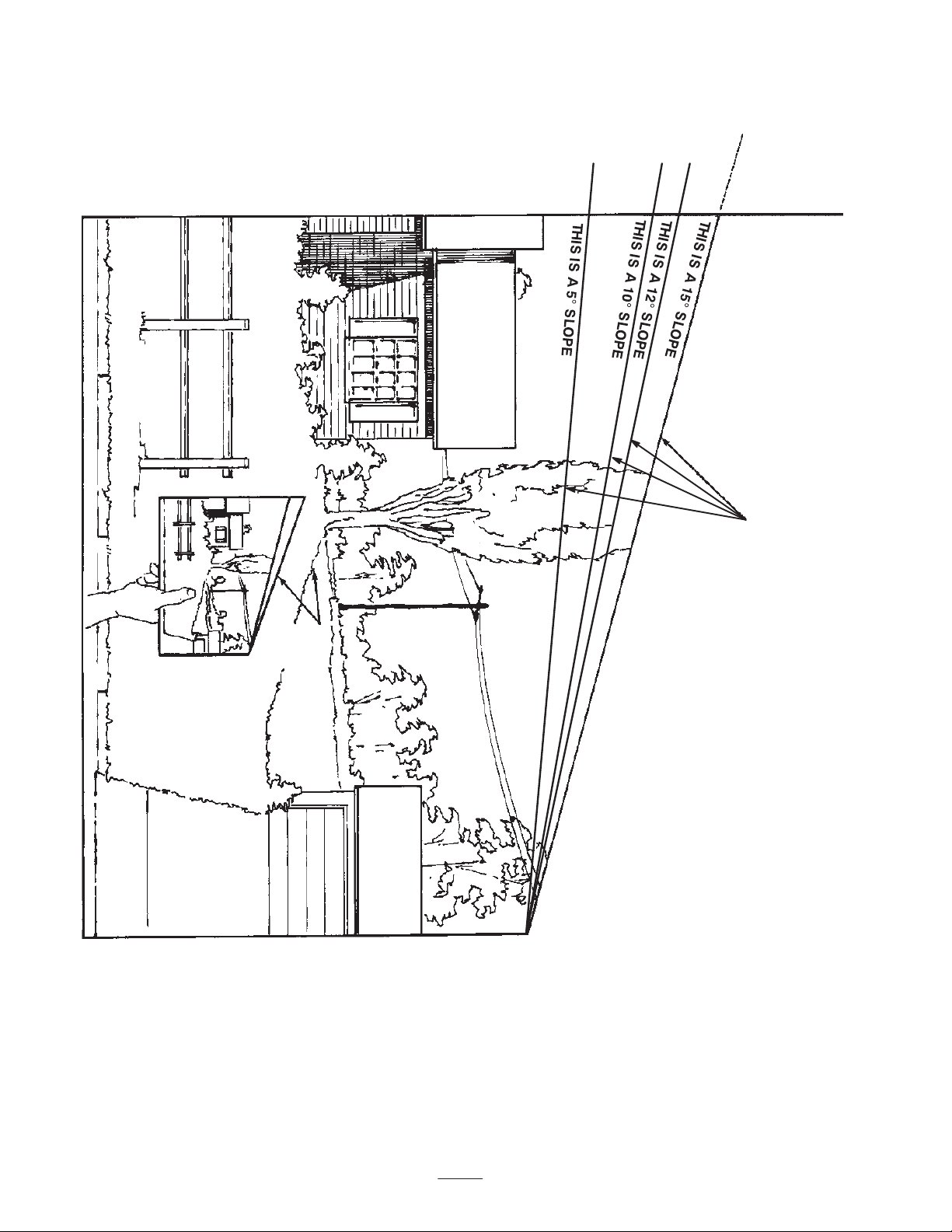
Slope Chart
ALIGN THIS EDGE WITH A VERTICAL SURFACE
(TREE, BUILDING, FENCEPOST, POLE, ETC.)
FOLD ALONG APPROPRIATE LINE.
EXAMPLE: COMPARE
SLOPE WITH FOLDED
EDGE.
8
Page 9
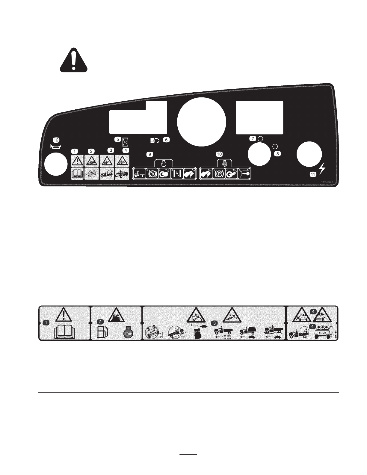
Safety and Instruction Decals
Safety decals and instructions are easily visible to the operator and are located near any area
of potential danger. Replace any decal that is damaged or lost.
107-0699
1. Warning—read the Operator’s Manual.
2. Collision hazard—do not operate the vehicle on public streets, roads, or highways.
3. Falling hazard—do not carry passengers in the cargo bed.
4. Falling hazard—do not allow children to operate the vehicle.
5. Hour meter
6. Headlights
7. Off (ignition)
8. On (ignition)
9. To start the engine, sit on the operator’s seat, release the parking brake, turn the ignition key on, pull the choke lever out (if needed), and
press the accelerator pedal.
10. To stop the engine, release the accelerator pedal, set the parking brake, turn the ignition key off, and remove the ignition key.
11. Electrical power (power point)
12. Horn
99-7344
1. Warning—read the Operator’s Manual.
2. Fire hazard—before fueling, stop the engine.
3. Tipping hazard—do not drive the vehicle across or up a slope greater than 12 degrees; drive slowly when turning, when carrying a full or
heavy load, and when driving on rough terrain; keep the vehicle speed under 16 mph (26 km/h).
4. Falling and arm/leg injury hazards—do not carry passengers in the cargo bed and keep arms and legs inside of the vehicle at all times.
9
Page 10
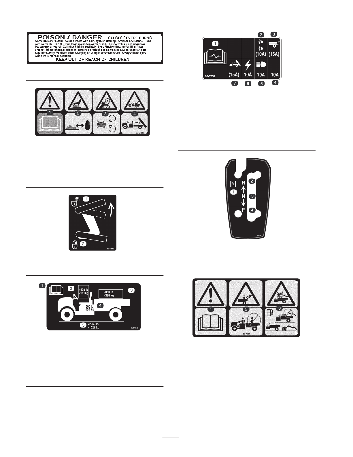
1. Warning—read the
Operator’s Manual.
2. Hot surface/burn
hazard—stay a safe
distance from the hot
surface.
26-7390
99-7345
99-7352
1. Read the Operator’s Manual for information on fuses.
2. 10 amp. fuse for the optional Road Light Kit
3. 15 amp. fuse for the optional Rear Lift Kit
4. 10 amp. fuse—open
5. 10 amp. fuse for the headlights
6. 10 amp. fuse for the ignition system
7. 15 amp. fuse for the optional Electric Bed Lift Kit
3. Entanglement hazard,
belt—stay away from
moving parts.
4. Crushing hazard, cargo
box—use the prop rod to
support the cargo bed.
99-7349
1. Unlock the cargo bed 2. Lock the cargo bed
104-6855
1. Read the Operator’s Manual.
2. The maximum combined operator and passenger weight is
400 lb. (181 kg.).
3. The maximum cargo weight is 850 lb. (386 kg).
4. The base weight of the vehicle is 1000 lb. (454 kg).
5. The maximum gross vehicle weight is 2250 lb. (1021 kg).
99-7952
1. Choke
2. Reverse
3. Neutral
4. Forward
99-7954
1. Warning—read the Operator’s Manual.
2. Falling hazard—do not carry passengers in the cargo bed.
3. Explosion hazard, static discharge into fuel container—do not
fill fuel containers in the cargo bed; place fuel containers on the
ground before filling.
10
Page 11

99-7350
1. Maximum tongue weight is 50 lb. (23 kg); maximum trailer
weight is 400 lb. (181 kg).
Specifications
Note: Specifications and design are subject to change without notice.
Base weight
Rated capacity
(on level ground)
Maximum gross vehicle
weight (GVW)
(on level ground)
Maximum cargo capacity
(on level ground)
Tow capacity:
Standard Hitch Tongue weight 50 lb. (23 kg) Maximum trailer weight 400 lb. (182 kg)
Heavy Duty Hitch Tongue weight 100 lb. (45 kg) Maximum trailer weight 800 lb. (363 kg)
Overall width 60 inches (152.4 cm)
Overall length 117 inches (297.2 cm)
Ground clearance
Wheel base 79 inches (200.7 cm)
Wheel tread
(center line to center line)
Cargo box length
Cargo box width
Cargo box height 10 inches (25.4 cm) inside
Dry 1000 lb. (454 kg)
1250 lb. (567 kg) total, including 200 lb. (90.7 kg) operator and 200 lb. (90.7 kg)
passenger, load, trailer tongue weight, gross trailer weight, accessories, and
attachments
2250 lb. (1021 kg) total, including all of the weights listed above
850 lb. (386 kg) total, including trailer tongue weight and gross trailer weight
9-1/4 inches (23.5 cm) at the front with no load or operator
6-1/2 inches (19.7 cm) at the rear with no load or operator
49 inches (124.5 cm) in the front
48-1/4 inches (122.6 cm) in the rear
46 inches (116.8 cm) inside
51 inches (129.5 cm) outside
49 inches (124.5 cm) inside
54 inches (137.2 cm) outside
Optional Equipment
The Toro Company has optional equipment and accessories that you can purchase separately and install on your vehicle.
Contact your Authorized Service Dealer for a complete list of optional equipment that is currently available for your vehicle.
11
Page 12

Setup
Note: Determine the left and right sides of the machine from the normal operating position.
Loose Parts
Note: Use the chart below to verify that all parts have been shipped.
Description
Wheel assembly 2 Installing the rear wheels (Model No. 07252TC)
Wheel assembly
Washer
Dust cap
Steering wheel 1 Installing the steering wheel (Model No. 07252TC)
Bumper 1 Installing the bumper (Model No. 07252TC)
Hitch 1 Installing the hitch (Model No. 07252TC)
Seat 2 Installing the seats (Model No. 07252TC)
Cargo box
Right-hand pivot bracket
Left-hand pivot bracket
Flange head screw, 3/8 x 1 inch
Bolt, 5/16 x 3/4 inch
Flange nut, 5/16 inch
Key 2 Use in the ignition switch.
Operator’s Manual
Engine Operator’s Manual
Qty. Use
2
2
2
1
1
1
4
1
1
1
1
Installing the front wheels (Model No. 07252TC)
Installing the cargo box (Model No. 07252TC)
Read before operating the machine.
Operator Video 1 Watch before operating the machine.
Parts Catalog 1 Use for ordering replacement parts.
Registration Card 1 Complete and return to Toro.
Predelivery Inspection Form 1 Complete and file in your customer history portfolio.
Installing the Rear Wheels
Note: This procedure is only needed for Model No.
07252TC.
1. Remove the fasteners securing the wheels.
2. Remove the shipping bracket secured to the wheel
studs.
3. Mount the wheels with the previously removed
fasteners (Fig. 2) and torque to 45–65 ft.-lb.
(61–88 N⋅m).
1. Wheel assembly
2. Wheel nut
3
Figure 2
3. Wheel stud
1
2
12
Page 13

Installing the Front Wheels
Note: This procedure is only needed for Model No.
07252TC.
1. Remove the fasteners securing the wheels.
2. Remove the shipping bracket from the spindles.
3. Apply Loctite (blue) to the screw threads.
4. Mount the wheels with the previously removed
fasteners (Fig. 3) and torque the bolts to 135–165 ft.-lb.
(183–224 N⋅m)
3. Secure the steering wheel to the shaft with the nut
(Fig. 4).
2
1
3
4
1
3
4
2
5
Figure 3
1. Tire and wheel assembly
2. Spindle
3. Small washer
4. Large washer
5. Screw
6. Dust cap
Installing the Steering Wheel
Note: This procedure is only needed for Model No.
07252TC.
1. Remove the nut and lock washer from the steering
shaft.
2. Slide the steering wheel and washer onto the shaft.
Position the steering wheel on the shaft so that the cross
beam is horizontal when the tires are pointed straight
ahead and the thicker spoke of the steering wheel is
downward.
Figure 4
1. Steering wheel
2. Nut
3. Washer
4. Foam seal
6
Installing the Bumper
Note: This procedure is only needed for Model No.
07252TC.
1. Remove the 2 bolts, washers, and nuts secured to the
front of the frame.
2. Align the mounting holes and secure the bumper to the
frame with the fasteners previously removed (Fig. 5).
1
Figure 5
1. Bumper
13
Page 14

Installing the Seats
Note: This procedure is only needed for Model
No. 07252TC.
Insert the seat bracket into the seat base opening and pivot
the seat downward (Fig. 6).
1
2
Figure 7
1. Hitch 2. Pivot bracket
1
2
Figure 6
1. Seat bracket 2. Seat base
Installing the Hitch
Note: This procedure is only needed for Model No.
07252TC.
1. Remove the 4 bolts and nuts from the inside rear of the
frame.
2. Align the hitch with the mounting holes on the frame.
Secure the hitch with the screws and nuts (Fig. 7).
Installing the Cargo Box
Note: This procedure is only needed for Model
No. 07252TC.
1. Position the cargo box onto the frame. The cargo box
must lay flat and be centered.
2. Mount the left hand pivot bracket to the left rear corner
of the frame with 2 flange head screws (3/8 x 1 inch).
Position the bracket as shown in Figure 7.
3. Slide the cargo box mounting hole onto the pivot
bracket (Fig. 8).
3
1
2
Figure 8
1. Cargo box
2. Pivot bracket
4. Insert the right hand pivot bracket into the mounting
hole in the cargo box and then mount it to the frame.
5. Have another person help to raise the cargo box.
6. Loosen the bolt securing the prop rod clip to the frame
until you can slide the J-hook end of the prop rod under
the clip (Fig. 9).
14
3. Cargo box mounting hole
Page 15

3
2
Figure 9
1. Prop rod
2. Prop rod clip
7. Tighten the bolt and secure the other side of the clip
with a new bolt (5/16 x 3/4 inch) and flange nut
(5/16 inch) (Fig. 9).
8. Lower the cargo box.
3. Bolt, 5/16 x 3/4 inch
4. Flange nut, 5/16 inch
1
4
m–5813
Warning
Charging the battery produces gasses that can
explode.
Never smoke near the battery and keep sparks and
flames away from battery.
4. When the battery is charged, disconnect the charger
from the electrical outlet and battery posts.
5. Remove the filler caps. Slowly add electrolyte to each
cell until electrolyte is up to the fill line. Install the filler
caps.
Important Do not overfill the battery. Electrolyte will
overflow onto other parts of the vehicle and severe
corrosion and deterioration will result.
6. Install the battery; refer to Installing the Battery,
page 33.
Activating the Battery
Note: This procedure is only needed for Model No.
07252TC.
If the battery is not filled with electrolyte or activated, it
must be removed from the vehicle, filled with electrolyte,
and charged. Bulk electrolyte with 1.260 specific gravity
must be purchased from a local battery supply outlet.
1. Remove the battery hold-down and lift the battery out
of the battery base.
Danger
Battery electrolyte contains sulfuric acid which is a
deadly poison and causes severe burns.
• Do not drink electrolyte or allow it to contact
your skin, eyes or clothing. Wear safety glasses
to shield your eyes and rubber gloves to protect
your hands.
• Fill the battery where clean water is always
available for flushing the skin.
2. Remove the filler caps from the battery and slowly fill
each cell until electrolyte is just above the plates.
Checking the Crankcase Oil
The engine is shipped with oil in the crankcase; however,
the level of the oil must be checked before and after the
engine is first started.
1. Position the machine on a level surface.
2. Clean around the oil dipstick (Fig. 10) so dirt cannot
fall into the hole and damage the engine.
1
Figure 10
1. Oil dipstick
3. Replace the filler caps and connect a 3 to 4 amp. battery
charger to the battery posts. Charge the battery at a rate
of 3 to 4 amperes for 4 to 8 hours (12 volts). Do not
overcharge the battery.
3. Remove the oil dipstick and wipe the metal end clean.
4. Slide the oil dipstick fully into the filler tube. Pull the
dipstick out and look at the metal end. If the oil level is
low, add oil of the proper type to raise the level to, but
not over, the “F” mark on the dipstick. Refer to Engine
15
Page 16

Oil, page 25, for the proper oil type and viscosity. Add
the oil slowly and check the level often during this
process. Do not overfill.
5. Install the oil dipstick.
Checking the Tire Pressure
Danger
In certain conditions, gasoline is extremely
flammable and highly explosive. A fire or
explosion from gasoline can burn you and others
and can damage property.
Check the tire pressure every 8 hours or daily to ensure
proper levels.
The air pressure range in the front and rear tires is 8–22 psi
(55–103 kPa).
The air pressure needed is determined by the payload
carried. The lower the air pressure, the less the compaction,
smoother the ride, and tire marks are minimized. Lower
pressure should not be used for heavy payloads at high
speeds.
Higher pressures should be used for heavier payloads at
higher speeds. Do not exceed the maximum pressure.
Fuel Tank
Recommended Gasoline
Use fresh, clean, unleaded regular gasoline suitable for
automotive use (87 pump octane minimum). Leaded
gasoline may be used if unleaded regular is not available.
Important Never use gasoline containing methanol,
gasoline containing more than 10% ethanol, gasoline
additives, or white gas because engine fuel system damage
could result.
• Fill the fuel tank outdoors, in an open area,
when the engine is cold. Wipe up any gasoline
that spills.
• Do not fill the fuel tank completely full. Add
gasoline to the fuel tank until the level is 1 inch
(25 mm) below the bottom of the filler neck.
This empty space in the tank allows gasoline to
expand.
• Never smoke when handling gasoline, and stay
away from an open flame or where gasoline
fumes may be ignited by a spark.
• Store gasoline in an approved container and
keep it out of the reach of children. Never buy
more than a 30-day supply of gasoline.
• Always place gasoline containers on the ground
away from your vehicle before filling.
• Do not fill gasoline containers inside a vehicle or
on a truck or trailer bed because interior
carpets or plastic truck bed liners may insulate
the container and slow the loss of any static
charge.
• When practical, remove gas-powered equipment
from the truck or trailer and refuel the
equipment with its wheels on the ground.
• If this is not possible, then refuel such
equipment on a truck or trailer from a portable
container, rather than from a gasoline dispenser
nozzle.
• If a gasoline dispenser nozzle must be used, keep
the nozzle in contact with the rim of the fuel
tank or container opening at all times until
fueling is complete.
Filling the Fuel Tank
The fuel tank capacity is approximately 7 gallons (26.5 l).
1. Shut the engine off and set the parking brake.
2. Clean the area around the fuel tank cap (Fig. 11).
1
Figure 11
1. Fuel tank cap
16
Page 17

3. Remove the fuel tank cap.
4. Fill the tank to about 1 inch (25 mm) below the top of
tank, (bottom of the filler neck). This space in the tank
allows gasoline to expand. Do not overfill.
5. Install the fuel tank cap securely. Wipe up any fuel that
may have spilled.
3
2
Checking the Transmission Oil
The transaxle fluid level should be at the bottom of the
level indicator hole (Fig. 12). If it is not, fill the reservoir
with the appropriate fluid; refer to Changing the Transaxle
Fluid, page 32, steps 3 and 4.
1
Figure 12
1. Level indicator hole
m–4849
Operation
Note: Determine the left and right sides of the machine
from the normal operating position.
Think Safety First
Please carefully read all of the safety instructions and
decals in the safety section. Knowing this information
could help you or bystanders avoid injury.
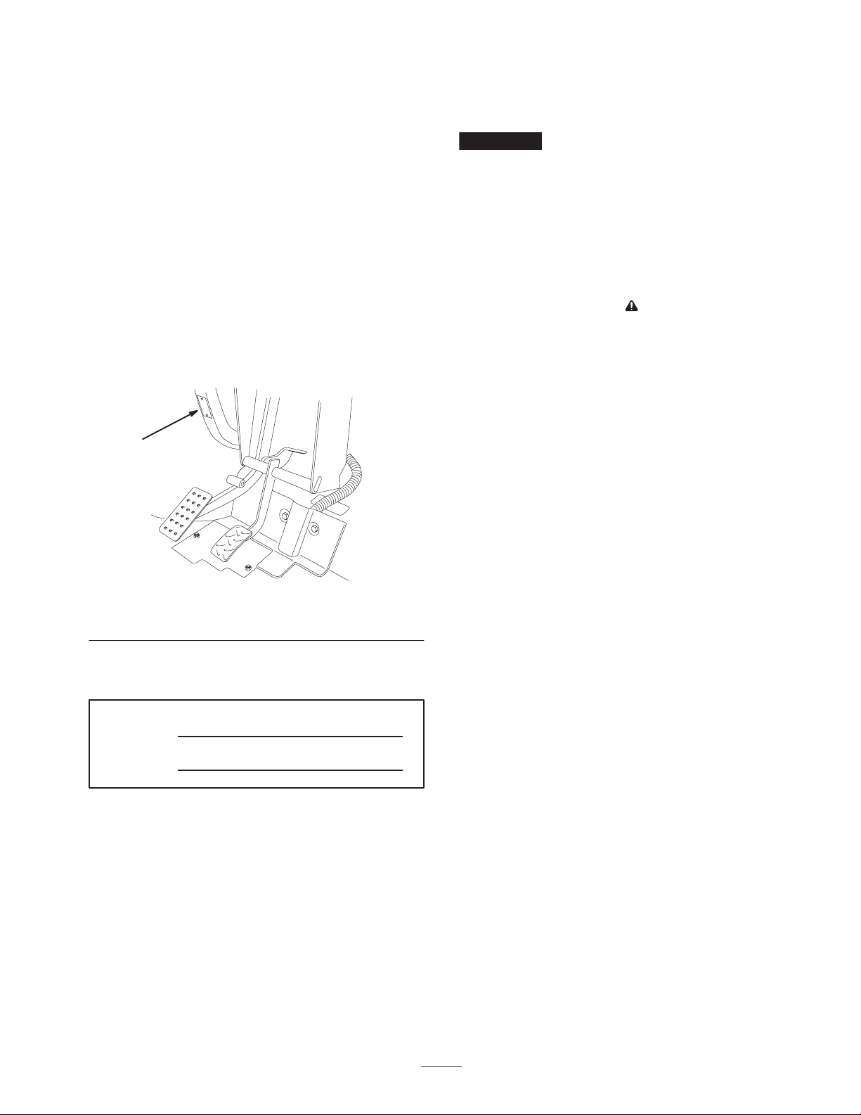
Controls
Accelerator Pedal
m–6203
1. Accelerator pedal
2. Brake pedal
1
Figure 13
3. Parking brake
Brake Pedal
The brake pedal is used to stop or slow the vehicle
(Fig. 13).
Caution
Brakes can become worn or can be misadjusted
resulting in personal injury.
If brake pedal travels to within 1 inch (25 mm) of
the vehicle floor board, the brakes must be
adjusted or repaired.
Parking Brake
The parking brake is a small plate at the top of the brake
pedal (Fig. 13). Whenever the engine is shut off, the
parking brake must be engaged to prevent accidental
movement of the vehicle. To engage the parking brake, step
on the brake pedal firmly and roll forward with the top of
your foot. To disengage, depress the accelerator pedal. If
the vehicle is parked on a steep grade, make sure the
parking brake is applied. Place blocks at the downhill side
of the wheels.
The accelerator pedal (Fig. 13) gives the operator the
ability to vary ground speed of the vehicle. Depressing the
pedal starts the engine. Depressing the pedal farther
increases ground speed. Releasing the pedal will slow the
vehicle and the engine will stop running. Maximum
forward speed is 14 mph (22 km/h).
17
Page 18

Choke Control
3
4
The choke control is located below and to the right of the
operator’s seat. To start a cold engine, pull the choke
control outward (Fig. 14). After the engine starts, regulate
the choke to keep the engine running smoothly. As soon as
possible, push the control in to the Off position. A warm
engine requires little or no choking.
1
2
m–5371
Figure 14
1. Choke 2. Gear shift selector
Gear Shift Selector
The gear shift selector has three positions: forward, reverse,
and neutral (Fig. 14). The engine will start and run in any
of the three positions.
Note: If the gear shift selector is in Reverse when the
ignition is turned on, a buzzer will sound to warn the
operator.
6
m-7365
2
1
5
Figure 15
1. Ignition switch
2. Hour meter
3. Light switch
4. Oil light
5. Power Point
6. Horn Button
Hour Meter
The hour meter (Fig. 15) indicates the total number of
hours the engine has run. The hour meter starts to function
whenever the accelerator is depressed.
Oil Light
The oil light warns the operator if the engine oil level drops
below a safe level (Fig. 15). If the light comes on and
remains lit, the oil level should be checked and oil added if
necessary; see Engine Oil, page 25.
Note: The oil light may flicker. This is normal and no
action needs to be taken.
Important Always stop the vehicle before changing
gears.
Ignition Switch
The ignition switch (Fig. 15), used to start and stop the
engine, has two positions: Off and On. Rotate the key
clockwise to the On position to allow operation. When the
vehicle is stopped, rotate the key counterclockwise to the
Off position. Remove the key from the ignition.
Light Switch
Toggle the switch to activate the headlights. Push to turn
the lights on (Fig. 15).
Power Point
Use the power point to power 12 volt optional electrical
accessories (Fig. 15).
Horn Button
Press the horn button to sound the horn (Fig. 15).
Fuel Gauge
The fuel gauge (Fig. 16) shows the amount of fuel in the
tank.
18
Page 19

1
Starting the Engine
1. Sit in the operator’s seat, insert the key into the ignition
switch, and rotate the key clockwise to the On position.
Note: If the gear shift selector is in Reverse, the buzzer will
sound to warn the operator.
Figure 16
1. Fuel gauge
Passenger Hand Holds
The passenger hand holds are located on the right side of
the dash panel and at the outside of each seat (Fig. 17).
1
Figure 17
1. Passenger hand hold 2. Hip restraint
2
m–4887
Pre-Starting Checks
Check the following items each time you begin using the
vehicle for the day:
• Check the tire pressure.
2. Move the gear shift selector to the desired position.
3. Slowly step on the accelerator pedal.
Note: The parking brake will automatically disengage
when the accelerator pedal is depressed.
Note: If the engine is cold, depress and hold the accelerator
pedal about half-way down, and pull the choke knob out to
the On position. Return the choke knob to Off after the
engine warms up.
Important Do not attempt to push or tow the vehicle to
get it started.
Stopping the Vehicle
To stop the vehicle, remove your foot from the accelerator
pedal and slowly depress the brake pedal.
Note: Stopping distance may vary depending on the vehicle
load and speed.
Parking the Vehicle
1. Engage the parking brake and rotate the ignition key to
Off.
2. Remove the key from the ignition switch to prevent
accidental starting.
Note: These tires are different than car tires; they
require less pressure to minimize turf compaction and
damage.
• Check all fluid levels and add the appropriate amount of
specified fluids, if any are found to be low.
• Check the brake pedal operation.
• Ensure that the lights are working.
• Turn the steering wheel to the left and right to check
steering response.
• Check for oil leaks, loose parts, and any other
noticeable malfunctions. Make sure the engine is off
and all moving parts have stopped before checking for
oil leaks, loose parts, and other malfunctions.
If any of the above items are not correct, notify your
mechanic or check with your supervisor before taking the
vehicle out for the day. Your supervisor may want you to
check other items on a daily basis, so ask what your
responsibilities are.
Cargo Bed
Raising the Bed
1. Slide the latch upward toward the top of the cutout in
the bed frame (Fig. 18).
1
m–4850
Figure 18
1. Latch
2. Lift up on the latch with one hand while raising the bed
with the other hand.
19
Page 20

3. Raise the bed to its full height; then lower it slightly to
engage the prop rod (Fig. 19).
New Vehicle Break-In
To provide proper performance and long vehicle life,
follow these guidelines for the first 100 operating hours:
1
m–4865
Figure 19
1. Prop rod
Lowering the Bed
1. Lift up the bed slightly with one hand while pressing
down on the prop rod.
2. Lower the bed until the latch engages.
3. To secure the bed tightly to the bed frame, move the
latch to the lower section of the cutout (Fig. 18).
Tailgate Latches
1. To open the tailgate latches, lift the latch handles up
(Fig. 20). The latches will spring out toward the center
of the tailgate. Slowly lower the tailgate.
Note: You may need to push the end of the tailgate in
(especially if there is a load against the tailgate) before the
latches will spring toward the center of the tailgate and
release.
1
• Check the fluid and engine oil levels regularly and be
alert for indications of overheating in any component of
the vehicle.
• After starting a cold engine, let it warm up for about
15 seconds before accelerating.
• Avoid hard braking situations for the first several hours
of new vehicle break-in operation. New brake linings
may not be at optimum performance until several hours
of use has caused the brakes to become burnished
(broken-in).
• Vary the vehicle speed during operation. Avoid fast
starts and quick stops.
• A break-in oil for engine is not required. Original
engine oil is the same type specified for regular oil
changes.
• Refer to the Maintenance section for any special low
hour checks.
• Check the front suspension positioning and adjust it if
necessary; refer to Adjusting the Front Suspension,
page 28.
Loading the Cargo Box
The capacity of the cargo box is 13 ft.3 (0.37 m3). The
amount (volume) of material that can be placed in the box
without exceeding the vehicle load ratings can vary greatly
depending on the density of the material. For example, a
level box of wet sand weighs 1500 lb. (680 kg), which
exceeds the load rating by 650 lb. (295 kg). But a level box
of wood weighs 650 lb. (295 kg), which is under the load
rating.
m–5334
Figure 20
1. Tailgate latch
2. To close the tailgate latches, lift the handles upward and
slide them toward the outside of the vehicle.
3. Push the latch handles downward to secure the latch and
tailgate.
See the table below for load volume limits with various
materials:
Material
Gravel
Dry
Wet
Sand
Dry
Wet
Wood 45 Full
Bark <45 Full
Earth, packed 100 2/3 full (approx.)
20
Density
(lb./ft.
95
120
90
120
Max. cargo box
capacity (on level
3
)
ground)
2/3 full (approx.)
1/2 full (approx.)
2/3 full
1/2 full
Page 21

Transporting the Vehicle
For moving the vehicle long distances, a trailer should be
used. Make sure that the vehicle is secured to the trailer.
Refer to Figures 21 and 22 for the location of the tie-down
points.
Caution
Loose seats may fall off of the vehicle and trailer
when transporting and land on another vehicle or
become an obstruction on the road.
Remove the seats or make sure that the seats are
securely fastened in the detents.
1
Figure 22
1. Towing tongue and tie down point
Towing a Trailer
The vehicle is capable of pulling trailers. Two types of tow
hitches are available for the vehicle, depending on your
application. Contact your Authorized Toro Distributor for
details.
1 1
Figure 21
1. Tie down points
Towing the Vehicle
In case of an emergency, the vehicle can be towed for a
short distance. However, we do not recommend this as a
standard procedure.
Warning
Towing at excessive speeds could cause a loss of
steering control, resulting in personal injury.
Never tow the vehicle faster than 5 mph (8 km/h).
Towing the vehicle is a two person job. If the machine must
be moved a considerable distance, transport it on a truck or
trailer; refer to Transporting the Vehicle, page 21.
1. Remove the drive belt; refer to Replacing the Drive
Belt, page 30, steps 1 and 2.
When hauling cargo or towing a trailer, do not overload
your vehicle or trailer. Overloading can cause poor
performance or damage to the brakes, axle, engine,
transaxle, steering, suspension, body structure, or tires.
Always load a trailer with 60% of the cargo weight in the
front of the trailer. This places approximately 10% of the
Gross Trailer Weight (GTW) on the tow hitch of the
vehicle.
The maximum cargo load shall not exceed 850 lb. (386 kg),
including the GTW and tongue weight. For example, if the
GTW = 400 lb. (181.5 kg) and tongue weight = 50 lb.
(23 kg), then the maximum cargo load = 400 lb. (181.5 kg)
To provide adequate braking and traction, always load the
cargo box when trailering. Do not exceed the GTW limits.
Avoid parking a vehicle with a trailer on a hill. If you must
park on a hill, engage the parking brake and block the
trailer tires.
2. Affix a tow line to the tongue on the front of the frame
(Fig. 22).
3. Put the vehicle in neutral and release the parking brake.
21
Page 22

Maintenance
Note: Determine the left and right sides of the machine from the normal operating position.
Recommended Maintenance Schedule
Important Refer to your engine operator’s manual for additional maintenance procedures.
Maintenance Service
Interval
After First Use
Every 8 Hours
After First 20 Hours
Every 50 Hours
Every 100 Hours
Maintenance Procedure
• Check the drive belt tension.
• Check the starter belt tension.
• Check the engine oil.
• Check the engine oil.
• Check the tire pressure.
• Change the engine oil.
• Check the front wheel toe-in at the proper ride height.
• Check the battery fluid level.
• Check the battery cable connections.
• Change the engine oil.
• Lubricate all grease fittings.
• Clean the engine cooling areas.
• Inspect the air cleaner filter.
• Inspect the brake and parking brake.
• Inspect the condition and wear of the tires.
• Torque the wheel lug nuts.
• Check the front suspension adjustment toe-in and ride height.
• Check the spark plug and replace it, if necessary.
• Check the operation of the Neutral gear shift position.
1
1
1
• Replace the air cleaner filter.
Every 200 Hours
Every 400 Hours or
Yearly
Every 800 Hours or
Yearly
1
Twice as often in special operating conditions; refer to Maintaining the Vehicle under Special Operating Conditions, page 24.
• Check the brake cable adjustments.
• Inspect the drive belt.
• Inspect and adjust the starter belt.
• Inspect the fuel lines.
• Clean and lubricate the primary drive clutch
• Complete all yearly maintenance procedures specified in the engine operator’s
manual.
• Replace the fuel filter.
• Change the transaxle oil.
22
Page 23

Daily Maintenance Checklist
Duplicate this page for routine use.
For the week of:
Maintenance Check Item
Check brake and parking brake
operation.
Check gear shift/neutral operation.
Check fuel level.
Check engine oil level.
Check transaxle oil level.
Inspect air filter.
Inspect engine cooling fins.
Check unusual engine noises.
Check unusual operating noises.
Check tire pressure.
Check fluid leaks.
Check instrument operation.
Check accelerator operation.
Check ride height and toe-in.
Lubricate all grease fittings.
1
Mon. Tues. Wed. Thurs. Fri. Sat. Sun.
Touch up damaged paint.
1
Lubricate the fittings immediately after every washing, regardless of the interval listed.
Notation for Areas of Concern
Inspection performed by:
Item Date Information
1
2
3
4
5
6
7
8
9
10
11
12
13
23
Page 24

Caution
If you leave the key in the ignition switch, someone could accidently start the engine and
seriously injure you or other bystanders.
Remove the key from the ignition and disconnect the wire from the spark plug before you do any
maintenance. Set the wire aside so that it does not accidentally contact the spark plug.
Warning
The bed must be raised to perform some routine
maintenance.
A raised bed can fall and injure persons that are
underneath it.
• Always use the prop rod to hold the bed up
before working under it.
• Remove any load material from the bed before
working under it.
Maintaining the Vehicle under
Special Operating Conditions
If the vehicle is subjected to any of the conditions listed
below, maintenance should be performed twice as
frequently.
• Desert operation
• Cold climate operation (below 50° F [10° C])
• Trailer towing
• Driving time typically less than 5 minutes
Danger
The vehicle may be unstable when using a jack. It
could slip off the jack, injuring anyone beneath it.
• Do not start the engine while the vehicle is on a
jack.
• Always remove the key from the ignition before
getting off of the vehicle.
• Block the tires when the vehicle is on a jack.
The jacking point at the front of the vehicle is on the front
of the frame behind the towing tongue (Fig. 23) The
jacking point at the rear of the vehicle is under the axle
tubes (Fig. 24).
1
• Frequent operation in dusty conditions
• Construction work
• After extended operation in mud, sand, water, or similar
dirty conditions, have your brakes inspected and
cleaned as soon as possible. This will prevent any
abrasive material from causing excessive wear.
• Under frequent heavy duty operating conditions,
lubricate all grease fittings and inspect air cleaner daily
to prevent excessive wear.
• Frequent periods with the engine idling in neutral (key
start models only)
Jacking the Vehicle
Whenever the engine is run for routine maintenance and/or
engine diagnostics, the rear wheels of the vehicle should be
1 inch (25 mm) off the ground with the rear axle supported
on jack stands.
Figure 23
1. Front jacking point
1 1
Figure 24
1. Rear jacking points
24
Page 25

Checking and Adjusting
Neutral
2
2
When performing routine maintenance and/or engine
diagnostics, the transaxle must be shifted into neutral
(Fig. 25). The vehicle has a neutral position on the shift
lever, which controls the neutral in the transaxle. The
following steps should be taken to make sure that the
neutral shift lever operates the transaxle neutral correctly:
1. Set the shift lever into the Neutral position.
2. Ensure that the neutral bracket is in the neutral position
(level) by turning the drive clutch (Fig. 25). The vehicle
should not roll back and forth. If it does, manually
move the neutral bracket to the neutral position.
2
1
4
3
Figure 26
1. Neutral bracket
2. Pull up
3. Cable boot
6. Start the engine and shift into Forward, Reverse, and
Neutral several times to ensure that the neutral bracket
is operating properly.
5
1
m–6184
4. Wrong, must tighten the
nut
5. Correct adjustment
Servicing the Engine Oil
Check the oil level before each use.
Change the oil after the first 20 operating hours and every
100 operating hours thereafter. Change the oil twice as
often in special operating conditions; refer to Maintaining
the Vehicle under Special Operating Conditions, page 24.
3
Figure 25
1. Neutral bracket 2. Locknuts
3. Tighten one of the locknuts (Fig. 25) just enough to take
the slack out of the shift cable.
Note: You must hold the threaded shaft below the bracket
to tighten the locknut on top.
4. Tighten the other locknut just enough to take the slack
out of the other shift cable.
5. Pull up on each shift cable an ensure that there is no gap
between the nut/washer and the neutral bracket
(Fig. 26). If there is a gap, tighten the nut.
Note: Change the oil more frequently when operating
conditions are extremely dusty or sandy.
Oil Type: Detergent oil (API service SG, SH, SJ, or higher)
Viscosity: See the table below.
USE THESE SAE VISCOSITY OILS
10W-30
5W-20, 5W-30
10W 20W 30W
–20 0 20 40 60 80 100
°
F
–30°–20 –10 0 10 20 30 40
C
Checking the Oil Level
To check the oil level, refer to Checking the Crankcase Oil,
page 15.
25
Page 26

Changing the Oil
1. Start the vehicle and let it run for a few minutes to
warm the oil.
2. Park the machine on a level surface, set the parking
brake, turn the ignition off, and remove the key.
3. Raise the bed and secure it with the prop rod.
4. Disconnect the spark plug wires and battery cables.
5. Remove the drain plug (Fig. 27) and let the oil flow into
a drain pan. When the oil has drained completely, install
the drain plug and torque it to 13 ft.-lb. (17.6 N⋅m).
1
Servicing the Air Cleaner
Check the air cleaner body for damage which could
possibly cause an air leak. Replace a damaged air cleaner
body.
Ensure the cover is sealing around the air cleaner body.
Air Cleaner Filter: Inspect after every 100 operating hours;
replace after every 200 hours or sooner if dirty or damaged.
Note: Service the air cleaner more frequently (every few
hours) if operating conditions are extremely dusty or sandy.
Removing the Filter Element
1. Park the machine on a level surface, set the parking
brake, turn the ignition off, and remove the key.
2. Raise the bed and secure it with the prop rod.
3. Release the latches securing the air cleaner cover to the
air cleaner body. Separate the cover from the body.
Clean the inside of the air cleaner cover (Fig. 28).
4. Gently slide the filter out of the air cleaner body to
reduce the amount of dust dislodged (Fig. 28). Avoid
knocking the filter against the air cleaner body.
Figure 27
1. Engine oil drain plug
Note: Dispose of the used oil at a certified recycling center.
6. Clean around the oil dipstick and unscrew the cap.
7. Slowly pour approximately 80% of the specified
amount of oil into the filler tube and check the oil level;
refer to Checking the Crankcase Oil, page 15. Slowly
add oil to bring the level to the “F” mark on the
dipstick.
8. Install the dipstick.
Cleaning the Engine Cooling
Areas
Clean the rotating screen, cooling fins, and external
surfaces of the engine every 100 operating hours or more
often under extremely dusty and dirty conditions.
Important Operating the engine with a blocked
rotating screen, dirty or plugged cooling fins, or cooling
shrouds removed will cause engine damage due to
overheating.
Important Never clean the engine with pressurized
water because water could contaminate the fuel system.
3
2
Figure 28
1. Air cleaner latches
2. Cover
5. Inspect the filter and discard it if it is damaged.
3. Filter
1
Cleaning the Filter Element
Important Do not wash or reuse a damaged filter.
1. Washing method:
A. Prepare a solution of filter cleaner and water and
soak the filter element for about 15 minutes. Refer
to the directions on the filter cleaner carton for
complete information.
26
Page 27

B. After soaking the filter for 15 minutes, rinse it with
clear water. Rinse the filter from the clean side to
the dirty side.
Important To prevent damage to the filter element,
the maximum water pressure must not exceed 40 psi.
(276 kPa)
C. Dry the filter element using warm, flowing air at
160°F (71°C) maximum, or allow the element to
air-dry.
Important Do not use a light bulb to dry the filter
element because damage could result.
2. Compressed air method:
A. Blow compressed air from the inside to the outside
of the dry filter element. Keep the air hose nozzle at
least 2 inches (51 mm) from the filter and move the
nozzle up and down while rotating the filter
element.
Important To prevent damage to the filter element,
do not exceed 100 psi (689 kPa) air pressure.
B. Inspect the filter element for holes and tears by
looking through the filter toward a bright light.
1. Wipe the grease fitting clean so foreign matter cannot
be forced into the bearing or bushing.
2. Pump grease into the bearing or bushing.
3. Wipe off excess grease.
m–5320
Figure 29
Installing the Filter Element
Important To prevent engine damage, always operate
the engine with the complete air cleaner assembly installed.
1. Inspect the new filter for shipping damage. Check the
sealing end of the filter.
Important Do not install a damaged filter.
2. Insert the new filter into air cleaner body. Ensure the
filter is sealed properly by applying pressure to the
outer rim of the filter when installing it. Do not press on
the flexible center of the filter.
3. Install the cover and secure the latches.
Greasing the Machine
Lubricate all of the bearings and bushings every 100 hours
or once a year, whichever occurs first. Grease them more
frequently when using the vehicle for heavy-duty
operations.
Grease Type: Number 2 General Purpose Lithium Base
Grease
Where to Add Grease
The grease fitting locations are at the four tie rod ends
(Fig. 29) and the two king pins (Fig. 30).
m–5324
Figure 30
Servicing the Brakes
Inspecting the Brakes
Brakes are a critical safety component of the vehicle. As
with all safety components, they should be closely
inspected at regular intervals to ensure optimum
performance and safety. The following inspections should
be done every 100 hours:
• Inspect the brake shoes for wear or damage. If the
lining (brake pad) thickness is less than 1/16 inch
(1.6 mm), the brake shoes should be replaced.
• Inspect the backing plate and other components for
signs of excessive wear or deformation. If any
deformation is found, the appropriate components must
be replaced.
Adjusting the Brake Pedal
Adjust the brake if the parking brake does not hold, the
brake pedal travel is excessive, or braking power is not
sufficient when the brake pedal is depressed. Check the
adjustment every 200 hours.
1. Turn the ignition off and remove the key.
27
Page 28

2. Check the brake cables at the brake equalizer (located
under the dash) and determine approximately how far
up the brake rod the equalizer needs to travel so that
there is no slack in the cables (Fig. 31).
Check the wheels to ensure that they are mounted securely.
Torque the center bolts on the front wheels to 135–165 ft-lb
(183–224 N⋅m) and the front and rear lug nuts to
45–65 ft-lb (61–88 N⋅m).
1
2
3
4
6
7
5
7
m–6288
Figure 31
1. Clevis pin
2. Brake lever
3. Brake rod clevis
4. Brake rod
5. Brake equalizer
6. Spring
7. Brake cable
3. Remove the hairpin cotter and clevis pins securing the
brake rod clevis (Fig. 31).
4. Disconnect the spring from the end of the brake rod
(Fig. 31).
Adjusting the Front
Suspension
The ride height of each side of the vehicle can be adjusted
separately. The ride height should be 8-3/4 to 9-1/2 inches
(22.2 to 24 cm) with the following parameters:
• The tire pressure should be at 12 psi (83 kPa).
• The vehicle should be driven back and forth a few times
to relax the A-arms.
• Measure the ride height with the wheels facing straight
ahead and a 175–225 lb. (79–102 kg) operator in the
driver’s seat.
Note: The driver should drive up to the measurement
area and stay seated in the vehicle while the
measurement is being taken.
• Measure the ride height on a flat surface, from the
bottom of the front tongue to the ground.
1. Jack the front end of the vehicle off of the ground; refer
to Jacking the Vehicle, page 24.
2. Remove the travel limiting bolt (Fig. 32).
3. Loosen the centering bolts in the front A-arm (Fig. 32).
4. Remove the ride height adjustment bolt (Fig. 32).
5. Press the brake pedal down fully to raise the brake
lever.
6. Thread the brake rod in or out of the brake equalizer as
needed to remove the slack from the brake cables
(Fig. 31). Do not overtighten the cables.
7. Install the spring into the hole in the brake rod (Fig. 31).
8. Connect the clevis on the brake rod to the brake lever
using the clevis pin and hairpin cotter removed
previously (Fig. 31).
9. Ensure that there is some free play in the brake pedal
before the brake engages. If not, repeat this procedure
until there is.
Inspecting the Tires
Check the tire condition at least every 100 hours of
operation. Operating accidents, such as hitting curbs, can
damage a tire or rim and also disrupt wheel alignment, so
inspect tire condition after an accident.
2
3
2
1
Figure 32
1. Travel limiting bolt
2. Centering bolt
3. Ride height adjustment
bolt
5. Rotate the front A-arm to the desired position (refer to
the note below) and replace the ride height adjustment
bolt (Fig. 32).
28
Page 29

Note: The A-arms are made with rubber and have different
spring rates. Because of the different spring rates, the
A-arms come adjusted from the factory based on that
spring rate. Generally the adjustment bolts will be installed
in hole number 2, 3, or 4 (Fig. 33) and it may be different
from the left side (driver side) to the right side (passenger
side). If the A-arms look like they are sagging, then they
should be adjusted to the next higher number (Fig. 33).
Each hole equals about 3/4 inch (19 mm) of adjustment at
the wheel. You will also need to do this if you are adding
heavy attachments or carrying heavy loads often.
1
m–5640
Figure 33
1. Left-hand A-arm
• The ride height should be correct before setting the
toe-in; refer to Adjusting the Front Suspension, page 28.
• The vehicle should be driven back and forth a few times
to relax the A-arms.
• Measure the toe-in with the wheels facing straight
ahead and a 175–225 lb. (79–102 kg) operator in the
driver’s seat.
Note: The driver should drive up to the measurement
area and stay seated in the vehicle while the
measurement is being taken.
If the vehicle will be run with medium to heavy loads most
of the time, set the toe-in on the high side of the
recommended amount. If it is going to be run with a light
load most of the time, set the toe-in on the low side of the
recommended amount.
1. Ensure that the front suspension is adjusted properly;
refer to Adjusting the Front Suspension, page 28.
Adjust if necessary.
2. Measure the distance between both of the front tires at
the axle height at both the front and rear of the front
tires (Fig. 34). A fixture or alignment gauge is needed
for the rear measurement of the front tires at axle
height. Use the same fixture or alignment gauge to
accurately measure the front of the front tires at axle
height (Fig. 34).
6
1
6. Torque the ride height adjustment bolt to 135–165 ft.-lb.
(183–224 N⋅m).
7. Replace the travel limiting bolt (Fig. 32).
Note: The vehicle may need to be lowered to the ground on
that side to install the bolt.
8. Tighten and torque the centering bolts to
240–290 ft.-lbs. (325–393 N⋅m).
9. Check the ride height at the front tongue per the
dimensions and parameters given at the beginning of
this procedure.
Adjusting Front Wheel Toe-In
Check the front wheel toe-in after every 100 operating
hours, or annually, whichever occurs first.
The toe-in should be 1/8–5/8 inch (3–16 mm) with the
following parameters:
• The tire pressure should be at 12 psi (83 kPa).
5
4
2
3
52 inches
(132 cm)
5
m–5639
Figure 34
1. Tire center line—back
2. Tire center line—front
3. Axle center line
4. Fixture
5. Axle center line distance
6. 6 inches (15 cm) ruler
3. If the measurement does not fall within the specified
range (refer to the dimensions and parameters at the
beginning of this procedure),
loosen the jam nuts at
both ends of the tie rods (Fig. 35).
4. Rotate both tie rods to move the front of the tire inward
or outward.
29
Page 30

1
2
1
m–5320
Figure 35
1. Jam nut 2. Tie rod
5. Tighten the tie rod jam nuts when the adjustment is
correct.
6. Ensure that there is full travel of the steering wheel in
both directions.
Servicing the Drive Belt
Checking the Drive Belt
Check the condition and tension of the drive belt after the
first day of operation and every 200 operating hours
thereafter.
1. Park the machine on a level surface, shift into Neutral,
set the parking brake, turn the ignition off, and remove
the key.
3. To replace the belt, reverse the procedure.
Adjusting the Starter Generator
Belt
Check the tension of the starter generator belt after the first
day of operation and every 200 operating hours thereafter.
1. Park the machine on a level surface, set the parking
brake, turn the ignition off, and remove the key.
2. Loosen the starter generator pivot bolt (Fig. 37).
2
1
Figure 37
1. Generator pivot bolt 2. Adjusting carriage bolt
2. Raise the bed and secure it with the prop rod.
3. Rotate and inspect the belt (Fig. 36) for excessive wear
or damage. Replace the belt if necessary.
1
3
1. Drive belt
2. Primary clutch
2
Figure 36
3. Secondary clutch
Replacing the Drive Belt
1. Rotate and route the belt over the secondary clutch
(Fig. 36).
3. Wedge a pry bar between the engine mount and starter.
Loosen the nut on the adjusting carriage bolt (Fig. 37).
4. Tilt the starter in the slot until the belt flexes 1/4 inch
(6 mm) with 10 lb. (44.5 N) of force.
5. Tighten the carriage bolt nut and remove the pry bar.
Tighten the starter generator pivot bolt (Fig. 37).
Maintaining the Primary Drive
Clutch
After every 400 operating hours or yearly, clean and
lubricate the clutch as follows:
1. Raise and latch the cargo box.
2. Stop the engine, remove the key, and set the parking
brake.
2. Remove the belt from the primary clutch (Fig. 36).
30
Page 31

3. Remove the 3 bolts securing the cover to the clutch and
remove the cover (Fig. 38).
Replacing Fuel Filter
Replace the fuel filter after every 800 operating hours or
yearly, whichever occurs first.
1. Raise the bed and support it with the prop rod.
2. Place a clean container under the fuel filter.
1
2
m–6988
Figure 38
1. Cover 2. Bolts
4. Thoroughly clean the inside of the cover and the inner
workings of the clutch using compressed air.
Caution
The dust in the clutch will become airborne and
could damage your eyes or you could inhale it
causing breathing difficulties.
Wear safety goggles and a dust mask or other eye
and respiratory protection when performing this
procedure.
5. Lubricate the moving parts in the areas circled in Figure
39 using Toro Dry Lubricant Spray, available through
your Authorized Toro Dealer or Distributor.
3. Remove the clamps securing the fuel filter to the fuel
lines.
1
m–5322
Figure 40
1. Fuel filter
4. Install the replacement fuel filter to the fuel lines with
the clamps previously removed. Mount the filter so that
the arrow points toward the carburetor.
Servicing the Spark Plug
Check the spark plug after every 100 operating hours or
yearly, whichever occurs first. Replace if necessary.
Type: Champion RN14YC (or equivalent)
Air Gap: 0.030 inch (0.762 mm)
m–6989
Figure 39
6. Install the clutch cover and secure it with the 3 bolts
removed previously.
Servicing the Fuel System
Fuel Lines and Connections
Check the fuel lines and connections every 400 operating
hours or yearly, whichever occurs first. Inspect them for
deterioration, damage, or loose connections.
Checking and Replacing the Spark Plug
Note: The spark plug usually lasts a long time; however,
the plug should be removed and checked whenever the
engine malfunctions.
1. Clean the area around the spark plugs so that foreign
matter cannot fall into the cylinder when the spark plug
is removed.
2. Pull the wires off of the spark plugs and remove the
plugs from the cylinder head.
3. Check the condition of the side electrode, center
electrode, and center electrode insulator to ensure that
there is no damage.
Important A cracked, fouled, dirty, or malfunctioning
spark plug must be replaced. Do not sand-blast, scrape, or
clean electrodes by using a wire brush because grit may
eventually release from the plug and fall into the cylinder.
The result is usually a damaged engine.
4. Set the air gap between the center and side of the
electrodes at 0.030 inch (0.762 mm) (Fig. 41). Install
the correctly gapped spark plug and tighten the plug to
14 ft.-lb. (20 N⋅m).
31
Page 32

5. Install the spark plug wires.
1
0.030 inch
(0.762 mm)
Figure 41
Changing the Transaxle Fluid
Change the transaxle fluid every 800 operating hours or
yearly, whichever occurs first.
1. Position the vehicle on a level surface, set the parking
brake, turn the ignition off, and remove the key.
2. Remove the drain plug from the right side of the
reservoir (Fig. 42) and let the fluid flow into a drain
pan. Install and tighten the plug when the fluid stops
draining.
Note: Dispose of the used oil at a certified recycling center.
1
Figure 43
1. Oil fill
4. Start the engine and operate it to fill the system.
Recheck the oil level and replenish it, if required.
Replacing the Fuses
There are 3 fuses in the electrical system. They are located
beneath the bed in a box on the right hand side of the frame
(Fig. 44).
Ignition System
Lights 10 amp.
Power Point 10 amp.
(15 amp. max.)
10 amp.
1
2
m–4849
Figure 42
1. Drain plug 2. Level indicator hole
3. Fill the reservoir (Fig. 43) with approximately 1-1/2 qt.
(1.4 liters) of SAE 10W30 motor oil or until the oil
level is at the bottom of the level indicator hole
(Fig. 42).
2
m–7778
1. Ignition system
2. Lights
3
Figure 44
3. Power point
Replacing the Headlights
Specification: GE Headlight #H7610
1. Set the parking brake, turn the ignition off, and remove
the key.
2. Reach beneath the dash and push the headlight out of
the hood.
32
Page 33

3. Remove the screws attaching the wire harness to the
headlight.
4. Remove the rubber seal from around the headlight
(Fig. 45). Discard the headlight.
of four parts water and one part baking soda. Apply a light
coating of grease to the battery terminals to prevent
corrosion.
Voltage: 12 volt with 280 cold cranking Amps @ 0° F
(–18° C).
Removing the Battery
1. Position the vehicle on a level surface, set the parking
brake, turn the ignition off, and remove the key.
3
2
4
1. Rubber seal
2. Inside notch—align with
the notch on the headlight
5. Align the notch on the inside of the seal with the notch
on the new headlight (Fig. 45). Slide the seal onto the
headlight until the seal is firmly in place.
6. Attach the headlight to the wire harness using the
previously removed screws.
7. Align the notch on the outside of the seal with the notch
in the hood. Push the headlight and seal into the hood
until it is firmly in place.
Note: Applying soapy water to the outside of the seal may
aid in sliding the seal into the hood.
1
Figure 45
3. Outside notch—align with
notch in hood
4. Headlight
Servicing the Battery
Warning
CALIFORNIA
Proposition 65 Warning
Battery posts, terminals, and related accessories
contain lead and lead compounds, chemicals
known to the State of California to cause cancer
and reproductive harm. Wash hands after
handling.
2. Raise the bed and secure it with the prop rod.
3. Remove the battery hold-down.
4. Disconnect the negative (black) ground cable from the
battery post.
Warning
Incorrect battery cable routing could damage the
vehicle and cables, causing sparks. Sparks can
cause the battery gasses to explode, resulting in
personal injury.
• Always disconnect the negative (black) battery
cable before disconnecting the positive (red)
cable.
• Always reconnect the positive (red) battery cable
before reconnecting the negative (black) cable.
• Always keep the battery strap in place to protect
and secure the battery.
Warning
Battery terminals or metal tools could short
against metal vehicle components, causing sparks.
Sparks can cause the battery gasses to explode,
resulting in personal injury.
• When removing or installing the battery, do not
allow the battery terminals to touch any metal
parts of the vehicle.
• Do not allow metal tools to short between the
battery terminals and metal parts of the vehicle.
5. Disconnect the positive (red) cable from the battery
post.
6. Remove the battery from the chassis.
Important Do not jump start the vehicle.
Always keep the battery clean and fully charged. Use a
paper towel to clean the battery and battery box. If the
battery terminals are corroded, clean them with a solution
Installing the Battery
1. Set the battery on the battery base so the battery posts
are toward the rear of the vehicle.
33
Page 34

2. Connect the positive (red) cable to the positive (+)
battery post and the negative (black) cable to the
negative (–) battery post using the bolts and wing nuts.
Slide the rubber boot over the positive battery post.
3. Replace the battery hold-down to secure the battery to
the base.
1. Remove the battery from the chassis; refer to Removing
the Battery, page 33.
2. Connect a 3 to 4 amp battery charger to the battery
posts. Charge the battery at a rate of 3 to 4 amperes for
4 to 8 hours (12 volts). Do not overcharge the battery.
Important Always keep the battery hold-down in place
to protect and secure the battery.
Checking the Electrolyte Level
Check the electrolyte level every 50 operating hours or, if
the machine is in storage, every 30 days.
1. Raise the bed and secure it with the prop rod.
2. Remove the filler caps. If the electrolyte is not up to the
fill line, add the required amount of distilled water;
refer to Adding Water to the Battery, page 34.
Danger
Battery electrolyte contains sulfuric acid which is a
deadly poison and causes severe burns.
• Do not drink electrolyte or allow it to contact
your skin, eyes or clothing. Wear safety glasses
to shield your eyes and rubber gloves to protect
your hands.
• Fill the battery where clean water is always
available for flushing the skin.
Warning
Charging the battery produces gasses that can
explode.
Never smoke near the battery and keep sparks and
flames away from battery.
3. Install the battery in the chassis; refer to Installing the
Battery, page 33.
Storing the Battery
If the machine will be stored for more than 30 days, remove
the battery and charge it fully. Either store it on the shelf or
on the machine. Leave the cables disconnected if it is stored
on the machine. Store the battery in a cool atmosphere to
avoid quick deterioration of the charge in the battery. To
prevent the battery from freezing, make sure it is fully
charged.
Washing the Vehicle
The vehicle should be washed as needed. Use water alone
or with a mild detergent. A rag may be used, however the
hood will loose some of its luster.
Adding Water to the Battery
The best time to add distilled water to the battery is just
before you operate the machine. This lets the water mix
thoroughly with the electrolyte solution.
1. Clean the top of the battery with a paper towel.
2. Remove the filler caps from the battery and slowly fill
each cell with distilled water until the level is up to the
fill line. Replace the filler caps.
Important Do not overfill the battery. Electrolyte will
overflow onto other parts of the vehicle and severe
corrosion and deterioration will result.
Charging the Battery
Important Always keep the battery fully charged
(1.260 specific gravity). This is especially important to
prevent battery damage when the temperature is below
32°F (0°C).
Important Pressurized water is not recommended when
washing the machine. It may damage the electrical system,
loosen important decals, or wash away necessary grease at
friction points. Avoid excessive use of water, especially
near the control panel, engine, and battery.
34
Page 35

Schematics
Electrical Schematic
35
m-7375
Page 36

The Toro General Commercial Products Warranty
A Two-Year Limited Warranty
Conditions and Products Covered
The Toro Company and its affiliate, Toro Warranty Company,
pursuant to an agreement between them, jointly warrant your Toro
Commercial Product (“Product”) to be free from defects in
materials or workmanship for two years or 1500 operational
hours*, whichever occurs first. Where a warrantable condition
exists, we will repair the Product at no cost to you including
diagnosis, labor, parts, and transportation. This warranty begins
on the date the Product is delivered to the original retail purchaser.
* Product equipped with hour meter
Instructions for Obtaining Warranty Service
You are responsible for notifying the Commercial Products
Distributor or Authorized Commercial Products Dealer from whom
you purchased the Product as soon as you believe a warrantable
condition exists.
If you need help locating a Commercial Products Distributor or
Authorized Dealer, or if you have questions regarding your
warranty rights or responsibilities, you may contact us at:
Toro Commercial Products Service Department
Toro Warranty Company
8111 Lyndale Avenue South
Bloomington, MN 55420-1196
952-888-8801 or 800-982-2740
E-mail: commercial.service@toro.com
Owner Responsibilities
As the Product owner, you are responsible for required maintenance and adjustments stated in your operator’s manual. Failure
to perform required maintenance and adjustments can be grounds
for disallowing a warranty claim.
Items and Conditions Not Covered
Not all product failures or malfunctions that occur during the
warranty period are defects in materials or workmanship. This
express warranty does not cover the following:
• Product failures which result from the use of non-Toro
replacement parts, or from installation and use of add-on,
modified, or unapproved accessories
• Product failures which result from failure to perform required
maintenance and/or adjustments
• Product failures which result from operating the Product in an
abusive, negligent or reckless manner
• Parts subject to consumption through use unless found to be
defective. Examples of parts which are consumed, or used up,
during normal Product operation include, but are not limited to,
blades, reels, bedknives, tines, spark plugs, castor wheels,
tires, filters, belts, etc.
• Failures caused by outside influence. Items considered to be
outside influence include, but are not limited to, weather,
storage practices, contamination, use of unapproved coolants,
lubricants, additives, or chemicals, etc.
• Normal “wear and tear” items. Normal “wear and tear” includes,
but is not limited to, damage to seats due to wear or abrasion,
worn painted surfaces, scratched decals or windows, etc.
Parts
Parts scheduled for replacement as required maintenance are
warranted for the period of time up to the scheduled replacement
time for that part.
Parts replaced under this warranty become the property of Toro.
Toro will make the final decision whether to repair any existing part
or assembly or replace it. Toro may use factory remanufactured
parts rather than new parts for some warranty repairs.
General Conditions
Repair by an Authorized Toro Distributor or Dealer is your sole
remedy under this warranty.
Neither The Toro Company nor Toro Warranty Company is
liable for indirect, incidental or consequential damages in
connection with the use of the Toro Products covered by this
warranty, including any cost or expense of providing substitute equipment or service during reasonable periods of
malfunction or non-use pending completion of repairs under
this warranty. Except for the Emissions warranty referenced
below, if applicable, there is no other express warranty. All
implied warranties of merchantability and fitness for use are
limited to the duration of this express warranty.
Some states do not allow exclusions of incidental or consequential
damages, or limitations on how long an implied warranty lasts, so
the above exclusions and limitations may not apply to you.
This warranty gives you specific legal rights, and you may also
have other rights which vary from state to state.
Note regarding engine warranty: The Emissions Control System
on your Product may be covered by a separate warranty meeting
requirements established by the U.S. Environmental Protection
Agency (EPA) and/or the California Air Resources Board (CARB).
The hour limitations set forth above do not apply to the Emissions
Control System Warranty. Refer to the Engine Emission Control
Warranty Statement printed in your operator’s manual or contained in the engine manufacturer’s documentation for details.
Countries Other than the United States or Canada
Customers who have purchased Toro products exported from the United States or Canada should contact their Toro Distributor (Dealer)
to obtain guarantee policies for your country, province, or state. If for any reason you are dissatisfied with your Distributor’s service or
have difficulty obtaining guarantee information, contact the Toro importer. If all other remedies fail, you may contact us at Toro Warranty
Company.
Part No. 374-0031 Rev. A
 Loading...