

Page 1
FormNo.3416-503RevC
Workman
®
GTXElectricUtility
Vehicle
ModelNo.07041—SerialNo.401061654andUp
ModelNo.07043—SerialNo.401160341andUp
ModelNo.07131TC—SerialNo.400000000andUp
ModelNo.07139—SerialNo.400000000andUp
ModelNo.07139TC—SerialNo.400000000andUp
Registeratwww.T oro.com.
OriginalInstructions(EN)
*3416-503*C
Page 2
WARNING
CALIFORNIA
Proposition65Warning
Thisproductcontainsachemical
orchemicalsknowntotheStateof
Californiatocausecancer,birthdefects,
orreproductiveharm.
Useofthisproductmaycauseexposure
tochemicalsknowntotheStateof
Californiatocausecancer,birthdefects,
orotherreproductiveharm.
ThisproductcomplieswithallrelevantEuropean
directives;fordetails,pleaseseetheseparateproduct
specicDeclarationofConformity(DOC)sheet.
Introduction
ModelNo.
SerialNo.
Thismanualidentiespotentialhazardsandhas
safetymessagesidentiedbythesafety-alertsymbol
(Figure2),whichsignalsahazardthatmaycause
seriousinjuryordeathifyoudonotfollowthe
recommendedprecautions.
g000502
Figure2
Safety-alertsymbol
Thismanualuses2wordstohighlightinformation.
Importantcallsattentiontospecialmechanical
informationandNoteemphasizesgeneralinformation
worthyofspecialattention.
Readthisinformationcarefullytolearnhowtooperate
andmaintainyourproductproperlyandtoavoid
injuryandproductdamage.Youareresponsiblefor
operatingtheproductproperlyandsafely .
YoumaycontactT orodirectlyatwww.Toro.comfor
productandaccessoryinformation,helpndinga
dealer,ortoregisteryourproduct.
Wheneveryouneedservice,genuineToroparts,or
additionalinformation,contactanAuthorizedService
DealerorToroCustomerServiceandhavethemodel
andserialnumbersofyourproductready.Figure1
identiesthelocationofthemodelandserialnumbers
ontheproduct.Writethenumbersinthespace
provided.
BottomofSeatAssemblyShown
1.Modelandserial-numberlocation
©2017—TheToro®Company
8111LyndaleAvenueSouth
Bloomington,MN55420
Figure1
g034086
Contactusatwww.Toro.com.
2
PrintedintheUSA
AllRightsReserved
Page 3

Contents
Safety.......................................................................4
GeneralSafety...................................................4
BeforeOperationSafety.....................................4
DuringOperationSafety.....................................4
Multi-PassengerSafety......................................5
SlopeSafety.......................................................5
LoadingandDumpingSafety..............................6
AfterOperationSafety........................................6
SafetyandInstructionalDecals..........................7
Setup......................................................................10
1InstallingtheSteeringWheel(International
ModelsOnly).................................................10
2CheckingtheFluidLevelsandTire
Pressure.......................................................10
3BurnishingtheBrakes.....................................11
4ReadingtheManualandViewingthe
SetupMaterial................................................11
ProductOverview...................................................12
Controls...........................................................13
Specications..................................................16
Attachments/Accessories.................................16
Operation................................................................17
ThinkSafetyFirst..............................................17
OperatingtheCargoBed..................................17
UsingtheRearCargoBedAccessory
Mount............................................................20
PerformingDailyMaintenance..........................20
CheckingtheTirePressure...............................20
UnderstandingandUsingtheBattery
System..........................................................21
StoppingtheMachine.......................................23
BreakinginaNewMachine..............................23
LoadingtheCargoBed.....................................23
TransportingtheMachine.................................24
TowingtheMachine..........................................25
TowingaTrailer................................................25
Maintenance...........................................................26
RecommendedMaintenanceSchedule(s)...........26
DailyMaintenanceChecklist.............................27
MaintainingtheMachineunderSpecial
OperatingConditions....................................27
Pre-MaintenanceProcedures..............................28
MaintenanceSafety..........................................28
PreparingtheMachineforMaintenance............28
LiftingtheMachine...........................................29
AccessingtheHood..........................................30
RaisingandLoweringtheSeat
Assembly......................................................30
RemovingtheSeatAssembly...........................31
InstallingtheSeatAssembly.............................31
Lubrication..........................................................31
GreasingtheMachine.......................................31
GreasingtheFrontWheelBearings..................32
ElectricalSystemMaintenance...........................35
ElectricalSystemSafety...................................35
BatterySafety...................................................35
MaintainingtheBatteries..................................36
ReplacingtheFuses.........................................40
MaintainingtheHeadlights...............................40
DriveSystemMaintenance..................................42
MaintainingtheTires........................................42
AdjustingtheFrontWheelAlignment................42
CheckingtheTransaxle-FluidLevel..................43
ChangingtheTransaxleFluid...........................43
BrakeMaintenance.............................................44
CheckingtheParkingBrake.............................44
AdjustingtheParkingBrake..............................44
CheckingtheBrake-FluidLevel........................44
InspectingtheBrakes.......................................45
ReplacingtheServiceandParking-Brake
Pads..............................................................45
ChangingtheBrakeFluid.................................45
ChassisMaintenance...........................................46
AdjustingtheCargo-BedLatches.....................46
Cleaning..............................................................46
WashingtheMachine.......................................46
Storage...................................................................47
BatteryStorage................................................47
Troubleshooting......................................................48
3
Page 4

Safety
motorquickly.
•Knowhowtostopthemachineandshutoffthe
Improperuseormaintenancebytheoperatoror
ownercanresultininjury.T oreducethepotential
forinjury,complywiththesesafetyinstructions
andalwayspayattentiontothesafety-alert
symbol(Figure2),whichmeansCaution,Warning,
orDanger—personalsafetyinstruction.Failureto
complywiththeinstructionmayresultinpersonal
injuryordeath.
ThismachinemeetstherequirementsofSAEJ2258.
GeneralSafety
Thisproductiscapableofcausingpersonalinjury.
Alwaysfollowallsafetyinstructionstoavoidserious
personalinjury.
Usingthisproductforpurposesotherthanitsintended
usecouldprovedangeroustoyouandbystanders.
•Readandunderstandthecontentsofthis
Operator’sManualbeforeyoustarttheengine.
Ensurethateveryoneusingthisproductknows
howtouseitandunderstandsthewarnings.
•Donotputyourhandsorfeetnearmoving
componentsofthemachine.
•Donotoperatethemachinewithoutallguards
andothersafetyprotectivedevicesinplaceand
workingonthemachine.
•Keepthemachineasafedistanceawayfrom
bystanderswhileitismoving.
•Keepchildrenoutoftheoperatingarea.Never
allowchildrentooperatethemachine.
•Stopthemachineandshutofftheenginebefore
servicing,fueling,oruncloggingthemachine.
Improperlyusingormaintainingthismachinecan
resultininjury.Toreducethepotentialforinjury,
complywiththesesafetyinstructionsandalwayspay
attentiontothesafety-alertsymbol,whichmeans
Caution,Warning,orDanger—personalsafety
instruction.Failuretocomplywiththeseinstructions
mayresultinpersonalinjuryordeath.
Youcanndadditionalsafetyinformationwhere
neededthroughoutthismanual.
•Checkthatallsafetydevicesanddecalsarein
place.Repairorreplaceallsafetydevicesand
replaceallillegibleormissingdecals.Donot
operatethemachineunlesstheyarepresentand
functioningproperly.
DuringOperationSafety
•Theowner/operatorcanpreventandisresponsible
foraccidentsthatmaycausepersonalinjuryor
propertydamage.
•Passengersshouldsitinthedesignatedseating
positionsonly.Donotcarrypassengersinthe
cargobed.Keepbystandersandpetsawayfrom
themachineduringoperation.
•Wearappropriateclothing,includingeye
protection;longpants;substantial,slip-resistant
footwear;andhearingprotection.Tiebacklong
hairanddonotwearjewelry.
•Donotoperatethemachinewhileill,tired,or
undertheinuenceofalcoholordrugs.
•Operatethemachineoutdoorsorina
well-ventilatedareaonly.
•Donotexceedthemaximumgrossvehicleweight
(GVW)ofthemachine.
•Useextracautionwhenoperatingthemachine
withaheavyloadinthecargobed.Theheavier
theload,themoredifcultitistoturnorstop.
•Carryingoversizedloadsinthecargobedreduces
thestabilityofthemachine.
•Carryingmaterialthatcannotbeboundtothe
machine,suchasalargetankofliquid,adversely
affectsthesteering,braking,andstabilityofthe
machine.
•Beforeyoustartthemotor,ensurethatthe
transmissionisinneutral,theparkingbrakeis
engaged,andyouareintheoperatingposition.
•Youandyourpassengersshouldremainseated
wheneverthemachineismoving.Keepyour
handsonthesteeringwheel;yourpassengers
shouldusethehandholdsprovided.Keepyour
armsandlegswithinthemachinebodyatalltimes.
BeforeOperationSafety
•Neverallowchildrenoruntrainedpeopleto
operateorservicethemachine.Localregulations
mayrestricttheageoftheoperator.Theowner
isresponsiblefortrainingalloperatorsand
mechanics.
•Becomefamiliarwiththesafeoperationofthe
equipment,operatorcontrols,andsafetysigns.
•Operatethemachineonlyingoodvisibility.
Watchforholes,ruts,bumps,rocks,orother
hiddenobjects.Uneventerraincouldoverturnthe
machine.Tallgrasscanhideobstacles.Usecare
whenapproachingblindcorners,shrubs,trees,or
otherobjectsthatmayobscureyourvision.
•Alwayswatchoutforandavoidlowoverhangs
suchastreelimbs,doorjambs,overhead
walkways,etc.
4
Page 5

•Lookbehindanddownbeforereversingthe
machinetobesureofaclearpath.
•Donotdrivethemachineneardrop-offs,ditches,
orembankments.Themachinecouldsuddenly
rolloverifawheelgoesovertheedgeorifthe
edgegivesway.
•Whenusingthemachineonpublicroads,follow
alltrafcregulationsanduseanyadditional
accessoriesthatmayberequiredbylaw,suchas
lights,turnsignals,slow-movingvehicle(SMV)
signs,andothersasrequired.
•Ifthemachineevervibratesabnormally,stopthe
machineimmediately,shutoffthemotor,waitfor
allmovementtostop,andinspectfordamage.
Repairalldamagetothemachinebeforeresuming
operation.
Multi-PassengerSafety
•Youmustaccountfortheextrapassengers
contributingtotheoverallgrossvehicleweight
(GVW)ofthemachine.
•Ifyouhavealoadinthecargobed,ensurethat
youdonotexceedthecapacityofthemachineby
havingtoomanypassengers.
•Passengersshouldsitinthedesignatedseating
positionsonly.Donotallowpassengerstositin
thecargobed.
•Youandyourpassengersshouldremainseated
wheneverthemachineisinmotion.
•Theadditionalmachinelengthresultsinalarger
turnradius,soallowmorespacetomaneuverthe
machine.
•Carryareducedloadandreducetheground
speedofthemachinewhenoperatingonrough,
uneventerrain,andnearcurbs,holes,andother
suddenchangesinterrain.Loadsmayshift,
causingthemachinetobecomeunstable.
•Itcantakelongertostopthemachineonwet
surfacesthanondrysurfaces.T odryoutwet
brakes,driveslowlyonlevelgroundwhileputting
lightpressureonthebrakepedal.
•Suddenchangesinterrainmaymovethesteering
wheelunexpectedly,whichcouldresultinhand
andarminjuries.Reduceyourspeedandgrip
thesteeringwheellooselyaroundtheperimeter,
keepingyourthumbsoutofthewayofthesteering
wheelspokes.
•Reducethespeedwhenyouoperatethemachine
withthecargobedremoved.Operatingthe
machineathighspeedandthenquicklystopping
maycausetherearwheelstolockup,which
impairsyourcontrolofthemachine.
•Donottouchthemotor,transmission,mufer,or
mufermanifoldwhilethemotorisrunning,or
soonafteryouturnoffthemotor,becausethese
areasmaybehotenoughtocauseburns.
•Donotleavearunningmachineunattended.
•Beforeleavingtheoperatingposition,dothe
following:
–Parkthemachineonlevelground.
–Engagetheparkingbrake.
–Lowerthecargobed.
–Shutoffthemotorandremovethekey .
•Donotoperatethemachinewhenthereistherisk
oflightning.
•Useaccessoriesandattachmentsapprovedby
TheT oro®Companyonly.
SlopeSafety
Note:A2-postRolloverProtectionSystem(ROPS)
isavailableforthismachineasanaccessory.Usea
ROPSifyouwillworknexttodrop-offs,nearwater,
inroughterrain,oronaslope,whichcouldresultin
arollover.ContactanauthorizedTorodistributorfor
moreinformation.
Slopesareamajorfactorrelatedtoloss-of-control
andtip-overaccidents,whichcanresultinsevere
injuryordeath.
•Surveythesitetodeterminewhichslopesare
safeforoperatingthemachineandestablishyour
ownproceduresandrulesforoperatingonthose
slopes.Alwaysusecommonsenseandgood
judgmentwhenperformingthissurvey.
•Ifyoufeeluneasyoperatingthemachineona
slope,donotdoit.
•Keepallmovementonslopesslowandgradual.
Donotsuddenlychangethespeedordirectionof
themachine.
•Avoidoperatingthemachineonwetterrain.Tires
maylosetractionregardlessifthebrakesare
availableandfunctioning.Arollovercanoccur
beforethetireslosetraction.
•Avoidstarting,stopping,orturningthemachine
onaslope.
•Travelstraightupanddownaslope.
•Ifyoubegintolosemomentumwhileclimbinga
slope,graduallyengagethebrakesandslowly
reversethemachinestraightdowntheslope.
•Turningwhilegoingupordownaslopecanbe
dangerous.Ifyoumustturnonaslope,doitslowly
andcautiously.
•Heavyloadsaffectstabilityonaslope.Carrya
reducedloadandreduceyourgroundspeedwhen
operatingonaslopeoriftheloadhasahigh
centerofgravity.Securetheloadtothecargobed
5
Page 6

ofthemachinetopreventtheloadfromshifting.
Takeextracarewhenhaulingloadsthatshifteasily
(e.g.,liquids,rock,sand,etc.).
•Avoidstoppingonaslope,especiallywitha
load.Stoppingwhilegoingdownaslopetakes
longerthanstoppingonlevelground.Ifyoumust
stopthemachine,avoidsuddenspeedchanges,
whichcancausethemachinetotiporrollover.
Donotengagethebrakessuddenlywhenrolling
rearward,asthismaycausethemachineto
overturn.
LoadingandDumping Safety
•Donotexceedthegrossvehicleweight(GVW)
ofthemachinewhenoperatingitwithaloadin
thecargobedand/ortowingatrailer;referto
Specications(page16).
•Distributetheloadinthecargobedevenlyto
improvethestabilityandcontrolofthemachine.
•Beforedumping,ensurethatthereisnoone
behindthemachine.
•Donotdumpaloadedcargobedwhilethe
machineissidewaysonaslope.Thechange
inweightdistributionmaycausethemachineto
overturn.
AfterOperationSafety
•Allowtheenginetocoolbeforestoringthemachine
inanyenclosure.
•Shutoffthefuelbeforestoringortransportingthe
machine.
•Donotstorethemachineorfuelcontainerwhere
thereisanopename,spark,orpilotlight,such
asonawaterheaterorotherappliance.
•Keepallpartsofthemachineingoodworking
conditionandallhardwaretightened.
•Replaceallworn,damaged,ormissingdecals.
•Usecarewhenloadingorunloadingthemachine
intoatraileroratruck.
•Usefull-widthrampsforloadingthemachineinto
atraileroratruck.
•Tiethemachinedownsecurely.
6
Page 7
SafetyandInstructionalDecals
Safetydecalsandinstructionsareeasilyvisibletotheoperatorandarelocatednearanyarea
ofpotentialdanger.Replaceanydecalthatisdamagedormissing.
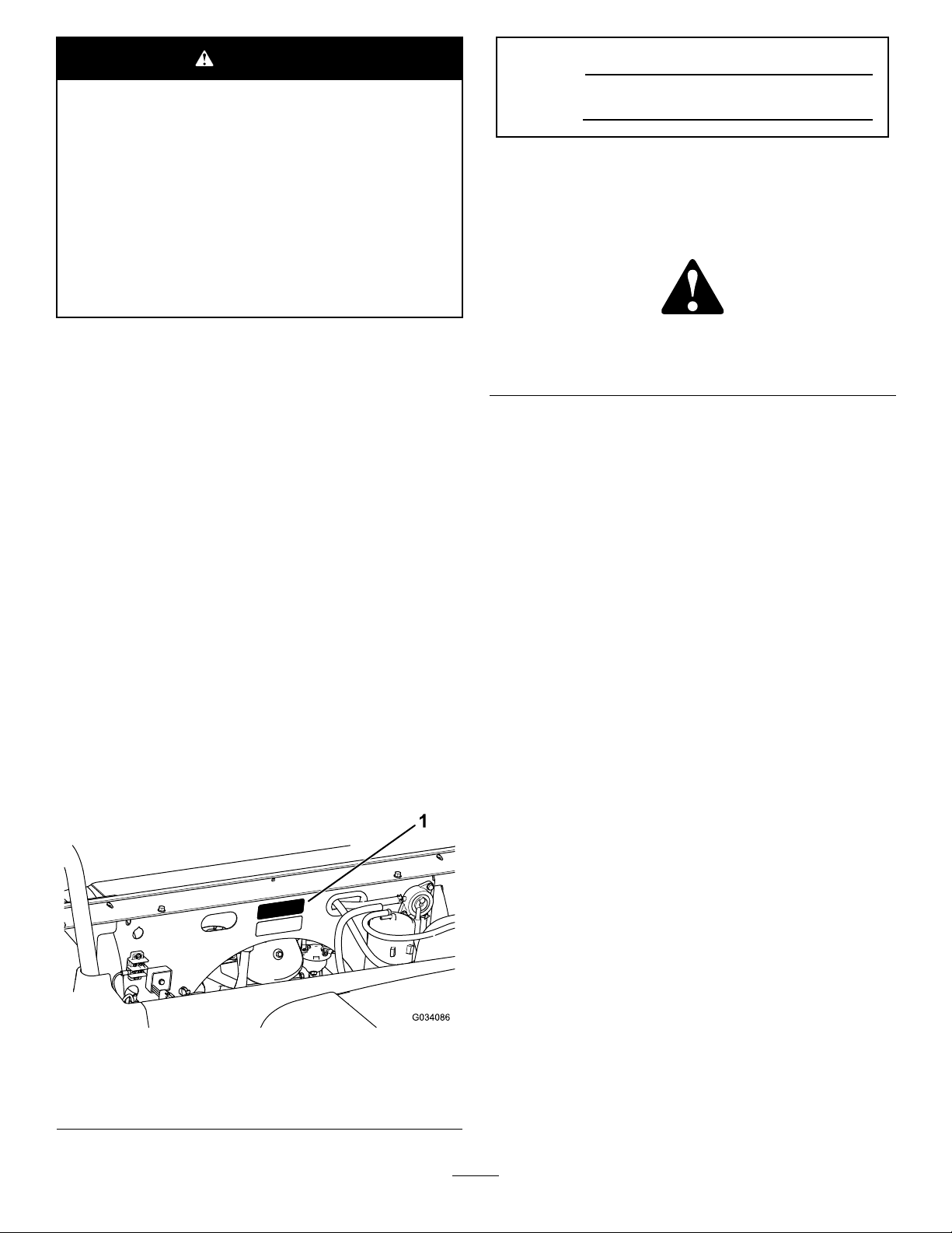
decal115-7739
115-7739
99-7345
1.Warning—readtheOperator'sManual.
2.Hotsurface/burnhazard—stayasafedistanceawayfrom
thehotsurface.
3.Entanglementhazard,belt—stayawayfrommovingparts;
keepallguardsinplace.
4.Crushinghazard,cargobed—usetheproprodtosupport
thecargobed.
115-2047
1.Warning—donottouchthehotsurface.
decal99-7345
1.Falling,crushinghazard,bystanders—noridersonmachine
decal120-9570
120-9570
1.Warning—stayawayfrommovingparts;keepallguards
andshieldsinplace.
decal115-2047
131-8411
1.Headlight—on3.Raisethebed.
2.Headlight—off
4.Lowerthebed.
7
decal131-8411
Page 8
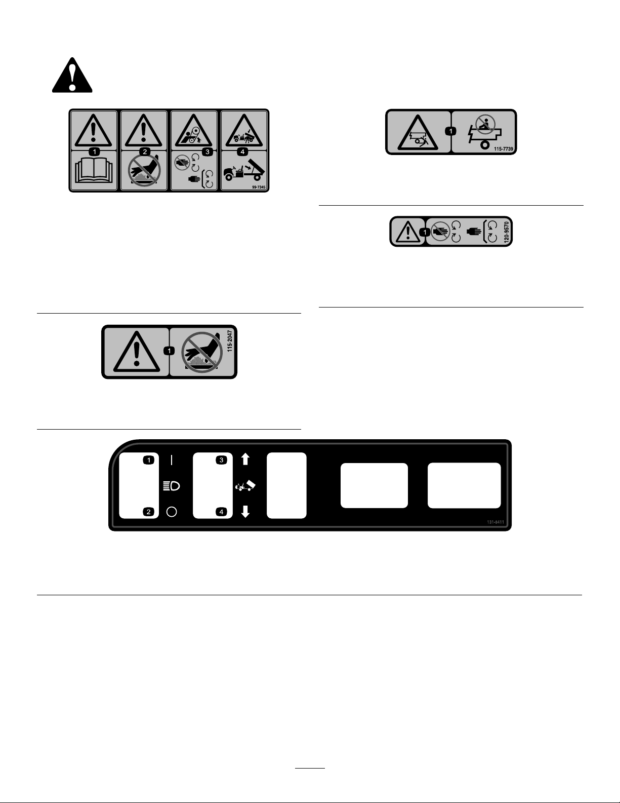
decal131-8412
131-8414
decal131-8414
131-8412
1.Warning—readthe
1.Horn
2.Forward
3.Neutral
5.Off
6.On
7.Turningon—1)Sitinthe
Operator'sManual.
driver'sseat;2)Disengage
theparkingbrake;3)Turn
thekeyswitchtothestart
position;4)Pushdownon
thepedal.
4.Reverse
8.Turningoff—1)Release
2.Warning—receiveproper
trainingbeforeoperating
themachine.
thepedal;2)Engagethe
parkingbrake;3)Turn
thekeyswitchtothestop
position;4)Removethe
keyfromthekeyswitch.
3.Tippinghazard—drive
slowlyacrossorupslopes;
taketurnsslowly;donot
exceedspeedsof25kph
(16mph);driveslowly
whenhaulingcargo;drive
slowlyonuneventerrain.
4.Fallinghazard;severing
hazardoflimbs—donot
carrypassengersinthe
bed;donotcarryextra
passengersinbetween
theseats;donotputyour
armsorlegsoutsideofthe
machinewhileoperating.
8
Page 9
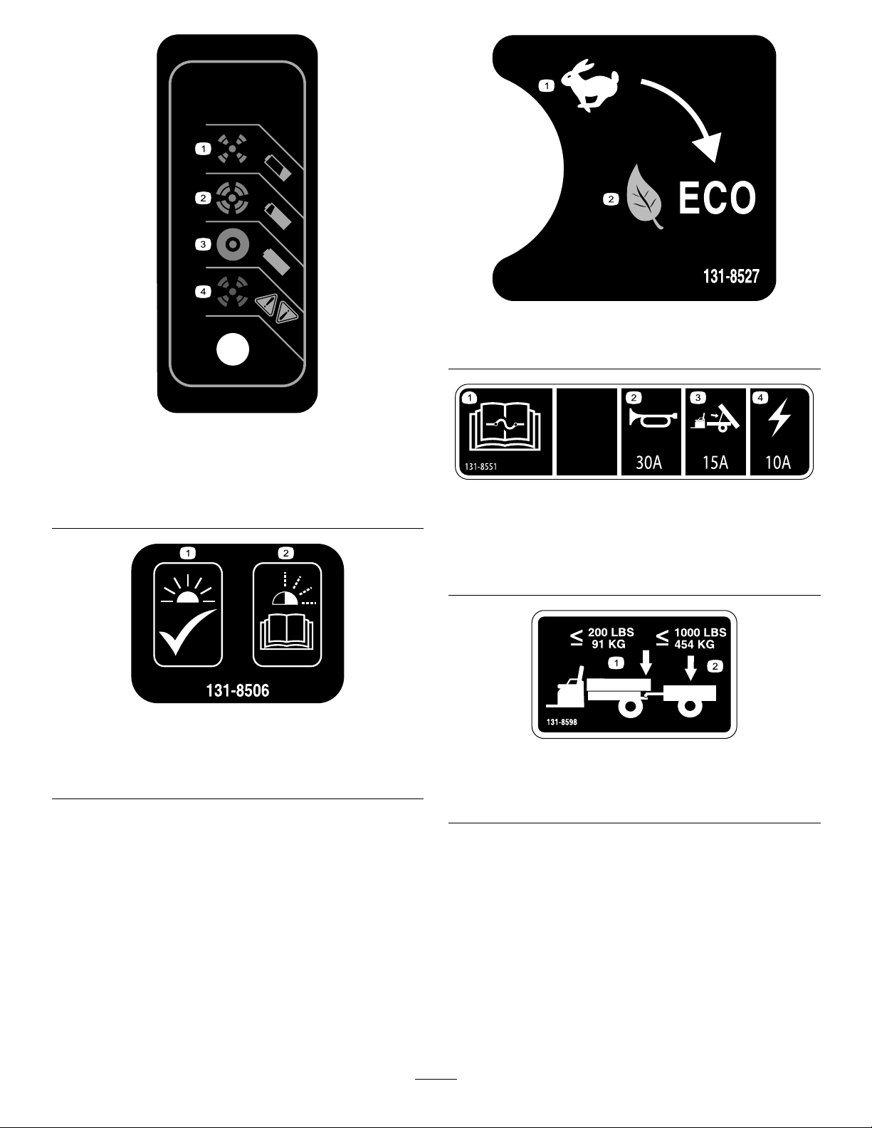
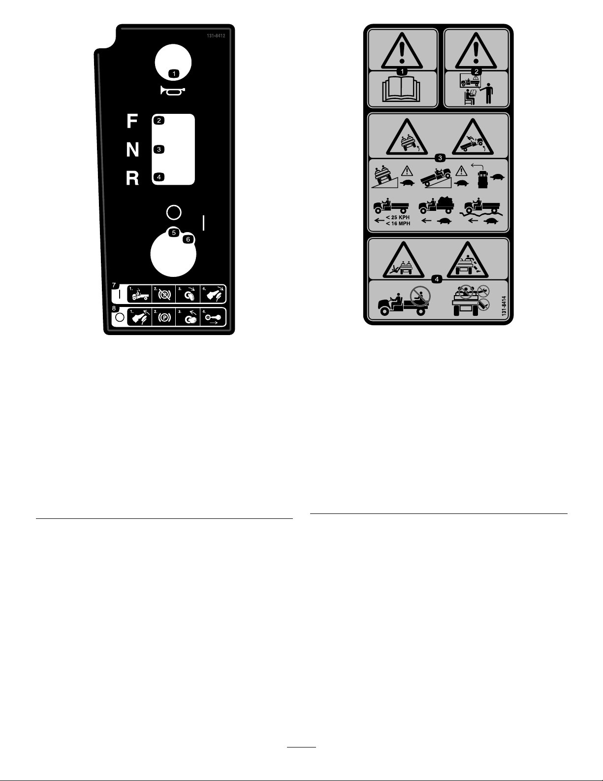
decal131-8527
131-8527
131-8495
1.Thebatteryisempty .3.Thebatteryischarged.
2.Thebatteryisalmost
charged.
4.Chargerfault;refertothe
chargermanualforthe
faultcodes.
131-8506
1.Solidlight—unitis
preparedforoperation.
2.Flashinglight—refertothe
chargermanualforthe
faultcodes.
1.Performancemode
decal131-8495
2.Ecomode
decal131-8551
131-8551
1.ReadtheOperator’s
Manualforfuse
information.
2.Horn(30A)4.Mainpower(10A)
decal131-8506
3.Optionalliftkit(15A)
decal131-8598
131-8598
1.Maximumbedweight91
kg(200lb)
2.Maximumtrailerweight
454kg(1,000lb)
9
Page 10
Setup
LooseParts
Usethechartbelowtoverifythatallpartshavebeenshipped.
ProcedureDescription
Steeringwheel
Steeringwheelcover
1
2
3
4
Washer(1/2inch)
Dustcover1
Nopartsrequired
Nopartsrequired
Operator'sManual
Engineowner'smanual1
Registrationcard1
PredeliveryInspectionForm1
CerticateofQuality
Key2
Note:Determinetheleftandrightsidesofthe
machinefromthenormaloperatingposition.
1
Qty.
1
1
1
–
–
1
1
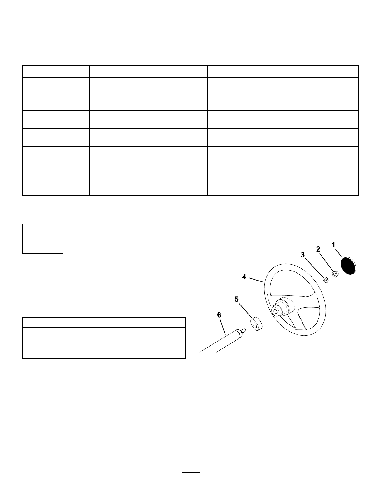
4.Securethesteeringwheeltotheshaftwiththe
locknut(1/2inch)andtightenitto18to30N∙m
(13to22ft-lb).
5.Installthecoveronthesteeringwheel(Figure3).
Installthesteeringwheel(International
modelsonly).
Checktheuidlevelsandtirepressure.
Burnish(break-in)thebrakes.
ReadtheOperator'sManualandview
thesetupmaterialbeforeoperatingthe
machine.
Use
InstallingtheSteering Wheel(InternationalModels Only)
Partsneededforthisprocedure:
1
Steeringwheel
1
Steeringwheelcover
1
Washer(1/2inch)
1Dustcover
Procedure
1.Ifthecoverisinstalled,removeitfromthehub
ofthesteeringwheel(Figure3).
2.Removethelocknut(1/2inch)fromthesteering
shaft(Figure3).
3.Slidethesteeringwheel,dustcover,andwasher
(1/2inch)ontothesteeringshaft(Figure3).
Note:Withthefrontwheelsstraight,orientthe
steeringwheelsothatthesmallerspokeonthe
steeringwheelisvertical.
Figure3
1.Steeringwheelcover4.Steeringwheel
2.Locknut(1/2inch)
3.Washer(1/2inch)6.Steeringshaft
5.Dustcover
g198932
10
Page 11

2
4
CheckingtheFluidLevels
andTirePressure
NoPartsRequired
Procedure
1.Checkthewaterlevelinthebatteriesbefore
youoperatethemachine;refertoCheckingthe
WaterLeveloftheBatteries(page38).
2.Ensurethatthebatteriesarecharged;referto
ChargingtheBatteries(page36).
3.Checkthebrake-uidlevelbeforeyouoperate
themachine;refertoCheckingtheBrake-Fluid
Level(page44).
4.Checktheairpressureinthetires;referto
CheckingtheTirePressure(page20).
3
ReadingtheManualand ViewingtheSetupMaterial
Partsneededforthisprocedure:
1
Operator'sManual
1Engineowner'smanual
1Registrationcard
1PredeliveryInspectionForm
1
CerticateofQuality
2Key
Procedure
•ReadtheOperator'sManualandtheengine
owners'smanual.
•Fillouttheregistrationcard.
•CompletethePredeliveryInspectionForm.
•ReviewtheCerticateofQuality.
BurnishingtheBrakes
NoPartsRequired
Procedure
Toensureoptimumperformanceofthebrakesystem,
burnish(break-in)thebrakesbeforeuse.
1.Bringthemachineuptofullspeed,applythe
brakestorapidlystopthemachinewithout
lockingupthetires.
2.Repeatthisprocedure10times,waiting1minute
betweenstops,toavoidoverheatingthebrakes.
Important:Thisprocedureismosteffective
ifthemachineisloadedwith227kg(500lb).
11
Page 12
ProductOverview
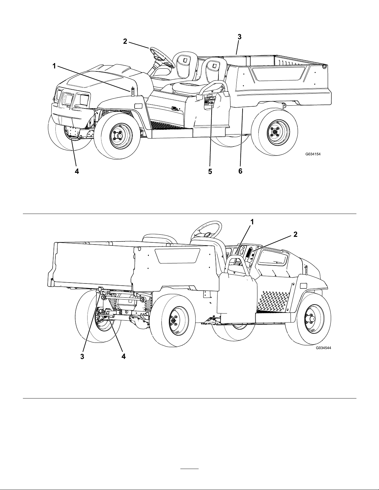
g034154
Figure4
1.Hoodlatch
2.Steeringwheel
3.Cargobed
4.Towingtongue
5.Batterycharger
6.Cargo-bedlever
g034544
Figure5
1.Passengerhandhold3.Rearcargo-bed-accessorymount
2.Parking-brakelever4.Trailerhitch
12
Page 13
Controls
ControlPanel
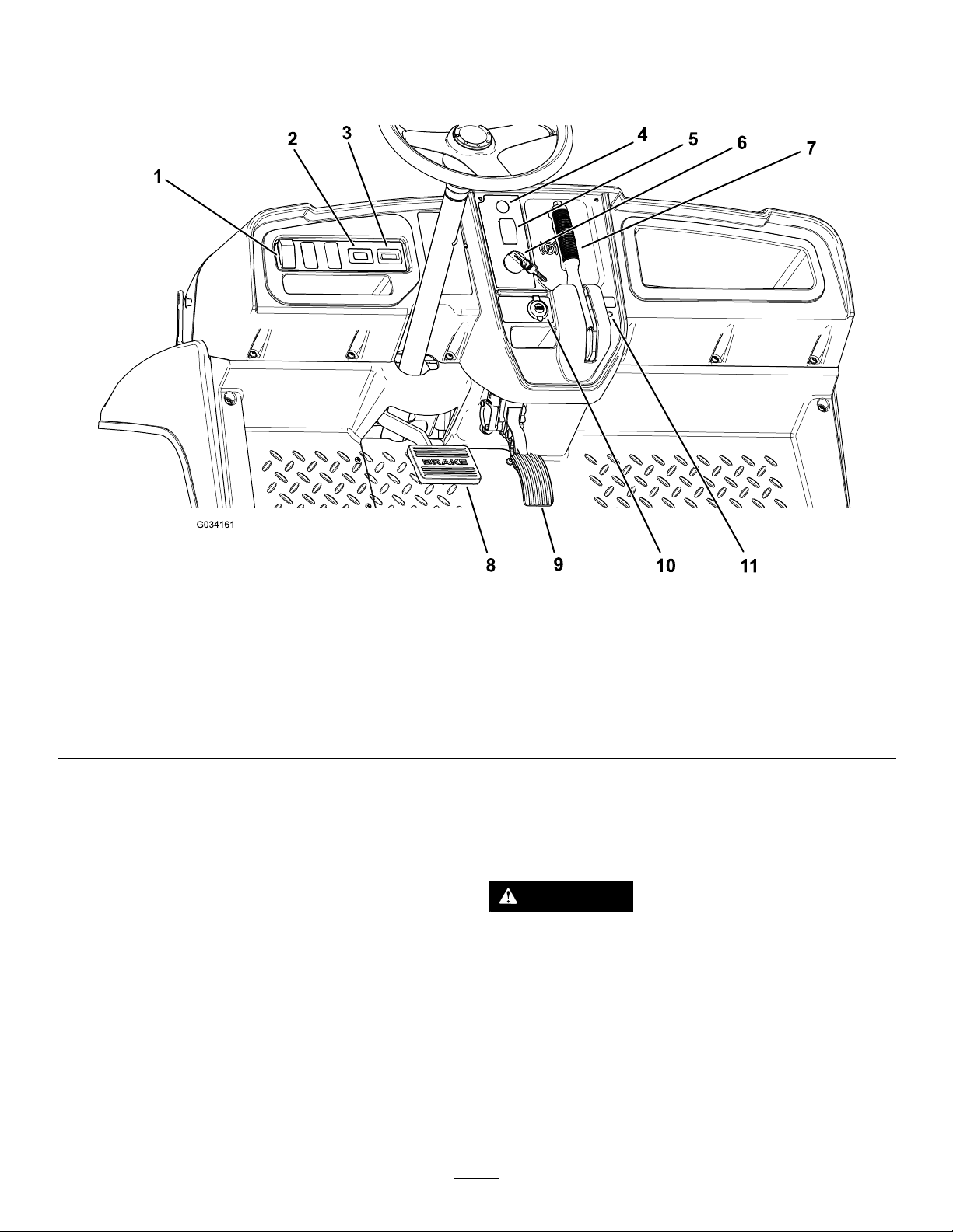
Figure6
1.Lightswitch7.Parking-brakelever
2.Hourmeter8.Brakepedal
3.Battery-dischargeindicator9.Acceleratorpedal
4.Hornbutton(Internationalmodelsonly)10.USBpowerpoint
5.Gear-shiftselector11.Status-indicatorlight
6.Keyswitch
AcceleratorPedal
Usetheacceleratorpedal(Figure6)tovaryground
speedofthemachine.Pressingdowntheaccelerator
pedalstartsthemachine.Pressingthepedalfarther
increasesgroundspeed.Releasingthepedalslows
themachine,andthemachineshutsoff.
BrakePedal
Usethebrakepedaltostoporslowthemachine
(Figure6).
CAUTION
Operatingamachinewithwornorincorrectly
Themaximumforwardspeedinperformancemodeis
26km/h(16mph)asshowninFigure9.
Themaximumforwardspeedineconomymodeis19
km/h(12mph)asshowninFigure9.
adjustedbrakescanmayresultinpersonal
injury.
Ifthebrakepedaltravelstowithin25mm(1
inch)ofthemachineoorboard,adjustor
repairthebrakes.
g034161
13
Page 14
Parking-BrakeLever
DirectionSelector
Theparking-brakeleverislocatedonthecontrol
panel(Figure7).
Wheneveryoushutofftheengine,engagetheparking
braketopreventthemachinefromaccidentally
moving.Ifthemachineisparkedonasteepgrade,
ensurethatyouengagetheparkingbrake.
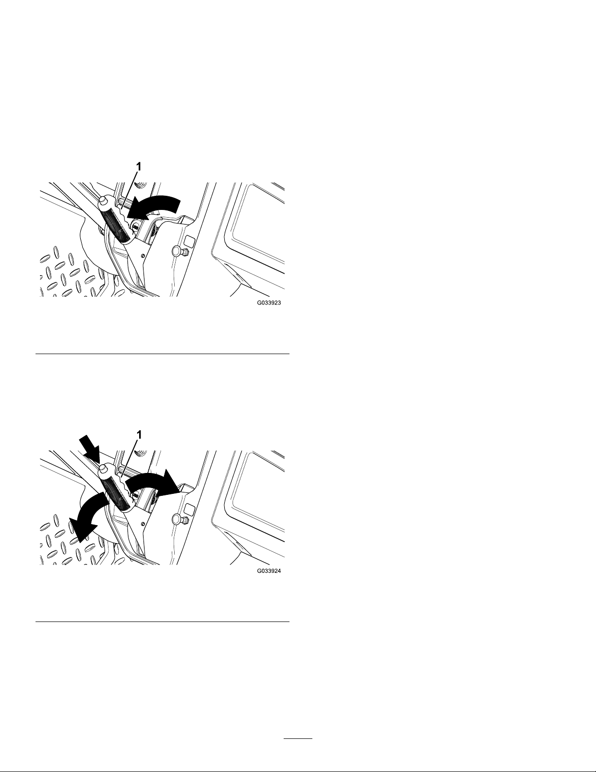
Toengagetheparkingbrake,pulltheparking-brake
levertowardyou(Figure7).
Figure7
Thedirectionselectorislocatedtotheleftofthe
parking-brakelever.Thedirectionselectorhas3
positions:FORWARD,REVERSE,andNEUTRAL(Figure
6).
Note:Themachinecanbeoninanyofthe3
positions,butonlymovesintheFORWARDand
REVERSEpositions.
Important:Alwaysstopthemachinebefore
changingdirection.
HornButton
InternationalModelsOnly
Thehornbuttonislocatedonthecontrolpanel(Figure
6).Pressthehornbuttontosoundthehorn.
LightSwitch
Usethelightswitch(Figure6)toilluminatethe
headlights.Pushthelightswitchuptoturnonthe
g033923
headlights.Pushthelightswitchdowntoturnoffthe
lights.
1.Parking-brakelever
Todisengagetheparkingbrake,pushdownthe
buttonontopoftheparking-brakelever,pullthe
parking-brakelevertowardyoutoreleasepressure,
andthenpushtheparking-brakeleverforward(Figure
8).
Figure8
1.Parking-brakelever
Battery-DischargeIndicator
Thebattery-dischargeindicatorislocatedto
theleftofthesteeringcolumn(Figure6).The
battery-dischargeindicatorindicatestheremaining
chargeinthebatteries.Whenthebatteriesarefully
charged,10indicatorbarsextendfromthe0tothe1
position.Asyouusethecharge,theindicatorbars
disappear,startingattherightsideofthemeter.For
detailedinformationonthebatterymeter,referto
UnderstandingandUsingtheBatterySystem(page
21).
HourMeter
Thehourmeterislocatedtotherightofthelight
switch(Figure6).Usethehourmetertondoutthe
totalnumberofoperatinghours.Thehourmeter
startstofunctionwheneveryouturnthekeyswitchto
theONpositionorifthemachineisrunning.
g033924
Note:Whenthemachineisrunning,thehourmeter
blinkscontinuously,recordingusage.
USBPowerPoint
TheUSBpowerpointislocatedtotheleftofthe
parking-brakelever(Figure6).Usethepowerpoint
topowermobiledevices.
Important:WhenyouarenotusingtheUSB
powerpoint,inserttherubberplugtoprevent
damagetothepowerpoint.
14
Page 15
KeySwitch
Status-IndicatorLight
Usethekeyswitch(Figure6),torunandshutoffthe
machine.
Thekeyswitchhas2positions:ONandOFF.Rotate
thekeyclockwisetotheONpositiontooperatethe
machine.Whenyoustopthemachine,rotatethekey
counterclockwisetotheOFFpositiontoshutoffthe
machine.Removethekeywheneveryouleavethe
machine.
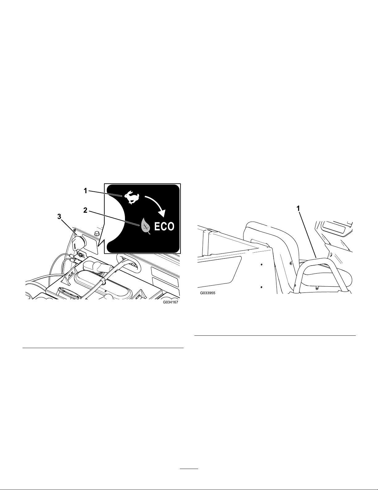
SupervisorSpeed-LimitSwitch
Thesupervisorspeed-limitswitch,locatedunder
theseatassembly,has2positions:PERFORMANCE
andECONOMY.Rotatetheswitchclockwisetothe
ECONOMYpositiontolimitthemaximummachine
speedto19km/h(12mph).Rotatetheswitch
counterclockwisetothePERFORMANCEpositionto
restorethemaximumspeedofthemachineto26km/h
(16mph)asshowninFigure9.
Thestatus-indicatorlightislocatedtotherightofthe
parking-brakeleveronthecontrolpanel(Figure6).
Whenthemachineisturnedon,thegreen
status-indicatorlightilluminateseithersolidorblinking.
Ifthelightissolid,thisindicatesthatthemachineis
readyfornormaloperation.Ifthelightisblinking,
thereisanissuethatneedstoberesolvedbefore
continuingwithnormaloperationofthemachine.
Ifthestatus-indicatorlightblinks2times,this
indicatesthattheparkingbrakeisengagedwhilein
theFORWARDorREVERSEpositiononthedirection
selector.Disengagetheparkingbraketoshutoffthe
status-indicatorlight.
RefertoTroubleshooting(page48)ifthe
status-indicatorlightblinksmorethan2times.
PassengerHandholds
Thepassengerhandholdsarelocatedontheoutside
ofeachseat(Figure10).
1.PERFORMANCEposition
2.ECONOMYposition
Figure9
3.Supervisorspeed-limit
g033955
g034167
switch
1.Passengerhandhold
15
Figure10
PassengerSideShown
Page 16

Specications
Note:Specicationsanddesignaresubjecttochangewithoutnotice.
Baseweight
Ratedcapacity(onlevelground)
Maximumgrossvehicleweight(GVW)—onlevelground1177kg(2,595lb)total,includingalloftheweightslistedabove
Maximumcargocapacity(onlevelground)363kg(800lb)total,includingrear-mountedaccessories
Maximumrearcargobedaccessorymountcapacity
Towcapacity
Overallwidth119cm(47inches)
Overalllength302cm(119inches)
Overallheight127.5cm(50.2inches)
Groundclearance
Wheelbase
Wheeltread(centerlinetocenterline)
Cargobedlength
Cargobedwidth
Cargobedheight28cm(11inches)inside
Dry633kg(1,395lb)
544kg(1,200lb)total,including91kg(200lb)operatorand91kg
(200lb)passenger,load,accessories,andattachments
45kg(100lb)total
Tongueweight:91kg(200lb)
Maximumtrailerweight:454kg(1,000lb)
21.6cm(8.5inches)atthefrontwithnoloadoroperator
14cm(5.5inch)attherearwithnoloadoroperator
220cm(86.6inches)
Front:119cm(47inches)
Rear:119cm(47inches)
Inside:102cm(40inches)
Outside:1 14.3cm(45inches)
Inside:98cm(38.5inches)
Outsideofthemoldedfenders:107.3cm(42.3inches)
*SpecicationslistedarewithTrojanT-125batteries.**Installingnon-standardbatteriesmayreducethe
cargo-bedcapacity.
Attachments/Accessories
AselectionofToroapprovedattachmentsandaccessoriesisavailableforusewiththemachinetoenhance
andexpanditscapabilities.ContactyourAuthorizedServiceDealerorDistributororgotowww.Toro.comfora
listofallapprovedattachmentsandaccessories.
16
Page 17

Operation
OperatingtheCargoBed
Note:Determinetheleftandrightsidesofthe
machinefromthenormaloperatingposition.
CAUTION
Araisedbedfullofmaterialwithouttheproper
safetysupportmaylowerunexpectedly.
Workingunderanunsupportedraisedbed
couldinjureyouorothers.
•Beforeservicingormakingadjustmentsto
themachine,parkthemachineonalevel
surface,engagetheparkingbrake,shutoff
theengine,andremovethekey.
•Removeanyloadmaterialfromthebed
orotherattachment,andinsertthesafety
supportonafully-extendedcylinderrod
beforeworkingunderaraisedbed.
ThinkSafetyFirst
Carefullyreadallthesafetyinstructionsandsymbols
inthesafetysection.Knowingthisinformationcould
helpyouorbystandersavoidinjury.
DANGER
RaisingtheCargoBedtothe DumpPosition
WARNING
Araisedbedcouldfallandinjurepersonsthat
areworkingbeneathit.
•Alwaysusetheproprodtoholdthebedup
beforeworkingunderthebed.
•Removeanyloadmaterialfromthebed
beforeraisingit.
WARNING
Drivingthemachinewiththecargobedraised
couldcausethemachinetotiporrolleasier.
Youcoulddamagethestructureofthecargo
bedifyouoperatethemachinewiththebed
raised.
•Operatethemachinewhenthecargobed
isdown.
•Afteremptyingthecargobed,lowerit.
Operatingonwetgrassorslopescancause
slidingandlossofcontrol.
Wheelsdroppingoveredgescancause
rollovers,whichmayresultinseriousinjury,
death,ordrowning.
Toavoidlossofcontrolandpossibilityof
rollover:
•Donotoperateneardropoffsornearwater.
•Reducespeedanduseextremecautionon
slopes.
•Avoidsuddenturnsorrapidspeed
changes.
CAUTION
Ifaloadisconcentratednearthebackofthe
cargobedwhenyoureleasethelatches,the
bedmayunexpectedlytipopen,injuringyou
orbystanders.
•Centerloadsinthecargobed,ifpossible.
•Holdthecargobeddownandensurethat
nooneisleaningoverthebedorstanding
behinditwhenreleasingthelatches.
•Removeallcargofromthebedbefore
liftingthebeduptoservicethemachine.
1.Pulltheleveronleft,insideofthecargobed
towardyouandliftthecargobedup(Figure11).
17
Page 18

RaisingtheCargoBedtothe ServicePosition
1.Pulltheleveronleft,insideofthecargobed
towardyouandliftthecargobedup(Figure11).
2.Pullproprodintotheservicepositiondetentslot
tosecurethebedformaintenance(Figure12).
LoweringtheCargoBed
Figure11
1.Cargo-bedlever
2.Pulltheproprodintothedumppositiondetent
slottosecurethebedfordumping(Figure12).
Figure12
1.Servicepositiondetent
slot
2.Proprod
3.Dumppositiondetentslot
g034019
WARNING
Theweightofthebedmaybeheavy.Hands
orotherbodypartscouldbecrushed.
Keepyourhandsandotherbodypartsaway
whenloweringthebed.
1.Raisethecargobedslightlybyliftinguponthe
latchlever(Figure11).
2.Pulltheproprodoutofthedetentslot(Figure
12).
3.Lowerthebeduntilitlatchessecurely.
g034021
18
Page 19

OpeningtheTailgate
ClosingtheTailgate
1.Ensurethatthecargobedisdownandlatched.
2.Usingbothhands,raisethetailgateusingthe
ridgenearthetopofthetailgate(Figure13).
3.Lowerthetailgateuntilitisushwiththebottom
ofthecargobed(Figure13).
Ifyouunloadedloosematerialsuchassand,
landscapingrock,orwoodchipsfromthecargobedof
themachine,someofthematerialthatyouunloaded
mayhavelodgedinthehingeareaofthetailgate.
Performthefollowingstepsbeforeclosingthetailgate.
1.Useyourhandstoremoveasmuchofthe
materialfromthehingeareaaspossible.
2.Rotatethetailgatetoapproximatelythe45°
position(Figure14).
g034023
Figure14
Figure13
1.Rotatethetailgateback
andforthseveraltimes.
2.Rotatethetailgateto
g034022
approximatelythe45°
position.
3.Hingearea
3.Useashort,shakingmotiontorotatethetailgate
backandforthseveraltimes(Figure14).
Note:Thisactionhelpsmovematerialaway
fromthehingearea.
4.Lowerthetailgateandcheckformaterial
remaininginthehingearea.
5.Repeatsteps1through4untilthematerialis
removedfromthehingearea.
6.Rotatethetailgateupandliftthetailgateintothe
notchesinthecargobed.
19
Page 20

UsingtheRearCargoBed
PerformingDaily
AccessoryMount
Usetherearcargobedaccessorymounttoattach
accessoriestotherearofthemachine.
Capacity:45kg(100lb)
1.Loosenthe“T”handlebyrotatingitclockwise
(Figure15).
Figure15
1.Receiver
2.Insertyouraccessoryintothereceiveruntilthe
holesalign(Figure15).
3.Securetheassembledaccessorytothereceiver
tubeusingtheclevispinandhairpincotter
suppliedwiththeaccessory .
2.“T”handle
Maintenance
Beforestartingthemachineeachday,perform
theEachUse/DailyprocedureslistedinDaily
MaintenanceChecklist(page27).
CheckingtheTirePressure
ServiceInterval:Beforeeachuseordaily
Frontandreartiresairpressurespecication:165
to207kPa(24to30psi)
Important:Donotexceedthemaximumair
pressureindicatedonthesidewallofthetire.
Note:Theairpressureneededinthetiresis
determinedbythepayloadthatyouintendtocarry.
1.Checktheairpressureinthetires.
g034545
•Uselowerairpressureinthetiresforlighter
payloads,forlesssoilcompaction,fora
smootherride,andtominimizetiremarkson
theground.
•Usehigherairpressureinthetiresfor
carryingheavierpayloadsathigherspeeds.
2.Ifnecessary ,adjusttheairpressureinthetires
byaddingorremovingairinthetires.
4.Tightenthe“T”handlebyrotatingit
counterclockwise(Figure16).
Figure16
1.“T”handle
g001055
Figure17
g034546
20
Page 21

UnderstandingandUsing theBatterySystem
UnderstandingDeep-Cycle Batteries
Themachinecontains8deep-cycle,lead-acid
batteriesthatsupplypowertothemotorand
accessories.Adeep-cyclebatteryisnotthesame
asanautomobilebattery .Anautomobilebattery
isdesignedtoprovideasurgeofpowertostart
themachineandmoderatepowertorunthelights
andaccessorieswhenthemotorifofforidling.
Thealternatorthencontinuouslychargesasthe
automobileruns.Assuch,anautomobilebattery
seldomdropsbelow90%ofthemaximumcharge
level.
Adeep-cyclebatteryisdesignedtobeaprimarypower
sourcetoprovideasustainedoutput.Deep-cycle
batteriesaretypicallydischargedaslowas20to30%
ofthemaximumchargelevel.Adischargethislowis
consideredadeepdischarge.
Important:Repeateddeep-dischargecycles
reducesthebatterylife.
Lead-acidbatteriesproduceelectricitythrougha
chemicalreactionbetweenleadplatesandsulfuric
acid.Chargingabatteryreversesthechemical
reaction,allowingthebatterytoonceagainproduce
electricity.
Abatteryisaperishableitemthathasalimited
lifetime(Figure18).Whenabatteryisnew,itrequires
abreak-inperiodtoestablishefcientelectrical
production.Thisbreakinperiodusuallyrequires100
to150discharge/chargecycles.
Afterthebreak-inperiod,thebatterymaintainsahigh
capacityformanycycles.Thenumberofcyclesthata
batteryperformsdependsonthefollowing:
•Batterymaintenance—impropermaintenance
severelyreducesthelifeofthebatteries.
•Depthofdischargebetweenchargecycles—the
deeperthebatteriesaredischargedona
regularbasisbetweencharges,theshorterthe
servicelifethebatterieswillhave.
•Chargefrequency—fullychargethebatteries
wheneverpossible.
Important:Fullydischargingthebatteries
damagesthemandreducestheirlife.
•Lowwaterlevels—iftheleadplatesbecome
exposed,itmaypermanentlydamagethe
batteries.Performthefollowingtomaintainthe
electrolytelevel:
Afterfullychargingthebatteries,llthe
batterieswithdistilledordeionizedwater;referto
CheckingtheWaterLeveloftheBatteries(page
38)andAddingDistilledorDeionizedWatertothe
Batteries(page38).
Important:Fullychargethebatteriesbefore
addingthewatertothebatteries.While
charging,theelectrolyteincreasesinvolume,
andllingalowbatterybeforefullycharging
thebatteriescancausetheelectrolyteto
overowandleakoutofthevent.
Attheendofthebatterylife,thebatteriesgradually
loseelectriccapacity.
Figure18
Battery-LifetimeT able
1.Batterycapacity
2.Discharge/chargecycles5.Endofthebatterylife
3.Break-inperiod(100to
150cycles)
4.Primebatterylife
g004049
21
Page 22

UsingtheBatterySystem
Whenyourbatteriesarefullycharged,thetenth
bar(farright)illuminatesonthebattery-discharge
indicator(Figure19).
Figure19
Ifyoucontinuetousethemachinewithonly2bars
remaining,bars1and2alternatelyash.
Important:Whenonlythesecondbarfromthe
leftremainsonthebattery-dischargeindicator,
themachinemayenterareduced-speedmode;
thismodeaidsinprotectingthebatteries,but
prolongedoperationinthismodecandamage
thebatteriesand/orthemachine.Avoiddraining
yourbatteriesdowntothesecondbarfromthe
lefttopreventthisissue.Chargethebatteries
immediately.
Ifthebatteriesbecomefullydischarged,the
machineshutsdown.Donotallowthebatteriesto
becomefullydischarged.
Important:Toobtainmaximumbatterylife,
alwayschargethebatteriesbeforethecharge
reachesthesecondbarfromtheleftonthe
screen.Regularlydepletingthebatteriestolower
thanthesecondbarfromtheleftreducesthelife
g192308
ofthebatteries.
1.Battery-discharge
indicator
2.Charge-indicatorbars
Asyouusethemachine,thebarsdisappearasthe
electricalcapacityofthebatteriesisused.
Whenonlythesecondbarfromtheleftremainson
thebattery-dischargeindicator,itisagoodtimeto
charge(Figure20).
Figure20
1.The2leftbarsalternatelyblinkuntilyouchargethe
batteries.
g192309
22
Page 23

StoppingtheMachine
LoadingtheCargoBed
Important:Whenstoppingthemachineon
anincline,usetheservicebrakestostopthe
machineandengagetheparkingbraketoholdthe
machineinplace.Usingtheacceleratortostall
themachineonthehillcanoverheatthemotoror
drainthebatteries.
1.Removeyourfootfromtheacceleratorpedal.
2.Slowlypressthebrakepedaltoapplytheservice
brakesuntilthemachinecomestoacomplete
stop.
Note:Thestoppingdistancemayvary
dependingonthemachineloadandspeed.
BreakinginaNewMachine
ServiceInterval:Aftertherst100hours—Perform
thebreakinginanewmachine
guidelines.
Performthebreakinginanewmachineguidelines
toprovideproperperformanceandlonglifeforthe
machine.
•Checkthebrakeuidandthewaterlevelinthe
batteriesregularly.
•Avoidhardbrakingsituationsfortherstseveral
hoursofnewmachinebreak-inoperation.New
brakeliningsmaynotbeatoptimumperformance
untilseveralhoursofusehascausedthebrakes
tobecomeburnished(broken-in).
•RefertoMaintenance(page26)foranyspecial
lowhourchecks.
•Checkthefrontsuspensionpositioningandadjust
itifnecessary.
Usethefollowingguidelineswhenloadingthecargo
bedandoperatingthemachine:
•Observetheweightcapacityofthemachineand
limittheweightoftheloadthatyoucarryinthe
cargobedasdescribedinSpecications(page
16)andonthegrossvehicleweighttagofthe
machine.
Note:Theloadratingisspeciedformachine
operationonalevelsurfaceonly.
•Reducetheweightoftheloadthatyoucarryinthe
cargobedwhenoperatingthemachineonhills
androughterrain.
•Reducetheweightoftheloadthatyoucarrywhen
thematerialsaretall(andhaveahighcenterof
gravity),suchasastackofbricks,landscaping
timbers,orfertilizerbags.Distributetheloadas
lowaspossibletoensurethattheloaddoesnot
reduceyourabilitytoseebehindthemachine
whenoperatingit.
•Keeploadscenteredbyloadingthecargobedas
follows:
–Evenlypositiontheweightinthecargobed
fromsidetoside.
Important:Tippingoverismorelikelyto
occurifthecargobedisloadedto1side.
–Evenlypositiontheweightinthecargobed
fromfronttoback.
Important:Lossofsteeringcontrolorthe
machinemaytipoverifyoupositionthe
loadbehindtherearaxleandthetraction
onthefronttiresisreduced.
•Useextracautionwhentransportingoversized
loadsinthecargobed,particularlywhenyou
cannotcenterthewightoftheoversizeloadtothe
cargobed.
•Wheneverpossible,securetheloadbybindingit
tothecargobedsothatitdoesnotshift.
•Whentransportingliquidinalargetank(such
asasprayertank),usecautionwhendriving
themachineuphillordownhill,whensuddenly
changingspeedorstopping,orwhendrivingover
toughsurfaces.
Thecapacityofthecargobedis0.28m
Theamount(volume)ofmaterialthatyoucanplace
inthebedwithoutexceedingtheloadratingsofthe
machinecanvarygreatlydependingonthedensity
ofthematerial.
23
3
(10ft3).
Page 24

Refertothefollowingtableforloadvolumelimitswith
variousmaterials:
MaterialDensity
Gravel,dry1522kg/m
Gravel,wet1922kg/m
Sand,dry1442kg/m
Sand,wet1922kg/m
Wood
Bark
Earth,packed
721kg/m
3
(95
3
lb/ft
)
3
(120
3
lb/ft
)
3
(90
3
lb/ft
)
3
(120
3
lb/ft
)
3
(45lb/ft
<721kg/m
1602kg/m
3
(<45
3
lb/ft
)
3
(100
3
lb/ft
)
MaximumCargo
BedCapacity
(onlevelground)
Full
3/4Full
Full
3/4full
3
)
Full
Full
3/4Full
(approximately)
TransportingtheMachine
Useatrailerwithfull-widthrampstomovethe
machinealongdistance.Ensurethatyousecurethe
machinetothetrailer.RefertoFigure21andFigure
22forthetie-downlocationsonthemachine.
g034029
Figure21
1.Towingtongueandtie-downpoint(frontofthemachine)
Note:Loadthemachineonthetrailerwiththefront
ofthemachinefacingforward.Ifthatisnotpossible,
securethemachinehoodtotheframewithastrap,
orremovethehoodandtransportandsecureit
separatelyorthehoodmayblowoffduringtransport.
CAUTION
Looseseatsmayfalloffthemachineand
trailerwhentransportingthemachine,and
theseatsmaylandonanothermachineor
obstructtheroadway.
Removetheseatsormakesurethattheseats
aresecurelyfastenedtothecouplinginthe
seatshroud.
g034273
Figure22
1.Reartie-downpoints
24
Page 25

TowingtheMachine
TowingaTrailer
Incaseofanemergency,youcantowthemachine
forashortdistance;however,thisshouldnotbea
standardoperatingprocedure.
WARNING
Towingatexcessivespeedscouldcausea
lossofsteeringcontrol,resultinginpersonal
injury.
Nevertowthemachineatfasterthan8km/h
(5mph).
Towingthemachineisa2-personjob.Ifyoumust
movethemachineaconsiderabledistance,transport
itonatruckortrailer;refertoT owingaTrailer(page
25).
1.Shutoffthemachineandremovethekey.
Important:Ifyoutowthemachinewiththe
keyintheONposition,theelectricalsystem
maybedamaged.
2.Afxatowlinetothetongueatthefrontofthe
machine’sframe(Figure21).
3.Disengagetheparkingbrake.
Themachineiscapableofpullingtrailers.2typesof
towhitchesareavailableforthemachine,depending
onyourapplication.ContactyourAuthorizedT oro
Distributorfordetails.
Whenhaulingcargoortowingatrailer,donot
overloadyourmachineortrailer.Overloadingeither
themachineorthetrailercancausepoorperformance
ordamagetothebrakes,axle,motor,transaxle,
steering,suspension,bodystructure,ortires.
Alwaysloadatrailerwith60%ofthecargoweightin
thefrontofthetrailer.Thisplacesapproximately10%
ofthegrosstrailerweight(GTW)onthetowhitchof
themachine.
Themaximumcargoloadshouldnotexceed454kg
(1,000lb),includingtheGTW.Forexample,ifthe
GTWis181.5kg(400lb)thenthemaximumcargo
loadis544kg(1,200lb)includingoperator(s).
Toprovideadequatebrakingandtraction,alwaysload
thecargobedwhenusingatrailer.Donotexceed
theGTWorGVWlimits.
Avoidparkingamachinewithatraileronahill.Ifyou
mustparkonahill,engagetheparkingbrakeand
blockthetiresofthetrailer.
25
Page 26

Maintenance
Note:Determinetheleftandrightsidesofthemachinefromthenormaloperatingposition.
Note:Downloadacopyoftheelectricalschematicbyvisitingwww.T oro.comandsearchingforyourmachine
fromtheManualslink.
WARNING
Failuretoproperlymaintainthemachinecouldresultinprematurefailureofmachinesystems
causingpossibleharmtoyouorbystanders.
Keepthemachinewellmaintainedandingoodworkingorderasindicatedintheseinstructions.
RecommendedMaintenanceSchedule(s)
MaintenanceService
Interval
Aftertherst100hours
Beforeeachuseordaily
Every25hours
Every100hours
Every300hours
Every400hours
Every800hours
Every1,000hours
MaintenanceProcedure
•Performthebreakinginanewmachineguidelines.
•Checkthetirepressure.
•Chargethebatteries.
•Checkthewaterlevelofthebatteries.
•Checkthebrake-uidlevel.
•Cleanthebatteries.
•Checkthewaterlevelofthebatteriesandadddistilledordeionizedwatertothe
batteries(ifnecessary).
•Greasethebearingsandbushings.
•Checktheconditionofthetiresandrims.
•Torquethewheel-lugnuts.
•Checkthefrontwheelcamberandtoe-in.
•Checkthetransaxle-uidlevel.
•Checkthetransaxleforleaks.
•Inspectthebrakes.
•Greasethefrontwheelbearings.
•Replacetheserviceandparking-brakepads.
•Changethetransaxleuid.
•Changethebrakeuid.
26
Page 27

DailyMaintenanceChecklist
Duplicatethispageforroutineuse.
Fortheweekof: MaintenanceCheckItem
Checkbrakeandparking
brakeoperation.
Checkgearshift/neutral
operation.
Checkthewaterlevelof
thebatteries.
Checkbrake-uidlevel.
Checkunusualoperating
noises.
Checktirepressure.
Checkuidleaks.
Checkinstrument
operation.
Checkaccelerator
operation.
Lubricateallgrease
ttings.
Touchupanydamaged
paint.
MondayTuesdayWednesdayThursdayFriday
SaturdaySunday
MaintainingtheMachineunderSpecialOperating Conditions
Important:Ifthemachineissubjectedtoanyoftheconditionslistedbelow,performmaintenance
twiceasfrequently:
•Desertoperation
•Coldclimateoperation—below10°C(50°F)
•Trailertowing
•Frequentoperationindustyconditions
•Constructionwork
•Afterextendedoperationinmud,sand,water,orsimilardirtyconditions,haveyourbrakesinspectedand
cleanedassoonaspossible.Thispreventsanyabrasivematerialfromcausingexcessivewear.
27
Page 28

Pre-Maintenance
Procedures
WARNING
Raisethecargobedbeforeperforming
maintenance.Araisedcargobedcanfalland
injurepersonsthatareunderneathit.
•Alwaysusetheproprodtoholdthecargo
bedupbeforeworkingunderneathit.
•Removeanyloadmaterialfromthecargo
bedbeforeworkingunderneathit.
MaintenanceSafety
•Donotallowuntrainedpersonneltoservicethe
machine.
•Beforeservicingormakinganyadjustmentstothe
machine,parkthemachineonalevelsurface,
engagetheparkingbrake,shutoffthemotor,and
removethekeytopreventaccidentalstartingof
themachine.
•Usejackstandstosupportthemachineor
componentswhenrequired.
•Donotworkunderaraisedbedwithouttheproper
bedsafetysupportinplace.
•Ensurethatallhydraulic-lineconnectorsaretight
andthatallthehydraulichosesandlinesarein
goodconditionbeforeapplyingpressuretothe
system.
•Beforedisconnectingorperforminganyworkon
thehydraulicsystem,relieveallpressureinthe
systembyshuttingoffthemotor,cyclingthedump
valvefromraisetolower,and/orloweringthecargo
bedandattachments.Placetheremotehydraulics
leverintheoatposition.Ifthebedmustbein
raisedposition,secureitwiththesafetysupport.
•Carefullyreleasepressurefromcomponentswith
storedenergy.
•Toensurethattheentiremachineisingood
condition,keepallthenuts,bolts,andscrews
properlytightened.
•Toreducethepotentialrehazard,keepthemotor
areafreeofexcessivegrease,grass,leaves,and
accumulationofdirt.
•Ifpossible,donotperformmaintenancewhilethe
motorisrunning.Keepawayfrommovingparts.
•Ifyoumustrunthemotortoperformamaintenance
adjustment,keepyourhands,feet,clothing,and
anypartsofthebodyawayfromthemotorand
anymovingparts.Keepbystandersawayfrom
themachine.
•Checktheparkingbrakeoperationfrequently.
Adjustandserviceasrequired.
•Keepallpartsingoodworkingconditionandall
hardwaretightened.Replaceallwornordamaged
decals.
•Neverinterferewiththeintendedfunctionofa
safetydeviceorreducetheprotectionprovided
byasafetydevice.Checktheirproperoperation
regularly.
•Ifmajorrepairsareevernecessaryorassistance
isrequired,contactanauthorizedT orodistributor.
•Toensureoptimumperformanceandsafety,
alwayspurchasegenuineTororeplacement
partsandaccessories.Replacementpartsand
accessoriesmadebyothermanufacturerscould
bedangerous.Alteringthismachineinany
mannermayaffecttheoperationofthemachine,
performance,durability,oritsusemayresultin
injuryordeath.Suchusecouldvoidtheproduct
warrantyofTheToro®Company.
PreparingtheMachineforMaintenance
1.Parkthemachineonalevelsurface.
2.Engagetheparkingbrake.
3.Shutofftheengineandremovethekey .
g038447
Figure23
28
Page 29

LiftingtheMachine
DANGER
Themachinemaybeunstablewhenusing
ajack.Themachinecouldslipoffthejack,
injuringanyonebeneathit.
•Donotstartthemachinewhilethemachine
isonajack.
•Alwaysremovethekeyfromthekeyswitch
beforegettingoffthemachine.
•Blockthetireswhenthemachineis
supportedbyliftingequipment.
•Usejackstandstosupportthemachine
onceyouhaveliftedit.
Important:Wheneveryourunthemachinefor
routinemaintenanceand/ordiagnostics,ensure
thattherearwheelsofthemachineare25mm(1
inch)offtheground,withtherearaxlesupported
onjackstands.
g034407
Figure25
1.Rearliftingpoints
•Theliftingpointatthefrontofthemachineis
locatedatthefrontoftheframe,behindthetowing
tongue(Figure24).
Figure24
1.Frontliftingpoint
•Theliftingpointattherearofthemachineis
locatedundertheaxletubes(Figure25).
g034043
29
Page 30

AccessingtheHood
RaisingtheHood
1.Liftupthehandleoftherubberlatchesoneach
sideofthehood(Figure26).
Figure26
RaisingandLoweringthe SeatAssembly
Toraisetheseatassembly,pushtheseatassembly
forwarduntilitrestsonthesteeringwheel(Figure27).
Tolowertheseatassembly,pushtheseatassembly
rearwarduntilitseatsbackintotheoriginalposition
(Figure27).
g008402
2.Raisethehood.
ClosingtheHood
1.Gentlylowerthehood.
2.Securethehoodbyaligningtherubberlatches
ontothelatchanchorsoneachsideofthehood
(Figure26).
g190066
Figure27
30
Page 31

RemovingtheSeat Assembly
Lubrication
1.Pushtheseatassemblyforwardtotheraised
position(Figure27).
2.Slidetheseatassemblytothesideoutofthe
pins,andlifttheseatassemblyupward(Figure
28).
Figure28
1.Pins
GreasingtheMachine
ServiceInterval:Every100hours/Yearly(whichever
comesrst)—Greasethebearings
andbushings.Greasethemachine
morefrequentlywhenusingitfor
heavy-dutyoperations.
GreaseType:No.2lithiumgrease
1.Usearagtowipethegreasettingcleansothat
foreignmattercannotbeforcedintothebearing
orbushing.
2.Withagreasegun,apply1or2pumpsofgrease
intothegreasettingsonthemachine.
3.Wipetheexcessgreaseoffthemachine.
Thegreasettingsarelocatedattheinnerendofthe
controlarms,thetie-rodballjoint,andtheouterend
ofthecontrolarms(Figure30andFigure31).
g190187
InstallingtheSeat Assembly
Slidetheseatassemblyontothepinsandlowerthe
seatassembly(Figure29).
Figure29
1.Pins
g034057
Figure30
g034058
Figure31
g190186
31
Page 32

GreasingtheFrontWheel Bearings
ServiceInterval:Every300hours
Greasespecication:MobilgreaseXHP™-222
RemovingtheHubandRotor
1.Liftthefrontofthemachineandsupportitwith
jackstands.
2.Removethe4lugnutsthatsecurethewheel
tothehub(Figure32).
g033047
Figure33
Figure32
1.Hub3.Lugnut
2.Wheel
3.Removetheange-headbolts(3/8x3/4inch)
thatsecurethebracketforthebrakeassembly
tothespindleandseparatethebrakefromthe
spindle(Figure33).
Note:Supportthebrakeassemblybefore
proceedingtothenextstep.
1.Flange-headbolts(3/8x
3/4inch)
2.Spindle
3.Caliperbracket(brake
assembly)
4.Removethedustcapfromthehub(Figure34).
g033046
g192346
Figure34
1.Cotterpin4.Spindlenut
2.Spindle
3.Tabwasher6.Dustcap
5.Nutretainer
5.Removethecotterpinandnutretainerfromthe
spindleandspindlenut(Figure34).
6.Removethespindlenutfromthespindle,and
separatethehubandrotorassemblyfromthe
spindle(Figure34andFigure35).
32
Page 33

Figure35
GreasingtheWheelBearings
1.Removetheoutboardbearingandbearingrace
fromthehub(Figure36).
g192347
1.Spindle
2.Hubandrotorassembly
7.Wipecleanthespindlewitharag.
8.Repeatsteps1through7tothehubandrotorat
theothersideofthemachine.
Figure36
1.Seal4.Bearingcavity(hub)
2.Inboardbearing
3.Inboard-bearingrace
5.Outboard-bearingrace
6.Outboardbearing
2.Removetheseal,inboardbearingfromthehub
(Figure36).
3.Wipecleanthesealandcheckforwearand
damage.
Note:Donotusecleaningsolventtocleanthe
seal.Replacethesealifitiswornordamaged.
4.Cleanthebearingsandraces,andcheckthese
partsforwearanddamage.
Note:Replaceallwornordamagedparts.
Ensurethatthebearingsandracesareclean
anddry.
5.Cleanthecavityofthehubofallgrease,dirt,
anddebris(Figure36).
g033050
6.Packthebearingswiththespeciedgrease.
7.Fillthecavityofhub50to80%fullofthe
speciedgrease(Figure36).
8.Assembletheinboardbearingontotheraceat
theinboardsideofthehubandinstalltheseal
(Figure36).
9.Repeatsteps1through8tothebearingsforthe
otherhub.
33
Page 34

InstallingtheHubandRotor
1.Applyalightcoatofthespeciedgreasetothe
spindle(Figure37).
Figure37
1.Nutretainer
2.Spindlenut
3.Tabwasher
2.Assemblethehubandrotorontothespindle
withtherotorinboard(Figure37).
3.Assembletheoutboardbearingontothespindle
andseatthebearingtotheoutboardrace
(Figure37).
4.Assemblethetabwasherontothespindle
(Figure37).
5.Threadthespindlenutontothespindleand
tightenthenutwhilerotatingthehub(Figure37).
Note:Tightenthenutandrotatethespindle
untilthebearingsarefullyseatedandthehub
hasnolinear-endmovement.
6.Loosenthespindlenutuntilthehubrotates
freely.
7.Torquethespindlenutto170N∙cm(15in-lb)
whilerotatingthehub.
8.Installtheretaineroverthenutandcheckthe
alignmentoftheslotintheretainerandthehole
inthespindleforthecotterpin(Figure38).
Note:Iftheslotintheretainerandtheholein
thespindlearenotaligned,tightenthespindle
nuttoaligntheslotandholetoamaximum
torqueof226N∙cm(20in-lb)onthenut.
4.Outerbearing
5.Hub,rotor,innerbearing,
race,andseal
6.Spindle
g192345
g192344
1.Cotterpin
2.Nutretainer
Figure38
3.Dustcap
9.Installthecotterpinandbendeachlegsaround
theretainer(Figure38).
10.Installthedustcapontothehub(Figure38).
11.Repeatsteps1through10forthehubandrotor
attheothersideofthemachine.
InstallingtheBrakesandWheels
1.Cleanthe2ange-headbolts(3/8x3/4inch)
andapplyacoatofanti-seizecompoundtothe
threadsofthebolts.
2.Alignthebrakepadstoeithersideoftherotor
(Figure33)andtheholesinthecaliperbracket
withtheholesinthebrakemountofthespindle
frame(Figure36).
3.Assemblethecaliperbrackettothespindle
frame(Figure33)withthe2ange-headbolts
(3/8x3/4inch),andtorquetheboltsto47to54
N∙m(35to40ft-lb).
4.Aligntheholesinthewheeltothestudsofthe
hubandassemblethewheeltothehubwiththe
valvestemoutward(Figure32).
Note:Ensurethatthemountingsurfaceofthe
wheelisushwiththehub.
5.Securethewheeltothehubwiththelugnuts
(Figure32),andtorquethenutsto108to122
N∙m(80to90ft-lb).
6.Repeatsteps1through5forthebrakeand
wheelattheothersideofthemachine.
34
Page 35

ElectricalSystem
–Donotuseanopenametocheckthelevelor
leakageofbatteryelectrolyte.
Maintenance
ElectricalSystemSafety
WARNING
CALIFORNIA
Proposition65Warning
Batteryposts,terminals,andrelated
accessoriescontainleadandlead
compounds,chemicalsknownto
theStateofCaliforniatocause
cancerandreproductiveharm.Wash
handsafterhandling.
•Disconnectthebatterybeforerepairingthe
machine.Disconnectthenegativeterminalrst
andthepositivelast.Connectthepositiveterminal
rstandthenegativelast.
•Chargethebatteryinanopen,well-ventilated
area,awayfromsparksandames.Unplugthe
chargerbeforeconnectingordisconnectingthe
battery.Wearprotectiveclothinganduseinsulated
tools.
–Wearpropereye,hand,andfaceprotection.
–Donotleanoverthebatteriesatanytime.
–Avoidbreathinginbatteryfumes.
–Fillthebatterieswherecleanwaterisalways
availableforushingtheskin.
–Ifyougetelectrolyteonyourskinoreyes,
ushtheaffectedareafor20minuteswith
cleanwater.Removeaffectedclothing.Seek
medicalattentionimmediately .
–Keepchildrenandpetsawayfromthebatteries
andelectrolyte.
•Electrolyteispoisonous.
–Donotdrinktheelectrolyte.
–Ifelectrolytehasbeenswallowed,havethem
drinklargequantitiesofwaterimmediatelyto
dilutetheelectrolyte,ifpossible.
–Donotattempttomakethemvomit.
–Callapoisoncontrolcenterandgetmedical
attentionimmediately.
•Whennotllingthebatteries,keepthebattery
ventcapstightonthebatteries.Donotoperate
themachineifanyoftheventcapsaremissingor
damaged.
BatterySafety
•Toreducethepotentialforre,keepthebatteries
andmotorareafreeofexcessivegrease,grass,
leaves,andaccumulationofdirt.
•Removealljewelryandwatchesbeforeservicing
thebatteries.
•Donotchargethebatterieswhileservicingthe
machine.
•Alwaysdisconnectallthebatterycablesbefore
servicinganyelectricalcomponents;referto
DisconnectingtheBatteries(page39).
Note:Disconnectingallthebatterycables
isolatespowerfromtheelectricalsystem.
•Batteryelectrolytecontainssulfuricacid,which
produceshydrogen,agasthatisexplosivein
certainconditions.Sulfuricacidcanburnskinand
damageclothing;whenemittedingasform,itcan
damageyourlungs.
–Alwaysservice,store,andchargethemachine
inawell-ventilatedarea.
–Keepsparksandopenamesawayfromthe
batteries.
–Donotsmokenearthebatteries.
•Whenremovingorinstallingthebatteries,donot
allowthebatteryterminalstotouchanymetal
partsofthemachine.
•Donotallowmetaltoolstoshortbetweenthe
batteryterminalsandmetalpartsofthemachine.
•Donotcheckabatterychargebyplacingametal
objectacrosstheposts.Thiscausessparks,
whichcancauseanexplosion.
•Alwayskeepthebatteryretainersinplaceto
protectandsecurethebatteries.
•Readandunderstandthecharginginstructions
beforechargingthebatteries;refertoCharging
theBatteries(page36).Also,takethefollowing
precautionswhenchargingthebatteries:
–TurnthemachinekeyswitchtoOFFbefore
connectingthechargertoapowersource.
–Useonlythebatterychargersuppliedwiththe
machinetochargethebatteries.
–Donotchargeadamagedorfrozenbattery.
–AlwaysunplugtheACpowercordfromthe
poweroutletbeforeunpluggingitfromthe
machinechargingreceptacletoavoidsparks.
–Ifabatterygetshotwhilecharging,begins
emittinglargeamountsofgasses,orspews
35
Page 36

electrolyte,immediatelydisconnectthecharger
powercordfromthepoweroutlet.Have
themachineservicedbyanauthorizedToro
distributorbeforeusingitagain.
MaintainingtheBatteries
Raisetheseatassemblyandraisethecargobed
beforemaintainingthebatteries;refertoRaisingand
LoweringtheSeatAssembly(page30)andRaising
theCargoBedtotheDumpPosition(page17).
WARNING
CALIFORNIA
Proposition65Warning
Batteryposts,terminals,andrelated
accessoriescontainleadandlead
compounds,chemicalsknownto
theStateofCaliforniatocause
cancerandreproductiveharm.Wash
handsafterhandling.
WARNING
Batteryterminalsormetaltoolscouldshort
againstmetalcomponentscausingsparks.
Sparkscancausethebatterygasesto
explode,resultinginpersonalinjury.
•Whenremovingorinstallingthebattery,
donotallowthebatteryterminalstotouch
anymetalpartsofthemachine.
CleaningtheBatteries
ServiceInterval:Every25hours
1.Ensurethatallthebatterycapsaretight.
2.Useapapertoweltocleanthebatteries.
3.Ifthebatteryterminalsarecorroded,cleanthem
withasolutionof4partswaterand1partbaking
soda.Also,cleanthepostsandcableclamps
withapostandclampcleaner.
Note:Thepostsandclampsshouldhavea
bright,metallicshine.
4.ApplyalightcoatingofT orobattery-terminal
protector.
ChargingtheBatteries
ServiceInterval:Beforeeachuseordaily
Thechargerforthismachineislocatedinsidethe
machineundertheoperator’sseat.Formaximum
batterylife,chargethebatterieswheneveryouarenot
usingthemachine.Dependingonhowdischarged
thebatteriesareandtheambienttemperatureofthe
batteries,itmaytakeupto16hourstochargethe
batteriestofullcapacity.
Note:Normalchargetimeisapproximately8to10
hours.
Important:Lead-acidbatteriesdonotdevelop
achargememoryanddonotneedtobe
fullydischargedbeforechargingthem.Fully
dischargingthebatteriesmaydamagethem.
Chargethebatteriesanytimethemachineisnot
inuse.
•Donotallowmetaltoolstoshortbetween
thebatteryterminalsandmetalpartsofthe
machine.
•Useinsulatedtoolswhenmaintainingthe
batteries.
•Alwayskeepthebatteryretainersinplace
toprotectandsecurethebatteries.
DANGER
Donottouchanyelectricalcomponentsor
contactsonthemotor.
Touchinganyofthesecomponentsor
contactscouldseriouslyinjureyouorcause
death.
WARNING
Chargingthebatteryproducesgasesthatcan
explode.
Neversmokenearthebatteriesandkeep
sparksandamesawayfromthem.
1.Positionthemachineinawell-ventilatedarea
nearasuitablepoweroutlet.
2.Checktheelectrolytelevelofthebatteries.
Note:Afterfullychargingthebatteries,ll
thebatterieswithdistilledordeionizedwater;
refertoAddingDistilledorDeionizedWaterto
theBatteries(page38).
Important:Fullychargethebatteries
beforeaddingthewatertothebatteries.
Whilecharging,theelectrolyteincreases
involume,andllingalowbatterybefore
fullychargingthebatteriescancausethe
electrolytetooverowandleakoutofthe
vent.
36
Page 37

3.Connecta16gauge(orlargerdiameter),
2.5m(8.2ft)orshorterchargercordtothe
chargingreceptacleonthemachine(Figure39).
RefertothefollowingtableandFigure39for
informationonthemeaningsofthevaryingcolorsof
thecharger-statuslight.
Note:Ensurethatthecharger-voltagesetting
matchesthevoltageatthepoweroutletbeing
used.
Note:Inhigh-ambienttemperature
environments,removetheseatassemblyfor
optimalchargingtime;refertoRemovingthe
SeatAssembly(page31).Ifthebatterycharger
istoohot,itmaynotchargeproperly.Incold
temperatures,itmaytakealongerforthe
batteriestocharge.
Charger-StatusLightT able
Charger-Status
LightColor
GreenSolidChargingcomplete
Green
AmberFlashingReduced-power
RedFlashing
Solid/Flashing
Flashing
Meaning
Shortash—less
than80%charge
Long
ash—greaterthan
80%charge
mode—lowAC
voltageorhigh
internalcharger
temperature;
chargeimmediately
Charger
error—resetthe
chargerpower
Ifthiserrorpersists,
refertotheblink
codesinthe
chargermanual
Figure39
1.Charger-statuslight
2.Chargingreceptacle
3.Thebatteryisnearempty.
4.Thebatteryisalmost
charged.
5.Thebatteryischarged.
6.Chargerfault;refertothe
chargermanualforthe
faultcodes.
4.Plugthechargerpowercordintothepower
outlet.
Note:Whilethebatteriesarecharging,the
greenlightonthechargerblinksonandoff.
Whenthebatteriesarefullycharged,thegreen
lightstopsblinkingandstayson.
5.Disconnectthecordfromthepoweroutlet.
6.Disconnectthechargerfromthemachine.
g034217
37
Page 38

CheckingtheWaterLevelofthe Batteries
ServiceInterval:Beforeeachuseordaily
1.Parkthemachineonalevelsurface,engagethe
parkingbrake,shutoffthemachine,removethe
key,andraisecargobed;RaisingtheCargoBed
totheDumpPosition(page17).
2.Raisetheseatassemblytoaccessthebatteries;
refertoRaisingandLoweringtheSeatAssembly
(page30).
3.Checktheeyeletsoneachofthebatteriesto
seeiftheyareeitherblackorwhite(Figure40).
Note:Blackeyeletsindicatethatthebatteries
arefullofwater.Whiteeyeletsindicatethat
waterisneededforthebatteries.
key,andraisecargobed;RaisingtheCargoBed
totheDumpPosition(page17).
2.Chargethebatteriesuntilafullchargeis
achieved;refertoChargingtheBatteries(page
36).
3.Raisetheseatassemblytoaccessthebatteries;
refertoRaisingandLoweringtheSeatAssembly
(page30).
4.ConnectyourT orowaterhandpumptothe
water-llport(Figure41).
Figure40
1.Batteryeyelet
4.Iftheeyeletsarewhite,youmustadddistilledor
deionizedwatertothebatteries;refertoAdding
DistilledorDeionizedWatertotheBatteries
(page38).
AddingDistilledorDeionized WatertotheBatteries
ServiceInterval:Every25hours/Every2weeks
(whichevercomesrst)
Important:Fullychargethebatteriesbefore
addingthewatertothebatteries.Whilecharging,
theelectrolyteincreasesinvolume,andllinga
lowbatterybeforefullychargingthebatteriescan
causetheelectrolytetooverowandleakoutof
thevent.
Important:Useonlyclean,distilledordeionized
watertollthebatteries.Usingtapwatermay
damageandreducethelifeofthebatteries.
1.Parkthemachineonalevelsurface,engagethe
parkingbrake,shutoffthemachine,removethe
g034218
Figure41
1.Water-llport
2.Hand-pumpconnector
5.Pumpwaterintothewaterintobatteriesuntilall
oftheeyeletsontopofthebatteriesareblack,
indicatingthattheyarelledwithwater.
3.Waterhandpump
g034255
Important:Donotoverllthebattery.
Electrolytewilloverowontootherparts
ofthemachineandseverecorrosionand
deteriorationmayresult.Also,overllingthe
batterymayreducethelifeofthebattery.
ChangingtheBatteries
Whenthemachinebeginstoloseoperatingrange
orwhenthelengthoftimetodischargeorcharge
thebatteryissignicantlyreduced,thebatteriesare
probablywearingandlosingtheirabilitytoholda
charge.T akethemachinetoanAuthorizedService
Dealerandhavethemtestthebatteriestodetermine
whetherthebatteriesneedtobereplaced.Thedealer
canthenreplacethebatteriesforyou.Ifyouwish
toreplacethebatteriesyourself,usethefollowing
procedures:
38
Page 39

DisconnectingtheBatteries
ConnectingtheBatteries
1.Raisethecargobed,turnthekeyswitchtothe
OFFposition,andremovethekey.
2.Disconnectthemainnegative-batterycable
(black)thatconnectsthebankofbatteriestothe
groundpointofthemachine(Figure42).
Note:Themainbatterycablesarelongwhen
comparedtobattery-interconnectcables.
1.Ensurethatthebatteryterminalsarecleanand
freeofoxidation.
2.Connectthemainpositive-batterycable(red)
betweenthebankofbatteriesandthemachine
(Figure42).
3.Connectthemainnegative-batterycable(black)
betweenthebankofbatteriesandthemachine
(Figure42).
4.T orquethenutssecuringallofthebatterycables
untiltheretainersecurelygripsthebattery.
5.CoatthebatteryterminalswithT oro
battery-terminalprotector.
6.Ensurethattherubberbootsoneachbattery
cablearesecurelyseatedoverthebattery
terminals.
7.Insertthekeyintothekeyswitchandrotatethe
switchtotheONposition.
8.Lowerthecargobed,rotatethekeyswitchto
theOFFposition,andremovethekey.
Figure42
3.Disconnectthemainpositive-batterycable(red)
thatconnectsthebankofbatteriestothemain
contactorofthemachine(Figure42).
ReplacingtheBatteries
1.Removeallofthebattery-interconnectcables
fromthebatteries.
2.Removethebatteryretainerslocatedbetween
thebatteries.
3.Removeallofthebatteriesandrecyclethem
accordingtoyourlocalcodes.
4.Assemblenewbatteriesintothemachineatthe
locationsfromwhereyouremovedbatteriesin
step3.
Note:Payattentiontothebatterypolaritywhen
installingthenewbatteries(Figure42).
StoringtheBatteries
g034412
Chargethebatteriesfullybeforeplacingthemachine
intostorage.Plugthechargerintoawalloutletwhile
themachineandbatteriesareinstorage.Leave
thechargerpluggedintoawalloutletandcharging
receptacleduringstoragetoensurethatthebatteries
staychargedanddonotfreeze;otherwise,chargethe
batteriesatleastonceamonth.
Important:Ifthemachinecannotbeplugged
induringstorage,fullychargethebatteriesat
leastonceamonth.Thebatteriesself-discharge
overlongperiodsoftime,whichmaydamagethe
batteriestothepointofbeingunusable,evenif
thebatteriesarenew.
5.Installthebatteryretainersandtightenthenuts
untiltheretainersecurelygripsthebatteries.
6.Connectthebatteriestogetherasshownin
Figure42withthebattery-interconnectcables
thatyouremovedinstep1.
39
Page 40

ReplacingtheFuses
Thereis1fuseintheelectricalsystem;theotherslots
areopenforoptions.Theyarelocatedundertheseat
assemblybehindabatteryontherightsideofthe
machine(Figure43).
MaintainingtheHeadlights
ReplacingtheBulbs
CAUTION
Optionalliftkit—open
Mainpower10A
Horn—optional(standardon
Internationalmodelsonly)
Figure43
1.Fuseblock
15A
30A
Ifyouinstallahigherwattagebulbthanthe
systemisdesignedfor,youmaydamagethe
12Vpowersupply,orataminimum,blowthe
fuse.
AlwaysusethespeciedToroLEDbulbto
preventthisissue.
CAUTION
Thebulbsbecomeextremelyhotwhenin
operation.Handlingahotbulbcancause
severeburnsandpersonalinjury.
Alwaysallowenoughtimeforthebulbs
tocoolbeforereplacingthem.Usecare
wheneverhandlingthebulb.
Specication:SeeyourPartsCatalog.
1.Disconnectthebatteries;refertoDisconnecting
theBatteries(page39).
2.Openthehood;refertoRaisingtheHood(page
g036964
30).
3.Disconnecttheelectricalconnectorforthe
harnessfromtheconnectorofthelamp
assemblyatthebackoftheheadlighthousing
(Figure44).
Figure44
1.Headlighthousing3.Harness-electrical
2.Lampassembly
4.Rotatethelampassembly1/4turn
counterclockwiseandmovingitrearward,
outoftheheadlighthousing(Figure44).
5.Insertthenewlampassemblyandheadlight
housingandalignthetabsinthelampassembly
40
g035852
connector
Page 41

withtheslotsintheheadlighthousing(Figure
44).
6.Securelampassemblybyturningit1/4turn
clockwise(Figure44).
7.Connecttheelectricalconnectorfortheharness
totheconnectorofthenewlampassembly
(Figure44).
8.Connectthebatteriesandclosethehood;refer
toClosingtheHood(page30).
ReplacingtheHeadlight
Note:Ensuretheadjustmentpostsarelinedup
withtheholesinthemountingbracketbehind
thebumper.
7.Securetheheadlightassemblywiththespeed
clipsthatyouremovedinstep4.
8.Connecttheelectricalconnectorfortheharness
totheconnectorofthelampassembly(Figure
45).
9.Adjusttheheadlightstodirectthebeamsto
thedesiredposition,refertoAdjustingthe
Headlights(page41).
1.Disconnectthebatteries;refertoDisconnecting
theBatteries(page39).
2.Openthehood;refertoRaisingtheHood(page
30).
3.Disconnecttheelectricalconnectorforthe
harnessfromtheconnectorofthelamp
assembly(Figure45).
AdjustingtheHeadlights
Usethefollowingproceduretoadjusttheheadlight
beampositionwheneveraheadlightassemblyis
replacedorremoved.
1.TurnthekeyswitchtotheONposition,andturn
ontheheadlights.
2.Atthebackoftheheadlightassembly,rotate
adjustmentscrews(Figure45)topivotthe
headlightassemblyandalignthepositionofthe
castbeam.
3.Connectthebatteryandclosethehood;referto
ClosingtheHood(page30).
Figure45
1.Speedclip
2.Openinginthebumper
3.Adjustmentscrew6.Harness-electrical
4.Headlight
5.Lampassembly
connector
4.Removethespeedclipsthatsecurethe
headlighttotheheadlightbracket(Figure45).
Note:Retainallpartsforinstallationofthenew
headlight.
5.Removetheheadlightassemblybymovingit
forwardthroughtheopeninginthefrontbumper
(Figure45).
6.Installthenewheadlightthroughtheopeningin
thebumper(Figure45).
g035853
41
Page 42

DriveSystem
Maintenance
MaintainingtheTires
ServiceInterval:Every100hours—Checkthe
conditionofthetiresandrims.
Every100hours—Torquethewheel-lugnuts.
1.Inspectthetiresanrimsforsignsofwearand
damage.
Note:Operatingaccidents,suchashitting
curbs,candamageatireorrimandalsodisrupt
wheelalignment,soinspecttireconditionafter
anaccident.
2.T orquethewheel-lugnutsto108to122N∙m(80
to90ft-lb).
AdjustingtheFrontWheel Alignment
ServiceInterval:Every100hours/Yearly(whichever
comesrst)—Checkthefrontwheel
camberandtoe-in.
PreparingtoAdjustCamberor Toe-in
1.Checkthetirepressuretoensurethatthefront
tiresareinatedto82kPa(12psi).
2.Eitheraddweighttothedriver'sseatequalto
theaverageoperatorwhowillrunthemachine,
orhaveanoperatorsitontheseat.Theweight
oroperatormustremainontheseatforthe
durationoftheadjustmentprocedure.
3.Onalevelsurface,rollthemachinestraightback
2to3m(6to10ft)andthenstraightforward
totheoriginalstartingposition.Thisallowsthe
suspensiontosettleintotheoperatingposition.
AdjustingtheCamber
2.Ifthewheelcamberisoutofalignment,usethe
spannerwrenchtorotatethecollarontheshock
absorbertoalignthewheel(Figure46).
g033218
Figure46
1.Shock-absorberspring3.Springlength
2.Collar
AdjustingtheFrontWheelToe-in
Important:Beforeadjustingtoe-in,ensurethat
thecamberadjustmentisasclosetoneutralas
possible;refertoAdjustingtheCamber(page42).
1.Measurethedistancebetweenbothofthefront
tiresattheaxleheightatboththefrontandrear
ofthefronttires(Figure47).
g009235
Figure47
1.Tirecenterline—back3.Axlecenterline
2.Tirecenterline—front
Ownerprovidedtools:spannerwrench,ToroPart
No.132-5069;refertoyourauthorizedT orodistributor.
Important:Makethecamberadjustmentsonly
ifyouareusingafrontattachmentorifthereis
uneventirewear.
1.Checkthecamberalignmentateachwheel;the
alignmentshouldbeasclosetoneutral(zero)
aspossible.
Note:Thetiresshouldbealignedwiththetread
evenlyonthegroundtoreduceunevenwear.
2.Ifthemeasurementdoesnotfallwithin0to
6mm(0to1/4inch),loosenthejamnutsatthe
outerendofthetierods(Figure48).
42
Page 43

ChangingtheTransaxle Fluid
ServiceInterval:Every100hours—Checkthe
transaxleforleaks.
Every800hours/Y early(whichevercomes
rst)—Changethetransaxleuid.
FluidType:SAE10W-30(APIserviceSJorhigher)
Figure48
1.Tierod2.Jamnut
3.Rotatebothtierodstomovethefrontofthetire
inwardoroutward.
4.Tightenthetierodjamnutswhentheadjustment
iscorrect.
5.Ensurethatthereisfulltravelofthesteering
wheelinbothdirections.
Checkingthe Transaxle-FluidLevel
ServiceInterval:Every100hours—Checkthe
transaxle-uidlevel.
1.Parkthemachineonalevelsurface.
2.Engagetheparkingbrake.
3.Shutoffthemotorandremovethekey.
4.Removethellplugonthetransaxle(Figure49).
Note:Theuidlevelshouldbeevenwiththe
bottomofthellplug.
g033219
FluidCapacity:0.66L(0.7USqt)
1.Alignadrainpanunderthetransaxlecover
(Figure50).
g217834
Figure50
1.Transaxlecover2.Bolts
2.Removetheboltsfromthetransaxlecoverand
draintheuidcompletely(Figure50).
Note:Retainthetransaxlecoverandbolt.
3.Installthetransaxlecoverusingthepreviously
removedbolts,andtorquetheboltsto22to32
N∙m(16to24ft-lb).
4.Removethellplugonthetransaxleandllthe
transaxlewiththespecieduiduntilitrunsout
ofthellhole(Figure49).
Figure49
1.Fillplug
5.Iftheuidlevelislow,removethellplugand
addthespecieduiduntilitrunsoutofthehole
(Figure49).
6.Installthellplugandtorqueitto20to27N∙m
(15to20ft-lb).
5.Installthellplugandtorqueitto20to27N∙m
(15to20ft-lb).
g217835
43
Page 44

BrakeMaintenance
8.Verifythattheparkingbrakeisadjustedtothe
propertension;refertoCheckingtheParking
Brake(page44).
CheckingtheParkingBrake
1.Engagetheparkingbrakebypullingthe
parking-brakelevertowardyou,untilyoufeel
tension.
2.Ifyoudonotfeeltensionwhenpullingthe
parking-braketowardyouwithin11.4to16.5cm
(4-1/2to6-1/2inches)fromthe“P”symbolon
thedash,thenyouneedtoadjusttheparking
brake;refertoAdjustingtheParkingBrake
(page44).
AdjustingtheParking Brake
1.Ensurethattheparkingbrakeisdisengaged.
2.Usingjackstands,lifttherearofthemachine;
refertoLiftingtheMachine(page29).
3.Using2wrenches,holdtheadjustingpostonthe
caliperinplacewith1wrench,andloosenthe
jamnut1/4turnwiththeotherwrench(Figure
51).
Note:Ifyoucannotadjusttheparkingbrake
totherequiredtension,thebrakepadsmay
bewornandneedtobereplace.Contactyour
AuthorizedT oroServiceDealerforassistance.
CheckingtheBrake-Fluid Level
ServiceInterval:BeforeeachuseordailyCheckthe
brake-uidlevelbeforethemotoris
rstused.
BrakeFluidType:DOT3
1.Parkthemachineonalevelsurface,engagethe
parkingbrake,shutoffthemachine,andremove
thekey.
2.Raisethehoodtogainaccesstothe
master-brakecylinderandreservoir(Figure52).
Figure51
1.Adjustingpost
2.Jamnut
4.Whileholdingtheadjustingpostandthejam
nutinplace,turntheadjustingpostintotighten
(Figure51).
3.Caliper
Note:Performthisstepuntilyoufeeldragon
thewheel.
5.Whileholdingtheadjustingpostandthejamnut
inplace,backoff1/4turn(Figure51).
6.Whileholdingtheadjustingpostandthejamnut
inplace,tightenthejamnut(Figure51).
7.Performsteps1through6totheotherside.
g034434
Figure52
1.Fillerneck(reservoir)3.DOT3brakeuid
2.Reservoircap
3.Lookattheoutlineoftheuidlevelatthesideof
thereservoir(Figure53).
g034314
Note:ThelevelshouldbeabovetheMinimum
line.
44
Page 45

ReplacingtheServiceand Parking-BrakePads
ServiceInterval:Every400hours
ContactyourauthorizedAuthorizedT oroService
Dealertoinspectandpossiblyreplacetheserviceand
parking-brakepads.
Figure53
1.Brake-uidreservoir
4.Iftheuidlevelislow,performthefollowing:
A.Cleantheareaaroundthereservoircap
andremovethecap(Figure52).
B.AddDOT3brakeuidtothereservoiruntil
theuidlevelisabovetheMinimumline
(Figure53).
2.Minimumline
Note:Donotoverllthereservoirwith
brakeuid.
C.Installthereservoircap(Figure52).
5.Closethehoodofthemachine.
InspectingtheBrakes
ServiceInterval:Every100hours
Brakesareacriticalsafetycomponentofthemachine.
Aswithallsafetycomponents,theyshouldbeclosely
inspectedatregularintervalstoensureoptimum
performanceandsafety.
g002136
ChangingtheBrakeFluid
ServiceInterval:Every1,000hours
ContactyourauthorizedAuthorizedT oroService
Dealer.
•Inspectthebrakeshoesforwearordamage.Ifthe
lining(brakepad)thicknessislessthan1.6mm
(1/16inch),thebrakeshoesshouldbereplaced.
•Inspectthebackingplateandothercomponents
forsignsofexcessivewearordeformation.Ifany
deformationisfound,theappropriatecomponents
mustbereplaced.
•Checkthebrake-uidlevel;refertoCheckingthe
Brake-FluidLevel(page44).
45
Page 46

ChassisMaintenance
Cleaning
AdjustingtheCargo-Bed Latches
Ifthecargo-bedlatchisoutofadjustment,thecargo
bedvibratesupanddownasyoudrivethemachine.
Youcanadjustthelatchpoststomakethelatches
holdthecargobedsnuglytothechassis.
1.Verifythatthecargobedislatching.
Note:Ifthecargobeddoesnotlatch,the
bed-latchstrikerislikelytoolow.Ifthecargo
bedlatches,butvibratesupanddownasyou
drive,thebed-latchstrikerislikelytoohigh.
2.Raisethecargobed;RaisingtheCargoBedto
theDumpPosition(page17).
3.Loosenthe2boltsonthebed-latchstrikerand
movethestrikerupordown,dependingonifthe
strikeristoohighortoolow(Figure54).
WashingtheMachine
Washthemachineasneeded.Usewateraloneor
withamilddetergent.Youmayusearagwhen
washingthemachine;however,thehoodwilllose
someofitsluster.
Important:Pressurizedwaterisnot
recommendedwhenwashingthemachine.Itmay
damagetheelectricalsystem,loosenimportant
decals,orwashawaynecessarygreaseatfriction
points.Avoidexcessiveuseofwater,especially
nearthecontrolpanel,motor,motorcontroller,
charger,backofthedashboard,andbatteries.
Figure54
1.Bolts2.Bed-latchstriker
4.Tightenthe2boltsonthebed-latchstriker
(Figure54).
5.Verifythattheadjustmentiscorrectbylatching
thecargobedseveraltimes.
g034451
46
Page 47

Storage
1.Parkthemachineonalevelsurface,engagethe
parkingbrake,shutoffthemachine,andremove
thekey.
2.Cleandirtandgrimefromtheentiremachine,
includingtheoutsideofthemotorhousing.
Important:Youcanwashthemachine
withmilddetergentandwater.Donotuse
highpressurewatertowashthemachine.
Pressurewashingmaydamagetheelectrical
systemorwashawaynecessarygreaseat
frictionpoints.Avoidexcessiveuseofwater,
especiallynearthecontrolpanel,lights,
motor,andthebattery.
3.Inspectthebrakes;refertoInspectingthe
Brakes(page45).
4.Greasethemachine;refertoGreasingthe
Machine(page31).
5.Checkthetirepressure;refertoCheckingthe
TirePressure(page20).
6.Checkandtightenallbolts,nuts,andscrews.
Repairorreplaceanypartthatisdamaged.
BatteryStorage
1.Chargethebatteriesfullybeforeplacingthe
machineintostorage;refertoChargingthe
Batteries(page36).Plugthechargerintoawall
outletwhilethemachineandbatteriesarein
storage.Leavethechargerpluggedintoawall
outletandchargingreceptacleduringstorage
toensurethatthebatteriesstaychargedand
donotfreeze;otherwise,chargethebatteries
monthlyataminimum.
2.Pluginthechargerduringstoragetomaintain
fullbatterylife.
Important:Ifthemachinecannotbe
pluggedinduringstorage,fullychargethe
batteriesatleastonceamonth.Thebatteries
self-dischargeoverlongperiodsoftime,
whichmaydamagethebatteriestothepoint
ofbeingunusable,evenifthebatteriesare
new.
3.Afterfullychargingthebatteries,llthebatteries
withdistilledordeionizedwaterbeforestoring;
refertoAddingDistilledorDeionizedWaterto
theBatteries(page38).
7.Paintallscratchedorbaremetalsurfaces.
Note:PaintisavailablefromyourAuthorized
ServiceDealer.
8.Storethemachineinaclean,drygarageor
storagearea.
9.Removethekeyandputitinasafeplaceoutof
thereachofchildren.
10.Coverthemachinetoprotectitandkeepitclean.
47
Page 48

Troubleshooting
Machine-StatusLightFlashPattern
Problem
Themachine-statuslightisalways
illuminated.
Themachine-statuslightashed1time.1.Thereisacontroller-congurationfault.1.ContactyourAuthorizedToroService
Themachine-statuslightashed2times.
Themachine-statuslightashed3times.
Themachine-statuslightashed4times.1.Amain-contactorfaultoccurred.
Themachine-statuslightashed5times.
1.Thesystemisfunctioningproperly.
1.Theparkingbrakeisengagedwhilein
FORWARDorREVERSEposition.
2.Adrive-switchfaultoccurred.2.Turnoffthemachineandcheckthe
1.Themotorcurrentexceededthe
controller-ratedmaximum.
2.Thereisaninternal-powercomponent
fault.
1.Exceededthemaximummotorspeed.
PossibleCauseCorrectiveAction
1.None
Dealer.
1.Disengagetheparkingbrake.
functionalityoftheswitches.
1.TurnthekeyswitchtotheOFFposition,
waitafewseconds,andturnthekey
switchtotheONposition.Checkall
batteriesandhigh-currentcontroller
connectionsIftheconditioncontinues,
refertoyourAuthorizedService
Dealer.
2.ContactyourAuthorizedToroService
Dealer.
1.T estthecontactwires,coiland
contactsfornormaloperation.
1.TurnthekeyswitchtotheOFFposition,
waitafewseconds,turnthekeyswitch
totheONposition,andcheckfor
normaloperation.
Themachine-statuslightashed6times.
Themachine-statuslightashed7times.
Themachine-statuslightashed8times.
Themachine-statuslightashed10times.
1.Thethrottleispressedwhilestarting
themachine.
2.Thereisawirethatisnotmakinga
connection.
1.Theremainingchargeonthebatteries
islow .
2.Thebatteriesarefullydischarged.
3.Theinternalcapacitorhasapre-charge
oflessthan5V.
1.Thecontrollerormotorisoverheated
ortoocold.
1.Acontroller-congurationfault
occurred.
1.Releasethepedal,turnthekeyswitch
totheOFFposition,waitafewseconds,
turnthekeyswitchtotheONposition,
andcheckfornormaloperation.
2.T estthewiringbetweenthecontroller
andcontactor,switches,andthe
status-indicatorlight.
1.Stopoperation,driveslowlytoyour
nearestchargingstation,andcharge
thebatteriesfully .
2.T owthemachinetoyourcharging
stationandchargethebatteriesfully.
3.Fullychargethebatteries,turnthe
keyswitchtotheOFFposition,waita
fewseconds,turnthekeyswitchto
theONposition,andcheckfornormal
operation.
1.Determineifthemotororcontrolleris
veryhotorverycold,thenallowthe
machinetoreturntosafetemperatures
beforeresumingnormaloperation.
1.ContactyourAuthorizedToroService
Dealer.
48
Page 49

Problem
PossibleCauseCorrectiveAction
Themachine-statuslightashed11times.
Themachine-statuslightashed12times.1.Acontroller-congurationfault
Themachine-statuslightashed13times.1.Aninternal-softwarefaultoccurred.1.ContactyourAuthorizedToroService
Themachine-statuslightashed14times.1.Acommunicationfaultoccurred.1.ContactyourAuthorizedToroService
Themachine-statuslightisnotilluminated.1.Thereiseithernopowertothe
1.Amotor-encoderfaultoccurred.1.Checkthemotor-encoder(speed
2.Exceededthemaximummotorspeed.
occurred.
controllerorthecontrollerhasfailed.
sensor)wiring.
2.TurnthekeyswitchtotheOFFposition,
waitafewseconds,turnthekeyswitch
totheONposition,andcheckfor
normaloperation.
1.ContactyourAuthorizedToroService
Dealer.
Dealer.
Dealer.
1.ContactyourAuthorizedToroService
Dealer.
49
Page 50

Notes:
Page 51

EuropeanPrivacyNotice
TheInformationToroCollects
ToroWarrantyCompany(Toro)respectsyourprivacy.Inordertoprocessyourwarrantyclaimandcontactyouintheeventofaproductrecall,weaskyou
tosharecertainpersonalinformationwithus,eitherdirectlyorthroughyourlocalT orocompanyordealer.
TheT orowarrantysystemishostedonserverslocatedwithintheUnitedStateswhereprivacylawmaynotprovidethesameprotectionasapplies
inyourcountry.
BYSHARINGYOURPERSONALINFORMATIONWITHUS,YOUARECONSENTINGTOTHEPROCESSINGOFYOURPERSONALINFORMATION
ASDESCRIBEDINTHISPRIV ACYNOTICE.
TheWayT oroUsesInformation
Toromayuseyourpersonalinformationtoprocesswarrantyclaims,tocontactyouintheeventofaproductrecallandforanyotherpurposewhichwetell
youabout.ToromayshareyourinformationwithT oro'safliates,dealersorotherbusinesspartnersinconnectionwithanyoftheseactivities.Wewillnot
sellyourpersonalinformationtoanyothercompany.Wereservetherighttodisclosepersonalinformationinordertocomplywithapplicablelawsand
withrequestsbytheappropriateauthorities,tooperateoursystemsproperlyorforourownprotectionorthatofotherusers.
RetentionofyourPersonalInformation
Wewillkeepyourpersonalinformationaslongasweneeditforthepurposesforwhichitwasoriginallycollectedorforotherlegitimatepurposes
(suchasregulatorycompliance),orasrequiredbyapplicablelaw .
Toro'sCommitmenttoSecurityofYourPersonalInformation
Wetakereasonableprecautionsinordertoprotectthesecurityofyourpersonalinformation.Wealsotakestepstomaintaintheaccuracyandcurrent
statusofpersonalinformation.
AccessandCorrectionofyourPersonalInformation
Ifyouwouldliketorevieworcorrectyourpersonalinformation,pleasecontactusbyemailatlegal@toro.com.
AustralianConsumerLaw
AustraliancustomerswillnddetailsrelatingtotheAustralianConsumerLaweitherinsidetheboxoratyourlocalT oroDealer.
374-0282RevC
Page 52

TheToroWarranty
ALimitedWarranty
Electric
Workman
ConditionsandProductsCovered
TheToroCompanyanditsafliate,T oroWarrantyCompany,pursuant
toanagreementbetweenthem,jointlywarrantyourT oroCommercial
product(“Product”)tobefreefromdefectsinmaterialsorworkmanship
fortwoyearsor1500operationalhours*,whicheveroccursrst.Where
awarrantableconditionexists,wewillrepairtheProductatnocostto
youincludingdiagnostics,labor,parts,andtransportation.Thiswarranty
beginsonthedatetheProductisdeliveredtotheoriginalretailpurchaser.
*Productequippedwithanhourmeter.
InstructionsforObtainingWarrantyService
YouareresponsiblefornotifyingtheCommercialProductsDistributoror
AuthorizedCommercialProductsDealerfromwhomyoupurchasedthe
Productassoonasyoubelieveawarrantableconditionexists.Ifyouneed
helplocatingaCommercialProductsDistributororAuthorizedDealer,or
ifyouhavequestionsregardingyourwarrantyrightsorresponsibilities,
youmaycontactusat:
CommercialProductsServiceDepartment
ToroWarrantyCompany
811 1LyndaleAvenueSouth
Bloomington,MN55420-1196
E-mail:commercial.warranty@toro.com
OwnerResponsibilities
AstheProductowner,youareresponsibleforrequiredmaintenanceand
adjustmentsstatedinyourOperator’sManual.Failuretoperformrequired
maintenanceandadjustmentscanbegroundsfordisallowingawarranty
claim.
ItemsandConditionsNotCovered
Notallproductfailuresormalfunctionsthatoccurduringthewarranty
periodaredefectsinmaterialsorworkmanship.Thiswarrantydoesnot
coverthefollowing:
•Productfailureswhichresultfromtheuseofnon-Tororeplacement
parts,orfrominstallationanduseofadd-on,ormodiednon-Toro
brandedaccessoriesandproducts.Aseparatewarrantymaybe
providedbythemanufactureroftheseitems.
•Productfailureswhichresultfromfailuretoperformrecommended
maintenanceand/oradjustments.Failuretoproperlymaintainyour
ToroproductpertheRecommendedMaintenancelistedinthe
Operator’sManualcanresultinclaimsforwarrantybeingdenied.
•ProductfailureswhichresultfromoperatingtheProductinanabusive,
negligentorrecklessmanner.
•Partssubjecttoconsumptionthroughuseunlessfoundtobedefective.
Examplesofpartswhichareconsumed,orusedup,duringnormal
Productoperationinclude,butarenotlimitedto,batteries,carbon
brushes,brakecomponents,tires,lters,belts,etc.
•Failurescausedbyoutsideinuence.Itemsconsideredtobeoutside
inuenceinclude,butarenotlimitedto,weather,storagepractices,
contamination,useofunapprovedlubricants,additives,chemicals,etc.
•Normal“wearandtear”items.Normal“wearandtear”includes,butis
notlimitedto,damagetoseatsduetowearorabrasion,wornpainted
surfaces,scratcheddecalsorwindows,etc.
Parts
Partsscheduledforreplacementasrequiredmaintenancearewarranted
fortheperiodoftimeuptothescheduledreplacementtimeforthatpart.
Partsreplacedunderthiswarrantyarecoveredforthedurationofthe
originalproductwarrantyandbecomethepropertyofT oro.T orowillmake
thenaldecisionwhethertorepairanyexistingpartorassemblyorreplace
it.T oromayuseremanufacturedpartsforwarrantyrepairs.
NoteRegardingDeepCycleBatteryWarranty:
Deepcyclebatterieshaveaspeciedtotalnumberofkilowatt-hoursthey
candeliverduringtheirlifetime.Operating,recharging,andmaintenance
techniquescanextendorreducetotalbatterylife.Asthebatteriesin
thisproductareconsumed,theamountofusefulworkbetweencharging
intervalswillslowlydecreaseuntilthebatteryiscompletelywornout.
Replacementofwornoutbatteries,duetonormalconsumption,isthe
responsibilityoftheproductowner.Batteryreplacementmayberequired
duringthenormalproductwarrantyperiodatowner’sexpense.
GeneralConditions
RepairbyanAuthorizedToroDistributororDealerisyoursoleremedy
underthiswarranty.
NeitherTheToroCompanynorToroWarrantyCompanyisliablefor
indirect,incidentalorconsequentialdamagesinconnectionwiththe
useoftheToroProductscoveredbythiswarranty,includingany
costorexpenseofprovidingsubstituteequipmentorserviceduring
reasonableperiodsofmalfunctionornon-usependingcompletionof
repairsunderthiswarranty.
Allimpliedwarrantiesofmerchantabilityandtnessforusearelimitedtothe
durationofthisexpresswarranty .Somestatesdonotallowexclusionsof
incidentalorconsequentialdamages,orlimitationsonhowlonganimplied
warrantylasts,sotheaboveexclusionsandlimitationsmaynotapplytoyou.
Thiswarrantygivesyouspeciclegalrights,andyoumayalsohaveother
rightswhichvaryfromstatetostate.
CountriesOtherthantheUnitedStatesorCanada
CustomerswhohavepurchasedT oroproductsexportedfromtheUnitedStatesorCanadashouldcontacttheirT oroDistributor(Dealer)toobtain
guaranteepoliciesforyourcountry ,province,orstate.IfforanyreasonyouaredissatisedwithyourDistributor'sserviceorhavedifcultyobtaining
guaranteeinformation,contacttheT oroimporter.Ifallotherremediesfail,youmaycontactusatT oroWarrantyCompany.
374-0274RevB
 Loading...