


FormNo.3395-469RevA
ProSweepTurfSweeper
ModelNo.07068—SerialNo.315000001andUp
Registeratwww.T oro.com.
OriginalInstructions(EN)
*3395-469*A

ThisproductcomplieswithallrelevantEuropeandirectives.
FordetailspleaseseetheseparateproductspecicDeclaration
ofConformity(DOC)sheet.
YoumaycontactTorodirectlyatwww .Toro.comforproduct
andaccessoryinformation,helpndingadealer,ortoregister
yourproduct.
ElectromagneticCompatibility
Domestic:ThisdevicecomplieswithFCCrulesPart15.
Operationissubjecttothefollowingtwoconditions:(1)This
devicemaynotcauseharmfulinterferenceand(2)thisdevice
mustacceptanyinterferencethatmaybereceived,including
interferencethatmaycauseundesirableoperation.
Thisequipmentgeneratesandusesradiofrequencyenergyand
ifnotinstalledandusedproperly,thatis,instrictaccordance
withthemanufacturer'sinstructions,maycauseinterferenceto
radioandtelevisionreception.Ithasbeentypetestedandfound
tocomplywiththelimitsforaFCCClassBcomputingdevice
inaccordancewiththespecicationsinSubpartJofPart15of
FCCRules,whicharedesignedtoprovidereasonableprotection
againstsuchinterferenceinaresidentialinstallation.However,
thereisnoguaranteethatinterferencewillnotoccurina
particularinstallation.Ifthisequipmentdoescauseinterference
toradioortelevisionreception,whichcanbedeterminedby
turningtheequipmentoffandon,theuserisencouragedto
trytocorrecttheinterferencebyoneormoreofthefollowing
measures:Reorientthereceivingantenna,relocatetheremote
controlreceiverwithrespecttotheradio/TVantennaorplug
thecontrollerintoadifferentoutletsothatthecontrollerand
radio/TVareondifferentbranchcircuits.Ifnecessary,theuser
shouldconsultthedealeroranexperiencedradio/television
technicianforadditionalsuggestions.Theusermayndthe
followingbookletpreparedbytheFederalCommunications
Commissionhelpful:"HowtoIdentifyandResolveRadio-TV
InterferenceProblems".ThisbookletisavailablefromtheU.S.
GovernmentPrintingOfce,Washington,DC20402.StockNo.
004-000-00345-4.
FCCID:OA3MRF24J40MC-BASE,
OA3MRF24J40MA-HANDHELD
IC:7693A-24J40MC-BASE,7693A-24J40MA-HANDHELD
Operationissubjecttothefollowingtwoconditions:(1)this
devicemaynotcauseinterference,and(2)thisdevicemust
acceptanyinterference,includinginterferencethatmaycause
undesiredoperationofthedevice.
Wheneveryouneedservice,genuineT oroparts,oradditional
information,contactanAuthorizedServiceDealerorToro
CustomerServiceandhavethemodelandserialnumbersof
yourproductready.Figure1identiesthelocationofthe
modelandserialnumbersontheproduct.Writethenumbers
inthespaceprovided.
Figure1
1.Modelandserialnumberlocation
ModelNo.
SerialNo.
Thismanualidentiespotentialhazardsandhassafety
messagesidentiedbythesafetyalertsymbol(Figure2),
whichsignalsahazardthatmaycauseseriousinjuryordeath
ifyoudonotfollowtherecommendedprecautions.
CAUTION
Ifausermakeschangesormodicationsnot
expresslyapprovedbythepartyresponsiblefor
compliance,theycouldvoidtheuser'sauthorityto
operatetheequipment.
Introduction
Thismachineisintendedtobeusedbyprofessional,hired
operatorsincommercialapplications.Theprimaryfunction
ofthemachineistoremovedebrisfromlargeturfareas.The
movabletongueprovidesanoffsetpositionforsweeping.
Readthisinformationcarefullytolearnhowtooperateand
maintainyourproductproperlyandtoavoidinjuryand
productdamage.Youareresponsibleforoperatingthe
productproperlyandsafely.
©2015—TheToro®Company
8111LyndaleAvenueSouth
Bloomington,MN55420
Figure2
1.Safetyalertsymbol
Thismanualuses2wordstohighlightinformation.
Importantcallsattentiontospecialmechanicalinformation
andNoteemphasizesgeneralinformationworthyofspecial
attention.
Contactusatwww.Toro.com.
2
PrintedintheUSA.
AllRightsReserved

Contents
Safety
Safety...........................................................................3
SafeOperatingPractices...........................................3
SafetyandInstructionalDecals.................................5
Setup............................................................................8
1RequirementsBeforeUsingtheV ehicle....................9
2RemovingtheHitchTongueandHydraulic
CylinderfromtheShippingPosition.......................9
3InstallingtheHitchT ongue....................................9
4InstallingtheHydraulicCylinder............................11
5InstallingthePowerWiringHarness.......................12
6MountingtheSweepertotheTowVehicle................12
7RoutingandSecuringtheHydraulicHosesand
WiringHarness..................................................13
8ConnectingtheHydraulicHoses............................13
9ConnectingtheHarness........................................14
10MountingtheWindrowBlades.............................14
11AssemblingtheHandheldRemote........................16
ProductOverview.........................................................17
Controls...............................................................17
Specications........................................................18
DimensionsandW eights.........................................18
Attachments/Accessories........................................18
Operation....................................................................19
OperatingtheSweeper............................................19
AdjustingtheBrushHeight.....................................20
AdjustingtheRollerScraper.....................................21
AdjustingtheFrontFlapHeight..............................22
CheckingtheTirePressure......................................22
CheckingtheWheelLugNutTorque.........................22
ActivatingtheController.........................................22
UsingtheControllerTimeOut.................................23
UsingtheHopperSafetySupport.............................23
CheckingtheInterlockSystem.................................23
OperatingTips.......................................................23
DumpingtheHopper.............................................24
LoweringtheHopper..............................................24
InspectingandCleaningtheMachine........................25
TransportingtheSweeper........................................25
OperatingtheMachineinColdWeather.....................25
SwitchingtheSweeper-UpMode..............................25
Maintenance.................................................................26
RecommendedMaintenanceSchedule(s)......................26
DailyMaintenanceChecklist....................................27
Lubrication............................................................28
AssociatetheRemoteControlandtheBaseUnit
........................................................................29
ReplacingtheRemoteBatteries................................29
Storage........................................................................30
Troubleshooting...........................................................31
CheckingFaultCodes.............................................31
EnteringDiagnosticModeandCheckingthe
Codes................................................................32
ResettingtheFaultCodes........................................33
ExitingDiagnosticMode.........................................33
Hazardcontrolandaccidentpreventionaredependent
upontheawareness,concern,andpropertraining
ofthepersonnelinvolvedintheoperation,transport,
maintenance,andstorageofthemachine.Improper
useormaintenanceofthemachinecanresultininjury
ordeath.T oreducethepotentialforinjuryordeath,
complywiththefollowingsafetyinstructions.
ThefollowinginstructionsarefromANSIstandard
B71.4-2012.
SafeOperatingPractices
Supervisor'sResponsibilities
•Ensuretheoperatorsarethoroughlytrainedandfamiliar
withtheOperator'sManualandalldecalsonthemachine.
•Establishyourownspecialproceduresandworkrulesfor
unusualoperatingconditions(e.g.,slopestoosteepfor
machineoperation,adverseweatherconditions,etc.).
BeforeOperating
•Read,understandandfollowtheinstructionsinthe
Operator'sManualandonthemachinebeforestarting.
Becomefamiliarwithallcontrolsandknowhowto
stopquickly.Afreereplacementmanualisavailableby
contactingT orodirectlyatwww .Toro.com.
•Neverallowchildrentooperatethemachine.Neverallow
adultstooperatethemachinewithoutproperinstruction.
Onlytrainedoperatorswhohavereadthismanualshould
operatethismachine.
•Neveroperatethemachinewhileundertheinuenceof
drugsoralcohol.
•Becomefamiliarwiththecontrolsandknowhowtostop
thetowvehicleenginequickly.
•Keepallshields,safetydevices,anddecalsinplace.
Ifashield,safetydevice,ordecalbecomesdamaged,
malfunctioning,orillegible,repairorreplaceitbefore
operationiscommenced.Alsotightenloosenutsand
boltstoensuremachineisinsafeoperatingcondition.
•Alwayswearsubstantialshoes.Donotoperatemachine
whilewearingsandals,tennisshoes,orsneakersorwhen
barefoot.Donotwearloose-ttingclothingthatcould
getcaughtinmovingpartsandpossiblycauseinjury.
Wearingsafetyglasses,safetyshoes,longpants,anda
helmetisadvisableandrequiredbysomelocalordinances
andinsuranceregulations.
•Donotalterthisequipmentinanymannerwhichmay
causehazardousconditions.
•Safetyinterlockswitchesarefortheoperatorsprotection.
Disconnectedormalfunctioningsafetyinterlockswitches
couldallowthemachinetooperateinanunsafemanner
andmaycausepersonalinjury
–Donotdisconnectthesafetyinterlockswitches.
3

–Checktheoperationoftheswitchesdailytobesure
theinterlocksystemisoperatingcorrectly.
–Ifaswitchismalfunctioning,replaceitbefore
operatingthemachine.
–Watchforholesorotherhazards.
–Usecarewhenbackingmachine.
–Donotdriveclosetoasandtrap,ditch,tallcurb,
creek,orotherhazard.
WhileOperating
•Rotatingpartscancauseseriouspersonalinjury.Keep
handsandfeetawayfromsweeperreelwhilemachineis
running.Keephands,feet,hair,andclothingawayfrom
allmovingpartstopreventinjury.Neveroperatethe
machinewithcovers,shrouds,orguardsremoved.
•Don'ttakeaninjuryrisk!Whenapersonorpet
appearsunexpectedlyinornearthesweepingarea,stop
sweeping.Carelessoperation,combinedwithterrain
angles,ricochets,ormissingordamagedguards,canlead
tothrownobjectinjuries.Donotresumesweepinguntil
areaiscleared.
•Nevercarrypassengers.
•Alwayslooktotherearofmachinebeforebackingupand
assurenooneisbehindthemachine.
•Operatormustbeskilledandtrainedinhowtodriveon
hillsides.Failuretousecautiononslopesorhillsmay
causelossofcontrol,possiblyresultinginpersonalinjury
ordeath.
•WhenusingaWorkmanasatowvehicle,itis
recommendedtoput500poundsofweightintothe
vehiclebedwhenoperatingonanyslopes.
•Lightningcancausesevereinjuryordeath.Iflightning
isseenorthunderisheardinthearea,donotoperate
themachine;seekshelter.
•Tipovercancauseseriousinjuryordeath.
–Neveroperateonsteepslopes.
–Sweepslopesupanddown,neveracrosstheface.
–Whengoinguphillordownhill,donotstoporstart
suddenly.
–Stayalertforholesintheterrainorotherhidden
hazards.T oavoidtippingorlossofcontrol,donot
driveclosetoaditch,creek,ordropoff.
–Nevertransportthesweeperwhenthetransport
alarmisactivated.
–Nevertransportthesweeperwhenitisintheoffset
position.
–Ifenginestallsormachinelosesheadwayandcannot
makeittothetopofaslope,donotturnmachine
around.Alwaysbackslowlystraightdowntheslope.
•Usingthemachinedemandsattention.Failuretooperate
machinesafetymayresultinanaccident,tipoverofthe
machine,andpossibleseriousinjuryordeath.Drive
carefully.T opreventtippingorlossofcontrol:
–Operateonlyindaylightorwhenthereisgood
articiallight.
–Driveslowly.
–Reducespeedwhenmakingsharpturns.
–Avoidturningthesweeperonahillsideor
embankment.
–Avoidsuddenstopsandstarts.
–Donotgofromreversetoforwardorforwardto
reversewithoutrstcomingtoacompletestop.
–Donotattemptsharpturnsorabruptmaneuversor
otherunsafedrivingactionsthatmaycauselossof
control.
–Watchoutfortrafcwhennearorcrossingroads.
Alwaysyieldtheright-of-way.
WhileDumping
•Thesweepermustbeinthetransportposition(directly
behindtowvehicle)beforeactivatingdumpcycle.
•Dumpingdebriscancauseseriousinjury.Stayclearof
hopperwhilemachineisbackingupordumping.
•Underrarecircumstanceswet,compressedgrassclippings
maygenerateheat.Alwaysemptythehopperbefore
storingtheunit.
•Raisingandloweringofhopperdoorcouldcauseinjury
tobystandersorpets.Keepbystandersandpetsasafe
distancefromhopperwhenoperatingtodumpdebrisor
whenopeningandclosinghopperdoor.
•Toavoidtheriskofelectricalshock,dumphopperonlyin
areaclearofoverheadwiresandotherobstructions.
•Neverdumphopperonaslope.Alwaysdumphopper
onlevelground.
•Parkmachineonalevelsurface,emptyhopper,lower
hooperuntilrollerisonthegroundandblockwheels
beforeremovingsweeperfromtowvehicle.
Maintenance
•Hydraulicuidescapingunderpressurecanpenetrate
skinanddoseriousdamage.Keepbodyandhandsaway
frompinholeleaksornozzlesthatejecthighpressure
hydraulicuid.Usecardboardorpapertondhydraulic
leaks.Fluidaccidentallyinjectedintotheskinmustbe
surgicallyremovedwithinafewhoursbyadoctorfamiliar
withthisformofinjuryorgangrenemayresult.
•Performonlythosemaintenanceinstructionsdescribedin
thismanual.Ifmajorrepairsareeverneededorassistance
desired,contactanAuthorizedToroDistributor.
•Makesureallhydrauliclineconnectorsaretight,andall
hydraulichosesandlinesareingoodconditionbefore
applyingpressuretothesystem.
4

•Performingmaintenanceonmachinenotproperly
93-9899
supportedwithjackstandsmaycausemachinetofalland
couldcauseinjury.
•Tobesureofoptimumperformanceandsafety ,always
purchasegenuineTororeplacementpartsandaccessories.
SafetyandInstructionalDecals
Safetydecalsandinstructionsareeasilyvisibletotheoperatorandarelocatednearanyareaofpotential
danger.Replaceanydecalthatisdamagedorlost.
Replacementpartsandaccessoriesmadebyother
manufacturerscouldbedangerous.Alteringthismachine
inanymannermayaffectthemachine'soperation,
performance,ordurability,oritsusemayresultininjury
ordeath.SuchusecouldvoidproductwarrantyofThe
ToroCompany.
108–0872
1.Crushinghazardofhand—keephandsawayfrompinch
points.
93-9899
1.Crushinghazard—installthecylinderlock.
58-6520
1.Grease
108–0868
1.Warning—keephandsandfeetoutofthesweeperbrush.
2.Tippinghazard—donotoperatewiththesweeperinthe
raisedpositiononslopesgreaterthan5degrees.
108–0870
1.Entanglementhazard,belts—stayawayfrommovingparts,
keepallguardsandshieldsinplace;donotoperatewith
coversremoved.
5

93-9852
1.Warning—readtheOperator’sManual.2.Crushinghazard—installthecylinderlock.
108–0862
1.Warning—readtheOperator'sManual,donotoperatethismachineunlessyouaretrained;keepbystandersasafedistancefrom
themachine.
2.Entanglementhazard,belts—stayawayfrommovingparts,keepallguardsandshieldsinplace;donotoperatewithcovers
removed.
108–0873
1.Thrownobjecthazard—keepbystandersasafedistance
away.
1.Warning—keepbystandersasafedistancefromthe
machinewhendumpingsweeper.
108–0865
108–0861
1.Warning—readtheOperator'sManual,donotoperatethismachineunlessyouaretrained.
2.Crushing/dismembermenthazardofbystanders—donotcarrypassengers.
3.Electricalshockhazard,overheadpowerlines—watchforoverheadpowerlines.
4.Lossofcontrolhazard—themaximumloadatthesweeperis1590kg(3500lb),atthehitchis114kg(250lb),donotdrive
downslopes.
5.Warning—keepspeedsbelow24kmh(15mph).
6.Storedenergyhazard,trailer—lowerthesweeper,placeitonblocksorjackstands,disconnectthesweeper,disconnectthe
hydraulicsandwiringharness;donotdrivethesweeperintheraisedposition.
6

108–0863
1.Crushinghazard,fallingobjecthazard—keepbystanders
andvehiclesasafedistancefromthemachinewhenthe
sweeperisraised.
110-7999
1.Warning3.Themachinemustbe
2.Tippinghazard—Whenthe
attachmentisinthesweep
positiondonotraisethe
attachmenttodump.
parkedwiththeattachment
inthetowpositionbefore
raisingthesweeperto
dump.
131-6766
1.7.5A3.Electricalaccessory—15A
2.7.5A
4.TEC-2403—2A
7

Setup
LooseParts
Usethechartbelowtoverifythatallpartshavebeenshipped.
ProcedureDescription
1
2
3
4
5
6
7
Nopartsrequired
Nopartsrequired
Hitchtongue1
Hitchpin1
Bolt(3/8x1-1/4inch)
Nut(3/8-16)
Largewasher1
Largenut1
Square-headsetscrew
Rear-actuatortab1
Bolt(1/2x2inch)
Flatwasher(.531x.063)
Locknut(1/2inch)
Bolt(3/8x1–1/4inch)
Pinassembly2
Flangenut(3/8inch)
Powerwiringharness1
Cabletie
Hitchpin1
Hairpincotter1
Cabletie
Qty.
Use
–
–
1
1
1
4
8
4
2
2
2
8
Requirementsbeforeusingthevehicle.
Removethetongueandhydraulic
cylinderfromtheshippingposition.
Installthehitchtongue
Installthehydrauliccylinder.
Installthepowerwiringharness.
Mountthesweepertothetowvehicle.
Routeandsecurethehydraulichoses
andwiringharness.
8
9
10
11
Nopartsrequired
Nopartsrequired
Blade-mountingassembly1
Bolt(7/16x3-3/4inch)
Bolt(7/16x3-1/4inch)
Smallwasher(1/2inch)
Largewasher1
Spacer
Locknut(7/16inch)
Chain
Bolt(3/8x1-1/4inch)
Flangenut(3/8inch)
Snaplink
Handheldremote1
Battery(AAA)
Screws,small
–
–
1
1
4
1
2
1
1
1
1
4
6
Connectthehydraulichoses.
Connecttheharness.
Mountthewindrowblades.
Assemblethehandheldremote.
8

MediaandAdditionalParts
Description
Operator'sManual
PartsCatalog
CECerticate
RemoteControl
1
RequirementsBeforeUsing theVehicle
NoPartsRequired
Procedure
•TheToroProSweepcanbetowedbymostutilitytractors
equippedwithhydraulicsproducing7to8GPM@2000
p.s.i.andotationtiresforoperationovergolfgreens.
Ensurethetractorhasadequatebrakesandadrawbar
hitchcapacitytohandlea3500lb.(1587kg.)trailer.
RefertothetowvehicleOperator'sManualfortowing
instructionsandprecautions.
•TheWorkmanvehiclemustbeequippedwiththe
High-FlowHydraulicsKit.Workmanvehicleswithserial
numberspriorto900000001,needtheHeavyDuty
Drawbar(Model44212or44213)installed.
Note:The4WDW orkmanmodelisthebestforhillyor
bermedapproachestogreens.
Important:ForoldermodelWorkmanvehicles,do
notattempttopullthesweeperwhenloadedwith
material,withthestandardWorkmanhitch.Itisonly
ratedto1500lbs.andmaybendordamagethecross
tubeaxlesupportorrearspringshackles.Alwaysuse
theH.D.DrawbarKitModel44212orH.D.Frame
DrawbarModel44213.
Important:Donotattempttowingaloadedsweeper
withalightutilityvehicleorrun-about.These
machinesdonothaveadequatebrakes,suspension,
orframestrengthtohandletheweightofthesweeper.
Qty.
1
1
1
1Usetooperatethesweeper
Readbeforeoperatingthesweeper
Usetoreferencepartnumbers
2
RemovingtheHitchTongue andHydraulicCylinderfrom theShippingPosition
NoPartsRequired
Procedure
Note:Have2peopleremovethehitchassembly.
1.Removethepinassembly ,boltandnutsecuringthe
2.Removethehairpincotterandhitchpinsecuringthe
3.Pivotatthelowershippingpinandpivotthetounge
4.Removethepinassembly ,boltandnutsecuringthe
5.Removethefastenerssecuringtheshippingbracketsto
Use
hydrauliccylinderandhosestothehitchtonguefor
shipping.Also,cutthecabletie.Carefullylowerthe
cylinderandhosesfromthetongue.Retainthepin
assemblyandfastenersforre-use.
hitchtonguetotheuppershippingbracket.Thehitch
tongueisveryheavy,usecautionwhenremovingthe
tonguefromtheshippingbrackets.
down.
hitchtonguetothelowershippingbracket.
Note:Themachinewillshiftupwardatthelowerpin
shippingbracket.
thesweeper.Removeanddiscardtheshippingbrackets.
•Trailerbrakesarerecommendedwhenusingthesweeper
inhillyterrain.Whenfullyloaded,thesweepermayweigh
asmuchas1,588kg(3,500lb)(GVW).Thisweightisover
therecommendedtowingandbrakinglimitofmostutility
vehicles.Aspecialtrailerbrakekitisavailablefordirect
installationwiththeWorkmanvehicle.
Note:Thetrailerbrakekitcanbeadaptedtoother
vehicleswitha12voltbrakelightsource.
9

3
InstallingtheHitchTongue
Partsneededforthisprocedure:
1Hitchtongue
1Hitchpin
1
Bolt(3/8x1-1/4inch)
1
Nut(3/8-16)
1Largewasher
1Largenut
1
Square-headsetscrew
Procedure
Note:Thisprocedurerequires2people.
1.Inserttherearendofthehitchtonguebetweenthe
mountingplatesonthesweeperwhilealigningthe
mountingholes(Figure3).
Note:Thehoseguidesaretobepositionedontop
ofhitchtongue.
2.Insertthehitchpinthroughthemountingplatesand
thehitchtongue(Figure3).
3.Securethetopofthehitchpintothemountingplate
withabolt(3/8x1-1/4inch)andalocknut(3/8inch)
(Figure3).
4.Securethebottomofthehitchpinwithalargewasher,
largenutandsquare-headsetscrew(Figure3).
Figure3
1.Hitchtongue4.Largenutandsquare-headsetscrew
2.Hitchpin5.Largewasher
3.Bolt(3/8x1–1/4inch)andlocknut(3/8inch)
10

5.Loosenthejamnutssecuringtheproximityswitchto
G011587
1
2
3
4
5
2
theframeandlowertheswitchuntilitis2.6to4.0mm
(0.10to0.16inch)fromthesensingplateonthehitch
tongue(Figure4).Tightenthejamnutstosecurethe
adjustment.
Figure5
Figure4
1.Proximityswitch
2.Jamnut5.Hitchtongue
3.2.6to4.0mm(0.10to0.16
inch)
4
InstallingtheHydraulic Cylinder
4.Sensingplate
1.Rearactuatortab
2.Secureeachendofthehydrauliccylindertoanactuator
tabwithapinassembly ,abolt(3/8x1-1/4inch),and
aangenut(3/8inch)Figure6).
Note:Makesurethattherodend(workingend)of
thecylinderisattachedtothefrontactuatortab.
1.Frontactuatortab3.Hydrauliccylinder
2.Rearactuatortab4.Pinassembly
2.Sweeperframe
Figure6
Partsneededforthisprocedure:
1Rear-actuatortab
4
Bolt(1/2x2inch)
8
Flatwasher(.531x.063)
4
Locknut(1/2inch)
2
2Pinassembly
2
Bolt(3/8x1–1/4inch)
Flangenut(3/8inch)
Procedure
1.Mounttherearactuatortabtothesweeperframewith
4bolts(1/2x2inch),8atwashers(.531x.063),and
4locknuts(1/2inch).Positionthecomponentsas
showninFigure5.
11

5
6
InstallingthePowerWiring Harness
Partsneededforthisprocedure:
1Powerwiringharness
2
Cabletie
Procedure
1.Disconnectthebatteryfromthevehicle.
2.Attachthepowerwiringharnessringterminaltothe
groundboltnearthevehiclefuseblock.
3.Plugtheharnesswireintotheredwireonthebackof
thefuseblock.
Note:IftheW orkmanvehicledoesnothaveanopen
fuseslot,obtainandinstallaToroaccessoryfuseblock,
Partno.92–2641.
4.Routethewiringharnessalongsidethemainvehicle
wiringharnesstotherearofthevehicle(Figure7).
MountingtheSweepertothe TowVehicle
Partsneededforthisprocedure:
1Hitchpin
1Hairpincotter
Procedure
Toensureproperdebrispickup,makesurethatthesweeper
frameisparallelwiththeground.
1.Positionthesweeperonaat,levelsurface.
2.Backthetowvehicleuptothesweeper.
3.Removethespringpin,rotatethejackdownandinstall
thespringpin(Figure8).
Figure7
1.Powerwiringharness
5.Securethewiringharnesstothevehicleinseveral
placeswithcableties.Keeptheharnessawayfromany
hotorrotatingcomponents.
Note:Theharnessisequippedwithaconnectorfor
theoptionalbrakecontrolkit.
6.Connectthevehiclebattery.
Figure8
1.Jack
4.Jackupthehitchtongueuntilitisparalleltotheground.
5.Adjustthesweeperhitchclevistothesamelevelastow
vehiclehitchasfollows:
•Removetheboltsandlocknutssecuringthehitch
clevis(Figure9)tothehitchtongue.
12
2.Springpin

Figure10
Figure9
1.Hitchpin3.Hairpincotter
2.Clevis
•Raiseorlowerthehitchclevistotheposition
approximatelylevelwiththetowvehiclehitch.
•Securetheclevistothehitchwiththeboltsand
locknutspreviouslyremoved.
Note:Makesurethatthesweeperisparallelwith
theground.
6.Connectthesweeperclevishitchtothetowvehicle
hitchwiththehitchpinandhairpincotter.
7.Removethespringpin,rotatethejackanduptothe
storagepositionandinstallthespringpin.
1.Hydraulichosesandwiring
harness
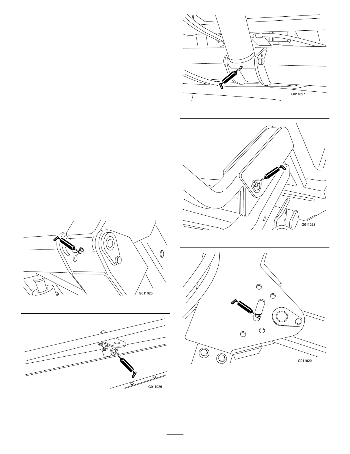
2.Securethehydraulichosesandwiringharnessasshown
inFigure11andFigure12.
1.Cabletie(6)
2.Hoseguide
Figure11
FrontView
7
RoutingandSecuringthe HydraulicHosesandWiring Harness
Partsneededforthisprocedure:
8
Cabletie
Procedure
1.Routethehydraulichosesandwiringharnessthrough
thehoseguidestothefrontofthehitchtongue(Figure
10).
Figure12
RearView
1.Cabletie(2)
13

8
g03051 1
9
ConnectingtheHydraulic
Hoses
NoPartsRequired
Procedure
Connectthehydraulichosesfromthesweepertothequick
couplersonthetowvehicle(Figure13).
Figure13
1.Hydraulichoses2.Harness'
Important:Makesurethatthebrushrotatesinthe
properdirection(whenviewedfromthemotorend,
thebrushshouldrotateclockwise).Ifthebrushis
rotatingcounterclockwise,reversethehydraulichose
connections.
Note:Markthehigh-pressurehosewithacabletieto
identifythecorrecthoseinstallation(Figure14).
ConnectingtheHarness
NoPartsRequired
Procedure
Connecttheharnessfromthesweepertothepowerharness
onthetowvehicle(Figure13).
Note:Ensuretheharnesscannotgetpinchedinthehitch
andensuretheharnessisnotontopoforaroundthehitch
pin.
10
MountingtheWindrowBlades
Partsneededforthisprocedure:
1Blade-mountingassembly
1
Bolt(7/16x3-3/4inch)
1
Bolt(7/16x3-1/4inch)
4
Smallwasher(1/2inch)
1Largewasher
1
Spacer
2
Locknut(7/16inch)
1
Chain
1
Bolt(3/8x1-1/4inch)
1
Flangenut(3/8inch)
1
Snaplink
Procedure
1.Securetheblademountingassemblytotheleftend
ofthesweeperframewithabolt(7/16x3-1/4inch)
bolt,2smallwashers,alargewasher,andalocknut
(7/16inch).
1.Highpressurehose
Figure14
2.Cabletie
Note:PositioncomponentsasshowninFigure15.
2.Securethewindrowbladetothemountingassembly
withabolt(7/16x3-1/4inch),2atwashers,aspacer
andalocknut(7/16inch).Assemblethecomponents
asshowninFigure15.
Note:Positionthelongerendofthebladeawayfrom
thesweeper.
3.Securethechaintotheblademountingassemblywith
abolt(3/8x1-1/4inch)andaangenut(3/8inch)
(Figure15).
14
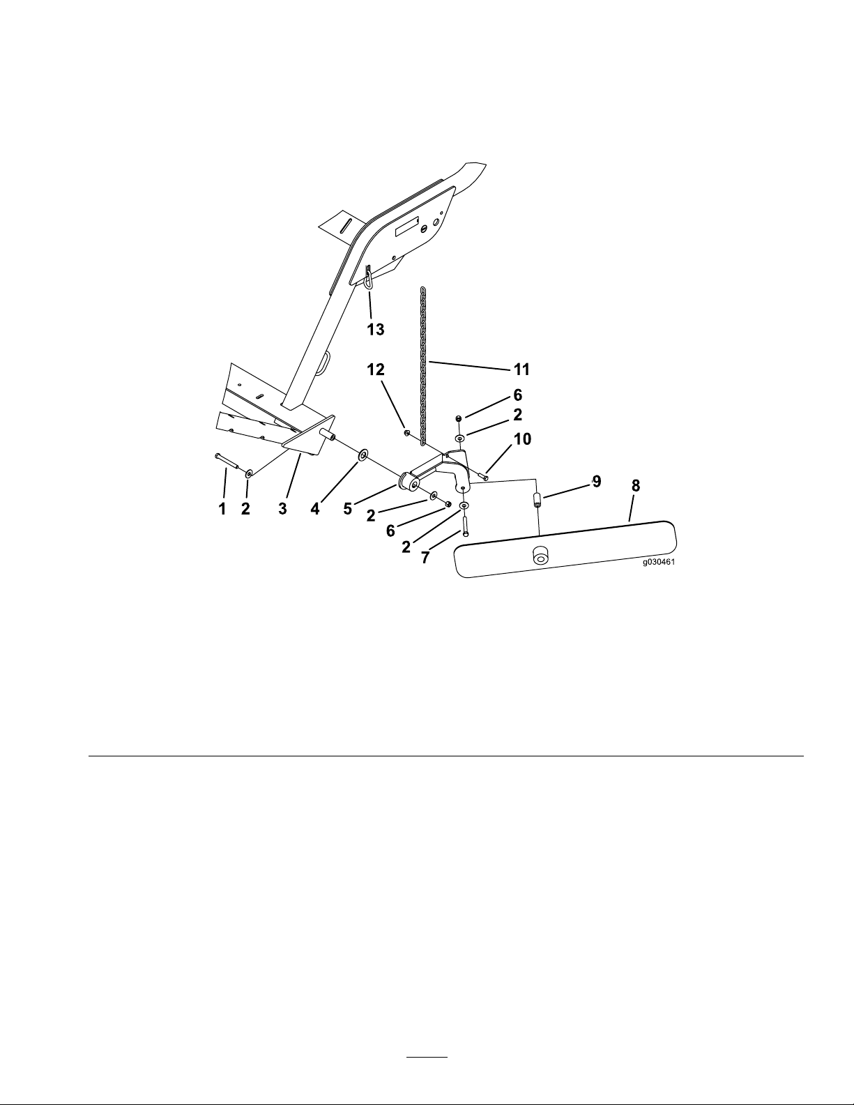
4.Securetheotherendofthechaintotheslotinthe
framewiththesnaplink(Figure15).
Note:Thereshouldbesomeslackinthechainwhen
connected.
5.Greasethettingontheblademountingassemblyand
onthewindrowbladehubwithNo.2lithiumgrease.
Note:Whenthewindrowisnotrequired,unhookthe
chainfromthesnaplink,pivotthewindrowassembly
upward,andhookthechainattheraisedlevel.
Figure15
1.Bolt(7/16x3-3/4inches)
2.Smallwasher(1/2inch)9.Spacer
3.Sweeperframe10.Bolt(3/8x1-1/4inches)
4.Largewasher
5.Blade-mountassembly
6.Locknut(7/16inch)13.Snaplink
7.Bolt(7/16x3-1/4inches)
8.Windrowblade
11.Chain
12.Flangenut(3/8inch)
15

11
AssemblingtheHandheld Remote
Partsneededforthisprocedure:
1Handheldremote
4
Battery(AAA)
6
Screws,small
Procedure
1.Removetherubberbandssecuringtheremotehalves
together,andremovethebackcover.
2.Plugeachbatteryintoaterminalcradleobserving
properpolarity(Figure16).
Note:Ifthebatteriesareimproperlyinstalled,theunit
willnotbedamaged,butitwillfailtooperate.The
cradleisembossedwithpolaritymarkingsforeach
terminal.
Figure16
1.Screw4.Steelgasket
2.Cover
3.Seal
3.Ensurethatthesteelgasketandrubbersealareseated
inthechannelintheremoteandsetthebackcover
inplace(Figure16).
4.Securethecoverwith6screws(Figure16)andtorque
themto1.5to1.7N-m(13to15in-lb).
Note:Donotovertightenthescrews.
5.Batteries
6.Handheldremote
16

ProductOverview
•Transportheight(homeposition)is13–1/4to15–1/4
inches.
Controls
HopperDumpButton
Todumpthehopper,pressthehopperdumpbutton2times
(Figure17).
Important:Thesweepermustbedirectlybehindthe
towvehicleandintransportheightbeforethedump
sequencecanbeactivated.
•Turnaroundheight(off-setposition)is8–1/2to10–1/2
inches.
SweeperUpButton—OptionalMode
Thismodeallowstheoperatortoadjustthesweepertoany
desiredheightanditstopsatthepre-denedheights.
Note:RefertoSwitchingtheSweeper-UpMode(page25)to
switchtotheoptionalmode.
Toraisethesweeperinoptionalmode,pressandholdthe
sweeper-upbuttonuntilthehopperreachesthedesiredheight
orstopsatthepre-denedheight(Figure17).
•Transportheight(homeposition)is13–1/4to15–1/4
inches.
•Turnaroundheight(off-setposition)is8–1/2to10–1/2
inches.
Off-SetLeftButton
Tooff-setthesweepertotheleft,pressandholdtheoff-set
leftbutton(Figure17).Releasingthebuttonwillstopthe
movementtotheleft.
Figure17
1.LEDlight
2.Off-setleft6.Sweeperup
3.Sweeperdown7.Off-setright
4.Hopperdump
5.Stop
SweeperDownButton
Tolowerthehopper,pressthesweeperdownbutton(Figure
17).Thehoppercanbeloweredwhenitisatanyofthe
followingpositions:
•Hopperdumpheight
•Transportheight
•Turnaroundheight
Note:Whenloweringthehopperfromthedump
position,thelowerhopperfunctioncanbestoppedatany
timebyreleasingthesweeper-downbutton.
Note:Withthesweeperinthetransportorturn-around
positions,thelowerhopperfunctioncanbestoppedat
anytimebypressingthesweeperupbutton.
Off-SetRightButton
Tooff-setthesweepertotheright,pressandholdtheoff-set
rightbutton(Figure17).Releasingthebuttonwillstopthe
movementtotheright.
StopButton
Pressingthestopbuttonwilldisableanyactivefunction.
Note:Thereisapproximatelya3seconddelay.
SweeperUpButton—StandardMode
Toraisethesweeperinstandardmode,pressthesweeper-up
button.Thehopperwillstopatthepre-denedheight
(Figure17).
17

DiagnosticLight
Thediagnosticlight(Figure18)islocatedonthefrontcover
andindicatesmachinefaultcodes.Afteryouturnthekey
totheRUNposition,thediagnosticlightwillilluminatefor
5seconds,turnofffor5seconds,andthenbeginashing
3timesaseconduntilyoupushabuttononthehandheld
remote.Ifthelightturnsonfor5secondsandthenstarts
blinking10timesasecond(withorwithouta5secondpause)
thereisafaultwiththemachine;refertoCheckingFault
Codes(page31).
Note:Thediagnosticlightilluminateswhenabuttonis
pushedonthehandheldremote.
Note:Ifyouhaveabuttondepressedonthehandheld
remotewhenyoustartthemachine,thelightwillnotash3
timesasecondafteritturnsofffor5seconds.
Figure18
1.Diagnosticlight
Specications
Note:Specicationsanddesignaresubjecttochange
withoutnotice.
DimensionsandWeights
Width
Height
Dumpheightclearance
LengthHopperlowered-
Emptyweight
Grossvehicleweight(GVW)1588kg(3500lb)
221cm(87inches)
202cm(79-1/2inches)
173cm(68inches)
173cm(68inches)
Hopperraised-229-249
cm(90-98inches)
680kg(1500lb)
Attachments/Accessories
AselectionofToroapprovedattachmentsandaccessoriesis
availableforusewiththemachinetoenhanceandexpand
itscapabilities.ContactyourAuthorizedServiceDealeror
Distributororgotowww .Toro.comforalistofallapproved
attachmentsandaccessories.
18

Operation
Note:Determinetheleftandrightsidesofthemachinefromthenormaloperatingposition.
OperatingtheSweeper
Theprimaryfunctionofthemachineistosweepupdebris
fromlargeturfareas.
Thesweeperisoperatedbyusingtheremotecontrol.Referto
Controls(page17)fortheproperuseofthecontrolbuttons.
Positonthesweeperinthefollowingheightswhen
transportingandturning:
•Transportheight(homeposition)is33.7to38.7cm
(13–1/4to15–1/4inches).
•Turnaroundheight(offsetposition)is21.6to26.7cm
(8–1/2to10–1/2inches).
WARNING
Rotatingpartscancauseseriouspersonalinjury.
•Keephandsandfeetawayfromthesweeperreel
whilethemachineisrunning.
•Keephands,feet,hair,andclothingawayfrom
allmovingpartstopreventinjury.
•Neveroperatethemachinewithcovers,shrouds,
orguardsremoved.
19

AdjustingtheBrushHeight
Adjustthesweepersothebrushtipsslightlytouchthesurfacebutdonotpenetratetheturf.Ifthebrushtipsdopenetrate
theturf,improperdebrispickupcouldresult.
Refertothechartsbelowfortherecommendedsweepersettings.
ConditionRoller/BrushAdjustment
Greens/TeeBoxes2to4notchesfrombottom6to13mm(1/4to1/2inch)
Fairways
Sportselds5to7notchesfrombottom25to76mm(1to3inches)
Leaves
AB
OpenSlots
0
1
2
3
4
5
6
7
8
9
10
11
12
13
3to5notchesfrombottom13to25mm(1/2to1inch)from
5to9notchesfrombottomRemovefrontpanel
TabUp
5.5006.000
5.7506.250
6.0006.500
6.2506.750
6.5007.000
6.7507.250
7.0007.500
7.2507.750
7.5008.000
7.7508.250
8.0008.500
8.2508.750
8.5009.000
8.7509.250
FrontFlapAdjustmentNotes
fromground
ground
fromground
TabDown
5.6256.125
5.8756.375
6.1256.625
6.3756.875
6.6257.125
6.8757.375
7.1257.625
7.3757.875
7.6258.125
7.8758.375
8.1258.625
8.3758.875
8.6259.125
8.8759.375
Brushshouldbeslightly
engagedintheturf
Brushshouldbeengagedinto
thetop1/3ofthegrassheight
Brushshouldbeengagedinto
thetop1/3ofthegrassheight
Brushshouldbeengagedinto
thetop1/3ofthegrassheight
C
20

Figure19
1.“A”4.6to13mm(1/4to1/2inch)
2.“B”
3.“C”
5.Brushdirection
1.Positionthesweeperonalevelsurface.
2.Raisethehopperandinstallthehoppersafetysupport.RefertoUsingtheHopperSafetySupport(page23).
3.Loosenthelocknutontheheightadjustmentkey(Figure20)soitcanbepulledoutapproximately13mm(1/2inch).
Figure20
1.Locknut4.Roller-heightadjustingplat
2.Height-adjustingkey5.Roller-scraperadjustingnuts
3.Roller-heightadjustingnuts
4.Loosentheroller-heightadjustmentlocknuts(Figure20).
5.Pullouttheheight-adjustorkeyandmovetherearrollerupordownbyslidingtheroller-heightadjustingplatetothe
desiredheight(Figure20).
6.Tightenthelocknutssecuringtheadjustment.
7.Repeattheprocedureontheoppositeendofthebrush.Makesurethattheadjustmentsarethesame.
AdjustingtheRollerScraper
Checkandensuretherollerscraper(Figure20)isadjusted
theroller.Loosentherollerscraperadjustingnuts,position
rollerasdesiredandtightenthenuts.
witha2mm(1/16inch)clearancebetweenthescraperand
21

AdjustingtheFrontFlap
CheckingtheWheelLugNut
Height
Forbestdebrispickupresults,adjustthefrontap(Figure
21)witha6mmto13mm(1/4inchto1/2inch)clearance
betweenthebottomoftheapandsurface.
Note:Raisingthefrontapallthewayorremovingthe
frontapmayberequiredwhenpickinguplargerdebrisorif
debrisistobepickedupinlonggrass.
Figure21
1.Frontap
Torque
WARNING
Failuretomaintainpropertorquecouldresultin
failureorlossofwheelandcouldresultinpersonal
injury.
Checkandtorquethewheellugnutsto95-122N-m(70-90
ft-lb).
1.Loosenthenutssecuringthemetalstrapandthefront
aptothebrushhousing(Figure22).
Figure22
1.Frontap
2.Adjustthefrontaptothedesiredoperatingheight
andtightenthenuts.
2.Metalstrap
CheckingtheTirePressure
Figure23
1.Lugnut
ActivatingtheController
Thecontroller(Figure24)isactivatedassoonasyouplugthe
sweeperharnessintothevehiclepowerharness.
•OnWorkmanmodelswithserialnumberspriorto
899999999,theharnesswillhavepower.
•OnWorkmanmodelswithserialnumbers900000001and
up,turntheignitionkeytotheRUNpositiontopower
theharness.
Checkthetirepressuredailytoensuretheyareinated
properly.
Correcttireairpressure:86.2kPa(12-1/2psi.)
Maximumtireairpresssure:of124kPa(18psi)
Note:Thevalvestemislocatedonthebacksideoftherim.
Figure24
1.Controller
22

UsingtheControllerTimeOut
Thesweeperisequippedwithatime-outfeatureforthe
controlmodule.Thetime-outfeatureisactivatedafter2-1/2
hoursofcontinuousremotetransmitterinactivity.
•Wheninthetime-outmodetheremotetransmitterwill
notcontrolanyfunction.
•Towakethecontrollerintime-outmode:
–OnW orkmanmodelswithserialnumberspriorto
899999999,unplugandplugthesweeperharnessinto
thevehiclepowerharness.
–OnWorkmanmodelswithserialnumbers900000001
andup,turntheignitionkeytotheOFFpositionand
backtotheRUNposition.
•Toavoidcontrollertime-outduringoperation,usethe
remotetransmittertooff-setthesweeperatleastevery
2-1/2hours.
Figure26
1.Safetysupport
UsingtheHopperSafety Support
Wheneveryouworkundertheraisedhopper,ensurethat
thehoppersafetysupportisinstalledontotheextendedlift
cylinder.
1.Raisethehopperuntiltheliftcylinderisextended.
2.Removethehairpincotterandpinsecuringthesafety
supporttothestoragebracketonthesweeperframe
(Figure25).Removethesafetysupport.
4.Tostorethesafetysupport,removethesafetysupport
fromthecylinderandsecureittothestoragebracket
onthesweeperframe.
5.Alwaysinstallorremovethesafetysupportfrom
behindthehopper.
6.Donottrytolowerthehopperwiththesafetysupport
onthecylinder.
CheckingtheInterlockSystem
CAUTION
Safetyinterlockswitchesarefortheoperator's
protection.Disconnectedormalfunctioning
safetyinterlockswitchescouldallowthemachine
tooperateinanunsafemannerandmaycause
personalinjury.
•Donotdisconnectthesafetyinterlockswitches.
•Checkoperationoftheswitchesdailytobesure
theinterlocksystemisoperatingcorrectly.
•Ifaswitchismalfunctioning,replaceitbefore
operatingthemachine.
Figure25
1.Hopper-safetysupport
2.Storagebracket
3.Insertthehopper-safetysupportontothecylinderrod,
makingsurethesupportendrestsagainstthecylinder
barrelandthecylinderrodend(Figure26).
Note:Securethehoppersafetysupporttothecylinder
rodwiththehairpincotterandpin.
3.Pin
Thepurposeofthesafetyinterlocksystemisasfollows:
•Preventsthebrushfromrotatingwhenthehopperisin
theraisedposition.
•Preventsthehopperfrombeingdumpedwhenthe
sweeperisintheoffsetposition.
•Audiblealarmwillsoundwhendumpingthehopper.Do
notmovethetowvehiclewhendumpingthehopper.
OperatingTips
•Beforestartingtosweep,surveytheareatodetermine
thebestdirectiontosweep.
23

Note:Tomaintainastraightlinewhensweeping,sight
g030465
anobjectintheforeground.
1.Placethemachineonalevelsurfaceandmakesurethat
itisinthetransportpositionbeforedumping.
•Alwaystrytomakealong,continuousrunwithaslight
overlaponthereturnrun.
•Onturfareas,thebrushwillpickupturfcores,twigs,
clippings,leaves,pineneedlesandcones,andsmalldebris.
•Thesweeperalsogroomstheturf.Thebrushcombs
throughandliftsthegrassforauniformcutwhen
mowed.Asitcleans,thelightscarifyingactionincreases
waterandpesticidepenetration,thusreducingtheneed
forrenovation.
Important:Donotmakesharpturnswhenusing
thesweeperasdamagetotheturfmayoccur.
•Whenthehopperisfull,thesweeperwillnolonger
pickupasefciently,leavingorthrowingmaterialback
ontotheground.
DANGER
Tipovercancauseseriousinjuryordeath.
•Neveroperatethemachineonsteepslopes.
•Sweepslopesupanddown,neveracrossthe
face.
•Whengoinguphillordownhill,donotstopor
startsuddenly .
•Stayalertforholesintheterrainorotherhidden
hazards.Toavoidtippingorlossofcontrol,do
notdriveclosetoaditch,creekordropoff.
2.Pressthehopper-dumpbuttonforonesecond,release
thebuttonforonesecond,andpressthehopper-dump
buttonagain(Figure27).
Note:Thesweeperwillnotrespondifthe
hopper-dumpbuttonispressedtooquickly .
Figure27
1.LEDlight
2.Offsetleft6.Sweeperup
3.Sweeperdown7.Offsetright
4.Hopperdump
5.Stop
•Ifmachinestopsgoinguphill,disengagereels
andbackslowlydownhill.Donotattemptto
turn.
DumpingtheHopper
DANGER
Tipoverorelectricalshockcouldcauseserious
injuryordeath.
•Neverdumpthehopperonaslope.Always
dumpthehopperonlevelground.
•Dumponlyinanareaclearofoverheadwires
andotherobstructions.
Important:Makesurethatthesweeperissecuredto
thetowvehiclehitchwiththehitchpinandtheclevis
pinduringthedumpingoperation.
Important:Ensurethatthesweeperisdirectlybehind
thetowvehicleandintransportheightbeforethedump
sequencecanbeactivated.
Toactivatethedumpsequence:
Figure28
CAUTION
Dumpingthehoppercancauseinjuryto
bystandersorpets.
Keepbystandersandpetsasafedistancefrom
thehopperwhendumpingthehopper.
LoweringtheHopper
Tolowerthehopper,pressthesweeperdownbutton.
Note:Ensurethehopperisinthedownpositionbefore
startingtousethesweeper.
24

InspectingandCleaningthe
g030597
SwitchingtheSweeper-Up
Machine
Whensweepinghasbeencompleted,thoroughlycleanand
washthemachine.Airdrythehopper.Aftercleaning,inspect
themachineforpossibledamagetomechanicalcomponents.
Performingtheseproceduresensuresthatthemachinewill
performsatisfactorilyduringthenextsweepingoperation.
TransportingtheSweeper
•Nevertransportthesweeperwhenthetransportalarm
andthelightareactivated.
•Whentransportingthesweeper,usethetie-downsto
securethefrontofthemachine(Figure29)andtheaxle
(Figure30)tosecuretherearofthemachinetothetrailer.
Note:Transportingthesweeperwithoutusingthe
tie-downscoulddamagethemachine.
Mode
Thesweeper-upbuttonhas2possiblemodes;standardand
optional.
Thestandardmodeallowstheoperatortoraisethesweeper
tothepre-denedheightswithasinglebuttonpush.Referto
SweeperUpButton—StandardMode(page17)
Theoptionalmodeallowstheoperatortoadjustthesweeper
toanydesiredheightanditstopsatthepre-denedheights.
RefertoSweeperUpButton—OptionalMode(page17).
Usethefollowingtoswitchthesweepertotheoptionalmode:
1.Removethecoveroffthecontrolmodule.
2.Unplugthe2wireconnectionsfromthepigtail
connectorshowinFigure31.
3.Plugthe2wireconnectionsintotheexistingpigtail
connectortetheredtothewiringharness.
4.Installthecoverontothecontrolmodule.
Figure29
1.Fronttie-downs
Figure30
1.Reartie-downlocations
OperatingtheMachineinCold Weather
TheWorkmanhighowhydraulicsoilmustreachaoperating
temperatureof82degreesC(180degreesF)forproper
operationoftheoatingsweeperhead.
Figure31
1.Locationofpigtails3.Standard-modepigtail
2.Optional-mode
pigtail—tetheredtothe
wiringhareness
Note:Toreturntostandardmode,installtheoriginal
pigtailconnector.
25

Maintenance
RecommendedMaintenanceSchedule(s)
MaintenanceService
Interval
Aftertherst10hours
Every25hours
Every50hours
Every100hours
Every200hours
Every600hours
MaintenanceProcedure
•T orquethewheellugnuts
•Cleanthereeldrivearea.
•Greasethesweeper.
•Inspecttheconditionofthetires.
•Replacethebrush.
•T orquethewheellugnuts
•Replacethefrontap.
•Inspectthehopperfordamage.
26

DailyMaintenanceChecklist
Duplicatethispageforroutineuse.
Fortheweekof:
MaintenanceCheckItem
Checkthesafetyinterlock
operation.
Checkforunusualoperating
noises.
Checkthetirepressure
Checkhydraulichosesfor
damage
Checkforuidleaks
Checkcontroloperation.
Checkhopper.
Cleanwrappedmaterial
frombrush.
Checkbrushwear .
Lubricateallthegrease
2
ttings
Touch-upanydamaged
paint
1
=.Replaceifmissingorbroken
2
=Immediatelyaftereverywashing,regardlessoftheintervallisted
1
Mon.Tues.Wed.Thurs.Fri.
Sat.Sun.
NotationforAreasofConcern
Inspectionperformedby:
ItemDate
Information
27
Lubrication
ServiceInterval:Every50hours
Thesweeperhas11greasettingsthatrequirelubrication
withNo.2lithiumgrease.Ifthemachineisoperated
undernormalconditions,lubricateallbearingsandbushings
immediatelyaftereverywashing.Lubricatethebearings
andbushingsdailywhenoperatingconditionsareextremely
dustyanddirty.Dustyanddirtyoperatingconditionscould
causedirttogetintothebearingsandbushings,resultingin
acceleratedwear.
1.Lubricatethefollowinggreasettings:
•Hopperpivot(upper)(2)(Figure32).
•Brushpivot(2)(Figure33).
•Liftcylinder(2)(Figure34).
•Hopperpivot(lower)(2)(Figure35).
•Hitchtonguepivot(1)(Figure36).
•Windrowblademount(Figure37).
•Windrowbladehub(Figure37).
2.Wipegreasettingscleansothatforeignmattercannot
beforcedintothebearingorbushing.
3.Pumpgreaseintothebearingorbushing.
4.Wipeupexcessgrease.
Figure34
Figure35
Figure32
Figure33
Figure36
28
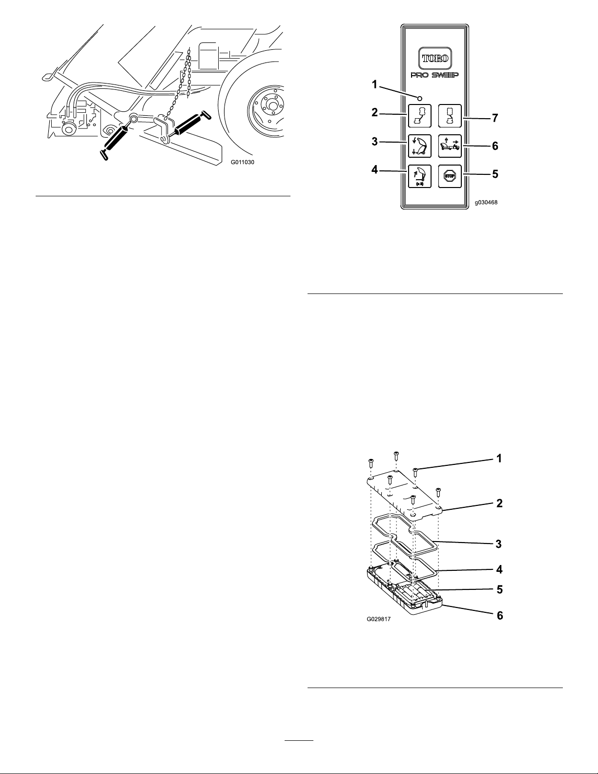
Figure37
AssociatetheRemoteControl andtheBaseUnit
Important:Makesuretoreadtheentireprocedure
beforeattemptingtheassociationprocess.
Theremotecontrolmustestablishcommunicationswith
thebaseunitbeforethesystemcanbeused.Theremote
controlisassociatedtothesystembaseunitbeforeleaving
thefactory.Thisisdoneusingtheassociateprocedure.
Insituationswhereitisnecessarytore-establishremote
control-to-baseunitcommunications(example:introducing
aneworspareremotecontroltoanexistingbaseunit),the
followingassociateproceduremustbeperformed.
Note:Associatingtheremotecontroltoadifferentbase
unitwilldisassociatethatremotecontrolfromtheoriginal
baseunit.
1.Removepowerfromthebaseunit.
2.Standnearthebaseunitinunobstructed,clear
line-of-sightwiththeremotecontrolinhand.
3.SimultaneouslypressandholdtheOFF-SETLEFTand
OFF-SETRIGHTbuttons.TheLEDwillblinkabout
oncepersecond.
Figure38
1.LEDlight
2.Off-setleft6.Sweeperup
3.Sweeperdown7.Off-setright
4.Hopperdump
5.Stop
ReplacingtheRemote Batteries
Thehandheldremoteispoweredby4AAAbatteries.When
installingbatteries,observeproperpolarityasmarkedonthe
insideofthecompartmenttoavoiddamagingtheunit.
1.Removethe6screwsfromthebackoftheremoteand
removethecover(Figure39).
Note:Ifpossible,leavetherubbersealandsteelgasket
inthechannelwhenremovingthecoverandbatteries.
4.ContinuetoholdbothbuttonsuntiltheLEDbegins
blinkingabouttwicepersecond.
5.Releasethebuttons.
6.PressandholdtheOFF-SETLEFTbutton.TheLED
willblinkabouttwicepersecond.
7.ContinueholdingtheOFF-SETLEFTbuttonandturn
thekeystarttotheRUNposition.TheLEDwillturn
solidiftheprocedureissuccessful.
Note:Thiscouldtakeupto20seconds.
8.ReleasetheOFF-SETLEFTbutton.
Thesystemisreadyforusewiththatparticularremote
control.
Figure39
1.Screw4.Steelgasket
2.Cover
3.Seal
2.Removethedischargedbatteriesandproperlydispose
inaccordancewithlocalregulations.
29
5.Batteries
6.Handheldremote

3.Plugeachfreshbatteryintoaterminalcradleobserving
properpolarity.
Storage
Note:Ifthebatteriesareimproperlyinstalled,theunit
willnotbedamaged,butitwillfailtooperate.
4.Ifyouaccidentallyremovedtherubbersealandthe
steelgasket,replacethemcarefullyintothechannelin
thehandheldremote.
5.Replacethecoverandsecureitwiththe6screws
removedpreviously(Figure39)andtorquethemto1.5
to1.7N-m(13to15in-lb).
Note:Donotover-tightenthescrews.
1.Thoroughlycleanthesweepersoitisfreeofdirt,leaves
anddebris.
2.Checkthetirepressure.RefertoCheckingtheTire
Pressure(page22).
3.Checkallfasteners.Tightenasnecessary.
4.Greaseallgreasettings.Wipeoffexcesslubricant.
5.Checktheconditionofthebrush.Replaceasrequired.
30

Troubleshooting
ConditionPossibleCausesCorrectiveAction
Thesweeperisnot
pickingupdebris.
Thebrushisdamaged.
Thebrushheightistoohigh.
Replacebrush.
Adjustbrushheight.SeeBrushHeightAdjustment.
Thesweeperhas
excessivevibration.
Thediagnosticlighton
thesweeperdoesnot
illuminatewhenpressing
aremotebutton.
TheFrontapheightistoolowortoohigh.
Checkthebearingsonthebrushshaft.Iftheyare
excessivelyhot,checkthebearingsfordamage.
Foreignmaterialsarewrappedaroundbrush.
Thereisfrequencyinterference.Associatetheremotecontroltothebaseunit.Refer
Adjustfrontapheight.SeeFrontFlapAdjustment
Replaceanydamagedbearings.
Cleanoffanyforeignobjects.
toAssociatetheRemoteControlandtheBaseUnit
(page29).
CheckingFaultCodes
Ifthediagnosticlightindicatesthatthereisasystemfault(referto(page)),checkthefaultcodestodetermine
whatiswrongwiththemachine.
31

EnteringDiagnosticModeandCheckingtheCodes
1.TurnthekeytotheRUNposition.
2.Disconnectthepowerbyseparatingthevehicleharnessfromthesweeperharness.
3.Removethefrontcover.
4.Pullthetetheredcapoffthe2diagnostic,shuntconnectors(Figure40,A).
5.Connectthediagnostic,shuntconnectorstogether(Figure40,B).
Figure40
6.Connectthevehicleandsweeperwireharnesstogethertopowerthesweeper.
7.Countthenumberofashestodeterminethefaultcode,thenconsultthefollowingtable:
Note:Iftherearemultiplefaults,bothfaultswillash,thenalongpause,thentheashsequenceswillrepeat.
Code
11Blinkonce,pause,blinkonce,
12Blinkonce,pause,blinktwice,
13Blinkonce,pause,blink3
LEDFlashPatternBehaviorDetails
MachineSpecicFaults
longpause,thenrepeat
longpause,thenrepeat
times,longpause,thenrepeat
Lostcommunicationwith
BASE.
Versionincompatibilityofthe
BASEand/orHH
WrongHH—notimplemented
onRevA
8.Installthefrontcover.
Connectornotplugged
in;locatethelooseor
disconnectedharness
connectorandconnectit.
Somethingwronginthewiring;
contactyourToroDistributor.
BASEisbad;contactyourToro
Distributor.
Wrongsoftware(install
thecorrectsoftwarefrom
TORODIAG);contactyourToro
Distributor.
Wrongproductassociation
(i.e.tryingtoupdatesoftware
onaMH–400withaProPass
handheld)
32

ResettingtheFaultCodes
Aftersolvingtheproblem,disconnectandreconnectthediagnosticconnectors.Thediagnosticlightwillash
continuouslyoncepersecond.
ExitingDiagnosticMode
1.TurnthekeytotheRUNposition.
2.Disconnectthepowerbyseparatingthevehicleharnessfromthesweeperharness.
3.Disconnectthediagnostic,shuntconnectors.
4.Pushthetetheredcapontothe2diagnostic,shuntconnectors.
5.Connectthevehicleandsweeperwiringharnesstogethertopowerthesweeper.
33

Notes:
34

InternationalDistributorList
Distributor:
AgrolancKft
BalamaPrimaEngineeringEquip.HongKong85221552163
B-RayCorporation
CascoSalesCompany
CeresS.A.CostaRica
CSSCTurfEquipment(pvt)Ltd.SriLanka
CyrilJohnston&Co.
CyrilJohnston&Co.RepublicofIreland
EquiverMexico525553995444ParklandProductsLtd.NewZealand6433493760
FemcoS.A.Guatemala
ForGarderOU
G.Y .K.CompanyLtd.
GeomechanikiofAthensGreece
GolfinternationalTurizm
GuandongGoldenStarChina
HakoGroundandGardenSweden
HakoGroundandGarden
HayterLimited(U.K.)
HydroturfInt.CoDubai
HydroturfEgyptLLC
IrrimacPortugal351212388260ToroEuropeNVBelgium3214562960
IrrigationProductsInt'lPvtLtd.India0091442449
JeanHeybroekb.v.Netherlands3130639461 1VictusEmakPoland48618238369
Country:
Hungary3627539640
Korea82325512076
PuertoRico7877888383
NorthernIreland442890813121
Estonia3723846060
Japan81726325861
Turkey902163365993Riversa
Norway4722907760
UnitedKingdom441279723444
UnitedArabEmirates97143479479T-MarktLogisticsLtd.Hungary3626525500
Egypt2025194308ToroAustraliaAustralia61395807355
PhoneNumber:Distributor:
5062391138
94112746100
442890813121
5024423277
30109350054
862087651338
4635100000
4387
Country:
MaquiverS.A.Colombia
MaruyamaMfg.Co.Inc.
Mountelda.s.CzechRepublic
Mountelda.s.Slovakia
MunditolS.A.
NormaGarden
OslingerTurfEquipmentSA
OyHakoGroundandGarden
Ab
Perfetto
PratoverdeSRL.
Prochaska&Cie
RTCohen2004Ltd.
LelyTurfcare
SolvertS.A.S.
SpyprosStavrinidesLimitedCyprus
SurgeSystemsIndiaLimited
ValtechMorocco21253766
Japan81332522285
Argentina54114821
Russia749541 16120
Ecuador59342396970
Finland35898700733
Poland48618208416
Italy390499128
Austria4312785100
Israel97298617979
Spain
Denmark4566109200
France331308177
India911292299901
Phone
Number:
5712364079
420255704
220
420255704
220
9999
128
34952837500
00
35722434131
3636
EuropeanPrivacyNotice
TheInformationToroCollects
ToroWarrantyCompany(T oro)respectsyourprivacy .Inordertoprocessyourwarrantyclaimandcontactyouintheeventofaproductrecall,weaskyou
tosharecertainpersonalinformationwithus,eitherdirectlyorthroughyourlocalT orocompanyordealer.
TheT orowarrantysystemishostedonserverslocatedwithintheUnitedStateswhereprivacylawmaynotprovidethesameprotectionasapplies
inyourcountry.
BYSHARINGYOURPERSONALINFORMATIONWITHUS,YOUARECONSENTINGTOTHEPROCESSINGOFYOURPERSONALINFORMATION
ASDESCRIBEDINTHISPRIV ACYNOTICE.
TheWayT oroUsesInformation
Toromayuseyourpersonalinformationtoprocesswarrantyclaims,tocontactyouintheeventofaproductrecallandforanyotherpurposewhichwetell
youabout.ToromayshareyourinformationwithT oro'safliates,dealersorotherbusinesspartnersinconnectionwithanyoftheseactivities.Wewillnot
sellyourpersonalinformationtoanyothercompany.Wereservetherighttodisclosepersonalinformationinordertocomplywithapplicablelawsand
withrequestsbytheappropriateauthorities,tooperateoursystemsproperlyorforourownprotectionorthatofotherusers.
RetentionofyourPersonalInformation
Wewillkeepyourpersonalinformationaslongasweneeditforthepurposesforwhichitwasoriginallycollectedorforotherlegitimatepurposes
(suchasregulatorycompliance),orasrequiredbyapplicablelaw .
Toro'sCommitmenttoSecurityofY ourPersonalInformation
Wetakereasonableprecautionsinordertoprotectthesecurityofyourpersonalinformation.Wealsotakestepstomaintaintheaccuracyandcurrent
statusofpersonalinformation.
AccessandCorrectionofyourPersonalInformation
Ifyouwouldliketorevieworcorrectyourpersonalinformation,pleasecontactusbyemailatlegal@toro.com.
AustralianConsumerLaw
AustraliancustomerswillnddetailsrelatingtotheAustralianConsumerLaweitherinsidetheboxoratyourlocalT oroDealer.
374-0269RevH

ToroGeneralCommercialProductWarranty
ATwo-YearLimitedWarranty
ConditionsandProductsCovered
TheToroCompanyanditsafliate,ToroWarrantyCompany,pursuant
toanagreementbetweenthem,jointlywarrantyourT oroCommercial
product(“Product”)tobefreefromdefectsinmaterialsorworkmanship
fortwoyearsor1500operationalhours*,whicheveroccursrst.This
warrantyisapplicabletoallproductswiththeexceptionofAerators
(refertoseparatewarrantystatementsfortheseproducts).Wherea
warrantableconditionexists,wewillrepairtheProductatnocosttoyou
includingdiagnostics,labor,parts,andtransportation.Thiswarranty
beginsonthedatetheProductisdeliveredtotheoriginalretailpurchaser.
*Productequippedwithanhourmeter.
InstructionsforObtainingWarrantyService
YouareresponsiblefornotifyingtheCommercialProductsDistributoror
AuthorizedCommercialProductsDealerfromwhomyoupurchasedthe
Productassoonasyoubelieveawarrantableconditionexists.Ifyouneed
helplocatingaCommercialProductsDistributororAuthorizedDealer,or
ifyouhavequestionsregardingyourwarrantyrightsorresponsibilities,
youmaycontactusat:
ToroCommercialProductsServiceDepartment
ToroWarrantyCompany
811 1LyndaleAvenueSouth
Bloomington,MN55420-1196
952–888–8801or800–952–2740
E-mail:commercial.warranty@toro.com
OwnerResponsibilities
AstheProductowner,youareresponsibleforrequiredmaintenanceand
adjustmentsstatedinyourOperator'sManual.Failuretoperformrequired
maintenanceandadjustmentscanbegroundsfordisallowingawarranty
claim.
ItemsandConditionsNotCovered
Notallproductfailuresormalfunctionsthatoccurduringthewarranty
periodaredefectsinmaterialsorworkmanship.Thiswarrantydoesnot
coverthefollowing:
•Productfailureswhichresultfromtheuseofnon-T ororeplacement
parts,orfrominstallationanduseofadd-on,ormodiednon-Toro
brandedaccessoriesandproducts.Aseparatewarrantymaybe
providedbythemanufactureroftheseitems.
•Productfailureswhichresultfromfailuretoperformrecommended
maintenanceand/oradjustments.Failuretoproperlymaintainyour
ToroproductpertheRecommendedMaintenancelistedinthe
Operator’sManualcanresultinclaimsforwarrantybeingdenied.
•ProductfailureswhichresultfromoperatingtheProductinanabusive,
negligent,orrecklessmanner.
•Partssubjecttoconsumptionthroughuseunlessfoundtobedefective.
Examplesofpartswhichareconsumed,orusedup,duringnormal
Productoperationinclude,butarenotlimitedto,brakepadsand
linings,clutchlinings,blades,reels,rollersandbearings(sealedor
greasable),bedknives,sparkplugs,castorwheelsandbearings,tires,
lters,belts,andcertainsprayercomponentssuchasdiaphragms,
nozzles,andcheckvalves,etc.
•Failurescausedbyoutsideinuence.Conditionsconsideredtobe
outsideinuenceinclude,butarenotlimitedto,weather,storage
practices,contamination,useofunapprovedfuels,coolants,lubricants,
additives,fertilizers,water,orchemicals,etc.
•Failureorperformanceissuesduetotheuseoffuels(e.g.gasoline,
diesel,orbiodiesel)thatdonotconformtotheirrespectiveindustry
standards.
•Normalnoise,vibration,wearandtear ,anddeterioration.
•Normal“wearandtear”includes,butisnotlimitedto,damagetoseats
duetowearorabrasion,wornpaintedsurfaces,scratcheddecalsor
windows,etc.
Parts
Partsscheduledforreplacementasrequiredmaintenancearewarranted
fortheperiodoftimeuptothescheduledreplacementtimeforthatpart.
Partsreplacedunderthiswarrantyarecoveredforthedurationofthe
originalproductwarrantyandbecomethepropertyofT oro.T orowillmake
thenaldecisionwhethertorepairanyexistingpartorassemblyorreplace
it.T oromayuseremanufacturedpartsforwarrantyrepairs.
DeepCycleandLithium-IonBatteryWarranty:
DeepcycleandLithium-Ionbatterieshaveaspeciedtotalnumberof
kilowatt-hourstheycandeliverduringtheirlifetime.Operating,recharging,
andmaintenancetechniquescanextendorreducetotalbatterylife.Asthe
batteriesinthisproductareconsumed,theamountofusefulworkbetween
chargingintervalswillslowlydecreaseuntilthebatteryiscompletelyworn
out.Replacementofwornoutbatteries,duetonormalconsumption,
istheresponsibilityoftheproductowner.Batteryreplacementmaybe
requiredduringthenormalproductwarrantyperiodatowner’sexpense.
Note:(Lithium-Ionbatteryonly):ALithium-Ionbatteryhasapartonly
proratedwarrantybeginningyear3throughyear5basedonthetime
inserviceandkilowatthoursused.RefertotheOperator'sManualfor
additionalinformation.
MaintenanceisatOwner’sExpense
Enginetune-up,lubrication,cleaningandpolishing,replacementoflters,
coolant,andcompletingrecommendedmaintenancearesomeofthe
normalservicesT oroproductsrequirethatareattheowner’sexpense.
GeneralConditions
RepairbyanAuthorizedToroDistributororDealerisyoursoleremedy
underthiswarranty.
NeitherTheToroCompanynorToroWarrantyCompanyisliablefor
indirect,incidentalorconsequentialdamagesinconnectionwiththe
useoftheToroProductscoveredbythiswarranty,includingany
costorexpenseofprovidingsubstituteequipmentorserviceduring
reasonableperiodsofmalfunctionornon-usependingcompletion
ofrepairsunderthiswarranty.ExceptfortheEmissionswarranty
referencedbelow,ifapplicable,thereisnootherexpresswarranty.All
impliedwarrantiesofmerchantabilityandtnessforusearelimitedto
thedurationofthisexpresswarranty.
Somestatesdonotallowexclusionsofincidentalorconsequential
damages,orlimitationsonhowlonganimpliedwarrantylasts,sotheabove
exclusionsandlimitationsmaynotapplytoyou.Thiswarrantygivesyou
speciclegalrights,andyoumayalsohaveotherrightswhichvaryfrom
statetostate.
Noteregardingenginewarranty:
TheEmissionsControlSystemonyourProductmaybecoveredby
aseparatewarrantymeetingrequirementsestablishedbytheU.S.
EnvironmentalProtectionAgency(EP A)and/ortheCaliforniaAirResources
Board(CARB).Thehourlimitationssetforthabovedonotapplytothe
EmissionsControlSystemWarranty.RefertotheEngineEmissionControl
WarrantyStatementsuppliedwithyourproductorcontainedintheengine
manufacturer’sdocumentationfordetails
CountriesOtherthantheUnitedStatesorCanada
CustomerswhohavepurchasedT oroproductsexportedfromtheUnitedStatesorCanadashouldcontacttheirT oroDistributor(Dealer)toobtain
guaranteepoliciesforyourcountry ,province,orstate.IfforanyreasonyouaredissatisedwithyourDistributor'sserviceorhavedifcultyobtaining
guaranteeinformation,contacttheT oroimporter.
374-0253RevC
 Loading...