

Page 1

FormNo.3370-794RevA
66inRake-O-Vac
ModelNo.07050—SerialNo.312000001andUp
®
Sweeper
ToregisteryourproductordownloadanOperator'sManualorPartsCatalogatnocharge,gotowww.T oro.com.OriginalInstructions(EN)
Page 2
ThisproductcomplieswithallrelevantEuropean
g015255
1
directives,fordetailspleaseseetheseparateproduct
specicDeclarationofConformity(DOC)sheet.
WARNING
CALIFORNIA
Proposition65Warning
Theengineexhaustfromthisproduct
containschemicalsknowntotheStateof
Californiatocausecancer,birthdefects,
orotherreproductiveharm.
ThissparkignitionsystemcomplieswithCanadian
ICES-002.
Important:Thisengineisnotequippedwitha
sparkarrestermufer.ItisaviolationofCalifornia
PublicResourceCodeSection4442touseoroperate
theengineonanyforest-covered,brush-covered,or
grass-coveredland.Otherstatesorfederalareas
mayhavesimilarlaws.
Introduction
Readthisinformationcarefullytolearnhowtooperate
andmaintainyourproductproperlyandtoavoidinjury
andproductdamage.Youareresponsibleforoperating
theproductproperlyandsafely.
YoumaycontactTorodirectlyatwww .Toro.comfor
productandaccessoryinformation,helpndingadealer,
ortoregisteryourproduct.
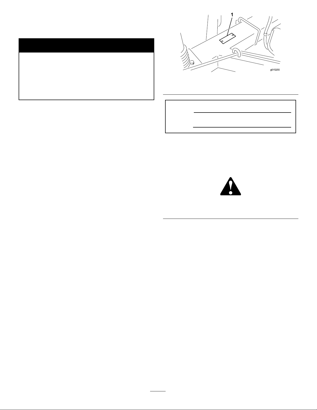
Figure1
1.Locationofthemodelandserialnumbers
ModelNo.
SerialNo.
Thismanualidentiespotentialhazardsandhassafety
messagesidentiedbythesafetyalertsymbol(Figure2),
whichsignalsahazardthatmaycauseseriousinjury
ordeathifyoudonotfollowtherecommended
precautions.
Figure2
1.Safetyalertsymbol
Thismanualuses2otherwordstohighlightinformation.
Importantcallsattentiontospecialmechanical
informationandNoteemphasizesgeneralinformation
worthyofspecialattention.
Wheneveryouneedservice,genuineToroparts,
oradditionalinformation,contactanAuthorized
ServiceDealerorToroCustomerServiceandhave
themodelandserialnumbersofyourproductready.
Figure1illustratesthelocationofthemodelandserial
numbersontheproduct.Writethenumbersinthe
spaceprovided.
©2012—TheT oro®Company
8111LyndaleAvenueSouth
Bloomington,MN55420
Contactusatwww.Toro.com.
2
PrintedintheUSA.
AllRightsReserved
Page 3

Contents
Introduction.................................................................2
Safety...........................................................................4
SafeOperatingPractices.......................................4
SafetyandInstructionalDecals.............................6
Setup...........................................................................8
1ActivatingandChargingtheBattery....................8
2MounttheSweepertothePrime
Mover..............................................................9
3RemovingSweeperfromthePrime
Mover............................................................10
ProductOverview......................................................11
Controls.............................................................11
Specications.....................................................12
Operation...................................................................12
AddingFuel.......................................................12
CheckingtheEngineOilLevel............................13
StartingandStoppingtheEngine........................13
TransportingtheMachine...................................14
AdjustingtheRakeDepth...................................14
AdjusttheRubberFlap.......................................14
InspectandCleanupafterOperation...................15
OperatingTips...................................................15
Maintenance...............................................................16
RecommendedMaintenanceSchedule(s)................16
Lubrication.............................................................17
Lubrication.........................................................17
OiltheSweeperJack...........................................17
EngineMaintenance...............................................18
ServicingtheAirCleaner....................................18
ChangingtheEngineOilandFilter.....................18
ServicingtheSparkPlugs....................................19
RemoveDebrisfromtheEngine.........................19
FuelSystemMaintenance.......................................20
ReplacingtheFuelFilter.....................................20
ElectricalSystemMaintenance................................20
ServicingtheBattery...........................................20
DriveSystemMaintenance.....................................21
TireMaintenance................................................21
BeltMaintenance....................................................22
InspectingtheBelts............................................22
AdjustingtheBelts.............................................23
ChangingtheRubberFlap......................................24
PulleyRemoval.......................................................24
FlexTipReelRemoval............................................25
FlexTipRakeRodOrFingerPlate
Replacement...................................................25
FlexTipRakeTineReplacement.............................26
BrushHalfReplacement.........................................26
Cleaning.................................................................27
CleaningtheBlowerHousing..............................27
Storage.......................................................................27
3
Page 4

Safety
Improperuseormaintenancebytheoperator
orownercanresultininjury.Toreducethe
potentialforinjury,complywiththesesafety
instructionsandalwayspayattentiontothesafety
alertsymbol,whichmeans
Danger
complywiththeinstructionmayresultinpersonal
injuryordeath.
—personalsafetyinstruction.Failureto
SafeOperatingPractices
Caution
,
W ar ning
Preparation
•Evaluatetheterraintodeterminewhataccessories
andattachmentsareneededtoproperlyand
safelyperformthejob.Onlyuseaccessoriesand
attachmentsapprovedbythemanufacturer.
,or
•Weartheappropriateclothingincludingahardhat,
safetyglasses,andhearingprotection.Longhair,
looseclothing,orjewelrymaygettangledinmoving
parts.
•Useextracarewhenhandlinggasolineandother
fuels.Theyareammableandthevaporsare
explosive.
Training
•ReadtheOperator’sManualandothertraining
material.Iftheoperator(s)ormechanic(s)cannot
readEnglishitistheowner’sresponsibilitytoexplain
thismaterialtothem.
•Becomefamiliarwiththesafeoperationofthe
equipment,operatorcontrols,andsafetysigns.
•Alloperatorsandmechanicsshouldbetrained.The
ownerisresponsiblefortrainingtheusers.
•Neverletchildrenoruntrainedpeopleoperateor
servicetheequipment.Localregulationsmayrestrict
theageoftheoperator.
•Theowner/usercanpreventandisresponsiblefor
accidentsorinjuriesoccurringtohimselforherself,
otherpeopleorproperty.
•Themachinemustbetowedtooperate,itis
extremelyimportantthatthetowtractorbecarefully
selectedtoassurethebestperformanceandsafe
operation.
•Thetowtractormusthavetheproperwheelbase,
treadwidth,workingseatbelt,andmustbeequipped
witharollbartooperatesafelyonhillyterrain.
Thenormaloperatingspeedis6MPH(9km/h)
butwillvarywithterrainanddebrisbeingpicked
up.Themaximumtransportspeedis20MPH(32
km/h)withslowerspeedsrequiredonhillyterrain.
RefertotractorOperator’sManualforinformationor
tractorserviceagencyifyouhaveanyquestionon
safeoperation.
•Thebrakesofthetowtractormusthavethecapacity
tostopthemachinewithhopperfullyloadedand
travelingatthemaximumrecommendedtransport
speed.
•Ensurethatthemachinecomplieswithlocalroad
requirementswhenbeingtransportedonpublic
roads.Aslowmovingvehiclesignhasbeenprovided.
Signallightsandbrakesarenotprovidedandmay
berequiredinsomeareas.
–Useonlyanapprovedcontainer.
–Neverremovethegascaporaddfuelwiththe
enginerunning.
–Allowtheenginetocoolbeforerefueling.
–Donotsmokewhenhandlinggasolineandother
fuels.
–Neverrefuelordrainthemachineindoors.
•Checkthattheoperatorpresencecontrols,safety
switches,andshieldsareattachedandfunctioning
properly.Donotoperateunlesstheyarefunctioning
properly.
•Keepallshields,safetydevices,anddecalsinplace.
Ifashield,safetydevice,ordecalismalfunctioning,
illegible,ordamaged,replaceitbeforeoperatingthe
machine.
Operation
•Neverrunanengineinanenclosedarea.
•Onlyoperateingoodlight,keepingawayfromholes
andhiddenhazards.
•Besurealldrivesareinneutralandparkingbrakeis
engagedbeforestartingengine.Starttheengineonly
fromtheoperator’sposition.
•Neveroperatewithouttheshields,covers,orother
guardssecurelyinplace.Besureallinterlocksare
functioningproperly .
•Stoponalevelground,emptythehopper,andblock
thewheelsbeforeremovingthesweeperfromthe
primemover.
•Shuttheengineoffandwaitforallmovementto
stop.Theimpellermaymomentarilyturnafterother
componentshavestopped.Useextremecaution
whenremovingthecoverfromtheblowerhousing.
•Keephandsandfeetawayfromthesweeperarea.
•Nevercarrypassengers.Keeppetsandbystanders
away.
4
Page 5

•Bealert,slowdown,andusecautionwhenmaking
turns.Lookbehindandtothesideofthemachine
beforechangingdirections.
•Beforebackingup,looktotherearofthemachine
andensurethatnooneisbehindthemachine.
•Slowdownandusecautionwhencrossingroads
andsidewalks.
MaintenanceandStorage
•Disengagethepowertothemachine,stopthe
engine,andwaitforallmovementtostopbefore
adjusting,cleaning,repairing,ortransporting.
•Cleanthegrassanddebrisfromtheraketines,drives,
mufers,andenginetohelppreventres.Cleanup
anyoilorfuelspillage.
•Donotoperatethemachineundertheinuenceof
alcoholordrugs.
•Lightningcancausesevereinjuryordeath.If
lightningisseen,orthunderisheardinthearea,do
notoperatethemachine;seekshelter.
•Usecarewhenapproachingblindcorners,shrubs,
trees,orotherobjectsthatmayobscurevision.
•Useextremecautionaroundditches,creeks,orother
hazards.
•Avoidsuddenstopsandstarts.
•Ifthemachinevibratesabnormally,stopimmediately ,
turntheengineoff,waitforallmotiontostop,and
inspectfordamage.Repairallofthedamagebefore
operation.
•Shutthesweeperbloweroffwhendumpingthe
contentsofthehopper.Alwaysstandtotheextreme
rightorleftsideofthehopperwhenopeningthe
tailgate.
SlopeOperation
•Donotoperateneardrop-offs,ditches,steepbanks,
orwater.Wheelsdroppingoveredgescancause
rollovers,whichmayresultinseriousinjuryordeath.
•Donotoperateonslopeswhengrassiswet.Slippery
conditionsreducetractionandcouldcausesliding
andlossofcontrol.
•Donotmakesuddenturnsorrapidspeedchanges.
•Reducespeedanduseextremecautiononslopes.
•Removeormarkobstaclessuchasrocks,treelimbs,
etc.fromtheoperatingarea.Tallgrasscanhide
obstacles.
•Lettheenginecoolbeforestoringanddonotstore
nearame.
•Shutoffthefuelwhilestoringortransportingon
trailers.Donotstorethefuelnearamesordrain
indoors.
•Disconnectthebatteryorremovethesparkplug
wiresbeforemakinganyrepairs.Disconnectthe
negativeterminalrstandthepositiveterminallast.
Reconnectthepositiveterminalrstandthenegative
terminallast.
•Keephandsandfeetawayfromanymovingparts.If
possible,donotmakeadjustmentswiththeengine
running.
•Donotoverspeedtheenginebychangingthe
governorsettings.Toensuresafetyandaccuracy,
haveanauthorizedT orodistributorcheckthe
maximumenginespeedwithatachometer.
•Lettheenginecoolbeforecheckingtheoiloradding
oiltothecrankcase.
•Checktheprimemoverbrakesandallsafety
equipmentperiodically .
•Chargethebatteryinanopen,wellventilatedarea,
awayfromsparkandames.Unplugthecharger
beforeconnectingordisconnectingitfromthe
battery.Wearprotectiveclothinganduseinsulated
tools.
•Keepallofthepartsingoodworkingconditionand
allhardwaretightened.Replaceallofthewornor
damageddecals.
•UseonlyToro-approvedattachments.The
warrantymaybevoidedifthemachineisusedwith
unapprovedattachments.
•Watchforditches,holes,rocks,dips,andrisesthat
changetheoperatingangle,asroughterraincould
overturntheaerator.
•Alwaysavoidsuddenstartingorstoppingonaslope.
Iftireslosetraction,disengagethetinesandproceed
slowlyofftheslope.
•Followtherecommendationsforwheelweightsor
counterweightstoimprovestability.
5
Page 6
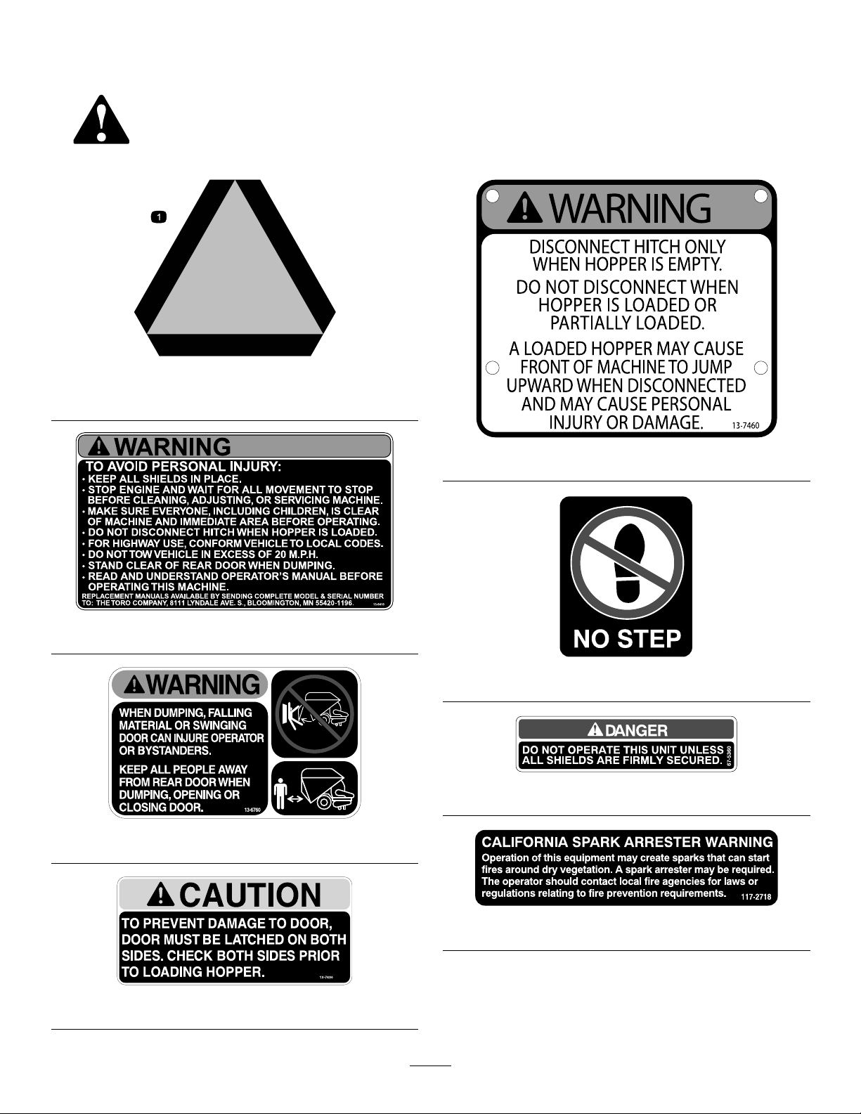
SafetyandInstructionalDecals
Safetydecalsandinstructionsareeasilyvisibletotheoperatorandarelocatednearanyareaof
potentialdanger.Replaceanydecalthatisdamagedorlost.
13-2930
1.Slowmovingvehiclesymbol
13–7460
13–6410
61-5950
67-5360
13-6760
117–2718
13-7430
6
Page 7
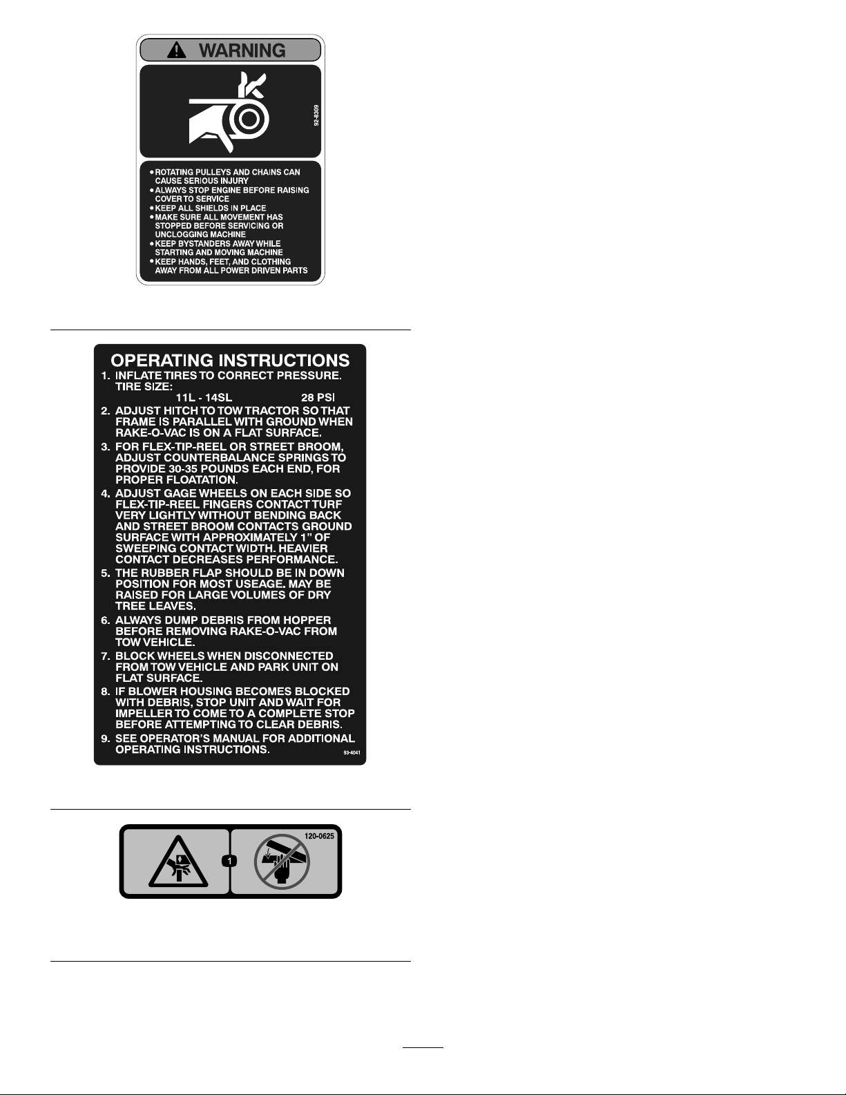
92-8309
93-4041
120-0625
1.Pinchpoint,hand—keephandsaway .
7
Page 8

Setup
LooseParts
Usethechartbelowtoverifythatallpartshavebeenshipped.
ProcedureDescription
1
2
3
Nopartsrequired
Bolts2
Locknuts2
Nopartsrequired
MediaandAdditionalParts
Description
Operator'sManual
EngineOperator'sManual
PartsCatalog
Note:Determinetheleftandrightsidesofthemachine
fromthenormaloperatingposition.
1
ActivatingandChargingthe
Qty.
1
1
1Viewandorderparts.
Readbeforeoperatingthemachine.
4.Carefullylleachcellwithelectrolyteuntilthe
electrolyteisuptothellline.
Useonlyelectrolyte(1.260SpecicGravity)toll
thebatteryinitially.
Important:Donotaddelectrolytewhilethe
batteryisinthemachine.Y oucouldspillit,
causingcorrosion.
Qty.
Use
–
–
Activateandchargethebattery.
Mountsweepertoprimemover.
Removingsweeperfromprimemover.
Use
Battery
NoPartsRequired
Procedure
WARNING
CALIFORNIA
Proposition65Warning
Batteryposts,terminals,andrelated
accessoriescontainleadandleadcompounds,
chemicalsknowntotheStateofCalifornia
tocausecancerandreproductiveharm.
Washhandsafterhandling.
1.Unlatchandopenthebatterycompartmentcover.
2.Removethebatteryfromthebatterycompartment.
3.Cleanthetopofthebatteryandremovethevent
caps.
DANGER
Batteryelectrolytecontainssulfuricacidwhich
isadeadlypoisonandcausessevereburns.
•Donotdrinkelectrolyteandavoidcontact
withskin,eyes,orclothing.Wearsafety
glassestoshieldyoureyesandrubbergloves
toprotectyourhands.
•Fillthebatterywherecleanwaterisalways
availableforushingtheskin.
5.Connecta3to4ampbatterychargertothebattery
posts.Chargethebatteryatarateof3to4amps
for4to8hours.
6.Removethellercapsandslowlyaddelectrolyteto
eachcelluntilthelevelisuptothellline.Install
thellercaps.
Important:Donotoverllthebattery.
Electrolytewilloverowontootherpartsofthe
machineandseverecorrosionanddeterioration
willresult.
8
Page 9

WARNING
Chargingthebatteryproducesgassesthatcan
explode.
Neversmokenearthebatteryandkeepsparks
andamesawayfromthebattery.
7.Whenthebatteryischarged,disconnectthecharger
fromtheelectricaloutletandbatteryposts.Allowthe
batterytositfor5to10minutesbeforeproceeding
tothenextstep.
Note:Afterthebatteryhasbeenactivated,add
onlydistilledwatertoreplacenormalloss,although
maintenance-freebatteriesshouldnotrequirewater
undernormaloperatingconditions.
8.Insertthebatteryintothetrayinthebattery
compartment.Positionthebatterysothatthe
terminalsaretotheinside.
WARNING
Batteryterminalsormetaltoolscouldshort
againstmetalmachinecomponentscausing
sparks.Sparkscancausethebatterygassesto
explode,resultinginpersonalinjury.
Important:Makesurethereisclearance
betweenthebatterycablesandthespeed
selectorlever.V erifythatthespeedselectorlever
doesnotcomewithin1inch(2.5cm)ofeither
batterycablewhenitismovedthroughitsentire
rangeofmotion.Donotwiretieortapethe
negativeandpositivebatterycablestogether.
WARNING
Incorrectbatterycableroutingcoulddamage
themachineandcablescausingsparks.Sparks
cancausethebatterygassestoexplode,
resultinginpersonalinjury.
•Always
batterycablebeforedisconnectingthe
positive(red)cable.
•Always
cablebeforeconnectingthenegative(black)
cable.
11.Coattheterminalsandmountingfastenerswith
petroleumjellytopreventcorrosion.
12.Installthebatterycoverandsecureitwiththe
springs.
disconnect
connect
thenegative(black)
thepositive(red)battery
•Whenremovingorinstallingthebattery,do
notallowthebatteryterminalstotouchany
metalpartsofthemachine.
•Donotallowmetaltoolstoshortbetween
thebatteryterminalsandmetalpartsofthe
machine.
WARNING
Batteryterminalsormetaltoolscouldshort
againstmetaltractorcomponentscausing
sparks.Sparkscancausethebatterygassesto
explode,resultinginpersonalinjury.
•Whenremovingorinstallingthebattery,do
notallowthebatteryterminalstotouchany
metalpartsofthetractor.
•Donotallowmetaltoolstoshortbetween
thebatteryterminalsandmetalpartsofthe
tractor.
9.Attachthepositivecable(redcablefromtheignition
switch)tothepositive(+)terminal.
10.Attachthenegativecable(blackcablefromthe
engineblock)tothenegative(–)terminalofthe
battery.
2
MounttheSweepertothe
PrimeMover
Partsneededforthisprocedure:
2Bolts
2Locknuts
Procedure
Toensureproperdebrispickup,makesurethesweeper
frameisparallelwiththeground.
1.Positionthemachineonaat,levelsurface.
2.Insertthesweeperjackcasterwheelontothe
sweeperendofthejacktube.
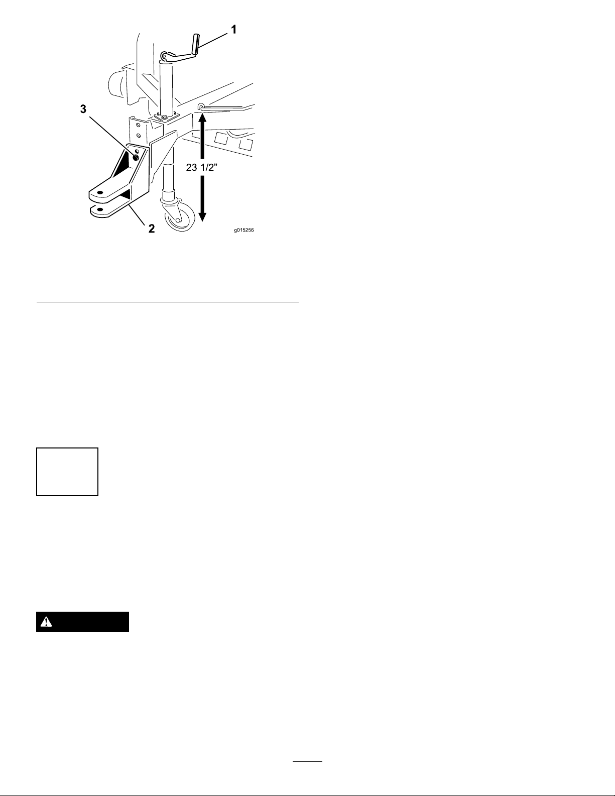
3.Adjustthesweeperjacksothatthedistancefrom
thetopoftheframetothegroundisapproximately
23–1/2inches(59.69cm)(
Figure3).
9
Page 10
3
2
1
g01525 6
23 1/2 ”
Figure3
3.Raisethesweeperjackhandleandlowerthecaster
wheeltoground.
4.Continuetoraisethesweeperwithajackuntilthe
hairpincotterandhitchpincanberemovedfrom
thehitch.
1.Sweeperjack
2.Hitchtongue(Model
07050)
4.Backtheprimemoveruptothesweeper.
5.Adjustthesweeperhitchtonguetothesamelevelas
thehitchoftheprimemoverasfollows:
•Removetheboltsandlocknutssecuringthehitch
tonguetotheframe.
•Raiseorlowerthehitchtonguetotheposition
approximatelylevelwiththeprimemovehitch
andsecureitwiththe2boltsandlocknuts.
3.Adjustingscrews
3
RemovingSweeperfromthe
PrimeMover
NoPartsRequired
Procedure
WARNING
Alwaysemptythesweeperhopperbefore
disconnectingthehopperfromtheprimemoveror
thesweepermaytipbackwardsandcauseinjury.
1.Parkthesweeperonalevelsurfaceandblockthe
wheels.
2.Insertthecastorwheelontothejacktube.
10
Page 11

ProductOverview
2
1
g015265
3
2
1
g015266
2
1
g015267
Controls
FlapLever
Movetheapleverdownwardtotheengagedposition
andupwardforthedisengagedposition.Movethelever
totheupwardpositionwhentransportingthemachine.
ReelLever
Pushthereelleverforwardtoraisetheextipreel.To
lowertheexreel,pushtheleverforwarduntilthecatch
releases,thenpushtotherearuntiltheleverhitsStop.
Movethelevertotheraisedpositionwhenthemachine
isnotinoperation,whenstoringthemachine,orwhen
transportingthemachine(
Figure4).
Figure5
1.Chokecontrol
2.Ignitionswitch
3.Throttlecontrol
IgnitionSwitch
Theignitionswitch,whichisusedtostartandstopthe
engine,hasthreepositions:Off,Run,andStart.Rotate
thekeyclockwisetotheStartpositiontoengagethe
startermotor.Releasethekeywhentheenginestarts.
ThekeywillmoveautomaticallytotheRunposition.
Toshuttheengineoff,rotatethekeycounterclockwise
totheOffposition.
Figure4
1.Flaplever2.Reellever
ChokeControl
Tostartacoldengine,closethecarburetorchokeby
movingthechokecontrollevertotheOnposition.
Aftertheenginestarts,regulatethechoketokeepthe
enginerunningsmoothly .Openthechokebymoving
thelevertotheOffposition.Startingawarmengine
requireslittleornochoking(
Figure5).
ThrottleControl
Thethrottleisusedtooperatetheengineatvarious
speeds.MovingthethrottlelevertotheFastposition
increasestheenginespeed.Todecreasetheengine
speed,movethelevertotheSlowposition.
TailgateLatchRope
Pullthetailgatelatchropetounlatchthetailgatewhen
emptyingthehopper(Figure6).
Figure6
1.Tailgatelatchrope2.Jackhandle
11
Page 12

Specications
Note:Specicationsanddesignaresubjecttochangewithoutnotice.
Width
Length
Height
EmptyWeight
Operation
Note:Determinetheleftandrightsidesofthe
machinefromthenormaloperatingposition.
AddingFuel
Useunleadedgasoline(87pumpoctaneminimum).
Leaded,regulargasolinemaybeusedifunleadedisnot
available.
Important:Donotusemethanol,gasoline
containingmethanol,orgasoholcontainingmore
than10%ethanolbecausethefuelsystemcouldbe
damaged.Donotmixoilwithgasoline.
DANGER
Incertainconditions,gasolineisextremely
ammableandhighlyexplosive.Areorexplosion
fromgasolinecanburnyouandothersandcan
damageproperty.
•Fillthefueltankoutdoors,inanopenarea,
whentheengineiscold.Wipeupanygasoline
thatspills.
•Donotllthefueltankcompletelyfull.Add
gasolinetothefueltankuntilthelevelis1inch
(25mm)belowthebottomofthellerneck.
Thisemptyspaceinthetankallowsgasoline
toexpand.
•Neversmokewhenhandlinggasoline,andstay
awayfromanopenameorwheregasoline
fumesmaybeignitedbyaspark.
•Storegasolineinanapprovedcontainerand
keepitoutofthereachofchildren.Neverbuy
morethana30-daysupplyofgasoline.
85.5inches(217.17cm)
159inches(403.86cm)
79.5inches(201.93cm)
2160lbs(979.76kg)
DANGER
Incertainconditionsduringfueling,static
electricitycanbereleasedcausingasparkwhich
canignitethegasolinevapors.Areorexplosion
fromgasolinecanburnyouandothersandcan
damageproperty.
•Alwaysplacegasolinecontainersontheground
awayfromyourvehiclebeforelling.
•Donotllgasolinecontainersinsideavehicle
oronatruckortrailerbedbecauseinterior
carpetsorplastictruckbedlinersmayinsulate
thecontainerandslowthelossofanystatic
charge.
•Whenpractical,removegas-powered
equipmentfromthetruckortrailerandrefuel
theequipmentwithitswheelsontheground.
•Ifthisisnotpossible,thenrefuelsuch
equipmentonatruckortrailerfromaportable
container,ratherthanfromagasolinedispenser
nozzle.
•Ifagasolinedispensernozzlemustbeused,
keepthenozzleincontactwiththerimofthe
fueltankorcontaineropeningatalltimesuntil
fuelingiscomplete.
WARNING
Gasolineisharmfulorfatalifswallowed.
Long–termexposuretovaporscancauseserious
injuryandillness.
•Avoidprolongedbreathingofvapors.
•Keepfaceawayfromnozzleandgastankor
conditioneropening .
•Keepgasawayfromeyesandskin.
•Donotoperatewithouttheentireexhaust
systeminplaceandinproperworking
condition.
FillingtheFuelTank
Thefueltankcapacityisapproximately4gal(15.14l).
1.Cleanaroundthefueltankcapandremoveit.
2.Fillthetanktoapproximately1inchbelowthetop
ofthetank(thebottomofthellerneck).
12
Page 13

Important:Thisspaceinthetankallows
1
g015257
1
g015258
gasolinetoexpand.Donotllthefueltank
completelyfull.
3.Installthefueltankcapsecurely.
4.Wipeupanygasolinethatmayhavespilled.
CheckingtheEngineOilLevel
ServiceInterval:Beforeeachuseordaily(Checkthe
oilwhentheengineiscold.)
Theengineisshippedwithoilinthecrankcase;
however,theoillevelmustbecheckedbeforeandafter
theengineisrststarted.
Crankcasecapacityisapproximately2qt.(1.9l)with
thelter.
Usehigh-qualityengineoilasdescribedin
ChangingtheEngineOilandFilter(page18).
5.IftheoillevelisbelowtheFullmark,removethe
llertubecapandaddoiluntilthelevelreaches
theFullmarkonthedipstick(
Figure8).Donot
overll.
Figure8
1.Fillercap
Note:Thebesttimetochecktheengineoiliswhen
theengineiscoolbeforeithasbeenstartedforthe
day.Ifithasalreadybeenrun,allowtheoiltodrain
backdowntothesumpforatleast10minutesbefore
checking.Iftheoillevelisatorbelowtheaddmark
onthedipstick,addoiltobringtheoilleveltothefull
mark.Donotoverll.Iftheoillevelisbetweenthefull
andaddmarks,nooiladditionisrequired.
1.Parkthemachineonalevelsurface,stoptheengine,
removethekey,andwaitforallmovingpartsto
stopbeforeleavingtheoperatingposition.
2.Cleanaroundtheoildipsticksothatdirtcannotfall
intothellerholeanddamagetheengine(
Figure7
1.Dipstick
Figure7).
3.Removethedipstick,wipeitclean,andinstallit
untilitisfullyseated.
4.Removethedipstickandchecktheoillevelonthe
dipstick.
TheoillevelshouldbeuptotheFullmarkonthe
metalendofthedipstick.
Important:Donotoverllthecrankcasewith
oilbecausethismaycauseenginedamage.Do
notruntheenginewithoilbelowthelowmark
becausetheenginemaybedamagedasaresult.
6.Installthellertubecapanddipstick.
StartingandStoppingthe
Engine
StartingtheEngine
1.PlaceallofthecontrolsintheOfforDisengaged
position.
2.MovethethrottlelevermidwaybetweentheSlow
andFastposition.
3.MovethechokelevertotheOnposition.
Note:Chokeisnotrequiredwhenstartingawarm
engine.
4.Insertthekeyintotheignitionswitchandrotateit
clockwisetostarttheengine.Releasethekeywhen
theenginestarts.Regulatethechoketokeepthe
enginerunningsmoothly.
Important:Topreventoverheatingofthe
startermotor,donotengagethestarterlonger
than10seconds.After10secondsofcontinuous
cranking,wait60secondsbeforeengagingthe
startermotoragain.
5.Movethethrottlelevertothedesiredenginespeed.
6.Pulltheapleverasfarforwardaspossible.
7.Pushthereelleverforwarduntilthecatchreleases,
thenpushittotherearuntiltheleverhitsStop.
13
Page 14

Note:Donotallowthesweepertostandstillwith
1
g015259
1
g015261
1
g015262
therakeengagedasturfdamagemayoccur.
StoppingtheEngine
1.MovethethrottlelevertotheSlowposition.
2.Lettheengineidlefor60seconds.
3.TurntheignitionkeytotheOffpositionand
removethekey.
Note:Tostopthemachineinanemergency,move
theignitionswitchtotheOffposition.
Figure10
1.Locknut
TransportingtheMachine
1.Lifteachendofthereelandremovethetransport
hooksbeforeoperatingthemachine(Figure9).
Figure9
1.Transporthook
2.Supporttheextipreel,broom,orthatchingreel
withthetransporthooks.
3.Turnthedepthadjustmentboltuntiltherake
slightlycontactsthetopoftheturfgrass.Ifa
broomisinstalled,slightcontactshouldbemade
withthesurface.Whenthebroomisoperating,the
contactwidthsurfaceshouldbeabout1inch(25.4
mm)wideacrosstheentirelengthofthebroom
Figure11).
(
Figure11
1.Depthadjustingbolt
4.Repeattheprocedureontheoppositesideofthe
machine.
AdjustingtheRakeDepth
Theextipreelshouldbeadjustedtoensurethatthe
raketipsslightlytouchsurfacebutdonotpenetratethe
turf.Iftheraketipspenetratetheturf,improperdebris
pickupcouldresult.
1.Positionthemachineonalevelsurface.
2.Loosenthelocknutonthedepthadjustmentboltso
thatitcanbeturned(Figure10).
5.Tightentheadjustmentlocknut.
AdjusttheRubberFlap
Forthebestdebrispickupresults,themetalportionof
thefrontapshouldbeverticaltotheground.
1.Movetheatleverforwardtolowertheat
(Figure12).
14
Page 15

2
1
g015263
Figure12
2
1
g015264
1.Rubberap
2.Metaledge
2.Loosenthejamnutontopofthestopandrotate
theadjustmentboltupordownuntiltheapis
verticaltotheground(Figure13).
tothesweeperframewiththetransporthooks.
Shouldthegaugewheelarmfalltotheground,
damagetothesweepermayoccur.
OperatingTips
General
•Beforestartingtosweep,surveyareatodetermine
thebestdirectiontosweep.
Note:Tomaintainastraightlinewhensweeping,
sightofanobjectintheforeground.
•Alwaystrytomakealong,continuousrunwitha
slightoverlaponthereturnrun.
•Onturfareas,theextipreelwillpickuptwigs,
clippings,leaves,pineneedlesandcones,small
debris(beveragecans,smallbottles,paperplates,
etc.).
•Theraketeetharemadeofexiblenylonandeasily
changed.Topreventdamage,therakeisprotected
fromsolidobstructionsbyspringaction.Thenylon
teethwillnotmarbronze,stonemarkers,sidewalks
orpavement.
Figure13
1.Adjustmentbolt
2.Stop
3.Tightenthejamnuttosecuretheadjustment.
Note:Theapmaybepositionedinraisedposition
whenpickinguplargeamountsofleaves.
InspectandCleanupafter
Operation
Whenthesweepinghasbeencompleted,thoroughly
cleanandwashthemachine.Airoutthedryhopper.
Aftercleaning,itisrecommendedthatthemachine
beinspectedforpossibledamagetothemechanical
componentsandblower.Theseprocedureswillensure
thatthemachinewillperformsatisfactorilyduringthe
nextsweepingoperation.
•Becauseofitsuniquedesign,thesweeperalso
groomstheturf.Theextipreelcombsthrough
andliftsgrassforauniformcutwhenmowed.As
itcleans,thelightscarifyingactionincreasewater
andpesticidepenetration,thusreducingtheneed
forrenovation.
Important:Donotmakesharpturnswhen
usingthethatchingreelasdamagetoturfmay
occur.
Important:Donotoperatesweeperwhilereel
isturningandintheraisedposition.Damage
totherakeandtiresmayresultifteethcomein
contactwithtires.
•Toemptyhopper,pulltailgatelatchrope.
CAUTION
Thisproductmayexceednoiselevelsof85
dB(A)attheoperatorposition.Earprotectors
arerecommended,forprolongedexposure,
toreducethepotentialofpermanenthearing
damage.
Important:Whentowingthesweeperforlong
distances,fastenthegaugewheelarmsecurely
15
Page 16

Maintenance
Note:Determinetheleftandrightsidesofthemachinefromthenormaloperatingposition.
Important:Refertoyourengine
Man ual
foradditionalmaintenanceprocedures.
RecommendedMaintenanceSchedule(s)
MaintenanceService
Interval
Aftertherst50hours
Beforeeachuseordaily
Every25hours
Every50hours
Every100hours
Every200hours
Every600hours
MaintenanceProcedure
•Changetheengineoilandlter.
•Checktheengineoillevel.(Checktheoilwhentheengineiscold.)
•Checkthetirepressure.
•Lubricatethebearings.
•ServicetheAirCleaner.
•Checktheelectrolytelevelandcleanthebattery .
•Checkthebatterycableconnections.
•OiltheSweeperJack.
•Changetheengineoilandlter.
•Removedebrisfromengine.
•Checkthesparkplugs.
•Replacethefuellter.
Operator's
Beforestorage
•RefertotheStoragesectionforproceduresnecessarytoperformbeforestoringthe
machineformorethan30days.
16
Page 17

Lubrication
g015268
g015269
g015270
g015271
Lubrication
ServiceInterval:Every25hours
TheRake–O–Vachasgreasettingsthatmustbe
lubricatedregularlywithNo.2GeneralPurposeLithium
BaseGrease.Lubricatethebearingsafterevery30
hoursofoperationorwhenevermachineiswashed
withwater.Bearingsandbushingsmustbelubricated
dailywhenoperatingconditionsareextremelydusty
anddirty.Dustyanddirtyoperatingconditionscould
causedirttogetintothebearingsandbushings,resulting
inacceleratedwear.Thegreasettingsthatmustbe
lubricatedare:thegaugewheelbearings,thereelshaft
bearings,theimpellershaftbearings,thejackshaft
bearings,andtheleftandrighttrailingarms.
1.Wipethegreasettingscleantoensurethatforeign
mattercannotbeforcedintothebearingorbushing.
Figure15
2.Pumpgreaseintothebearingorbushing(
Figure15,andFigure16).
Figure14
Figure14,
Figure16
3.Wipeupanyexcessgrease.
OiltheSweeperJack
ServiceInterval:Every50hours—OiltheSweeper
Jack.
OiltheSweeperjackafterevery50hoursofoperation
(Figure17).
Figure17
17
Page 18

EngineMaintenance
3
4
2
1
g015273
2
1
g015272
ServicingtheAirCleaner
ServiceInterval:Every25hours
1.Releasethelatchessecuringtheaircleanercoverto
theaircleanerbody.Separatethecoveroftheair
cleanerfromthebodyoftheunit.Cleantheinside
oftheaircleanercover(Figure18).
7.Insertthenewlterproperlyintotheaircleaner
body.Makesurethelterissealedproperlyby
applyingpressuretotheouterrimofthelterwhen
installing.Donotpressontheexiblecenterofthe
lter.
8.Reinstallthecoverandsecurethelatches.Makesure
thecoverispositionedwiththetopsideup.
ChangingtheEngineOiland
Filter
ServiceInterval:Aftertherst50hours
Every100hours—Changetheengine
oilandlter.
Note:Changetheoilandltermorefrequentlywhen
operatingconditionsareextremelydustyorsandy.
OilType:Detergentoil(APIserviceSJ,SK,SL,or
higher)
CrankcaseCapacity:w/lter,2.0qt.(1.9l)
Figure18
1.Aircleanerlatches
2.Dustcup
3.Primarylter
4.Safetylter
2.Gentlyslidetheprimarylteroutoftheaircleaner
bodytoreducetheamountofdustdislodged.Avoid
knockingthelteragainsttheaircleanerbody.Do
notremovethesafetylter.
3.Inspecttheprimarylterandreplaceitifthereis
damage.Donotwashorreuseadamagedlter.
Important:Donotattempttocleanthesafety
lter.Replacethesafetylterwithanewone
afterevery3primarylterservices.
4.Blowcompressedairfromtheinsidetotheoutside
ofthedrylterelement.Donotexceed100psito
preventdamagetotheelement.
1.Starttheengineandletitrunforveminutes.This
warmstheoilsoitdrainsbetter.
2.Parkthemachinesothatthedrainsideisslightly
lowerthantheoppositesidetoensurethattheoil
drainscompletely .
3.Settheparkingbrake,stoptheengine,andremove
thekey .
4.Placeapanbelowtheoildrain.Removetheoildrain
plugtoallowtheoiltodrain(
Figure19).
5.Keeptheairhosenozzleatleast2inchesfrom
thelterandmovethenozzleupanddownwhile
rotatingthelterelement.Inspectthelterfor
holesandtearsbylookingthroughtheltertowarda
brightlight.
6.Inspectthenewlterforanyshippingdamages.
Checkthesealingendofthelter.Donotinstalla
damagedlter.
Figure19
1.Drainplug
18
2.Oillter
Page 19

5.Whentheoilhasdrainedcompletely,replacethe
plug.
engineisoperatingproperly.Ablackcoatingonthe
insulatorusuallymeanstheaircleanerisdirty.
Note:Disposeoftheusedoilatacertiedrecycling
center.
6.Placeashallowpanorragundertheltertocatchoil.
7.Removetheoldlterandwipethesurfaceofthe
lteradaptergasket.
8.Pourthenewoilofthepropertypethroughthe
centerholeofthelter.Stoppouringwhentheoil
reachesthebottomofthethreads.
9.Allowaminuteortwofortheoiltobeabsorbedby
ltermaterial,thenpourofftheexcessoil.
10.Applyathincoatofnewoiltotherubbergasket
onthereplacementlter.
11.Installthereplacementoilltertothelteradapter.
Turntheoillterclockwiseuntiltherubbergasket
contactsthelteradapter,thentightenthelteran
additional1/2turn.Donotovertighten.
12.Checktheoillevel;referto
CheckingtheEngineOilLevel(page13).
13.Slowlyaddadditionaloiltobringtheleveltothefull
markonthedipstick.
Important:Nevercleanthesparkplugs.Always
replacethesparkplugswhentheyhaveablack
coating,wornelectrodes,anoilylm,orcracks.
Figure20
1.Centerelectrodeinsulator3.Airgap(nottoscale)
2.Sideelectrode
2.Checkthegapbetweenthecenterandsideelectrodes
(Figure20).
3.Bendthesideelectrode(
correct.
Figure20)ifthegapisnot
14.Replacethellcap.
ServicingtheSparkPlugs
ServiceInterval:Every200hours—Checkthespark
plugs.
Ensurethattheairgapbetweenthecenterandside
electrodesiscorrectbeforeinstallingeachsparkplug.
Useasparkplugwrenchforremovingandinstallingthe
sparkplugsandagappingtool/feelergaugetocheckand
adjusttheairgap.Installnewsparkplugsifnecessary.
Type:ChampionRC12YCorequivalent.AirGap:0.03
inch(0.75mm)
RemovingtheSparkPlugs
1.Stoptheengine,settheparkingbrake,andremove
thekey .
2.Pullthewiresoffofthesparkplugs.
3.Cleanaroundthesparkplugs.
4.Removebothsparkplugsandmetalwashers.
CheckingtheSparkPlugs
InstallingtheSparkPlugs
1.Threadthesparkplugsintothesparkplugholes.
2.Tightenthesparkplugsto20ft-lb(27N-m).
3.Pushthewiresontothesparkplugs.
RemoveDebrisfromthe
Engine
ServiceInterval:Every100hours
Toensurepropercooling,keepthegrassscreen,cooling
ns,andotherexternalsurfacesoftheenginecleanat
alltimes.
Every100hoursofoperation(moreoftenunder
extremelydusty,dirtyconditions)removetheblower
housingandothercoolingshrouds.Cleanthecooling
nsandexternalsurfacesasnecessary.Makesurethe
coolingshroudsarereinstalled.
Note:Operatingtheenginewithablockedgrass
screen,dirtyorpluggedcoolingns,orcoolingshrouds
removed,willcauseenginedamageduetooverheating.
1.Lookatthecenterofbothsparkplugs(Figure20).
Ifyouseelightbrownorgrayontheinsulator,the
19
Page 20

FuelSystem
1
g015274
ElectricalSystem
Maintenance
ReplacingtheFuelFilter
ServiceInterval:Every600hours/Yearly(whichever
comesrst)
Important:Neverinstalladirtylterifitis
removedfromthefuelline.
1.Allowthemachinetocooldown.
2.Placeacleancontainerunderthefuellter
Figure21).
(
Maintenance
ServicingtheBattery
ServiceInterval:Every25hours—Checktheelectrolyte
levelandcleanthebattery.
Every25hours—Checkthebattery
cableconnections.
WARNING
CALIFORNIA
Proposition65Warning
Batteryposts,terminals,andrelated
accessoriescontainleadandleadcompounds,
chemicalsknowntotheStateofCalifornia
tocausecancerandreproductiveharm.
Washhandsafterhandling.
DANGER
Figure21
1.Fuellter
3.Removetheclampssecuringthefuelltertothefuel
lines.
4.Installanewltertothefuellineswiththeclamps
previouslyremoved.Filteristobemountedsothat
thearrowpointstowardthecarburetor.
5.Wipeupanyspilledfuel.
Batteryelectrolytecontainssulfuricacidwhichisa
deadlypoisonandcausessevereburns.
•Donotdrinkelectrolyteandavoidcontactwith
skin,eyes,orclothing.Wearsafetyglassesto
shieldyoureyesandrubberglovestoprotect
yourhands.
•Fillthebatterywherecleanwaterisalways
availableforushingtheskin.
Thebatteryelectrolytelevelmustbeproperlymaintained
andthetopofthebatterykeptclean.Ifthemachineis
storedinalocationwheretemperaturesareextremely
high,thebatterywillrundownmorerapidlythanifthe
machineisstoredinalocationwheretemperaturesare
cool.
Checktheelectrolytelevelevery25operatinghoursor,
ifmachineisinstorage,every30days.
Maintainthecelllevelwithdistilledordemineralized
water.Donotllthecellsabovethebottomofthesplit
ringinsideeachcell.
Keepthetopofthebatterycleanbywashingit
periodicallywithabrushdippedinammoniaor
bicarbonateofsodasolution.Flushthetopsurfacewith
wateraftercleaning.Donotremovethellcapswhile
cleaning.
Thebatterycablesmustbetightontheterminalsto
providegoodelectricalcontact.
20
Page 21

WARNING
Incorrectbatterycableroutingcoulddamagethe
machineandcablescausingsparks.Sparkscan
causethebatterygassestoexplode,resultingin
personalinjury.
•Always
cablebeforedisconnectingthepositive(red)
cable.
•Always
beforeconnectingthenegative(black)cable.
Ifcorrosionoccursattheterminals,disconnectthe
cables(negative(–)cablerst)andscrapeclampsand
terminalsseparately.Reconnectthecables(positive(+)
cablerst)andcoattheterminalswithpetroleumjelly.
disconnect
connect
thenegative(black)battery
thepositive(red)batterycable
WARNING
Batteryterminalsormetaltoolscouldshortagainst
metaltractorcomponentscausingsparks.Sparks
cancausethebatterygassestoexplode,resulting
inpersonalinjury.
DriveSystem
Maintenance
TireMaintenance
CheckingtheTirePressure
ServiceInterval:Beforeeachuseordaily
Maintaintheairpressureinthefrontandreartiresat
28psi(193kPa).Checkthepressureatthevalvestem
(Figure22)beforeeachuse.
Figure22
1.Valvestem
•Whenremovingorinstallingthebattery,donot
allowthebatteryterminalstotouchanymetal
partsofthemachine.
•Donotallowmetaltoolstoshortbetween
thebatteryterminalsandmetalpartsofthe
machine.
ChangingtheTires
1.Parkthemachineonaat,levelsurface.Blockthe
othertiretopreventaccidentalrollingorinjury.
2.Placethejackundertheframeoraxleshaftbehind
thewheelandjackupthewheeluntilitjustcontacts
theoor.
WARNING
A2000lb.capacityhydraulicjackshouldbe
usedwhenchangingatire.
3.Loosenalllugboltsandcontinuetojackupuntil
thetirecanberemoved.
4.Reversetheaboveproceduretoinstallatire.Torque
thelugboltsto70–90ft-lb(95–122N-m).
21
Page 22

BeltMaintenance
1
g015278
3
2
1
g015277
InspectingtheBelts
Note:Itisnotnecessarytoremovetheupperbelt
guard(Figure23)tocheckthebelttension.Ifforsome
reasonthebeltguardmustberemoved,removethe4
bolts,washers,andnutssecuringtheguardtotheframe.
Neveroperatethemachinewithouttheguardsinplace.
Figure24
1.Impellerbelt3.Idlerpulley
2.Jackshaftbelt
1.Upperbeltguard
Figure23
InspectingtheImpellerDriveBelt
Checkthetensionbydepressingthebeltatthemid
spanoftheimpellerandclutchpulleyswith4–5lbs
(18–22N)offorce.Thebeltshoulddeect.5inches
(1.27cm).Ifthedeectionisincorrect,proceed
AdjustingtheImpellerDriveBelt(page23).If
to
thedeectioniscorrect,continuenormaloperation
(Figure23).
InspectingtheJackshaftBelt
Checkthetensionbydepressingthebeltatmid
spanofthejackshaftandclutchpulleyswith4–5lbs
(18–22N)offorce.Thebeltshoulddeect.25inches
(6.35mm).Ifthedeectionisincorrect,proceedto
AdjustingtheJackshaftBelt(page23).Ifthedeection
iscorrect,continuenormaloperation(Figure23).
InspectingtheReelDriveBelt
Checkthetensionbydepressingthebeltatmidspanof
theidlerpulleyandthereeldriverpulleywith25–29lbs
(111–129N)offorce.Thebeltshoulddeect.25inches
(6.35mm).Ifthedeectionisincorrect,proceedto
AdjustingtheReelDriveBelt(page23).Ifthedeection
iscorrect,continuenormaloperation.
22
Page 23

AdjustingtheBelts
1
g015279
1
g015280
g015281
1
2
1
g015282
AdjustingtheImpellerDriveBelt
1.Loosentheenginemountingbolts(Figure25).
Figure25
2.Ifthebelthastoomuchslack,loosentheidlerpulley
nut,pressforwardontheidlerpulleyuntilthedesired
tensionisobtainedandretightentheidlerpulleynut.
3.Ifthebeltistootight,loosentheidlerpulleynut,
pullrearwardontheidlerpulleyuntilthedesired
tensionisobtainedandtightentheidlerpulleynut.
AdjustingtheReelDriveBelt
1.Removethe2bolts,nut,retainingnut,andwasher
securingthelowerbeltguardtotheframe.Remove
theguard(
Figure27).
1.Enginemountingbolts
2.Turnthebeltadjustingboltuntilthedesiredbelt
tensionisobtained.Slightlytightentheengine
mountingbolts.Adjusttheenginesothatitis
parallelwithframe.Continuetighteningtheengine
mountingbolts(
Figure26).
Figure26
Figure27
1.Lowerbeltguard
2.Ifthebelthastoomuchslack,loosentheidlerpulley
nut,pressdownontheidlerpulleyuntilthedesired
tensionisobtainedandtightentheidlerpulleynut
(Figure28).
1.Adjustingbolt
3.Whenevertheimpellerbeltisadjusteditisnecessary
toreadjustthejackshaftbelt(enginedrive)orchain
(PTOdrive).
AdjustingtheJackshaftBelt
1.Removethe4bolts,washersandnutssecuringthe
uppershroudtotheframe(
Figure23).
Figure28
1.Reeldrivebelt2.Idlerpulley
3.Ifthebeltistootight,loosentheidlerpulleynut,pull
upwardontheidlerpulleyuntilthedesiredtensionis
obtainedandtightentheidlerpulleynut.
4.Installthebeltguard.Ensurethatthereisclearance
betweenthebeltandthebeltguard.
23
Page 24

ChangingtheRubber
2
1
g015275
1
3
2 g015283
PulleyRemoval
Flap
Replacetherubberapwhenitbecomeswornor
damaged.
CAUTION
Changerubberaponaat,levelsurfaceandblock
wheelstopreventsweeperfromrolling.Failureto
dosomayresultinpersonalinjury.
1.Removethe10bolts,washers,andnutsonthe
mountingapandapretainer(Figure29).
1.Removetheboltsandlockwashersoneatatimeand
screwthemintotheadjoiningholes(Figure30).
Figure30
1.Bolts&locknuts
2.Taperlockbushing
3.Taperlockreleasehole
Figure29
1.Rubberap
2.Replacewiththenewrubberapandfastenit
securely.
2.Flapretainer
2.Turneachboltthesamenumberoftimesuntilthe
lockseparates.Thepulleywillnowslideoffofthe
shaft.
24
Page 25

FlexTipReelRemoval
1
2
g015286
FlexTipRakeRod
1.Placethemachineonahardandlevelsurface.
2.Raisethefrontofthesweeperashighaspossible
byloweringthejack.
3.Raisethereeltothehighestposition.
4.Removethelowerbeltguardandreeldrivebelt
Figure27andFigure28).
(
5.Removethe2bolts,lockwashers,andnutssecuring
thereelshaftbearingstothereelsupportarmson
eachsideofthesweeper.Lowertheextipreelto
theground.
6.Liftthereelsupportarmstothehighestposition.
7.Slidetheendoftherakerearwardandpullitout
fromunderthemachine.
OrFingerPlate
Replacement
1.Removetheboltandlocknutfromoneendofthe
reel(Figure31).
Figure31
1.boltandlocknut2.Locknut
2.Removethelocknutonlyfromtheoppositeendof
thereel.
3.Drivetherodfromtheendplate.Drivetherodfrom
theendwithoutthetabweldedtoit.
4.Removethengerplatesorrodsasrequiredand
replace.
5.Lineupthengerplatewiththerodanddrivethe
rodbackthroughtheendplate.
6.Attachthebolt,locknuts,andhookupthesprings.
25
Page 26

FlexTipRakeTine
3
2
1
g015287
1
g015288
g015289
BrushHalfReplacement
Replacement
1.Removethetineretainerandslidethedamagedtine
out(Figure32).
1.Removethebrushfromthesweeper.
2.Loosentheclampswithanallenwrenchandremove
itfromthebrushhalves(
1.Clamp
Figure33).
Figure33
Figure32
1.Fingerplate3.Tine
2.Tineretainer
3.Separatethebrushhalvesanddiscardthedamaged
section(s)(Figure34).
2.Bendthenewtineinhalfandslideitintoposition.
3.Placethetinebracketoverthecurvedendofthetine
andfastenitsecurelywiththeboltandlockwasher.
Figure34
4.Installthenewbrushsectionbypushingthem
togetherandsecuringbothendswiththebrush
clamps.Whentheendshavebeensecured,fasten
thebrushwiththeremainingclamps.
26
Page 27

Cleaning
g015276
CleaningtheBlowerHousing
WARNING
Beforeremovinganydebrisfromblowerhousing,
disengageP .T.O.drive,stopengine(s)andmake
certainallmovingpartshavestoppedorpersonal
injurymayoccur.
1.Makesuretheimpellerhasstoppedrotatingbefore
removingtheaccessplates.
2.Loosenthe2wingnutssecuringtheaccessplate
Figure35).
(
Storage
1.Settheparkingbrakeandturntheignitionkeytooff.
Removethesparkplugwireandthekey.
2.Removegrass,dirt,andgrimefromtheexternal
partsoftheentiremachine,especiallytheengine.
Cleandirtandchafffromtheoutsideoftheengine’ s
cylinderheadnsandblowerhousing.
3.Servicetheaircleaner;referto
ServicingtheAirCleaner(page18).
4.Changethecrankcaseoil;referto
ChangingtheEngineOilandFilter(page18).
5.Checkthetirepressure;referto
CheckingtheTirePressure(page21).
6.Checktheconditionofthetines.
7.Ifyouwillbestoringthemachineformorethan30
days,prepareitasfollows:
A.Removethebatteryterminalsfromthebattery
postsandremovethebatteryfromthemachine.
B.Cleanthebattery,terminals,andpostswithawire
brushandbakingsodasolution.
C.Coatthecableterminalsandbatterypostswith
Grafo112Xskin-overgrease(ToroPartNo.
505-47)orpetroleumjellytopreventcorrosion.
D.Slowlyrechargethebatteryevery60daysfor24
hourstopreventleadsulfationofthebattery.To
preventthebatteryfromfreezing,makesureit
isfullycharged.Thespecicgravityofafully
chargedbatteryis1.265to1.299.
Figure35
AccessPlate
3.Swingtheaccessplatetoonesideallowingthe
removalofdebris.
4.Afterthedebrishasbeenremoved,lowertheaccess
plateandsecurewiththewingnuts.Repeatthe
procedureontheotheraccessplate.
WARNING
Chargingthebatteryproducesgassesthat
canexplode.
Neversmokenearthebatteryandkeep
sparksandamesawayfromit.
E.Eitherstorethebatteryontheshelforonthe
machine.Leavethecablesdisconnectedifit
isstoredonthemachine.Storeitinacool
atmospheretoavoidquickdeteriorationofthe
chargeinthebattery.
F.Addapetroleumbasedstabilizer/conditionerto
fuelinthetank.Followmixinginstructionsfrom
stabilizermanufacture.Donotuseanalcohol
basedstabilizer(ethanolormethanol).
Note:Afuelstabilizer/conditionerismost
effectivewhenmixedwithfreshgasolineand
usedatalltimes.
G.Runtheenginetodistributeconditionedfuel
throughthefuelsystem(5minutes).
27
Page 28

H.Stoptheengine,allowittocoolanddrainthe
fueltank.
I.Restarttheengineandrunituntilitstops.
J.Choketheengine.Startandruntheengineuntil
itwillnotstart.
K.Disposeofthefuelproperly.Recycleasperlocal
codes.
Important:Donotstore
stabilizer/conditionedgasolineover90
days.
8.Removethesparkplugsandcheckthecondition;
referto
ServicingtheSparkPlugs(page19).With
thesparkplugsremovedfromtheengine,pour
twotablespoonsofengineoilintoeachsparkplug
hole.Nowusethestartertocranktheengineand
distributetheoilinsidethecylinders.Installthespark
plugs.Donotinstallthewiresonthesparkplugs.
9.Checkandtightenallbolts,nuts,andscrews.Repair
orreplaceanypartthatisdamagedordefective.
10.Washanddrytheentireunit.Removethetines,clean
andoilthem.Spraylightoilmistonthecoringhead
bearings(crank&damperlinks).
Important:Youcanwashthemachinewith
milddetergentandwater.Donotpressurewash
themachine.Avoidexcessiveuseofwater,
especiallyneartheengine.
Note:Runthemachinewiththeengineathighidle
for2to5minutesafterwashing.
11.Paintallscratchedorbaremetalsurfaces.Paintis
availablefromyourAuthorizedServiceDistributor.
12.Secureservicelatchiftheaeratoristobestoredfor
morethanacoupledays.
13.Storethemachineinaclean,drygarageorstorage
area.Removethekeyfromtheignitionswitchand
keepitoutofreachofchildrenorotherunauthorized
users.
14.Coverthemachinetoprotectitandkeepitclean.
28
Page 29

Notes:
29
Page 30

Notes:
30
Page 31

Notes:
31
Page 32

TheT oroTotalCoverageGuarantee
ALimitedWarranty
ConditionsandProductsCovered
TheT oroCompanyanditsafliate,T oroWarrantyCompany ,pursuant
toanagreementbetweenthem,jointlywarrantyourT oroCommercial
product(“Product”)tobefreefromdefectsinmaterialsorworkmanship
fortwoyearsor1500operationalhours*,whicheveroccursrst.This
warrantyisapplicabletoallproductswiththeexceptionofAerators
(refertoseparatewarrantystatementsfortheseproducts).Wherea
warrantableconditionexists,wewillrepairtheProductatnocosttoyou
includingdiagnostics,labor,parts,andtransportation.Thiswarranty
beginsonthedatetheProductisdeliveredtotheoriginalretailpurchaser.
*Productequippedwithanhourmeter.
InstructionsforObtainingWarrantyService
YouareresponsiblefornotifyingtheCommercialProductsDistributoror
AuthorizedCommercialProductsDealerfromwhomyoupurchasedthe
Productassoonasyoubelieveawarrantableconditionexists.Ifyouneed
helplocatingaCommercialProductsDistributororAuthorizedDealer,or
ifyouhavequestionsregardingyourwarrantyrightsorresponsibilities,
youmaycontactusat:
ToroCommercialProductsServiceDepartment
ToroWarrantyCompany
811 1LyndaleAvenueSouth
Bloomington,MN55420-1196
952–888–8801or800–952–2740
E-mail:commercial.warranty@toro.com
OwnerResponsibilities
AstheProductowner,youareresponsibleforrequiredmaintenance
andadjustmentsstatedinyourOperator'sManual.Failuretoperform
requiredmaintenanceandadjustmentscanbegroundsfordisallowinga
warrantyclaim.
ItemsandConditionsNotCovered
Notallproductfailuresormalfunctionsthatoccurduringthewarranty
periodaredefectsinmaterialsorworkmanship.Thiswarrantydoesnot
coverthefollowing:
•Productfailureswhichresultfromtheuseofnon-T ororeplacement
parts,orfrominstallationanduseofadd-on,ormodiednon-T oro
brandedaccessoriesandproducts.Aseparatewarrantymaybe
providedbythemanufactureroftheseitems.
•Productfailureswhichresultfromfailuretoperformrecommended
maintenanceand/oradjustments.Failuretoproperlymaintainyour
ToroproductpertheRecommendedMaintenancelistedinthe
Operator’sManualcanresultinclaimsforwarrantybeingdenied.
•ProductfailureswhichresultfromoperatingtheProductinan
abusive,negligent,orrecklessmanner.
•Partssubjecttoconsumptionthroughuseunlessfoundtobe
defective.Examplesofpartswhichareconsumed,orusedup,
duringnormalProductoperationinclude,butarenotlimitedto,brake
padsandlinings,clutchlinings,blades,reels,rollersandbearings
(sealedorgreasable),bedknives,sparkplugs,castorwheelsand
bearings,tires,lters,belts,andcertainsprayercomponentssuchas
diaphragms,nozzles,andcheckvalves,etc.
•Failurescausedbyoutsideinuence.Conditionsconsideredtobe
outsideinuenceinclude,butarenotlimitedto,weather,storage
practices,contamination,useofunapprovedfuels,coolants,
lubricants,additives,fertilizers,water,orchemicals,etc.
•Failureorperformanceissuesduetotheuseoffuels(e.g.gasoline,
diesel,orbiodiesel)thatdonotconformtotheirrespectiveindustry
standards.
•Normalnoise,vibration,wearandtear,anddeterioration.
•Normal“wearandtear”includes,butisnotlimitedto,damageto
seatsduetowearorabrasion,wornpaintedsurfaces,scratched
decalsorwindows,etc.
Parts
Partsscheduledforreplacementasrequiredmaintenancearewarranted
fortheperiodoftimeuptothescheduledreplacementtimeforthatpart.
Partsreplacedunderthiswarrantyarecoveredforthedurationofthe
originalproductwarrantyandbecomethepropertyofT oro.T orowill
makethenaldecisionwhethertorepairanyexistingpartorassemblyor
replaceit.T oromayuseremanufacturedpartsforwarrantyrepairs.
DeepCycleandLithium-IonBatteryWarranty:
DeepcycleandLithium-Ionbatterieshaveaspeciedtotalnumberof
kilowatt-hourstheycandeliverduringtheirlifetime.Operating,recharging,
andmaintenancetechniquescanextendorreducetotalbatterylife.Asthe
batteriesinthisproductareconsumed,theamountofusefulworkbetween
chargingintervalswillslowlydecreaseuntilthebatteryiscompletelyworn
out.Replacementofwornoutbatteries,duetonormalconsumption,
istheresponsibilityoftheproductowner .Batteryreplacementmaybe
requiredduringthenormalproductwarrantyperiodatowner’sexpense.
Note:(Lithium-Ionbatteryonly):ALithium-Ionbatteryhasapartonly
proratedwarrantybeginningyear3throughyear5basedonthetime
inserviceandkilowatthoursused.RefertotheOperator'sManualfor
additionalinformation.
MaintenanceisatOwner’sExpense
Enginetune-up,lubrication,cleaningandpolishing,replacementoflters,
coolant,andcompletingrecommendedmaintenancearesomeofthe
normalservicesToroproductsrequirethatareattheowner’sexpense.
GeneralConditions
RepairbyanAuthorizedT oroDistributororDealerisyoursoleremedy
underthiswarranty.
NeitherTheToroCompanynorToroWarrantyCompanyisliablefor
indirect,incidentalorconsequentialdamagesinconnectionwiththe
useoftheT oroProductscoveredbythiswarranty,includingany
costorexpenseofprovidingsubstituteequipmentorserviceduring
reasonableperiodsofmalfunctionornon-usependingcompletion
ofrepairsunderthiswarranty.ExceptfortheEmissionswarranty
referencedbelow,ifapplicable,thereisnootherexpresswarranty .
Allimpliedwarrantiesofmerchantabilityandtnessforuseare
limitedtothedurationofthisexpresswarranty .
Somestatesdonotallowexclusionsofincidentalorconsequential
damages,orlimitationsonhowlonganimpliedwarrantylasts,sothe
aboveexclusionsandlimitationsmaynotapplytoyou.Thiswarranty
givesyouspeciclegalrights,andyoumayalsohaveotherrightswhich
varyfromstatetostate.
Noteregardingenginewarranty:
TheEmissionsControlSystemonyourProductmaybecoveredby
aseparatewarrantymeetingrequirementsestablishedbytheU.S.
EnvironmentalProtectionAgency(EP A)and/ortheCaliforniaAir
ResourcesBoard(CARB).Thehourlimitationssetforthabovedonot
applytotheEmissionsControlSystemWarranty .RefertotheEngine
EmissionControlWarrantyStatementsuppliedwithyourproductor
containedintheenginemanufacturer’sdocumentationfordetails
CountriesOtherthantheUnitedStatesorCanada
CustomerswhohavepurchasedT oroproductsexportedfromtheUnitedStatesorCanadashouldcontacttheirToroDistributor(Dealer)toobtain
guaranteepoliciesforyourcountry ,province,orstate.IfforanyreasonyouaredissatisedwithyourDistributor'sserviceorhavedifcultyobtaining
guaranteeinformation,contacttheT oroimporter.
374-0253RevB
 Loading...