

Page 1
8-Blade,11-Blade,and14-Blade
DPAReelMower
FormNo.3397-897RevA
Greensmaster
®
3120,3150,or3250-DSeries
TractionUnit
ModelNo.04652—SerialNo.316000001andUp
ModelNo.04654—SerialNo.316000001andUp
ModelNo.04656—SerialNo.316000001andUp
Registeratwww.T oro.com.
OriginalInstructions(EN)
*3397-897*A
Page 2
ThisproductcomplieswithallrelevantEuropeandirectives.
G020063
Fordetails,pleaseseetheDeclarationofIncorporation(DOI)
atthebackofthispublication.
WARNING
CALIFORNIA
Proposition65W arning
Thisproductcontainsachemicalorchemicals
knowntotheStateofCaliforniatocausecancer,
birthdefects,orreproductiveharm.
Useofthisproductmaycauseexposureto
chemicalsknowntotheStateofCalifornia
tocausecancer,birthdefects,orother
reproductiveharm.
Introduction
Thiscuttingunitisdesignedforcuttingturfongreensand
smallfairwaysofgolfcourses.
Readthisinformationcarefullytolearnhowtooperateand
maintainyourproductproperlyandtoavoidinjuryand
productdamage.Youareresponsibleforoperatingthe
productproperlyandsafely.
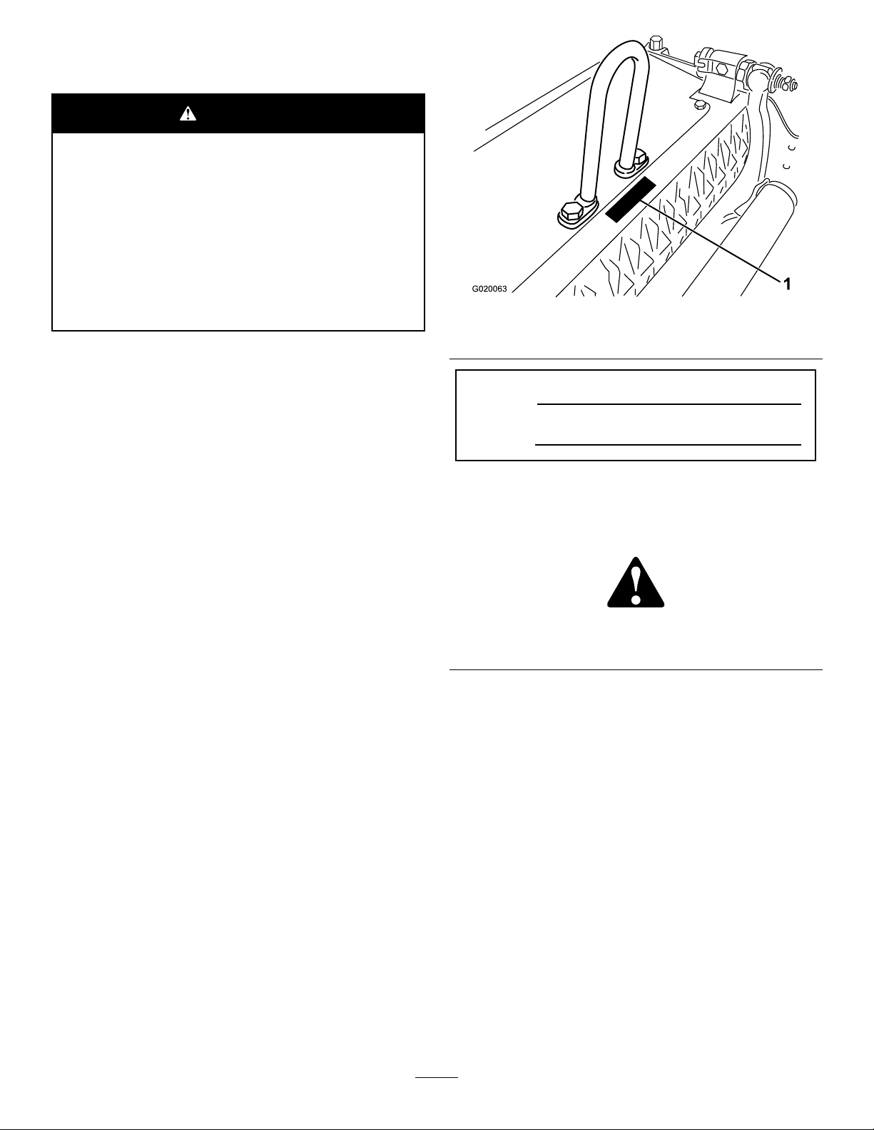
Figure1
1.Locationofthemodelandserialnumbers
ModelNo.
SerialNo.
Thismanualidentiespotentialhazardsandhassafety
messagesidentiedbythesafety-alertsymbol(Figure2),
whichsignalsahazardthatmaycauseseriousinjuryordeath
ifyoudonotfollowtherecommendedprecautions.
YoumaycontactTorodirectlyatwww .Toro.comforproduct
andaccessoryinformation,helpndingadealer,ortoregister
yourproduct.
Wheneveryouneedservice,genuineT oroparts,oradditional
information,contactanAuthorizedServiceDealerorToro
CustomerServiceandhavethemodelandserialnumbersof
yourproductready.Figure1identiesthelocationofthe
modelandserialnumbersontheproduct.Writethenumbers
inthespaceprovided.
Figure2
1.Safety-alertsymbol
Thismanualuses2wordstohighlightinformation.
Importantcallsattentiontospecialmechanicalinformation
andNoteemphasizesgeneralinformationworthyofspecial
attention.
©2015—TheToro®Company
8111LyndaleAvenueSouth
Bloomington,MN55420
Contactusatwww.Toro.com.
2
PrintedintheUSA
AllRightsReserved
Page 3

Contents
Safety
Safety...........................................................................3
Hauling..................................................................4
SafetyandInstructionalDecals.................................4
Setup............................................................................5
InstallingtheRoller..................................................5
InstallingtheBallStuds............................................5
InstallingtheHoopLink,OffsetLink,orChain
Link...................................................................5
RepositioningtheCounterWeights............................6
AdjustingtheCuttingUnit........................................7
ProductOverview..........................................................8
Specications.........................................................8
Attachments/Accessories.........................................8
Operation.....................................................................8
Maintenance..................................................................9
SupportingtheCuttingUnit......................................9
AdjustingtheBedknife-to-ReelContact......................9
AdjustingtheRear-RollerHeight..............................10
AdjustingtheHeightofCut.....................................11
AdjustingtheCut-OffBar.......................................12
ServicingtheBedbar...............................................12
BedknifeSpecications...........................................14
BacklappingtheCuttingUnit...................................14
ThismachinehasbeendesignedinaccordancewithENISO
5395:2013andANSIB71.1-2012.
Hazardcontrolandaccidentpreventionaredependent
upontheawareness,concern,andpropertraining
ofthepersonnelinvolvedintheoperation,transport,
maintenance,andstorageofthemachine.Improper
useormaintenanceofthemachinecanresultininjury
ordeath.T oreducethepotentialforinjuryordeath,
complywiththefollowingsafetyinstructions.
•Read,understand,andfollowallinstructionsinthe
traction-unitandcutting-unitoperator’smanualsbefore
operatingthemachine.
•Neverallowchildrentooperatethemachine.Donot
allowadultstooperatethemachinewithoutproper
instruction.Onlytrainedoperatorswhohavereadthis
manualshouldoperatethemachine.
•Neveroperatethemachinewhenundertheinuenceof
drugsoralcohol.
•Keepallshieldsandsafetydevicesinplace.Ifashield,
safetydeviceordecalisillegibleordamaged,repairor
replaceitbeforecommencingoperation.Alsotighten
anyloosenuts,bolts,andscrewstoensurecuttingunitis
insafeoperatingcondition.
•Wearappropriateclothingincludingsubstantial,
slip-resistantfootwear,safetyglasses,andhearing
protection.Tiebacklonghair.Donotwearjewelry.
•Removealldebrisorotherobjectsthatthecutting-unit
bladesmightpickupandthrow.Keepallbystandersaway
fromtheworkingarea.
•Ifthecuttingbladesstrikeasolidobjectortheunit
vibratesabnormally,stopandshuttheengineoff.Check
thecuttingunitfordamagedparts.Repairanydamage
beforestartingthecuttingunit.
•Lowerthecuttingunitstothegroundandremovethekey
fromtheignitionswitchwheneveryouleavethemachine.
•Ensurethatthemachineisinsafeoperatingconditionby
keepingnuts,bolts,andscrewstight.
•Removethekeyfromignitionswitchtopreventaccidental
startingoftheenginewhenservicing,adjusting,orstoring
themachine.
•Performonlythosemaintenanceinstructionsdescribed
inthismanual.Ifthemachineneedsmajorrepairsoryou
needassistance,contactanAuthorizedToroDistributor.
•Toensureoptimumperformanceandcontinuedsafety
certicationofthemachine,useonlygenuineToro
replacementpartsandaccessories.Replacementparts
andaccessoriesmadebyothermanufacturerscouldbe
dangerous,andsuchusecouldvoidtheproductwarranty.
3
Page 4
Hauling
•Usecarewhenloadingorunloadingthemachineintoa
traileroratruck.
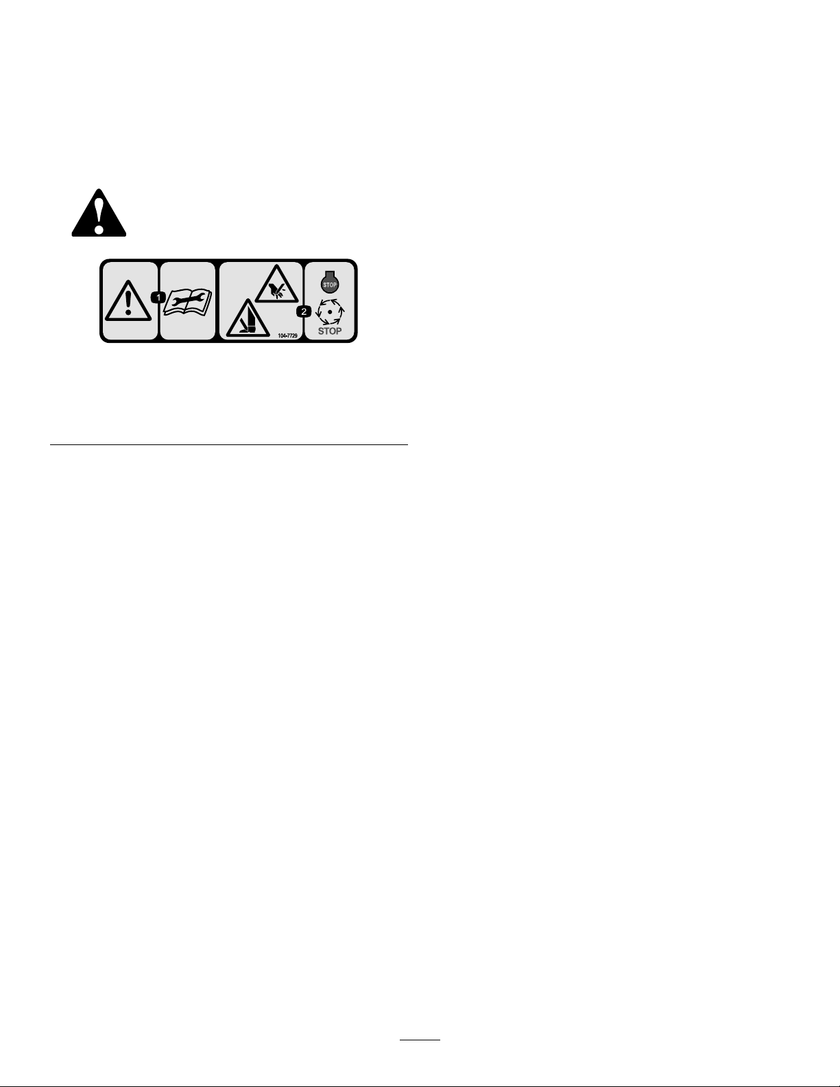
SafetyandInstructionalDecals
Safetydecalsandinstructionsareeasilyvisibletotheoperatorandarelocatednearanyareaofpotential
danger.Replaceanydecalthatisdamagedorlost.
104–7729
•Usefull-widthrampsforloadingthemachineintoa
traileroratruck.
•Tiethemachinedownsecurelyusingstraps,chains,cable,
orropes.Boththefrontandtherearstrapsshouldbe
directeddownandoutwardfromthemachine.
1.Warning—readthe
instructionsbefore
servicingorperforming
maintenance.
2.Cutting/dismemberment
hazard;handorfoot—stop
theengineandwaitfor
movingpartstostop.
4
Page 5
Setup
G016936
1
2
4
5
6
3
G020075
MediaandAdditionalParts
Description
Ballstud2Mountthistotheroller.
Operator'sManual
Partscatalog1
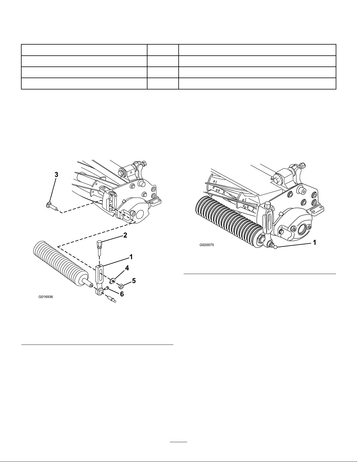
InstallingtheRoller
Thecuttingunitisshippedwithoutafrontroller.Obtain
arollerfromyourdealerandinstallitonthecuttingunit,
asfollows:
1.Removetheplowbolt,washer,andangenutsecuring
oneoftheheight-of-cutarmstothecuttingunitside
plate(Figure3).
Qty.
1
Readbeforeinstallingandoperatingthecuttingunit.
Usethistoreferencepartnumbers.
7.Tightentheroller-mountingscrews(Figure3).
8.Adjusttothedesiredheight-of-cutandtightenthe
height-of-cutarmmountingfasteners.
InstallingtheBallStuds
Installaballstudoneachendofthefrontroller(Figure4).
Use
Figure3
1.Height-of-cutarm
2.Adjustingscrew5.Flangenut
3.Plowbolt6.Roller-mountingscrew
2.Loosentheroller-mountingscrewsintheheight-of-cut
arms(Figure3).
3.Slidetherollershaftintotheheight-of-cutarmonthe
oppositeendofthecuttingunit(Figure3).
4.Slidetheheight-of-cutarmontotherollershaft(Figure
3).
5.Looselysecuretherollertothecuttingunitwiththe
height-of-cutarmandfastenerspreviouslyremoved
(Figure3).
6.Centertherollerbetweentheheight-of-cutarms.
4.Washer
Figure4
1.Ballstud
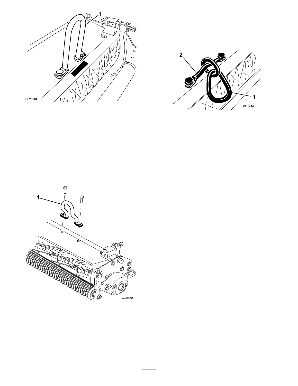
InstallingtheHoopLink,Offset
Link,orChainLink
Forcuttingunitsmountingonatractionunitwithaserial
numberpriorto240000001,obtainandinstalltheproper
liftlinkasfollows:
Note:The2boltsusedtomounttheliftlinkareshipped
installedonthecuttingunit.
•ForGreensmaster3120and3150tractionunits,install
thehooplink(PartNo.105-5740)suppliedwiththe
tractionunit.
Installthehooplinktothetopofthecuttingunitwith2
bolts.Torquetheboltsto34to40N∙m(25to30ft-lb)
(Figure5).
5
Page 6
G020064
Figure5
G020065
g011932
1
2
Installthechainlink(Figure7)tothetopofthecutting
unitwiththemountingbracketand2bolts.Torquethe
boltsto34to40N∙m(25to30ft-lb).
Note:Whenmountingthecuttingunittothetraction
unit,hookthewiderendofthechainlinktotheliftarm.
1.Hooplink
•FortheGreensmaster3250-Dtractionunits,installthe
offsetlink(PartNo.110-2397)suppliedwiththetraction
unit.
Installtheoffsetlink(Figure6)tothetopofthecutting
unitwith2bolts.Torquetheboltsto34to40N∙m(25
to30ft-lb).
Important:Positionthelifthookoffsettowardsthe
frontofthecuttingunit.
Figure7
1.Chainlink
2.Mountingbracket
RepositioningtheCounter
Weights
Thecuttingunitsareshippedwiththecounterweight
mountedtotheleftendandthemotormounttotherightend
ofthecuttingunit.T ochangethecuttingunittodifferent
positions,proceedasfollows:
Important:Wheneveryouneedtotipthecuttingunit
onitsside,ensurethatyoupropituptoavoiddamaging
thebedbar-adjustingscrews;refertoSupportingthe
CuttingUnit(page9)
1.Removethe2boltssecuringthecounterweighttothe
leftendofthecuttingunit.Removethecounterweight
(Figure9).
2.Removethe2Allenheadscrewssecuringthemotor
mounttotheleftendofthecuttingunit.Removethe
motormount(Figure8).
Figure6
1.Offsetlifthook
•OptionallyfortheGreensmaster3250-Dtractionunits,
youcaninstallthechainLink(PartNo.106-2601)and
mountingbracket(PartNo.105-5738)availablefrom
yourT oroDistributor.
3.Applygreasetotheinsidediameterofthedrivespline
(Figure8).
4.Ontheleftendofthecuttingunit,applyalightcoating
ofoiltotheO-ringandinstallthemotormountwith
the2Allenheadscrewspreviouslyremoved(Figure8).
Torquethescrewsto16to20N∙m(12to15ft-lb).
6
Page 7

Figure8
1.Drivespline3.Allenheadscrew
2.Motormount
5.Ontherightendofthecuttingunit,applyalight
coatingofoiltotheO-ringandinstallthecounter
weightwiththeboltspreviouslyremoved(Figure9).
Torquethescrewsto16to20N∙m(12to15ft-lb).
Figure9
1.Counterweight
AdjustingtheCuttingUnit
1.Supportthecuttingunit;refertoSupportingthe
CuttingUnit(page9).
2.Adjustthebedknifetothereel;refertoAdjustingthe
BedknifetotheReel(page9).
3.Adjusttherearrollerheight;refertoAdjustingthe
Rear-RollerHeight(page10).
4.Adjusttheheightofcut;refertoAdjustingtheHeight
ofCut(page11).
5.Adjustthecut-offbar;refertoAdjustingtheCut-Off
Bar(page12).
7
Page 8

ProductOverview
Specications
Tractors
HeightofCutAdjustonthefrontrollerusing2verticalscrewsandheld2lockingscrews.
Height-of-CutRangeStandardbenchheight-of-cutrangeis1.6mm(0.062inch)to12.7mm(0.500inch).Bench
CuttingWidth53cm(21inches)
ReelBearingsT wosealedstainlesssteel,deepgrooveballbearings
Rollers
BedknifeReplaceablesingleedged,highcarbonsteelbedknifeisfastenedtoamachinedcastiron
BedknifeAdjustmentDual-screwadjustmenttothereel;detentscorrespondingto0.018mm(0.0007inch)
GrassShieldNon-adjustableshieldwithadjustablecut-offbartoimprovegrassdischargefromreelin
Counterweight
NetWeight
Greensmaster3120,3150,3250-D,and3150-QTractionUnits.
height-of-cutrangewiththeHighHeightofCutKitinstalledis7mm(0.285inch)to25mm
(1.00inch).Effectiveheightofcutmayvarydependingonturfconditions,typeofbedknife,
rollers,andattachmentsinstalled.
Therearrollerisa5.1cm(2inch)diametersteelfullroller.
bedbarwith13screws
bedknifemovementforeachindexedposition
wetconditions
Acastironweightmountedoppositetothedrivemotorbalancesthecuttingunit.
8Blade—30kg(65lb),11Blade—31kg(68lb),14Blade—32kg(71lb)
Attachments/Accessories
AselectionofToroapprovedattachmentsandaccessoriesisavailableforusewiththemachinetoenhanceandexpand
itscapabilities.ContactyourAuthorizedServiceDealerorDistributororgotowww.Toro.comforalistofallapproved
attachmentsandaccessories.
TobestprotectyourinvestmentandmaintainoptimalperformanceofyourToroequipment,countonTorogenuineparts.
Whenitcomestoreliability,Torodeliversreplacementpartsdesignedtotheexactengineeringspecicationofourequipment.
Forpeaceofmind,insistonT orogenuineparts.
Operation
RefertoyourtractionunitOperator’sManualfordetailedoperationinstructions.Beforeusingthecuttinguniteachday,adjustthe
bedknife;refertoAdjustingtheBedknifeDaily(page9).Testthequalityofcutbycuttingatestswathbeforeusingthecutting
unitonagreentoensurethatthenishedcutiscorrect.
8
Page 9

Maintenance
g026076
1
2
Note:Determinetheleftandrightsidesofthemachine
fromthenormaloperatingposition.
SupportingtheCuttingUnit
Wheneveryouneedtotipthecuttingunittoexposethe
bedknife/reel,propuptherearofthecuttingunittoensure
thatthenutsonthebackendofthebedbar-adjustingscrews
arenotrestingontheworksurface(Figure10).
Figure10
1.Prop(notprovided)
AdjustingtheBedknife-to-Reel Contact
AdjustingtheBedknifeDaily
Priortomowingeachday,orasrequired,verifyproper
bedknife-to-reelcontact.Performthisprocedureeven
thoughqualityofcutisacceptable.
1.Lowerthecuttingunitsontoahardsurface,shutoff
theengine,andremovetheignitionkey.
2.Slowlyrotatethereelinareversedirection,listening
forreel-to-bedknifecontact.
•Ifnocontactisevident,adjustthebedknifeas
follows
A.Turnthebedbaradjustingscrewsclockwise
(Figure11),1clickatatime,untilyoufeeland
hearlightcontact.
Note:Thebedbaradjustingscrewshave
detentscorrespondingto0.018mm(0.0007
inch)bedknifemovementforeachindexed
position.
2.Bedbar-adjusting-screw
nut(2)
Figure11
1.Bedbaradjustingscrew
B.Insertalongstripofcuttingperformance
paper(ToroPartNo.125-5610)between
thereelandbedknife,perpendiculartothe
bedknife(Figure12),thenslowlyrotatethe
reelforward;itshouldcutthepaper;ifnot,
repeatstepsAandBuntilitdoes.
•Ifexcessivecontact/reeldragisevident,backlap,
refacethefrontofthebedknife,orgrindthecutting
unittoachievethesharpedgesneededforprecision
cutting(RefertotheToroManualforSharpeningReel
andRotaryMowers,FormNo.09168SL).
Important:Lightcontactispreferredatall
times.Ifyoudonotmaintainlightcontact,
thebedknife/reeledgeswillnotsufciently
self-sharpen,anddullcuttingedgeswillresultafter
aperiodofoperation.Ifyoumaintainexcessive
contact,bedknife/reelwearwillbeaccelerated,
unevenwearcanresult,andthequalityofcutmay
decline.
Note:Asthereelbladescontinuetorunagainstthe
bedknife,aslightburrwillappearonthefrontcutting
edgesurfacealongthefulllengthofthebedknife.
Occasionallyrunaleacrossthefrontedgetoremove
thisburrtoimprovecutting.
Afterextendedrunning,aridgewilleventuallydevelop
atbothendsofthebedknife.Roundoffthesenotches
orlethemushwiththecuttingedgeofthebedknife
toensuresmoothoperation.
AdjustingtheBedknifetotheReel
Usethisprocedureduringinitialcutting-unitsetupandafter
grinding,backlapping,ordisassemblingthereel.Thisisnota
dailyadjustment.
1.Positionthecuttingunitonaat,levelworksurface.
2.Tipthecuttingunittoexposethebedknifeandreel.
9
Page 10

Note:Ensurethatthenutsonthebackofthebedbar
adjustingscrewsarenotrestingontheworksurface
(Figure10).
3.Rotatethereelsothat1ofthebladescrossesthe
bedknifeedgebetweentherstandsecondbedknife
screwheadslocatedontherightsideofthecuttingunit.
4.Makeanidentifyingmarkonthebladewhereitcrosses
thebedknifeedge.
Note:Thiswillmakelateradjustmentseasier.
5.Inserta0.05mm(0.002inch)shimbetweentheblade
andthebedknifeedgeatthepointmarkedinstep4.
6.Turntherightbedbaradjustingscrew(Figure11)until
youfeellightpressureontheshimwhenslidingit
side-to-side.Removetheshim.
7.Fortheleftsideofthecuttingunit,slowlyrotatethe
reelsothattheclosestbladecrossesthebedknifeedge
betweentherstandsecondscrewheads.
8.Repeatsteps4through6fortheleftsideofthecutting
unitandleftbedbaradjustingscrew.
9.Repeatsteps5and6untilthereislightpressureatthe
contactpointsonboththeleftandrightsidesofthe
cuttingunit.
10.Toobtainlightcontactbetweenthereelandbedknife,
turneachbedbaradjustingscrewclockwise3clicks.
Note:Ifexcessivecontact/reeldragisevident,backlap,
refacethefrontofthebedknife,orgrindthecuttingunitto
achievethesharpedgesneededforprecisioncutting(Refer
totheToroManualforSharpeningReelandRotaryMowers,Form
No.09168SL).
AdjustingtheRear-Roller Height
Dependingonyourdesiredheight-of-cutrange,youneedto
adjusttherear-rollerbrackets(Figure13orFigure14)tothe
loworhighposition:
•Positionthespacerabovethesideplate-mountingange
(factorysetting)whentheheight-of-cutsettingsrange
from1.5mmto6mm(1/16inchto1/4inch)asshown
inFigure13.
Note:Eachclickonthebedbaradjustingscrewmoves
thebedknife0.018mm(0.0007inches).Donotover
tightentheadjustingscrews.
Turningtheadjustingscrewclockwisemovesthe
bedknifeedgeclosertothereel.Turningtheadjusting
screwcounterclockwisemovesthebedknifeedgeaway
fromthereel.
11.Insertalongstripofcuttingperformancepaper(Toro
PartNo.125-5610)betweenthereelandbedknife,
perpendiculartothebedknife(Figure12),thenslowly
rotatethereelforward;itshouldcutthepaper;ifnot,
turneachbedbaradjustingscrewclockwise1clicksand
repeatthisstepuntilitcutsthepaper.
Figure13
1.Spacer
2.Sideplate-mountingange
3.Rollerbracket
•Positionthespacerbelowthesideplate-mountingange
whentheheight-of-cutsettingsrangefrom3mmto25
mm(1/8inchto1inch)asshowninFigure14.
Figure14
1.Sideplate-mountingange
2.Spacer
3.Rollerbracket
Figure12
1.Raisetherearofthecuttingunitandplaceablock
underthebedknife.
2.Removethe2nutssecuringeachrollerbracketand
spacertoeachsideplatemountingange.
3.Lowertherollerandscrewsfromthesideplate
mountingangesandspacers.
10
Page 11

4.Placethespacersontothescrewsaboveorbelowthe
G020074
rollerbrackets,asrequired(Figure13orFigure14).
5.Securetherollerbracketandspacerstotheunderside
ofthemountingangeswiththenutspreviously
removed.
Note:Thepositionoftherearrollertothereeliscontrolled
bythemachiningtolerancesoftheassembledcomponents
andparallelingisnotrequired.
Figure15
AdjustingtheHeightofCut
Usethefollowingcharttodeterminewhichbedknifeisbest
suitedforthedesiredheightofcut.
Bedknife
Edgemax
Micro-cut
(Standard)
Edgemax
Tournament
(Optional)
Micro-cut
(Optional)
Tournament
(Optional)
Extended
Micro-cut
(Optional)
Extended
Tournament
(Optional)
Low-cut
(Optional)
High-cut
(Optional)
Fairway
(Optional)
Fairway
EdgeMax
(optional)
PartNo.
115-1880
115-1881
93-4262
93-4263
108-4303
108-4302
93-4264
94-6392
63-8600
112–7475
Height-of-Cut
1.5to4.7mm(0.062to
0.188inch)
3.1to12.7mm(0.125to
0.500inch)
1.5to4.7mm(0.062to
0.188inch)
3.1to12.7mm(0.125to
0.500inch)
1.5to4.7mm(0.062to
0.188inch)
3.1to12.7mm(0.125to
0.500inch)
4.7to25.4mm(0.188to
1.00inch)
7.9to25.4mm(0.312to
1.00inch)
9.5to25.4mm(0.375to
1.00inch)
9.5to25.4mm(0.375to
1.00inch)
1.Gaugebar
2.Height-adjustingscrew
3.Nut
2.Tightenthenut.
AdjustingtheHeightofCut
1.Loosenthelocknutssecuringtheheight-of-cutarmsto
thecutting-unitsideplates(Figure16).
Figure16
1.Height-of-cutarm
2.Locknut
3.Adjustingscrew
Note:Forheightsofcutgreaterthan9.5mm(0.375inch),
installthehigh-height-of-cutkit.
AdjustingtheHeight-of-CutGauge
Beforeadjustingtheheightofcut,settheheight-of-cutgauge
asfollows:
1.Loosenthenutonthegaugebarandsettheadjusting
screwtothedesiredheightofcut(Figure15).
Note:Thedistancebetweenthebottomofthescrew
headandthefaceofbaristheheightofcut.
2.Hookthescrewheadoftheheight-of-cutgaugeonto
therightsideofthecuttingedgeofthebedknifeand
resttherearendofthebarontotherearoftheroller
(Figure17).
11
Page 12

1
g014643
Figure18
Figure17
1.Gaugebar
3.Rotatetheadjustingscrewuntiltherollercontactsthe
frontofthegaugebar.
4.Repeatsteps2and3fortheleftside.
5.Adjustbothendsoftherolleruntiltheentirerolleris
paralleltothebedknife.
Important:Whensetproperly,therearandfront
rollerswillcontactthegaugebarandthescrew
willbesnugagainstthebedknife.Thisensures
thattheheightofcutisidenticalatbothendsof
thebedknife.
6.Tightenthenutstosecuretheadjustmentenoughto
removeplayfromthewasher.
7.Verifythattheheight-of-cutsettingiscorrect;repeat
thisprocedureifnecessary.
AdjustingtheCut-OffBar
Adjustthecut-offbartoensurethattheclippingsarecleanly
dischargedfromthereelarea,asfollows:
Note:Thebarisadjustabletocompensateforchangesin
turfconditions.Adjustthebarclosertothereelwhentheturf
isextremelydry.Bycontrast,adjustthebarfurtherawayfrom
thereelwhentheturfconditionsarewet.Thebarshouldbe
paralleltothereeltoensureoptimumperformance.Adjustit
afterthereelissharpenedonareelgrinder.
1.Cut-offbar
2.Inserta1.5mm(0.060inch)feelergaugebetweenthe
topofthereelandthebarthentightenthescrews.
Important:Ensurethatthebarandreelareequal
distanceapartacrossthecompletereel.
Note:Adjustthegapasneededforyourturf
conditions.
ServicingtheBedbar
Onlyaproperlytrainedmechanicshouldservicethebedbar
andbedknifetopreventdamagetothereel,bedbar,or
bedknife.Ideally,takethecuttingunittoyourAuthorized
ToroDistributorforservice.RefertotheServiceManualfor
yourtractionunitforcompleteinstructions,specialtools,
anddiagramsforservicingthebedknife.Shouldyouever
needtoremoveorassemblethebedbaryourself,instructions
areprovidedbelow ,asarethespecicationsforservicingthe
bedknife.
Important:Alwaysfollowthebedknifeprocedures
detailedinyour
bedknife.Failuretoinstallandgrindthebedknife
correctlycanleadtodamagetothereel,bedbar,or
bedknife.
RemovingtheBedbar
1.Turnthebedbaradjustingscrew ,counterclockwise,to
backthebedknifeawayfromthereel(Figure19).
Ser vice Man ual
whenservicingthe
1.Loosenthescrewssecuringthetopbar(Figure18)to
thecuttingunit.
12
Page 13

Figure19
g020056
Figure21
1.Bedbarbolt3.Nylonwasher
2.Nut
4.Steelwasher
1.Bedbar-adjustingscrew3.Bedbar
2.Spring-tensionnut
4.Washer
2.Backoutthespring-tensionnutuntilthewasherisno
longertensionedagainstthebedbar(Figure19).
3.Oneachsideofthemachine,loosenthelocknut
securingthebedbarbolt(Figure20).
Figure20
1.Bedbarbolt2.Locknut
4.Removeeachbedbarboltallowingthebedbartobe
pulleddownwardandremovedfromthecuttingunit
(Figure21).
AssemblingtheBedbar
1.Installthebedbar,positioningthemountingears
betweenthewashersandthebedbar-adjustingscrew
(Figure22).
2.Securethebedbartoeachsideplatewiththebedbar
bolts(nutsonbolts)and3washers(6total).
3.Positionanylonwasheroneachsideoftheside-plate
boss.Placeasteelwasheroutsideeachofthenylon
washers(Figure21).
4.Torquethebedbarboltsto27to36N∙m(240to320
inch-lb).
5.Tightenthelocknutsuntilyouremovetheendplay
fromsteelwashers,butyouareabletorotatethemby
hand.Thewashersontheinsidemayhaveagap.
Important:Donotovertightenthelocknutsor
theywilldeectthesideplates.
6.Tightenthespringtensionnutuntilthespringis
collapsed,thenbackitoff1/2turn(Figure22).
Accountforthe2nylonwashersand1steelwasheron
eachendofthebedbar(Figure21).
Figure22
1.Spring-tensionnut2.Spring
13
Page 14

7.Adjustthebedknifetothereel;refertoAdjustingthe
BedknifetotheReel(page9).
BedknifeSpecications
BedknifeTypes
Figure23
1.Standardbedknife:42.9
mm(1.689inches)
BedknifeScrews
Torque:23to28N∙m(200to250in-lb)
Installationtool:TOR510880
Installationorder:
BedknifeGrindingSpecications
2.Extendedbedknife:47.7
mm(1.876inches)
Figure24
BacklappingtheCuttingUnit
DANGER
Contactwiththereelorothermovingpartscan
resultinpersonalinjury.
Keepngers,hands,andclothingawayfromthe
reelsorothermovingparts.
•Stayawayfromthereelwhilebacklapping.
•Neveruseashorthandledpaintbrushfor
backlapping.PartNo.29-9100Handleassembly
completeorindividualpartsareavailablefrom
yourlocalAuthorizedT oroDistributor.
1.Positionthemachineonaclean,levelsurface,lower
thecuttingunits,stoptheengine,engagetheparking
brake,andremovetheignitionkey.
2.Removethereelmotorsfromthecuttingunitsand
disconnectandremovethecuttingunitsfromthelift
arms.
3.Connectthebacklappingmachinetothecuttingunit
byinsertingapieceof3/8inchsquarestockintothe
splinedcouplingintheendofthecuttingunit.
Note:Additionalinstructionsandprocedureson
BacklappingareavailableinyourtractionunitOperator’ s
ManualandtheToroSharpeningReelandRotaryMowers
Manual,FormNumber80-300PT.
Note:Forabettercuttingedge,runaleacrossthe
frontfaceofthebedknifeandreelwhenthelapping
operationiscompleted.Thiswillremoveanyburrsor
roughedgesthatmayhavebuiltuponthecuttingedge.
Figure25
1.Reliefangle4.Frontface
2.Topface
3.Removeburr
Standardbedknifereliefangle3°
Extendedbedknifereliefangle7°
FrontAngle(allbedknife
types)
FrontAngleRange
5.Frontangle
13°
13°to17°
14
Page 15

Notes:
15
Page 16

Notes:
16
Page 17

Notes:
17
Page 18

DeclarationofIncorporation
TheT oroCompany,811 1LyndaleAve.South,Bloomington,MN,USAdeclaresthatthefollowingunit(s)
conform(s)tothedirectiveslisted,wheninstalledinaccordancewiththeaccompanyinginstructionsontocertain
ToromodelsasindicatedontherelevantDeclarationsofConformity.
ModelNo.
04652316000001andUp8-BladeDPAReelMower
04654316000001andUp11-BladeDP AReelMower
04656316000001andUp14-BladeDP AReelMower
SerialNo.
ProductDescriptionInvoiceDescription
8BLADECUTTINGUNIT
NGDPA
11BLADECUTTING
UNITNGDPA
14BLADECUTTING
UNITNGDPA
GeneralDescription
8-BladeDPAReelMower
11-BladeDP AReelMower
14-BladeDPAReelMower
Directive
2006/42/EC,
2000/14/EC
2006/42/EC,
2000/14/EC
2006/42/EC,
2000/14/EC
RelevanttechnicaldocumentationhasbeencompiledasrequiredperPartBofAnnexVIIof2006/42/EC.
Wewillundertaketotransmit,inresponsetorequestsbynationalauthorities,relevantinformationonthispartly
completedmachinery.Themethodoftransmissionshallbeelectronictransmittal.
ThismachineryshallnotbeputintoserviceuntilincorporatedintoapprovedToromodelsasindicatedonthe
associatedDeclarationofConformityandinaccordancewithallinstructions,wherebyitcanbedeclaredin
conformitywithallrelevantDirectives.
Certied:EUTechnicalContact:
MarcVermeiren
ToroEuropeNV
B-2260Oevel-Westerloo
Belgium
DavidKlisTel.003214562960
Sr.EngineeringManager
811 1LyndaleAve.South
Bloomington,MN55420,USA
October9,2015
Fax003214581911
18
Page 19

InternationalDistributorList
Distributor:
AgrolancKft
AsianAmericanIndustrial(AAI)
B-RayCorporation
BrisaGoodsLLC
CascoSalesCompany
CeresS.A.CostaRica
CSSCTurfEquipment(pvt)Ltd.SriLanka
CyrilJohnston&Co.
CyrilJohnston&Co.RepublicofIreland
FatDragon
FemcoS.A.Guatemala
FIVEMANSNew-T echCo.,LtdChina
ForGarderOU
G.Y .K.CompanyLtd.
GeomechanikiofAthensGreece
GolfinternationalTurizm
HakoGroundandGardenSweden
HakoGroundandGarden
HayterLimited(U.K.)
HydroturfInt.CoDubai
HydroturfEgyptLLC
IrrimacPortugal351212388260T oroEuropeNVBelgium3214562960
IrrigationProductsInt'lPvtLtd.India00914424494387ValtechMorocco212537663636
JeanHeybroekb.v.Netherlands31306394611VictusEmakPoland48618238369
Country:
Hungary3627539640
HongKong85224977804
Korea82325512076
Mexico12104952417
PuertoRico7877888383
NorthernIreland442890813121
China
Estonia3723846060
Japan81726325861Riversa
Turkey902163365993
Norway4722907760
UnitedKingdom441279723444
UnitedArabEmirates97143479479T-MarktLogisticsLtd.Hungary3626525500
Egypt2025194308ToroAustraliaAustralia61395807355
PhoneNumber:Distributor:
MaquiverS.A.Colombia
MaruyamaMfg.Co.Inc.
Mountelda.s.CzechRepublic
Mountelda.s.Slovakia
5062391138
94112746100
442890813121ParklandProductsLtd.NewZealand6433493760
8861080841322
5024423277
86-10-63816136
30109350054
4635100000
MunditolS.A.
NormaGarden
OslingerTurfEquipmentSA
OyHakoGroundandGardenAb
Perfetto
PratoverdeSRL.
Prochaska&Cie
RTCohen2004Ltd.
LelyTurfcare
Lely(U.K.)Limited
SolvertS.A.S.
SpyprosStavrinidesLimitedCyprus
SurgeSystemsIndiaLimited
Country:
Japan81332522285
Argentina541 148219999
Russia749541 16120
Ecuador59342396970
Finland35898700733
Poland48618208416
Italy390499128128
Austria4312785100
Israel97298617979
Spain
Denmark4566109200
UnitedKingdom441480226800
France33130817700
India911292299901
PhoneNumber:
5712364079
420255704220
420255704220
34952837500
35722434131
EuropeanPrivacyNotice
TheInformationToroCollects
ToroWarrantyCompany(Toro)respectsyourprivacy.Inordertoprocessyourwarrantyclaimandcontactyouintheeventofaproductrecall,weaskyou
tosharecertainpersonalinformationwithus,eitherdirectlyorthroughyourlocalT orocompanyordealer.
TheT orowarrantysystemishostedonserverslocatedwithintheUnitedStateswhereprivacylawmaynotprovidethesameprotectionasapplies
inyourcountry.
BYSHARINGYOURPERSONALINFORMATIONWITHUS,YOUARECONSENTINGTOTHEPROCESSINGOFYOURPERSONALINFORMATION
ASDESCRIBEDINTHISPRIV ACYNOTICE.
TheWayT oroUsesInformation
Toromayuseyourpersonalinformationtoprocesswarrantyclaims,tocontactyouintheeventofaproductrecallandforanyotherpurposewhichwetell
youabout.ToromayshareyourinformationwithT oro'safliates,dealersorotherbusinesspartnersinconnectionwithanyoftheseactivities.Wewillnot
sellyourpersonalinformationtoanyothercompany.Wereservetherighttodisclosepersonalinformationinordertocomplywithapplicablelawsand
withrequestsbytheappropriateauthorities,tooperateoursystemsproperlyorforourownprotectionorthatofotherusers.
RetentionofyourPersonalInformation
Wewillkeepyourpersonalinformationaslongasweneeditforthepurposesforwhichitwasoriginallycollectedorforotherlegitimatepurposes
(suchasregulatorycompliance),orasrequiredbyapplicablelaw .
Toro'sCommitmenttoSecurityofYourPersonalInformation
Wetakereasonableprecautionsinordertoprotectthesecurityofyourpersonalinformation.Wealsotakestepstomaintaintheaccuracyandcurrent
statusofpersonalinformation.
AccessandCorrectionofyourPersonalInformation
Ifyouwouldliketorevieworcorrectyourpersonalinformation,pleasecontactusbyemailatlegal@toro.com.
AustralianConsumerLaw
AustraliancustomerswillnddetailsrelatingtotheAustralianConsumerLaweitherinsidetheboxoratyourlocalToroDealer.
374-0269RevK
Page 20

TheT oroWarranty
ATwo-YearLimitedWarranty
ConditionsandProductsCovered
TheToroCompanyanditsafliate,T oroWarrantyCompany,pursuant
toanagreementbetweenthem,jointlywarrantyourT oroCommercial
product(“Product”)tobefreefromdefectsinmaterialsorworkmanship
fortwoyearsor1500operationalhours*,whicheveroccursrst.This
warrantyisapplicabletoallproductswiththeexceptionofAerators
(refertoseparatewarrantystatementsfortheseproducts).Wherea
warrantableconditionexists,wewillrepairtheProductatnocosttoyou
includingdiagnostics,labor,parts,andtransportation.Thiswarranty
beginsonthedatetheProductisdeliveredtotheoriginalretailpurchaser .
*Productequippedwithanhourmeter.
InstructionsforObtainingWarrantyService
YouareresponsiblefornotifyingtheCommercialProductsDistributoror
AuthorizedCommercialProductsDealerfromwhomyoupurchasedthe
Productassoonasyoubelieveawarrantableconditionexists.Ifyouneed
helplocatingaCommercialProductsDistributororAuthorizedDealer,or
ifyouhavequestionsregardingyourwarrantyrightsorresponsibilities,
youmaycontactusat:
ToroCommercialProductsServiceDepartment
ToroWarrantyCompany
811 1LyndaleAvenueSouth
Bloomington,MN55420-1196
952–888–8801or800–952–2740
E-mail:commercial.warranty@toro.com
OwnerResponsibilities
AstheProductowner,youareresponsibleforrequiredmaintenanceand
adjustmentsstatedinyourOperator'sManual.Failuretoperformrequired
maintenanceandadjustmentscanbegroundsfordisallowingawarranty
claim.
ItemsandConditionsNotCovered
Notallproductfailuresormalfunctionsthatoccurduringthewarranty
periodaredefectsinmaterialsorworkmanship.Thiswarrantydoesnot
coverthefollowing:
•Productfailureswhichresultfromtheuseofnon-T ororeplacement
parts,orfrominstallationanduseofadd-on,ormodiednon-Toro
brandedaccessoriesandproducts.Aseparatewarrantymaybe
providedbythemanufactureroftheseitems.
•Productfailureswhichresultfromfailuretoperformrecommended
maintenanceand/oradjustments.Failuretoproperlymaintainyour
ToroproductpertheRecommendedMaintenancelistedinthe
Operator’sManualcanresultinclaimsforwarrantybeingdenied.
•ProductfailureswhichresultfromoperatingtheProductinanabusive,
negligent,orrecklessmanner.
•Partssubjecttoconsumptionthroughuseunlessfoundtobedefective.
Examplesofpartswhichareconsumed,orusedup,duringnormal
Productoperationinclude,butarenotlimitedto,brakepadsand
linings,clutchlinings,blades,reels,rollersandbearings(sealedor
greasable),bedknives,sparkplugs,castorwheelsandbearings,tires,
lters,belts,andcertainsprayercomponentssuchasdiaphragms,
nozzles,andcheckvalves,etc.
•Failurescausedbyoutsideinuence.Conditionsconsideredtobe
outsideinuenceinclude,butarenotlimitedto,weather,storage
practices,contamination,useofunapprovedfuels,coolants,lubricants,
additives,fertilizers,water,orchemicals,etc.
•Failureorperformanceissuesduetotheuseoffuels(e.g.gasoline,
diesel,orbiodiesel)thatdonotconformtotheirrespectiveindustry
standards.
•Normalnoise,vibration,wearandtear ,anddeterioration.
•Normal“wearandtear”includes,butisnotlimitedto,damagetoseats
duetowearorabrasion,wornpaintedsurfaces,scratcheddecalsor
windows,etc.
Parts
Partsscheduledforreplacementasrequiredmaintenancearewarranted
fortheperiodoftimeuptothescheduledreplacementtimeforthatpart.
Partsreplacedunderthiswarrantyarecoveredforthedurationofthe
originalproductwarrantyandbecomethepropertyofT oro.T orowillmake
thenaldecisionwhethertorepairanyexistingpartorassemblyorreplace
it.T oromayuseremanufacturedpartsforwarrantyrepairs.
DeepCycleandLithium-IonBatteryWarranty:
DeepcycleandLithium-Ionbatterieshaveaspeciedtotalnumberof
kilowatt-hourstheycandeliverduringtheirlifetime.Operating,recharging,
andmaintenancetechniquescanextendorreducetotalbatterylife.Asthe
batteriesinthisproductareconsumed,theamountofusefulworkbetween
chargingintervalswillslowlydecreaseuntilthebatteryiscompletelyworn
out.Replacementofwornoutbatteries,duetonormalconsumption,
istheresponsibilityoftheproductowner.Batteryreplacementmaybe
requiredduringthenormalproductwarrantyperiodatowner’sexpense.
Note:(Lithium-Ionbatteryonly):ALithium-Ionbatteryhasapartonly
proratedwarrantybeginningyear3throughyear5basedonthetime
inserviceandkilowatthoursused.RefertotheOperator'sManualfor
additionalinformation.
MaintenanceisatOwner’sExpense
Enginetune-up,lubrication,cleaningandpolishing,replacementoflters,
coolant,andcompletingrecommendedmaintenancearesomeofthe
normalservicesT oroproductsrequirethatareattheowner’sexpense.
GeneralConditions
RepairbyanAuthorizedToroDistributororDealerisyoursoleremedy
underthiswarranty.
NeitherTheToroCompanynorToroWarrantyCompanyisliablefor
indirect,incidentalorconsequentialdamagesinconnectionwiththe
useoftheToroProductscoveredbythiswarranty,includingany
costorexpenseofprovidingsubstituteequipmentorserviceduring
reasonableperiodsofmalfunctionornon-usependingcompletion
ofrepairsunderthiswarranty.ExceptfortheEmissionswarranty
referencedbelow,ifapplicable,thereisnootherexpresswarranty.All
impliedwarrantiesofmerchantabilityandtnessforusearelimitedto
thedurationofthisexpresswarranty.
Somestatesdonotallowexclusionsofincidentalorconsequential
damages,orlimitationsonhowlonganimpliedwarrantylasts,sotheabove
exclusionsandlimitationsmaynotapplytoyou.Thiswarrantygivesyou
speciclegalrights,andyoumayalsohaveotherrightswhichvaryfrom
statetostate.
Noteregardingenginewarranty:
TheEmissionsControlSystemonyourProductmaybecoveredby
aseparatewarrantymeetingrequirementsestablishedbytheU.S.
EnvironmentalProtectionAgency(EP A)and/ortheCaliforniaAirResources
Board(CARB).Thehourlimitationssetforthabovedonotapplytothe
EmissionsControlSystemWarranty.RefertotheEngineEmissionControl
WarrantyStatementsuppliedwithyourproductorcontainedintheengine
manufacturer’sdocumentationfordetails
CountriesOtherthantheUnitedStatesorCanada
CustomerswhohavepurchasedT oroproductsexportedfromtheUnitedStatesorCanadashouldcontacttheirT oroDistributor(Dealer)toobtain
guaranteepoliciesforyourcountry ,province,orstate.IfforanyreasonyouaredissatisedwithyourDistributor'sserviceorhavedifcultyobtaining
guaranteeinformation,contacttheT oroimporter.
374-0253RevD
 Loading...