

Toro 04613, 04614, 04615, Greensmaster 3300 Series, Greensmaster 3400 Series Operator's Manual
Page 1
FormNo.3376-576RevB
8,11,and14-BladeDPAReel
Mower
Greensmaster
®
3300/3400SeriesTraction
Unit
ModelNo.04613—SerialNo.313000001andUp
ModelNo.04614—SerialNo.313000001andUp
ModelNo.04615—SerialNo.313000001andUp
Registeratwww.T oro.com.
OriginalInstructions(EN)
*3376-576*B
Page 2
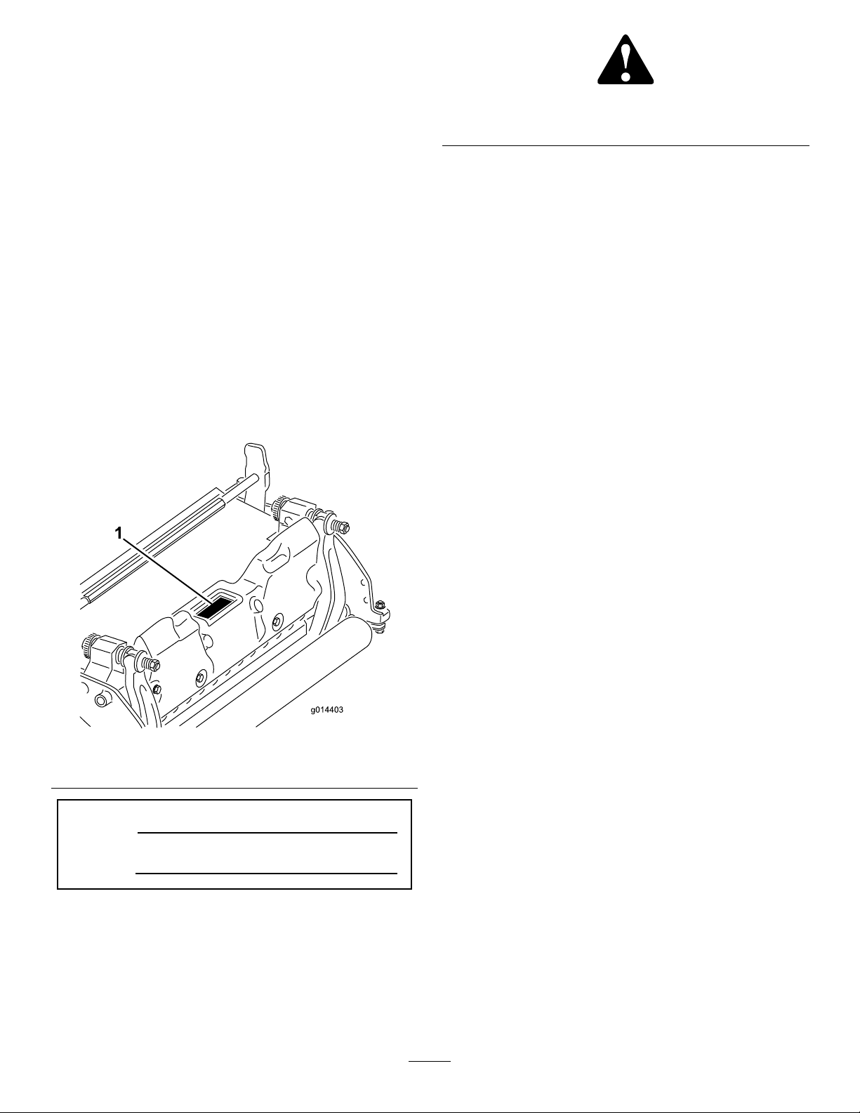
Figure2
Introduction
Thiscuttingunitisdesignedforcuttingturfongreensand
smallfairwaysofgolfcourses.
Readthisinformationcarefullytolearnhowtooperateand
maintainyourproductproperlyandtoavoidinjuryand
productdamage.Youareresponsibleforoperatingthe
productproperlyandsafely.
YoumaycontactTorodirectlyatwww .Toro.comforproduct
andaccessoryinformation,helpndingadealer,ortoregister
yourproduct.
Wheneveryouneedservice,genuineT oroparts,oradditional
information,contactanAuthorizedServiceDealerorToro
CustomerServiceandhavethemodelandserialnumbersof
yourproductready.Figure1identiesthelocationofthe
modelandserialnumbersontheproduct.Writethenumbers
inthespaceprovided.
1.Safetyalertsymbol
Thismanualuses2wordstohighlightinformation.
Importantcallsattentiontospecialmechanicalinformation
andNoteemphasizesgeneralinformationworthyofspecial
attention.
Contents
Introduction..................................................................2
Safety...........................................................................3
SafetyandInstructionalDecals.................................3
Setup............................................................................4
InstallingtheFrontRoller.........................................4
UsingtheCuttingUnitProp......................................4
AdjustingtheBedknifetotheReel.............................4
AdjustingtheRearRoller..........................................5
AdjustingtheHeightofCut......................................5
AdjustingtheCut-OffBar........................................7
ProductOverview..........................................................8
Specications.........................................................8
Attachments/Accessories.........................................8
Operation.....................................................................9
CuttingUnitCharacteristics......................................9
DailyAdjustmentsoftheCuttingUnit........................9
Maintenance.................................................................10
ServicingtheBedbar...............................................10
BacklappingtheReel...............................................11
Figure1
1.Locationofthemodelandserialnumbers
ModelNo.
SerialNo.
Thismanualidentiespotentialhazardsandhassafety
messagesidentiedbythesafetyalertsymbol(Figure2),
whichsignalsahazardthatmaycauseseriousinjuryordeath
ifyoudonotfollowtherecommendedprecautions.
©2014—TheToro®Company
8111LyndaleAvenueSouth
Bloomington,MN55420
Contactusatwww.Toro.com.
2
PrintedintheUSA.
AllRightsReserved
Page 3
Safety
Hazardcontrolandaccidentpreventionaredependent
upontheawareness,concern,andpropertraining
ofthepersonnelinvolvedintheoperation,transport,
maintenance,andstorageofthemachine.Improper
useormaintenanceofthemachinecanresultininjury
ordeath.Toreducethepotentialforinjuryordeath,
complywiththefollowingsafetyinstructions.
•Read,understand,andfollowallinstructionsinthe
tractionunitandcuttingunitOperator’sManualsbefore
operatingthecuttingunit.
•Neverallowchildrentooperatethetractionunitor
cuttingunits.Donotallowadultstooperatetractionunit
orcuttingunitswithoutproperinstruction.Onlytrained
operatorswhohavereadthismanualshouldoperatethe
tractionunitorcuttingunits.
•Neveroperatethecuttingunitswhenundertheinuence
ofdrugsoralcohol.
•Keepallshieldsandsafetydevicesinplace.Ifashield,
safetydeviceordecalisillegibleordamaged,repairor
replaceitbeforeoperationiscommenced.Alsotighten
anyloosenuts,bolts,andscrewstoensurecuttingunitis
insafeoperatingcondition.
•Alwayswearsubstantialshoes.Donotoperatecutting
unitswhilewearingsandals,tennisshoes,sneakers,or
shorts.Also,donotwearloosettingclothingwhich
couldgetcaughtinmovingparts.Alwayswearlongpants
andsubstantialshoes.Wearingsafetyglasses,safetyshoes,
andahelmetisadvisableandrequiredbysomelocal
ordinancesandinsuranceregulations.
•Removealldebrisorotherobjectsthatmightbepicked
upandthrownbythecuttingunitreelblades.Keepall
bystandersawayfromtheworkingarea.
•Ifthecuttingbladesstrikeasolidobjectortheunit
vibratesabnormally,stopandshuttheengineoff.Check
thecuttingunitsfordamagedparts.Repairanydamage
beforerestartingandoperatingthecuttingunits.
•Lowerthecuttingunitstothegroundandremovekey
fromignitionswitchwhenevermachineisleftunattended.
•Ensurethatthecuttingunitsareinsafeoperating
conditionbykeepingnuts,bolts,andscrewstight.
•Removethekeyfromtheignitionswitchtoprevent
accidentalstartingoftheenginewhenservicing,adjusting,
orstoringthemachine.
•Performonlythosemaintenanceinstructionsdescribedin
thismanual.Ifmajorrepairsareeverneededorassistance
isdesired,contactanAuthorizedT oroDistributor.
•Toensureoptimumperformanceandsafety ,always
purchasegenuineTororeplacementpartsandaccessories.
Neveruse"will-t"replacementpartsand
accessoriesmadebyothermanufacturers.Lookfor
theTorologotoensuregenuineness.Usingunapproved
replacementpartsandaccessoriescouldvoidthewarranty
ofTheToroCompany.
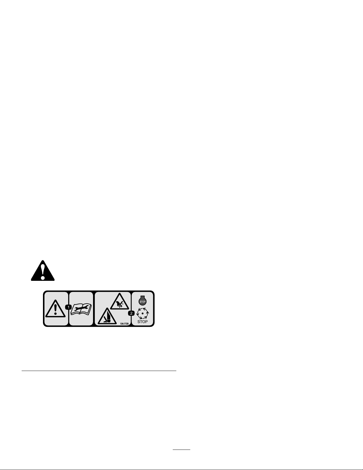
SafetyandInstructionalDecals.
Safetydecalsandinstructionsareeasilyvisibletotheoperatorandarelocatednearanyareaofpotential
danger.Replaceanydecalthatisdamagedorlost.
104–7729
1.Warning—readthe
instructionsbefore
servicingorperforming
maintenance.
2.Cutting/dismemberment
hazard;handorfoot—stop
theengineandwaitfor
movingpartstostop.
3
Page 4
Setup
g014596
1
2
2
g026076
1
2
MediaandAdditionalParts
Description
Operator'sManual
Partscatalog1
InstallingtheFrontRoller
Thecuttingunitisshippedwithoutafrontroller.Installthe
rollerusingtheloosepartssuppliedwiththecuttingunitand
installationinstructionsincludedwiththeroller.
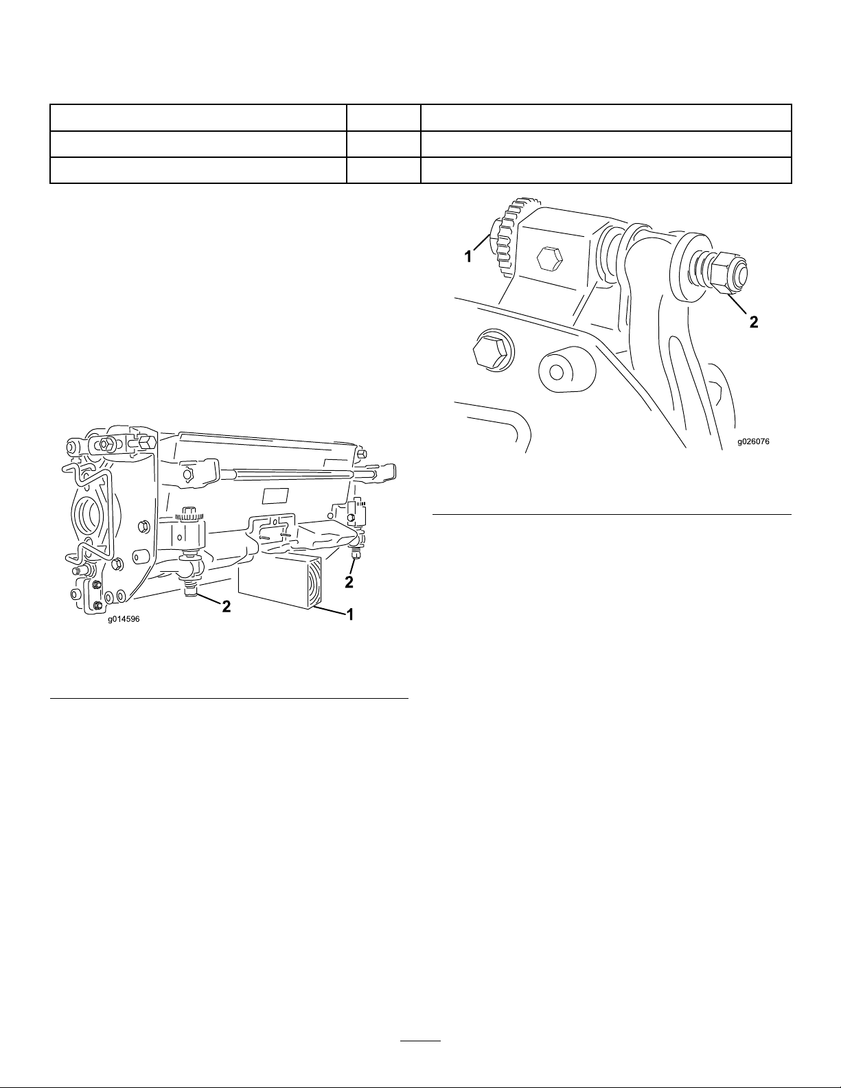
UsingtheCuttingUnitProp
Wheneverthecuttingunithastobetippedtoexposethe
bedknife/reel,propuptherearofthecuttingunittomake
surethenutsonthebackendofthebedbaradjustingscrews
arenotrestingontheworksurface(Figure3).
Qty.
Use
1
Readbeforeinstallingandoperatingcuttingunit
Usetoreferencepartnumbers
Figure4
1.Bedknifeadjustingscrew
2.Nut
Figure3
1.Prop(notprovided)2.Bedknifeadjustingscrew
nut(2)
AdjustingtheBedknifetothe
Reel
Note:Usethisprocedureaftergrinding,backlapping,or
disassembly.Itisnotintendedasadailyadjustment.
1.Positionthecuttingunitonaat,levelworksurface.
2.Tipthecuttingunittoexposethebedknifeandthe
reel.Makesurethenutsorthebackofthebedbar
adjustingscrewsarenotrestingonthework
surface(Figure4).
3.Rotatethereelsothatabladecrossesthebedknifeedge
betweentherstandsecondbedknifescrewheadson
therightsideofthecuttingunit.
4.Putanidentifyingmarkonthebladewhereit
crossesthebedknifeedge;thiswillmakesubsequent
adjustmentseasier.
5.Insertthe.05mm(0.002inch)shimbetweenthe
markedbladeandthebedknifeedgeatthepointwhere
themarkedbladecrossesthebedknifeedge.
6.Turntherightbedbaradjustingscrewuntilyoufeel
lightpressure(i.e.drag)ontheshimbyslidingit
side-to-side.Removetheshim.
7.Fortheleftsideofthecuttingunit,slowlyrotatethe
reelsothattheclosestbladecrossesthebedknifeedge
betweentherstandsecondscrewheads.
8.Repeatsteps4through6fortheleftsideofthecutting
unitandleftbedbaradjustingscrew.
9.Repeatsteps5and6untillightdragisachievedon
boththerightandleftsidesofthecuttingunitutilizing
thesamecontactpoints.
Thebedknifeisnowparalleltothereel.
10.Toobtainlightcontactbetweenthereelandbedknife,
turneachbedbaradjustingscrewclockwise3clicks.
Note:Eachclickturnedonthebedbaradjusting
screwmovesthebedknife0.018mm(0.0007inches).
Clockwiserotationmovesthebedknifeedgecloser
4
Page 5
tothereelandcounterclockwiserotationmovethe
bedknifeedgeawayfromthereel.Donotovertighten
theadjustingscrews.
11.Testthecuttingperformancebyinsertingalongstrip
ofcuttingperformancepaper(T oropartnumber
125-5610)betweenthereelandbedknife,perpendicular
tothebedknife(Figure5).Slowlyrotatethereel
forward;itshouldcutpaper
Positionthespacerbelowthesideplatemounting
angewhenheightofcutsettingsrangefrom3to25
mm(1/8to1inch)(Figure7).
Figure7
1.Spacer3.Sideplatemountingange
2.Rollerbracket
2.Toadjustrearrollerproceedasfollows:
A.Raisetherearofthecuttingunitandplaceablock
underthebedknife.
Figure5
Note:Ifexcessivecontact/reeldragisevidentitwill
beeithernecessarytobacklap,refacethefrontofthe
bedknife,orregrindthecuttingunittoachievethe
sharpedgesneededforprecisioncutting(Refertothe
ToroManualforSharpeningReelandRotaryMowers,
FormNo.09168SL).
AdjustingtheRearRoller
1.Adjusttherearrollerbrackets(Figure6orFigure7)
totheloworhighpositiondependingonthedesired
heightofcutrange.
Positionthespacerabovethesideplatemountingange
(factorysetting)whenheightofcutsettingsrangefrom
1.6to6mm(1/16to1/4inch)(Figure6).
B.Removethe2nutssecuringeachrollerbracket
andspacertoeachsideplatemountingange.
C.Lowertherollerandscrewsfromthesideplate
mountingangesandspacers.
D.Placethespacersontothescrewsontheroller
brackets.
E.Securetherollerbracketandspacerstothe
undersideofthemountingangeswiththenuts
previouslyremoved.
Note:Thepositionoftherearrollertothereel
iscontrolledbythemachiningtolerancesofthe
assembledcomponentsandparallelingisnotrequired.
AdjustingtheHeightofCut
Note:Forheightsofcutgreaterthan1.270cm(0.500inch),
youmustinstallthehighheightofcutkit.
Important:Wheneverthecuttingunithastobetipped
toexposethebedknife/reel,propuptherearofthe
cuttingunittomakesurethenutsonthebackendof
thebedbaradjustingscrewsarenotrestingonthework
surface(Figure3).
Figure6
1.Spacer3.Sideplatemountingange
2.Rollerbracket
1.Loosenthelocknutssecuringtheheight-of-cutarmsto
thecuttingunitsideplates(Figure8).
5
Page 6

G020095
1.Gaugebar
Figure10
Figure8
1.Height-of-cutarm
2.Locknut
3.Adjustingbolt
2.Loosenthenutonthegaugebarandsettheheight
adjustingbolttothedesiredheight-of-cut(Figure9).
Thedistancebetweenthebottomoftheboltheadand
thefaceofthebaristheheight-of-cut.
Figure9
1.Gaugebar
2.Heightadjustingbolt
3.Nut
3.Hooktheboltheadontothecuttingedgeofthe
bedknifeandresttherearendofthebarontotherear
oftheroller(Figure10).
4.Rotatetheadjustingboltontheheight-of-cutarms
untilthefrontrollercontactsthegaugebar.Adjust
bothendsoftherolleruntiltheentirerollerisparallel
tothebedknife.
Important:Whensetproperly,therearandfront
rollerswillcontactthegaugebarandthebolthead
willbesnugagainstthebedknife.Thisensures
thattheheight-of-cutisidenticalatbothendsof
thebedknife.
5.Tightenthenutstosecuretheadjustment.Donot
overtightenthenuts.Tightenthemenoughtoremove
playfromthewasher.
Note:Usethefollowingcharttodeterminewhich
bedknifeisbestsuitedforthedesiredheightofcut.
RecommendedBedknife/HeightofCutChart
Bedknife
Edgemax
Micro-cut
(Standard)
Edgemax
Tournament
(Optional)
Micro-cut
(Optional)
Tournament
(Optional)
Extended
Micro-cut
(Optional)
Extended
Tournament
(Optional)
Low-cut
(Optional)
High-cut
(Optional)
Fairway
(Optional)
PartNumber
115-18801.5–4.7mm
(0.062–0.188inch)
115-18813.1–12.7mm
(0.125–0.500inch)
93-42621.5–4.7mm
(0.062–0.188inch)
93-42633.1–12.7mm
(0.125–0.500inch)
108-43031.5–4.7mm
(0.062–0.188inch)
108-43023.1–12.7mm
(0.125–0.500inch)
93-42644.7–25.4mm
(0.188–1.00inch)
94-63927.9–25.4mm
(0.312–1.00inch)
63-86009.5–25.4mm
(0.375–1.00inch)
HeightofCut
6
Page 7

AdjustingtheCut-OffBar
1
g014643
Adjustthecut-offbartoensurethattheclippingsarecleanly
dischargedfromthereelarea:
1.Loosenthescrewssecuringthetopbar(Figure11)to
thecuttingunit.
Figure11
1.Cut-offbar
2.Inserta0.060inchfeelergaugebetweenthetopofthe
reelandthebarandtightenthescrews.Ensurethebar
andreelareequaldistanceapartacrossthecomplete
reelforoptimumperformance.
Note:Thebarisadjustabletocompensateforchanges
inturfconditions.Adjustthebarclosertothereel
whentheturfisextremelydry.Bycontrast,adjustthe
barfurtherawayfromthereelwhentheturfconditions
arewet.Adjustthebarwheneveryousharpenthereel
onareelgrinder.
7
Page 8

ProductOverview
Specications.
Tractors
HeightofCutCuttingheightisadjustedonthefrontrollerbytwoverticalscrewsandheldbytwolocking
HeightOfCutRangeStandardbenchheight-of-cutrangeis1.6mm(0.062inch)to12.7mm(0.500inch).Bench
ReelBearingsT wosealedstainlesssteel,deepgrooveballbearings.
Rollers
BedknifeReplaceablesingleedged,highcarbonsteelbedknifeisfastenedtoamachinedcastiron
BedknifeAdjustmentDualscrewadjustmenttothereel;detentscorrespondingto0.018mm(0.0007inch)
GrassShieldNon-adjustableshieldwithadjustablecut-offbartoimprovegrassdischargefromreelin
Counterweight
NetWeight
ThesecuttingunitswillmountontheGreensmaster3300and3400TractionUnits.
capscrews
height-of-cutrangewiththeHighHeightofCutKitinstalledis7mm(0.285inch)to25mm
(1.00inch).Effectiveheightofcutmayvarydependingonturfconditions,typeofbedknife,
rollers,andattachmentsinstalled
Therearrollerisa5.1cm(2inch)diametersteelfullroller
bedbarwith13screws.
bedknifemovementforeachindexedposition.
wetconditions.
Acastironweightmountedoppositetothedrivemotorbalancesthecuttingunit.
8Blade—32kg(71lb),11Blade—34kg(74lb),14Blade—35kg(77lb)
Attachments/Accessories
AselectionofToroapprovedattachmentsandaccessoriesis
availableforusewiththemachinetoenhanceandexpand
itscapabilities.ContactyourAuthorizedServiceDealeror
Distributororgotowww .Toro.comforalistofallapproved
attachmentsandaccessories.
8
Page 9

Operation
Note:Determinetheleftandrightsidesofthemachine
fromthenormaloperatingposition.
CuttingUnitCharacteristics
Thedualknobbedknife-to-reeladjustmentsystem
incorporatedinthiscuttingunitsimpliestheadjustment
procedureneededtodeliveroptimummowingperformance.
Thepreciseadjustmentpossiblewiththedualknob/bedbar
designgivesthenecessarycontroltoprovideacontinual
self-sharpeningaction-thusmaintainingsharpcuttingedges,
ensuringgoodquality-of-cut,andgreatlyreducingtheneed
forroutinebacklapping.
DailyAdjustmentsofthe CuttingUnit
Priortomowingeachday,orasrequired,checkeachcutting
unittoverifyproperbedknife-to-reelcontact.Thismustbe
performedeventhoughqualityofcutisacceptable.
bedknife,orregrindthecuttingunittoachievethe
sharpedgesneededforprecisioncutting(Refertothe
ToroManualforSharpeningReelandRotaryMowers,
FormNo.09168SL).
Important:Lightcontactispreferredatalltimes.If
youdonotmaintainlightcontact,thebedknifeandreel
edgeswillnotsufcientlyself-sharpenandwilldullafter
aperiodofoperation.Ifyoumaintainexcessivecontact,
thebedknifeandreelwillwearquicker,wearunevenly,
andthequalityofcutmaybeadverselyaffected.
Note:Afterextendedrunning,aridgewilleventually
developatbothendsofthebedknife.Roundofforlethese
notchesushwiththecuttingedgeofthebedknifetoensure
smoothoperation.
1.Lowerthecuttingunitsontoahardsurface,shutoff
theengine,andremovetheignitionkey.
2.Slowlyrotatethereelinareversedirection,listening
forreel-to-bedknifecontact.
Note:Theadjustmentknobshavedetents
correspondingto0.018mm(0.0007inch)bedknife
movementforeachindexedposition.Referto
AdjustingtheBedknifetotheReel.
3.Testthecuttingperformancebyinsertingalongstrip
ofcuttingperformancepaper(T oropartnumber
125-5610)betweenreelandbedknife,perpendicular
tothebedknife(Figure12).Slowlyrotatethereel
forward;itshouldcutthepaper.
Figure12
Note:Ifexcessivecontact/reeldragisevidentitwill
beeithernecessarytobacklap,refacethefrontofthe
9
Page 10

Maintenance
1
G020096
Note:Determinetheleftandrightsidesofthemachine
fromthenormaloperatingposition.
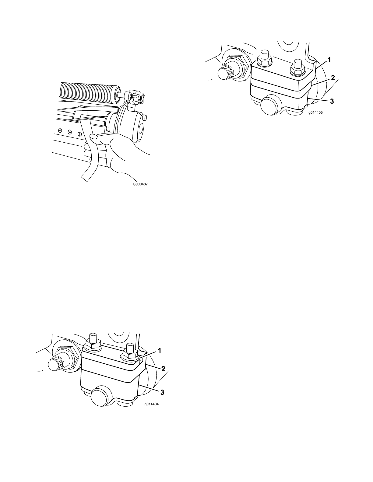
ServicingtheBedbar
RemovingtheBedbar
1.Turnthebedbaradjusterscrewcounterclockwise,to
backthebedknifeawayfromthereel(Figure13).
Figure15
Figure13
1.Bedbaradjustingscrew3.Bedbar
2.Springtensionnut
2.Backoutthespringtensionnut,untilthewasherisno
longertensionedagainstthebedbar(Figure13).
3.Oneachsideofthemachine,loosenthelocknut
securingthebedbarbolt(Figure14).
4.Washer
Figure14
1.Bedbarbolt
2.Locknut4.Nylonwasher
3.Steelwasher
AssemblingtheBedbar
1.Installthebedbar,positioningthemountingears
betweenthewasherandbedbaradjuster.
2.Securethebedbartoeachsideplatewith2bedbar
bolts,locknuts(nutsonbolts),and6washers.Position
anylonwasheroneachsideofthesideplateboss.
Placeasteelwasheroutsideoftheouternylonwasher
(Figure15).
3.Torquethebedbarboltsto27-36N-m(240-320
inch-lb).
4.Tightenthelocknutsequallyoneachsideuntilyou
cannotrotatethesteelwashersbyhand().
5.Loosenthelocknutsjustuntilyoucanrotatethesteel
washersbyhandandyetthereisnoendplayinthe
bedbar.
Important:Ifyouovertightenthelocknuts,you
maydeectthesideplateswhichcouldinterfere
withthebedknifetoreelcontact.
1.Bedbarbolt2.Locknut
4.Removeeachbedbarboltallowingthebedbartobe
pulleddownwardandremovedfromthemachine
bolt(Figure14).Accountforthetwonylonandone
stampedsteelwashersoneachendofthebedbar
(Figure15).
Note:Thewashersontheinsidemayhaveagap.
6.Tightenthespringtensionnutuntilthespringis
collapsed,thenbackitoff1/2turn(Figure16).
10
Page 11

g014642
1
2
Figure16
1.Springtensionnut2.Spring
7.Adjustthebedknifetothereel;refertoAdjustingthe
BedknifetotheReel.
BacklappingtheReel
DANGER
Contactwiththereelorothermovingpartscan
resultinpersonalinjury.
Keepngers,hands,andclothingawayfromthe
reelsorothermovingparts.
•Stayawayfromthereelwhilebacklapping.
•Neveruseashorthandledpaintbrushfor
backlapping.PartNo.29-9100Handleassembly
completeorindividualpartsareavailablefrom
yourlocalAuthorizedT oroDistributor.
1.Positionthemachineonaclean,levelsurface,lower
thecuttingunits,stoptheengine,engagetheparking
brake,andremovetheignitionkey.
2.Removethereelmotorsfromthecuttingunitsand
disconnectandremovethecuttingunitsfromthelift
arms.
3.Connectthebacklappingmachinetothecuttingunit
byinsertingapieceof3/8inchsquarestockintothe
splinedcouplingintheendofthecuttingunit.
Note:Additionalinstructionsandprocedureson
BacklappingareavailableintheToroSharpeningReeland
RotaryMowersManual,FormNumber80-300PT.
Note:Forabettercuttingedge,runaleacrossthe
frontfaceofthebedknifeandreelwhenthelapping
operationiscompleted.Thiswillremoveanyburrsor
roughedgesthatmayhavebuiltuponthecuttingedge.
11
Page 12

Notes:
12
Page 13

Notes:
13
Page 14

Notes:
14
Page 15

DeclarationofIncorporation
TheT oroCompany,81 11LyndaleAve.South,Bloomington,MN,USAdeclaresthatthefollowingunit(s)
conform(s)tothedirectiveslisted,wheninstalledinaccordancewiththeaccompanyinginstructionsontocertain
ToromodelsasindicatedontherelevantDeclarationsofConformity.
ModelNo.
04613313000001andUp8-BladeDPAReelMower8BLADEDPA-TRIFLEX8-BladeDPAReelMower
04614313000001andUp11-BladeDP AReelMower11BLADEDPA-TRIFLEX11-BladeDP AReelMower
04615313000001andUp14-BladeDP AReelMower14BLADEDPA-TRIFLEX14-BladeDP AReelMower
SerialNo.
ProductDescriptionInvoiceDescription
GeneralDescription
Directive
2006/42/EC,
2000/14/EC
2006/42/EC,
2000/14/EC
2006/42/EC,
2000/14/EC
RelevanttechnicaldocumentationhasbeencompiledasrequiredperPartBofAnnexVIIof2006/42/EC.
Wewillundertaketotransmit,inresponsetorequestsbynationalauthorities,relevantinformationonthispartly
completedmachinery.Themethodoftransmissionshallbeelectronictransmittal.
ThismachineryshallnotbeputintoserviceuntilincorporatedintoapprovedToromodelsasindicatedonthe
associatedDeclarationofConformityandinaccordancewithallinstructions,wherebyitcanbedeclaredin
conformitywithallrelevantDirectives.
Certied:EUTechnicalContact:
PeterT etteroo
ToroEuropeNV
B-2260Oevel-Westerloo
Belgium
DavidKlisTel.003214562960
Sr.EngineeringManager
811 1LyndaleAve.South
Bloomington,MN55420,USA
September26,2013
Fax003214581911
15
Page 16

TheToroTotalCoverageGuarantee
ALimitedWarranty
ConditionsandProductsCovered
TheToroCompanyanditsafliate,T oroWarrantyCompany,pursuant
toanagreementbetweenthem,jointlywarrantyourT oroCommercial
product(“Product”)tobefreefromdefectsinmaterialsorworkmanship
fortwoyearsor1500operationalhours*,whicheveroccursrst.This
warrantyisapplicabletoallproductswiththeexceptionofAerators
(refertoseparatewarrantystatementsfortheseproducts).Wherea
warrantableconditionexists,wewillrepairtheProductatnocosttoyou
includingdiagnostics,labor,parts,andtransportation.Thiswarranty
beginsonthedatetheProductisdeliveredtotheoriginalretailpurchaser.
*Productequippedwithanhourmeter.
InstructionsforObtainingWarrantyService
YouareresponsiblefornotifyingtheCommercialProductsDistributoror
AuthorizedCommercialProductsDealerfromwhomyoupurchasedthe
Productassoonasyoubelieveawarrantableconditionexists.Ifyouneed
helplocatingaCommercialProductsDistributororAuthorizedDealer,or
ifyouhavequestionsregardingyourwarrantyrightsorresponsibilities,
youmaycontactusat:
ToroCommercialProductsServiceDepartment
ToroWarrantyCompany
811 1LyndaleAvenueSouth
Bloomington,MN55420-1196
952–888–8801or800–952–2740
E-mail:commercial.warranty@toro.com
OwnerResponsibilities
AstheProductowner,youareresponsibleforrequiredmaintenanceand
adjustmentsstatedinyourOperator'sManual.Failuretoperformrequired
maintenanceandadjustmentscanbegroundsfordisallowingawarranty
claim.
ItemsandConditionsNotCovered
Notallproductfailuresormalfunctionsthatoccurduringthewarranty
periodaredefectsinmaterialsorworkmanship.Thiswarrantydoesnot
coverthefollowing:
•Productfailureswhichresultfromtheuseofnon-T ororeplacement
parts,orfrominstallationanduseofadd-on,ormodiednon-Toro
brandedaccessoriesandproducts.Aseparatewarrantymaybe
providedbythemanufactureroftheseitems.
•Productfailureswhichresultfromfailuretoperformrecommended
maintenanceand/oradjustments.Failuretoproperlymaintainyour
ToroproductpertheRecommendedMaintenancelistedinthe
Operator’sManualcanresultinclaimsforwarrantybeingdenied.
•ProductfailureswhichresultfromoperatingtheProductinanabusive,
negligent,orrecklessmanner.
•Partssubjecttoconsumptionthroughuseunlessfoundtobedefective.
Examplesofpartswhichareconsumed,orusedup,duringnormal
Productoperationinclude,butarenotlimitedto,brakepadsand
linings,clutchlinings,blades,reels,rollersandbearings(sealedor
greasable),bedknives,sparkplugs,castorwheelsandbearings,tires,
lters,belts,andcertainsprayercomponentssuchasdiaphragms,
nozzles,andcheckvalves,etc.
•Failurescausedbyoutsideinuence.Conditionsconsideredtobe
outsideinuenceinclude,butarenotlimitedto,weather,storage
practices,contamination,useofunapprovedfuels,coolants,lubricants,
additives,fertilizers,water,orchemicals,etc.
•Failureorperformanceissuesduetotheuseoffuels(e.g.gasoline,
diesel,orbiodiesel)thatdonotconformtotheirrespectiveindustry
standards.
•Normalnoise,vibration,wearandtear ,anddeterioration.
•Normal“wearandtear”includes,butisnotlimitedto,damagetoseats
duetowearorabrasion,wornpaintedsurfaces,scratcheddecalsor
windows,etc.
Parts
Partsscheduledforreplacementasrequiredmaintenancearewarranted
fortheperiodoftimeuptothescheduledreplacementtimeforthatpart.
Partsreplacedunderthiswarrantyarecoveredforthedurationofthe
originalproductwarrantyandbecomethepropertyofT oro.T orowillmake
thenaldecisionwhethertorepairanyexistingpartorassemblyorreplace
it.T oromayuseremanufacturedpartsforwarrantyrepairs.
DeepCycleandLithium-IonBatteryWarranty:
DeepcycleandLithium-Ionbatterieshaveaspeciedtotalnumberof
kilowatt-hourstheycandeliverduringtheirlifetime.Operating,recharging,
andmaintenancetechniquescanextendorreducetotalbatterylife.Asthe
batteriesinthisproductareconsumed,theamountofusefulworkbetween
chargingintervalswillslowlydecreaseuntilthebatteryiscompletelyworn
out.Replacementofwornoutbatteries,duetonormalconsumption,
istheresponsibilityoftheproductowner.Batteryreplacementmaybe
requiredduringthenormalproductwarrantyperiodatowner’sexpense.
Note:(Lithium-Ionbatteryonly):ALithium-Ionbatteryhasapartonly
proratedwarrantybeginningyear3throughyear5basedonthetime
inserviceandkilowatthoursused.RefertotheOperator'sManualfor
additionalinformation.
MaintenanceisatOwner’sExpense
Enginetune-up,lubrication,cleaningandpolishing,replacementoflters,
coolant,andcompletingrecommendedmaintenancearesomeofthe
normalservicesT oroproductsrequirethatareattheowner’sexpense.
GeneralConditions
RepairbyanAuthorizedToroDistributororDealerisyoursoleremedy
underthiswarranty.
NeitherTheToroCompanynorToroWarrantyCompanyisliablefor
indirect,incidentalorconsequentialdamagesinconnectionwiththe
useoftheToroProductscoveredbythiswarranty,includingany
costorexpenseofprovidingsubstituteequipmentorserviceduring
reasonableperiodsofmalfunctionornon-usependingcompletion
ofrepairsunderthiswarranty.ExceptfortheEmissionswarranty
referencedbelow,ifapplicable,thereisnootherexpresswarranty.All
impliedwarrantiesofmerchantabilityandtnessforusearelimitedto
thedurationofthisexpresswarranty.
Somestatesdonotallowexclusionsofincidentalorconsequential
damages,orlimitationsonhowlonganimpliedwarrantylasts,sotheabove
exclusionsandlimitationsmaynotapplytoyou.Thiswarrantygivesyou
speciclegalrights,andyoumayalsohaveotherrightswhichvaryfrom
statetostate.
Noteregardingenginewarranty:
TheEmissionsControlSystemonyourProductmaybecoveredby
aseparatewarrantymeetingrequirementsestablishedbytheU.S.
EnvironmentalProtectionAgency(EP A)and/ortheCaliforniaAirResources
Board(CARB).Thehourlimitationssetforthabovedonotapplytothe
EmissionsControlSystemWarranty.RefertotheEngineEmissionControl
WarrantyStatementsuppliedwithyourproductorcontainedintheengine
manufacturer’sdocumentationfordetails
CountriesOtherthantheUnitedStatesorCanada
CustomerswhohavepurchasedT oroproductsexportedfromtheUnitedStatesorCanadashouldcontacttheirT oroDistributor(Dealer)toobtain
guaranteepoliciesforyourcountry ,province,orstate.IfforanyreasonyouaredissatisedwithyourDistributor'sserviceorhavedifcultyobtaining
guaranteeinformation,contacttheT oroimporter.
374-0253RevB
 Loading...