

Page 1
FormNo.3393-398RevB
g014597
Greensmaster
®
3420TriFlex
TractionUnit
ModelNo.04540—SerialNo.315000001andUp
™
Registeratwww.T oro.com.
OriginalInstructions(EN)
*3393-398*B
Page 2
ThisproductcomplieswithallrelevantEuropeandirectives;
g014685
1
fordetails,pleaseseetheseparateproductspecicDeclaration
ofConformity(DOC)sheet.
WARNING
CALIFORNIA
Proposition65Warning
Thisproductcontainsachemicalorchemicals
knowntotheStateofCaliforniatocausecancer,
birthdefects,orreproductiveharm.
Dieselengineexhaustandsomeofits
constituentsareknowntotheStateof
Californiatocausecancer,birthdefects,
andotherreproductiveharm.
Important:Thisengineisnotequippedwithaspark
arrestermufer.ItisaviolationofCaliforniaPublic
ResourceCodeSection4442touseoroperatetheengine
onanyforest-covered,brush-covered,orgrass-covered
land.Otherstatesorfederalareasmayhavesimilarlaws.
Figure1
1.Modelandserialnumberlocation
ModelNo.
SerialNo.
Introduction
Thismachineisaride-on,reel-bladelawnmowerintended
tobeusedbyprofessional,hiredoperatorsincommercial
applications.Itisprimarilydesignedforcuttinggrasson
well-maintainedlawnsinparks,golfcourses,sportselds,
andoncommercialgrounds.Itisnotdesignedforcutting
brush,mowinggrassandothergrowthalongsidehighways,
orforagriculturaluses.
Readthisinformationcarefullytolearnhowtooperateand
maintainyourproductproperlyandtoavoidinjuryand
productdamage.Youareresponsibleforoperatingthe
productproperlyandsafely.
YoumaycontactTorodirectlyatwww .Toro.comforproduct
andaccessoryinformation,helpndingadealer,ortoregister
yourproduct.
Wheneveryouneedservice,genuineT oroparts,oradditional
information,contactanAuthorizedServiceDealerorToro
CustomerServiceandhavethemodelandserialnumbersof
yourproductready.Figure1identiesthelocationofthe
modelandserialnumbersontheproduct.Writethenumbers
inthespaceprovided.
Thismanualidentiespotentialhazardsandhassafety
messagesidentiedbythesafetyalertsymbol(Figure2),
whichsignalsahazardthatmaycauseseriousinjuryordeath
ifyoudonotfollowtherecommendedprecautions.
Figure2
1.Safetyalertsymbol
Thismanualuses2wordstohighlightinformation.
Importantcallsattentiontospecialmechanicalinformation
andNoteemphasizesgeneralinformationworthyofspecial
attention.
©2015—TheToro®Company
8111LyndaleAvenueSouth
Bloomington,MN55420
Contactusatwww.Toro.com.
2
PrintedintheUSA
AllRightsReserved
Page 3

Contents
Safety...........................................................................4
SafeOperatingPractices...........................................4
ToroMowerSafety..................................................6
SoundPowerLevel..................................................7
SoundPressureLevel...............................................7
VibrationLevel......................................................7
SafetyandInstructionalDecals.................................8
Setup...........................................................................12
1InstallingtheRollBar...........................................13
2InstallingtheSeat.................................................13
3InstallingtheSteeringWheel..................................13
4ActivatingandChargingtheBattery........................13
5InstallingtheGrass-BasketHooks..........................15
6InstallingtheCuttingUnits...................................15
7AddingRearWeight.............................................17
8InstallingEUDecals.............................................17
ProductOverview.........................................................18
Controls...............................................................18
Specications........................................................24
Attachments/Accessories........................................24
Operation....................................................................25
ThinkSafetyFirst...................................................25
CheckingtheEngineOil..........................................25
FillingtheFuelTank...............................................26
CheckingtheCoolingSystem...................................27
CheckingtheHydraulic-FluidLevel..........................27
DrainingWaterfromtheFuelFilter...........................29
CheckingtheTirePressure......................................29
CheckingtheTorqueoftheWheelNuts.....................29
CheckingtheReel-to-BedknifeContact.....................29
Breaking-intheMachine..........................................29
StartingandStoppingtheMachine............................30
InstallingandRemovingtheCuttingUnits.................30
Mowing................................................................32
DrivingtheMachinewithoutMowing.......................33
TransportingtheMachine........................................33
LoadingtheMachine..............................................34
InspectingandCleaningtheMachineafter
Mowing.............................................................34
TowingtheMachine...............................................34
Maintenance.................................................................36
RecommendedMaintenanceSchedule(s)......................36
DailyMaintenanceChecklist....................................37
Lubrication...............................................................38
GreasingtheGeneratorBeltTensioner......................38
EngineMaintenance..................................................38
ServicingtheAirCleaner.........................................38
ChangingtheEngineOilandFilter...........................39
FuelSystemMaintenance...........................................40
ServicingtheFuelFilter/WaterSeparator...................40
InspectingtheFuelLinesandConnections.................40
ElectricalSystemMaintenance....................................41
ServicingtheBattery...............................................41
StoringtheBattery..................................................41
LocatingtheFuses..................................................42
JumpStartingtheMachine.......................................42
DriveSystemMaintenance.........................................43
AdjustingtheTransmissionforNeutral.....................43
AdjustingtheTransportSpeed.................................43
AdjustingtheMowingSpeed....................................44
CoolingSystemMaintenance......................................44
CleaningtheRadiatorScreen....................................44
BrakeMaintenance....................................................45
AdjustingtheBrakes...............................................45
BeltMaintenance......................................................45
AdjustingtheAlternatorBelt...................................45
HydraulicSystemMaintenance....................................46
ChangingtheHydraulicOilandFilter........................46
CheckingtheHydraulicLinesandHoses....................46
CuttingUnitMaintenance...........................................47
BacklappingtheReels.............................................47
Storage........................................................................48
3
Page 4

Safety
Thismachinehasbeendesignedinaccordancewith
ENISO5395:2013andANSIB71.4-2012specications
ineffectatthetimeofproductionwhen16.8kg(37lb)
ofweightisaddedtotherearwheel.
Improperuseormaintenancebytheoperatororowner
canresultininjury.Toreducethepotentialforinjury,
complywiththesesafetyinstructionsandalwayspay
attentiontothesafetyalertsymbol(Figure2),which
meansCaution,Warning,orDanger—personalsafety
instruction.Failuretocomplywiththeinstructionmay
resultinpersonalinjuryordeath.
SafeOperatingPractices
Training
•ReadtheOperator’sManualandothertrainingmaterial
carefully.Befamiliarwiththecontrols,safetysigns,and
theproperuseoftheequipment.
•Iftheoperatorormechaniccannotreadthelanguage
ofthismanual,itistheowner’sresponsibilitytoexplain
thismaterialtothem.
•Neverallowchildrenorpeopleunfamiliarwiththese
instructionstouseorservicethemower.Local
regulationsmayrestricttheageoftheoperator.
•Nevermowwhilepeople,especiallychildren,orpetsare
nearby.
•Keepinmindthattheoperatororuserisresponsiblefor
accidentsorhazardsoccurringtootherpeopleortheir
property.
•Donotcarrypassengers.
•Alldriversandmechanicsshouldseekandobtain
professionalandpracticalinstruction.Theowneris
responsiblefortrainingtheusers.Suchinstructionshould
emphasize:
–theneedforcareandconcentrationwhenworking
withride-onmachines;
–controlofaride-onmachineslidingonaslopewill
notberegainedbytheapplicationofthebrake.The
mainreasonsforlossofcontrolare:
◊insufcientwheelgrip;
◊beingdriventoofast;
◊inadequatebraking;
◊thetypeofmachineisunsuitableforthetask;
◊lackofawarenessoftheeffectofground
conditions,especiallyslopes.
◊Theowner/usercanpreventandisresponsible
foraccidentsorinjuriesoccurringtopeople,or
property.
Preparation
•Whilemowing,alwayswearsubstantial,slip-resistant
footwear,longtrousers,safetyglasses,andhearing
protection.Longhair,looseclothing,orjewelrymayget
tangledinmovingparts.Donotoperatetheequipment
whenbarefootorwearingopensandals.
•Thoroughlyinspecttheareawheretheequipmentisto
beusedandremoveallobjectswhichmaybethrownby
themachine.
•Replacefaultysilencers/mufers.
•Evaluatetheterraintodeterminewhataccessoriesand
attachmentsareneededtoproperlyandsafelyperform
thejob.Onlyuseaccessoriesandattachmentsapproved
bythemanufacturer.
•Checkthatoperator’spresencecontrols,safetyswitches
andshieldsareattachedandfunctioningproperly.Donot
operateunlesstheyarefunctioningproperly.
Operation
•Donotoperatetheengineinaconnedspacewhere
dangerouscarbonmonoxideandotherexhaustgasses
cancollect.
•Mowonlyindaylightoringoodarticiallight.
•Beforeattemptingtostarttheengine,disengageallblade
attachmentclutches,shiftintoneutral,andengagethe
parkingbrake.
•Rememberthereisnosuchthingasasafeslope.Travel
ongrassslopesrequiresparticularcare.T oguardagainst
overturning:
–donotstoporstartsuddenlywhengoingupor
downhill;
–machinespeedsshouldbekeptlowonslopesand
duringtightturns;
–stayalertforhumpsandhollowsandotherhidden
hazards;
–nevermowacrossthefaceoftheslope,unlessthe
mowerisdesignedforthispurpose.
•Stayalertforholesintheterrainandotherhiddenhazards.
•Watchoutfortrafcwhencrossingornearroadways.
•Stopthebladesfromrotatingbeforecrossingsurfaces
otherthangrass.
•Whenusinganyattachments,neverdirectdischargeof
materialtowardbystandersnorallowanyonenearthe
machinewhileinoperation.
•Neveroperatethemachinewithdamagedguards,shields,
orwithoutsafetyprotectivedevicesinplace.Besureall
interlocksareattached,adjustedproperly ,andfunctioning
properly.
•Donotchangetheenginegovernorsettingsoroverspeed
theengine.Operatingtheengineatexcessivespeedmay
increasethehazardofpersonalinjury.
•Beforeleavingtheoperator’ sposition:
–stoponlevelground;
4
Page 5

–disengagethepowertake-offandlowerthe
attachments;
–changeintoneutralandsettheparkingbrake;
–stoptheengineandremovethekey.
•Disengagedrivetoattachmentswhentransportingornot
inuse.
•Stoptheengineanddisengagedrivetoattachment:
–beforerefuelling;
–beforeremovingthegrasscatcher/catchers;
–beforemakingheightadjustmentunlessadjustment
canbemadefromtheoperator’sposition.
–beforeclearingblockages;
–beforechecking,cleaningorworkingonthemower;
–afterstrikingaforeignobjectorifanabnormal
vibrationoccurs.Inspectthemowerfordamage
andmakerepairsbeforerestartingandoperatingthe
equipment.
•Reducethethrottlesettingbeforestoppingtheengine
and,iftheengineisprovidedwithafuelshut-offvalve,
turnthefueloffattheconclusionofmowing.
•Keephandsandfeetawayfromthecuttingunits.
•Lookbehindanddownbeforebackinguptobesureof
aclearpath.
•Slowdownandusecautionwhenmakingturnsand
crossingroadsandsidewalks.Stopthereelswhennot
mowing.
•Donotoperatethemowerundertheinuenceofalcohol
ordrugs.
•Lightningcancausesevereinjuryordeath.Iflightning
isseenorthunderisheardinthearea,donotoperate
themachine;seekshelter.
•Usecarewhenloadingorunloadingthemachineintoa
trailerortruck.
•Usecarewhenapproachingblindcorners,shrubs,trees,
orotherobjectsthatmayobscurevision.
RolloverProtectionSystem(ROPS)UseandMaintenance
•TheROPSisanintegralandeffectivesafetydevice.Keep
afoldingROPSintheraisedandlockedpositionanduse
theseatbeltwhenoperatingthemachine.
•LowerafoldingROPStemporarilyonlywhenabsolutely
necessary.Donotweartheseatbeltwhenfoldeddown.
•Beawarethereisnorolloverprotectionwhenafolded
ROPSisinthedownposition.
•Becertainthattheseatbeltcanbereleasedquicklyin
theeventofanemergency.
•Checktheareatobemowedandneverfolddowna
foldingROPSinareaswherethereareslopes,dropoffs
orwater.
•Checkcarefullyforoverheadclearances(i.e.branches,
doorways,electricalwires)beforedrivingunderany
objectsanddonotcontactthem.
•KeeptheROPSinsafeoperatingconditionby
periodicallythoroughlyinspectingfordamageand
keepingallmountingfastenerstight.
•ReplaceadamagedROPS.Donotrepairorrevise.
•DonotremovetheROPS.
•AnyalterationstoaROPSmustbeapprovedbythe
manufacturer.
SafeHandlingofFuels
•Toavoidpersonalinjuryorpropertydamage,use
extremecareinhandlinggasoline.Gasolineisextremely
ammableandthevaporsareexplosive.
•Extinguishallcigarettes,cigars,pipes,andothersources
ofignition.
•Useonlyanapprovedfuelcontainer.
•Neverremovefuelcaporaddfuelwiththeengine
running.
•Allowenginetocoolbeforerefueling.
•Neverrefuelthemachineindoors.
•Neverstorethemachineorfuelcontainerwherethereis
anopename,spark,orpilotlightsuchasonawater
heateroronotherappliances.
•Neverllcontainersinsideavehicleoronatruckor
trailerbedwithaplasticliner.Alwaysplacecontainerson
thegroundawayfromyourvehiclebeforelling.
•Removeequipmentfromthetruckortrailerandrefuelit
ontheground.Ifthisisnotpossible,thenrefuelsuch
equipmentwithaportablecontainer,ratherthanfroma
fueldispensernozzle.
•Keepthenozzleincontactwiththerimofthefueltank
orcontaineropeningatalltimesuntilfuelingiscomplete.
•Donotuseanozzlelockopendevice.
•Iffuelisspilledonclothing,changeclothingimmediately.
•Neveroverllfueltank.Replacefuelcapandtighten
securely.
MaintenanceandStorage
•Keepallnuts,boltsandscrewstighttobesurethe
equipmentisinsafeworkingcondition.
•Neverstoretheequipmentwithfuelinthetankinsidea
buildingwherefumesmayreachanopenameorspark.
•Allowtheenginetocoolbeforestoringinanyenclosure.
•Toreducetheriskofrehazard,keeptheengine,
silencer/mufer,batterycompartment,andfuelstorage
areafreeofgrass,leaves,orexcessivegrease.
•Replacewornordamagedpartsforsafety.
5
Page 6

•Checkthegrasscatcherfrequentlyforwearor
deterioration.
•Keepallpartsingoodworkingconditionandallhardware
andhydraulicttingstightened.Replaceallwornor
damagedpartsanddecals.
•Ifthefueltankhastobedrained,dothisoutdoors.
•Becarefulduringadjustmentofthemachinetoprevent
entrapmentofthengersbetweenmovingbladesand
xedpartsofthemachine.
•Onmulti-reelmachines,takecareasrotatingonereelcan
causeotherreelstorotate.
•Disengagedrives,lowerthecuttingunits,setparking
brake,stopengineandremovekey .Waitforallmovement
tostopbeforeadjusting,cleaningorrepairing.
•Cleangrassanddebrisfromcuttingunits,drives,mufers,
andenginetohelppreventres.Cleanupoilorfuel
spillage.
•Usejackstandstosupportcomponentswhenrequired.
•Carefullyreleasepressurefromcomponentswithstored
energy.
•Disconnectbatterybeforemakinganyrepairs.Disconnect
thenegativeterminalrstandthepositivelast.Reconnect
positiverstandnegativelast.
•Usecarewhencheckingthereels.Wrapthereelsorwear
gloves,andusecautionwhenservicingthem.
•Keephandsandfeetawayfrommovingparts.Ifpossible,
donotmakeadjustmentswiththeenginerunning.
•Chargebatteriesinanopenwellventilatedarea,away
fromsparkandames.Unplugchargerbeforeconnecting
ordisconnectingfrombattery.W earprotectiveclothing
anduseinsulatedtools.
Operation
•Knowhowtostoptheenginequickly.
•Alwayswearsubstantial,slip-resistantshoes.Donot
operatethemachinewhilewearingsandals,tennisshoes,
orsneakers.Wearingsafetyshoesandlongpantsis
advisableandrequiredbysomelocalordinancesand
insuranceregulations.
•Theoperatormustbeskilledandtrainedinhowtodrive
onhillsides.Failuretousecautiononslopesorhillsmay
causelossofcontrolandcausethevehicletotiporroll,
possiblyresultinginpersonalinjuryordeath.
•Handlefuelcarefully.Wipeupanyspills.
•Checkthesafetyinterlockswitchesdailyforproper
operation.Ifaswitchhasfailed,replacetheswitchbefore
operatingthemachine
•Beforeattemptingtostarttheengine,sitontheseat,pull
theliftleverbackandreleaseittoensurethecutting
unitsaredisengaged.V erifythatthetractionsystemisin
neutralandtheparkingbrakeisset.
•Usingthemachinedemandsattention.Topreventloss
ofcontrol:
–Donotdriveclosetosandtraps,ditches,creeks,or
otherhazards.
–Reducespeedwhenmakingsharpturns.Avoid
suddenstopsandstarts.
–Watchoutfortrafcwhennearorcrossingroads.
Alwaysyieldtheright-of-way.
–Applytheservicebrakeswhengoingdownhillto
keepforwardspeedslowandtomaintaincontrolof
themachine.
•Shuttheengineoffbeforeemptyingthebaskets.
Hauling
•Usecarewhenloadingorunloadingthemachineintoa
trailerortruck.
•Usefullwidthrampsforloadingmachineintotraileror
truck.
•Tiethemachinedownsecurelyusingstraps,chains,cable,
orropes.Bothfrontandrearstrapsshouldbedirected
downandoutwardfromthemachine.
ToroMowerSafety
ThefollowinglistcontainssafetyinformationspecictoToro
productsorothersafetyinformationthatyoumustknowthat
isnotincludedintheANSIstandards.
Thisproductiscapableofamputatinghandsandfeetand
throwingobjects.Alwaysfollowallsafetyinstructionsto
avoidseriousinjuryordeath.
Useofthisproductforpurposesotherthanitsintendeduse
couldprovedangeroustouserandbystanders.
•Raisethecuttingunitswhendrivingfromoneworkarea
toanother.
•Donottouchtheengine,mufer,orexhaustpipewhile
theengineisrunningorsoonafterithasstoppedbecause
theseareascouldbehotenoughtocauseburns.
•Beforegettingoffoftheseat,movethefunctionalcontrol
levertoneutral(N),raisethecuttingunitsandwaitfor
thereelstostopspinning.Settheparkingbrake.Stopthe
engineandremovethekeyfromtheignitionswitch.
•Traverseslopescarefully.Donotstartorstopsuddenly
whentravelinguphillordownhill.
•Theoperatormustbeskilledandtrainedinhowtodrive
onhillsides.Failuretousecautiononslopesorhillsmay
causelossofcontrolandcausethemachinetotiporroll,
possiblyresultinginpersonalinjuryordeath.
•Iftheenginestallsorlosesheadwayandcannotmakeit
tothetopofaslope,donotturnthemachinearound.
Alwaysbackslowly,straightdowntheslope.
•Whenapersonorpetappearsunexpectedlyinornear
themowingarea,stopmowing.Carelessoperation,
6
Page 7

combinedwithterrainangles,ricochets,orimproperly
positionedguardscanleadtothrownobjectinjuries.Do
notresumemowinguntiltheareaiscleared.
•AlwaysusetheseatbeltwiththeROPSwhenoperating
themachine.
•Wheneverthemachineisleftunattended,makesurethe
cuttingunitsarefullyraised,thereelsarenotspinning,
thekeyisremovedfromtheignitionswitch,andthe
parkingbrakeisset.
MaintenanceandStorage
•Makesureallhydrauliclineconnectorsaretightandall
hydraulichosesandlinesareingoodconditionbefore
applyingpressuretothesystem.
SoundPowerLevel
Thisunithasaguaranteedsoundpowerlevelof98dBA,
whichincludesanUncertaintyValue(K)of1dBA.
Soundpowerlevelwasdeterminedaccordingtothe
proceduresoutlinedinISO11094.
SoundPressureLevel
Thisunithasasoundpressurelevelattheoperator’searof84
dBA,whichincludesanUncertaintyValue(K)of1dBA.
Soundpressurelevelwasdeterminedaccordingtothe
proceduresoutlinedinENISO5395:2013.
•Keepyourbodyandhandsawayfrompinholeleaksor
nozzlesthatejecthydraulicuidunderhighpressure.
Usepaperorcardboard,notyourhands,tosearchfor
leaks.Hydraulicuidescapingunderpressurecanhave
sufcientforcetopenetratetheskinandcauseserious
injury.
•Beforedisconnectingorperforminganyworkonthe
hydraulicsystem,allpressureinthesystemmustbe
relievedbystoppingtheengineandloweringthecutting
unitsandattachmentstotheground.
•Checkallfuellinesfortightnessandwearonaregular
basis.Tightenorrepairthemasneeded.
•Iftheenginemustberunningtoperformamaintenance
adjustment,keephands,feet,clothing,andanypartsof
thebodyawayfromthecuttingunits,attachments,and
anymovingparts,especiallythescreenatthesideofthe
engine.Keepeveryoneaway.
•Toensuresafetyandaccuracy,haveanAuthorizedToro
Distributorcheckthemaximumenginespeedwitha
tachometer.Maximumgovernedenginespeedshould
be2900rpm.
•Theenginemustbeshutoffbeforecheckingtheoilor
addingoiltothecrankcase.
VibrationLevel
Hand-Arm
Measuredvibrationlevelforrighthand=0.33m/s
Measuredvibrationlevelforlefthand=0.52m/s
UncertaintyValue(K)=0.26m/s
Measuredvaluesweredeterminedaccordingtotheprocedures
outlinedinENISO5395:2013.
WholeBody
Measuredvibrationlevel=0.12m/s
UncertaintyValue(K)=0.06m/s
Measuredvaluesweredeterminedaccordingtotheprocedures
outlinedinENISO5395:2013.
2
2
2
2
2
•Ifmajorrepairsareeverneededorifassistanceisdesired,
contactanAuthorizedToroDistributor.
•Toensureoptimumperformanceandcontinuedsafety
certicationofthemachine,useonlygenuineToro
replacementpartsandaccessories.Replacementparts
andaccessoriesmadebyothermanufacturerscouldbe
dangerous,andsuchusecouldvoidtheproductwarranty.
•Disconnectthecuttingunitsfromthepowersupply ,
usingthecuttingunitpowerdisconnectcouplers,before
performinganyworkonthecuttingunits.
7
Page 8

SafetyandInstructionalDecals
Safetydecalsandinstructionsareeasilyvisibletotheoperatorandarelocatednearanyareaofpotential
danger.Replaceanydecalthatisdamagedorlost.
119-9343
115-8156
1.Reelheight3.8Bladecuttingunit5.14Bladecuttingunit7.Fast
2.5Bladecuttingunit4.11Bladecuttingunit6.Reelspeed
8.Slow
8
Page 9
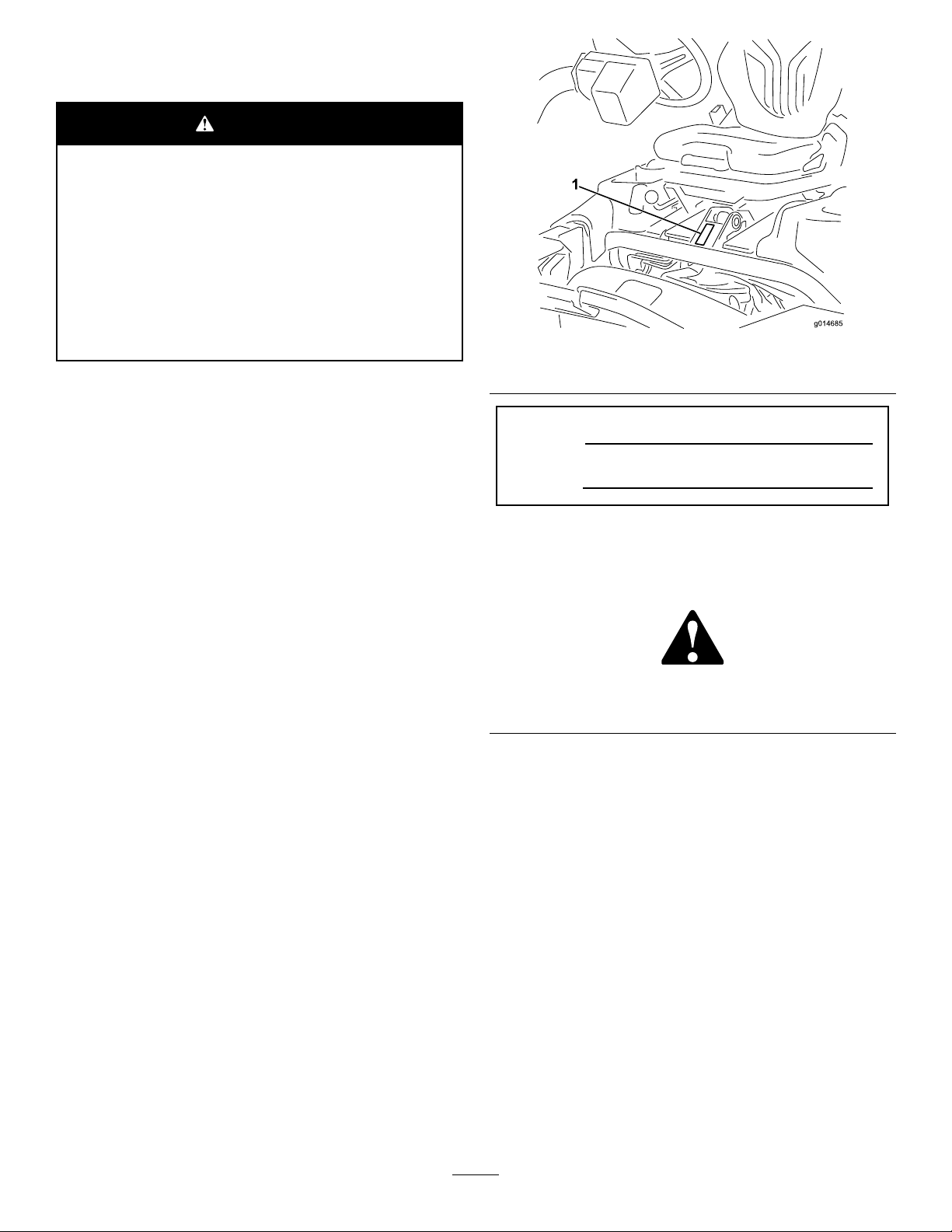
115-8155
1.Warning—readtheOperator'sManual,donotprimeoruse
startinguid.
115-8203
121–6670
1.Engagethereels.2.Disengagethereels.
117–2718
1.ReadtheOperator's
manualforfuse
information.
2.Radiatorfan—50Amp
121–5169
1.Throttle—slow5.Functionalcontrollever
2.Throttle—continuousvariablesetting6.Lowerthereelsandengage.
3.Throttle—fast7.Useforbacklappingreels
4.Raisethereels8.Neutral
9.Useformowing
10.Usefortransport
9
Page 10
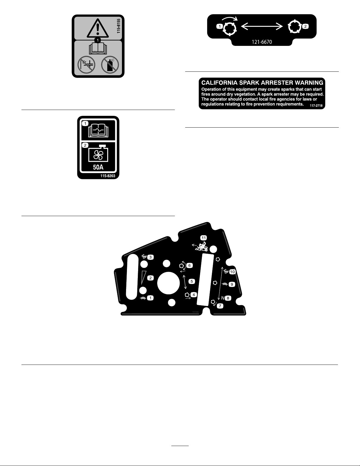
121–5171
1.Choke
2.Engine—start4.Engine—stop
1.Presspedaltounlock
3.Enginerun
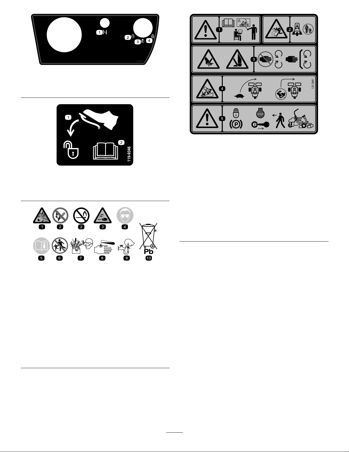
121–2641
1.Warning—readthe
Operator’sManual,do
notoperatethismachine
119-9346
2.ReadtheOperator's
Manualformore
information.
unlessyouaretrained.
2.Thrownobject
hazard—keepbystanders
asafedistancefromthe
machine.
3.Cutting/dismemberment
hazardofhandorfoot,
mowerblade—stayaway
frommovingparts;keep
allguardsandshieldsin
place.
4.Tippinghazard—slow
machinebeforeturning,
donotturnathighspeeds.
5.Warning—locktheparking
brake,stoptheengine
andremovetheignition
keybeforeleavingthe
machine.
BatterySymbols
Someorallofthesesymbolsareonyourbattery .
1.Explosionhazard
2.Nore,openames,or
smoking.
3.Causticliquid/chemical
burnhazard
4.Weareyeprotection.9.Flusheyesimmediately
5.ReadtheOperator’s
Manual.
6.Keepbystandersasafe
distancefromthebattery.
7.Weareyeprotection;
explosivegasescan
causeblindnessandother
injuries.
8.Batteryacidcancause
blindnessorsevereburns.
withwaterandgetmedical
helpfast.
10.Containslead;donot
discard.
10
Page 11
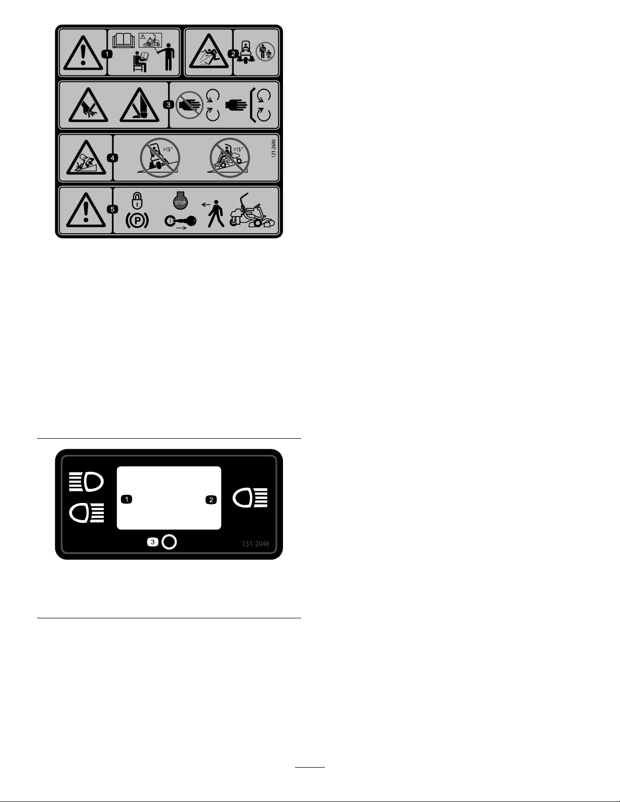
121–2640
1.Warning—readthe
Operator’sManual,do
notoperatethismachine
unlessyouaretrained.
2.Thrownobject
hazard—keepbystanders
asafedistancefromthe
machine
3.Cutting/dismemberment
hazardofhandorfoot,
mowerblade—stayaway
frommovingparts;keep
allguardsandshieldsin
place.
4.Tippinghazard—donot
driveacrossslopesgreater
than15degreesordown
slopesgreaterthan15
degrees.
5.Warning—locktheparking
brake,stoptheengine
andremovetheignition
keybeforeleavingthe
machine.
1.Doublelights
2.Singlelight
131-2046
3.Off
11
Page 12

Setup
LooseParts
Usethechartbelowtoverifythatallpartshavebeenshipped.
ProcedureDescription
1
2
3
4
5
6
7
Rollbar1
Bolt(1/2x3-3/4inches)
Flange-nut(1/2inch)
Seat-completionkit
Steeringwheel
Locknut(1-1/2inches)
Washer1
Steeringwheelcap
Nopartsrequired
Grass-baskethook
Flangebolts12
Gaugebar
Cuttingunit(model04613,04614,or
04615)
Cutting-unitupperweight
Hex-headbolts6
GrassBasket
Weightkit,121–6665(purchase
seperately)Note:notrequiredforunits
withthe3wheeldrivekitinstalled.
Qty.
4
4
1Installtheseattothebase.
1
1
1
–
6
1
3
3
3
1Addrearweight.
Installtherollbar.
Installthesteeringwheel.
Activateandchargethebattery.
Installthegrass-baskethooks.
Installthecuttingunits.
Use
8
Warningdecal121–26401
MediaandAdditionalParts
Description
Operator'sManual(machine)
EngineOperator'sManual(engine)
PartsCatalog
OperatorTrainingMaterials
Pre-deliveryInspectionSheet
Noiseratingcerticate
Certicateofcompliance
Ignitionkeys2
Qty.
InstallEUdecals,ifrequired.
Use
1
1
1
1
1
1
1
Readbeforeoperatingthemachine
Saveforfuturepartsordering
Viewbeforeoperatingthemachine
Saveforfuturereference
Starttheengine
12
Page 13
1
g014601
1
2
3
2
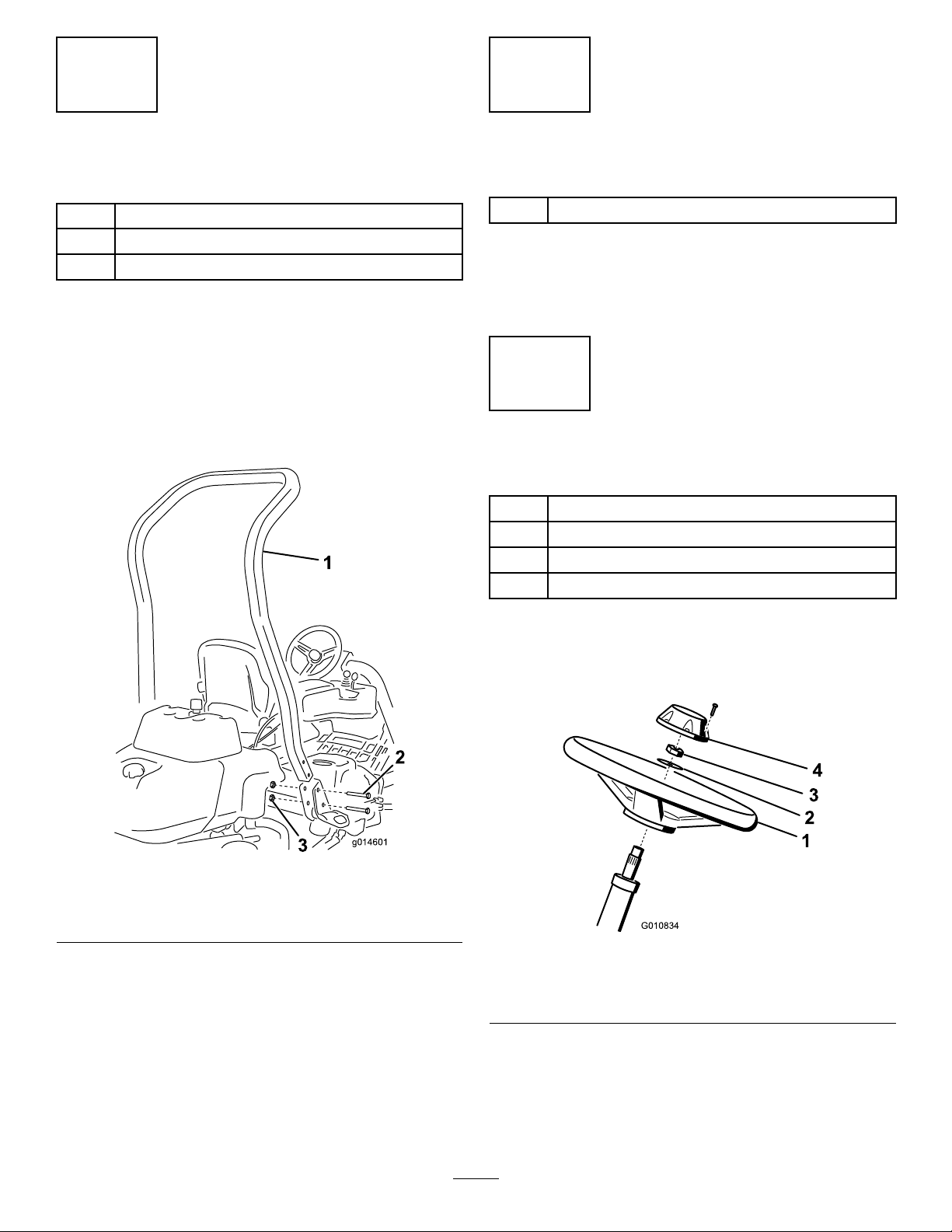
InstallingtheRollBar
Partsneededforthisprocedure:
1Rollbar
4
Bolt(1/2x3-3/4inches)
4
Flange-nut(1/2inch)
Procedure
1.Removethetopcratesupportfromthecrate.
2.Removetherollbarfromthecrate.
3.Installtherollbarintothepocketsoneachsideof
themachine,using4bolts(1/2x3-3/4inches)and4
ange-nuts(1/2inch)(Figure3).
InstallingtheSeat
Partsneededforthisprocedure:
1
Seat-completionkit
Procedure
Acquireyourdesiredseatkitfromyourdistributorandinstall
itasdirectedintheinstructionincludedwiththekit.
3
InstallingtheSteeringWheel
Partsneededforthisprocedure:
1
Steeringwheel
1
Locknut(1-1/2inches)
1Washer
1
Steeringwheelcap
Figure3
1.Rollbar
2.Bolt(1/2x3-3/4inches)
4.Torquethefastenersto136to149N-m(100to110
ft-lb).
3.Flange-nut(1/2inch)
Procedure
1.Slidethesteeringwheelontothesteeringshaft(Figure
4).
Figure4
1.Steeringwheel
2.Washer
2.Slidethewasherontothesteeringshaft(Figure4).
3.Securethesteeringwheeltotheshaftwithalocknut
andtightenitto27to35N-m(20to26ft-lb)(Figure4).
4.Installthecaptothesteeringwheelandsecureitwith6
bolts(Figure4).
3.Locknut
4.Cap
13
Page 14
4
ActivatingandChargingthe
Battery
NoPartsRequired
Procedure
Useonlyelectrolyte(1.265specicgravity)tollbattery
initially.
1.Removethefastenersandbatteryclampandliftout
thebattery.
Important:Donotaddelectrolytewhilethe
batteryisinthemachine.Y oucouldspillit,
causingcorrosion.
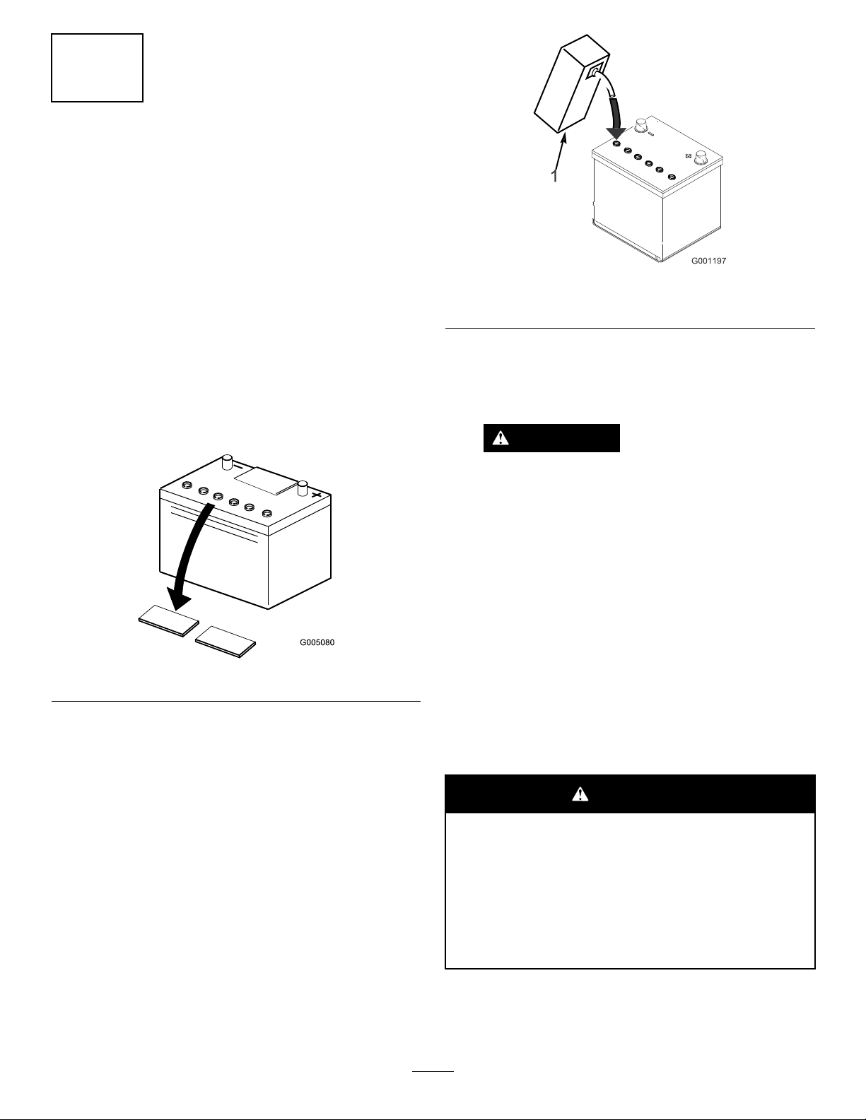
2.Cleanthetopofthebatteryandremovetheventcaps
(Figure5).
Figure5
Figure6
1.Electrolyte
4.Allowapproximately20to30minutesforthe
electrolytetosoakintotheplates.Fillasnecessaryto
bringtheelectrolytetowithinabout6mm(1/4inch)
ofthebottomofthellwell(Figure6).
WARNING
Chargingthebatteryproducesgassesthatcan
explode.
Neversmokenearthebatteryandkeepsparks
andamesawayfrombattery.
5.Connecta2to4ampbatterychargertothebattery
posts.Chargethebatteryfor2hoursat4ampsorfor
4hoursat2ampsuntilthespecicgravityis1.250or
higherandthetemperatureisatleast60°F(16°C)with
allcellsgassingfreely.
6.Whenthebatteryischarged,disconnectthecharger
fromtheelectricaloutletandbatteryposts.
3.Carefullylleachcellwithelectrolyteuntiltheplates
arecoveredwithabout6mm(1/4inch)ofuid(Figure
6).
Note:Afterthebatteryhasbeenactivated,add
onlydistilledwatertoreplacenormalloss,although
maintenance-freebatteriesshouldnotrequirewater
undernormaloperatingconditions.
WARNING
CALIFORNIA
Proposition65Warning
Batteryposts,terminals,andrelated
accessoriescontainleadandleadcompounds,
chemicalsknowntotheStateofCalifornia
tocausecancerandreproductiveharm.
Washhandsafterhandling.
14
Page 15
WARNING
Batteryterminalsormetaltoolscouldshort
againstmetaltractorcomponentscausing
sparks.Sparkscancausethebatterygassesto
explode,resultinginpersonalinjury.
•Whenremovingorinstallingthebattery,
donotallowthebatteryterminalstotouch
anymetalpartsofthetractor.
•Donotallowmetaltoolstoshortbetween
thebatteryterminalsandmetalpartsof
thetractor.
5
InstallingtheGrass-Basket Hooks
Partsneededforthisprocedure:
6
Grass-baskethook
12Flangebolts
WARNING
Failuretocorrectlyactivatethebatterymay
resultinbatterygassingand/orpremature
batteryfailure.
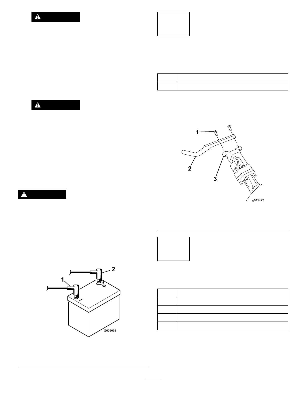
7.Placethebatteryonthebatterytrayandsecureitwith
thebatteryclampandfasternersremovedpreviously.
8.Installthepositivecable(red)tothepositive(+)
terminalandthenthenegativecable(black)tothe
negative(–)terminalofthebatteryandsecurethem
withtheboltsandnuts(Figure7).Slidetherubber
bootoverthepositiveterminaltopreventapossible
shortfromoccurring.
WARNING
Incorrectbatterycableroutingcoulddamagethe
tractorandcablescausingsparks.Sparkscancause
thebatterygassestoexplode,resultinginpersonal
injury.
•Alwaysdisconnectthenegative(black)battery
cablebeforedisconnectingthepositive(red)
cable.
•Alwaysconnectthepositive(red)batterycable
beforeconnectingthenegative(black)cable.
Procedure
Installthe6grass-baskethooksontotheendsofthe
suspension-armbarsusingthe12angebolts(Figure8).
Figure8
1.Flangebolt
2.Grass-baskethook
3.Suspension-armbar
6
1.Negative(-)
2.Positive(+)
Figure7
InstallingtheCuttingUnits
Partsneededforthisprocedure:
1
Gaugebar
3
Cuttingunit(model04613,04614,or04615)
3
Cutting-unitupperweight
6Hex-headbolts
3
GrassBasket
Procedure
Note:Whensharpening,settingtheheight-of-cut,or
performingothermaintenanceproceduresonthecutting
units,storethecuttingunitreelmotorsinthestoragelocation
15
Page 16

onthefrontofthesuspensionarmstopreventdamageto
g014596
1
2
2
1
2
g016294
3
g014602
1
2
them.
Important:Donotraisethesuspensiontothetransport
positionwhenthereelmotorsareintheholdersinthe
machineframe.Damagetothemotorsorhosescould
result.
Important:Wheneverthecuttingunithastobetipped
toexposebedknife/reel,propuprearofcuttingunitto
makesurenutsonbackendofbedbaradjustingscrews
arenotrestingonworksurface(Figure9).
Figure10
Figure9
1.Prop(notprovided)2.Bedknifeadjustingnut(2)
Note:Allcuttingunitsareshippedwiththecounterweight
mountedtotherightendandthemotormountanddrive
couplermountedtotheleftendofthecuttingunit.
1.Disconnectthecuttingunitpowerdisconnectcouplers;
refertoCuttingUnitPowerDisconnectConnectors
(page24).
CAUTION
Ifyoudonotdisconnectthepowertothe
cuttingunits,someonecouldaccidentally
startthecuttingunit,causingseriousinjury
tohandsandfeet.
Alwaysseparatethecuttingunitpower
disconnectcouplersbeforeworkingonthe
cuttingunits.
1.Cutting-untilweight(ip
over)
2.Upperweight
3.Hex-headbolts
5.Rotatetheweight180degreessothattheopenscrew
holesthatwereontheundersideoftheweightarenow
ontop.Installtheweighttothecuttingunitusingthe
boltsremovedpreviously.
6.Installanupperweighttothecuttingunitweightusing
2hexheadscrews(Figure10).
7.Ifinstallingthecentercuttingunit,liftuponthefoot
restandswingitup,allowingaccesstothecenter
cuttingunitposition(Figure11).
CAUTION
Thefootrestcanpinchngersifitfallsinto
theclosedposition.
Keepyourngersclearoftheareawherethe
footrestseatswhileitisopen.
2.Applygreasetotheinsidediameterofthedrivecoupler.
3.Thecuttingunitisshippedwithoutafrontroller.
Obtainaroller(Models04625,04626,or04627)from
yourlocalToroDistributor.Installtherollerusing
theloosepartssuppliedwiththecuttingunitand
installationinstructionsincludedwiththeroller.
4.Removethe2boltssecuringtheweighttothesideof
thecuttingunit(Figure10).
Figure11
1.Footrest—closed2.Footrest—open
8.Positionthecuttingunitunderthesuspensionarm.
16
Page 17

9.Withthelatchesonthesuspension-armbarpointing
g014609
1
2
3
g01461 1
1
2
up(i.e.,open)(Figure12),pushthesuspensionarm
downsothatthebartsoverthebaracrossthetopof
thecuttingunit(Figure13).
Figure12
1.Latch—closedposition3.Latch—openposition
2.Suspension-armbar
Figure14
Figure13
1.Suspension-armbar2.Cutting-unitbar
10.Closethelatchesdownandaroundthecutting-unitbar
andlocktheminplace(Figure12).
Note:A“click”canbeheardandfeltwhenthelatches
areproperlylockedinplace.
11.Coatthesplineshaftofthecutting-unitmotorwith
cleangrease(Figure14).
12.Insertthemotorintotheleftsideofthecuttingunit
(asviewedfromtheoperator'sposition)andpullthe
motor-retainingbaronthecuttingunittowardthe
motoruntilyouhearanaudible“click”frombothsides
ofthemotor(Figure14).
1.Reelmotor
2.Splineshaft
13.Mountagrassbasketontothebaskethooksonthe
suspensionarm.
14.Repeatthisprocedurefortheothercuttingunits.
15.Connectthecutting-unitpower-disconnectcouplers;
refertoCuttingUnitPowerDisconnectConnectors
(page24).
3.Cavity
4.Motor-retainingbar
7
AddingRearWeight
Partsneededforthisprocedure:
Weightkit,121–6665(purchaseseperately)Note:not
1
requiredforunitswiththe3wheeldrivekitinstalled.
Procedure
ThisunitcomplieswiththeANSIB71.4-2004andEN836
Standardswhenequippedwithweightkit121–6665.
Note:Iftheunitisequippedwithathreewheeldrivekit
additionalweightisnotrequiredtomeetANSIB71.4-2004
andEN836standards.
17
Page 18

8
g014674
1
2
3
4
5
6
7
8
InstallingEUDecals
Partsneededforthisprocedure:
1Warningdecal121–2640
Procedure
IfthismachinewillbeusedintheEU,afxthewarningdecal
121–2640overwarningdecal121–2641.
ProductOverview
Figure15
1.Engine
2.Rollbar6.Tractionpedal
3.Controlpanel
4.Seat
5.Steeringwheel
7.Footrest
8.Reelswithgrassbaskets
Controls
TractionPedal
Thetractionpedal(Figure16)has3functions:tomakethe
machinemoveforward,tomoveitbackward,andtostopthe
machine.Pressthetopofthepedaltomoveforwardandthe
bottomofthepedaltomovebackwardortoassistinstopping
whenmovingforward.Also,allowthepedaltomovetothe
Neutralpositiontostopthemachine.Foroperatorcomfort,
donotresttheheelofyourfootonreversewhenoperating
forward(Figure17).
18
Page 19

g014603
1
2
3
Figure16
G017975
1
3
2
4
5
1.Tractionpedal—forward3.Steeringarmlockingpedal
2.Tractionpedal—reverse
Figure17
Figure18
1.Ignitionswitch4.Throttle
2.Functional-controllever
3.Raise/LowerMowControl
5.InfoCenter
Raise/LowerMowControl
Movingthecontrol(Figure18)forwardduringoperation
lowersthecuttingunitsandstartsthereels.Pullbackonthe
controltostopthereelsandraisethecuttingunits.During
operationthereelscanbestoppedbypullingbackonthe
controlmomentarilyandreleasingit.Thisfeatureisknownas
Tap-offandisadjustableintheInfoCenter.Startthereelsby
movingthecontrolforward.
Functional-ControlLever
Groundspeedsareasfollows:
•3.2to8km/h(2to5mph)forwardmowingspeed
•16km/h(10mph)maximumtransportspeed
•4.0km/h(2.5mph)reversespeed
Steering-Arm-LockingPedal
Pressthepedal(Figure16)andraiseorlowerthesteering
armforoperatorcomfort,then,releasethepedaltolockthe
arminplace.
Note:Movethesteeringarmfullyforwardbeforelifting
theseat.
ThrottleControl
Thethrottlecontrol(Figure18)givestheoperatortheability
tocontrolthespeedoftheengine.Movingthethrottle
controltowardtheFastpositionincreasestheenginerpm;
movingthethrottlecontroltowardSlowwilldecreasethe
enginerpm.
Note:Thethrottlecontrolwillnotstoptheengine.
Thefunctionalcontrollever(Figure18)provides2traction
selectionsplusaNeutralposition.Itispermissibletoshift
frommowtotransportortransporttomow(nottoneutral)
whilethemachineisinmotion.Nodamagewillresult.
•RearPosition—neutralandbacklapping
•MiddlePosition—usedformowingoperation
•FrontPosition—usedfortransportoperation
IgnitionSwitch
Insertthekeyintotheswitch(Figure18)andturnitclockwise
asfaraspossibletotheStartpositiontostarttheengine.
Releasethekeyassoonastheenginestarts;thekeywillmove
totheOnposition.TurnthekeycounterclockwisetotheOff
positiontostoptheengine.
BacklapSwitch
Thebacklapswitchislocatedundertheplasticcoverto
theleftoftheseat.Usethebacklapswitch(Figure19)in
conjunctionwiththeraise/lowermowcontrolleverandthe
reelspeedcontrolforbacklappingthereels.
19
Page 20

G017943
2
2
7.5
7.5
7.5
7.5
7.5
7.5
10
10
15
15
C2
C2
1
2
Figure19
1
G017946
2
3
4
5
6
7
8
9
10
TORO
13.2
10,000.0
STOP
n/min
52.2V
10,000.0
n/min
52.2V
1200
100
170
240
1600
n/min
G017947
2
3
1
1.Backlapswitch—backlap
position
2.Backlapswitch—mow
position
UsingtheInfoCenterLCDDisplay
TheInfoCenterLCDdisplayshowsinformationaboutyour
machinesuchasthegeneratorstatus,thespeed,andvarious
diagnosticsandotherinformationaboutthemachineandthe
batterypack.Figure20andFigure21illustratethesplash
screenandmaininformationscreenoftheInfoCenter.You
canswitchbetweenthesplashscreenandmaininformation
screenatanytimebypressinganyoftheInfoCenterbuttons
andthenselectingtheappropriatedirectionalarrow.
Figure21
1.Functionalcontrolstatus
2.Functionalcontrolstatus
3.PTOspeed
•Enginerpm/status—indicatestheenginerpm.
•Faultlog—indicatesthatthereisacurrentfaultlogto
review.
•Generatorvoltage/status—indicatesthegenerator
voltage.
•Hourmeter—indicatesthetotalhoursthemachinehas
operated.Itstartstofunctionwheneverthekeyswitch
isrotatedtoOn.
•PTOspeed—indicatesthePTOspeed.
•Glowplug—indicatesthattheglowplugisactive.
•Batteryvoltage—indicatesthebatterypotentialinVolts.
•Coolanttemperature—indicatestheenginecoolant
temperatureineither°Cor°F .
•Functionalcontrolstatus—transportmodeisindicated
byarabbitandmowmodeisindicatedbyaturtle.
•Engineoilpressurelight—thisiconappearsiftheengine
oilpressuredropsbelowasafelevel.
•Menuaccess/backbutton—pressthisbuttontoaccess
theInfoCentermenus.Youcanuseittobackoutofany
Figure20
1.Batteryvoltage
2.Powerlight/faultindicator
3.Enginerpm/status
4.Faultlog9.Downbutton
5.Generatorvoltage/status10.Menuaccess/backbutton
6.GlowPlug
7.Hourmeter
8.Rightbutton
20
menuyouarecurrentlyusing.
•Downbutton—usethisbuttontoscrolldownmenus.
•Rightbutton—usethisbuttontoopenamenuwherea
rightarrowindicatesadditionalcontent.
Note:Thepurposeofeachbuttonmaychangedepending
onwhatisrequiredatthetime.Eachbuttonwillbelabeled
withanicondisplayingitscurrentfunction.
UsingtheMenus
ToaccesstheInfoCentermenusystem,pressthemenuaccess
buttonwhileatthemainscreen.Thiswillbringyoutothe
mainmenu.Refertothefollowingtablesforasynopsisof
theoptionsavailablefromthemenus:
Page 21

MainMenu
MenuItemDescription
FaultsTheFaultsmenucontains
ServiceTheServicemenucontains
DiagnosticsTheDiagnosticsmenu
SettingsTheSettingsmenuallows
AboutTheAboutmenuliststhe
Service
MenuItemDescription
Hours
CountsListsthenumberofpreheats
Diagnostics
MenuItemDescription
EngineRun
GlowplugsIndicatesifthefollowingitems
Fan
alistoftherecentmachine
faults.RefertotheService
ManualoryourAuthorized
ToroDistributorformore
informationontheFaults
menuandtheinformation
containedthere.
informationonthemachine
suchashoursofuseandother
similarnumbers.
listsvariousstatesthatthe
machinecurrentlyhas.You
canusethistotroubleshoot
certainissuesasitwillquickly
tellyouwhichmachine
controlsareonandwhichare
off.
youtocustomizeandmodify
congurationvariablesonthe
InfoCenterdisplay.
modelnumber,serialnumber,
andsoftwareversionofyour
machine.
Liststhetotalnumberofhours
thatthemachine,engine,
reels,backlap,andfanhave
beenon,aswellasthe
numberofhoursthemachine
hasbeentransportedand
overheated.
andstartsthemachinehas
experienced.
Indicatesifthefollowingitems
areactive:Keystart,keyrun,
joysticklower,joystickraise,
neutral,seatorparkingbrake,
OKrun,andRTRorETR.
areactive:Keystart,timeout
limited,andglowplugs.
Indicatesifthefanisactive
inthefollowinginstances:
Enginehightemp,oilhigh
temp,engineorhydraulichigh
temp,andfanon.
S1–S4Controlstheraisingand
ReelsEnable
Settings
MenuItemDescription
Units
Language
LCDBacklightControlsthebrightnessofthe
LCDContrastControlsthecontrastofthe
ProtectedMenus
ProtectionSettingsControlstheprotectedmenus.
ResetDefaultsResetstheInfoCenterto
RaiseDelay
LowerDelay
TapoffDelayControlsthetap-offdelay.
ReelSpeedControlsthereelspeed.
Backlaprpm
About
MenuItemDescription
Model
SNListstheserialnumberofthe
TEC5001Liststhesoftwarerevisionof
InfoCenterListsthesoftwarerevisionof
CU1Liststhesoftwarerevisionof
CU2Liststhesoftwarerevisionof
CU3Listthesoftwarerevisionof
GeneratorListstheserialnumberofthe
CANBus
loweringofthesolenoids.
IndicatesiftheeReelis
enabled.
Controlstheunitsusedonthe
InfoCenter.Themenuchoices
areEnglishorMetric.
Controlsthelanguageused
ontheInfoCenter.
LCDdisplay.
LCDdisplay.
Allowsthedistributor/engineer
toaccessprotectedmenusby
inputtingapasscode.
defaultsettings.
Controlstheraisedelaytime
forthecentercuttingunit.
Controlsthelowerdelayfor
thecentercuttingunit.
Controlsthebacklaprpm
speed.
Liststhemodelnumberofthe
machine.
machine.
themastercontroller .
theInfoCenter.
therstcuttingunit.
thesecondcuttingunit.
thethirdcuttingunit.
generator.
Liststhemachine
communicationbusstatus.
21
Page 22

CenterCuttingUnitRaise/LowerDelay
g014736
Theraiseandlowerdelaytimeforthecentercuttingmaybe
adjustedindependentlywiththeInfoCenter.Eachsetting
maybeadjustedfrom1to10accordingtothetablebelow .
Thefactorydefaultsettingis6(375ms)andisoptimizedfor
a3.8mphmowspeed.
3.Usingtheappropriategraph(SeeFigure22)for5,8,
11,or14bladecuttingunits,determinetheproperreel
speedsetting.
IncrementNumber
10.100
20.150
30.200
40.250
5
60.375
7
80.600
90.750
100.925
DelayTime(Seconds)
0.300
0.475
Tap-offDelay
Thetap-offdelayfeatureallowsthecuttingunitstoturnoff
withoutraising,andmaybeadjustedwiththeInfoCenter.The
delaysettingrepresentsthemaximumtimefortheraise/lower
joysticktoremainintheraisepositiontoactivatethisfeature.
Thefactorydefaultsettingis1whichdisablesthisfeature.
IncrementNumber
1
20.050
30.100
40.150
5
60.250
7
80.350
90.400
100.450
DelayTime(Seconds)
Off
0.200
0.300
Figure22
4.Tosetthereelspeed,ontheInfoCenteropentheMain
MenuandscrolldowntoSettings.
5.IntheSettingsmenu,scrolldowntoReelSpeedand
usethe±buttontosetthereelspeedtothedesired
number.
MachineCongurationPasscode
Thereare5operatingcongurationsettingsthatare
adjustablewithinthesettingmenuoftheInfoCenter:Raise
andlowerdelay,tap-offdelay,reelspeed,andbacklapspeed.
Thesesettingcanbeprotectedbyauserdenedpasscodeby
openingtheMainmenuandscrollingdowntotheSettings
menu.FindProtectSettingsandselectOn.
WhenprotectsettingOnisselectedtheuserisprompted
toentera4digitpasscode.Afterthepasscodeisset,the
keyswitchmustbeturnedoffandbackontoenableand
savethisfeature.Afterenablingtheprotectsettingsoption,
thecongurationsettingsarehiddenuntiltheuserdened
passcodeisentered.
Note:Iftheuserdenedpasscodeisforgotten,atemporary
passcodecanbeobtainedthroughyourauthorizedT oro
distributor.
SettingtheReelSpeed
Toachieveaconsistent,highquality–of–cutandauniform
aftercutappearance,itisimportantthatthereelspeedcontrol
becorrectlyset.
Adjustthereelspeedcontrolasfollows:
1.Selecttheheight-of-cutatwhichthecuttingunitsare
set.
2.Choosethedesiredgroundspeedbestsuitedfor
conditions.
DiagnosingtheFault-LogIndicator
Thefault-logindicatoriconappearsonthemainscreeninthe
eventofafaultinthemachine.Whenthisiconispresent
thereisanewlogentryintheFaultsmenuthatyouoryour
distributorcanusetoidentifytheproblem.
Foralistoffaults,refertoyourAuthorizedToroDistributor
ortheServiceManual.
22
Page 23

Seat-AdjustingLever
g014628
1
g01462 6
1
Theseat-adjustingleverislocatedonthefront,rightcorner
oftheseat(Figure23),allowingyoutoadjusttheseatfore
andaft.Pushthelevertotheleft(towardsthecenter),to
releasethelockandslidetheseat.
Note:Ifyouneedadditionaladjustmentontheseat,youcan
removethefourboltssecuringtheseattothebaseandmove
theseattothesecondsetofmountingholesprovided.
Figure24
1.Fuelshutoff(underthefueltank)
Figure23
1.Seat-adjustinglever
Note:Beforeliftingtheseat,slideittothefurthestback
positionandmovethesteeringarmfullyforward.
Fuel-ShutoffValve
Closethefuel-shutoffvalve(Figure24)behindtheseatand
underthefueltankwhenstoringortransportingthemachine
onatruckortrailer.
Parking-BrakeLever
Pulluponthebrakelever(Figure25)tosettheparkingbrake.
Disengageitbypullinguponthereleaselatchandlowering
thebrakehandle.Locktheparkingbrakeanytimeyouleave
themachine.
Figure25
1.Parking-brakelever2.Releaselatch
23
Page 24

CuttingUnitPowerDisconnect
Connectors
Beforeinstalling,removing,orworkingonthecutting
units,disconnectthecuttingunitsfromthepowersupply
byseparatingthecuttingunitpowerdisconnectconnectors
(Figure26),locatedatthebaseoftherolloverbarontheleft
sideofthetractionunit.Plugtheconnectorstogetherbefore
operatingthemachine.
Specications
Note:Specicationsanddesignaresubjecttochange
withoutnotice.
Widthofcut151cm(59.5inches)
Wheeltread
Wheelbase
Overalllength(w/baskets)249cm(98.0inches)
Overallwidth179cm(70.62inches)
Overallheight205cm(80.83inches)
128cm(50.5inches)
123cm(48.6inches)
Figure26
1.Cuttingunitpowerdisconnectconnector
CAUTION
Ifyoudonotdisconnectthepowertothecutting
units,someonecouldaccidentallystartthecutting
unit,causingseriousinjurytohandsandfeet.
Alwaysseparatethecuttingunitpowerdisconnect
connectorsbeforeworkingonthecuttingunits.
NetWeightw/reels(11Blade)Refertothetractionunit
serialtag(Figure1).
Attachments/Accessories
AselectionofToroapprovedattachmentsandaccessoriesis
availableforusewiththemachinetoenhanceandexpand
itscapabilities.ContactyourAuthorizedServiceDealeror
Distributororgotowww .Toro.comforalistofallapproved
attachmentsandaccessories.
24
Page 25

Operation
g014618
1
2
Note:Determinetheleftandrightsidesofthemachine
fromthenormaloperatingposition.
ThinkSafetyFirst
Pleasecarefullyreadallofthesafetyinstructionsandsymbols
inthesafetysection.Knowingthisinformationcouldhelp
youorbystandersavoidinjury.
Theuseofprotectiveequipment,suchasbutnotlimitedto,
foreyes,ears,feet,andheadisrecommended.
CheckingtheEngineOil
Theengineisshippedwithoilinthecrankcase;however,the
oillevelmustbecheckedbeforeandaftertheengineisrst
started.
Crankcasecapacityisapproximately3.7l(3.9quarts)with
thelter.
isnecessarytopermitventingwhenlling,which
preventsoilfromoverrunningintobreather.
Figure27
Usehigh-qualityengineoilthatmeetsthefollowing
specications:
•APIClassicationLevelRequired:CH–4,CI–4orhigher.
•Preferredoil:SAE10W–30
•Alternateoil:SAE15W–40
ToroPremiumEngineoilisavailablefromyourdistributorin
the10W–30viscosity .Seethepartscatalogforpartnumbers.
Note:Thebesttimetochecktheengineoiliswhenthe
engineiscoolbeforeithasbeenstartedfortheday.Ifithas
alreadybeenrun,allowtheoiltodrainbackdowntothe
sumpforatleast10minutesbeforechecking.Iftheoillevel
isatorbelowthe“add”markonthedipstick,addoiltobring
theoilleveltothe“full”mark.Donotoverll.Iftheoil
levelisbetweenthe“full”and“add”marks,nooiladdition
isrequired.
Important:Besuretokeeptheengineoillevelbetween
theupperandlowerlimitsontheoilgauge.Engine
failuremayoccurasaresultofoverllingorunder
llingtheengineoil.
1.Positionthemachineonalevelsurface.
2.Removethedipstickandwipeitwithacleanrag(Figure
28).Pushthedipstickintothetubeandmakesureit
isseatedfully.Removethedipstickfromthetubeand
checkthelevelofoil.Iftheoillevelislow,removethe
llercapfromthevalvecoverandslowlyaddenough
oiltoraisetheleveltotheFullmarkonthedipstick.
Addtheoilslowlyandchecktheleveloftenduringthis
process.Donotoverll.
Important:Makesurethatthedipstickisremoved
whilellingtheenginewithoil.Whenadding
engineoilorllingoil,there
betweentheoillldeviceandtheoilllholeinthe
valvecoverasshowninFigure27.Thisclearance
must be
clearance
1.Noteclearance
Figure28
1.Fillercap2.Dipstick
3.Replacethedipstick.
4.Startandruntheengineatidlefor30seconds,then
shuttheengineoff.Wait30seconds,thenrepeatsteps
2–3.
Important:Checkthelevelofoilevery8operating
hoursordaily.Changetheoilandlterinitially
aftertherst50hoursofoperation,thereafter
changetheoilandthelterevery150hours.
However,changetheoilmorefrequentlywhen
theengineisoperatedinextremelydustyordirty
conditions.
5.Installthellercapanddipstickrmlyinplace.
25
Page 26

FillingtheFuelTank
Useonlyclean,freshdieselfuelorbiodieselfuelswithlow
(<500ppm)orultralow(<15ppm)sulfurcontent.The
minimumcetaneratingshouldbe40.Purchasefuelin
quantitiesthatcanbeusedwithin180daystoensurefuel
freshness.
•Fuellterpluggingmaybeexpectedforatimeafter
convertingtobiodieselblends.
•Contactyourdistributorifyouwishformoreinformation
onbiodiesel
DANGER
Fueltankcapacity:22.7L(6USgallons)
Usesummergradedieselfuel(No.2-D)attemperatures
above-7°C(20°F)andwintergrade(No.1-DorNo.
1-D/2-Dblend)belowthattemperature.Useofwintergrade
fuelatlowertemperaturesprovideslowerashpointand
coldowcharacteristicswhichwilleasestartingandreduce
fuellterplugging.
Useofsummergradefuelabove-7°C(20°F)willcontribute
towardlongerfuelpumplifeandincreasedpowercompared
towintergradefuel.
DANGER
Undercertainconditions,dieselfuelandfuel
vaporsarehighlyammableandexplosive.Are
orexplosionfromfuelcanburnyouandothersand
cancausepropertydamage.
•Useafunnelandllthefueltankoutdoors,in
anopenarea,whentheengineisoffandiscold.
Wipeupanyfuelthatspills.
•Donotllthefueltankcompletelyfull.Add
fueltothefueltankuntilthelevelis6to13mm
(1/4to1/2inch)belowthebottomoftheller
neck.Thisemptyspaceinthetankallowsthe
fueltoexpand.
•Neversmokewhenhandlingfuel,andstayaway
fromanopenameorwherefuelfumesmaybe
ignitedbyaspark.
•Storefuelinaclean,sealed,safety-approved
container.
BiodieselReady
Thismachinecanalsouseabiodieselblendedfuelofup
toB20(20%biodiesel,80%petrodiesel).Thepetrodiesel
portionshouldbeloworultralowsulfur.Observethe
followingprecautions:
•Thebiodieselportionofthefuelmustmeetspecication
ASTMD6751orEN14214.
•TheblendedfuelcompositionshouldmeetASTMD975
orEN590.
•Paintedsurfacesmaybedamagedbybiodieselblends.
•UseB5(biodieselcontentof5%)orlesserblendsincold
weather.
•Monitorseals,hoses,gasketsincontactwithfuelasthey
maybedegradedovertime.
Incertainconditions,fuelisextremelyammable
andhighlyexplosive.Areorexplosionfromfuel
canburnyouandothersandcandamageproperty.
•Fillthefueltankoutdoors,inanopenarea,when
theengineiscold.Wipeupanyfuelthatspills.
•Donotllthefueltankcompletelyfull.Addfuel
tothefueltankuntilthelevelis25mm(1inch)
belowthebottomofthellerneck.Thisempty
spaceinthetankallowsfueltoexpand.
•Neversmokewhenhandlingfuel,andstayaway
fromanopenameorwherefuelfumesmaybe
ignitedbyaspark.
•Storefuelinanapprovedcontainerandkeepit
outofthereachofchildren.Neverbuymore
thana30-daysupplyoffuel.
•Alwaysplacefuelcontainersonthegroundaway
fromyourvehiclebeforelling
•Donotllfuelcontainersinsideavehicleoron
atruckortrailerbedbecauseinteriorcarpets
orplastictruckbedlinersmayinsulatethe
containerandslowthelossofanystaticcharge.
•Whenpractical,removegas-poweredequipment
fromthetruckortrailerandrefueltheequipment
withitswheelsontheground.
•Ifthisisnotpossible,thenrefuelsuchequipment
onatruckortrailerfromaportablecontainer
ratherthanfromafuel-dispensernozzle.
•Whenusingafuel-dispensernozzle,keepthe
nozzleincontactwiththerimofthefueltank
orcontaineropeningatalltimesuntilfuelingis
complete.
1.Cleanaroundthefuel-tankcap(Figure29).
26
Page 27

g014612
1
Figure29
g01461 3
1
2
3
4
1.Fuel-tankcap
2.Removethefuel-tankcap.
3.Fillthetankuntilthelevelis6to13mm(1/4to1/2
inch)belowthebottomofthellerneck.Donot
overll.Installthecap.
thecoolantatthebeginningofeachdaybeforestartingthe
engine.
CAUTION
Iftheenginehasbeenrunning,thepressurized,hot
coolantcanescapeandcauseburns.
•Donotopentheradiatorcapwhentheengine
isrunning.
•Usearagwhenopeningtheradiatorcap,and
openthecapslowlytoallowsteamtoescape.
1.Parkthemachineonalevelsurface.
2.Checkthecoolantlevel(Figure31).
Note:Itshouldbebetweenthelinesonthereserve
tankwhentheengineiscold.
4.Wipeupanyfuelthatmayhavespilled.
CheckingtheCoolingSystem
Thecapacityofthecoolingsystemisapproximately4.6L(4.9
quarts).RefertoCleaningtheRadiatorScreen(page44).
Figure30
Figure31
1.Reservetank
3.Ifthecoolantislow,removethereservetankcapand
adda50/50mixtureofwaterandpermanentethylene
glycolantifreeze.Donotoverll.
4.Installthereserve-tankcap.
CheckingtheHydraulic-Fluid Level
Beforeoperatingthemachineeachday ,checklevelofthe
hydraulicuidinthewhiteplasticwindowonthefrontofthe
hydraulic-uidreservoir(behindtheseatontheleftside).The
uidshouldbebetweenthelinesinthewindow;ifnot,add
anappropriateuidasdescribedinthefollowingsections:
1.Wingbolts3.Reservetank
2.Radiatorscreen
Thecoolingsystemislledwitha50/50solutionofwater
andpermanentethyleneglycolantifreeze.Checkthelevelof
4.Radiator-llcap
Themachinesreservoirislledatthefactorywith
approximately20.8L(5.5gallons)ofhighqualityhydraulic
uid.Checkthelevelofthehydraulicuidbefore
theengineisrststartedanddailythereafter.The
recommendedreplacementuidisasfollows:
27
Page 28

ToroPremiumAllSeasonHydraulicFluid(Availablein5
g014719
1
1
2
g016334
gallonpailsor55gallondrums.SeepartscatalogorToro
distributorforpartnumbers.)
Alternateuids:IftheTorouidisnotavailable,otheruids
maybeusedprovidedtheymeetallthefollowingmaterial
propertiesandindustryspecications.W edonotrecommend
theuseofsyntheticuid.Consultwithyourlubricant
distributortoidentifyasatisfactoryproduct
Note:Torowillnotassumeresponsibilityfordamage
causedbyimpropersubstitutions,souseonlyproducts
fromreputablemanufacturerswhowillstandbehindtheir
recommendation.
HighViscosityIndex/LowPourPointAnti-wearHydraulic
Fluid,ISOVG46
MaterialProperties:
Viscosity,ASTMD445cSt@40°C44to48
ViscosityIndexASTM
D2270
PourPoint,ASTMD97-34°Fto-49°F
IndustrySpecications:
VickersI-286-S(QualityLevel),VickersM-2950-S
(QualityLevel),DenisonHF-0,Vickers35VQ25(Eaton
ATS373-C)
cSt@100°C7.9to8.5
140to160
Important:TheISOVG46Multigradeuidhasbeen
foundtoofferoptimalperformanceinawiderangeof
temperatureconditions.Foroperationinconsistently
highambienttemperatures,65°F(18°C)to120°F
(49°C),ISOVG68hydraulicuidmayofferimproved
performance.
FillingtheHydraulicTank
1.Positionthemachineonalevelsurface.Makesurethe
machinehascooleddownsotheoiliscold.
2.Removethecapfromthereservoir(Figure32).
Figure32
1.Hydraulic-tankcap
3.Slowlyllthereservoirwiththeappropriatehydraulic
uiduntilthelevelisatorwithin6mm(0.25inch)of
thearrowinthesymbolnexttothewhitewindowin
thefrontofthereservoir(Figure33).Donotoverll.
PremiumBiodegradableHydraulicFluid-MobilEAL
EnviroSyn46H
Important:MobilEALEnviroSyn46Histheonly
syntheticbiodegradableuidapprovedbyT oro.This
uidiscompatiblewiththeelastomersusedinToro
hydraulicsystemsandissuitableforawide-range
oftemperatureconditions.Thisuidiscompatible
withconventionalmineraloils,butformaximum
biodegradabilityandperformancethehydraulicsystem
shouldbethoroughlyushedofconventionaluid.The
oilisavailablein19L(5-gallon)containersor55-gallon
drumsfromyourMobilDistributor.
Note:Manyhydraulicuidsarealmostcolorless,makingit
difculttospotleaks.Areddyeadditiveforthehydraulic
systemoilisavailablein20ml(2/3oz)bottles.Onebottle
issufcientfor15-22L(4-6gallons)ofhydraulicoil.Order
partno.44-2500fromyourauthorizedTorodistributor.This
reddyeisnotrecommendedforusewithbiodegradable
uids.
Important:Regardlessofhydraulicuidtypeused,any
machineusedformowingfairways,verticuttingorused
duringambienttemperaturesabove85°F(29°C)should
haveOilCoolerKit,PartNo.117-9314,installed.
Figure33
1.Whitewindowonthefront
ofthehydraulicreservoir
2.Filltowithinthisarea.
Important:Topreventsystemcontamination,
cleanthetopofthehydraulicuidcontainers
beforepuncturing.Ensurethepourspoutand
funnelareclean.
4.Installthereservoircap.Wipeupanyuidthatmay
havespilled.
Important:Checklevelofhydraulicuidbefore
engineisrststartedanddailythereafter.
28
Page 29

DrainingWaterfromtheFuel
g014720
1
2
CheckingtheReel-to-Bedknife
Filter
ServiceInterval:Beforeeachuseordaily
1.Positionthemachineonalevelsurfaceandstopthe
engine.
2.Placeadrainpanunderthefuellter.
3.Openthedrainplugonthefuellterapproximately
oneturnanddrainanyaccumulatedwater(Figure34).
Tightentheplugafterdraining.
Note:Becausetheaccumulatedwaterwillbemixed
withdieselfuel,drainthefuellterintoasuitable
containeranddisposeofitproperly.
Contact
Eachdaybeforeoperatingthemachine,checkthe
reel-to-bedknifecontact,regardlessifthequalityofcuthad
previouslybeenacceptable.Theremustbelightcontact
acrossthefulllengthofthereelandbedknife;referto
AdjustingtheReeltoBedknifeinthecuttingunitOperator’s
Manual.
Beforecheckingthereels,disconnectthecuttingunitpower
disconnectcouplers;refertoCuttingUnitPowerDisconnect
Connectors(page24).Connectthemwhennished.
CAUTION
Ifyoudonotdisconnectthepowertothecutting
units,someonecouldaccidentallystartthecutting
unit,causingseriousinjurytohandsandfeet.
Alwaysseparatethecuttingunitpowerdisconnect
couplersbeforeworkingonthecuttingunits.
Breaking-intheMachine
RefertotheEngineManualsuppliedwiththemachineforoil
changeandmaintenanceproceduresrecommendedduring
thebreak-inperiod.
Figure34
1.Fuellter
2.Drainplug
CheckingtheTirePressure
Thetiresareover-inatedatthefactoryforshipping
purposes.Reducethepressuretotheproperlevelsbefore
startingtheunit.
Varythetirepressureforall3wheels,dependinguponyour
turfconditions,fromaminimumof83toamaximumof110
kPa(12psito16psi).
CheckingtheTorqueofthe WheelNuts
WARNING
Failuretomaintainpropertorqueofthewheelnuts
couldresultinpersonalinjury.
Only8hoursofmowingoperationisrequiredforthebreak-in
period.
Sincethersthoursofoperationarecriticaltofuture
dependabilityofthemachine,monitoritsfunctionsand
performancecloselysothatminordifculties,whichcould
leadtomajorproblems,arenotedandcanbecorrected.
Inspectthemachinefrequentlyduringbreak-inforsignsof
oilleakage,loosefasteners,oranyothermalfunction.
Toensureoptimumperformanceofthebrakesystem,burnish
(break-in)thebrakesbeforeusingthemachine.Toburnish
thebrakes,rmlyapplythebrakesanddrivethemachineat
mowingspeeduntilthebrakesarehot,asindicatedbytheir
smell.Anadjustmenttothebrakesmayberequiredafter
break-in;refertoAdjustingtheBrakes.
Torquethewheelnutsto95to122N-m(70to90
ft-lb)after1-4hoursofoperationandagainafter
10hoursofoperation.Torquethenutsevery200
hoursthereafter.
29
Page 30

StartingandStoppingthe
g014602
1
2
InstallingandRemovingthe
Machine
Note:Inspecttheareasbeneaththemowerstobecertain
theyareclearofdebris.
StartingtheMachine
Important:Donotuseetherorothertypesofstarting
uid.
1.Besuretheparkingbrakeisset,theraise/lowermow
controlisdisengaged,andthefunctionalcontrolisin
theneutralposition.
2.Removeyourfootfromthetractionpedalandmake
surethepedalisintheneutralposition.
3.MovethethrottlelevertotheSlowposition.
4.InsertthekeyintotheswitchandrotateittoOn.Hold
itintheOnpositionuntiltheglowplugindicatorlight
goesoff(approximately6seconds).
5.ImmediatelyturntheignitionkeytotheStartposition.
Releasethekeywhentheenginestartsandallowitto
movetotheOnposition.Movethethrottlecontrol
toSlow .
Important:Topreventoverheatingofthestarter
motor,donotengagethestarterlongerthan10
seconds.After10secondsofcontinuouscranking,
wait60secondsbeforeengagingthestartermotor
again.
CuttingUnits
InstallingtheCuttingUnits
1.Disconnectthecuttingunitpowerdisconnectcouplers;
refertoCuttingUnitPowerDisconnectConnectors
(page24).
CAUTION
Ifyoudonotdisconnectthepowertothe
cuttingunits,someonecouldaccidentally
startthecuttingunit,causingseriousinjury
tohandsandfeet.
Alwaysseparatethecuttingunitpower
disconnectcouplersbeforeworkingonthe
cuttingunits.
2.Liftuponthefootrestandswingitopen,allowing
accesstothecentercuttingunitposition(Figure35).
CAUTION
Thefootrestcanpinchngersifitfallsinto
theclosedposition.
Keepyourngersclearoftheareawherethe
footrestseatswhileitisopen.
6.Allowtheenginetowarmupforafewminutesbefore
operating.
Important:Whentheengineisstartedfortherst
time,orafteranoverhauloftheengine,operate
themachineinforwardandreverseforoneto
twominutes.Turnthesteeringwheeltotheleft
andrighttocheckthesteeringresponse.Then
shuttheengineoff(seeStoppinginStartingand
StoppingtheEngine)andwaitforallmovingparts
tostop.Checkforoilleaks,loosepartsandany
othernoticeablemalfunctions.
StoppingtheMachine
1.MovethethrottlecontroltoSlow,disengagethe
raise/lowermowcontrol,andmovethefunctional
controltoneutral.
2.RotatethestarterkeytoOfftoshuttheengineoff.
Removethekeyfromtheswitchtopreventaccidental
starting.
3.Closethefuelshut-offvalvesbeforestoringthe
machine.
Figure35
1.Footrest—closed2.Footrest—open
3.Positionthecuttingunitunderthecentersuspension
arm.
4.Withthelatchesonthesuspension-armbarpointing
up(i.e.,open)(Figure36),pushthesuspensionarm
downsothatthebartsoverthebaracrossthetopof
thecuttingunit(Figure37).
30
Page 31

g014609
1
2
3
Figure36
g01461 1
1
2
1.Latch—closedposition3.Latch—openposition
2.Suspension-armbar
Figure38
Figure37
1.Suspension-armbar2.Cutting-unitbar
5.Closethelatchesdownandaroundthecutting-unitbar
andlocktheminplace(Figure36).
Note:A“click”canbeheardandfeltwhenthelatches
areproperlylockedinplace.
6.Coatthesplineshaftofthecuttingunitmotorwith
cleangrease(Figure38).
7.Insertthemotorintotheleftsideofthecuttingunit
(asviewedfromtheoperator'sposition)andpullthe
motorretainingbaronthecuttingunittowardthe
motoruntilyouhearanaudible“click”frombothsides
ofthemotor(Figure38).
1.Reelmotor
2.Splineshaft
3.Cavity
4.Motor-retainingbar
8.Mountagrassbasketontothebaskethooksonthe
suspensionarm.
9.Repeatthisprocedurefortheothercuttingunits.
10.Connectthecuttingunitpowerdisconnectcouplers;
refertoCuttingUnitPowerDisconnectConnectors
(page24).
RemovingtheCuttingUnits
1.Disconnectthecuttingunitpowerdisconnectcouplers;
refertoCuttingUnitPowerDisconnectConnectors
(page24).
CAUTION
Ifyoudonotdisconnectthepowertothe
cuttingunits,someonecouldaccidentally
startthecuttingunit,causingseriousinjury
tohandsandfeet.
Alwaysseparatethecuttingunitpower
disconnectcouplersbeforeworkingonthe
cuttingunits.
2.Parkthemachineonacleanlevelsurface,lower
thecuttingunitstothegrounduntilthesuspension
hydraulicsarefullyextended,stoptheengine,andset
31
theparkingbrake.
3.Pushthemotorretainingbaroutoftheslotsonthe
motortowardsthecuttingunitandremovethemotor
fromthecuttingunit.
Page 32

Figure39
1.Reelmotor2.Motor-retainingbar
4.Movethemotortothestoragelocationonthefrontof
thesuspensionarm(Figure40).
7.Rollthecuttingunitoutfromunderthesuspension
arm.
8.Repeatsteps3through7fortheothercuttingunits
asrequired.
9.Connectthecuttingunitpowerdisconnectcouplers;
refertoCuttingUnitPowerDisconnectConnectors
(page24).
Mowing
Note:Beforemowinggreenswiththemachine,nda
clearareaandpracticestartingandstopping,raisingand
loweringthecuttingunits,turning,etc.Thistrainingperiod
willbebenecialtotheoperatoringainingcondenceinthe
performanceofthemachine.
Note:Beforemowing,inspectthegreenfordebris,remove
theagfromthecup,anddeterminethebestdirectionto
mow .Basethedirectiontomowonthepreviousmowing
direction.Alwaysmowinanalternatepatternfromthe
previousmowingsothatthegrassbladeswillbelessaptto
laydownandthereforebedifculttotrapbetweenthereel
bladesandbedknife.
Figure40
Note:Whensharpening,settingtheheight-of-cut,
orperformingothermaintenanceproceduresonthe
cuttingunits,storethecuttingunitreelmotorsinthe
storagelocationonthefrontofthesuspensionarmsto
preventdamagetothem.
Important:Donotraisethesuspensiontothe
transportpositionwhenthereelmotorsareinthe
holdersinthemachineframe.Damagetothe
motorsorhosescouldresult.Ifyoumustmovethe
tractionunitwithoutthecuttingunitsinstalled,
securethemtothesuspensionarmsusingcable
ties.
5.Openthelatchesonthesuspension-armbarofthe
cuttingunityouareremoving(Figure36).
6.Disconnectthelatchesfromthecutting-unitbar.
1.ApproachthegreenwiththeshiftselectorintheNo.
1position.Startononeedgeofthegreensothatthe
ribbonprocedureofcuttingmaybeused.
Note:Thisholdscompactiontoaminimumand
leavesaneat,attractivepatternonthegreens.
2.Actuatethemowpedalasthefrontedgeofthegrass
basketscrosstheouteredgeofthegreen.
Note:Thisproceduredropsthecuttingunitstothe
turfandstartsthereels.
Important:Familiarizeyourselfwiththefactthat
theNo.1cuttingunitreelisdelayedandtherefore,
youshouldpracticetotrytogaintherequired
timingnecessarytominimizethecleanupmowing
operation.
3.Overlapaminimalamountwiththepreviouscuton
returnpasses.
Note:Toassistinmaintainingastraightlineacross
thegreenandkeepthemachineanequaldistancefrom
theedgeofthepreviouscut,establishanimaginary
sightlineapproximately1.8to3m(6to10ft)ahead
ofthemachinetotheedgeoftheuncutportionofthe
green(Figure41).
Somenditusefultoincludetheouteredgeofthe
steeringwheelaspartofthesightline;i.e.keepthe
steeringwheeledgealignedwithapointthatisalways
keptthesamedistanceawayfromthefrontofthe
machine(Figure41).
32
Page 33

G017821
1
3
2
Figure41
1.Alignmentmarker
2.Cutgrassonleft
4.Asthefrontofthebasketscrosstheedgeofthegreen,
depresstheliftpedal.
3.Keepfocalspot1.8-3
m(6-10ft)aheadofthe
machine.
Note:Attheendoftheperipherycut,momentarily
pullbackontheraise/lowermowlevertoshutthereels
offwithoutraisingthem.Continuemovingforward
untilthereelstopsrotating,then,driveoffthegreen
andraisethereels(Thiswillhelppreventdribbling
grassontothegreenwhileraisingthereels).
7.Emptythegrassbasketsofallclippingsbefore
transportingtothenextgreen.
Note:Heavywetclippingsplaceanunduestrainon
thebasketsandwilladdunnecessaryweighttothe
machine,therebyincreasingtheloadontheengine,
hydraulicsystem,brakes,etc.
DrivingtheMachinewithout Mowing
Makesurethecuttingunitsareinthefullupposition.Move
thefunctionalcontrollevertothetransportposition.Use
thebrakestoslowthemachinewhilegoingdownsteep
hillstoavoidlossofcontrol.Alwaysapproachroughareas
atareducedspeedandcrosssevereundulationscarefully.
Familiarizeyourselfwiththewidthofthemachine.Donot
attempttopassbetweenobjectsthatareclosetogetherso
thatcostlydamageanddowntimecanbeprevented.
Note:Thiswillstopthereelsandliftthecuttingunits.
Timingofthisprocedureisimportant,sothemowers
donotcutintothefringearea.However,asmuchof
thegreenaspossibleshouldbecuttominimizethe
amountofgrasslefttomowaroundtheouterperiphery
5.Cutdownonoperatingtimeandeaselineupforthe
nextpassbymomentarilyturningthemachineinthe
oppositedirection,thenturninginthedirectionofthe
uncutportion;i.e.,ifintendingtoturnright,rstswing
slightlyleft,thenright.
Note:Thiswillassistingettingthemachinemore
quicklyalignedforthenextpass.
Followthesameprocedureforturningintheopposite
direction.Itisagoodpracticetotrytomakeasshort
ofaturnaspossible.However,turninawiderarc
duringwarmerweathertominimizethepossibilityof
bruisingtheturf.
Important:Themachineshouldneverbestopped
onagreenwiththecuttingunitreelsoperating
asdamagetotheturfmayresult.Stoppingona
wetgreenwiththemachinemayleavemarksor
indentationsfromthewheels.
6.Finishcuttingthegreenbymowingtheouterperiphery
andreplacetheags.
TransportingtheMachine
Useaheavy-dutytrailerortrucktotransportthemachine.
Ensurethatthetrailerortruckhasallnecessarybrakes,
lighting,andmarkingasrequiredbylaw .Pleasecarefullyread
allthesafetyinstructions.Knowingthisinformationcould
helpyou,yourfamily,pets,orbystandersavoidinjury.
WARNING
Drivingonthestreetorroadwaywithoutturn
signals,lights,reectivemarkings,oraslow
movingvehicleemblemisdangerousandcanlead
toaccidentscausingpersonalinjury.
Donotdrivemachineonapublicstreetorroadway.
Totransportthemachine:
1.Ifusingatrailer,connectittothetowingvehicleand
connectthesafetychains.
2.Ifapplicable,connectthetrailerbrakes.
3.Loadthemachineontothetrailerortruck.
4.Stoptheengine,removethekey,setthebrake,and
closethefuelvalve.
Note:Besuretochangethedirectionofcuttingfrom
thepreviousmowing.Alwayskeepweatherandturf
conditionsinmindandbesuretochangethedirection
ofmowingfromthepreviouscutting.
5.Usethemetaltiedownloopsonthemachineto
securelyfastenthemachinetothetrailerortruckwith
straps,chains,cable,orropes.
33
Page 34

LoadingtheMachine
Useextremecautionwhenloadingthemachineontoatrailer
oratruck.Onefull-widthrampthatiswideenoughtoextend
beyondthereartiresisrecommendedinsteadofindividual
rampsforeachsideofthemachine(Figure42).Thelower
rearsectionofthemachineframeextendsbackbetweenthe
rearwheelsandservesasastopfortippingbackward.Having
afull-widthrampprovidesasurfacefortheframemembers
tocontactifthemachinestartstotipbackward.Ifitisnot
possibletouseonefull-widthramp,useenoughindividual
rampstosimulateafull-widthcontinuousramp.
Therampshouldbelongenoughsothattheanglesdonot
exceed15degrees(Figure42).Asteeperanglemaycause
mowercomponentstogetcaughtastheunitmovesfromthe
ramptothetrailerortruck.Steeperanglesmayalsocause
themachinetotipbackward.Ifloadingonornearaslope,
positionthetrailerortrucksothatitisonthedownside
oftheslopeandtherampextendsuptheslope.Thiswill
minimizetherampangle.Thetrailerortruckshouldbeas
levelaspossible.
Important:Donotattempttoturnthemachinewhile
ontheramp;youmaylosecontrolanddriveofftheside.
Figure42
1.Trailer3.Notgreaterthan15
degrees
2.Full-widthramp4.Full-widthramp—side
view
Avoidsuddenaccelerationwhendrivinguparampand
suddendecelerationwhenbackingdownaramp.Both
maneuverscancausethemachinetotipbackward.
WARNING
Loadingamachineontoatrailerortruckincreases
thepossibilityofbackwardtip-overandcouldcause
seriousinjuryordeath.
•Useextremecautionwhenoperatingamachine
onaramp.
•EnsurethattheROPSisintheuppositionwhile
usingtheseatbeltwhenloadingthemachine.
EnsurethattheROPSwillclearthetopofan
enclosedtrailer.
•Useonlyasingle,full-widthramp;donotuse
individualrampsforeachsideofthemachine.
•Ifindividualrampsmustbeused,useenough
rampstocreateanunbrokenrampsurfacewider
thanthemachine.
•Donotexceeda15-degreeanglebetweenthe
rampandthegroundorbetweentherampand
thetrailerortruck.
•Avoidsuddenaccelerationwhiledrivingthe
machineuparamp,toavoidtippingbackward.
InspectingandCleaningthe MachineafterMowing
Atthecompletionofthemowingoperation,thoroughlywash
themachinewithagardenhosewithoutanozzlesoexcessive
waterpressurewillnotcausecontaminationanddamageto
sealsandbearings.Neverwashawarmengineorelectrical
connectionswithwater.
Aftercleaning,itisrecommendedthemachinebeinspected
forpossiblehydraulicuidleaksanddamageorwearto
hydraulicandmechanicalcomponents.Thecuttingunits
shouldbecheckedforsharpness.Also,lubricatethetraction
pedalandbrakeshaftassemblywithSAE30Woilorspray
lubricanttodetercorrosionandhelpkeepthemachine
performingsatisfactorilyduringthenextmowingoperation.
TowingtheMachine
Incaseofanemergencythemachinecanbetowedforashort
distance(lessthan0.4km(1/4mile)).However,T orodoes
notrecommendthisasstandardprocedure.
Important:Donottowthemachinefasterthan3-5
km/h(2-3mph)becausethedrivesystemmaybe
damaged.Ifthemachinemustbemovedaconsiderable
distance,transportitonatruckortrailer.
•Avoidsuddendecelerationwhilebacking
themachinedownaramp,toavoidtipping
backward.
1.Locatethebypassvalveonthepumpandrotateitso
thattheslotisvertical(Figure43).
34
Page 35

g014627
1
Figure43
1.Bypassvalve—slotshowninclosed(horizontal)position
2.Beforestartingtheengine,closethebypassvalveby
rotatingitsothattheslotishorizontal(Figure43).Do
notstarttheenginewhenthevalveisopen.
35
Page 36

Maintenance
Note:Determinetheleftandrightsidesofthemachinefromthenormaloperatingposition.
Note:LookingforanElectricalSchematicorHydraulicSchematicforyourmachine?Downloadafreecopyoftheschematicby
visitingwww .T oro.comandsearchingforyourmachinefromtheManualslinkonthehomepage.
CAUTION
Ifyouleavethekeyintheignitionswitch,someonecouldaccidentlystarttheengineandseriouslyinjure
youorotherbystanders.
Removethekeyfromtheignition.
RecommendedMaintenanceSchedule(s)
MaintenanceService
Interval
Afterthersthour
Aftertherst8hours
Aftertherst50hours
Beforeeachuseordaily
Every25hours
Every50hours
Every150hours
Every200hours
MaintenanceProcedure
•Checkthetorqueofthewheelnuts.
•Checkthetorqueofthewheelnuts.
•Checkthetensiononthealternatorbelt.
•Changetheengineoilandlter.
•Changethehydraulic-oillter.
•Checktheenginerpm(atidleandfullthrottle).
•Checktheengineoil.
•Cleandebrisoffoftheradiatorscreenandradiator.Cleanhourlyifconditionsare
extremelydustyanddirty.
•Checkthehydraulic-uidlevel.
•Drainwaterfromthefuellter.
•Checkthereel-to-bedknifecontact.
•Checkthehydrauliclinesandhoses.
•Checkthebatteryelectrolytelevel.(Ifthemachineisinstorage,checkevery30
days.)
•Checkthebatterycableconnections.
•Changetheengineoilandlter.
•Checkthetorqueofthewheelnuts.
•Servicetheaircleanerlter(morefrequentlywhenoperatingconditionsaredusty
ordirty).
Every400hours
Every800hours
Every2years
•Greasethegeneratorbelttensioner.
•Replacethefuellter.
•Changethehydraulicoil,lter,andtankbreather.
•Checktheenginerpm(atidleandfullthrottle).
•Checkthevalveclearance.
•Checkthefuellinesandconnections.
•Replacemovinghoses.
•Drainandushthecoolingsystem.
Important:Refertoyourengineoperator’smanualforadditionalmaintenanceprocedures.
36
Page 37

DailyMaintenanceChecklist
Duplicatethispageforroutineuse.
Fortheweekof: MaintenanceCheckItem
Checkthesafetyinterlock
operation.
Checktheinstrument
operation
Checkthebrakeoperation.
Checkthefuellter/water
separator.
Checkthefuellevel.
Checktheengineoillevel.
Cleanthescreenand
radiator.
Inspecttheairlter.
Checkanyunusualengine
noises.
Checkthereel-to-bedknife
adjustment.
Checkthehydraulichoses
fordamage.
Checkforuidleaks.
Checkthetirepressure.
Checktheheight-of-cut
adjustment.
Touch-updamagedpaint.
Mon.Tues.Wed.Thurs.Fri.
Sat.Sun.
NotationforAreasofConcern
Inspectionperformedby:
ItemDate
Information
37
Page 38

Lubrication
g016344
g014614
1
2
3
EngineMaintenance
GreasingtheGeneratorBelt Tensioner
ServiceInterval:Every400hours
LubricatethegreasettingregularlywithNo.2
general-purpose,lithium-basegrease.
1.Wipethegreasettingcleansothatforeignmatter
cannotbeforcedintothebearingorbushing(Figure
44).
ServicingtheAirCleaner
ServiceInterval:Every200hours
•Checktheair-cleanerbodyfordamagewhichcouldcause
anairleak.Replaceifdamaged.Checkthewholeintake
systemforleaks,damageorloosehoseclamps.
•Servicetheair-cleanerlterbefore200hoursifthe
engineperformancesuffersduetoextremelydusty,dirty
conditions.Changingtheairlterbeforeitisnecessary
onlyincreasesthechanceofdirtenteringtheenginewhen
thelterisremoved.
•Besurethecoverisseatedcorrectlyandsealswiththe
aircleanerbody.
1.Releasethelatchessecuringtheaircleanercovertothe
aircleanerbody(Figure45).
Figure44
Thegreasettingislocatedbehindtheseatontheinner,
rightsideofthemachine.
2.Pumpgreaseintothebearingorbushinguntilthe
greaseisvisible.Wipeupexcessgrease.
Figure45
1.Air-cleanerbody3.Air-cleanercover
2.Airlter
2.Removethecoverfromtheair-cleanerbody .Before
removingthelter,uselowpressureair(40psi,clean
anddry)tohelpremovelargeaccumulationsofdebris
packedbetweenoutsideofprimarylterandthe
canister.Avoidusinghighpressureairwhichcould
forcedirtthroughthelterintotheintaketract.This
cleaningprocesspreventsdebrisfrommigratinginto
theintakewhentheprimarylterisremoved.
3.Removeandreplacetheprimarylter.Cleaningofthe
usedelementisnotrecommendedduetothepossibility
ofdamagetotheltermedia.Inspectthenewlterfor
shippingdamage,checkingthesealingendofthelter
andthebody.Donotuseadamagedelement.Insert
thenewlterbyapplyingpressuretotheouterrimof
theelementtoseatitinthecanister.Donotapply
pressuretotheexiblecenterofthelter.
38
Page 39

4.Cleanthedirtejectionportlocatedintheremovable
g014754
1
g014615
1
cover.Removetherubberoutletvalvefromthecover,
cleanthecavityandreplacetheoutletvalve.
3.Screwthelteronbyhanduntilthegasketcontacts
thelteradapter,thentighten1/2to3/4turnfurther.
Donotovertighten.
5.Installthecoverorientingtherubberoutletvalveina
downwardposition—betweenapproximately5:00to
7:00whenviewedfromtheend.
6.Securethelatches(Figure45).
ChangingtheEngineOiland Filter
ServiceInterval:Aftertherst50hours
Every150hours
1.Removethedrainplugandletoilowintoadrainpan.
Whentheoilstops,installthedrainplug(Figure46).
4.Addoiltothecrankcase;refertoCheckingtheEngine
Oil(page25).
5.Disposeoftheusedoilproperly.
Figure46
1.Drainplug
2.Removetheoillter(Figure47).Applyalightcoatof
cleanoiltothenewltergasket.
Figure47
1.Oillter
39
Page 40

FuelSystem
g01462 6
1
g014720
1
2
Maintenance
ServicingtheFuelFilter/Water Separator
ServiceInterval:Every800hours
ServicingtheFuelFilter
1.Closethefuel-shutoffvalve(Figure48)belowthefuel
tank.
Figure49
1.Fuel-shutoffvalve
Figure48
1.Fuellter/waterseparator
canister
5.Unscrewtheltercanisteranddisposeofitaccording
tolocalregulations.
6.Screwthelteronbyhanduntilthegasketcontactsthe
lteradapter,thentighten1/2to3/4turnfurther.
7.Makesurethelter-drainplugisclosed.Openthe
fuel-shutoffvalve.
2.Filter-drainplug
InspectingtheFuelLinesand Connections
ServiceInterval:Every2years
Inspectthefuellinesfordeterioration,damage,orloose
connections.
2.Cleantheareawheretheltercanistermounts(Figure
49).
3.Placeadrainpanunderthefuellter.
4.Openthelter-drainplug(Figure49).
40
Page 41

ElectricalSystem
Maintenance
ServicingtheBattery
WARNING
CALIFORNIA
Proposition65Warning
Batteryposts,terminals,andrelated
accessoriescontainleadandleadcompounds,
chemicalsknowntotheStateofCalifornia
tocausecancerandreproductiveharm.
Washhandsafterhandling.
Voltage:12V ,530ColdCrankingAmps
Thebatteryelectrolytelevelmustbeproperlymaintainedand
thetopofthebatterykeptclean.lfthemachineisstoredina
locationwheretemperaturesareextremelyhigh,thebattery
willrundownmorerapidlythanifthemachineisstoredin
alocationwheretemperaturesarecool.
Maintainthecelllevelwithdistilledordemineralizedwater.
Donotllthecellsabovethebottomofthesplitringinside
eachcell.
DANGER
Batteryelectrolytecontainssulfuricacidwhichisa
deadlypoisonandcausessevereburns.
WARNING
Batteryterminalsormetaltoolscouldshortagainst
metaltractorcomponentscausingsparks.Sparks
cancausethebatterygassestoexplode,resulting
inpersonalinjury.
•Whenremovingorinstallingthebattery,donot
allowthebatteryterminalstotouchanymetal
partsofthetractor.
•Donotallowmetaltoolstoshortbetweenthe
batteryterminalsandmetalpartsofthetractor.
WARNING
Incorrectbatterycableroutingcoulddamagethe
tractorandcablescausingsparks.Sparkscancause
thebatterygassestoexplode,resultinginpersonal
injury.
Ifcorrosionoccursattheterminals,disconnect
thecables,negative(-)cablerst,andscrape
theclampsandterminalsseparately.Reconnect
thecables,positive(+)cablerst,andcoatthe
terminalswithpetroleumjelly.
•Alwaysdisconnectthenegative(black)battery
cablebeforedisconnectingthepositive(red)
cable.
•Alwaysconnectthepositive(red)batterycable
beforeconnectingthenegative(black)cable.
•Donotdrinkelectrolyteandavoidcontactwith
skin,eyesorclothing.Wearsafetyglassesto
shieldyoureyesandrubberglovestoprotect
yourhands.
•Fillthebatterywherecleanwaterisalways
availableforushingtheskin.
Keepthetopofthebatterycleanbywashingitperiodically
withabrushdippedinammoniaorbicarbonateofsoda
solution.Flushthetopsurfacewithwateraftercleaningit.
Donotremovethellcapswhilecleaningthebattery.
Thebatterycablesmustbetightontheterminalstoprovide
goodelectricalcontact.
StoringtheBattery
Ifthemachinewillbestoredmorethan30days,removethe
batteryandchargeitfully.Eitherstoreitontheshelforon
themachine.Leavethecablesdisconnectedifitisstoredon
themachine.Storethebatteryinacoolatmospheretoavoid
quickdeteriorationofthechargeinthebattery.Toprevent
thebatteryfromfreezing,makesureitisfullycharged.The
specicgravityofafullychargedbatteryis1.265–1.299.
41
Page 42

LocatingtheFuses
g014617
1
2
Thefusesarelocatedundertheseat(Figure50)andunderthe
rightarmcover(Figure51).
Figure50
1.Fuses
2.50Afuseforradiatorfan
(behindpartsillustrated)
Figure51
1.Fuses
FuseLayout
35A
35A
35A
FuseLayout
LiftReel
Starter
10A7.5A
Run
10A7.5A
LightsDiag.Lights
LeakDetector
15A7.5A
E-ReelEnable
OverTemp
ReelEngage
Lift/Lower
Fan
Start/Run
Glow
ECMLogic
Power
2A
JumpStartingtheMachine
Ifthemachineneedstobejumpstarted,thealternatepositive
post(locatedonthestartersolenoid)canbeusedinsteadof
thepositivebatterypost(Figure52).
Figure52
1.Alternatepositivebatterypost
42
Page 43

DriveSystem
g014616
1
2
g015494
1
AdjustingtheTransportSpeed
Maintenance
AdjustingtheTransmission forNeutral
Ifthemachinecreepswhenthetractioncontrolpedalisin
theneutralposition,theneutralreturnmechanismmustbe
adjusted.
1.Blockupundertheframesothatoneofthefront
wheelsisoffoftheoor.
Note:Note:Ifmachineisequippedwitha3wheel
drivekit,alsoraiseandblockrearwheel.
2.Starttheengine,movethethrottletoSlow,andcheck
thefrontwheelthatisoffoftheoor;itmustnotbe
rotating.
3.Ifthewheelisrotating,stoptheengineandproceed
asfollows:
A.Loosenthenutsecuringtheeccentrictothetop
ofthehydrostat(Figure53).
Thetractionpedalisadjustedformaximumtransportspeed
atthefactory,butanadjustmentmayberequiredifthepedal
reachesfullstrokebeforeitcontactsthepedalstop,orifa
decreaseintransportspeedisdesired.
Pressdownonthetractionpedal.Ifthepedalcontacts
thestop(Figure54)beforetensionisfeltonthecable,an
adjustmentisrequired:
Figure54
1.Pedalstop
1.Loosenangeheadlocknutssecuringthepedalstopto
theoorplate(Figure54).
2.Adjustthepedalstopsoitcontactsthepedalrodand
tightenthenuts.
Figure53
1.Eccentric2.Locknut
B.MovethefunctionalcontrollevertoNeutraland
thethrottletoSlow.Starttheengine.
C.Rotatetheeccentricuntilcreepdoesnotoccurin
eitherdirection.Whenthewheelstopsrotating,
tightenthenutlockingtheeccentricandthe
adjustment(Figure53).Verifytheadjustment
withthethrottleintheSlowandFastposition.
Note:Ifthewheelstillturnswhentheeccentric
isatthemaximumadjustment,contactyour
AuthorizedServiceDistributororrefertothe
ServiceManualforfurtheradjustment.
43
Page 44

AdjustingtheMowingSpeed
g014625
1
2
3
g01461 3
1
2
3
4
CoolingSystem
Themowspeedissetto3.8mphatthefactory.
Theforwardmovingspeedcanbeadjustedfrom0to8km/h
(0to5mph).
1.Loosenthejamnutonthetrunnionbolt(Figure55).
2.Loosenthenutsecuringthelockandmowbrackets
onthepedalpivot.
Maintenance
CleaningtheRadiatorScreen
Topreventthesystemfromoverheating,theradiatorscreen
andradiatormustbekeptclean.Checkandcleanthe
screenandradiatordailyor,ifnecessary,hourly.Cleanthese
componentsmorefrequentlyindusty,dirtyconditions.
1.Removetheradiatorscreen(Figure56).
Figure55
1.Jamnut3.Trunnionbolt
2.Nut
3.Rotatethetrunnionboltclockwisetoreducethe
mowingspeedandcounterclockwisetoincreasethe
mowingspeed.
4.Tightenthejamnutonthetrunnionboltandthenut
onthepedalpivottolocktheadjustment(Figure55).
Checktheadjustmentandadjustasrequired.
Figure56
1.Wingbolts
2.Radiatorscreen4.Radiatorcap
2.Workingfromthefansideoftheradiator,blowoutthe
radiatorwithcompressedair.
3.Cleanthescreenandinstallit.
3.Overowtank
44
Page 45

BrakeMaintenance
g014755
1
2
3
BeltMaintenance
AdjustingtheBrakes
Ifthebrakefailstoholdthemachinewhileparked,youcan
adjustthebrakesusingthebulkheadttingnearthebrake
drum;contactyourAuthorizedServiceDistributororreferto
theServiceManualformoreinformation.
AdjustingtheAlternatorBelt
ServiceInterval:Aftertherst8hours
Makesurethebeltisproperlytensionedtoensureproper
operationofthemachineandpreventunnecessarywear.
1.Stoptheengine,settheparkingbrake,andremovethe
ignitionkey .
2.Applymoderatethumbpressuretothebeltbetween
thepulleys(10kgor22lb).Thebeltshoulddeect7
to9mm(0.28to0.35inches).Ifnot,completethe
followingproceduretoadjustthebelttension:
Figure57
1.Alternatorbelt—applypessurehere
2.Alternator
3.Adjustingstrap
A.Loosentheboltssecuringthealternatortothe
engineandadjustingstrap.
B.Inspectthebeltforwearordamageandreplaceif
itisworn.
C.Usingaleverplacedbetweenthealternatorand
theengineblock,pullthealternatorouttoobtain
thecorrectbelttensionandtightenthebolts.
45
Page 46

HydraulicSystem
g014619
1
Maintenance
ChangingtheHydraulicOil andFilter
ServiceInterval:Aftertherst50hours
Every800hours
Iftheoilbecomescontaminated,contactyourlocalToro
distributorbecausethesystemmustbeushed.Contaminated
oillooksmilkyorblackwhencomparedtocleanoil.
1.Cleantheareaaroundtheltermountingarea(Figure
58).Placeadrainpanunderthelterandremovethe
lter.
Note:Iftheoilisnotgoingtobedrained,disconnect
andplugthehydrauliclinegoingtothelter.
CheckingtheHydraulicLines andHoses
WARNING
Hydraulicuidescapingunderpressurecan
penetrateskinandcauseinjury.
•Makesureallhydraulicuidhosesandlinesare
ingoodconditionandallhydraulicconnections
andttingsaretightbeforeapplyingpressureto
thehydraulicsystem.
•Keepyourbodyandhandsawayfrompin
holeleaksornozzlesthatejecthighpressure
hydraulicuid.
•Usecardboardorpapertondhydraulicleaks.
•Safelyrelieveallpressureinthehydraulicsystem
beforeperforminganyworkonthehydraulic
system.
•Getimmediatemedicalhelpifuidisinjected
intoskin.
Figure58
1.Hydraulic-oillter
2.Fillthereplacementlterwiththeappropriatehydraulic
uid,lubricatethesealinggasket,andhandturnituntil
thegasketcontactsthelterhead.Thentighten3/4
turnfurther.Theltershouldnowbesealed.
3.Fillthehydraulicreservoirwithhydraulicoil;referto
FillingtheHydraulicTank(page28).
Checkthehydrauliclinesandhosesdailyforleaks,kinked
lines,loosemountingsupports,wear,loosettings,weather
deterioration,andchemicaldeterioration.Makeallnecessary
repairsbeforeoperating.
4.Startthemachineandrunitatidlefor3to5minutes
tocirculatetheuidandremoveanyairtrappedin
thesystem.
5.Stopthemachine,rechecktheuidlevelandreplenish
asrequired.
6.Disposeoftheoilandlterproperly.
46
Page 47

CuttingUnitMaintenance
G017943
2
2
7.5
7.5
7.5
7.5
7.5
7.5
10
10
15
15
C2
C2
1
2
engine.Aftercompletingadjustments,repeatsteps4
through9.
BacklappingtheReels
WARNING
Contactwiththereelsorothermovingpartscan
resultinpersonalinjury.
•Keepngers,hands,andclothingawayfromthe
reelsorothermovingparts.
•Neverattempttoturnthereelsbyhandorfoot
whiletheengineisrunning.
1.Positionthemachineonalevelsurface,lowerthe
cuttingunits,stoptheengine,engagetheparkingbrake.
2.Removetheplasticcovertotheleftsideoftheseat.
3.Makeinitialreeltobedknifeadjustmentsappropriate
forbacklappingonallcuttingunitswhicharetobe
backlapped;refertotheCuttingUnitOperator’ sManual.
4.Starttheengineandrunatlowidlespeed.Iftheengine
stalls,increasetheenginespeed.
5.SwitchtheBacklapSwitchtothereverse(R)position
(Figure59).
12.Repeattheprocedureforallcuttingunitsyouwantto
backlap.
13.Whennished,returnthebacklapswitchtotheforward
(F)position,replacethecover,andwashalllapping
compoundoffofthecuttingunits.Adjustcuttingunit
reeltobedknifeasneeded.Movethecuttingunitreel
speedcontroltothedesiredmowingposition.
Important:Ifthebacklapswitchisnotreturned
totheforward(F)positionafterbacklapping,the
cuttingunitswillnotraiseorfunctionproperly.
Figure59
1.Backlapswitch—reverse
position
2.Backlapswitch—mow
position
6.OntheInfoCenterpulluptheMainMenuandscroll
downtoSettings.
7.IntheSettingsmenuscrolldowntoBacklaprpmand
usethe±buttontoselectthedesiredbacklapspeed.
8.Withthefunctionalcontrolleverintheneutralposition,
movetheRaise/LowerMowcontrolforwardtostart
thebacklappingoperationonthedesignatedreels.
9.Applylappingcompoundwithalonghandlebrush.
Neveruseashorthandledbrush.
10.Ifthereelsstallorbecomeerraticwhilebacklapping,
selectahigherreelspeedsettinguntilthespeed
stabilizes.
11.Tomakeanadjustmenttothecuttingunitswhile
backlapping,turnthereelsoffbymovingthe
Raise/LowerMowcontrolrearwardandstopthe
47
Page 48

Storage
Ifyouwishtostorethemachineforalongperiodoftime,the
followingstepsshouldbeperformedpriortostorage:
1.Removeaccumulationsofdirtandoldgrassclippings.
Sharpenthereelsandbedknives,ifnecessary;referto
theCuttingUnitOperator'sManual.Usearustpreventive
onbedknivesandreelblades.Greaseandoilall
lubricationpoints;refertoLubrication(page38).
2.Blockupthewheelstoremoveanyweightonthetires.
3.Drainandreplacethehydraulicuidandlterand
inspectthehydrauliclinesandttings.Replace,if
necessary;refertoChangingtheHydraulicOiland
Filter(page46)andCheckingtheHydraulicLinesand
Hoses(page46).
4.Allfuelshouldberemovedfromthefueltank.Runthe
engineuntilitstopsfromlackoffuel.Replacethefuel
lter;refertoServicingtheFuelFilter(page40).
5.Whiletheengineisstillwarm,draintheoilfromthe
crankcase.Rellitwithfreshoil;refertoChangingthe
EngineOilandFilter(page39).
6.Cleandirtandchafffromthecylinder,cylinderhead
ns,andblowerhousing.
7.Removethebatteryandchargeitfully.Eitherstore
itontheshelforonthemachine.Leavethecables
disconnectedifitisstoredonthemachine.Store
thebatteryinacoolatmospheretoavoidquick
deteriorationofthechargeinthebattery.
8.Ifpossible,storethemachineinawarm,drylocation.
48
Page 49

Notes:
49
Page 50

Notes:
50
Page 51

InternationalDistributorList
Distributor:
AgrolancKft
BalamaPrimaEngineeringEquip.HongKong85221552163
B-RayCorporation
CascoSalesCompany
CeresS.A.CostaRica
CSSCTurfEquipment(pvt)Ltd.SriLanka
CyrilJohnston&Co.
CyrilJohnston&Co.RepublicofIreland
EquiverMexico525553995444ParklandProductsLtd.NewZealand6433493760
FemcoS.A.Guatemala
ForGarderOU
G.Y .K.CompanyLtd.
GeomechanikiofAthensGreece
GolfinternationalTurizm
GuandongGoldenStarChina
HakoGroundandGardenSweden
HakoGroundandGarden
HayterLimited(U.K.)
HydroturfInt.CoDubai
HydroturfEgyptLLC
IrrimacPortugal351212388260ToroEuropeNVBelgium3214562960
IrrigationProductsInt'lPvtLtd.India0091442449
JeanHeybroekb.v.Netherlands31306394611VictusEmakPoland48618238369
Country:
Hungary3627539640
Korea82325512076
PuertoRico7877888383
NorthernIreland442890813121
Estonia3723846060
Japan81726325861
Turkey902163365993Riversa
Norway4722907760
UnitedKingdom441279723444
UnitedArabEmirates97143479479T-MarktLogisticsLtd.Hungary3626525500
Egypt2025194308ToroAustraliaAustralia61395807355
PhoneNumber:Distributor:
5062391138
94112746100
442890813121
5024423277
30109350054
862087651338
4635100000
4387
Country:
MaquiverS.A.Colombia
MaruyamaMfg.Co.Inc.
Mountelda.s.CzechRepublic
Mountelda.s.Slovakia
MunditolS.A.
NormaGarden
OslingerTurfEquipmentSA
OyHakoGroundandGarden
Ab
Perfetto
PratoverdeSRL.
Prochaska&Cie
RTCohen2004Ltd.
LelyTurfcare
SolvertS.A.S.
SpyprosStavrinidesLimitedCyprus
SurgeSystemsIndiaLimited
ValtechMorocco21253766
Japan81332522285
Argentina54114821
Russia74954116120
Ecuador59342396970
Finland35898700733
Poland48618208416
Italy390499128
Austria4312785100
Israel97298617979
Spain
Denmark4566109200
France331308177
India911292299901
Phone
Number:
5712364079
420255704
220
420255704
220
9999
128
34952837500
00
35722434131
3636
EuropeanPrivacyNotice
TheInformationToroCollects
ToroWarrantyCompany(Toro)respectsyourprivacy.Inordertoprocessyourwarrantyclaimandcontactyouintheeventofaproductrecall,weaskyou
tosharecertainpersonalinformationwithus,eitherdirectlyorthroughyourlocalT orocompanyordealer.
TheT orowarrantysystemishostedonserverslocatedwithintheUnitedStateswhereprivacylawmaynotprovidethesameprotectionasapplies
inyourcountry.
BYSHARINGYOURPERSONALINFORMATIONWITHUS,YOUARECONSENTINGTOTHEPROCESSINGOFYOURPERSONALINFORMA TION
ASDESCRIBEDINTHISPRIV ACYNOTICE.
TheWayT oroUsesInformation
Toromayuseyourpersonalinformationtoprocesswarrantyclaims,tocontactyouintheeventofaproductrecallandforanyotherpurposewhichwetell
youabout.ToromayshareyourinformationwithT oro'safliates,dealersorotherbusinesspartnersinconnectionwithanyoftheseactivities.Wewillnot
sellyourpersonalinformationtoanyothercompany.Wereservetherighttodisclosepersonalinformationinordertocomplywithapplicablelawsand
withrequestsbytheappropriateauthorities,tooperateoursystemsproperlyorforourownprotectionorthatofotherusers.
RetentionofyourPersonalInformation
Wewillkeepyourpersonalinformationaslongasweneeditforthepurposesforwhichitwasoriginallycollectedorforotherlegitimatepurposes
(suchasregulatorycompliance),orasrequiredbyapplicablelaw .
Toro'sCommitmenttoSecurityofYourPersonalInformation
Wetakereasonableprecautionsinordertoprotectthesecurityofyourpersonalinformation.Wealsotakestepstomaintaintheaccuracyandcurrent
statusofpersonalinformation.
AccessandCorrectionofyourPersonalInformation
Ifyouwouldliketorevieworcorrectyourpersonalinformation,pleasecontactusbyemailatlegal@toro.com.
AustralianConsumerLaw
AustraliancustomerswillnddetailsrelatingtotheAustralianConsumerLaweitherinsidetheboxoratyourlocalT oroDealer.
374-0269RevH
Page 52

ToroGeneralCommercialProductWarranty
ATwo-YearLimitedWarranty
ConditionsandProductsCovered
TheToroCompanyanditsafliate,T oroWarrantyCompany,pursuant
toanagreementbetweenthem,jointlywarrantyourT oroCommercial
product(“Product”)tobefreefromdefectsinmaterialsorworkmanship
fortwoyearsor1500operationalhours*,whicheveroccursrst.This
warrantyisapplicabletoallproductswiththeexceptionofAerators
(refertoseparatewarrantystatementsfortheseproducts).Wherea
warrantableconditionexists,wewillrepairtheProductatnocosttoyou
includingdiagnostics,labor,parts,andtransportation.Thiswarranty
beginsonthedatetheProductisdeliveredtotheoriginalretailpurchaser.
*Productequippedwithanhourmeter.
InstructionsforObtainingWarrantyService
YouareresponsiblefornotifyingtheCommercialProductsDistributoror
AuthorizedCommercialProductsDealerfromwhomyoupurchasedthe
Productassoonasyoubelieveawarrantableconditionexists.Ifyouneed
helplocatingaCommercialProductsDistributororAuthorizedDealer,or
ifyouhavequestionsregardingyourwarrantyrightsorresponsibilities,
youmaycontactusat:
ToroCommercialProductsServiceDepartment
ToroWarrantyCompany
811 1LyndaleAvenueSouth
Bloomington,MN55420-1196
952–888–8801or800–952–2740
E-mail:commercial.warranty@toro.com
OwnerResponsibilities
AstheProductowner,youareresponsibleforrequiredmaintenanceand
adjustmentsstatedinyourOperator'sManual.Failuretoperformrequired
maintenanceandadjustmentscanbegroundsfordisallowingawarranty
claim.
ItemsandConditionsNotCovered
Notallproductfailuresormalfunctionsthatoccurduringthewarranty
periodaredefectsinmaterialsorworkmanship.Thiswarrantydoesnot
coverthefollowing:
•Productfailureswhichresultfromtheuseofnon-T ororeplacement
parts,orfrominstallationanduseofadd-on,ormodiednon-Toro
brandedaccessoriesandproducts.Aseparatewarrantymaybe
providedbythemanufactureroftheseitems.
•Productfailureswhichresultfromfailuretoperformrecommended
maintenanceand/oradjustments.Failuretoproperlymaintainyour
ToroproductpertheRecommendedMaintenancelistedinthe
Operator’sManualcanresultinclaimsforwarrantybeingdenied.
•ProductfailureswhichresultfromoperatingtheProductinanabusive,
negligent,orrecklessmanner.
•Partssubjecttoconsumptionthroughuseunlessfoundtobedefective.
Examplesofpartswhichareconsumed,orusedup,duringnormal
Productoperationinclude,butarenotlimitedto,brakepadsand
linings,clutchlinings,blades,reels,rollersandbearings(sealedor
greasable),bedknives,sparkplugs,castorwheelsandbearings,tires,
lters,belts,andcertainsprayercomponentssuchasdiaphragms,
nozzles,andcheckvalves,etc.
•Failurescausedbyoutsideinuence.Conditionsconsideredtobe
outsideinuenceinclude,butarenotlimitedto,weather,storage
practices,contamination,useofunapprovedfuels,coolants,lubricants,
additives,fertilizers,water,orchemicals,etc.
•Failureorperformanceissuesduetotheuseoffuels(e.g.gasoline,
diesel,orbiodiesel)thatdonotconformtotheirrespectiveindustry
standards.
•Normalnoise,vibration,wearandtear ,anddeterioration.
•Normal“wearandtear”includes,butisnotlimitedto,damagetoseats
duetowearorabrasion,wornpaintedsurfaces,scratcheddecalsor
windows,etc.
Parts
Partsscheduledforreplacementasrequiredmaintenancearewarranted
fortheperiodoftimeuptothescheduledreplacementtimeforthatpart.
Partsreplacedunderthiswarrantyarecoveredforthedurationofthe
originalproductwarrantyandbecomethepropertyofT oro.T orowillmake
thenaldecisionwhethertorepairanyexistingpartorassemblyorreplace
it.T oromayuseremanufacturedpartsforwarrantyrepairs.
DeepCycleandLithium-IonBatteryWarranty:
DeepcycleandLithium-Ionbatterieshaveaspeciedtotalnumberof
kilowatt-hourstheycandeliverduringtheirlifetime.Operating,recharging,
andmaintenancetechniquescanextendorreducetotalbatterylife.Asthe
batteriesinthisproductareconsumed,theamountofusefulworkbetween
chargingintervalswillslowlydecreaseuntilthebatteryiscompletelyworn
out.Replacementofwornoutbatteries,duetonormalconsumption,
istheresponsibilityoftheproductowner.Batteryreplacementmaybe
requiredduringthenormalproductwarrantyperiodatowner’sexpense.
Note:(Lithium-Ionbatteryonly):ALithium-Ionbatteryhasapartonly
proratedwarrantybeginningyear3throughyear5basedonthetime
inserviceandkilowatthoursused.RefertotheOperator'sManualfor
additionalinformation.
MaintenanceisatOwner’sExpense
Enginetune-up,lubrication,cleaningandpolishing,replacementoflters,
coolant,andcompletingrecommendedmaintenancearesomeofthe
normalservicesT oroproductsrequirethatareattheowner’sexpense.
GeneralConditions
RepairbyanAuthorizedToroDistributororDealerisyoursoleremedy
underthiswarranty.
NeitherTheToroCompanynorToroWarrantyCompanyisliablefor
indirect,incidentalorconsequentialdamagesinconnectionwiththe
useoftheToroProductscoveredbythiswarranty,includingany
costorexpenseofprovidingsubstituteequipmentorserviceduring
reasonableperiodsofmalfunctionornon-usependingcompletion
ofrepairsunderthiswarranty.ExceptfortheEmissionswarranty
referencedbelow,ifapplicable,thereisnootherexpresswarranty.All
impliedwarrantiesofmerchantabilityandtnessforusearelimitedto
thedurationofthisexpresswarranty.
Somestatesdonotallowexclusionsofincidentalorconsequential
damages,orlimitationsonhowlonganimpliedwarrantylasts,sotheabove
exclusionsandlimitationsmaynotapplytoyou.Thiswarrantygivesyou
speciclegalrights,andyoumayalsohaveotherrightswhichvaryfrom
statetostate.
Noteregardingenginewarranty:
TheEmissionsControlSystemonyourProductmaybecoveredby
aseparatewarrantymeetingrequirementsestablishedbytheU.S.
EnvironmentalProtectionAgency(EP A)and/ortheCaliforniaAirResources
Board(CARB).Thehourlimitationssetforthabovedonotapplytothe
EmissionsControlSystemWarranty.RefertotheEngineEmissionControl
WarrantyStatementsuppliedwithyourproductorcontainedintheengine
manufacturer’sdocumentationfordetails
CountriesOtherthantheUnitedStatesorCanada
CustomerswhohavepurchasedT oroproductsexportedfromtheUnitedStatesorCanadashouldcontacttheirT oroDistributor(Dealer)toobtain
guaranteepoliciesforyourcountry ,province,orstate.IfforanyreasonyouaredissatisedwithyourDistributor'sserviceorhavedifcultyobtaining
guaranteeinformation,contacttheT oroimporter.
374-0253RevC
 Loading...