

Page 1

FormNo.3385-965RevA
g014597
Greensmaster
®
3320TriFlex
TractionUnit
ModelNo.04530—SerialNo.314004001andUp
™
Registeratwww.T oro.com.
OriginalInstructions(EN)
*3385-965*A
Page 2
ThisproductcomplieswithallrelevantEuropeandirectives;
g014685
1
fordetails,pleaseseetheseparateproductspecicDeclaration
ofConformity(DOC)sheet.
WARNING
CALIFORNIA
Proposition65Warning
Thisproductcontainsachemicalorchemicals
knowntotheStateofCaliforniatocausecancer,
birthdefects,orreproductiveharm.
Theengineexhaustfromthisproduct
containschemicalsknowntotheStateof
Californiatocausecancer,birthdefects,
orotherreproductiveharm.
Figure1
Important:Thisengineisnotequippedwithaspark
arrestermufer.ItisaviolationofCaliforniaPublic
ResourceCodeSection4442touseoroperatetheengine
onanyforest-covered,brush-covered,orgrass-covered
land.Otherstatesorfederalareasmayhavesimilarlaws.
Introduction
Thismachineisaride-on,reel-bladelawnmowerintended
tobeusedbyprofessional,hiredoperatorsincommercial
applications.Itisprimarilydesignedforcuttinggrasson
well-maintainedlawnsinparks,golfcourses,sportselds,
andoncommercialgrounds.Itisnotdesignedforcutting
brush,mowinggrassandothergrowthalongsidehighways,
orforagriculturaluses.
Readthisinformationcarefullytolearnhowtooperateand
maintainyourproductproperlyandtoavoidinjuryand
productdamage.Youareresponsibleforoperatingthe
productproperlyandsafely.
YoumaycontactTorodirectlyatwww .Toro.comforproduct
andaccessoryinformation,helpndingadealer,ortoregister
yourproduct.
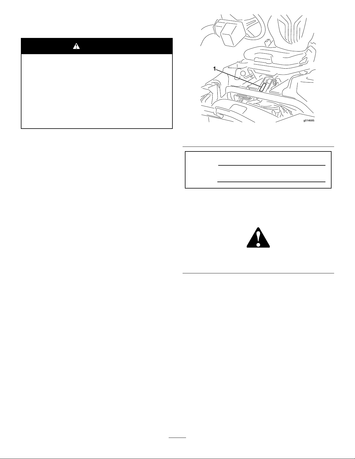
1.Modelandserialnumberlocation
ModelNo.
SerialNo.
Thismanualidentiespotentialhazardsandhassafety
messagesidentiedbythesafetyalertsymbol(Figure2),
whichsignalsahazardthatmaycauseseriousinjuryordeath
ifyoudonotfollowtherecommendedprecautions.
Figure2
1.Safetyalertsymbol
Thismanualuses2wordstohighlightinformation.
Importantcallsattentiontospecialmechanicalinformation
andNoteemphasizesgeneralinformationworthyofspecial
attention.
Wheneveryouneedservice,genuineT oroparts,oradditional
information,contactanAuthorizedServiceDealerorToro
CustomerServiceandhavethemodelandserialnumbersof
yourproductready.Figure1identiesthelocationofthe
modelandserialnumbersontheproduct.Writethenumbers
inthespaceprovided.
©2014—TheToro®Company
8111LyndaleAvenueSouth
Bloomington,MN55420
Contactusatwww.Toro.com.
2
PrintedintheUSA
AllRightsReserved
Page 3

Contents
Introduction..................................................................2
Safety...........................................................................4
SafeOperatingPractices...........................................4
ToroMowerSafety..................................................6
SoundPowerLevel..................................................7
SoundPressureLevel...............................................7
VibrationLevel......................................................7
SafetyandInstructionalDecals.................................8
Setup...........................................................................11
1InstallingtheRollBar...........................................12
2InstallingtheSeat.................................................12
3InstallingtheSteeringWheel..................................13
4ActivatingandChargingtheBattery........................13
5InstallingtheOptionalOilCooler...........................14
6InstallingtheGrassBasketHooks..........................15
7InstallingtheCuttingUnits...................................15
8AddingRearWeight.............................................17
9InstallingEUDecals.............................................17
ProductOverview.........................................................18
Controls...............................................................18
Specications........................................................25
Attachments/Accessories........................................25
Operation....................................................................26
ThinkSafetyFirst...................................................26
CheckingtheEngineOil..........................................26
FillingtheFuelTank...............................................26
CheckingtheHydraulicFluidLevel...........................27
CheckingtheReel-to-BedknifeContact.....................28
CheckingtheTirePressure......................................28
CheckingtheTorqueoftheWheelNuts.....................28
Breaking-intheMachine..........................................28
StartingtheEngine.................................................29
CheckingtheSafetyInterlockSystem........................29
InstallingandRemovingtheCuttingUnits.................30
TrainingPeriod......................................................32
Mowing................................................................32
TransportingtheMachine........................................33
InspectingandCleaningAfterMowing......................33
TowingtheMachine...............................................33
Maintenance.................................................................34
RecommendedMaintenanceSchedule(s)......................34
DailyMaintenanceChecklist....................................35
Lubrication...............................................................36
GreasingtheMachine.............................................36
EngineMaintenance..................................................36
ServicingtheAirCleaner.........................................36
ChangingtheEngineOilandFilter...........................37
ReplacingtheSparkPlugs........................................37
FuelSystemMaintenance...........................................38
ReplacingtheFuelFilter..........................................38
InspectingtheFuelLinesandConnections.................38
ElectricalSystemMaintenance....................................38
ServicingtheBattery...............................................38
ServicingtheFuses.................................................39
DriveSystemMaintenance.........................................39
AdjustingtheTransmissionforNeutral.....................39
AdjustingtheTransportSpeed.................................40
AdjustingtheMowingSpeed....................................40
BrakeMaintenance....................................................41
AdjustingtheBrakes...............................................41
HydraulicSystemMaintenance....................................41
ChangingtheHydraulicOilandFilter........................41
CheckingtheHydraulicLinesandHoses....................42
CuttingUnitMaintenance...........................................42
BacklappingtheReels.............................................42
Storage........................................................................43
3
Page 4

Safety
ThismachinemeetsorexceedsCENstandardEN
836:1997,ISOstandard5395:1990,andANSIB71.4-2012
specicationsineffectatthetimeofproductionwhen54
kg(119lb)ofweightisaddedtotherearwheel.
Note:Theadditionofattachmentsmadebyother
manufacturersthatdonotmeetAmericanNationalStandards
Institutecerticationwillcausenoncomplianceofthis
machine.
Improperuseormaintenancebytheoperatororowner
canresultininjury.Toreducethepotentialforinjury,
complywiththesesafetyinstructionsandalwayspay
attentiontothesafetyalertsymbol(Figure2),which
meansCaution,Warning,orDanger—personalsafety
instruction.Failuretocomplywiththeinstructionmay
resultinpersonalinjuryordeath.
SafeOperatingPractices
ThefollowinginstructionsareadaptedfromCENstandard
EN836:1997,ISOstandard5395:1990,andANSI
B71.4-2012.
Training
•ReadtheOperator’sManualandothertrainingmaterial
carefully.Befamiliarwiththecontrols,safetysigns,and
theproperuseoftheequipment.
•Iftheoperatorormechaniccannotreadthelanguage
ofthismanual,itistheowner’sresponsibilitytoexplain
thismaterialtothem.
•Neverallowchildrenorpeopleunfamiliarwiththese
instructionstouseorservicethemower.Local
regulationsmayrestricttheageoftheoperator.
•Nevermowwhilepeople,especiallychildren,orpetsare
nearby.
•Keepinmindthattheoperatororuserisresponsiblefor
accidentsorhazardsoccurringtootherpeopleortheir
property.
•Donotcarrypassengers.
•Alldriversandmechanicsshouldseekandobtain
professionalandpracticalinstruction.Theowneris
responsiblefortrainingtheusers.Suchinstructionshould
emphasize:
–theneedforcareandconcentrationwhenworking
withride-onmachines;
–controlofaride-onmachineslidingonaslopewill
notberegainedbytheapplicationofthebrake.The
mainreasonsforlossofcontrolare:
◊insufcientwheelgrip;
◊beingdriventoofast;
◊inadequatebraking;
◊thetypeofmachineisunsuitableforthetask;
◊lackofawarenessoftheeffectofground
conditions,especiallyslopes.
◊Theowner/usercanpreventandisresponsible
foraccidentsorinjuriesoccurringtopeople,or
damagetoproperty.
Preparation
•Whilemowing,alwayswearsubstantialfootwear,long
trousers,hardhat,safetyglasses,andhearingprotection.
Longhair,looseclothing,orjewelrymaygettangled
inmovingparts.Donotoperatetheequipmentwhen
barefootorwearingopensandals.
•Thoroughlyinspecttheareawheretheequipmentisto
beusedandremoveallobjectswhichmaybethrownby
themachine.
•Replacefaultysilencers/mufers.
•Evaluatetheterraintodeterminewhataccessoriesand
attachmentsareneededtoproperlyandsafelyperform
thejob.Onlyuseaccessoriesandattachmentsapproved
bythemanufacturer.
•Checkthatoperator’spresencecontrols,safetyswitches
andshieldsareattachedandfunctioningproperly.Donot
operateunlesstheyarefunctioningproperly.
Operation
•Donotoperatetheengineinaconnedspacewhere
dangerouscarbonmonoxidefumescancollect.
•Mowonlyindaylightoringoodarticiallight.
•Beforeattemptingtostarttheengine,disengageallblade
attachmentclutches,shiftintoneutral,andengagethe
parkingbrake.
•Rememberthereisnosuchthingasasafeslope.Travel
ongrassslopesrequiresparticularcare.T oguardagainst
overturning:
–donotstoporstartsuddenlywhengoingupor
downhill;
–machinespeedsshouldbekeptlowonslopesand
duringtightturns;
–stayalertforhumpsandhollowsandotherhidden
hazards;
–nevermowacrossthefaceoftheslope,unlessthe
mowerisdesignedforthispurpose.
•Stayalertforholesintheterrainandotherhiddenhazards.
•Watchoutfortrafcwhencrossingornearroadways.
•Stopthebladesfromrotatingbeforecrossingsurfaces
otherthangrass.
•Whenusinganyattachments,neverdirectdischargeof
materialtowardbystandersnorallowanyonenearthe
machinewhileinoperation.
•Neveroperatethemachinewithdamagedguards,shields,
orwithoutsafetyprotectivedevicesinplace.Besureall
4
Page 5

interlocksareattached,adjustedproperly ,andfunctioning
properly.
•Donotchangetheenginegovernorsettingsoroverspeed
theengine.Operatingtheengineatexcessivespeedmay
increasethehazardofpersonalinjury.
•Beforeleavingtheoperator’ sposition:
–stoponlevelground;
–disengagethepowertake-offandlowerthe
attachments;
–changeintoneutralandsettheparkingbrake;
–stoptheengineandremovethekey.
•Disengagedrivetoattachmentswhentransportingornot
inuse.
•Stoptheengineanddisengagedrivetoattachment:
–beforerefuelling;
–beforeremovingthegrasscatcher/catchers;
–beforemakingheightadjustmentunlessadjustment
canbemadefromtheoperator’sposition.
–beforeclearingblockages;
–beforechecking,cleaningorworkingonthemower;
–afterstrikingaforeignobjectorifanabnormal
vibrationoccurs.Inspectthemowerfordamage
andmakerepairsbeforerestartingandoperatingthe
equipment.
•Reducethethrottlesettingbeforestoppingtheengine
and,iftheengineisprovidedwithafuelshut-offvalve,
turnthefueloffattheconclusionofmowing.
•Keephandsandfeetawayfromthecuttingunits.
•Lookbehindanddownbeforebackinguptobesureof
aclearpath.
•Slowdownandusecautionwhenmakingturnsand
crossingroadsandsidewalks.Stopthereelswhennot
mowing.
•Donotoperatethemowerundertheinuenceofalcohol
ordrugs.
•Lightningcancausesevereinjuryordeath.Iflightning
isseenorthunderisheardinthearea,donotoperate
themachine;seekshelter.
•Usecarewhenloadingorunloadingthemachineintoa
trailerortruck.
•Usecarewhenapproachingblindcorners,shrubs,trees,
orotherobjectsthatmayobscurevision.
•Becertainthattheseatbeltcanbereleasedquicklyin
theeventofanemergency.
•Checktheareatobemowedandneverfolddowna
foldingROPSinareaswherethereareslopes,dropoffs
orwater.
•Checkcarefullyforoverheadclearances(i.e.branches,
doorways,electricalwires)beforedrivingunderany
objectsanddonotcontactthem.
•KeeptheROPSinsafeoperatingconditionby
periodicallythoroughlyinspectingfordamageand
keepingallmountingfastenerstight.
•ReplaceadamagedROPS.Donotrepairorrevise.
•DonotremovetheROPS.
•AnyalterationstoaROPSmustbeapprovedbythe
manufacturer.
SafeHandlingofFuels
•Toavoidpersonalinjuryorpropertydamage,use
extremecareinhandlinggasoline.Gasolineisextremely
ammableandthevaporsareexplosive.
•Extinguishallcigarettes,cigars,pipes,andothersources
ofignition.
•Useonlyanapprovedfuelcontainer.
•Neverremovefuelcaporaddfuelwiththeengine
running.
•Allowenginetocoolbeforerefueling.
•Neverrefuelthemachineindoors.
•Neverstorethemachineorfuelcontainerwherethereis
anopename,spark,orpilotlightsuchasonawater
heateroronotherappliances.
•Neverllcontainersinsideavehicleoronatruckor
trailerbedwithaplasticliner.Alwaysplacecontainerson
thegroundawayfromyourvehiclebeforelling.
•Removeequipmentfromthetruckortrailerandrefuelit
ontheground.Ifthisisnotpossible,thenrefuelsuch
equipmentwithaportablecontainer,ratherthanfroma
fueldispensernozzle.
•Keepthenozzleincontactwiththerimofthefueltank
orcontaineropeningatalltimesuntilfuelingiscomplete.
•Donotuseanozzlelockopendevice.
RolloverProtectionSystem(ROPS)UseandMaintenance
•TheROPSisanintegralandeffectivesafetydevice.Keep
afoldingROPSintheraisedandlockedpositionanduse
theseatbeltwhenoperatingthemachine.
•LowerafoldingROPStemporarilyonlywhenabsolutely
necessary.Donotweartheseatbeltwhenfoldeddown.
•Beawarethereisnorolloverprotectionwhenafolded
ROPSisinthedownposition.
•Iffuelisspilledonclothing,changeclothingimmediately.
•Neveroverllfueltank.Replacefuelcapandtighten
securely.
MaintenanceandStorage
•Keepallnuts,boltsandscrewstighttobesurethe
equipmentisinsafeworkingcondition.
•Neverstoretheequipmentwithfuelinthetankinsidea
buildingwherefumesmayreachanopenameorspark.
5
Page 6

•Allowtheenginetocoolbeforestoringinanyenclosure.
•Toreducetheriskofrehazard,keeptheengine,
silencer/mufer,batterycompartment,andfuelstorage
areafreeofgrass,leaves,orexcessivegrease.
•Replacewornordamagedpartsforsafety.
•Checkthegrasscatcherfrequentlyforwearor
deterioration.
•Keepallpartsingoodworkingconditionandallhardware
andhydraulicttingstightened.Replaceallwornor
damagedpartsanddecals.
•Ifthefueltankhastobedrained,dothisoutdoors.
•Becarefulduringadjustmentofthemachinetoprevent
entrapmentofthengersbetweenmovingbladesand
xedpartsofthemachine.
•Onmulti-reelmachines,takecareasrotatingonereelcan
causeotherreelstorotate.
•Disengagedrives,lowerthecuttingunits,setparking
brake,stopengineandremovekey .Waitforallmovement
tostopbeforeadjusting,cleaningorrepairing.
•Cleangrassanddebrisfromcuttingunits,drives,mufers,
andenginetohelppreventres.Cleanupoilorfuel
spillage.
•Usejackstandstosupportcomponentswhenrequired.
•Carefullyreleasepressurefromcomponentswithstored
energy.
•Disconnectbatterybeforemakinganyrepairs.Disconnect
thenegativeterminalrstandthepositivelast.Reconnect
positiverstandnegativelast.
•Usecarewhencheckingthereels.Wrapthereelsorwear
gloves,andusecautionwhenservicingthem.
•Keephandsandfeetawayfrommovingparts.Ifpossible,
donotmakeadjustmentswiththeenginerunning.
•Chargebatteriesinanopenwellventilatedarea,away
fromsparkandames.Unplugchargerbeforeconnecting
ordisconnectingfrombattery.W earprotectiveclothing
anduseinsulatedtools.
•Neverstorethemachineorfuelcontainerwherethereis
anopename,spark,orpilotlightsuchasonawater
heateroronotherappliances.
ToroMowerSafety
ThefollowinglistcontainssafetyinformationspecictoToro
productsorothersafetyinformationthatyoumustknowthat
isnotincludedintheANSIstandards.
Thisproductiscapableofamputatinghandsandfeetand
throwingobjects.Alwaysfollowallsafetyinstructionsto
avoidseriousinjuryordeath.
Useofthisproductforpurposesotherthanitsintendeduse
couldprovedangeroustouserandbystanders.
Operation
•Knowhowtostoptheenginequickly.
•Alwayswearsubstantialshoes.Donotoperatethe
machinewhilewearingsandals,tennisshoes,orsneakers.
Wearingsafetyshoesandlongpantsisadvisableand
requiredbysomelocalordinancesandinsurance
regulations.
•Handlefuelcarefully.Wipeupanyspills.
•Checkthesafetyinterlockswitchesdailyforproper
operation.Ifaswitchhasfailed,replacetheswitchbefore
operatingthemachine.
•Beforeattemptingtostarttheengine,sitontheseat,pull
ontheraise/lowermowcontroltoensurethatthecutting
unitsaredisengaged,ensurethatthetractionpedalisin
neutral,andengagetheparkingbrake.
•Usingthemachinedemandsattention.Topreventloss
ofcontrol:
–Donotdriveclosetosandtraps,ditches,creeks,or
otherhazards.
–Reducespeedwhenmakingsharpturns.Avoid
suddenstopsandstarts.
–Thismachineisnotdesignedorequippedforon-road
useandisa“slow-movingvehicle.”Ifyoumustcross
ortravelonapublicroad,youshouldbeawareofand
complywithlocalregulations,suchasrequiredlights,
slowmovingvehiclesigns,andreectors.
–Watchoutfortrafcwhennearorcrossingroads.
Alwaysyieldtheright-of-way.
–Applytheservicebrakeswhengoingdownhillto
keepforwardspeedslowandtomaintaincontrolof
themachine.
•Shuttheengineoffbeforeemptyingthebaskets.
•Raisethecuttingunitswhendrivingfromoneworkarea
toanother.
•Donottouchtheengine,mufer,orexhaustpipewhile
theengineisrunningorsoonafterithasstoppedbecause
theseareascouldbehotenoughtocauseburns.
•Stayclearoftherotatingscreenatthesideoftheengine
topreventdirectcontactwithyourbodyorclothing.
•Ifacuttingunitstrikesasolidobjectorvibrates
abnormally,stopimmediately,turntheengineoff,waitfor
allmotiontostop,andinspectthemachinefordamage.
Adamagedreelorbedknifemustberepairedorreplaced
beforeoperationiscontinued.
•Beforegettingoffoftheseat,movethefunctionalcontrol
levertoneutral(N),raisethecuttingunitsandwaitfor
thereelstostopspinning.Settheparkingbrake.Stopthe
engineandremovethekeyfromtheignitionswitch.
•Traverseslopescarefully.Donotstartorstopsuddenly
whentravelinguphillordownhill.
•Theoperatormustbeskilledandtrainedinhowtodrive
onhillsides.Failuretousecautiononslopesorhillsmay
causelossofcontrolandcausethemachinetotiporroll,
possiblyresultinginpersonalinjuryordeath.
6
Page 7

•Iftheenginestallsorlosesheadwayandcannotmakeit
tothetopofaslope,donotturnthemachinearound.
Alwaysbackslowly,straightdowntheslope.
•Whenapersonorpetappearsunexpectedlyinornear
themowingarea,stopmowing.Carelessoperation,
combinedwithterrainangles,ricochets,orimproperly
positionedguardscanleadtothrownobjectinjuries.Do
notresumemowinguntiltheareaiscleared.
•Wheneverthemachineisleftunattended,makesurethe
cuttingunitsarefullyraised,thereelsarenotspinning,
thekeyisremovedfromtheignitionswitch,andthe
parkingbrakeisset.
•AlwaysusetheseatbeltwiththeROPSwhenoperating
themachine.
•Donotoperatethismachineonslopesexceeding15
degrees.
SoundPowerLevel
Thisunithasaguaranteedsoundpowerlevelof97dBA,
whichincludesanUncertaintyValue(K)of1dBA.
Soundpowerlevelwasdeterminedaccordingtothe
proceduresoutlinedinISO11094.
SoundPressureLevel
Thisunithasasoundpressurelevelattheoperator’searof81
dBA,whichincludesanUncertaintyValue(K)of1dBA.
Soundpressurelevelwasdeterminedaccordingtothe
proceduresoutlinedinEN836.
VibrationLevel
MaintenanceandStorage
•Makesureallhydrauliclineconnectorsaretightandall
hydraulichosesandlinesareingoodconditionbefore
applyingpressuretothesystem.
•Keepyourbodyandhandsawayfrompinholeleaksor
nozzlesthatejecthydraulicuidunderhighpressure.
Usepaperorcardboard,notyourhands,tosearchfor
leaks.Hydraulicuidescapingunderpressurecanhave
sufcientforcetopenetratetheskinandcauseserious
injury.
•Beforedisconnectingorperforminganyworkonthe
hydraulicsystem,allpressureinthesystemmustbe
relievedbystoppingtheengineandloweringthecutting
unitsandattachmentstotheground.
•Checkallfuellinesfortightnessandwearonaregular
basis.Tightenorrepairthemasneeded.
•Iftheenginemustberunningtoperformamaintenance
adjustment,keephands,feet,clothing,andanypartsof
thebodyawayfromthecuttingunits,attachments,and
anymovingparts,especiallythescreenatthesideofthe
engine.Keepeveryoneaway.
•Donotoverspeedtheenginebychanginggovernor
settings.Toensuresafetyandaccuracy,havean
AuthorizedToroDistributorcheckthemaximumengine
speedwithatachometer..
•Theenginemustbeshutoffbeforecheckingtheoilor
addingoiltothecrankcase.
•Ifmajorrepairsareeverneededorifassistanceisdesired,
contactanAuthorizedToroDistributor.
•Toassureoptimumperformanceandcontinuedsafety
certicationofthemachine,useonlygenuineToro
replacementpartsandaccessories.Replacementparts
andaccessoriesmadebyothermanufacturerscouldbe
dangerous,andsuchusecouldvoidtheproductwarranty.
•Disconnectthecuttingunitsfromthepowersupply ,
usingthecuttingunitpowerdisconnectcouplers,before
performinganyworkonthecuttingunits.
Hand-Arm
Measuredvibrationlevelforrighthand=0.20m/s
Measuredvibrationlevelforlefthand=0.31m/s
UncertaintyValue(K)=0.15m/s
Measuredvaluesweredeterminedaccordingtotheprocedures
outlinedinEN836.
WholeBody
Measuredvibrationlevel=0.14m/s
UncertaintyValue(K)=0.07m/s
Measuredvaluesweredeterminedaccordingtotheprocedures
outlinedinEN836.
2
2
2
2
2
7
Page 8
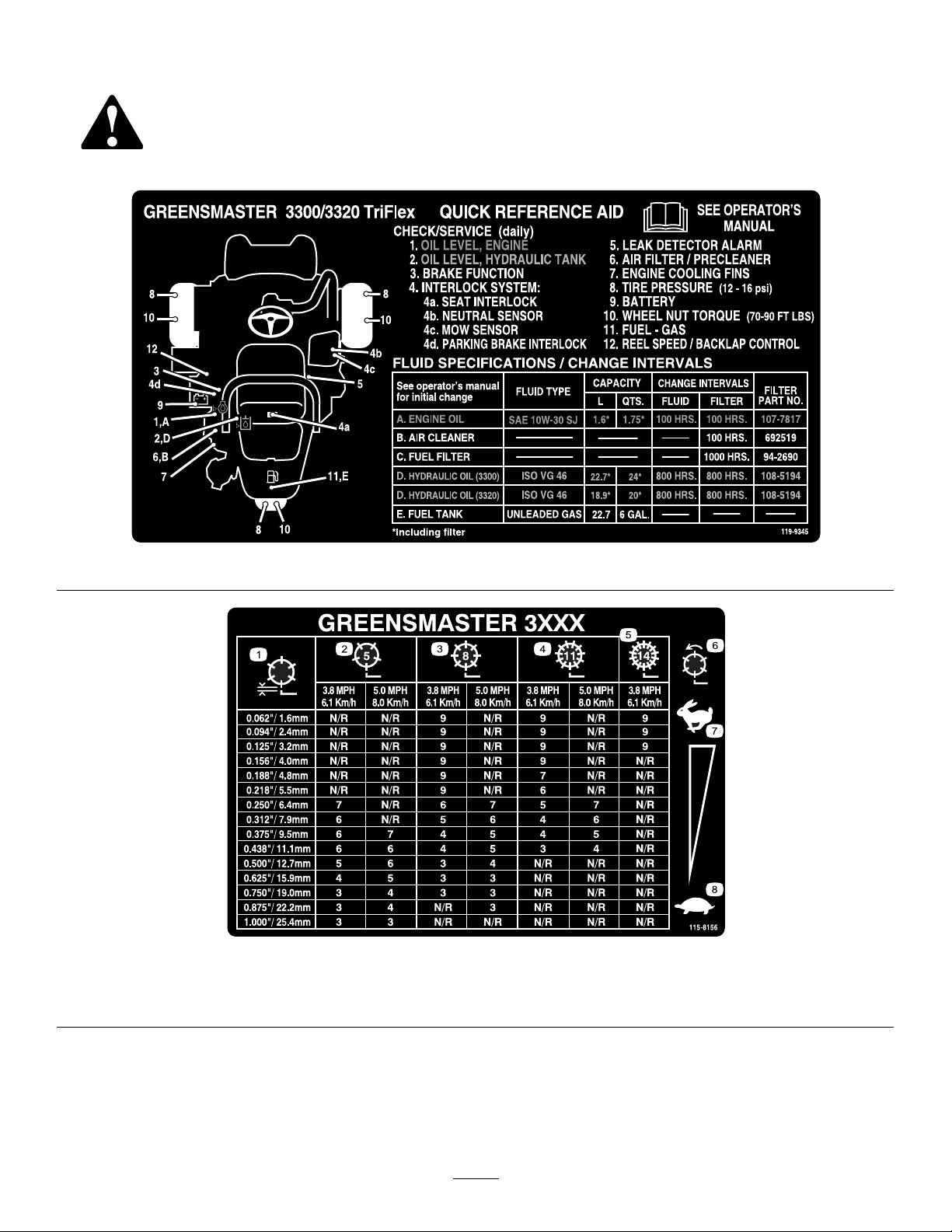
SafetyandInstructionalDecals
Safetydecalsandinstructionsareeasilyvisibletotheoperatorandarelocatednearanyareaofpotential
danger.Replaceanydecalthatisdamagedorlost.
119-9345
115-8156
1.Reelheight3.8Bladecuttingunit5.14Bladecuttingunit7.Fast
2.5Bladecuttingunit4.11Bladecuttingunit6.Reelspeed
8.Slow
8
Page 9
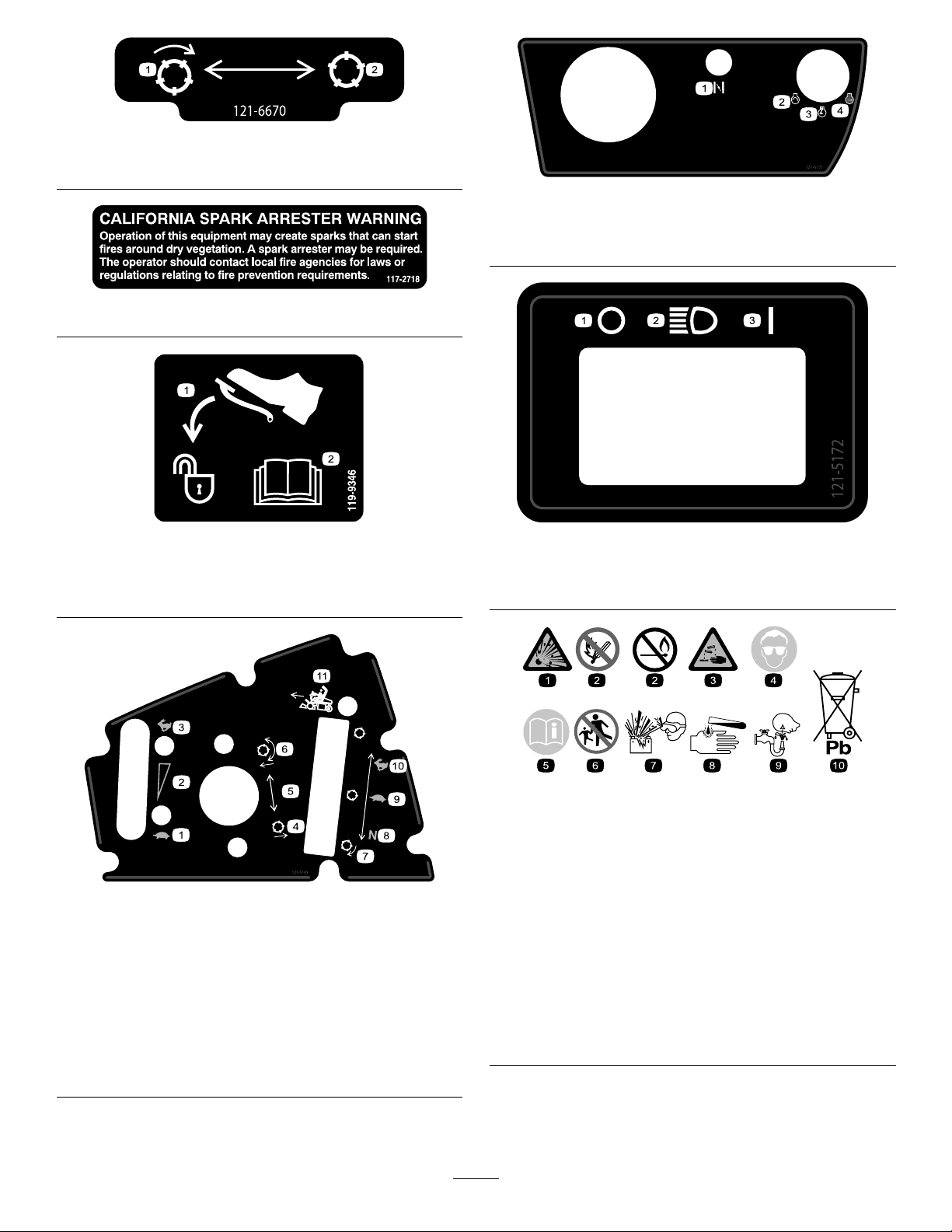
121–6670
1.Engagethereels.2.Disengagethereels.
121–5171
1.Presspedaltounlock
1.Choke
2.Engine—start4.Engine—stop
3.Enginerun
117–2718
119-9346
2.ReadtheOperator's
Manualformore
information.
1.Off3.On
2.Headlights
121–5172
1.Slow
2.Continuous
variable
setting
3.Fast6.Lower
4.Raisethe
reels
5.Reel
position
setting
and
engage
thereels
121–5169
7.Reel—backlapping 10.Fast—use
8.Neutral—use
for
backlapping
9.Slow—use
for
mowing
BatterySymbols
Someorallofthesesymbolsareonyourbattery
1.Explosionhazard
2.Nore,opename,or
smoking.
for
transport
11.Functional
control
lever
3.Causticliquid/chemical
burnhazard
4.Weareyeprotection9.Flusheyesimmediately
5.ReadtheOperator's
Manual.
6.Keepbystandersasafe
distancefromthebattery.
7.Weareyeprotection;
explosivegasescan
causeblindnessandother
injuries
8.Batteryacidcancause
blindnessorsevereburns.
withwaterandgetmedical
helpfast.
10.Containslead;donot
discard.
9
Page 10
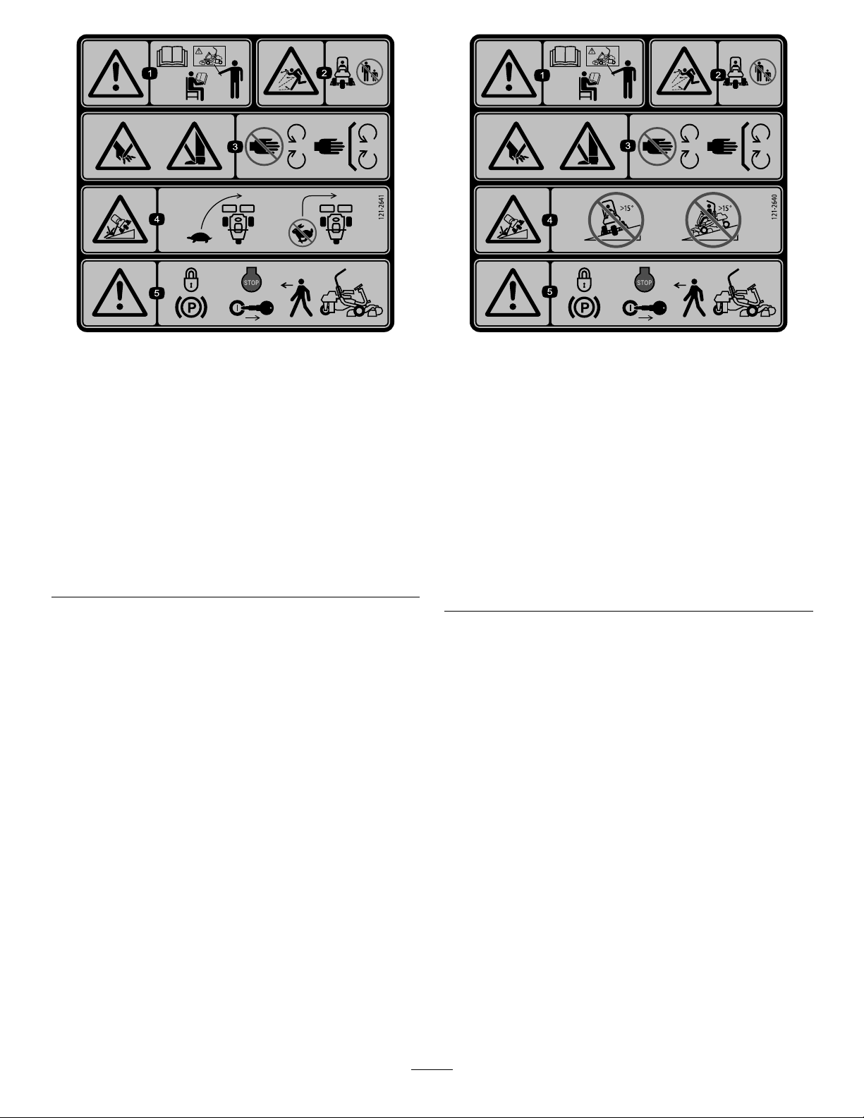
121–2641
121–2640
1.Warning—readthe
Operator’sManual,do
notoperatethismachine
unlessyouaretrained.
2.Thrownobject
hazard—keepbystanders
asafedistancefromthe
machine.
3.Cutting/dismemberment
hazardofhandorfoot,
mowerblade—stayaway
frommovingparts;keep
allguardsandshieldsin
place.
4.Tippinghazard—slow
machinebeforeturning,
donotturnathighspeeds.
5.Warning—locktheparking
brake,stoptheengine
andremovetheignition
keybeforeleavingthe
machine.
1.Warning—readthe
Operator’sManual,do
notoperatethismachine
unlessyouaretrained.
2.Thrownobject
hazard—keepbystanders
asafedistancefromthe
machine
3.Cutting/dismemberment
hazardofhandorfoot,
mowerblade—stayaway
frommovingparts;keep
allguardsandshieldsin
place.
4.Tippinghazard—donot
driveacrossslopesgreater
than15degreesordown
slopesgreaterthan15
degrees.
5.Warning—locktheparking
brake,stoptheengine
andremovetheignition
keybeforeleavingthe
machine.
10
Page 11

Setup
LooseParts
Usethechartbelowtoverifythatallpartshavebeenshipped.
ProcedureDescription
1
2
3
4
5
6
7
8
Rollbar1
Bolt(1/2x3-3/4inches)
Flange-nut(1/2inch)
Seat
Seatwiringharness
Steeringwheel
Locknut(1-1/2inches)
Washer1
Steeringwheelcap
Nopartsrequired
Nopartsrequired
Grassbaskethook
Flangebolts12
Gaugebar
Cuttingunit(model04613,04614,or
04615)
Cuttingunitupperweight
Hexheadscrews6
GrassBasket
Weightkit,119-7129(for2-wheeldrive
units)
Weightkit,120-5750(forunitswiththe
3-wheeldrivekitinstalled)
Qty.
Use
4
4
1
1
1
1
1
–
–
6
1
3
3
3
1
1
Installtherollbar.
Installtheseattothebase.
Installthesteeringwheel.
Activateandchargethebattery.
Installtheoptionaloilcooler.
Installthegrassbaskethooks.
Installthecuttingunits
Addrearweight.
9
Warningdecal121–26401
MediaandAdditionalParts
Description
Operator'sManual(machine)
EngineOperator'sManual(engine)
PartsCatalog
OperatorTrainingMaterials
Pre-deliveryInspectionSheet
Noiseratingcerticate
Certicateofcompliance
Ignitionkeys2
Qty.
InstallEUdecals,ifrequired.
Use
1
1
1
1
1
1
1
Readbeforeoperatingthemachine.
Saveforfuturepartsordering.
Viewbeforeoperatingthemachine.
Saveforfuturereference.
Starttheengine.
11
Page 12
1
g014601
1
2
3
g016317
1
2
3
4
5
2
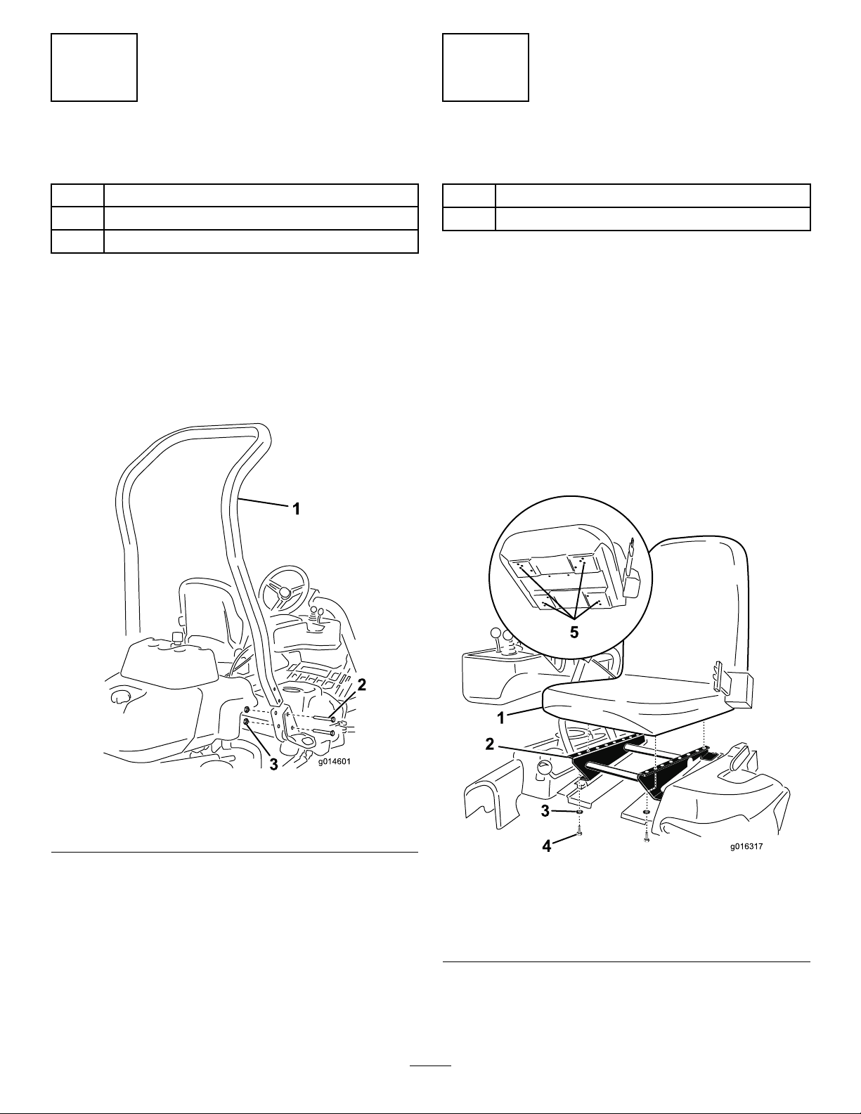
InstallingtheRollBar
Partsneededforthisprocedure:
1Rollbar
4
Bolt(1/2x3-3/4inches)
4
Flange-nut(1/2inch)
Procedure
1.Removethetopcratesupportfromthecrate.
2.Removetherollbarfromthecrate.
3.Installtherollbarintothepocketsoneachsideof
themachine,using4bolts(1/2x3-3/4inches)and4
ange-nuts(1/2inch)(Figure3)
InstallingtheSeat
Partsneededforthisprocedure:
1
Seat
1
Seatwiringharness
Procedure
Note:Mounttheseatinthefrontsetofmountingholesto
gainanadditional7.6cm(3inches)intheforwardadjustment,
orintherearmountingholesforanadditional7.6cm(3
inches)intherearwardadjustment.
1.Removeanddiscardthelagboltssecuringtheseat
slidesandcuttheshippingstraps.
2.Removethe4bolts(5/16x3/4inch)andwashers
fromtheshippingbracketanddiscardthebracket.
3.Securetheseattotheseatbasewith4boltsandwashers
removedpreviously(Figure4).
Figure3
1.Rollbar
2.Bolt(1/2x3-3/4inches)
4.Torquethefastenersto136to149N-m(100to110
ft-lb).
3.Flange-nut(1/2inch)
Figure4
1.Seat4.Bolt(5/16x3/4inch)
2.Seatbase
3.Washer
12
5.Installtheseatusingthese
holes.
Page 13
4.Locatetheopenconnectoronthemainwiringharness
totherightoftheseatandconnectittothewiring
harnessthatcamewiththeseat.
5.Routetheseatwiringharnessaroundtheseatslides,
ensuringthatitwillnotbepinchedwhentheseat
moves,andconnectittotheportonthebottomof
theseat.
4
ActivatingandChargingthe Battery
NoPartsRequired
3
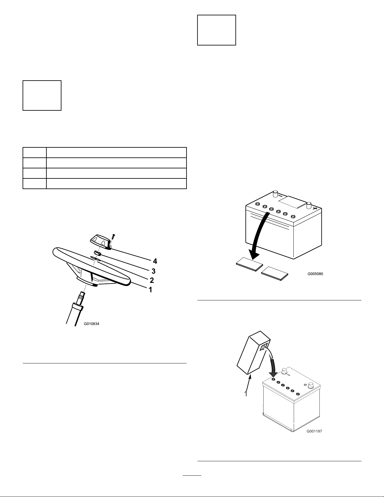
InstallingtheSteeringWheel
Partsneededforthisprocedure:
1
Steeringwheel
1
Locknut(1-1/2inches)
1Washer
1
Steeringwheelcap
Procedure
1.Slidethesteeringwheelontothesteeringshaft(Figure
5).
Procedure
Useonlyelectrolyte(1.265specicgravity)tollbattery
initially.
1.Removethefastenersandbatteryclampandliftout
thebattery.
Important:Donotaddelectrolytewhilethe
batteryisinthemachine.Y oucouldspillit,
causingcorrosion.
2.Cleanthetopofthebatteryandremovetheventcaps
(Figure6).
Figure5
1.Steeringwheel
2.Washer
2.Slidethewasherontothesteeringshaft(Figure5).
3.Securethesteeringwheeltotheshaftwithajamnut
andtightenitto27to35N-m(20to26ft-lb)(Figure5).
4.Installthecaptothesteeringwheelandsecureitwitha
screw(Figure5).
3.Jamnut
4.Cap
Figure6
3.Carefullylleachcellwithelectrolyteuntiltheplates
arecoveredwithabout6mm(1/4inch)ofuid(Figure
7).
Figure7
1.Electrolyte
13
Page 14

4.Allowapproximately20to30minutesforthe
1 2
g016293
3
4
5
6
7
electrolytetosoakintotheplates.Fillasnecessaryto
bringtheelectrolytetowithinabout6mm(1/4inch)
ofthebottomofthellwell(Figure7).
WARNING
Chargingthebatteryproducesgassesthatcan
explode.
Neversmokenearthebatteryandkeepsparks
andamesawayfrombattery.
5.Connecta2to4ampbatterychargertothebattery
posts.Chargethebatteryfor2hoursat4ampsorfor
4hoursat2ampsuntilthespecicgravityis1.250or
higherandthetemperatureisatleast16°C(60°F)
withallcellsgassingfreely .
6.Whenthebatteryischarged,disconnectthecharger
fromtheelectricaloutletandbatteryposts.
Note:Afterthebatteryhasbeenactivated,add
onlydistilledwatertoreplacenormalloss,although
maintenance-freebatteriesshouldnotrequirewater
undernormaloperatingconditions.
7.Placethebatteryonthebatterytrayandsecureitwith
thebatteryclampandfastenersremovedpreviously
(Figure8).
Figure8
Gasolinemodelshown,yourmodelmayvary .
WARNING
CALIFORNIA
Proposition65Warning
Batteryposts,terminals,andrelated
accessoriescontainleadandleadcompounds,
chemicalsknowntotheStateofCalifornia
tocausecancerandreproductiveharm.
Washhandsafterhandling.
WARNING
Batteryterminalsormetaltoolscouldshort
againstmetaltractorcomponentscausing
sparks.Sparkscancausethebatterygassesto
explode,resultinginpersonalinjury.
•Whenremovingorinstallingthebattery,
donotallowthebatteryterminalstotouch
anymetalpartsofthetractor.
•Donotallowmetaltoolstoshortbetween
thebatteryterminalsandmetalpartsof
thetractor.
1.Batteryclamp
2.Battery6.Batteryclamphook
3.Positive(+)batterycable
4.Batteryclampwingnut
8.Installthepositivecable(red)tothepositive(+)
terminalandthenthenegativecable(black)tothe
negative(–)terminalofthebatteryandsecurethem
withtheboltsandnuts(Figure8).Slidetherubber
bootoverthepositiveterminaltopreventapossible
shortfromoccurring.
5.Negative(-)batterycable
7.Batterytray
WARNING
Incorrectbatterycableroutingcoulddamagethe
tractorandcablescausingsparks.Sparkscancause
thebatterygassestoexplode,resultinginpersonal
injury.
•Alwaysdisconnectthenegative(black)battery
cablebeforedisconnectingthepositive(red)
cable.
•Alwaysconnectthepositive(red)batterycable
beforeconnectingthenegative(black)cable.
WARNING
Failuretocorrectlyactivatethebatterymay
resultinbatterygassingand/orpremature
batteryfailure.
14
Page 15
5
g014596
1
2
2
7
InstallingtheOptionalOil
Cooler
NoPartsRequired
Procedure
Ifyouareoperatingthemachineinhotclimates,wherethe
ambienttemperatureisabove29°C(85°F),orusingitfor
heavy-dutyuse(mowingotherthangreens,suchasfairways
orverticutting),installaHydraulicOilCoolerKit,PartNo.
119-1691,tothemachine.
6
InstallingtheGrassBasket Hooks
Partsneededforthisprocedure:
6
Grassbaskethook
12Flangebolts
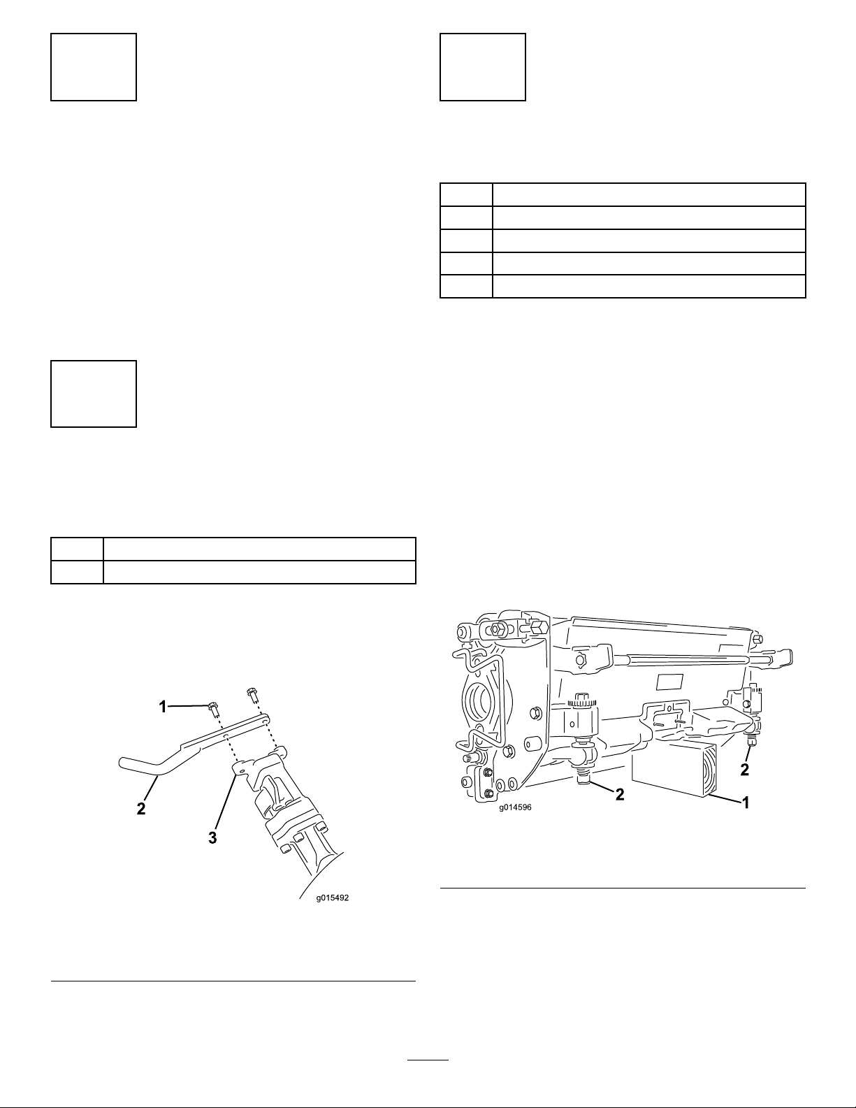
InstallingtheCuttingUnits
Partsneededforthisprocedure:
1
Gaugebar
3
Cuttingunit(model04613,04614,or04615)
3
Cuttingunitupperweight
6Hexheadscrews
3
GrassBasket
Procedure
Note:Whensharpening,settingtheheight-of-cut,or
performingothermaintenanceproceduresonthecutting
units,storethecuttingunitreelmotorsinthestoragelocation
onthefrontofthesuspensionarmstopreventdamageto
them.
Important:Donotraisethesuspensiontothetransport
positionwhenthereelmotorsareintheholdersinthe
machineframe.Damagetothemotorsorhosescould
result.
Important:Wheneverthecuttingunithastobetipped
toexposebedknife/reel,propuprearofcuttingunitto
makesurenutsonbackendofbedbaradjustingscrews
arenotrestingonworksurface(Figure10).
Procedure
Installthe6grassbaskethooksontotheendsofthe
suspensionarmbarsusing12angebolts(Figure9).
Figure9
1.Flangebolt
2.Grassbaskethook
3.Suspensionarmbar
Figure10
1.Prop(notprovided)2.Bedknifeadjustingscrew
nut(2)
Note:Allcuttingunitsareshippedwiththecounterweight
mountedtotherightendandthemotormountanddrive
couplermountedtotheleftendofthecuttingunit.
1.Disconnectthecuttingunitpowerdisconnectcouplers;
refertoCuttingUnitPowerDisconnect(page25).
15
Page 16

CAUTION
1
2
g016294
3
g014602
1
2
g014609
1
2
3
CAUTION
Ifyoudonotdisconnectthepowertothe
cuttingunits,someonecouldaccidentally
startthecuttingunit,causingseriousinjury
tohandsandfeet.
Alwaysseparatethecuttingunitpower
disconnectcouplersbeforeworkingonthe
cuttingunits.
2.Applygreasetotheinsidediameterofthedrivecoupler.
3.Thecuttingunitisshippedwithoutafrontroller.
Obtainaroller(ModelNo.04625,04626or04627)
fromyourlocalToroDistributor.Installtheroller
usingtheloosepartssuppliedwiththecuttingunitand
installationinstructionsincludedwiththeroller.
4.Removethe2boltssecuringtheweighttothesideof
thecuttingunit(Figure11).
Thefootrestcanpinchngersifitfallsinto
theclosedposition.
Keepyourngersclearoftheareawherethe
footrestseatswhileitisopen.
Figure12
1.Footrest—closed2.Footrest—open
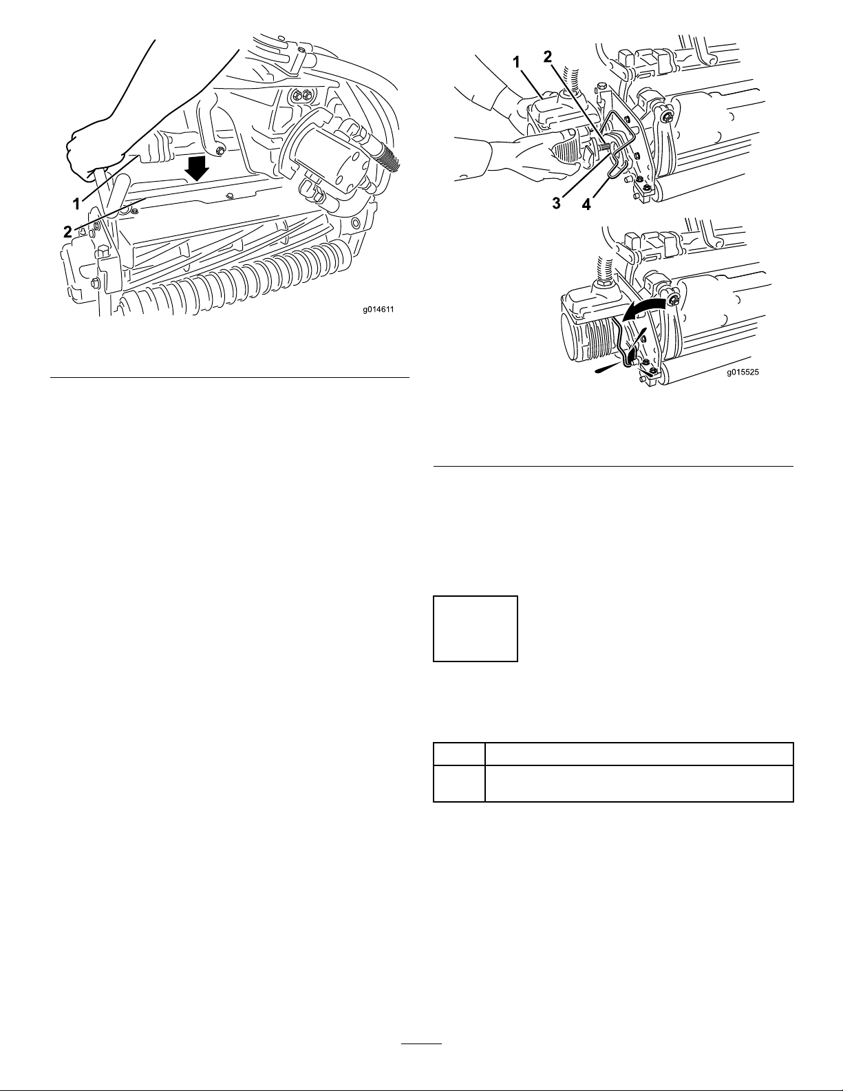
8.Positionthecuttingunitunderthesuspensionarm.
9.Withthelatchesonthesuspension-armbarpointing
up(i.e.,open)(Figure13),pushthesuspensionarm
downsothatthebartsoverthebaracrossthetopof
thecuttingunit(Figure14).
Figure11
1.Cuttinguntilweight(ip
over)
2.Upperweight
3.Hexheadscrews
5.Rotatetheweight180degreessothattheopenscrew
holesthatwereontheundersideoftheweightarenow
ontop.Installtheweighttothecuttingunitusingthe
boltsremovedpreviously.
6.Installanupperweighttothecuttingunitweightusing
2hexheadscrews(Figure11).
7.Ifinstallingthecentercuttingunit,liftuponthefoot
restandswingitup,allowingaccesstothecenter
cuttingunitposition(Figure12).
Figure13
1.Latch—closedposition3.Latch—openposition
2.Suspension-armbar
16
Page 17
g01461 1
1
2
Figure14
1.Suspension-armbar2.Cutting-unitbar
10.Closethelatchesdownandaroundthecutting-unitbar
andlocktheminplace(Figure13).
Note:A“click”canbeheardandfeltwhenthelatches
areproperlylockedinplace.
11.Coatthesplineshaftofthecuttingunitmotorwith
cleangrease(Figure15).
12.Insertthemotorintotheleftsideofthecuttingunit
(asviewedfromtheoperator'sposition)andpullthe
motorretainingbaronthecuttingunittowardthe
motoruntilyouhearanaudible“click”frombothsides
ofthemotor(Figure15).
Figure15
1.Reelmotor
2.Splineshaft
13.Mountagrassbasketontothebaskethooksonthe
suspensionarm.
14.Repeatthisprocedurefortheothercuttingunits.
15.Connectthecuttingunitpowerdisconnectcouplers;
refertoCuttingUnitPowerDisconnect(page25).
3.Cavity
4.Motorretainingbar
8
AddingRearWeight
Partsneededforthisprocedure:
1
Weightkit,119-7129(for2-wheeldriveunits)
Weightkit,120-5750(forunitswiththe3-wheeldrive
1
kitinstalled)
Procedure
ThisunitcomplieswiththeANSIB71.4-2004andEN836
Standardswhenequippedwithweightkit119-7129(2-wheel
driveunits)or120-5750(3-wheeldriveunits).
17
Page 18

9
g014674
1
2
3
4
5
6
7
8
InstallingEUDecals
Partsneededforthisprocedure:
1Warningdecal121–2640
Procedure
IfthismachinewillbeusedintheEU,afxthewarningdecal
121–2640overwarningdecal121–2641.
ProductOverview
Figure16
1.Engine
2.Rollbar6.Tractionpedal
3.Controlpanel
4.Seat8.Cuttingunits
5.Steeringwheel
7.Footrest
Controls
TractionPedal
Thetractionpedal(Figure17)hasthreefunctions:tomake
themachinemoveforward,tomoveitbackward,andtostop
themachine.Pressthetopofthepedaltomoveforward
andthebottomofthepedaltomovebackwardortoassist
instoppingwhenmovingforward.Also,allowthepedal
tomovetotheNeutralpositiontostopthemachine.For
operatorcomfort,donotresttheheelofyourfootonreverse
whenoperatingforward(Figure18).
18
Page 19

g014603
1
2
3
Figure17
G017945
1
3
2
4
5
6
1.Tractionpedal—forward3.Steeringarmlockingpedal
2.Tactionpedal—reverse
Figure19
1.Ignitionswitch
2.Choke
3.Functionalcontrollever
4.Raise/LowerMowControl
5.Throttlecontrol
6.InfoCenter
Choke
Tostartacoldengine,closethecarburetorchokebypulling
thechokecontrol(Figure19)outtotheClosedposition.
Aftertheenginestarts,regulatethechoketokeeptheengine
runningsmoothly.Assoonaspossible,openthechokeby
pushingitintotheOpenposition.Awarmenginerequires
littleornochoking.
Figure18
SteeringArmLockingPedal
Pressthepedal(Figure17)andraiseorlowerthesteering
armforoperatorcomfort,then,releasethepedaltolockthe
arminplace.
Note:Movethesteeringarmfullyforwardbeforelifting
theseat.
ThrottleControl
Thethrottlecontrol(Figure19)givestheoperatortheability
tocontrolthespeedoftheengine.Movingthethrottle
controltowardtheFastpositionincreasestheenginerpm;
movingthethrottlecontroltowardSlowwilldecreasethe
enginerpm.Groundspeedsareasfollows:
•3.2to8km/h(2to5mph)forwardmowingspeed
•16km/h(10mph)maximumtransportspeed
•4.0km/h(2.5mph)reversespeed
Note:Theenginecannotbestoppedbytheuseofthe
throttlecontrol.
Raise/LowerMowControl
Movingthecontrol(Figure19)forwardduringoperation
lowersthecuttingunitsandstartsthereels.Pullbackonthe
controltostopthereelsandraisethecuttingunits.During
operationthereelscanbestoppedbypullingbackonthe
controlmomentarilyandreleasingit.Thisfeatureisknownas
Tap-offandisadjustableintheInfoCenter.Restartthereels
bymovingthecontrolforward.
FunctionalControlLever
Thefunctionalcontrollever(Figure19)providestwotraction
selectionsplusaNeutralposition.Itispermissibletoshift
frommowtotransportortransporttomow(nottoneutral)
whilethemachineisinmotion.Nodamagewillresult.
•RearPosition—neutralandbacklapping
•MiddlePosition—usedformowingoperation
•FrontPosition—usedfortransportoperation
19
Page 20
IgnitionSwitch
G017943
2
2
7.5
7.5
7.5
7.5
7.5
7.5
10
10
15
15
C2
C2
1
2
1
G017973
2
3
4
5
6
7
8
9
TORO
13.2
10,000.0
STOP
n/min
52.2V
10,000.0
n/min
52.2V
1200
1600
n/min
G017974
2
1
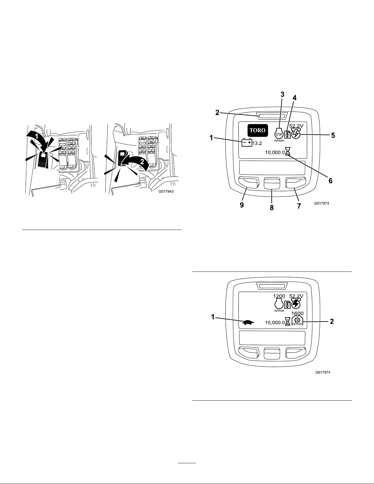
UsingtheInfoCenterLCDDisplay
Insertthekeyintotheswitch(Figure19)andturnitclockwise
asfaraspossibletotheStartpositiontostarttheengine.
Releasethekeyassoonastheenginestarts;thekeywillmove
totheOnposition.TurnthekeycounterclockwisetotheOff
positiontostoptheengine.
BacklapSwitch
Thebacklapswitchislocatedundertheplasticcoverto
theleftoftheseat.Usethebacklapswitch(Figure20)in
conjunctionwiththeraise/lowermowcontrolleverandthe
reelspeedcontrolforbacklappingthereels.
Figure20
TheInfoCenterLCDdisplayshowsinformationaboutyour
machinesuchasthegeneratorstatus,thespeed,andvarious
diagnosticsandotherinformationaboutthemachineandthe
batterypack.Figure21andFigure22illustratethesplash
screenandmaininformationscreenoftheInfoCenter.You
canswitchbetweenthesplashscreenandmaininformation
screenatanytimebypressinganyoftheInfoCenterbuttons
andthenselectingtheappropriatedirectionalarrow.
1.Backlapswitch—backlap
position
2.Backlapswitch—mow
position
Figure21
1.Batteryvoltage6.Hourmeter
2.Powerlight/faultindicator
3.EngineRPM/status
4.Faultlog
7.Rightbutton
8.Downbutton
9.Menuaccess/backbutton
5.Generatorvoltage/status
Figure22
1.Functionalcontrolstatus
2.PTOspeed
•Enginerpm/status—indicatestheenginerpm.
•Faultlog—indicatesthatthereisacurrentfaultlogto
review.
•Generatorvoltage/status—indicatesthegenerator
voltage.
20
Page 21

•Hourmeter—indicatesthetotalhoursthemachinehas
operated.Itstartstofunctionwheneverthekeyswitch
isrotatedtoOn.
•PTOspeed—indicatesthePTOspeed.
•Glowplug—indicatesthattheglowplugisactive.
•Batteryvoltage—indicatesthebatterypotentialinVolts.
•Coolanttemperature—indicatestheenginecoolant
temperatureineither°Cor°F .
•Functionalcontrolstatus—transportmodeisindicated
byarabbitandmowmodeisindicatedbyaturtle.
•Engineoilpressurelight—thisiconappearsiftheengine
oilpressuredropsbelowasafelevel.
•Menuaccess/backbutton—pressthisbuttontoaccess
theInfoCentermenus.Youcanuseittobackoutofany
menuyouarecurrentlyusing.
•Downbutton—usethisbuttontoscrolldownmenus.
•Rightbutton—usethisbuttontoopenamenuwherea
rightarrowindicatesadditionalcontent.
Note:Thepurposeofeachbuttonmaychangedepending
onwhatisrequiredatthetime.Eachbuttonwillbelabeled
withanicondisplayingitscurrentfunction.
21
Page 22

UsingtheMenus
ToaccesstheInfoCentermenusystem,pressthemenuaccess
buttonwhileatthemainscreen.Thiswillbringyoutothe
mainmenu.Refertothefollowingtablesforasynopsisof
theoptionsavailablefromthemenus:
MainMenu
MenuItemDescription
FaultsTheFaultsmenucontains
ServiceTheServicemenucontains
DiagnosticsTheDiagnosticsmenu
SettingsTheSettingsmenuallows
AboutTheAboutmenuliststhe
Service
MenuItemDescription
Hours
CountsListsthenumberofpreheats
Diagnostics
MenuItemDescription
EngineRun
alistoftherecentmachine
faults.RefertotheService
ManualoryourAuthorized
ToroDistributorformore
informationontheFaults
menuandtheinformation
containedthere.
informationonthemachine
suchashoursofuseandother
similarnumbers.
listsvariousstatesthatthe
machinecurrentlyhas.You
canusethistotroubleshoot
certainissuesasitwillquickly
tellyouwhichmachine
controlsareonandwhichare
off.
youtocustomizeandmodify
congurationvariablesonthe
InfoCenterdisplay.
modelnumber,serialnumber,
andsoftwareversionofyour
machine.
Liststhetotalnumberofhours
thatthemachine,engine,
reels,backlap,andfanhave
beenon,aswellasthe
numberofhoursthemachine
hasbeentransportedand
overheated.
andstartsthemachinehas
experienced.
Indicatesifthefollowingitems
areactive:Keystart,keyrun,
joysticklower,joystickraise,
neutral,seatorparkingbrake,
OKrun,andRTRorETR.
S1–S4Controlstheraisingand
ReelsEnable
Settings
MenuItemDescription
Units
Language
LCDBacklightControlsthebrightnessofthe
LCDContrastControlsthecontrastofthe
ProtectedMenus
ProtectionSettingsControlstheprotectedmenus.
ResetDefaultsResetstheInfoCenterto
RaiseDelay
LowerDelay
TapoffDelayControlsthetap-offdelay.
ReelSpeedControlsthereelspeed.
Backlaprpm
About
MenuItemDescription
Model
SNListstheserialnumberofthe
TEC5001Liststhesoftwarerevisionof
InfoCenterListsthesoftwarerevisionof
CU1Liststhesoftwarerevisionof
CU2Liststhesoftwarerevisionof
CU3Listthesoftwarerevisionof
GeneratorListstheserialnumberofthe
CANBus
loweringofthesolenoids.
IndicatesiftheeReelis
enabled.
Controlstheunitsusedonthe
InfoCenter.Themenuchoices
areEnglishorMetric.
Controlsthelanguageused
ontheInfoCenter.
LCDdisplay.
LCDdisplay.
Allowsthedistributor/engineer
toaccessprotectedmenusby
inputtingapasscode.
defaultsettings.
Controlstheraisedelaytime
forthecentercuttingunit.
Controlsthelowerdelayfor
thecentercuttingunit.
Controlsthebacklaprpm
speed.
Liststhemodelnumberofthe
machine.
machine.
themastercontroller .
theInfoCenter.
therstcuttingunit.
thesecondcuttingunit.
thethirdcuttingunit.
generator.
Liststhemachine
communicationbusstatus.
22
Page 23

CenterCuttingUnitRaise/LowerDelay
g014736
Theraiseandlowerdelaytimeforthecentercuttingmaybe
adjustedindependentlywiththeInfoCenter.Eachsetting
maybeadjustedfrom1to9accordingtothetablebelow .
Thefactorydefaultsettingis6(375ms)andisoptimizedfor
a3.8mphmowspeed.
3.Usingtheappropriategraph(SeeFigure23)for5,8,
11,or14bladecuttingunits,determinetheproperreel
speedsetting.
IncrementNumber
10.100
20.150
30.200
40.250
5
60.375
7
80.600
90.750
100.925
DelayTime(Seconds)
0.300
0.475
Tap-offDelay
Thetap-offdelayfeatureallowsthecuttingunitstoturnoff
withoutraising,andmaybeadjustedwiththeInfoCenter.The
delaysettingrepresentsthemaximumtimefortheraise/lower
joysticktoremainintheraisepositiontoactivatethisfeature.
Thefactorydefaultsettingis1whichdisablesthisfeature.
IncrementNumber
1
20.050
30.100
40.150
5
60.250
7
80.350
90.400
100.450
DelayTime(Seconds)
Off
0.200
0.300
Figure23
4.Tosetthereelspeed,ontheInfoCenteropentheMain
MenuandscrolldowntoSettings.
5.IntheSettingsmenuscrolldowntoReelSpeedand
usethe±buttontosetthereelspeedtothedesired
number.
MachineCongurationPasscode
Thereare5operatingcongurationsettingsthatare
adjustablewithinthesettingmenuoftheInfoCenter:Raise
andlowerdelay,tap-offdelay,reelspeed,andbacklapspeed.
Thesesettingcanbeprotectedbyauserdenedpasscodeby
openingtheMainmenuandscrollingdowntotheSettings
menu.FindProtectSettingsandselectOn.
WhenprotectsettingOnisselectedtheuserisprompted
toenterafourdigitpasscode.Afterthepasscodeisset,the
keyswitchmustbeturnedoffandbackontoenableand
savethisfeature.Afterenablingtheprotectsettingsoption,
thecongurationsettingsarehiddenuntiltheuserdened
passcodeisentered.
Note:Iftheuserdenedpasscodeisforgotten,atemporary
passcodecanbeobtainedthroughyourauthorizedT oro
distributor.
SettingtheReelSpeed
Toachieveaconsistent,highquality–of–cutandauniform
aftercutappearance,itisimportantthatthereelspeedcontrol
becorrectlyset.
Adjustthereelspeedcontrolasfollows:
1.Selecttheheight-of-cutatwhichthecuttingunitsare
set.
2.Choosethedesiredgroundspeedbestsuitedfor
conditions.
DiagnosingtheFaultLogIndicator
Thefaultlogindicatoriconappearsonthemainscreeninthe
eventofafaultinthemachine(Figure21).Whenthisiconis
presentthereisanewlogentryintheFaultsmenuthatyou
oryourdistributorcanusetoidentifytheproblem.
Foralistoffaults,refertoyourAuthorizedDistributoror
theServiceManual.
23
Page 24

ParkingBrakeLever
g01461 0
g014628
1
g01462 6
1
Pulluponthebrakelever(Figure24)tosettheparkingbrake.
Disengageitbypushingitforwardanddown.Settheparking
brakeanytimeyouleavethemachine.Aniconwillappearon
theInfoCenterscreenwhentheparkingbrakeisset.
Figure25
1.Seatadjustinglever
Figure24
SeatAdjustingLever
Theseatadjustingleverislocatedonthefront,rightcorner
oftheseat(Figure25),allowingyoutoadjusttheseatfore
andaft.Pushthelevertotheleft(towardsthecenter),to
releasethelockandslidetheseat.
Note:Ifyouneedadditionaladjustmentontheseat,youcan
removethefourboltssecuringtheseattothebaseandmove
theseattothesecondsetofmountingholesprovided.
Note:Beforeliftingtheseat,slideittothefurthestback
positionandmovethesteeringarmfullyforward.
FuelShutoffValve
Closethefuelshutoffvalve(Figure26),behindtheseatand
underthefueltank,whenstoringortransportingthemachine
onatruckortrailer.
1.Fuelshutoff(underthefueltank)
24
Figure26
Page 25
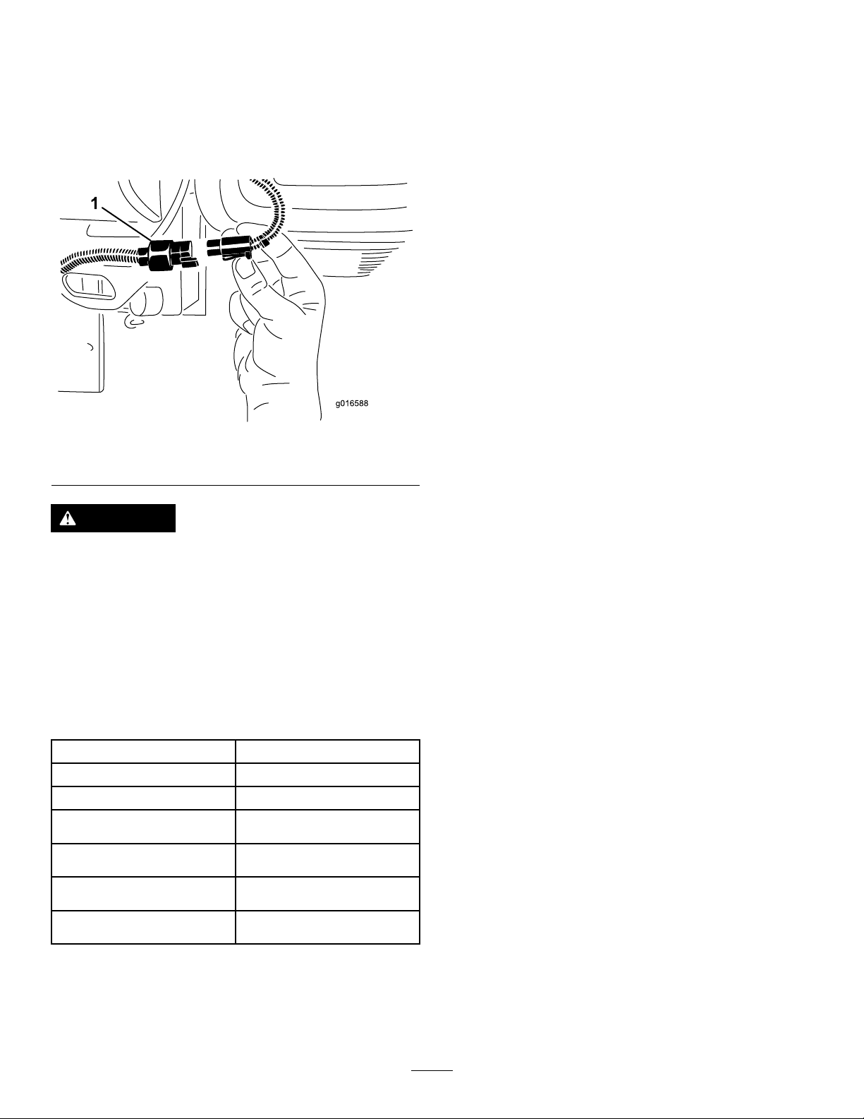
CuttingUnitPowerDisconnect
Beforeinstalling,removing,orworkingonthecutting
units,disconnectthecuttingunitsfromthepowersupply
byseparatingthecuttingunitpowerdisconnectconnector
(Figure27),locatedatthebaseoftherolloverbarontheleft
sideofthemachine.Plugtheconnectorstogetherbefore
operatingthemachine.
Figure27
itscapabilities.ContactyourAuthorizedServiceDealeror
Distributororgotowww .Toro.comforalistofallapproved
attachmentsandaccessories.
1.Cuttingunitpowerdisconnectconnector
CAUTION
Ifyoudonotdisconnectthepowertothecutting
units,someonecouldaccidentallystartthecutting
unit,causingseriousinjurytohandsandfeet.
Alwaysseparatethecuttingunitpowerdisconnect
connectorsbeforeworkingonthecuttingunits.
Specications
Note:Specicationsanddesignaresubjecttochange
withoutnotice.
Widthofcut151cm(59.5inches)
Wheeltread
Wheelbase
Overalllength(w/baskets)249cm(98.0inches)
Overallwidth179cm(70.62inches)
128cm(50.5inches)
119cm(46.9inches)
Overallheight205cm(80.83inches)
Weight
Refertothemachineserial
tag(Figure1).
Attachments/Accessories
AselectionofToroapprovedattachmentsandaccessoriesis
availableforusewiththemachinetoenhanceandexpand
25
Page 26

Operation
1
2
g016292
Important:Checktheoillevelevery8operating
hoursordaily .
Note:Determinetheleftandrightsidesofthemachine
fromthenormaloperatingposition.
ThinkSafetyFirst
Pleasecarefullyreadallofthesafetyinstructionsandsymbols
inthesafetysection.Knowingthisinformationcouldhelp
youorbystandersavoidinjury.
Theuseofprotectiveequipment,suchasbutnotlimitedto,
foreyes,ears,feet,andheadisrecommended.
CheckingtheEngineOil
Theengineisshippedwith1.65liters(1-3/4quarts)(w/lter)
ofoilinthecrankcase;however,theoillevelmustbechecked
beforeandaftertheengineisrststarted.
Theengineusesanyhigh-qualitydetergentoilhavingthe
AmericanPetroleumInstitute(API)serviceclassicationof
SG,SH,orSJorhigher.Therecommendedviscosity(weight)
isSAE30.
1.Positionthemachineonalevelsurface.
2.Unscrewthedipstickandwipeitwithacleanrag.
Screwthedipstickintothetubeandmakesureitis
seatedfully(Figure28).
5.Installthellercapanddipstickrmlyinplace.
FillingtheFuelTank
•Forbestresults,useonlyclean,fresh(lessthan30days
old),unleadedgasolinewithanoctaneratingof87or
higher((R+M)/2ratingmethod).
•Ethanol:Gasolinewithupto10%ethanol(gasohol)
or15%MTBE(methyltertiarybutylether)byvolume
isacceptable.EthanolandMTBEarenotthesame.
Gasolinewith15%ethanol(E15)byvolumeisnot
approvedforuse.Neverusegasolinethatcontainsmore
than10%ethanolbyvolume,suchasE15(contains15%
ethanol),E20(contains20%ethanol),orE85(contains
85%ethanol).Usingunapprovedgasolinemaycause
performanceproblemsand/orenginedamagewhichmay
notbecoveredunderwarranty.
•Donotusegasolinecontainingmethanol.
•Donotstorefueleitherinthefueltankorfuelcontainers
overthewinterunlessafuelstabilizerisused.
•Donotaddoiltogasoline.
DANGER
Incertainconditions,gasolineisextremely
ammableandhighlyexplosive.Areorexplosion
fromgasolinecanburnyouandothersandcan
damageproperty.
1.Dipstick2.Fillercap
3.Unscrewthedipstickoutofthetubeandcheckthe
oillevel.
4.Iftheoillevelislow,removethellercapfromthe
valvecoverandpouroilintotheopeninginthevalve
coveruntiltheoillevelisuptotheFullmarkonthe
dipstick.Addtheoilslowlyandchecktheleveloften
duringthisprocess.Donotoverll.
Figure28
•Fillthefueltankoutdoors,inanopenarea,
whentheengineiscold.Wipeupanygasoline
thatspills.
•Neverllthefueltankinsideanenclosedtrailer.
•Donotllthefueltankcompletelyfull.Add
gasolinetothefueltankuntilthelevelis1inch
(25mm)belowthebottomofthellerneck.
Thisemptyspaceinthetankallowsgasolineto
expand.
•Neversmokewhenhandlinggasoline,andstay
awayfromanopenameorwheregasoline
fumesmaybeignitedbyaspark.
•Storegasolineinanapprovedcontainerand
keepitoutofthereachofchildren.Neverbuy
morethana30-daysupplyofgasoline.
•Donotoperatewithoutentireexhaustsystemin
placeandinproperworkingcondition.
26
Page 27
DANGER
CheckingtheHydraulicFluid
Incertainconditionsduringfueling,static
electricitycanbereleasedcausingasparkwhich
canignitethegasolinevapors.Areorexplosion
fromgasolinecanburnyouandothersandcan
damageproperty.
•Alwaysplacegasolinecontainersontheground
awayfromyourvehiclebeforelling.
•Donotllgasolinecontainersinsideavehicleor
onatruckortrailerbedbecauseinteriorcarpets
orplastictruckbedlinersmayinsulatethe
containerandslowthelossofanystaticcharge.
•Whenpractical,removegas-poweredequipment
fromthetruckortrailerandrefueltheequipment
withitswheelsontheground.
•Ifthisisnotpossible,thenrefuelsuch
equipmentonatruckortrailerfromaportable
container,ratherthanfromagasolinedispenser
nozzle.
•Ifagasolinedispensernozzlemustbeused,
keepthenozzleincontactwiththerimofthe
fueltankorcontaineropeningatalltimesuntil
fuelingiscomplete.
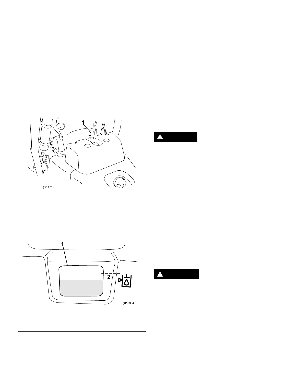
1.Cleanaroundthefueltankcapandremoveit(Figure
29).
Level
Thehydraulicuidreservoirislledatthefactorywith
approximately18.9L(5USgallons)ofhighqualityhydraulic
uid.Beforeoperatingthemachineeachday,checklevelof
thehydraulicuidinthewhiteplasticwindowonthefrontof
thehydraulicuidreservoir(behindtheseatontheleftside).
Theuidshouldbebetweenthelinesinthewindow;ifnot,
addanappropriateuidasdescribedinthefollowingsections:
Therecommendedreplacementuidisasfollows:
ToroPremiumAllSeasonHydraulicFluid(Availablein5
gallonpailsor55gallondrums.SeepartscatalogorToro
distributorforpartnumbers.)
Alternateuids:IftheTorouidisnotavailable,otheruids
maybeusedprovidedtheymeetallthefollowingmaterial
propertiesandindustryspecications.W edonotrecommend
theuseofsyntheticuid.Consultwithyourlubricant
distributortoidentifyasatisfactoryproduct
Note:Torowillnotassumeresponsibilityfordamage
causedbyimpropersubstitutions,souseonlyproducts
fromreputablemanufacturerswhowillstandbehindtheir
recommendation.
HighViscosityIndex/LowPourPointAnti-wearHydraulic
Fluid,ISOVG46
MaterialProperties:
Viscosity,ASTMD445cSt@40°C44to48
ViscosityIndexASTM
D2270
PourPoint,ASTMD97-34°Fto-49°F
IndustrySpecications:
VickersI-286-S(QualityLevel),VickersM-2950-S
(QualityLevel),DenisonHF-0,Vickers35VQ(Eaton
ATS373-C)
cSt@100°C7.9to8.5
140to160
Figure29
1.Fueltankcap
2.Addunleadedregulargasolinetothefueltankuntilthe
levelis25mm(1inch)belowthebottomoftheller
neck.
Thisspaceinthetankallowsgasolinetoexpand.Do
notllthefueltankcompletelyfull.
Note:Thefueltankcapacityis22.7L(6USgallons).
3.Installthefueltankcapsecurely.Wipeupanygasoline
thatmayhavespilled.
Important:TheISOVG46Multigradeuidhasbeen
foundtoofferoptimalperformanceinawiderangeof
temperatureconditions.Foroperationinconsistently
highambienttemperatures,18°C(65°F)to49°C
(120°F),ISOVG68hydraulicuidmayofferimproved
performance.
PremiumBiodegradableHydraulicFluid-MobilEAL
EnviroSyn46H
Important:MobilEALEnviroSyn46Histheonly
syntheticbiodegradableuidapprovedbyT oro.This
uidiscompatiblewiththeelastomersusedinToro
hydraulicsystemsandissuitableforawide-range
oftemperatureconditions.Thisuidiscompatible
withconventionalmineraloils,butformaximum
biodegradabilityandperformancethehydraulicsystem
shouldbethoroughlyushedofconventionaluid.The
oilisavailablein19L(5gallon)containersor55gallon
drumsfromyourMobilDistributor.
Note:Manyhydraulicuidsarealmostcolorless,makingit
difculttospotleaks.Areddyeadditiveforthehydraulic
27
Page 28
systemoilisavailablein20ml(2/3oz)bottles.Onebottle
g014719
1
1
2
g016334
issufcientfor15-22L(4-6gallons)ofhydraulicoil.Order
partno.44-2500fromyourauthorizedTorodistributor.This
reddyeisnotrecommendedforusewithbiodegradable
uids.Usefoodcoloring .
Important:Regardlessofthehydraulicuidtypeused,
anymachineusedforoffgreenapplications,verticutting
orusedduringambienttemperaturesabove29°C(85°F)
shouldhaveOilCoolerKitinstalled;referto5Installing
theOptionalOilCooler(page14).
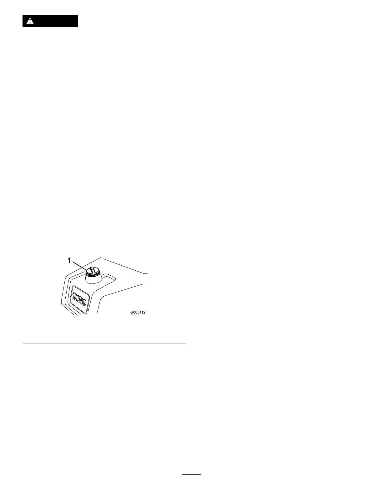
FillingtheHydraulicTank
1.Positionthemachineonalevelsurface.Makesurethe
machinehascooleddownsotheoiliscold.
2.Removethecapfromthereservoir(Figure30).
4.Installthereservoircap.Wipeupanyuidthatmay
havespilled.
Important:Checklevelofhydraulicuidbefore
engineisrststartedanddailythereafter.
CheckingtheReel-to-Bedknife Contact
Eachdaybeforeoperatingthemachine,checkthe
reel-to-bedknifecontact,regardlessifthequalityofcuthad
previouslybeenacceptable.Theremustbelightcontact
acrossthefulllengthofthereelandbedknife;referto
AdjustingtheReeltoBedknifeintheCuttingUnitOperator’s
Manual.
Beforecheckingthereels,disconnectthecuttingunitpower
disconnectcouplers;refertoCuttingUnitPowerDisconnect
(page25).Connectthemwhennished.
CAUTION
Ifyoudonotdisconnectthepowertothecutting
units,someonecouldaccidentallystartthecutting
unit,causingseriousinjurytohandsandfeet.
Figure30
1.Hydraulictankcap
3.Slowlyllthereservoirwiththeappropriatehydraulic
uiduntilthelevelisatorwithin6mm(1/4inch)of
thearrowinthesymbolnexttothewhitewindowin
thefrontofthereservoir(Figure31).Donotoverll.
Figure31
1.Whitewindowonthefront
ofthehydraulicreservoir
2.Filltowithinthisarea.
Alwaysseparatethecuttingunitpowerdisconnect
couplersbeforeworkingonthecuttingunits.
CheckingtheTirePressure
Thetiresareover-inatedatthefactoryforshipping
purposes.Reducethepressuretotheproperlevelsbefore
startingtheunit.
Varythetirepressureforall3wheels,dependinguponyour
turfconditions,fromaminimumof83toamaximumof110
kPa(12psito16psi).
CheckingtheTorqueofthe WheelNuts
WARNING
Failuretomaintainpropertorqueofthewheelnuts
couldresultinpersonalinjury.
Torquethewheelnutsto95to122N-m(70to90
ft-lb)after1-4hoursofoperationandagainafter
10hoursofoperation.T orqueevery200hours
thereafter.
Important:Topreventsystemcontamination,
cleanthetopofthehydraulicuidcontainers
beforepuncturing.Ensurethepourspoutand
funnelareclean.
Breaking-intheMachine
RefertotheEngineManualsuppliedwiththemachineforoil
changeandmaintenanceproceduresrecommendedduring
thebreak-inperiod.
28
Page 29

Only8hoursofmowingoperationisrequiredforthebreak-in
period.
ToroDistributorforassistanceand,ifnecessary,
replacementparts.
Sincethersthoursofoperationarecriticaltofuture
dependabilityofthemachine,monitoritsfunctionsand
performancecloselysothatminordifculties,whichcould
leadtomajorproblems,arenotedandcanbecorrected.
Inspectthemachinefrequentlyduringbreak-inforsignsof
oilleakage,loosefasteners,oranyothermalfunction.
Toensureoptimumperformanceofthebrakesystem,burnish
(break-in)thebrakesbeforeusingthemachine.Toburnish
thebrakes,rmlyapplythebrakesanddrivethemachineat
mowingspeeduntilthebrakesarehot,asindicatedbytheir
smell.Anadjustmenttothebrakesmayberequiredafter
break-in;refertoAdjustingtheBrakes.
StartingtheEngine
Note:Inspecttheareabeneaththemowerstobecertain
theyareclearofdebris.
1.Sitontheseat,locktheparkingbrake,disengagethe
raise/lowermowcontrolandmovethefunctional
controllevertoNeutral.
2.Removeyourfootfromthetractionpedalandmake
surethepedalisintheNeutralposition.
3.Movethechokelevertotheclosedposition(onlywhen
startingacoldengine)andthethrottlelevertothehalf
throttleposition.
4.Insertandrotatetheignitionkeyclockwiseuntilthe
enginestarts.Aftertheenginestarts,regulatethe
choketokeeptheenginerunningsmoothly.Assoon
aspossible,openthechokebypushingitintotheOff
position.Awarmenginerequireslittleornochoking.
5.Checkthemachineoutwiththefollowingprocedures
aftertheenginehasstarted:
A.MovethefunctionalcontrollevertotheMow
positionandreleasetheparkingbrake.Move
thethrottlecontroltotheFastpositionand
momentarilyengagethereelsbymovingthe
raise/lowermowcontrolleverforward.The
cuttingunitsshoulddropandallthereelsshould
turn.
B.Movetheraise/lowermowcontrolleverrearward.
Thecuttingreelsshouldstopandthecuttingunits
shouldraisetothefulltransportposition.
C.Setthebraketokeepthemachinefrommoving,
andoperatethetractionpedalthroughthe
forwardandreversepositions.
D.Continuetheaboveprocedurefor1-2minutes.
Neutralizethefunctionalcontrollever,lockthe
parkingbrake,andturntheengineoff.
Important:Atraceofoilonthemotoror
wheelsealsisnormal.Sealsrequireasmall
amountoflubricationtoperformproperly.
Note:Whenthemachineisnewandthebearings
andreelsaretight,itisnecessarytousetheFast
throttlecontrolpositionforthischeck.Afast
throttlesettingmaynotberequiredafterthe
break-inperiod.
CheckingtheSafetyInterlock System
CAUTION
Ifthesafetyinterlockswitchesaredisconnectedor
damagedthemachinecouldoperateunexpectedly
causingpersonalinjury.
•Donottamperwiththeinterlockswitches.
•Checktheoperationoftheinterlockswitches
dailyandreplaceanydamagedswitchesbefore
operatingthemachine.
Thepurposeofthesafetyinterlocksystemistoprevent
operationofthemachinewherethereispossibleinjuryto
theoperatororthemachine.
Thesafetyinterlocksystempreventstheenginefromstarting
unless:
•Thetractionpedalisinneutral.
•Thefunctionalcontrolleverisinneutral.
Thesafetyinterlocksystempreventsthemachinefrom
movingunless:
•Theparkingbrakeisoff.
•Theoperatorisseated.
•ThefunctionalcontrolleverisinMoworTransport.
Thesafetyinterlocksystempreventsthereelsfromoperating
unlessthefunctionalcontrolleverisintheMowposition.
Performthefollowingsystemchecksdailytobesurethe
interlocksystemisoperatingcorrectly:
1.Sitontheseat,movethetractionpedaltoNeutral,
movethefunctionalcontrollevertoNeutral,and
engagetheparkingbrake.Trytodepressthetraction
pedal.Thepedalshouldnotdepress,whichmeansthat
theinterlocksystemisoperatingcorrectly.Correctthe
problemifitisnotoperatingproperly.
E.Checkforoilleaks.Ifoilleaksappear,check
thetightnessofthehydraulicttings.Ifoil
leakscontinuetoappear,contactyourlocal
2.Sitontheseat,movethetractionpedaltoNeutral,
movethefunctionalcontrollevertoNeutral,and
engagetheparkingbrake.Movethefunctionalcontrol
29
Page 30

levertomowortransportandtrytostarttheengine.
g014602
1
2
g014609
1
2
3
g01461 1
1
2
Theengineshouldnotcrank,whichmeansthatthe
interlocksystemisoperatingcorrectly.Correctthe
problemifitisnotoperatingproperly.
3.Sitontheseat,movethetractionpedaltoNeutral,
movethefunctionalcontrollevertoNeutral,and
engagetheparkingbrake.Starttheengineandmove
thefunctionalcontrollevertomowortransport.The
engineshouldkill,whichmeansthattheinterlock
systemisoperatingcorrectly.Correcttheproblemifit
isnotoperatingproperly.
4.Sitontheseat,movethetractionpedaltoNeutral,
movethefunctionalcontrollevertoNeutral,and
engagetheparkingbrake.Starttheengine.Release
theparkingbrake,movethefunctionalcontrollever
tomow ,andrisefromtheseat.Theengineshould
kill,whichmeansthattheinterlocksystemisoperating
correctly.Correcttheproblemifitisnotoperating
properly.
5.Sitontheseat,movethetractionpedaltoNeutral,
movethefunctionalcontrollevertoNeutral,and
engagetheparkingbrake.Starttheengine.Movethe
raise/lowermowcontrolforwardtolowerthecutting
units.Thecuttingunitsshouldnotstartrotating.If
theydo,theinterlocksystemisnotoperatingcorrectly.
Correcttheproblem.
Figure32
1.Footrest—closed2.Footrest—open
3.Positionthecuttingunitunderthecentersuspension
arm.
4.Withthelatchesonthesuspension-armbarpointing
up(i.e.,open)(Figure33),pushthesuspensionarm
downsothatthebartsoverthebaracrossthetopof
thecuttingunit(Figure34).
InstallingandRemovingthe CuttingUnits
1.Latch—closedposition3.Latch—openposition
InstallingtheCuttingUnits
1.Disconnectthecuttingunitpowerdisconnectcouplers;
refertoCuttingUnitPowerDisconnect(page25).
CAUTION
Ifyoudonotdisconnectthepowertothe
cuttingunits,someonecouldaccidentally
startthecuttingunit,causingseriousinjury
tohandsandfeet.
Alwaysseparatethecuttingunitpower
disconnectcouplersbeforeworkingonthe
cuttingunits.
2.Liftuponthefootrestandswingitopen,allowing
accesstothecentercuttingunitposition(Figure32).
CAUTION
Thefootrestcanpinchngersifitfallsinto
theclosedposition.
Keepyourngersclearoftheareawherethe
footrestseatswhileitisopen.
2.Suspension-armbar
1.Suspension-armbar2.Cutting-unitbar
5.Closethelatchesdownandaroundthecutting-unitbar
andlocktheminplace(Figure33).
Figure33
Figure34
30
Page 31

Note:A“click”canbeheardandfeltwhenthelatches
areproperlylockedinplace.
6.Coatthesplineshaftofthecuttingunitmotorwith
cleangrease(Figure35).
7.Insertthemotorintotheleftsideofthecuttingunit
(asviewedfromtheoperator'sposition)andpullthe
motorretainingbaronthecuttingunittowardthe
motoruntilyouhearanaudible“click”frombothsides
ofthemotor(Figure35).
2.Parkthemachineonacleanlevelsurface,lower
thecuttingunitstothegrounduntilthesuspension
hydraulicsarefullyextended,stoptheengine,andset
theparkingbrake.
3.Pushthemotorretainingbaroutoftheslotsonthe
motortowardsthecuttingunitandremovethemotor
fromthecuttingunit.
Figure36
1.Reelmotor2.Motorretainingbar
4.Movethemotortothestoragelocationonthefrontof
thesuspensionarm(Figure37).
Figure35
1.Reelmotor
2.Splineshaft
3.Cavity
4.Motorretainingbar
8.Mountagrassbasketontothebaskethooksonthe
suspensionarm.
9.Repeatthisprocedurefortheothercuttingunits.
10.Connectthecuttingunitpowerdisconnectcouplers;
refertoCuttingUnitPowerDisconnect(page25).
RemovingtheCuttingUnits
1.Disconnectthecuttingunitpowerdisconnectcouplers;
refertoCuttingUnitPowerDisconnect(page25).
CAUTION
Ifyoudonotdisconnectthepowertothe
cuttingunits,someonecouldaccidentally
startthecuttingunit,causingseriousinjury
tohandsandfeet.
Alwaysseparatethecuttingunitpower
disconnectcouplersbeforeworkingonthe
cuttingunits.
Figure37
Note:Whensharpening,settingtheheight-of-cut,
orperformingothermaintenanceproceduresonthe
cuttingunits,storethecuttingunitreelmotorsinthe
storagelocationonthefrontofthesuspensionarmsto
preventdamagetothem.
Important:Donotraisethesuspensiontothe
transportpositionwhenthereelmotorsareinthe
holdersinthemachineframe.Damagetothe
31
Page 32

motorsorhosescouldresult.Ifyoumustmovethe
G017821
1
3
2
machinewithoutthecuttingunitsinstalled,secure
themtothesuspensionarmsusingcableties.
5.Openthelatchesonthesuspension-armbarofthe
cuttingunityouareremoving(Figure33).
6.Disconnectthelatchesfromthecutting-unitbar.
7.Rollthecuttingunitoutfromunderthesuspension
arm.
8.Repeatsteps3through7fortheothercuttingunits
asrequired.
9.Connectthecuttingunitpowerdisconnectcouplers;
refertoCuttingUnitPowerDisconnect(page25).
TrainingPeriod
Beforemowinggreenswiththemachine,itisrecommended
thatyoundaclearareaandpracticestartingandstopping,
raisingandloweringthecuttingunits,turning,etc.This
trainingperiodwillbebenecialtotheoperatoringaining
condenceintheperformanceofthemachine.
withapointthatisalwayskeptthesamedistanceaway
fromthefrontofthemachine(Figure38).
5.Asthefrontofthebasketscrosstheedgeofthegreen,
movetheraise/lowermowleverrearward.Thiswill
stopthereelsandliftthecuttingunits.Timingofthis
procedureisimportant,sothemowersdonotcutinto
thefringearea.However,asmuchofthegreenas
possibleshouldbecuttominimizetheamountofgrass
lefttomowaroundtheouterperiphery.
6.Cutdownonoperatingtimeandeaselineupforthe
nextpassbymomentarilyturningthemachineinthe
oppositedirection,thenturninginthedirectionof
theuncutportion;i.e.,ifintendingtoturnright,rst
swingslightlyleft,thenright.Thiswillassistingetting
themachinemorequicklyalignedforthenextpass.
Followthesameprocedureforturningintheopposite
direction.Itisagoodpracticetotrytomakeasshort
ofaturnaspossible.However,turninawiderarc
duringwarmerweathertominimizethepossibilityof
bruisingtheturf.
Mowing
1.Inspectthegreenfordebris,removetheagfromthe
cup,anddeterminethebestdirectiontomow .Basethe
directiontomowonthepreviousmowingdirection.
Alwaysmowinanalternatepatternfromtheprevious
mowingsothatthegrassbladeswillbelessapttolay
downandthereforebedifculttotrapbetweenthe
reelbladesandbedknife.
2.Approachthegreenwiththefunctionalcontrolleverin
theMowpositionandthethrottleatfullspeed.Start
ononeedgeofthegreensotheribbonprocedure
ofcuttingmaybeused.Thisholdscompactiontoa
minimumandleavesaneat,attractivepatternonthe
greens.
3.Actuatetheraise/lowermowleverasthefrontedge
ofthegrassbasketscrosstheouteredgeofthegreen.
1.Alignmentmarker
Thisproceduredropsthecuttingunitstotheturfand
startsthereels.
2.Cutgrassonleft
Important:Familiarizeyourselfwiththefactthat
theNo.1cuttingunitreelisdelayedandtherefore,
youshouldpracticetotrytogaintherequired
timingnecessarytominimizethecleanupmowing
operation.
4.Overlapaminimalamountwiththepreviouscut
onreturnpasses.Toassistinmaintainingastraight
lineacrossthegreenandkeepthemachineanequal
distancefromtheedgeofthepreviouscut,establish
animaginarysightlineapproximately1.8to3m(6to
10ft)aheadofthemachinetotheedgeoftheuncut
portionofthegreen(Figure38).Somenditusefulto
includetheouteredgeofthesteeringwheelaspartof
thesightline;i.e.keepthesteeringwheeledgealigned
Note:Duetothenatureofthepowersteeringsystem,
thesteeringwheelwillnotreturntoitsoriginalposition
afteraturnhasbeencompleted.
Important:Themachineshouldneverbestopped
onagreenwiththecuttingunitreelsoperating
asdamagetotheturfmayresult.Stoppingona
wetgreenwiththemachinemayleavemarksor
indentationsfromthewheels.
7.Iftheleakdetectoralarmsoundswhilecuttingona
green,immediatelyraisethecuttingunits,drivedirectly
offofthegreenandstopthemachineinanareaaway
Figure38
3.Keepfocalspot1.8-3
m(6-10ft)aheadofthe
machine.
32
Page 33

fromthegreen.Determinethecauseofthealarmand
g014627
1
correcttheproblem.
8.Finishcuttingthegreenbymowingtheouterperiphery.
Besuretochangethedirectionofcuttingfromthe
previousmowing.Alwayskeepweatherandturf
conditionsinmindandbesuretochangethedirection
ofmowingfromthepreviouscutting.Replacetheag.
9.Attheendoftheperipherycut,momentarilypull
backontheRaise/LowerMowControllevertoshut
thereelsoffwithoutraisingthem.Continuemoving
forwarduntilthereelsstoprotating,thendriveoff
thegreenandraisethereels.Thiswillhelpprevent
dribblinggrassontothegreenwhileraisingthereels.
10.Emptythegrassbasketsofallclippingsbefore
transportingtothenextgreen.Heavywetclippings
placeanunduestrainonthebasketsandwilladd
unnecessaryweighttothemachine,therebyincreasing
theloadontheengine,hydraulicsystem,brakes,etc.
TransportingtheMachine
Makesurethecuttingunitsareinthefullupposition.Move
thefunctionalcontrollevertothetransportposition.Usethe
tractionpedaltoslowthemachinewhilegoingdownsteep
hillstoavoidlossofcontrol.Alwaysapproachroughareas
atareducedspeedandcrosssevereundulationscarefully.
Familiarizeyourselfwiththewidthofthemachine.Donot
attempttopassbetweenobjectsthatareclosetogetherso
thatcostlydamageanddowntimecanbeprevented.
InspectingandCleaningAfter Mowing
Atthecompletionofthemowingoperation,thoroughly
washthemachinewithagardenhosewithoutanozzleso
excessivewaterpressurewillnotcausecontaminationand
damagetothesealsandbearings.Aftercleaning,inspectthe
machineforpossiblehydraulicuidleaks,damageorwear
tohydraulicandmechanicalcomponents,andthecutting
unitsforsharpness.Also,lubricatethemowandliftpedal
andbrakeshaftassemblywithSAE30oilorspraylubricant
todetercorrosionandhelpkeepthemachineperforming
satisfactorilyduringthenextmowingoperation.
Figure39
1.Bypassvalve-slotshowninclosed(horizontal)position
2.Beforestartingtheengine,closethebypassvalveby
rotatingitsothattheslotishorizontal(Figure39).Do
notstarttheenginewhenthevalveisopen.
TowingtheMachine
Incaseofanemergencythemachinecanbetowedforashort
distance(lessthan0.4km(1/4mile)).However,T orodoes
notrecommendthisasstandardprocedure.
Important:Donottowthemachinefasterthan3-5
km/h(2-3mph)becausethedrivesystemmaybe
damaged.Ifthemachinemustbemovedaconsiderable
distance,transportitonatruckortrailer.
1.Locatethebypassvalveonthepumpandrotateitso
thattheslotisvertical(Figure39).
33
Page 34

Maintenance
Note:Determinetheleftandrightsidesofthemachinefromthenormaloperatingposition.
Important:Refertoyourengine
Operator's Man ual
foradditionalmaintenanceprocedures.
CAUTION
Ifyouleavethekeyintheignitionswitch,someonecouldaccidentlystarttheengineandseriouslyinjure
youorotherbystanders.
Removethekeyfromtheignitionanddisconnectthewirefromthesparkplugbeforeyoudoany
maintenance.Setthewireasidesothatitdoesnotaccidentallycontactthesparkplug.
RecommendedMaintenanceSchedule(s)
MaintenanceService
Interval
Afterthersthour
Aftertherst8hours
Aftertherst25hours
Aftertherst50hours
Beforeeachuseordaily
MaintenanceProcedure
•Checkthetorqueofthewheelnuts.
•Checkthetorqueofthewheelnuts.
•Changetheengineoilandlter.
•Changethehydraulicoillter.
•Checktheenginerpm(atidleandfullthrottle).
•Checktheengineoil.
•Checkthehydraulicuidlevel.
•Checkthereel-to-bedknifecontact.
•Checkthesafetyinterlocksystem.
•Inspectandcleanupaftermowing.
•Checkthehydrauliclinesandhoses.
Every50hours
Every100hours
Every200hours
Every400hours
Every800hours
Every2years
•Servicetheaircleanerfoampre-cleaner(morefrequentlywhenoperatingconditions
aredustyordirty).
•Checkthebatteryelectrolytelevel.
•Checkthebatterycableconnections.
•Servicetheaircleanercartridge(morefrequentlywhenoperatingconditionsare
dustyordirty).
•Changetheengineoilandlter.
•Checkthetorqueofthewheelnuts.
•Greasethemachine.
•Replacethesparkplugs.
•Replacethefuellter.(Replacesoonerifthefuelowisrestricted.)
•Changethehydraulicoil,lter,andtankbreather.
•Checktheenginerpm(atidleandfullthrottle).
•Checkthevalveclearance.
•Checkthefuellinesandconnections.
•Replacemovinghoses.
34
Page 35

DailyMaintenanceChecklist
Duplicatethispageforroutineuse.
Fortheweekof: MaintenanceCheckItem
Checkthesafetyinterlock
operation.
Checktheinstrument
operation
Checktheleakdetector
alarm(ifequipped).
Checkthebrakeoperation.
Checkthefuellevel.
Checkthehydraulicoillevel.
Checktheengineoillevel.
Cleantheengineaircooling
ns.
Inspecttheairlter
pre-cleaner.
Checkanyunusualengine
noises.
Checkthereel-to-bedknife
adjustment.
Checkthehydraulichoses
fordamage.
Checkforuidleaks.
Checkthetirepressure.
Checktheheight-of-cut
adjustment.
Touch-updamagedpaint.
Mon.Tues.Wed.Thurs.Fri.
Sat.Sun.
Important:Refertoyourengine
Operator's Man ual
foradditionalmaintenanceprocedures.
Note:LookingforanElectricalSchematicorHydraulicSchematicforyourmachine?Downloadafreecopyoftheschematicby
visitingwww .T oro.comandsearchingforyourmachinefromtheManualslinkonthehomepage.
NotationforAreasofConcern
Inspectionperformedby:
ItemDate
Information
35
Page 36

Lubrication
EngineMaintenance
GreasingtheMachine
ServiceInterval:Every400hours
LubricatethegreasettingwithNo.2general-purpose,
lithium-basegrease.
1.Wipethegreasettingcleansoforeignmattercannot
beforcedintothebearingorbushing(Figure40).
ServicingtheAirCleaner
ServiceInterval:Every50hours—Servicetheaircleaner
foampre-cleaner(morefrequentlywhen
operatingconditionsaredustyordirty).
Every100hours—Servicetheaircleanercartridge
(morefrequentlywhenoperatingconditionsaredusty
ordirty).
1.Releasethelockingclipsandremovetheaircleaner
cover(Figure41).Cleanthecoverthoroughly.
Figure40
Leftsideofgasolinemodelshown;yourmodelmayvary
2.Pumpgreaseintothebearingorbushinguntilthe
greaseisvisible.Wipeupexcessgrease.
Figure41
1.Aircleanercover
2.Removethewingnutsecuringtheelementstotheair
cleanerbody.
3.Ifthefoamelementisdirty ,removeitfromthepaper
element(Figure42).Cleanitthoroughly ,asfollows:
A.Washthefoamelementinasolutionofliquid
soapandwarmwater.Squeezeittoremovedirt,
butdonottwistitbecausethefoammaytear.
B.Dryitbywrappingitinacleanrag.Squeezethe
ragandfoamelementdry.
36
Page 37

3.Screwthelteronbyhanduntilthegasketcontacts
thelteradapter,thentighten1/2to3/4turnfurther.
Donotovertighten.
4.Addoiltothecrankcase;refertoCheckingtheEngine
Oil(page26).
5.Disposeoftheusedoilproperly.
ReplacingtheSparkPlugs
ServiceInterval:Every800hours
Therecommendedairgapis0.76mm(0.030inch)
Figure42
1.Foamelement2.Paperelement
4.Whenservicingthefoamelement,checkthecondition
ofthepaperelement.Cleanitbygentlytappingitona
atsurfaceorreplaceitifneeded.
5.Installthefoamelement,paperelement,andaircleaner
cover.
Important:Donotoperatetheenginewithoutthe
aircleanerelementbecauseextremeenginewear
anddamagewilllikelyresult.
ChangingtheEngineOiland Filter
ServiceInterval:Aftertherst25hours
Every100hours
1.Removethedrainplug(Figure43)andletoilowinto
adrainpan.Whentheoilstops,installthedrainplug.
ThecorrectsparkplugtouseisaChampionRC14YC.
Note:Thesparkplugusuallylastsalongtime;however,the
plugshouldberemovedandcheckedwhenevertheengine
malfunctions.
1.Cleantheareaaroundthesparkplugssoforeignmatter
cannotfallintothecylinderwhenthesparkplugis
removed.
2.Pullthesparkplugwiresoffofthesparkplugsand
removetheplugsfromthecylinderhead.
3.Checktheconditionofthesideelectrode,center
electrode,andcenterelectrodeinsulatortoensurethat
thereisnodamage.
Important:Replaceacracked,fouled,dirty,or
otherwisemalfunctioningsparkplug.Donotsand
blast,scrape,orcleanelectrodesbyusingawire
brushbecausegritmayeventuallyreleasefromthe
plug,fallintothecylinder,anddamagetheengine.
4.Settheairgapbetweenthecenterandsideofthe
electrodesat0.76mm(0.030inch)(Figure44).
Figure43
1.Drainplug
2.Removetheoillter(Figure43).Applyalightcoatof
cleanoiltothenewltergasket.
2.Oillter
Figure44
5.Installthecorrectlygappedsparkplugwithgasketseal,
andtightentheplugto23N-m(200in-lb).Ifatorque
wrenchisnotused,tightentheplugrmly.
37
Page 38
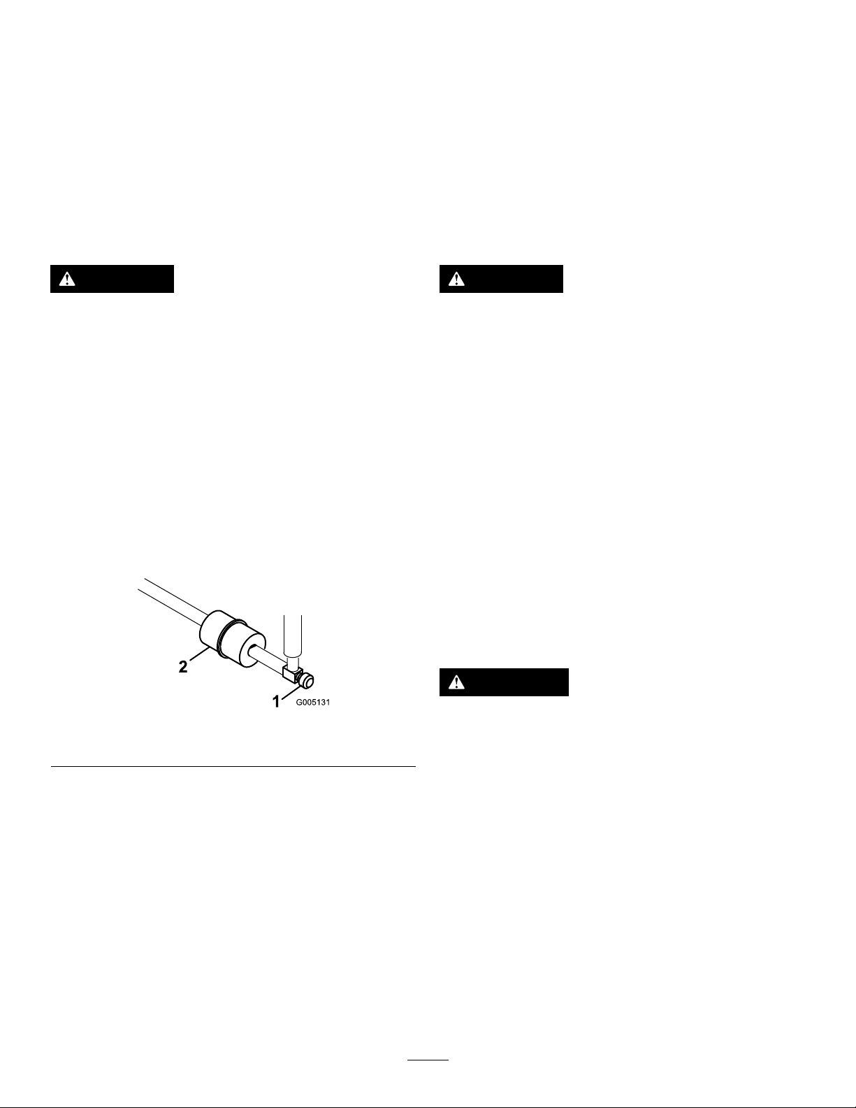
FuelSystem
ElectricalSystem
Maintenance
ReplacingtheFuelFilter
ServiceInterval:Every800hours(Replacesoonerifthefuel
owisrestricted.)
Anin-linelterisincorporatedintothefuellinebetweenthe
fueltankandcarburetor(Figure45).Besurethearrowonthe
lterispointingawayfromthefueltank.
DANGER
Incertainconditions,gasolineisextremely
ammableandhighlyexplosive.Areorexplosion
fromgasolinecanburnyouandothersandcan
damageproperty.
•Draingasolinefromthefueltankwhenthe
engineiscold.Dothisoutdoorsinanopenarea.
Wipeupanygasolinethatspills.
•Neversmokewhendraininggasoline,andstay
awayfromanopenameorwhereasparkmay
ignitethegasolinefumes.
1.Closethefuelshutoffvalve,loosenthehoseclampon
thecarburetorsideoflter,andremovethefuelline
fromthelter(Figure45).
Maintenance
ServicingtheBattery
Properlymaintainthebatteryelectrolyteandkeepthetopof
thebatteryclean.Storethemachineinacoolplacetoprevent
thebatteryfromrunningdown.
Checktheelectrolytelevelevery50operatinghoursor,if
machineisinstorage,every30days.
DANGER
Batteryelectrolytecontainssulfuricacidwhichisa
deadlypoisonandcausessevereburns.
•Donotdrinkelectrolyteandavoidcontactwith
skin,eyesorclothing.Wearsafetyglassesto
shieldyoureyesandrubberglovestoprotect
yourhands.
•Fillthebatterywherecleanwaterisalways
availableforushingtheskin.
Maintainthecelllevelwithdistilledordemineralizedwater.
Donotllthecellsabovethebottomofthesplitringinside
eachcell.
Keepthetopofthebatterycleanbywashingitperiodically
withabrushdippedinammoniaorbicarbonateofsoda
solution.Flushthetopsurfacewithwateraftercleaningit.
Donotremovethellcapswhilecleaningthebattery.
Figure45
1.Fuelshutoffvalve2.Fuellter
2.Placeadrainpanunderthelter,loosentheremaining
hoseclampandremovethelter(Figure45).
3.Installthenewlterwiththearrowonthelterbody
pointingawayfromthefueltank.
InspectingtheFuelLinesand Connections
ServiceInterval:Every2years
Inspectthefuellinesfordeterioration,damage,orloose
connections.
Thebatterycablesmustbetightontheterminalstoprovide
goodelectricalcontact.
WARNING
Incorrectbatterycableroutingcoulddamagethe
tractorandcablescausingsparks.Sparkscancause
thebatterygassestoexplode,resultinginpersonal
injury.
•Alwaysdisconnectthenegative(black)battery
cablebeforedisconnectingthepositive(red)
cable.
•Alwaysconnectthepositive(red)batterycable
beforeconnectingthenegative(black)cable.
Ifcorrosionoccursattheterminals,disconnectthecables,
negative(-)cablerst,andscrapetheclampsandterminals
separately.Reconnectthecables,positive(+)cablerst,and
coattheterminalswithpetroleumjelly.
38
Page 39

WARNING
G017944
2
7.5
7.5
7.5
10
15
C2
1
g014616
1
2
DriveSystem
CALIFORNIA
Proposition65Warning
Batteryposts,terminals,andrelated
accessoriescontainleadandleadcompounds,
chemicalsknowntotheStateofCalifornia
tocausecancerandreproductiveharm.
Washhandsafterhandling.
ServicingtheFuses
Thefusesinthemachine'selectricalsystemarelocatedunder
theseat(Figure46).
Maintenance
AdjustingtheTransmission forNeutral
Ifthemachinecreepswhenthetractioncontrolpedalisin
theneutralposition,theneutralreturnmechanismmustbe
adjusted.
1.Blockupundertheframesothatoneofthefront
wheelsisoffoftheoor.
Note:Note:Ifmachineisequippedwitha3wheel
drivekit,alsoraiseandblockrearwheel.
2.Starttheengine,movethethrottletoSlow,andcheck
thefrontwheelthatisoffoftheoor;itmustnotbe
rotating.
3.Ifthewheelisrotating,stoptheengineandproceed
asfollows:
A.Loosenthenutsecuringtheeccentrictothetop
ofthehydrostat(Figure47).
Figure46
1.Fuses
FuseLayout
LiftReel
HydraulicE-ReelEnable
FanKit
15A7.5A
ReelEngage
Lift/Lower
7.5A
Lights
LeakDetectorLeakDetector
15A7.5A
Run
10A2A
Start/Run
Diag.Lights
Figure47
1.Eccentric2.Locknut
ECMLogic
Power
B.MovethefunctionalcontrollevertoNeutraland
thethrottletoSlow.Starttheengine.
C.Rotatetheeccentricuntilcreepdoesnotoccurin
eitherdirection.Whenthewheelstopsrotating,
tightenthenutlockingtheeccentricandthe
adjustment(Figure47).Verifytheadjustment
withthethrottleintheSlowandFastposition.
Note:Ifthewheelstillturnswhentheeccentric
39
isatthemaximumadjustment,contactyour
AuthorizedServiceDistributororrefertothe
ServiceManualforfurtheradjustment.
Page 40
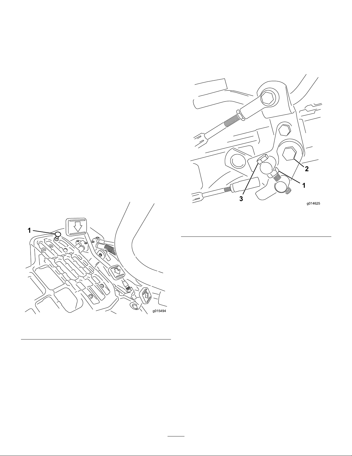
AdjustingtheTransportSpeed
g015494
1
g014625
1
2
3
ObtainingtheMaximumTransport
Speed
Thetractionpedalisadjustedformaximumtransportspeed
atthefactory,butanadjustmentmayberequiredifthepedal
reachesfullstrokebeforeitcontactsthepedalstop,orifa
decreaseintransportspeedisdesired.
Toobtainmaximumtransportspeed,putthefunctional
controlleverinthetransportpositionandpressdownon
thetractionpedal.Ifthepedalcontactsthestop(Figure48)
beforetensionisfeltonthecable,anadjustmentisrequired:
1.Putthefunctionalcontrolleverinthetransport
positionandloosenthelocknutsecuringthepedalstop
totheoorplate(Figure48).
2.Tightenthepedalstopuntilitdoesnotcontactthe
tractionpedal.
3.Continueapplyingalightloadonthetransportpedal
andadjustthepedalstopsoitcontactsthepedalrod
andtightenthenuts.
AdjustingtheMowingSpeed
Themachineisadjustedatthefactory,butspeedmaybe
variedifdesired.
1.Loosenthejamnutonthetrunnionbolt(Figure49).
2.Loosenthenutsecuringthelockandmowbrackets
onthepedalpivot.
Important:Thetensiononthecablemustnotbe
excessiveorcablelifewillbereduced.
Figure48
1.Pedalstop
Figure49
1.Jamnut3.Trunnionbolt
2.Nut
3.Rotatethetrunnionboltclockwisetoreducethe
mowingspeedandcounterclockwisetoincreasethe
mowingspeed.
4.Tightenthejamnutonthetrunnionboltandthenut
onthepedalpivottolocktheadjustment(Figure49).
Checktheadjustmentandadjustasrequired.
ReducingtheTransportSpeed
1.Pressdownonthetractionpedalandloosenthe
locknutsecuringthepedalstoptotheoorplate.
2.Loosenthepedalstopuntilthedesiredtransportspeed
isobtained.
3.Tightenthelocknutsecuringthepedalstop.
40
Page 41

BrakeMaintenance
g014619
1
AdjustingtheBrakes
HydraulicSystem
Maintenance
Ifthebrakefailstoholdthemachinewhileparked,youcan
adjustthebrakesusingthebulkheadttingnearthebrake
drum;contactyourAuthorizedServiceDistributororreferto
theServiceManualformoreinformation.
ChangingtheHydraulicOil andFilter
ServiceInterval:Aftertherst50hours
Every800hours
Iftheoilbecomescontaminated,contactyourlocalToro
distributorbecausethesystemmustbeushed.Contaminated
oillooksmilkyorblackwhencomparedtocleanoil.
1.Cleantheareaaroundtheltermountingarea(Figure
50).Placeadrainpanunderthelterandremovethe
lter.
Note:Iftheoilisnotgoingtobedrained,disconnect
andplugthehydrauliclinegoingtothelter.
Figure50
1.Hydraulicoillter
2.Fillthereplacementlterwiththeappropriatehydraulic
uid,lubricatethesealinggasket,andhandturnituntil
thegasketcontactsthelterhead.Thentighten3/4
turnfurther.Theltershouldnowbesealed.
3.Fillthehydraulicreservoirwithhydraulicoil;referto
ChangingtheHydraulicOilandFilter(page41).
4.Startthemachineandrunitatidlefor3to5minutes
tocirculatetheuidandremoveanyairtrappedin
thesystem.
5.Stopthemachine,rechecktheuidlevelandreplenish
asrequired.
6.Disposeoftheoilandlterproperly.
41
Page 42
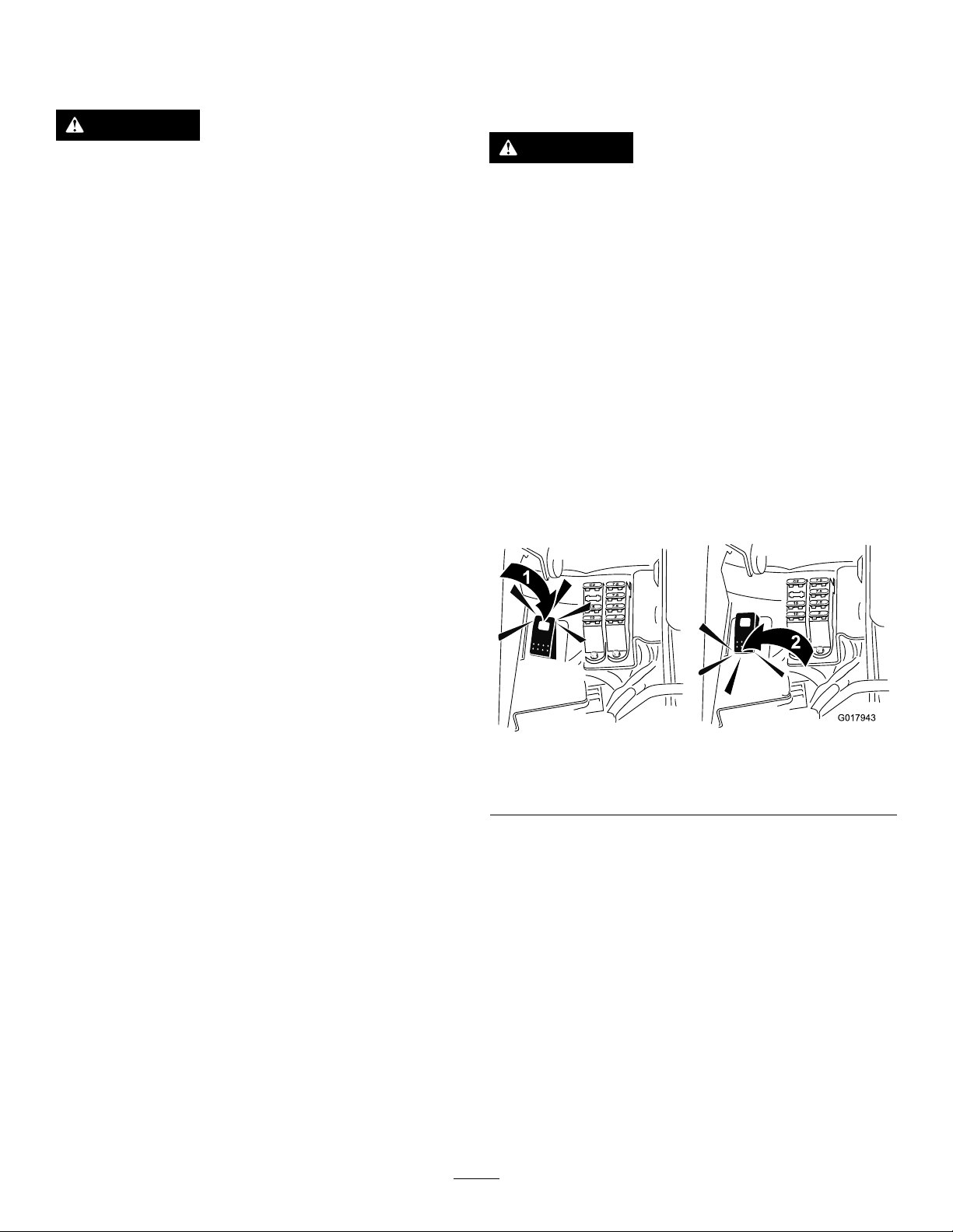
CheckingtheHydraulicLines
G017943
2
2
7.5
7.5
7.5
7.5
7.5
7.5
10
10
15
15
C2
C2
1
2
andHoses
WARNING
Hydraulicuidescapingunderpressurecan
penetrateskinandcauseinjury.
•Makesureallhydraulicuidhosesandlinesare
ingoodconditionandallhydraulicconnections
andttingsaretightbeforeapplyingpressureto
thehydraulicsystem.
•Keepyourbodyandhandsawayfrompin
holeleaksornozzlesthatejecthighpressure
hydraulicuid.
•Usecardboardorpapertondhydraulicleaks.
•Safelyrelieveallpressureinthehydraulicsystem
beforeperforminganyworkonthehydraulic
system.
•Getimmediatemedicalhelpifuidisinjected
intoskin.
Checkthehydrauliclinesandhosesdailyforleaks,kinked
lines,loosemountingsupports,wear,loosettings,weather
deterioration,andchemicaldeterioration.Makeallnecessary
repairsbeforeoperating.
CuttingUnitMaintenance
BacklappingtheReels
WARNING
Contactwiththereelsorothermovingpartscan
resultinpersonalinjury.
•Keepngers,hands,andclothingawayfromthe
reelsorothermovingparts.
•Neverattempttoturnthereelsbyhandorfoot
whiletheengineisrunning.
1.Positionthemachineonalevelsurface,lowerthe
cuttingunits,stoptheengine,engagetheparkingbrake.
2.Removetheplasticcovertotheleftsideoftheseat.
3.Makeinitialreeltobedknifeadjustmentsappropriate
forbacklappingonallcuttingunitswhicharetobe
backlapped;refertotheCuttingUnitOperator’ sManual.
4.Starttheengineandrunatlowidlespeed.Iftheengine
stalls,increasetheenginespeed.
5.SwitchtheBacklapSwitchtotheReverse(R)position
(Figure51).
Figure51
1.Backlapswitch—backlap
position
2.Backlapswitch—mow
position
6.OntheInfoCenterpulluptheMainMenuandscroll
downtoSettings.
7.IntheSettingsmenuscrolldowntoBacklaprpmand
usethe±buttontoselectthedesiredbacklapspeed.
8.Withthefunctionalcontrolleverintheneutralposition,
movetheRaise/LowerMowcontrolforwardtostart
thebacklappingoperationonthedesignatedreels.
9.Applylappingcompoundwithalonghandlebrush.
Neveruseashorthandledbrush.
10.Ifthereelsstallorbecomeerraticwhilebacklapping,
selectahigherreelspeedsettinguntilthespeed
42
stabilizes.
11.Tomakeanadjustmenttothecuttingunitswhile
backlapping,turnthereelsoffbymovingthe
Raise/LowerMowcontrolrearwardandstopthe
Page 43

engine.Aftercompletingadjustments,repeatsteps4
through9.
Storage
12.Repeattheprocedureforallcuttingunitsyouwantto
backlap.
13.Whennished,returntheBacklapSwitchtothe
Forward(F)position,replacethecover,andwashall
thelappingcompoundoffofthecuttingunits.Adjust
thecuttingunitreeltobedknifeasneeded.Movethe
cuttingunitreelspeedcontroltothedesiredmowing
position.
Important:Ifthebacklapswitchisnotreturned
totheForward(F)positionafterbacklapping,the
cuttingunitswillnotraiseorfunctionproperly.
Ifyouwishtostorethemachineforalongperiodoftime,the
followingstepsshouldbeperformedpriortostorage:
1.Removeaccumulationsofdirtandoldgrassclippings.
Sharpenthereelsandbedknives,ifnecessary;refer
totheCuttingUnitOperator'sManual.Usearust
preventiveonbedknivesandreelblades.Greaseand
oilalllubricationpoints;refertoLubrication(page36).
2.Blockupthewheelstoremoveanyweightonthetires.
3.Drainandreplacethehydraulicuidandlterand
inspectthehydrauliclinesandttings.Replace,if
necessary;refertoChangingtheHydraulicOiland
Filter(page41)andCheckingtheHydraulicLinesand
Hoses(page42).
4.Allfuelshouldberemovedfromthefueltank.Runthe
engineuntilitstopsfromlackoffuel.Replacethefuel
lter;refertoReplacingtheFuelFilter(page38).
5.Whiletheengineisstillwarm,draintheoilfromthe
crankcase.Rellitwithfreshoil;refertoChangingthe
EngineOilandFilter(page37).
6.Removethesparkplugs,pouroneounceofSAE30oil
intothecylinders,andcrankslowlytodistributetheoil.
Replacethesparkplugs;refertoReplacingtheSpark
Plugs(page37).
7.Cleandirtandchafffromthecylinder,cylinderhead
ns,andblowerhousing.
8.Removethebatteryandchargeitfully.Eitherstore
itontheshelforonthemachine.Leavethecables
disconnectedifitisstoredonthemachine.Store
thebatteryinacoolatmospheretoavoidquick
deteriorationofthechargeinthebattery.
9.Ifpossible,storethemachineinawarm,drylocation.
43
Page 44

TheToroTotalCoverageGuarantee
ALimitedWarranty
ConditionsandProductsCovered
TheToroCompanyanditsafliate,T oroWarrantyCompany,pursuant
toanagreementbetweenthem,jointlywarrantyourT oroCommercial
product(“Product”)tobefreefromdefectsinmaterialsorworkmanship
fortwoyearsor1500operationalhours*,whicheveroccursrst.This
warrantyisapplicabletoallproductswiththeexceptionofAerators
(refertoseparatewarrantystatementsfortheseproducts).Wherea
warrantableconditionexists,wewillrepairtheProductatnocosttoyou
includingdiagnostics,labor,parts,andtransportation.Thiswarranty
beginsonthedatetheProductisdeliveredtotheoriginalretailpurchaser.
*Productequippedwithanhourmeter.
InstructionsforObtainingWarrantyService
YouareresponsiblefornotifyingtheCommercialProductsDistributoror
AuthorizedCommercialProductsDealerfromwhomyoupurchasedthe
Productassoonasyoubelieveawarrantableconditionexists.Ifyouneed
helplocatingaCommercialProductsDistributororAuthorizedDealer,or
ifyouhavequestionsregardingyourwarrantyrightsorresponsibilities,
youmaycontactusat:
ToroCommercialProductsServiceDepartment
ToroWarrantyCompany
811 1LyndaleAvenueSouth
Bloomington,MN55420-1196
952–888–8801or800–952–2740
E-mail:commercial.warranty@toro.com
OwnerResponsibilities
AstheProductowner,youareresponsibleforrequiredmaintenanceand
adjustmentsstatedinyourOperator'sManual.Failuretoperformrequired
maintenanceandadjustmentscanbegroundsfordisallowingawarranty
claim.
ItemsandConditionsNotCovered
Notallproductfailuresormalfunctionsthatoccurduringthewarranty
periodaredefectsinmaterialsorworkmanship.Thiswarrantydoesnot
coverthefollowing:
•Productfailureswhichresultfromtheuseofnon-T ororeplacement
parts,orfrominstallationanduseofadd-on,ormodiednon-Toro
brandedaccessoriesandproducts.Aseparatewarrantymaybe
providedbythemanufactureroftheseitems.
•Productfailureswhichresultfromfailuretoperformrecommended
maintenanceand/oradjustments.Failuretoproperlymaintainyour
ToroproductpertheRecommendedMaintenancelistedinthe
Operator’sManualcanresultinclaimsforwarrantybeingdenied.
•ProductfailureswhichresultfromoperatingtheProductinanabusive,
negligent,orrecklessmanner.
•Partssubjecttoconsumptionthroughuseunlessfoundtobedefective.
Examplesofpartswhichareconsumed,orusedup,duringnormal
Productoperationinclude,butarenotlimitedto,brakepadsand
linings,clutchlinings,blades,reels,rollersandbearings(sealedor
greasable),bedknives,sparkplugs,castorwheelsandbearings,tires,
lters,belts,andcertainsprayercomponentssuchasdiaphragms,
nozzles,andcheckvalves,etc.
•Failurescausedbyoutsideinuence.Conditionsconsideredtobe
outsideinuenceinclude,butarenotlimitedto,weather,storage
practices,contamination,useofunapprovedfuels,coolants,lubricants,
additives,fertilizers,water,orchemicals,etc.
•Failureorperformanceissuesduetotheuseoffuels(e.g.gasoline,
diesel,orbiodiesel)thatdonotconformtotheirrespectiveindustry
standards.
•Normalnoise,vibration,wearandtear ,anddeterioration.
•Normal“wearandtear”includes,butisnotlimitedto,damagetoseats
duetowearorabrasion,wornpaintedsurfaces,scratcheddecalsor
windows,etc.
Parts
Partsscheduledforreplacementasrequiredmaintenancearewarranted
fortheperiodoftimeuptothescheduledreplacementtimeforthatpart.
Partsreplacedunderthiswarrantyarecoveredforthedurationofthe
originalproductwarrantyandbecomethepropertyofT oro.T orowillmake
thenaldecisionwhethertorepairanyexistingpartorassemblyorreplace
it.T oromayuseremanufacturedpartsforwarrantyrepairs.
DeepCycleandLithium-IonBatteryWarranty:
DeepcycleandLithium-Ionbatterieshaveaspeciedtotalnumberof
kilowatt-hourstheycandeliverduringtheirlifetime.Operating,recharging,
andmaintenancetechniquescanextendorreducetotalbatterylife.Asthe
batteriesinthisproductareconsumed,theamountofusefulworkbetween
chargingintervalswillslowlydecreaseuntilthebatteryiscompletelyworn
out.Replacementofwornoutbatteries,duetonormalconsumption,
istheresponsibilityoftheproductowner.Batteryreplacementmaybe
requiredduringthenormalproductwarrantyperiodatowner’sexpense.
Note:(Lithium-Ionbatteryonly):ALithium-Ionbatteryhasapartonly
proratedwarrantybeginningyear3throughyear5basedonthetime
inserviceandkilowatthoursused.RefertotheOperator'sManualfor
additionalinformation.
MaintenanceisatOwner’sExpense
Enginetune-up,lubrication,cleaningandpolishing,replacementoflters,
coolant,andcompletingrecommendedmaintenancearesomeofthe
normalservicesT oroproductsrequirethatareattheowner’sexpense.
GeneralConditions
RepairbyanAuthorizedToroDistributororDealerisyoursoleremedy
underthiswarranty.
NeitherTheToroCompanynorToroWarrantyCompanyisliablefor
indirect,incidentalorconsequentialdamagesinconnectionwiththe
useoftheToroProductscoveredbythiswarranty,includingany
costorexpenseofprovidingsubstituteequipmentorserviceduring
reasonableperiodsofmalfunctionornon-usependingcompletion
ofrepairsunderthiswarranty.ExceptfortheEmissionswarranty
referencedbelow,ifapplicable,thereisnootherexpresswarranty.All
impliedwarrantiesofmerchantabilityandtnessforusearelimitedto
thedurationofthisexpresswarranty.
Somestatesdonotallowexclusionsofincidentalorconsequential
damages,orlimitationsonhowlonganimpliedwarrantylasts,sotheabove
exclusionsandlimitationsmaynotapplytoyou.Thiswarrantygivesyou
speciclegalrights,andyoumayalsohaveotherrightswhichvaryfrom
statetostate.
Noteregardingenginewarranty:
TheEmissionsControlSystemonyourProductmaybecoveredby
aseparatewarrantymeetingrequirementsestablishedbytheU.S.
EnvironmentalProtectionAgency(EP A)and/ortheCaliforniaAirResources
Board(CARB).Thehourlimitationssetforthabovedonotapplytothe
EmissionsControlSystemWarranty.RefertotheEngineEmissionControl
WarrantyStatementsuppliedwithyourproductorcontainedintheengine
manufacturer’sdocumentationfordetails
CountriesOtherthantheUnitedStatesorCanada
CustomerswhohavepurchasedT oroproductsexportedfromtheUnitedStatesorCanadashouldcontacttheirT oroDistributor(Dealer)toobtain
guaranteepoliciesforyourcountry ,province,orstate.IfforanyreasonyouaredissatisedwithyourDistributor'sserviceorhavedifcultyobtaining
guaranteeinformation,contacttheT oroimporter.
374-0253RevB
 Loading...