

Page 1
FormNo.3398-694RevA
g014597
Greensmaster
®
3400TriFlex
TractionUnit
ModelNo.04520—SerialNo.316000001andUp
®
Registeratwww.T oro.com.
OriginalInstructions(EN)
*3398-694*A
Page 2
ThisproductcomplieswithallrelevantEuropeandirectives;
g014685
1
fordetails,pleaseseetheseparateproductspecicDeclaration
ofConformity(DOC)sheet.
WARNING
CALIFORNIA
Proposition65Warning
Thisproductcontainsachemicalorchemicals
knowntotheStateofCaliforniatocausecancer,
birthdefects,orreproductiveharm.
Theengineexhaustfromthisproduct
containschemicalsknowntotheStateof
Californiatocausecancer,birthdefects,
orotherreproductiveharm.
Figure1
ThissparkignitionsystemcomplieswithCanadianICES-002.
ItisaviolationofCaliforniaPublicResourceCode
Section4442or4443touseoroperatetheengineonany
forest-covered,brush-covered,orgrass-coveredlandunless
theengineisequippedwithasparkarrester,asdenedin
Section4442,maintainedineffectiveworkingorderorthe
engineisconstructed,equipped,andmaintainedforthe
preventionofre.
Introduction
Thismachineisaride-on,reel-bladelawnmowerintended
tobeusedbyprofessional,hiredoperatorsincommercial
applications.Itisprimarilydesignedforcuttinggrasson
well-maintainedlawnsinparks,golfcourses,sportselds,
andoncommercialgrounds.Itisnotdesignedforcutting
brush,mowinggrassandothergrowthalongsidehighways,
orforagriculturaluses.
Readthisinformationcarefullytolearnhowtooperateand
maintainyourproductproperlyandtoavoidinjuryand
productdamage.Youareresponsibleforoperatingthe
productproperlyandsafely.
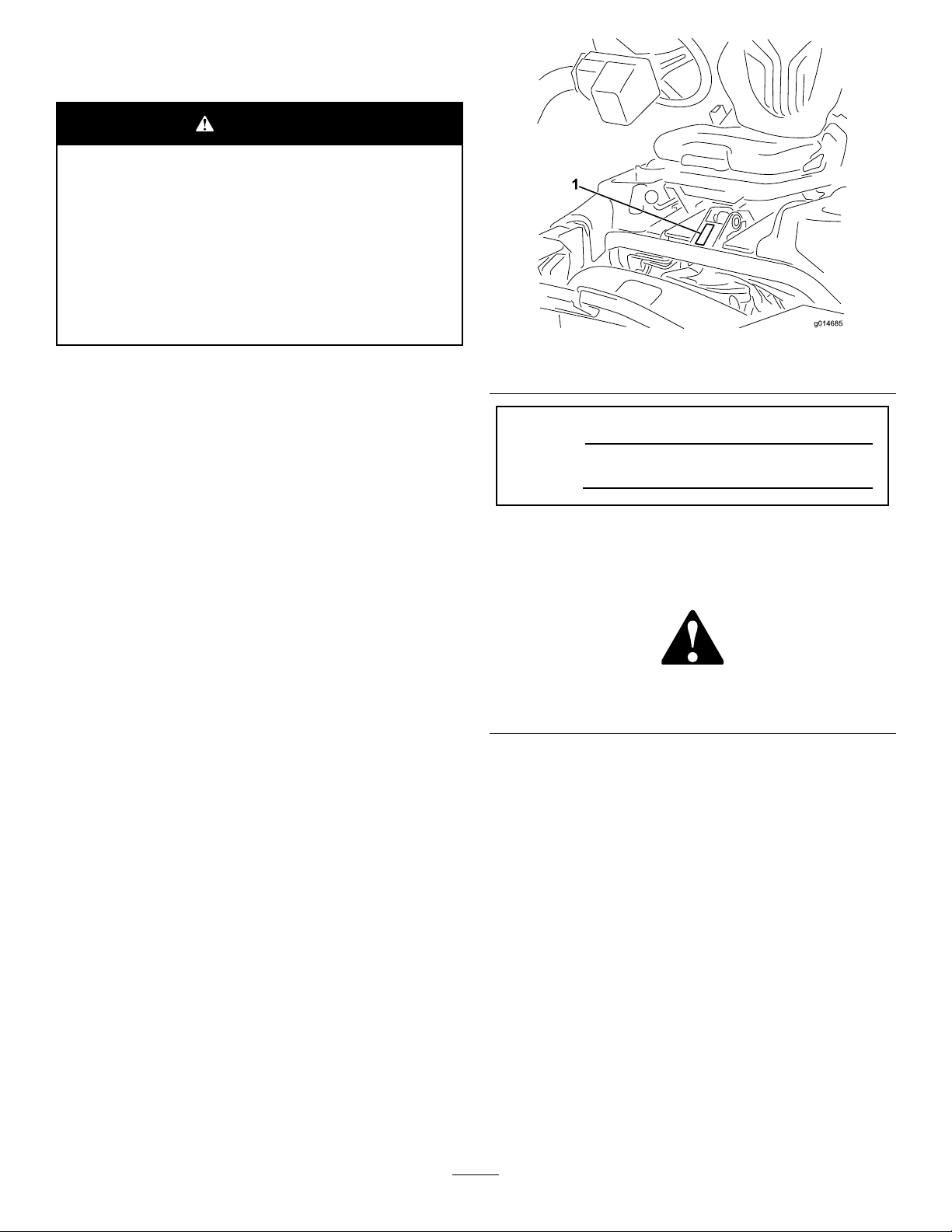
1.Modelandserialnumberlocation
ModelNo.
SerialNo.
Thismanualidentiespotentialhazardsandhassafety
messagesidentiedbythesafety-alertsymbol(Figure2),
whichsignalsahazardthatmaycauseseriousinjuryordeath
ifyoudonotfollowtherecommendedprecautions.
Figure2
1.Safety-alertsymbol
Thismanualuses2wordstohighlightinformation.
Importantcallsattentiontospecialmechanicalinformation
andNoteemphasizesgeneralinformationworthyofspecial
attention.
YoumaycontactTorodirectlyatwww .Toro.comforproduct
andaccessoryinformation,helpndingadealer,ortoregister
yourproduct.
Wheneveryouneedservice,genuineT oroparts,oradditional
information,contactanAuthorizedServiceDealerorToro
CustomerServiceandhavethemodelandserialnumbersof
yourproductready.Figure1identiesthelocationofthe
modelandserialnumbersontheproduct.Writethenumbers
inthespaceprovided.
©2015—TheToro®Company
8111LyndaleAvenueSouth
Bloomington,MN55420
Contactusatwww.Toro.com.
2
PrintedintheUSA
AllRightsReserved
Page 3

Contents
Safety...........................................................................4
SafeOperatingPractices...........................................4
ToroMowerSafety..................................................5
SoundPowerLevel..................................................6
SoundPressureLevel...............................................6
Hand-ArmVibrationLevel......................................6
WholeBodyVibrationLevel....................................6
SafetyandInstructionalDecals.................................7
Setup...........................................................................11
1InstallingtheRollBar...........................................12
2InstallingtheSeat.................................................12
3InstallingtheSteeringWheel..................................12
4ActivatingandChargingtheBattery........................12
5InstallingtheOilCooler(optional).........................14
6InstallingtheGrass-BasketHooks..........................14
7InstallingtheCuttingUnits...................................15
8AddingRearWeight.............................................15
9InstallingEUDecals.............................................15
10ReducingtheTirePressure..................................15
11BurnishingtheBrakes.........................................15
ProductOverview.........................................................16
Controls...............................................................16
Specications........................................................19
Attachments/Accessories........................................19
Operation....................................................................20
ThinkSafetyFirst...................................................20
CheckingtheEngineOil..........................................20
FillingtheFuelTank...............................................21
UsingBiodieselFuel...............................................22
CheckingtheCoolingSystem...................................23
CheckingtheHydraulic-FluidLevel..........................23
DrainingWaterfromtheFuelFilter...........................24
CheckingtheReel-to-BedknifeContact.....................25
CheckingtheTirePressure......................................25
CheckingtheTorqueoftheWheelNuts.....................25
BreakingintheMachine..........................................25
StartingandStoppingtheEngine..............................25
CheckingtheSafetyInterlockSystem........................26
InstallingandRemovingtheCuttingUnits.................26
SettingtheReelSpeed.............................................29
Mowing................................................................29
InspectingandCleaningafterMowing.......................30
DrivingtheMachinewithoutMowing.......................30
TransportingtheMachine........................................30
TowingtheMachine...............................................31
Maintenance.................................................................33
RecommendedMaintenanceSchedule(s)......................33
DailyMaintenanceChecklist....................................34
EngineMaintenance..................................................35
ServicingtheAirCleaner.........................................35
ChangingtheEngineOilandFilter...........................35
FuelSystemMaintenance...........................................36
ReplacingtheFuelFilter/WaterSeparator..................36
InspectingtheFuelLinesandConnections.................37
ElectricalSystemMaintenance....................................37
ServicingtheBattery...............................................37
StoringtheBattery..................................................38
LocatingtheFuses..................................................38
Jump-StartingtheMachine......................................39
DriveSystemMaintenance.........................................39
AdjustingtheTransmissionforNeutral.....................39
AdjustingtheTransportSpeed.................................40
AdjustingtheMowingSpeed....................................41
CoolingSystemMaintenance......................................41
CleaningtheRadiatorScreen....................................41
BrakeMaintenance....................................................42
AdjustingtheBrakes...............................................42
BeltMaintenance......................................................42
AdjustingtheAlternatorBelt...................................42
HydraulicSystemMaintenance....................................43
ChangingtheHydraulicFluidandFilter.....................43
CheckingtheHydraulicLinesandHoses....................43
CuttingUnitMaintenance...........................................44
BacklappingtheReels.............................................44
DiagnosticsSystem....................................................45
DiagnosingtheServiceIndicatorLight......................45
Storage........................................................................45
3
Page 4

Safety
Thismachinehasbeendesignedinaccordancewith
ENISO5395:2013andANSIB71.4-2012andmeetsthese
standardswhentheappropriateweightkitisadded.
Improperuseormaintenancebytheoperatororowner
canresultininjury.Toreducethepotentialforinjury,
complywiththesesafetyinstructionsandalwayspay
attentiontothesafetyalertsymbol(Figure2),which
meansCaution,Warning,orDanger—personalsafety
instruction.Failuretocomplywiththeinstructionmay
resultinpersonalinjuryordeath.
SafeOperatingPractices
Training
•ReadtheOperator'sManualandothertrainingmaterial.If
theoperator(s)ormechanic(s)cannotreadthemanualitis
theowner'sresponsibilitytoexplainthismaterialtothem.
•Becomefamiliarwiththesafeoperationoftheequipment,
operatorcontrols,andsafetysigns.
•Alloperatorsandmechanicsshouldbetrained.The
ownerisresponsiblefortrainingtheusers.
•Neverletchildrenoruntrainedpeopleoperateorservice
theequipment.Localregulationsmayrestricttheageof
theoperator.
•Theowner/usercanpreventandisresponsiblefor
accidentsorinjuriesoccurringtopeopleorproperty.
Preparation
•Evaluatetheterraintodeterminewhataccessoriesand
attachmentsareneededtoproperlyandsafelyperform
thejob.Useonlyaccessoriesandattachmentsapproved
bythemanufacturer.
•Wearappropriateclothingincludingsubstantial,
slip-resistantfootwear,safetyglasses,andhearing
protection.Tiebacklonghair.Donotwearjewelry.
•Inspecttheareawhereyouwillusetheequipmentand
removeallobjectsthatcouldbethrownbythemachine,
suchasrocks,toys,andwire.
•Checkthatoperatorpresencecontrols,safetyswitches,
andguardsareattachedandfunctioningproperly .Donot
operatethemachineunlesstheyarefunctioningproperly.
Operation
•Donotoperatetheengineinaconnedspacewhere
dangerouscarbonmonoxideandotherexhaustgasses
cancollect.
•Operatethemachineonlyingoodlight,keepingaway
fromholesandhiddenhazards.
•Besurealldrivesareinneutralandparkingbrakeis
engagedbeforestartingengine.Startengineonlyfrom
theoperator'sposition.
•Slowdownanduseextracareonhillsides.Turfconditions
canaffectthemachine'sstability.Usecautionwhile
operatingneardrop-offs.
•Slowdownandusecautionwhenmakingturnsandwhen
changingdirectionsonslopes.
•Neveroperatewithoutguardssecurelyinplace.Besure
allinterlocksareattached,adjusted,andfunctioning
properly.
•Donotchangetheenginegovernorsettingoroverspeed
theengine.
•Stopthemachineonlevelground,lowerthecuttingunits,
disengagethedrives,engagetheparkingbrake,andshut
offtheenginebeforeleavingtheoperator'spositionfor
anyreason,includingemptyingthegrassbaskets.
•Stopandinspectthemachineafterstrikingobjectsorif
anabnormalvibrationoccurs.Makenecessaryrepairs
beforeresumingoperations.
•Keephandsandfeetawayfromthecuttingunits.
•Lookbehindanddownbeforebackinguptobesureof
aclearpath.
•Nevercarrypassengersandkeeppetsandbystanders
away.
•Slowdownandusecautionwhenmakingturnsand
crossingroadsandsidewalks.Stopthereelsifnot
mowing.
•Donotoperatethemachinewhentired,ill,orunderthe
inuenceofalcoholordrugs.
•Lightningcancausesevereinjuryordeath.Iflightning
isseenorthunderisheardinthearea,donotoperate
themachine;seekshelter.
•Usecarewhenloadingorunloadingthemachineintoa
trailerortruck.
•Usecarewhenapproachingblindcorners,shrubs,trees,
orotherobjectsthatmayobscurevision.
RolloverProtectionSystem
(ROPS)—UseandMaintenance
•TheROPSisanintegralandeffectivesafetydevice.Use
theseatbeltwhenoperatingthemachine.
•Ensurethatyoucanreleasetheseatbeltquicklyinthe
eventofanemergency.
•Checkcarefullyforoverheadclearances(i.e.branches,
doorways,electricalwires)beforedrivingunderany
objectsanddonotcontactthem.
•KeeptheROPSinsafeoperatingconditionby
periodicallythoroughlyinspectingfordamageand
keepingallmountingfastenerstight.
•ReplaceadamagedROPS.Donotrepairorrevise.
•DonotremovetheROPS.
•AnyalterationstoaROPSmustbeapprovedbythe
manufacturer.
4
Page 5

MaintenanceandStorage
•Parkthemachineonlevelground,disengagethedrives,
lowerthecuttingunits,settheparkingbrake,stopthe
engine,removethekey,anddisconnectsparkplugwire(s).
Waitforallmovementtostopbeforeadjusting,cleaning,
orrepairingthemachine.
•Cleangrassanddebrisfromcuttingunits,drives,mufers,
andtheenginetohelppreventres.Cleanupoilorfuel
spills.
•Lettheenginecoolbeforestoringanddonotstorethe
machinenearames.
•Shutoffthefuelwhilestoringortransportingthe
machine.Donotstorefuelnearamesordrainthefuel
tankindoors.
•Neverallowuntrainedpersonneltoservicethemachine.
•Usejackstandstosupportcomponentswhenrequired.
•Carefullyreleasepressurefromcomponentswithstored
energy.
•Disconnectthebatteryandremovethesparkplugwire(s)
beforemakinganyrepairs.Disconnectthenegative
terminalrstandthepositivelast.Connectthepositive
terminalrstandthenegativeterminallast.
•Usecareandweargloveswhencheckingthereels.
•Keephandsandfeetawayfrommovingparts.Ifpossible,
donotmakeadjustmentswiththeenginerunning.
•Chargebatteriesinanopen,well-ventilatedarea,away
fromsparkandames.Unplugthechargerbefore
connectingordisconnectingitfromthebattery.Wear
protectiveclothinganduseinsulatedtools.
•Keepallpartsingoodworkingconditionandallhardware
andhydraulicttingstightened.Replaceallwornor
damageddecals.
ToroMowerSafety
ThefollowinglistcontainssafetyinformationspecictoToro
productsorothersafetyinformationthatyoumustknowthat
isnotincludedintheANSIstandards.
Thisproductiscapableofamputatinghandsandfeetand
ofthrowingobjects.Alwaysfollowallsafetyinstructionsto
avoidseriousinjuryordeath.
Useofthisproductforpurposesotherthanitsintendeduse
couldprovedangeroustouserandbystanders.
Operation
•Knowhowtostoptheenginequickly.
•Checkthesafetyinterlockswitchesdailyforproper
operation.
•Beforeattemptingtostarttheengine,disengageallblade
attachmentclutches,shiftintoneutral,andengagethe
parkingbrake.
•Usingthemachinedemandsattention.Topreventloss
ofcontrol:
–Donotdriveclosetosandtraps,ditches,creeks,or
otherhazards.
–Reducespeedwhenmakingsharpturns.Avoid
suddenstopsandstarts.
–Thismachineisnotdesignedorequippedforon-road
useandisa“slow-movingvehicle.”Ifyoumustcross
ortravelonapublicroad,youshouldbeawareofand
complywithlocalregulations,suchasrequiredlights,
slow-movingvehiclesigns,andreectors.
–Watchoutfortrafcwhennearorcrossingroads.
Alwaysyieldtheright-of-way.
–Applytheservicebrakeswhengoingdownhillto
keepforwardspeedslowandtomaintaincontrolof
themachine.
•Thegrassbasketsmustbeinplaceduringoperation
ofthereelsorthatchersformaximumsafety.Shutthe
engineoffbeforeemptyingthebaskets.
•Raisethecuttingunitswhendrivingfromoneworkarea
toanother.
•Donottouchtheengine,mufer,orexhaustpipewhile
theengineisrunningorsoonafterithasstoppedbecause
theseareascouldbehotenoughtocauseburns.
•Stayclearoftherotatingscreenatthesideoftheengine
topreventdirectcontactwithyourbodyorclothing.
•Ifacuttingunitstrikesasolidobjectorvibrates
abnormally,stopimmediately,turntheengineoff,waitfor
allmotiontostop,andinspectthemachinefordamage.
Repairorreplaceadamagedreelorbedknifebefore
continuingoperation.
•Beforegettingofftheseat,movethefunctionalcontrol
levertoNEUTRAL,raisethecuttingunits,andwaitforthe
reelstostopspinning.Settheparkingbrake.Stopthe
engineandremovethekeyfromtheignitionswitch.
•Traverseslopescarefully.Donotstartorstopsuddenly
whentravelinguphillordownhill.
•Theoperatormustbeskilledandtrainedinhowtodrive
onhillsides.Failuretousecautiononslopesorhillsmay
causelossofcontrolandcausethemachinetotiporroll,
possiblyresultinginpersonalinjuryordeath.
•Iftheenginestallsorlosesheadwayandcannotmakeit
tothetopofaslope,donotturnthemachinearound.
Alwaysbackslowly,straightdowntheslope.
•Whenapersonoranimalappearsunexpectedlyinor
nearthemowingarea,stopmowing.Carelessoperation,
combinedwithterrainangles,ricochets,orimproperly
positionedguardscanleadtothrown-objectinjuries.Do
notresumemowinguntiltheareaiscleared.
MaintenanceandStorage
•Ensurethatallhydrauliclineconnectorsaretightandthat
allhydraulichosesandlinesareingoodconditionbefore
applyingpressuretothesystem.
•Keepyourbodyandhandsawayfrompin-holeleaksor
nozzlesthatejecthydraulicuidunderhighpressure.
5
Page 6

Usepaperorcardboard,notyourhands,tosearchfor
leaks.Hydraulicuidescapingunderpressurecanhave
sufcientforcetopenetratetheskinandcauseserious
injury.
SoundPowerLevel
Thisunithasaguaranteedsoundpowerlevelof98dBA,
whichincludesanUncertaintyValue(K)of1dBA.
•Beforedisconnectingorperforminganyworkonthe
hydraulicsystem,allpressureinthesystemmustbe
relievedbystoppingtheengineandloweringthecutting
unitsandattachmentstotheground.
•Checkallfuellinesfortightnessandwearonaregular
basis.Tightenorrepairthemasneeded.
•Iftheenginemustberunningtoperformamaintenance
adjustment,keephands,feet,clothing,andanypartsof
thebodyawayfromthecuttingunits,attachments,and
anymovingparts,especiallythescreenatthesideofthe
engine.Keepeveryoneaway.
•Donotoverspeedtheenginebychanginggovernor
settings.Toensuresafetyandaccuracy,havean
AuthorizedToroDistributorcheckthemaximumengine
speedwithatachometer..
•Theenginemustbeshutoffbeforecheckingtheoilor
addingoiltothecrankcase.
•Ifmajorrepairsareeverneededorifassistanceisdesired,
contactanAuthorizedToroDistributor.
•Toensureoptimumperformanceandcontinuedsafety
certicationofthemachine,useonlygenuineToro
replacementpartsandaccessories.Replacementparts
andaccessoriesmadebyothermanufacturerscouldbe
dangerous,andsuchusecouldvoidtheproductwarranty.
Soundpowerlevelwasdeterminedaccordingtothe
proceduresoutlinedinISO11094.
SoundPressureLevel
Thisunithasasoundpressurelevelattheoperator’searof84
dBA,whichincludesanUncertaintyValue(K)of1dBA.
Soundpressurelevelwasdeterminedaccordingtothe
proceduresoutlinedinENISO5395:2013.
Hand-ArmVibrationLevel
Measuredvibrationlevelforrighthand=0.22m/s
Measuredvibrationlevelforlefthand=0.24m/s
UncertaintyValue(K)=0.24m/s
Measuredvaluesweredeterminedaccordingtotheprocedures
outlinedinENISO5395:2013.
2
2
2
WholeBodyVibrationLevel
Measuredvibrationlevel=0.41m/s
UncertaintyValue(K)=0.21m/s
2
2
Measuredvaluesweredeterminedaccordingtotheprocedures
outlinedinENISO5395:2013.
6
Page 7

SafetyandInstructionalDecals
Safetydecalsandinstructionsareeasilyvisibletotheoperatorandarelocatednearanyareaofpotential
danger.Replaceanydecalthatisdamagedorlost.
119-9343
115-8156
1.Reelheight3.8Bladecuttingunit5.14Bladecuttingunit7.Fast
2.5Bladecuttingunit4.11Bladecuttingunit6.Reelspeed
8.Slow
7
Page 8
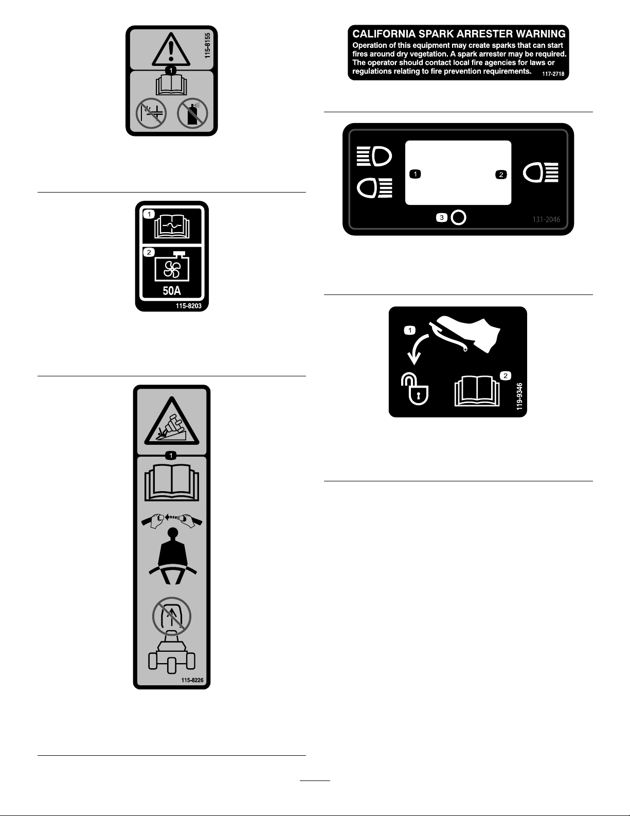
115-8155
1.Warning—readtheOperator'sManual,donotprimeoruse
startinguid.
117–2718
131-2046
1.ReadtheOperator's
manualforfuse
information.
115-8203
2.Radiatorfan—50Amp
1.Doublelights
2.Singlelight
1.Presspedaltounlock
3.Off
119-9346
2.ReadtheOperator's
Manualformore
information.
115-8226
1.Tippinghazard—readtheOperator'smanual;alwayswear
aseatbeltwhenoperating;donotremovetherollover
protectionsystem(ROPS).
8
Page 9

BatterySymbols
Someorallofthesesymbolsareonyourbattery .
1.Explosionhazard
2.Nore,openames,or
smoking.
3.Causticliquid/chemical
burnhazard
4.Weareyeprotection.9.Flusheyesimmediately
5.ReadtheOperator’s
Manual.
6.Keepbystandersasafe
7.Weareyeprotection;
8.Batteryacidcancause
10.Containslead;donot
distancefromthebattery.
explosivegasescan
causeblindnessandother
injuries.
blindnessorsevereburns.
withwaterandgetmedical
helpfast.
discard.
132-9548
1.Enginespeed—fast
2.Enginespeed—slow8.Reel—transport
3.Lowerandengagethereels9.Reel—mow
4.Raiseanddisengagethereels10.Reel—backlaping
5.Reelspeed—fast11.Moveforward
6.Reelspeed—slow
7.Reelspeed—neutral
9
Page 10
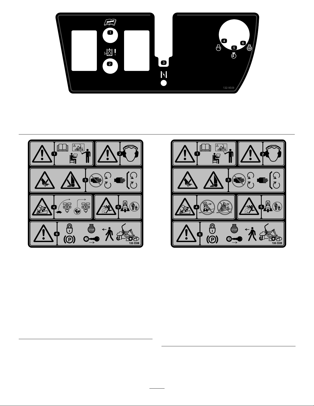
132-9549
1.ReadtheOperator'sManualbeforeservicingorperforming
maintenance.
2.Hydraulicuidlevel
3.Choke
133-2338
1.Warning—readthe
Operator’sManual,do
notoperatethismachine
unlessyouaretrained.
2.Warning—wearhearing
protection.
3.Cutting/dismemberment
hazardofhandorfoot,
mowerblade—stayaway
frommovingparts;keep
allguardsandshieldsin
place.
4.Tippinghazard—slow
machinebeforeturning,
donotturnathighspeeds.
5.Thrownobject
hazard—keepbystanders
asafedistancefromthe
machine.
6.Warning—locktheparking
brake,stoptheengine
andremovetheignition
keybeforeleavingthe
machine.
4.Engine—start
5.Engine—run
6.Engine—stop
ReplacesDecal133-2338forCEMachines
1.Warning—readthe
Operator’sManual,do
notoperatethismachine
unlessyouaretrained.
2.Warning—wearhearing
protection.
3.Cutting/dismemberment
hazardofhandorfoot,
mowerblade—stayaway
frommovingparts;keep
allguardsandshieldsin
place.
133-2339
4.Tippinghazard—donot
driveacrossordown
slopesgreaterthan15
degrees.
5.Thrownobject
hazard—keepbystanders
asafedistancefromthe
machine.
6.Warning—locktheparking
brake,stoptheengine
andremovetheignition
keybeforeleavingthe
machine.
10
Page 11

Setup
LooseParts
Usethechartbelowtoverifythatallpartshavebeenshipped.
ProcedureDescription
1
2
3
4
5
6
7
8
Rollbar1
Bolt(1/2x3-3/4inches)
Flange-nut(1/2inch)
Seat-completionkit
Steeringwheel
Locknut(1-1/2inches)
Washer1
Steering-wheelcap
Nopartsrequired
Nopartsrequired
Grass-baskethook
Flangebolts12
Gaugebar
Cuttingunit(obtainfromyourT oro
Distributor)
Grassbasket
WeightKit,121-6665(purchase
separately)Note:Thiskitisnotrequired
forunitswiththe3wheeldrivekit
installed.
Qty.
4
4
1Installtheseattothebase.
1
1
1
–
–
6
1
3
3
1Addrearweight.
Installtherollbar.
Installthesteeringwheel.
Activateandchargethebattery.
Installtheoptionaloilcooler.
Installthegrass-baskethooks.
Installthecuttingunits.
Use
9
10
11
Warningdecal,133-23381
Nopartsrequired
Nopartsrequired
MediaandAdditionalParts
Description
Operator'sManual(machine)
Engineoperator'smanual(engine)
PartsCatalog
Operatortrainingmaterials
Pre-deliveryInspectionSheet
Noiseratingcerticate
Certicateofcompliance
Ignitionkeys2
Qty.
InstallEUdecals,ifrequired.
–
–
1
1
1
1
1
1
1
Readbeforeoperatingthemachine
Saveforfuturepartsordering
Viewbeforeoperatingthemachine
Saveforfuturereference
Starttheengine
Reducethetirepressure.
Burnishthebrakes.
Use
11
Page 12
1
g014601
1
2
3
2
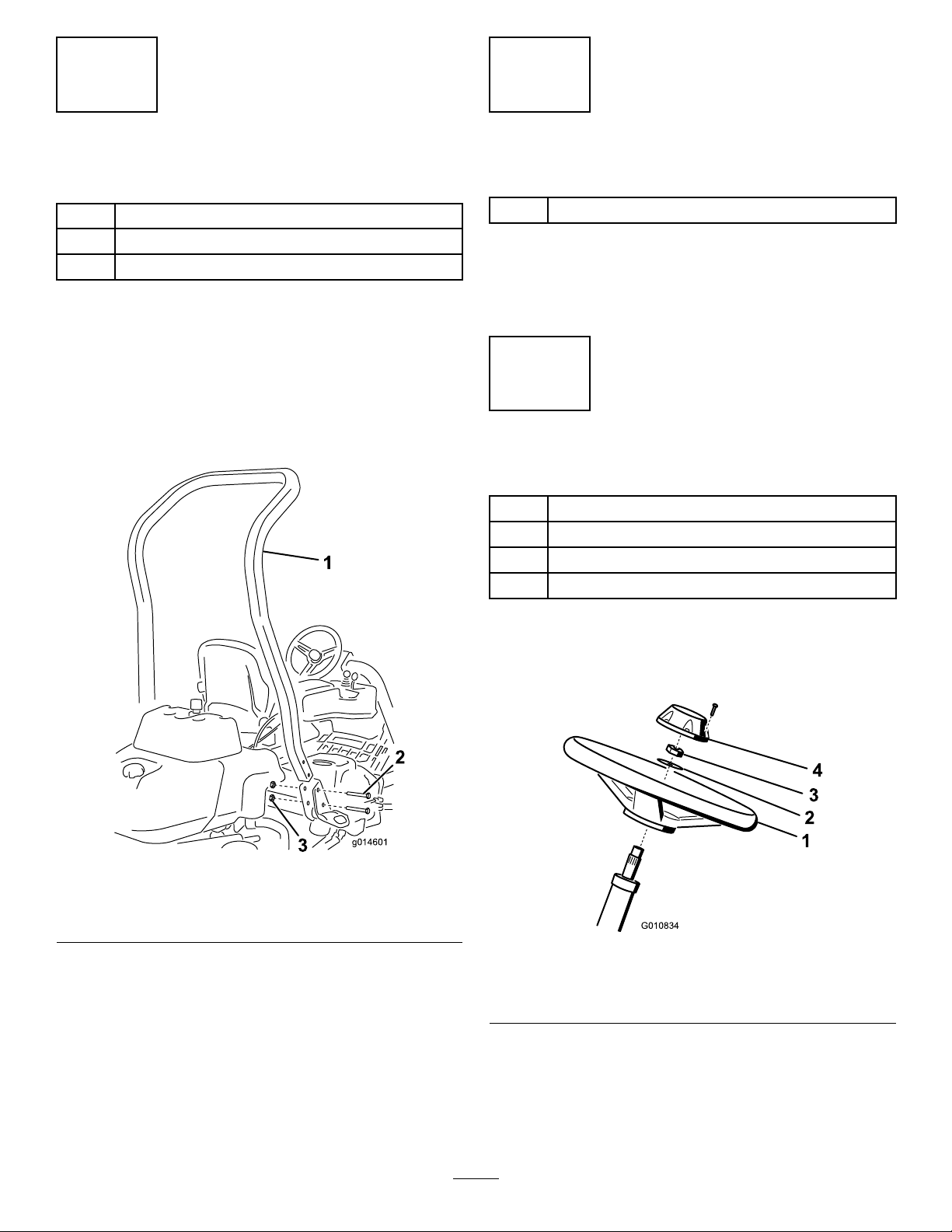
InstallingtheRollBar
Partsneededforthisprocedure:
1Rollbar
4
Bolt(1/2x3-3/4inches)
4
Flange-nut(1/2inch)
Procedure
1.Removethetopcratesupportfromthecrate.
2.Removetherollbarfromthecrate.
3.Installtherollbarintothepocketsoneachsideof
themachine,using4bolts(1/2x3-3/4inches)and4
ange-nuts(1/2inch)(Figure3).
InstallingtheSeat
Partsneededforthisprocedure:
1
Seat-completionkit
Procedure
Acquireyourdesiredseatkitfromyourdistributorandinstall
itasdirectedintheinstructionincludedwiththekit.
3
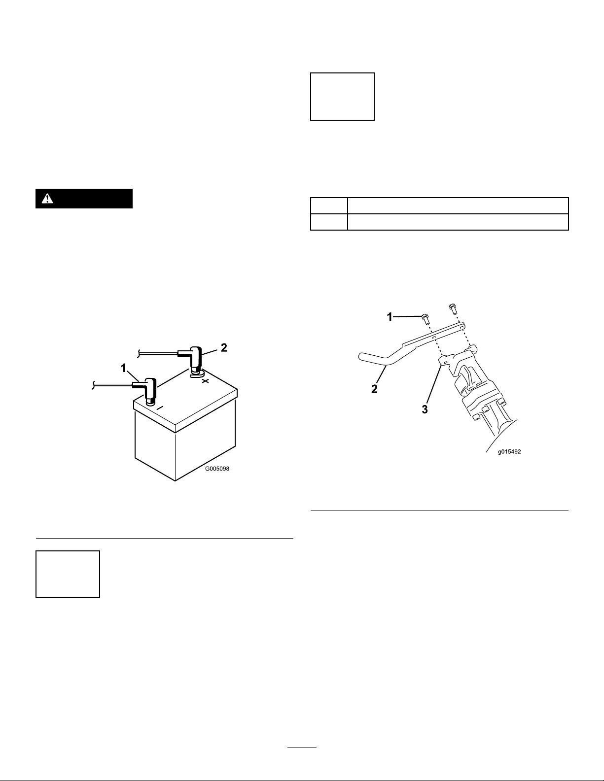
InstallingtheSteeringWheel
Partsneededforthisprocedure:
1
Steeringwheel
1
Locknut(1-1/2inches)
1Washer
1
Steering-wheelcap
Figure3
1.Rollbar
2.Bolt(1/2x3-3/4inches)
4.Torquethefastenersto136to149N∙m(100to110
ft-lb).
3.Flange-nut(1/2inch)
Procedure
1.Slidethesteeringwheelontothesteeringshaft(Figure
4).
Figure4
1.Steeringwheel
2.Washer
2.Slidethewasherontothesteeringshaft(Figure4).
3.Securethesteeringwheeltotheshaftwithalocknut
andtightenitto27to35N∙m(20to26ft-lb)(Figure4).
4.Installthecaptothesteeringwheelandsecureitwith6
bolts(Figure4).
3.Locknut
4.Cap
12
Page 13
4
ActivatingandChargingthe
Battery
NoPartsRequired
Procedure
Useonlyelectrolyte(1.265specicgravity)tollthebattery
initially.
WARNING
CALIFORNIA
Proposition65Warning
Batteryposts,terminals,andrelated
accessoriescontainleadandleadcompounds,
chemicalsknowntotheStateofCalifornia
tocausecancerandreproductiveharm.
Washhandsafterhandling.
1.Removethefastenersandbatteryclampandliftout
thebattery.
Important:Donotaddelectrolytewhilethe
batteryisinthemachine.Y oucouldspillit,
causingcorrosion.
2.Cleanthetopofthebatteryandremovetheventcaps
(Figure5).
Figure6
1.Electrolyte
4.Allowapproximately20to30minutesforthe
electrolytetosoakintotheplates.Fillasnecessaryto
bringtheelectrolytetowithinabout6mm(1/4inch)
ofthebottomofthellwell(Figure6).
5.Connecta2to4Abatterychargertothebatteryposts.
Chargethebatteryforatleast2hoursat4Aorforat
least4hoursat2Auntilthespecicgravityis1.250
orhigherandthetemperatureisatleast16°C(60°F)
withallcellsgassingfreely .
WARNING
Chargingthebatteryproducesgassesthatcan
explode.
Neversmokenearthebatteryandkeepsparks
andamesawayfromthebattery.
Important:Ifyoudonotchargethebatteryforat
leastthetimespeciedabove,youmayreducethe
lifeofthebattery.
6.Whenthebatteryischarged,disconnectthecharger
fromtheelectricaloutletandbatteryposts.
Figure5
3.Carefullylleachcellwithelectrolyteuntiltheplates
arecoveredwithabout6mm(1/4inch)ofuid(Figure
6).
Note:Afterthebatteryhasbeenactivated,add
onlydistilledwatertoreplacenormalloss,although
maintenance-freebatteriesshouldnotrequirewater
undernormaloperatingconditions.
WARNING
Batteryterminalsormetaltoolscouldshort
againstmetaltractorcomponentscausing
sparks.Sparkscancausethebatterygassesto
explode,resultinginpersonalinjury.
•Whenremovingorinstallingthebattery,
donotallowthebatteryterminalstotouch
anymetalpartsofthetractor.
•Donotallowmetaltoolstoshortbetween
thebatteryterminalsandmetalpartsof
thetractor.
13
Page 14
Important:Failuretocorrectlyactivatethe
batterymayresultinbatterygassingand/or
prematurebatteryfailure.
7.Installtheventcaps.
8.Placethebatteryonthebatterytrayandsecureitwith
thebatteryclampandfastenersremovedpreviously.
9.Installthepositivecable(red)tothepositive(+)
terminalandthenthenegativecable(black)tothe
negative(–)terminalofthebatteryandsecurethem
withtheboltsandnuts(Figure7).Slidetherubber
bootoverthepositiveterminaltopreventapossible
shortfromoccurring.
WARNING
Incorrectbatterycableroutingcoulddamagethe
tractorandcablescausingsparks.Sparkscancause
thebatterygassestoexplode,resultinginpersonal
injury.
•Alwaysdisconnectthenegative(black)battery
cablebeforedisconnectingthepositive(red)
cable.
•Alwaysconnectthepositive(red)batterycable
beforeconnectingthenegative(black)cable.
heavy-dutyuse(mowingotherthangreens,suchasfairways
orverticutting),installaHydraulicOilCoolerKit,PartNo.
119-1691.
6
InstallingtheGrass-Basket Hooks
Partsneededforthisprocedure:
6
Grass-baskethook
12Flangebolts
Procedure
Installthe6grass-baskethooksontotheendsofthe
suspension-armbarsusingthe12angebolts(Figure8).
Figure7
1.Negative(-)
2.Positive(+)
5
InstallingtheOilCooler (optional)
NoPartsRequired
Procedure
Ifyouareoperatingthemachineinhotclimates,wherethe
ambienttemperatureisabove29°C(85°F),orusingitfor
1.Flangebolt
2.Grass-baskethook
Figure8
3.Suspension-armbar
14
Page 15

7
10
InstallingtheCuttingUnits
Partsneededforthisprocedure:
1
Gaugebar
3
Cuttingunit(obtainfromyourT oroDistributor)
3
Grassbasket
Procedure
1.Setupthecuttingunitsasdescribedinthecuttingunit
Operator’sManual.
2.Applygreasetotheinsidediameterofthedrivecoupler.
3.InstallthecuttingunitsasdescribedinInstallingthe
CuttingUnits(page27).
8
AddingRearWeight
Partsneededforthisprocedure:
WeightKit,121-6665(purchaseseparately)Note:
1
Thiskitisnotrequiredforunitswiththe3wheeldrive
kitinstalled.
ReducingtheTirePressure
NoPartsRequired
Procedure
Thetiresareover-inatedatthefactoryforshipping
purposes.Reducethepressuretotheproperlevelsbefore
startingthemachine.RefertoCheckingtheTirePressure
(page25).
11
BurnishingtheBrakes
NoPartsRequired
Procedure
Firmlyapplythebrakesanddrivethemachineatmowing
speeduntilthebrakesarehot,asindicatedbytheirsmell.Y ou
mayneedtoadjustthebrakesafterthebreak-inperiod;refer
toAdjustingtheBrakes(page42).
Procedure
ThisunitcomplieswithENISO5395:2013andANSI
B71.4-2012whenequippedwithWeightKit,PartNo.
121-6665.
Note:Iftheunitisequippedwitha3-WheelDriveKit,
additionalweightisnotrequiredtomeetENISO5395:2013
andANSIB71.4-2012.
9
InstallingEUDecals
Partsneededforthisprocedure:
1Warningdecal,133-2338
Procedure
IfthismachinewillbeusedintheEU ,afxthewarning-decal
133-2338overEnglishwarning-decal133-2339.
15
Page 16

ProductOverview
g014674
1
2
3
4
5
6
7
8
g014603
1
2
3
Figure10
Figure9
1.Engine
2.Rollbar6.Tractionpedal
3.Controlpanel
4.Seat
5.Steeringwheel
7.Footrest
8.Reelswithgrassbaskets
1.Tractionpedal—forward3.Steering-arm-locking
2.Tactionpedal—reverse
pedal
Controls
TractionPedal
Thetractionpedal(Figure10)has3functions:tomakethe
machinemoveforward,tomoveitbackward,andtostopthe
machine.Pressthetopofthepedaltomoveforwardandthe
bottomofthepedaltomovebackwardortoassistinstopping
whenmovingforward.Also,allowthepedaltomovetothe
neutralpositiontostopthemachine.Foroperatorcomfort,
donotresttheheelofyourfootonreversewhenoperating
forward(Figure11).
Groundspeedsareasfollows:
•3.2to8km/h(2to5mph)forwardmowingspeed
•16km/h(10mph)maximumtransportspeed
•4.0km/h(2.5mph)reversespeed
Steering-Arm-LockingPedal
Pressthepedal(Figure10)andraiseorlowerthesteering
armforoperatorcomfort,then,releasethepedaltolockthe
arminplace.
Figure11
ThrottleLever
Thethrottlelever(Figure12)allowsyoutocontrolthespeed
oftheengine.MovethethrottlelevertowardtheFAST
positiontoincreasestheenginespeed;moveittowardthe
SLOWpositiontodecreasetheenginespeed.
Note:Youcannotstoptheenginecannotusingthethrottle
lever.
16
Page 17

Engine-Oil-PressureLight
g014600
1
Thelight(Figure12)glowsiftheengineoilpressuredrops
belowasafelevel.
Water-TemperatureLight
Thelight(Figure12)glowsandtheengineautomaticallyshuts
downwhentheengine-coolanttemperaturegetstoohigh.If
theengineshutsdown,youcanstarttheengineanddrive
themachinefor10secondsbeforeitwillshutdownagain,
allowingyoutomovethemachinetoalocationwhereyou
canallowittocooldown.
Service-IndicatorLight
Figure12
1.Throttlelever6.Battery-warninglight
2.Raise/Lowermowcontrol7.Service-indicatorlight
3.Functional-controllever
4.Ignitionswitch9.Water-temperaturelight
5.Engine-oil-pressurelight
8.Glow-plug-indicatorlight
Raise/LowerMowControl
Movingthecontrol(Figure12)forwardduringoperation
lowersthecuttingunitsandstartsthereels.Pullbackonthe
controltostopthereelsandraisethecuttingunits.During
operationthereelscanbestoppedbypullingbackonthe
controlmomentarilyandreleasingit.Startthereelsby
movingthecontrolforward.
FunctionalControlLever
Thefunctionalcontrollever(Figure12)provides2traction
selectionsplusaNEUTRALposition.Itispermissibletoshift
frommowtotransportortransporttomow(nottoneutral)
whilethemachineisinmotion.Nodamagewillresult.
Theservice-indicatorlight(Figure12)illuminateswhenthe
machinesensorsdetectanissuewithoneofthesystems
ofthemachine.Ifthislightilluminates,stopwhatyouare
doinganddrivetoasafelocationwhereyouoraservice
techniciancandiagnosetheproblem.Formoreinformation
ondiagnosingsystemissuesusingtheservice-indicatorlight,
refertoDiagnosingtheServiceIndicatorLight(page45).
Glow-Plug-IndicatorLight
Whentheglow-plug-indicatorlight(Figure12)islit,it
indicatestheglowplugsareon.
Note:Theglow-plug-indicatorlightmayilluminatefora
shorttimeaftertheenginehasstarted;thisisnormal.
HourMeter
Thehourmeter(Figure13)indicatesthetotalhoursthe
machinehasoperated.Itstartstofunctionwheneveryou
rotatetheignitionswitchtotheONposition.
•REARPosition—neutralandbacklapping
•MIDDLEPosition—usedformowingoperation
•FRONTPosition—usedfortransportoperation
IgnitionSwitch
Insertthekeyintotheswitch(Figure12)andturnitclockwise
asfaraspossibletotheSTARTpositiontostarttheengine.
Releasethekeyassoonastheenginestarts;thekeywillmove
totheONposition.Turnthekeycounterclockwisetothe
OFFpositiontostoptheengine.
Battery-WarningLight
Thelight(Figure12)glowsifthebatterychargeislow .
Figure13
1.Hourmeter
17
Page 18

Parking-BrakeLever
g014620
1
2
g014623
1
g014628
1
Pulluponthebrakelever(Figure14)tosettheparkingbrake.
Disengageitbypullinguponthereleaselatchandlowering
thebrakehandle.Locktheparkingbrakeanytimeyouleave
themachine.
Figure16
1.Reel-speedcontrol
Figure14
1.Parking-brakelever2.Releaselatch
BacklapLever
Thebacklapleverislocatedundertheplasticcovertotheleft
oftheseat.Usethebacklaplever(Figure15)inconjunction
withtheraise/lowermowcontrolleverandthereelspeed
controlforbacklappingthereels.
Figure15
Seat-AdjustingLever
Theseat-adjustingleverislocatedonthefront,rightcorner
oftheseat(Figure17),allowingyoutoadjusttheseatfore
andaft.
Note:Ifyouneedadditionaladjustmentontheseat,youcan
removethefourboltssecuringtheseattothebaseandmove
theseattothesecondsetofmountingholesprovided.
1.Backlaplever—mow
position
2.Backlaplever—backlap
position
Reel-SpeedControl
Thereel–speedcontrolislocatedundertheplasticcoverto
theleftoftheseat.Usethereel-speedcontrol(Figure16)to
adjusttherpmofthereels.
Figure17
1.Seat-adjustinghandle
18
Page 19

Fuel-ShutoffValve
g01462 6
1
Specications
Closethefuel-shutoffvalve(Figure18),behindtheseatand
underthefueltank,whenstoringortransportingthemachine
onatruckortrailer.
Figure18
1.Fuelshutoff(underthefueltank)
Note:Specicationsanddesignaresubjecttochange
withoutnotice.
Widthofcut151cm(59.5inches)
Wheeltread
Wheelbase
Overalllength(w/baskets)249cm(98inches)
Overallwidth179cm(70.5inches)
Overallheight205cm(81inches)
NetWeightw/reels(11Blade)696kg(1,535lb)
128cm(50.5inches)
123cm(48.5inches)
Attachments/Accessories
AselectionofToroapprovedattachmentsandaccessoriesis
availableforusewiththemachinetoenhanceandexpand
itscapabilities.ContactyourAuthorizedServiceDealeror
Distributororgotowww .Toro.comforalistofallapproved
attachmentsandaccessories.
Tobestprotectyourinvestmentandmaintainoptimal
performanceofyourToroequipment,countonTorogenuine
parts.Whenitcomestoreliability ,Torodeliversreplacement
partsdesignedtotheexactengineeringspecicationofour
equipment.Forpeaceofmind,insistonT orogenuineparts.
19
Page 20

Operation
G009027
1
2
Usehigh-qualityengineoilthatmeetsthefollowing
specications:
Note:Determinetheleftandrightsidesofthemachine
fromthenormaloperatingposition.
ThinkSafetyFirst
Carefullyreadallsafetyinstructionsandsymbolsinthe
safetysection.Knowingthisinformationcouldhelpyouor
bystandersavoidinjury.
DANGER
Operatingthemachineonwetgrassorsteepslopes
cancauseslidingandlossofcontrol.
•Reducespeedanduseextremecautionon
slopes.
•Donotoperatethemachinenearwater.
DANGER
Wheelsdroppingoveredgescancauserollovers,
whichmayresultinseriousinjury,death,or
drowning.
Donotoperatethemachineneardrop-offs.
•APIClassicationLevelRequired:CH–4,CI–4orhigher.
•Preferredoil:SAE10W–30
•Alternateoil:SAE15W–40
ToroPremiumEngineoilisavailablefromyourdistributorin
the10W–30viscosity .Seethepartscatalogforpartnumbers.
Note:Thebesttimetochecktheengineoiliswhenthe
engineiscoolbeforeithasbeenstartedfortheday.Ifithas
alreadybeenrun,allowtheoiltodrainbackdowntothe
sumpforatleast10minutesbeforechecking.Iftheoillevel
isatorbelowtheAddmarkonthedipstick,addoiltobring
theoilleveltotheFULLmark.Donotoverll.
Important:Keeptheengineoillevelbetweentheupper
andlowerlimitsontheoilgauge;theenginemayfailif
yourunitwithtoomuchortoolittleoil.
1.Positionthemachineonalevelsurface.
2.Removethedipstickandwipeitwithacleanrag
(Figure21).
Important:Removethedipstickwhilellingthe
enginewithoil.Whenaddingengineoilorlling
oil,there
deviceandtheoilllholeinthevalvecoveras
showninFigure20.Thisclearanceisnecessary
topermitventingwhenlling,whichpreventsoil
fromoverrunningintobreather.
must be
clearancebetweentheoilll
CAUTION
Thismachineproducessoundlevelsthatcancause
hearinglossthroughextendedperiodsofexposure.
Wearhearingprotectionwhenoperatingthis
machine.
Useprotectiveequipmentforeyes,ears,hands,feet,andhead.
Figure19
1.Weareyeprotection.2.Wearhearingprotection.
CheckingtheEngineOil
ServiceInterval:Beforeeachuseordaily
Figure20
1.Noteclearance
Theengineisshippedwith3.7L(3.9USqt)(w/lter)ofoil
inthecrankcase;however,youmustchecktheoillevelbefore
andafterstartingtheenginethersttime.
20
Page 21

g014618
1
2
Figure21
1.Fillercap2.Dipstick
DANGER
Undercertainconditions,dieselfuelandfuel
vaporsarehighlyammableandexplosive.Are
orexplosionfromfuelcanburnyouandothersand
cancausepropertydamage.
•Useafunnelandllthefueltankoutdoors,in
anopenarea,whentheengineisoffandiscold.
Wipeupanyfuelthatspills.
•Donotllthefueltankcompletelyfull.Add
fueltothefueltankuntilthelevelis6to13mm
(1/4to1/2inch)belowthebottomoftheller
neck.Thisemptyspaceinthetankallowsthe
fueltoexpand.
•Neversmokewhenhandlingfuel,andstayaway
fromanopenameorwherefuelfumesmaybe
ignitedbyaspark.
3.Pushthedipstickintothetubeandmakesureitis
seatedfully.
4.Removethedipstickfromthetubeandcheckthelevel
ofoil.
Note:Iftheoillevelislow,removethellercapfrom
thevalvecoverandslowlyaddenoughoiltoraisethe
leveltotheFULLmarkonthedipstick.
Addtheoilslowlyandchecktheleveloftenduringthis
process.Donotoverll.
5.Replacethedipstick.
6.Startandruntheengineatidlefor30seconds,then
shuttheengineoff.Wait30seconds,thenrepeatsteps
2through5.
7.Installthellercapanddipstickrmlyinplace.
FillingtheFuelTank
Useonlyclean,freshdieselfuelorbiodieselfuelswithlow
(<500ppm)orultralow(<15ppm)sulfurcontent.The
minimumcetaneratingshouldbe40.Purchasefuelin
quantitiesthatcanbeusedwithin180daystoensurefuel
freshness.
•Storefuelinaclean,sealed,safety-approved
container.
Fueltankcapacity:22.7L(6U.S.gallons)
Usesummergradedieselfuel(No.2-D)attemperatures
above-7°C(20°F)andwintergrade(No.1-DorNo.
1-D/2-Dblend)belowthattemperature.Useofwintergrade
fuelatlowertemperaturesprovideslowerashpointand
coldowcharacteristicswhichwilleasestartingandreduce
fuellterplugging.
Useofsummergradefuelabove-7°C(20°F)willcontribute
towardlongerfuelpumplifeandincreasedpowercompared
towintergradefuel.
21
Page 22

DANGER
g014612
1
Incertainconditions,fuelisextremelyammable
andhighlyexplosive.Areorexplosionfromfuel
canburnyouandothersandcandamageproperty.
•Fillthefueltankoutdoors,inanopenarea,when
theengineiscold.Wipeupanyfuelthatspills.
•Donotllthefueltankcompletelyfull.Addfuel
tothefueltankuntilthelevelis25mm(1inch)
belowthebottomofthellerneck.Thisempty
spaceinthetankallowsfueltoexpand.
•Neversmokewhenhandlingfuel,andstayaway
fromanopenameorwherefuelfumesmaybe
ignitedbyaspark.
•Storefuelinanapprovedcontainerandkeepit
outofthereachofchildren.Neverbuymore
thana30-daysupplyoffuel.
•Alwaysplacefuelcontainersonthegroundaway
fromyourvehiclebeforelling
•Donotllfuelcontainersinsideavehicleoron
atruckortrailerbedbecauseinteriorcarpets
orplastictruckbedlinersmayinsulatethe
containerandslowthelossofanystaticcharge.
•Whenpractical,removethemachinefromthe
truckortrailerandrefuelitwithitswheelson
theground.
•Ifthisisnotpossible,thenrefuelsuchequipment
onatruckortrailerfromaportablecontainer,
ratherthanfromafueldispensernozzle.
•Ifafueldispensernozzlemustbeused,keepthe
nozzleincontactwiththerimofthefueltank
orcontaineropeningatalltimesuntilfuelingis
complete.
1.Cleanaroundthefuel-tankcap(Figure22).
Figure22
1.Fuel-tankcap
2.Removethefuel-tankcap.
3.Fillthetankuntilthelevelis6to13mm(1/4to1/2
inch)belowthebottomofthellerneck.
Important:Donotoverll.
4.Installthecap.
5.Wipeupanyfuelthatmayhavespilled.
UsingBiodieselFuel
Thismachinecanalsouseabiodieselblendedfuelofup
toB20(20%biodiesel,80%petrodiesel).Thepetrodiesel
portionshouldbeloworultralowsulfur.Observethe
followingprecautions:
•Thebiodieselportionofthefuelmustmeetspecication
ASTMD6751orEN14214.
•TheblendedfuelcompositionshouldmeetASTMD975
orEN590.
•Paintedsurfacesmaybedamagedbybiodieselblends.
•UseB5(biodieselcontentof5%)orlesserblendsincold
weather
•Monitorseals,hoses,gasketsincontactwithfuelasthey
maybedegradedovertime.
•Fuellterpluggingmaybeexpectedforatimeafter
convertingtobiodieselblends.
•Contactyourdistributorifyouwishformoreinformation
onbiodiesel
22
Page 23

CheckingtheCoolingSystem
g01461 3
1
2
3
4
Thecapacityofthecoolingsystemisapproximately4.6L
(4.9USqt).Keeptheradiatorscreenclean;refertoCleaning
theRadiatorScreen(page41).
Figure24
1.Reservetank
3.Ifthecoolantislow,removethereservetankcapand
adda50/50mixtureofwaterandpermanentethylene
glycolantifreeze.Donotoverll.
Figure23
1.Wingbolts3.Reservetank
2.Radiatorscreen
Fillthecoolingsystemwitha50/50solutionofwaterand
permanentethyleneglycolantifreeze.Checkthelevelof
thecoolantatthebeginningofeachdaybeforestartingthe
engine.
4.Radiatorllcap
CAUTION
Iftheenginehasbeenrunning,thepressurized,hot
coolantcanescapeandcauseburns.
•Donotopentheradiatorcapwhentheengine
isrunning.
•Usearagwhenopeningtheradiatorcap,and
openthecapslowlytoallowsteamtoescape.
1.Parkthemachineonalevelsurface.
2.Checkthecoolantlevel(Figure24).
4.Installthereserve-tankcap.
CheckingtheHydraulic-Fluid Level
Thehydraulic-uidreservoirislledatthefactorywith
approximately20.8L(5.5USgallons)ofhighqualityhydraulic
uid.Beforeoperatingthemachineeachday,checklevelof
thehydraulicuidinthewhiteplasticwindowonthefrontof
thehydraulic-uidreservoir(behindtheseatontheleftside).
Theuidshouldbebetweenthelinesinthewindow;ifnot,
addanappropriateuidasdescribedinthefollowingsections:
Therecommendedreplacementuidisasfollows:
ToroPremiumAllSeasonHydraulicFluid(Availablein
5-gallonpailsor55-gallondrums.Seepartscatalogor
Torodistributorforpartnumbers.)
Alternateuids:IftheTorouidisnotavailable,otheruids
maybeusedprovidedtheymeetallthefollowingmaterial
propertiesandindustryspecications.W edonotrecommend
theuseofsyntheticuid.Consultwithyourlubricant
distributortoidentifyasatisfactoryproduct
Note:Itshouldbebetweenthelinesonthereserve
tankwhentheengineiscold.
Note:Torowillnotassumeresponsibilityfordamage
causedbyimpropersubstitutions,souseonlyproducts
fromreputablemanufacturerswhowillstandbehindtheir
recommendation.
23
Page 24

HighViscosityIndex/LowPourPointAnti-wearHydraulic
g014719
1
g014720
1
2
Fluid,ISOVG46
MaterialProperties:
Viscosity,ASTMD445cSt@40°C44to48
ViscosityIndexASTMD2270
PourPoint,ASTMD97-34°Fto-49°F
IndustrySpecications:
VickersI-286-S(QualityLevel),VickersM-2950-S
(QualityLevel),DenisonHF-0
cSt@100°C7.9to8.5
140to160
Important:TheISOVG46Multigradeuidhasbeen
foundtoofferoptimalperformanceinawiderangeof
temperatureconditions.Foroperationinconsistently
highambienttemperatures,18°C(65°F)to49°C
(120°F),ISOVG68hydraulicuidmayofferimproved
performance.
PremiumBiodegradableHydraulicFluid-MobilEAL
EnviroSyn46H
Important:MobilEALEnviroSyn46Histheonly
syntheticbiodegradableuidapprovedbyT oro.This
uidiscompatiblewiththeelastomersusedinToro
hydraulicsystemsandissuitableforawide-range
oftemperatureconditions.Thisuidiscompatible
withconventionalmineraloils,butformaximum
biodegradabilityandperformancethehydraulicsystem
shouldbethoroughlyushedofconventionaluid.The
oilisavailablein19L(5gallon)containersor55gallon
drumsfromyourMobilDistributor.
Important:Manyhydraulicuidsarealmostcolorless,
makingitdifculttospotleaks.Areddyeadditive
forthehydraulicsystemoilisavailablein20ml(2/3
oz)bottles.Onebottleissufcientfor15-22L(4-6
gallons)ofhydraulicuid.OrderPartNo.44-2500from
yourauthorizedTorodistributor.
T his r ed dy e is not
r ecommended f or use with biodeg rada ble uids.
Important:Regardlessofhydraulicuidtypeused,any
machineusedformowingfairways,verticuttingorused
duringambienttemperaturesabove29°C(85°F)should
haveOilCoolerKit,PartNo.117-9314,installed.
Figure25
1.Hydraulic-reservoircap
3.Slowlyllthereservoirwiththeappropriatehydraulic
uiduntilthelevelreachestheFullmarkinthewhite
windowinthefrontofthereservoir.Donotoverll.
Important:Topreventsystemcontamination,
cleanthetopofthehydraulicuidcontainers
beforepuncturing .Ensurethatthepourspoutand
funnelareclean.
4.Installthereservoircapandwipeupanyuidthatmay
havespilled.
Important:Checklevelofhydraulicuidbefore
engineisrststartedanddailythereafter.
DrainingWaterfromtheFuel Filter
ServiceInterval:Beforeeachuseordaily
1.Positionthemachineonalevelsurfaceandshutoff
theengine.
2.Placeadrainpanunderthefuellter.
3.Openthedrainplugonthefuellterapproximately
oneturnanddrainanyaccumulatedwater(Figure26).
FillingtheHydraulicTank
1.Positionthemachineonalevelsurface.
Note:Makesurethemachinehascooleddownso
theoiliscold.
2.Removethecapfromthereservoir(Figure25).
Figure26
1.Fuellter
24
2.Drainplug
Page 25

4.Tightentheplugafterdraining.
Note:Becausetheaccumulatedwaterwillbemixed
withdieselfuel,drainthefuellterintoasuitable
containeranddisposeofitproperly.
StartingandStoppingthe Engine
Note:Inspecttheareasbeneaththemowerstobecertain
theyareclearofdebris.
CheckingtheReel-to-Bedknife Contact
Eachdaybeforeoperatingthemachine,checkthe
reel-to-bedknifecontact,regardlessifthequalityofcuthad
previouslybeenacceptable.Theremustbelightcontact
acrossthefulllengthofthereelandbedknife;refertothe
CuttingUnitOperator’sManual.
CheckingtheTirePressure
Varythetirepressureforthefrontwheels,dependingupon
yourturfconditions,fromaminimumof83toamaximum
of110kPa(12psito16psi).
Varythetirepressurefortherearwheelfromaminimumof
83toamaximumof110kPa(12psito16psi).
CheckingtheTorqueofthe WheelNuts
WARNING
Failuretomaintainpropertorqueofthewheelnuts
couldresultinpersonalinjury.
StartingtheEngine
Important:Donotuseetherorothertypesofstarting
uid.
1.Sitontheseat,locktheparkingbrake,disengage
theraise/lowermowcontrolandmovethe
functional-controllevertotheNEUTRALposition.
2.Removeyourfootfromthetractionpedalandmake
surethepedalisintheNEUTRALposition.
3.MovethethrottlelevertotheSLOWposition.
4.Insertthekeyintotheswitchandrotateittothe
ONposition.HolditintheONpositionuntilthe
glow-plug-indicatorlightgoesoff(approximately6
seconds).
5.TurntheignitionkeytotheSTARTposition.
Important:Topreventoverheatingofthestarter
motor,donotengagethestarterlongerthan10
seconds.After10secondsofcontinuouscranking,
wait60secondsbeforeengagingthestartermotor
again.
6.Releasethekeywhentheenginestartsandallowitto
movetotheONposition.
7.MovethethrottlecontroltotheSLOWposition.
Torquethewheelnutsto95to122N∙m(70-90ft-lb)
after1-4hoursofoperationandagainafter10hours
ofoperation.Torqueevery200hoursthereafter.
Toensureevendistribution,torquethebrakesinastar
pattern.
BreakingintheMachine
Refertotheenginemanualsuppliedwiththemachineforoil
changeandmaintenanceproceduresrecommendedduring
thebreak-inperiod.
Only8hoursofmowingoperationisrequiredforthebreak-in
period.
Sincethersthoursofoperationarecriticaltofuture
dependabilityofthemachine,monitoritsfunctionsand
performancecloselysothatminordifculties,whichcould
leadtomajorproblems,arenotedandcanbecorrected.
Inspectthemachinefrequentlyduringbreak-inforsignsof
oilleakage,loosefasteners,oranyothermalfunction.
8.Allowtheenginetowarmupforafewminutesbefore
operating.
Important:Whenstartingtheenginefortherst
timeorafteranoverhauloftheengine,operate
themachineinforwardandreverseforoneto
twominutes.Turnthesteeringwheeltotheleft
andrighttocheckthesteeringresponse.Then
shuttheengineoff(seeStoppinginStartingand
StoppingtheEngine)andwaitforallmovingparts
tostop.Checkforoilleaks,loosepartsandany
othernoticeablemalfunctions.
StoppingtheEngine
1.MovethethrottlelevertotheSLOWposition,
disengagetheraise/lowermowcontrol,andmovethe
functional-controllevertotheNEUTRALposition.
2.RotatethestarterkeytotheOFFpositiontoshutthe
engineoff.Removethekeyfromtheswitchtoprevent
accidentalstarting.
3.Closethefuelshut-offvalvesbeforestoringthe
machine.
25
Page 26

CheckingtheSafetyInterlock
g014596
1
2
2
System
7.Sitontheseat,movethetractionpedaltotheNEUTRAL
position,movethefunctionalcontrollevertothe
NEUTRALposition,andengagetheparkingbrake.
CAUTION
Ifthesafetyinterlockswitchesaredisconnectedor
damagedthemachinecouldoperateunexpectedly
causingpersonalinjury.
•Donottamperwiththeinterlockswitches.
•Checktheoperationoftheinterlockswitches
dailyandreplaceanydamagedswitchesbefore
operatingthemachine.
Thepurposeofthesafety-interlocksystemistoprevent
operationofthemachinewherethereispossibleinjurytothe
operatorordamagetothemachine.
•ThetractionpedalisintheNEUTRALposition.
•Thefunctional-controlleverisintheNEUTRALposition.
Thesafety-interlocksystempreventsthemachinefrom
movingunless:
•Theparkingbrakeisoff.
•Theoperatorisseated.
•Thefunctional-controlleverisintheMOWpositionor
theTRANSPORTposition.
Thesafety-interlocksystempreventsthereelsfromoperating
unlessthefunctional-controlleverisintheMOWposition.
Performthefollowingsystemchecksdailytoensurethatthe
interlocksystemisoperatingcorrectly:
1.Sitontheseat,movethetractionpedaltotheNEUTRAL
position,movethefunctional-controllevertothe
NEUTRALposition,andengagetheparkingbrake.
2.Trytopressthetractionpedal.
Thepedalshouldnotpress,whichmeansthatthe
interlocksystemisoperatingcorrectly.Correctthe
problemifitisnotoperatingproperly.
3.Sitontheseat,movethetractionpedaltotheNEUTRAL
position,movethefunctional-controllevertothe
NEUTRALposition,andengagetheparkingbrake.
4.Movethefunctional-controllevertotheMOWposition
ortheTRANSPORTpositionandtrytostarttheengine.
8.Starttheengine.
9.Releasetheparkingbrake,movethefunctionalcontrol
levertotheMOWposition,andrisefromtheseat.
Theengineshouldshutoff,whichmeansthatthe
interlocksystemisoperatingcorrectly.Correctthe
problemifitisnotoperatingproperly.
10.Sitontheseat,movethetractionpedaltotheNEUTRAL
position,movethefunctionalcontrollevertothe
NEUTRALposition,andengagetheparkingbrake.
11.Starttheengine.
12.Movetheraise/lowermowcontrolforwardtolower
thecuttingunits.Thecuttingunitsshouldlowerbut
notstartrotating.
Iftheystartrotating,theinterlocksystemisnot
operatingcorrectly;correcttheproblembefore
operatingthemachine.
InstallingandRemovingthe CuttingUnits
Note:Whensharpening,settingtheheight-of-cut,or
performingothermaintenanceproceduresonthecutting
units,storethecuttingunitreelmotorsinthestoragelocation
onthefrontofthesuspensionarmstopreventdamageto
them.
Important:Donotraisethesuspensiontothetransport
positionwhenthereelmotorsareintheholdersinthe
machineframe.Damagetothemotorsorhosescould
result.
Important:Wheneveryouneedtotipthecuttingunit,
propuprearofcuttingunittoensurethatthenutson
thebedbaradjustingscrewsarenotrestingonwork
surface(Figure27).
Theengineshouldnotturn-overorstart,whichmeans
thattheinterlocksystemisoperatingcorrectly.Correct
theproblemifitisnotoperatingproperly.
5.Sitontheseat,movethetractionpedaltotheNEUTRAL
position,movethefunctional-controllevertothe
NEUTRALposition,andengagetheparkingbrake.
6.Starttheengineandmovethefunctional-controllever
totheMOWpositionortheTRANSPORTposition.
Theengineshouldkill,whichmeansthattheinterlock
systemisoperatingcorrectly.
Correcttheproblemifitisnotoperatingproperly.
Figure27
1.Prop(notprovided)
26
2.Bedbar-adjusting-screw
nut(2)
Page 27

InstallingtheCuttingUnits
g014602
1
2
g014609
1
2
3
g01461 1
1
2
1.Liftuponthefootrestandswingitopen,allowing
accesstothecentercuttingunitposition(Figure28).
CAUTION
Thefootrestcanpinchngersifitfallsinto
theclosedposition.
Keepyourngersclearoftheareawherethe
footrestseatswhileitisopen.
Figure30
1.Suspension-armbar2.Cutting-unitbar
Figure28
1.Footrest—closed2.Footrest—open
2.Positionthecuttingunitunderthecentersuspension
arm.
3.Withthelatchesonthesuspension-armbarpointing
up(i.e.,open)(Figure29),pushthesuspensionarm
downsothatthebartsoverthebaracrossthetopof
thecuttingunit(Figure30).
Figure29
1.Latch—closedposition3.Latch—openposition
2.Suspension-armbar
4.Closethelatchesdownandaroundthecutting-unitbar
andlocktheminplace(Figure29).
Note:A“click”canbeheardandfeltwhenthelatches
areproperlylockedinplace.
5.Coatthesplineshaftofthecuttingunitmotorwith
cleangrease(Figure31).
6.Insertthemotorintotheleftsideofthecuttingunit
(asviewedfromtheoperator'sposition)andpullthe
motorretainingbaronthecuttingunittowardthe
motoruntilyouhearanaudible“click”frombothsides
ofthemotor(Figure31).
27
Page 28

g014690
1
2
3
4
g014605
1
2
Figure32
g014608
1.Reelmotor2.Motor-retainingbar
3.Movethemotortothestoragelocationonthefrontof
thesuspensionarm(Figure33).
Figure31
1.Reelmotor
2.Splineshaft
3.Cavity
4.Motor-retainingbar
7.Mountagrassbasketontothebaskethooksonthe
suspensionarm.
8.Repeatthisprocedurefortheothercuttingunits.
RemovingtheCuttingUnits
1.Parkthemachineonacleanlevelsurface,lower
thecuttingunitstothegrounduntilthesuspension
hydraulicsarefullyextended,stoptheengine,andset
theparkingbrake.
2.Pushthemotorretainingbaroutoftheslotsonthe
motortowardsthecuttingunitandremovethemotor
fromthecuttingunit.
Figure33
Note:Whensharpening,settingtheheight-of-cut,
orperformingothermaintenanceproceduresonthe
cuttingunits,storethecuttingunitreelmotorsinthe
storagelocationonthefrontofthesuspensionarmsto
preventdamagetothem.
Important:Donotraisethesuspensiontothe
transportpositionwhenthereelmotorsareinthe
holdersinthemachineframe.Damagetothe
motorsorhosescouldresult.Ifyoumustmovethe
tractionunitwithoutthecuttingunitsinstalled,
securethemtothesuspensionarmsusingcable
ties.
4.Openthelatchesonthesuspension-armbarofthe
cuttingunityouareremoving(Figure29).
5.Disconnectthelatchesfromthecutting-unitbar.
6.Rollthecuttingunitoutfromunderthesuspension
arm.
7.Repeatsteps2through6fortheothercuttingunits
asrequired.
28
Page 29

SettingtheReelSpeed
g014736
g014623
1
Mowing
Toachieveaconsistent,high-qualitycutandauniform,
after-cutappearance,youmustcorrectlysetthereelspeed
control(locatedonthemanifoldblockunderthecovertothe
leftoftheseat).Adjustthereelspeedcontrolasfollows:
1.Selecttheheight-of-cutatwhichthecuttingunitsare
set.
2.Choosethedesiredgroundspeedbestsuitedfor
conditions.
3.Usingtheappropriategraph(SeeFigure34)for5,8,
11,or14bladecuttingunits,determinetheproperreel
speedsetting.
Beforemowinggreens,ndaclearareaandpracticestarting
andstoppingthemachine,raisingandloweringthecutting
units,turning,etc.
Inspectthegreenfordebris,removetheagfromthecup,
anddeterminethebestdirectiontomow .Basethedirection
tomowonthepreviousmowingdirection.Alwaysmowinan
alternatepatternfromthepreviousmowingsothatthegrass
bladeswillbelessapttolaydownandthereforebedifcult
totrapbetweenthereelbladesandthebedknife.
1.Approachthegreenwiththefunctional-controllever
intheMOWpositionandthethrottleatfullspeed.
2.Startononeedgeofthegreensothatyoucanusethe
ribbonprocedureofcutting.
Note:Thisholdscompactiontoaminimumand
leavesaneat,attractivepatternonthegreens.
3.Actuatetheraise/lowermowleverasthefrontedges
ofthegrassbasketscrosstheouteredgeofthegreen.
Note:Thisproceduredropsthecuttingunitstothe
turfandstartsthereels.
Important:TheNo.1cuttingunitreelisdelayed;
therefore,youshouldpracticetogaintherequired
timingnecessarytominimizethecleanupmowing
operation.
Figure34
4.Tosetthereelspeed,rotatetheknob(Figure35)
untiltheindicatorarrowsareinlinewiththenumber
designatingdesiredsetting.
Figure35
1.Reel-speedcontrol
4.Overlapaminimalamountwiththepreviouscuton
returnpasses.
Note:Toassistinmaintainingastraightlineacross
thegreenandkeepthemachineanequaldistancefrom
theedgeofthepreviouscut,establishanimaginary
sightlineapproximately1.8to3m(6to10ft)ahead
ofthemachinetotheedgeoftheuncutportionofthe
green(Figure36).Somenditusefultoincludethe
outeredgeofthesteeringwheelaspartofthesight
line;i.e.keepthesteeringwheeledgealignedwitha
pointthatisalwayskeptthesamedistanceawayfrom
thefrontofthemachine.
5.Asthefrontedgesofthebasketscrosstheedgeofthe
green,movetheraise/lowermowleverrearwardand
holdituntilallthecuttingunitshaverisen.Thiswill
stopthereelsandliftthecuttingunits.
Note:Itisimportanttotimethisstepcorrectlyso
thatyoudonotcutintothefringeareayetcutasmuch
ofthegreenaspossibletominimizetheamountof
grasslefttomowaroundtheouterperiphery.
6.Tocutdownonoperatingtimeandeaselineupfor
thenextpass,momentarilyturnthemachineinthe
oppositedirection,thenturnitinthedirectionofthe
uncutportion;i.e.,ifintendingtoturnright,rstswing
slightlyleft,thenright.
Note:Youcanincreaseordecreasethereelspeedto
compensateforturfconditions.
Note:Thiswillassistingettingthemachinemore
quicklyalignedforthenextpass.Trytomakeasshort
29
Page 30

ofaturnaspossibleexceptduringwarmerweather
whenawiderarcwillminimizetheturfbruising.
Figure36
Note:Heavywetclippingsplaceanunduestrainon
thebasketsandwilladdunnecessaryweighttothe
machine,therebyincreasingtheloadontheengine,
hydraulicsystem,brakes,etc.
InspectingandCleaningafter Mowing
Atthecompletionofthemowingoperation,thoroughlywash
themachinewithagardenhosewithoutanozzlesoexcessive
waterpressurewillnotcausecontaminationanddamageto
sealsandbearings.Neverwashawarmengineorelectrical
connectionswithwater.
Aftercleaning,inspectthemachineforpossiblehydraulic
uidleaks,damageorweartohydraulicandmechanical
components,andthecuttingunitsforsharpness.Also,
lubricatebrakeshaftassemblywithSAE30oilorspray
lubricanttodetercorrosionandhelpkeepthemachine
performingsatisfactorilyduringthenextmowingoperation.
1.Alignmentstrip
2.Approximately12.7cm(5
inches)
Note:Duetothenatureofthepowersteeringsystem,
thesteeringwheelwillnotreturntoitsoriginalposition
afteraturnhasbeencompleted.
Important:Neverstoponagreenwiththecutting
unitreelsoperatingasdamagetotheturfmay
result.Stoppingonawetgreenwiththemachine
mayleavemarksorindentationsfromthewheels.
7.Iftheleakdetectoralarmsoundswhilecuttingona
green,immediatelyraisethecuttingunits,drivedirectly
offthegreenandstopthemachineinanareaaway
fromthegreen.Determinethecauseofthealarmand
correcttheproblem.
8.Finishcuttingthegreenbymowingtheouterperiphery.
Besuretochangethedirectionofcuttingfromthe
previousmowing.
Note:Alwayskeepweatherandturfconditionsin
mindandbesuretochangethedirectionofmowing
fromthepreviouscutting.
9.Whennishedmowingtheouterperiphery,tapthe
raise/lowermowleverrearwardtostopthereels,then
driveoffthegreen.Whenallofthecuttingunitsare
offofthegreen,raisethem.
Note:Thiswillminimizegrassclumpsleftonthe
green.
10.Replacetheag.
11.Emptythegrassbasketsofallclippingsbefore
transportingtothenextgreen.
3.Cutgrassontheleft
4.Keepafocalspot2to3
m(6to10ft)aheadofthe
machine.
DrivingtheMachinewithout Mowing
Ensurethatthecuttingunitsarefullyraised.Movethe
functional-controllevertotheTRANSPORTposition.Use
thebrakestoslowthemachinewhilegoingdownsteep
hillstoavoidlossofcontrol.Alwaysapproachroughareas
atareducedspeedandcrosssevereundulationscarefully.
Familiarizeyourselfwiththewidthofthemachine.Donot
attempttopassbetweenobjectsthatareclosetogetherso
thatcostlydamageanddowntimecanbeprevented.
TransportingtheMachine
Useaheavy-dutytrailerortrucktotransportthemachine.
Ensurethatthetrailerortruckhasallnecessarybrakes,
lighting,andmarkingasrequiredbylaw .Readallthesafety
instructions.Knowingthisinformationcouldhelpyou,your
family,pets,orbystandersavoidinjury.
WARNING
Drivingonthestreetorroadwaywithoutturn
signals,lights,reectivemarkings,oraslow
movingvehicleemblemisdangerousandcanlead
toaccidentscausingpersonalinjury.
Donotdrivethemachineonapublicstreetor
roadway.
Useextremecautionwhenloadingthemachineontoatrailer
oratruck.Onefull-widthrampthatiswideenoughtoextend
beyondthereartiresisrequired(Figure37).
Therampshouldbelongenoughsothattheanglesdonot
exceed15degrees(Figure37).Asteeperanglemaycause
mowercomponentstogetcaughtastheunitmovesfromthe
ramptothetrailerortruck.Steeperanglesmayalsocause
30
Page 31

themachinetotipbackward.Ifloadingonornearaslope,
positionthetrailerortrucksothatitisonthedownside
oftheslopeandtherampextendsuptheslope.Thiswill
minimizetherampangle.Thetrailerortruckshouldbeas
levelaspossible.
Important:Donotattempttoturnthemachinewhile
ontheramp;youmaylosecontrolanddriveofftheside.
Avoidsuddenaccelerationwhendrivinguparampand
suddendecelerationwhenbackingdownaramp.Both
maneuverscancausethemachinetotipbackward.
WARNING
Loadingamachineontoatrailerortruckincreases
thepossibilityofbackwardtip-overandcouldcause
seriousinjuryordeath.
•Useextremecautionwhenoperatingamachine
onaramp.
Figure37
•Usetheseatbeltwhenloadingthemachine.
EnsurethattheROPSwillclearthetopofan
enclosedtrailer.
•Useonlyasingle,full-widthramp;donotuse
individualrampsforeachsideofthemachine.
•Ifindividualrampsmustbeused,useenough
rampstocreateanunbrokenrampsurfacewider
thanthemachine.
•Donotexceeda15-degreeanglebetweenthe
rampandthegroundorbetweentherampand
thetrailerortruck.
•Avoidsuddenaccelerationwhiledrivingthe
machineuparamp,toavoidtippingbackward.
•Avoidsuddendecelerationwhilebacking
themachinedownaramp,toavoidtipping
backward.
1.Trailer3.Notgreaterthan15
degrees
2.Full-widthramp4.Full-widthramp—side
view
1.Ifusingatrailer,connectittothetowingvehicleand
connectthesafetychains.
2.Ifapplicable,connectthetrailerbrakes.
3.Loadthemachineontothetrailerortruck.
4.Stoptheengine,removethekey ,settheparkingbrake,
andclosethefuelvalve.
5.Usethemetaltie-downloopsonthemachineto
securelyfastenthemachinetothetrailerortruckwith
straps,chains,cable,orropes.
TowingtheMachine
Incaseofanemergencythemachinecanbetowedforashort
distance(lessthan0.4km(1/4mile)).However,T orodoes
notrecommendthisasstandardprocedure.
Important:Donottowthemachinefasterthan3-5
km/h(2-3mph)becausethedrivesystemmaybe
damaged.Ifthemachinemustbemovedaconsiderable
distance,transportitonatruckortrailer.
1.Locatethebypassvalveonthepumpandrotateitso
thattheslotisvertical(Figure38).
31
Page 32

g014627
1
Figure38
1.Bypassvalve—slotshowninclosed(horizontal)position
2.Beforestartingtheengine,closethebypassvalveby
rotatingitsothattheslotishorizontal(Figure38).Do
notstarttheenginewhenthevalveisopen.
32
Page 33

Maintenance
Note:Determinetheleftandrightsidesofthemachinefromthenormaloperatingposition.
Note:Downloadafreecopyoftheelectricalorhydraulicschematicbyvisitingwww .Toro.comandsearchingforyour
machinefromtheManualslinkonthehomepage.
Important:Refertoyourengineoperator’smanualforadditionalmaintenanceprocedures.
CAUTION
Ifyouleavethekeyintheignitionswitch,someonecouldaccidentlystarttheengineandseriouslyinjure
youorotherbystanders.
Removethekeyfromtheignition.
RecommendedMaintenanceSchedule(s)
MaintenanceService
Interval
Afterthersthour
Aftertherst8hours
Aftertherst10hours
Aftertherst50hours
Beforeeachuseordaily
Every25hours
Every50hours
Every150hours
Every200hours
MaintenanceProcedure
•Checkthetorqueofthewheelnuts.
•Checkthetensiononthealternatorbelt.
•Checkthetorqueofthewheelnuts.
•Changetheengineoilandlter.
•Changethehydraulic-oillter.
•Checktheenginerpm(atidleandfullthrottle).
•Checktheengineoil.
•Cleandebrisoffoftheradiatorscreenandradiator.Cleanhourlyifconditionsare
extremelydustyanddirty.
•Checkthehydraulic-uidlevel.
•Drainwaterfromthefuellter.
•Checkthereel-to-bedknifecontact.
•Checkthehydrauliclinesandhoses.
•Checkthebatteryelectrolytelevel.(Ifthemachineisinstorage,checkevery30
days.)
•Checkthebatterycableconnections.
•Changetheengineoilandlter.
•Checkthetorqueofthewheelnuts.
•Servicetheair-cleanerlter(morefrequentlywhenoperatingconditionsaredusty
ordirty).
Every800hours
Every2years
•Replacethefuellter.
•Changethehydraulicuid,lter,andtankbreather.
•Checktheenginerpm(atidleandfullthrottle).
•Checkthevalveclearance.
•Checkthefuellinesandconnections.
•Replacemovinghoses.
•Drainandushthecoolingsystem.
33
Page 34

DailyMaintenanceChecklist
Duplicatethispageforroutineuse.
Fortheweekof: MaintenanceCheckItem
Checkthesafetyinterlock
operation.
Checktheinstrument
operation
Checkthebrakeoperation.
Checkthefuellter/water
separator.
Checkthefuellevel.
Checktheengineoillevel.
Cleanthescreenand
radiator.
Inspecttheairlter.
Checkanyunusualengine
noises.
Checkthereel-to-bedknife
adjustment.
Checkthehydraulichoses
fordamage.
Checkforuidleaks.
Checkthetirepressure.
Checktheheight-of-cut
adjustment.
Lubricatethetractionand
brakelinkage.
Touch-updamagedpaint.
Mon.Tues.Wed.Thurs.Fri.
Sat.Sun.
NotationforAreasofConcern
Inspectionperformedby:
ItemDate
Information
34
Page 35

EngineMaintenance
g014614
1
2
3
g014754
1
B.Carefullypulltheoldlteroutofthelterbody
anddiscardit.
ServicingtheAirCleaner
ServiceInterval:Every200hours
•Checktheair-cleanerbodyfordamagewhichcouldcause
anairleak;replaceitifitisdamaged.Checkthewhole
intakesystemforleaks,damage,orloosehoseclamps.
•Servicetheair-cleanerlterbefore200hoursifthe
engineperformancesuffersduetoextremelydusty,dirty
conditions.Changingtheairlterbeforeitisnecessary
onlyincreasesthechanceofdirtenteringtheenginewhen
thelterisremoved.
•Ensurethatthecoverisseatedcorrectlyandsealswith
theaircleanerbody.
1.Releasethelatchessecuringtheair-cleanercovertothe
air-cleanerbody(Figure39).
C.Insertthenewlterbyapplyingpressuretothe
outerrimoftheelementtoseatitinthecanister,
checkingthesealingendofthelterandthebody.
Important:Donotapplypressuretothe
exiblecenterofthelter.
5.Cleanthedirtejectionportlocatedintheremovable
cover.Removetherubberoutletvalvefromthecover,
cleanthecavityandreplacetheoutletvalve.
6.Installthecoverorientingtherubberoutletvalveina
downwardposition—betweenapproximately5:00to
7:00whenviewedfromtheend.
7.Securethelatches(Figure39).
ChangingtheEngineOiland Filter
ServiceInterval:Aftertherst50hours
Every150hours
1.Removethedrainplugandletoilowintoadrainpan.
Whentheoilstops,installthedrainplug(Figure40).
Figure39
1.Air-cleanerbody3.Air-cleanercover
2.Airlter
2.Removethecoverfromtheair-cleanerbody.
3.Beforeremovingthelter,uselowpressureair(40psi,
cleananddry)tohelpremovelargeaccumulationsof
debrispackedbetweentheoutsideoftheprimarylter
andthecanister.Thiscleaningprocesspreventsdebris
gettingintotheintakewhenyouremovetheprimary
lter.
Important:Avoidusinghighpressureairwhich
couldforcedirtthroughthelterintotheintake
tract.
4.Removeandreplacetheprimarylter,asfollows:.
Important:Donotcleantheusedelement.
A.Inspectthenewlterforshippingdamage;do
notuseadamagedelement.
Figure40
1.Drainplug
2.Removetheoillter(Figure41).Applyalightcoatof
cleanoiltothenewltergasket.
35
Page 36

g014615
1
Figure41
g01462 6
1
1.Oillter
3.Screwthelteronbyhanduntilthegasketcontacts
thelteradapter,thentighten1/2to3/4turnfurther.
Donotovertighten.
4.Addoiltothecrankcase;refertoCheckingtheEngine
Oil(page20).
FuelSystem
Maintenance
ReplacingtheFuelFilter/Water Separator
ServiceInterval:Every800hours
1.Closethefuel-shutoffvalve(Figure42)belowthefuel
tank.
5.Disposeoftheusedoilproperly.
Figure42
1.Fuel-shutoffvalve
2.Cleantheareawheretheltercanistermounts(Figure
43).
3.Placeadrainpanunderthefuellter.
4.Openthelterdrainplug(Figure43).
36
Page 37

g014720
1
2
1.Fuellter/waterseparator
canister
Figure43
2.Filter-drainplug
ElectricalSystem
Maintenance
ServicingtheBattery
WARNING
CALIFORNIA
Proposition65Warning
Batteryposts,terminals,andrelated
accessoriescontainleadandleadcompounds,
chemicalsknowntotheStateofCalifornia
tocausecancerandreproductiveharm.
Washhandsafterhandling.
5.Unscrewtheltercanisteranddisposeofitaccording
tolocalregulations.
6.Screwthelteronbyhanduntilthegasketcontactsthe
lteradapter,thentighten1/2to3/4turnfurther.
7.Ensurethatthelter-drainplugisclosed.Openthe
fuel-shutoffvalve.
InspectingtheFuelLinesand Connections
ServiceInterval:Every2years
Inspectthefuellinesfordeterioration,damage,orloose
connections.
Voltage:12v,530ColdCrankingAmps
Thebatteryelectrolytelevelmustbeproperlymaintainedand
thetopofthebatterykeptclean.lfthemachineisstoredina
locationwheretemperaturesareextremelyhigh,thebattery
willrundownmorerapidlythanifthemachineisstoredin
alocationwheretemperaturesarecool.
Maintainthecelllevelwithdistilledordemineralizedwater.
Donotllthecellsabovethebottomofthesplitringinside
eachcell.
DANGER
Batteryelectrolytecontainssulfuricacidwhichisa
deadlypoisonandcausessevereburns.
•Donotdrinkelectrolyteandavoidcontactwith
skin,eyesorclothing.Wearsafetyglassesto
shieldyoureyesandrubberglovestoprotect
yourhands.
•Fillthebatterywherecleanwaterisalways
availableforushingtheskin.
Keepthetopofthebatterycleanbywashingitperiodically
withabrushdippedinammoniaorbicarbonateofsoda
solution.Flushthetopsurfacewithwateraftercleaningit.
Donotremovethellcapswhilecleaningthebattery.
Thebatterycablesmustbetightontheterminalstoprovide
goodelectricalcontact.
37
Page 38

WARNING
g014617
1
2
LocatingtheFuses
Batteryterminalsormetaltoolscouldshortagainst
metaltractorcomponentscausingsparks.Sparks
cancausethebatterygassestoexplode,resulting
inpersonalinjury.
•Whenremovingorinstallingthebattery,donot
allowthebatteryterminalstotouchanymetal
partsofthetractor.
•Donotallowmetaltoolstoshortbetweenthe
batteryterminalsandmetalpartsofthetractor.
WARNING
Incorrectbatterycableroutingcoulddamagethe
tractorandcablescausingsparks.Sparkscancause
thebatterygassestoexplode,resultinginpersonal
injury.
Ifcorrosionoccursattheterminals,disconnect
thecables,negative(-)cablerst,andscrape
theclampsandterminalsseparately.Reconnect
thecables,positive(+)cablerst,andcoatthe
terminalswithpetroleumjelly.
Thefusesintheelectricalsystemarelocatedundertheseat
(Figure44).
Figure44
1.Fuses
2.50Afuseforradiatorfan
(behindpartsillustrated)
•Alwaysdisconnectthenegative(black)battery
cablebeforedisconnectingthepositive(red)
cable.
•Alwaysconnectthepositive(red)batterycable
beforeconnectingthenegative(black)cable.
StoringtheBattery
Ifthemachinewillbestoredmorethan30days,removethe
batteryandchargeitfully.Eitherstoreitontheshelfonthe
machine.Leavethecablesdisconnectedifitisstoredonthe
machine.Storethebatteryinacoolatmospheretoavoid
quickdeteriorationofthechargeinthebattery.Toprevent
thebatteryfromfreezing,makesureitisfullycharged.The
specicgravityofafullychargedbatteryis1.265–1.299.
FuseLayout
LiftReel
E-ReelEnable
OverTemp
7.5A
ReelEngage
Lights
LeakDetectorFan
15A7.5A
Starter
15A7.5A
Run
10A2A
Lift/Lower
Start/Run
Diag.Lights
Glow
ECMLogic
Power
38
Page 39

Jump-StartingtheMachine
g014616
1
2
DriveSystem
Ifyouneedtojumpstartthemachine,youcanusethe
alternate-positivepost(locatedonthestartersolenoid)instead
ofthepositivebatterypost(Figure45).
Figure45
1.Alternate-positivepost
Maintenance
AdjustingtheTransmission forNeutral
Ifthemachinecreepswhenthetraction-controlpedalisin
theNEUTRALposition,adjusttheneutral-returnmechanism.
1.Blockupundertheframesothatoneofthefront
wheelsisoffoftheoor.
Note:Ifmachineisequippedwitha3-WheelDrive
Kit,alsoraiseandblockrearwheel.
2.Starttheengine,movethethrottletotheSLOW
position,andensurethatthefrontwheelthatisoff
oftheoorisnotrotating.
3.Ifthewheelisrotating,shutofftheengineandproceed
asfollows:
A.Loosenthenutsecuringtheeccentrictothetop
ofthehydrostat(Figure46).
Figure46
1.Eccentric2.Locknut
B.Movethefunctional-controllevertotheNEUTRAL
positionandthethrottletotheSLOWposition.
Starttheengine.
C.Rotatetheeccentricuntilcreepdoesnotoccurin
eitherdirection.Whenthewheelstopsrotating,
tightenthenutlockingtheeccentricandthe
adjustment(Figure46).Verifytheadjustment
withthethrottleintheSLOWandFASTposition.
39
Page 40

Note:Ifthewheelstillturnswhentheeccentric
g015494
1
isatthemaximumadjustment,contactyour
AuthorizedServiceDistributororrefertothe
ServiceManualforfurtheradjustment.
AdjustingtheTransportSpeed
ObtainingtheMaximumTransport
Speed
Thetractionpedalisadjustedformaximum-transportspeed
atthefactory,butyoumayneedtoadjustitifthepedal
reachesfullstrokebeforeitcontactsthepedalstop,orifyou
wanttoadecreasethetransportspeed.
Toobtainthemaximum-transportspeed,putthefunctional
controlleverintheTRANSPORTpositionandpressdownon
thetractionpedal.Ifthepedalcontactsthestop(Figure47)
beforeyoufeeltensiononthecable,performthefollowing
adjustmentprocedure:
2.Loosenthepedalstopuntilyouobtainthedesired
transportspeed.
3.Tightenthelocknutsecuringthepedalstop.
Figure47
1.Pedalstop
1.Putthefunctional-controlleverintheTRANSPORT
positionandloosenthelocknutsecuringthepedalstop
totheoorplate(Figure47).
2.Tightenthepedalstopuntilitdoesnotcontactthe
tractionpedal.
3.Continueapplyingalightloadonthetransportpedal
andadjustthepedalstopsoitcontactsthepedalrod
andtightenthenuts.
Important:Ensurethatthetensiononthecable
isnotexcessiveoryouwillreducethecablelife.
ReducingtheTransportSpeed
1.Pressdownonthetractionpedalandloosenthe
locknutsecuringthepedalstoptotheoorplate.
40
Page 41

AdjustingtheMowingSpeed
g014625
1
2
3
g01461 3
1
2
3
4
CoolingSystem
Themowspeedissetto3.8mphatthefactory.
Theforwardmovingspeedcanbeadjustedfrom0to8km/h
(0to5mph).
1.Loosenthejamnutonthetrunnionbolt(Figure48).
2.Loosenthenutsecuringthelockandmowbrackets
onthepedalpivot.
Maintenance
CleaningtheRadiatorScreen
Topreventthesystemfromoverheating,keeptheradiator
screenandradiatorclean.Checkandcleanthescreenand
radiatordailyor,ifnecessary,hourly.Cleanthesecomponents
morefrequentlyindusty,dirtyconditions.
1.Removetheradiatorscreen(Figure49).
Figure48
1.Jamnut3.Trunnionbolt
2.Nut
3.Rotatethetrunnionboltclockwisetoreducethe
mowingspeedandcounterclockwisetoincreasethe
mowingspeed.
4.Tightenthejamnutonthetrunnionboltandthenut
onthepedalpivottolocktheadjustment(Figure48).
Checktheadjustmentandadjustasrequired.
Figure49
1.Wingbolts
2.Radiatorscreen4.Radiatorcap
2.Workingfromthefansideoftheradiator,blowoutthe
radiatorwithcompressedair.
3.Cleanthescreenandinstallit.
3.Overowtank
41
Page 42

BrakeMaintenance
g014755
1
2
3
BeltMaintenance
AdjustingtheBrakes
Ifthebrakefailstoholdthemachinewhileparked,youcan
adjustthebrakesusingthebulkheadttingnearthebrake
drum;contactyourAuthorizedServiceDistributororreferto
theServiceManualformoreinformation.
Note:Burnishthebrakesannually;referto11Burnishing
theBrakes(page15).
AdjustingtheAlternatorBelt
ServiceInterval:Aftertherst8hours
Ensurethatthebeltisproperlytensionedtoensureproper
operationofthemachineandpreventunnecessarywear.
1.Shutofftheengine,settheparkingbrake,andremove
theignitionkey.
2.Applymoderatethumbpressuretothebeltbetween
thepulleys(10kgor22lb).Thebeltshoulddeect7
to9mm(0.28to0.35inches).Ifnot,completethe
followingproceduretoadjustthebelttension:
Figure50
1.Alternatorbelt—applypressurehere
2.Alternator
3.Adjustingstrap
A.Loosentheboltssecuringthealternatortothe
engineandadjustingstrap.
B.Inspectthebeltforwearordamageandreplaceif
itisworn.
C.Usingaleverplacedbetweenthealternatorand
theengineblock,pullthealternatorouttoobtain
thecorrectbelttensionandtightenthebolts.
42
Page 43

HydraulicSystem
g014619
1
Maintenance
ChangingtheHydraulicFluid andFilter
ServiceInterval:Aftertherst50hours
Every800hours
Iftheoilbecomescontaminated,haveyourTorodistributor
ushthesystem.Contaminatedoillooksmilkyorblackwhen
comparedtocleanoil.
1.Cleantheareaaroundtheltermountingarea(Figure
51).Placeadrainpanunderthelterandremovethe
lter.
CheckingtheHydraulicLines andHoses
WARNING
Hydraulicuidescapingunderpressurecan
penetrateskinandcauseinjury.
•Makesureallhydraulicuidhosesandlinesare
ingoodconditionandallhydraulicconnections
andttingsaretightbeforeapplyingpressureto
thehydraulicsystem.
•Keepyourbodyandhandsawayfrompin
holeleaksornozzlesthatejecthighpressure
hydraulicuid.
•Usecardboardorpapertondhydraulicleaks.
•Safelyrelieveallpressureinthehydraulicsystem
beforeperforminganyworkonthehydraulic
system.
•Getimmediatemedicalhelpifuidisinjected
intoskin.
Figure51
1.Hydraulic-oillter
Note:Ifyouwillnotbedrainingtheoil,disconnect
andplugthehydrauliclinegoingtothelter.
2.Fillthereplacementlterwiththeappropriatehydraulic
uid,lubricatethesealinggasket,andhandturnituntil
thegasketcontactsthelterhead.Thentightenit3/4
turnfurther.
3.Fillthehydraulicreservoirwithhydraulicuid;referto
CheckingtheHydraulic-FluidLevel(page23).
Checkthehydrauliclinesandhosesdailyforleaks,kinked
lines,loosemountingsupports,wear,loosettings,weather
deterioration,andchemicaldeterioration.Makeallnecessary
repairsbeforeoperating.
4.Startthemachineandrunitatidlefor3to5minutes
tocirculatetheuidandremoveanyairtrappedinthe
system.Shutofftheengineandchecktheuidlevel.
5.Disposeoftheoilandlterproperly.
43
Page 44

CuttingUnitMaintenance
g014620
1
2
g014623
1
BacklappingtheReels
WARNING
Contactwiththereelsorothermovingpartscan
resultinpersonalinjury.
•Keepngers,hands,andclothingawayfromthe
reelsorothermovingparts.
•Neverattempttoturnthereelsbyhandorfoot
whiletheengineisrunning.
1.Positionthemachineonalevelsurface,lowerthe
cuttingunits,stoptheengine,andengagetheparking
brake.
2.Removetheplasticcovertotheleftsideoftheseat.
Figure53
1.Reel-speedcontrol
3.Makeinitialreeltobedknifeadjustmentsappropriate
forbacklappingonallcuttingunitswhicharetobe
backlapped;refertotheCuttingUnitOperator’ sManual.
DANGER
Changingtheenginespeedwhilebacklapping
maycausethereelstostall.
•Neverchangetheenginespeedwhile
backlapping.
•Onlybacklapatidleenginespeed.
4.Starttheengineandrunatlowidlespeed.
5.RotatethebacklaplevertotheREVERSE(R)position
(Figure52).
7.Withthefunctional-controlleverintheNEUTRAL
position,movetheraise/lowermowcontrolforwardto
startthebacklappingoperationonthedesignatedreels.
8.Applylappingcompoundwithalonghandlebrush.
Neveruseashorthandledbrush.
9.Ifthereelsstallorbecomeerraticwhilebacklapping,
selectahigherreelspeedsettinguntilthespeed
stabilizes,thenreturnthereelspeedtosetting1orto
yourdesiredspeed.
10.Tomakeanadjustmenttothecuttingunitswhile
backlapping,turnthereelsoffbymovingthe
raise/lowermowcontrolrearwardandstoptheengine.
Aftercompletingadjustments,repeatsteps4through8.
11.Repeattheprocedureforallcuttingunitsyouwantto
backlap.
12.Whennished,returnthebacklapleverstothe
FORWARD(F)position,replacethecover,andwash
alllappingcompoundoffofthecuttingunits.Adjust
cuttingunitreeltobedknifeasneeded.Movethe
cuttingunitreelspeedcontroltothedesiredmowing
position.
Figure52
1.Backlaplever—FORWARD
position
2.Backlaplever—REVERSE
position
6.Rotatethereel-speedcontroltosetting1(Figure53).
Important:Ifthebacklapleverisnotreturnedto
theFORWARD(F)positionafterbacklapping,the
cuttingunitswillnotraiseorfunctionproperly.
44
Page 45

DiagnosticsSystem
Storage
DiagnosingtheService IndicatorLight
Theserviceindicatorlightilluminatesintheeventofa
faultinthemachine.Whenthislightison,youcanaccess
thecomputercodestodiagnosetheproblembyentering
diagnosticmode.Indiagnosticmode,theserviceindicator
lightwillashanumberoftimesgivingyoutheerrorcode
thatyouoryourdistributorcanusetoidentifytheproblem.
Note:Theenginecannotbestartedindiagnosticmode.
EnteringDiagnosticMode
1.Stopthemachine,settheparkingbrake,andturnthe
ignitionkeytotheOFFposition.
2.Movethefunctional-controllevertotheTRANSPORT
position.
3.EnsurethatthebacklapleverissettotheFORWARD
(F)position.
4.Getoffoftheseat.
5.Holdtheraise/lowermowcontrolintheRAISED
position.
6.TurntheignitionswitchtotheRUNposition.
7.Countthecodesastheybegintoash(youmayrelease
theraise/lowermowcontroloncetheybeginashing).
Whennished,turnthekeytotheOFFpositiontoexit
diagnosticmode.
Ifyouwishtostorethemachineforalongperiodoftime,the
followingstepsshouldbeperformedpriortostorage:
1.Removeaccumulationsofdirtandoldgrassclippings.
Sharpenthereelsandbedknives,ifnecessary;referto
theCuttingUnitOperator'sManual.Usearustpreventive
onbedknivesandreelblades.Greaseandoilall
lubricationpoints.
2.Blockupthewheelstoremoveanyweightonthetires.
3.Drainandreplacethehydraulicuidandlterand
inspectthehydrauliclinesandttings.Replace,if
necessary;refertoChangingtheHydraulicFluidand
Filter(page43)andCheckingtheHydraulicLinesand
Hoses(page43).
4.Allfuelshouldberemovedfromthefueltank.Run
theengineuntilitstopsfromlackoffuel.Replacethe
fuellter;refertoReplacingtheFuelFilter/Water
Separator(page36).
5.Whiletheengineisstillwarm,draintheoilfromthe
crankcase.Rellitwithfreshoil;refertoChangingthe
EngineOilandFilter(page35).
6.Cleandirtandchafffromthecylinder,cylinderhead
ns,andblowerhousing.
7.Removethebatteryandchargeitfully.Eitherstore
itontheshelforonthemachine.Leavethecables
disconnectedifitisstoredonthemachine.Store
thebatteryinacoolatmospheretoavoidquick
deteriorationofthechargeinthebattery.
8.Ifpossible,storethemachineinawarm,drylocation.
DeterminingtheErrorCode
Thesystemwilldisplaythelast3faultsthatoccurredinthe
last40hours.Itdisplaysthefaultsthroughaseriesofblinking
lights,asfollows:
•Iftherearenofaults,thelightwithblinksteadilyata
mediumratewithoutpauses(1Hz).
•Ifthereisafault,itwillrstblinkthetensplace,followed
byapause,followedbytheonesplace.Forthefollowing
examples,a#representsablink.Examples:
–Ifthecodeis15,theblinkpatternwillbe#_#####
–Ifthecodeis42,theblinkpatternwillbe####_##
–Ifthecodeis123,theblinkpatternwillbe
############_###
•Iftherearemorethanonefault,thetensplaceofthenext
faultwillbeginafterapauseaftertheonesplaceofthe
rstfault.
Note:Thesystemstoresonlythethreemostrecentfault
codes.
Foralistoferrorcodes,refertoyourAuthorizedDistributor
ortheServiceManual.
45
Page 46

Notes:
46
Page 47

InternationalDistributorList
Distributor:
AgrolancKft
AsianAmericanIndustrial(AAI)
B-RayCorporation
BrisaGoodsLLC
CascoSalesCompany
CeresS.A.CostaRica
CSSCTurfEquipment(pvt)Ltd.SriLanka
CyrilJohnston&Co.
CyrilJohnston&Co.RepublicofIreland
FatDragon
FemcoS.A.Guatemala
FIVEMANSNew-T echCo.,LtdChina
ForGarderOU
G.Y .K.CompanyLtd.
GeomechanikiofAthensGreece
GolfinternationalTurizm
HakoGroundandGardenSweden
HakoGroundandGarden
HayterLimited(U.K.)
HydroturfInt.CoDubai
HydroturfEgyptLLC
IrrimacPortugal351212388260T oroEuropeNVBelgium3214562960
IrrigationProductsInt'lPvtLtd.India00914424494387ValtechMorocco212537663636
JeanHeybroekb.v.Netherlands31306394611VictusEmakPoland48618238369
Country:
Hungary3627539640
HongKong85224977804
Korea82325512076
Mexico12104952417
PuertoRico7877888383
NorthernIreland442890813121
China
Estonia3723846060
Japan81726325861Riversa
Turkey902163365993
Norway4722907760
UnitedKingdom441279723444
UnitedArabEmirates97143479479T-MarktLogisticsLtd.Hungary3626525500
Egypt2025194308ToroAustraliaAustralia61395807355
PhoneNumber:Distributor:
MaquiverS.A.Colombia
MaruyamaMfg.Co.Inc.
Mountelda.s.CzechRepublic
Mountelda.s.Slovakia
5062391138
94112746100
442890813121ParklandProductsLtd.NewZealand6433493760
8861080841322
5024423277
86-10-63816136
30109350054
4635100000
MunditolS.A.
NormaGarden
OslingerTurfEquipmentSA
OyHakoGroundandGardenAb
Perfetto
PratoverdeSRL.
Prochaska&Cie
RTCohen2004Ltd.
LelyTurfcare
Lely(U.K.)Limited
SolvertS.A.S.
SpyprosStavrinidesLimitedCyprus
SurgeSystemsIndiaLimited
Country:
Japan81332522285
Argentina541 148219999
Russia749541 16120
Ecuador59342396970
Finland35898700733
Poland48618208416
Italy390499128128
Austria4312785100
Israel97298617979
Spain
Denmark4566109200
UnitedKingdom441480226800
France33130817700
India911292299901
PhoneNumber:
5712364079
420255704220
420255704220
34952837500
35722434131
EuropeanPrivacyNotice
TheInformationToroCollects
ToroWarrantyCompany(Toro)respectsyourprivacy.Inordertoprocessyourwarrantyclaimandcontactyouintheeventofaproductrecall,weaskyou
tosharecertainpersonalinformationwithus,eitherdirectlyorthroughyourlocalT orocompanyordealer.
TheT orowarrantysystemishostedonserverslocatedwithintheUnitedStateswhereprivacylawmaynotprovidethesameprotectionasapplies
inyourcountry.
BYSHARINGYOURPERSONALINFORMATIONWITHUS,YOUARECONSENTINGTOTHEPROCESSINGOFYOURPERSONALINFORMA TION
ASDESCRIBEDINTHISPRIV ACYNOTICE.
TheWayT oroUsesInformation
Toromayuseyourpersonalinformationtoprocesswarrantyclaims,tocontactyouintheeventofaproductrecallandforanyotherpurposewhichwetell
youabout.ToromayshareyourinformationwithT oro'safliates,dealersorotherbusinesspartnersinconnectionwithanyoftheseactivities.Wewillnot
sellyourpersonalinformationtoanyothercompany.Wereservetherighttodisclosepersonalinformationinordertocomplywithapplicablelawsand
withrequestsbytheappropriateauthorities,tooperateoursystemsproperlyorforourownprotectionorthatofotherusers.
RetentionofyourPersonalInformation
Wewillkeepyourpersonalinformationaslongasweneeditforthepurposesforwhichitwasoriginallycollectedorforotherlegitimatepurposes
(suchasregulatorycompliance),orasrequiredbyapplicablelaw .
Toro'sCommitmenttoSecurityofYourPersonalInformation
Wetakereasonableprecautionsinordertoprotectthesecurityofyourpersonalinformation.Wealsotakestepstomaintaintheaccuracyandcurrent
statusofpersonalinformation.
AccessandCorrectionofyourPersonalInformation
Ifyouwouldliketorevieworcorrectyourpersonalinformation,pleasecontactusbyemailatlegal@toro.com.
AustralianConsumerLaw
AustraliancustomerswillnddetailsrelatingtotheAustralianConsumerLaweitherinsidetheboxoratyourlocalT oroDealer.
374-0269RevK
Page 48

TheT oroWarranty
ATwo-YearLimitedWarranty
ConditionsandProductsCovered
TheToroCompanyanditsafliate,T oroWarrantyCompany,pursuant
toanagreementbetweenthem,jointlywarrantyourT oroCommercial
product(“Product”)tobefreefromdefectsinmaterialsorworkmanship
fortwoyearsor1500operationalhours*,whicheveroccursrst.This
warrantyisapplicabletoallproductswiththeexceptionofAerators
(refertoseparatewarrantystatementsfortheseproducts).Wherea
warrantableconditionexists,wewillrepairtheProductatnocosttoyou
includingdiagnostics,labor,parts,andtransportation.Thiswarranty
beginsonthedatetheProductisdeliveredtotheoriginalretailpurchaser.
*Productequippedwithanhourmeter.
InstructionsforObtainingWarrantyService
YouareresponsiblefornotifyingtheCommercialProductsDistributoror
AuthorizedCommercialProductsDealerfromwhomyoupurchasedthe
Productassoonasyoubelieveawarrantableconditionexists.Ifyouneed
helplocatingaCommercialProductsDistributororAuthorizedDealer,or
ifyouhavequestionsregardingyourwarrantyrightsorresponsibilities,
youmaycontactusat:
ToroCommercialProductsServiceDepartment
ToroWarrantyCompany
811 1LyndaleAvenueSouth
Bloomington,MN55420-1196
952–888–8801or800–952–2740
E-mail:commercial.warranty@toro.com
OwnerResponsibilities
AstheProductowner,youareresponsibleforrequiredmaintenanceand
adjustmentsstatedinyourOperator'sManual.Failuretoperformrequired
maintenanceandadjustmentscanbegroundsfordisallowingawarranty
claim.
ItemsandConditionsNotCovered
Notallproductfailuresormalfunctionsthatoccurduringthewarranty
periodaredefectsinmaterialsorworkmanship.Thiswarrantydoesnot
coverthefollowing:
•Productfailureswhichresultfromtheuseofnon-T ororeplacement
parts,orfrominstallationanduseofadd-on,ormodiednon-Toro
brandedaccessoriesandproducts.Aseparatewarrantymaybe
providedbythemanufactureroftheseitems.
•Productfailureswhichresultfromfailuretoperformrecommended
maintenanceand/oradjustments.Failuretoproperlymaintainyour
ToroproductpertheRecommendedMaintenancelistedinthe
Operator’sManualcanresultinclaimsforwarrantybeingdenied.
•ProductfailureswhichresultfromoperatingtheProductinanabusive,
negligent,orrecklessmanner.
•Partssubjecttoconsumptionthroughuseunlessfoundtobedefective.
Examplesofpartswhichareconsumed,orusedup,duringnormal
Productoperationinclude,butarenotlimitedto,brakepadsand
linings,clutchlinings,blades,reels,rollersandbearings(sealedor
greasable),bedknives,sparkplugs,castorwheelsandbearings,tires,
lters,belts,andcertainsprayercomponentssuchasdiaphragms,
nozzles,andcheckvalves,etc.
•Failurescausedbyoutsideinuence.Conditionsconsideredtobe
outsideinuenceinclude,butarenotlimitedto,weather,storage
practices,contamination,useofunapprovedfuels,coolants,lubricants,
additives,fertilizers,water,orchemicals,etc.
•Failureorperformanceissuesduetotheuseoffuels(e.g.gasoline,
diesel,orbiodiesel)thatdonotconformtotheirrespectiveindustry
standards.
•Normalnoise,vibration,wearandtear ,anddeterioration.
•Normal“wearandtear”includes,butisnotlimitedto,damagetoseats
duetowearorabrasion,wornpaintedsurfaces,scratcheddecalsor
windows,etc.
Parts
Partsscheduledforreplacementasrequiredmaintenancearewarranted
fortheperiodoftimeuptothescheduledreplacementtimeforthatpart.
Partsreplacedunderthiswarrantyarecoveredforthedurationofthe
originalproductwarrantyandbecomethepropertyofT oro.T orowillmake
thenaldecisionwhethertorepairanyexistingpartorassemblyorreplace
it.T oromayuseremanufacturedpartsforwarrantyrepairs.
DeepCycleandLithium-IonBatteryWarranty:
DeepcycleandLithium-Ionbatterieshaveaspeciedtotalnumberof
kilowatt-hourstheycandeliverduringtheirlifetime.Operating,recharging,
andmaintenancetechniquescanextendorreducetotalbatterylife.Asthe
batteriesinthisproductareconsumed,theamountofusefulworkbetween
chargingintervalswillslowlydecreaseuntilthebatteryiscompletelyworn
out.Replacementofwornoutbatteries,duetonormalconsumption,
istheresponsibilityoftheproductowner.Batteryreplacementmaybe
requiredduringthenormalproductwarrantyperiodatowner’sexpense.
Note:(Lithium-Ionbatteryonly):ALithium-Ionbatteryhasapartonly
proratedwarrantybeginningyear3throughyear5basedonthetime
inserviceandkilowatthoursused.RefertotheOperator'sManualfor
additionalinformation.
MaintenanceisatOwner’sExpense
Enginetune-up,lubrication,cleaningandpolishing,replacementoflters,
coolant,andcompletingrecommendedmaintenancearesomeofthe
normalservicesT oroproductsrequirethatareattheowner’sexpense.
GeneralConditions
RepairbyanAuthorizedToroDistributororDealerisyoursoleremedy
underthiswarranty.
NeitherTheToroCompanynorToroWarrantyCompanyisliablefor
indirect,incidentalorconsequentialdamagesinconnectionwiththe
useoftheToroProductscoveredbythiswarranty,includingany
costorexpenseofprovidingsubstituteequipmentorserviceduring
reasonableperiodsofmalfunctionornon-usependingcompletion
ofrepairsunderthiswarranty.ExceptfortheEmissionswarranty
referencedbelow,ifapplicable,thereisnootherexpresswarranty.All
impliedwarrantiesofmerchantabilityandtnessforusearelimitedto
thedurationofthisexpresswarranty.
Somestatesdonotallowexclusionsofincidentalorconsequential
damages,orlimitationsonhowlonganimpliedwarrantylasts,sotheabove
exclusionsandlimitationsmaynotapplytoyou.Thiswarrantygivesyou
speciclegalrights,andyoumayalsohaveotherrightswhichvaryfrom
statetostate.
Noteregardingenginewarranty:
TheEmissionsControlSystemonyourProductmaybecoveredby
aseparatewarrantymeetingrequirementsestablishedbytheU.S.
EnvironmentalProtectionAgency(EP A)and/ortheCaliforniaAirResources
Board(CARB).Thehourlimitationssetforthabovedonotapplytothe
EmissionsControlSystemWarranty.RefertotheEngineEmissionControl
WarrantyStatementsuppliedwithyourproductorcontainedintheengine
manufacturer’sdocumentationfordetails
CountriesOtherthantheUnitedStatesorCanada
CustomerswhohavepurchasedT oroproductsexportedfromtheUnitedStatesorCanadashouldcontacttheirT oroDistributor(Dealer)toobtain
guaranteepoliciesforyourcountry ,province,orstate.IfforanyreasonyouaredissatisedwithyourDistributor'sserviceorhavedifcultyobtaining
guaranteeinformation,contacttheT oroimporter.
374-0253RevD
 Loading...