

Page 1
FormNo.3385-924RevA
g014597
Greensmaster
®
3300TriFlex
TractionUnit
ModelNo.04510—SerialNo.314004001andUp
™
Registeratwww.T oro.com.
OriginalInstructions(EN)
*3385-924*A
Page 2
ThisproductcomplieswithallrelevantEuropeandirectives;
g014685
1
fordetails,pleaseseetheseparateproductspecicDeclaration
ofConformity(DOC)sheet.
WARNING
CALIFORNIA
Proposition65Warning
Thisproductcontainsachemicalorchemicals
knowntotheStateofCaliforniatocausecancer,
birthdefects,orreproductiveharm.
Theengineexhaustfromthisproduct
containschemicalsknowntotheStateof
Californiatocausecancer,birthdefects,
orotherreproductiveharm.
Figure1
Important:Thisengineisnotequippedwithaspark
arrestermufer.ItisaviolationofCaliforniaPublic
ResourceCodeSection4442touseoroperatetheengine
onanyforest-covered,brush-covered,orgrass-covered
land.Otherstatesorfederalareasmayhavesimilarlaws.
Introduction
Thismachineisaride-on,reel-bladelawnmowerintended
tobeusedbyprofessional,hiredoperatorsincommercial
applications.Itisprimarilydesignedforcuttinggrasson
well-maintainedlawnsinparks,golfcourses,sportselds,
andoncommercialgrounds.Itisnotdesignedforcutting
brush,mowinggrassandothergrowthalongsidehighways,
orforagriculturaluses.
Readthisinformationcarefullytolearnhowtooperateand
maintainyourproductproperlyandtoavoidinjuryand
productdamage.Youareresponsibleforoperatingthe
productproperlyandsafely.
YoumaycontactTorodirectlyatwww .Toro.comforproduct
andaccessoryinformation,helpndingadealer,ortoregister
yourproduct.
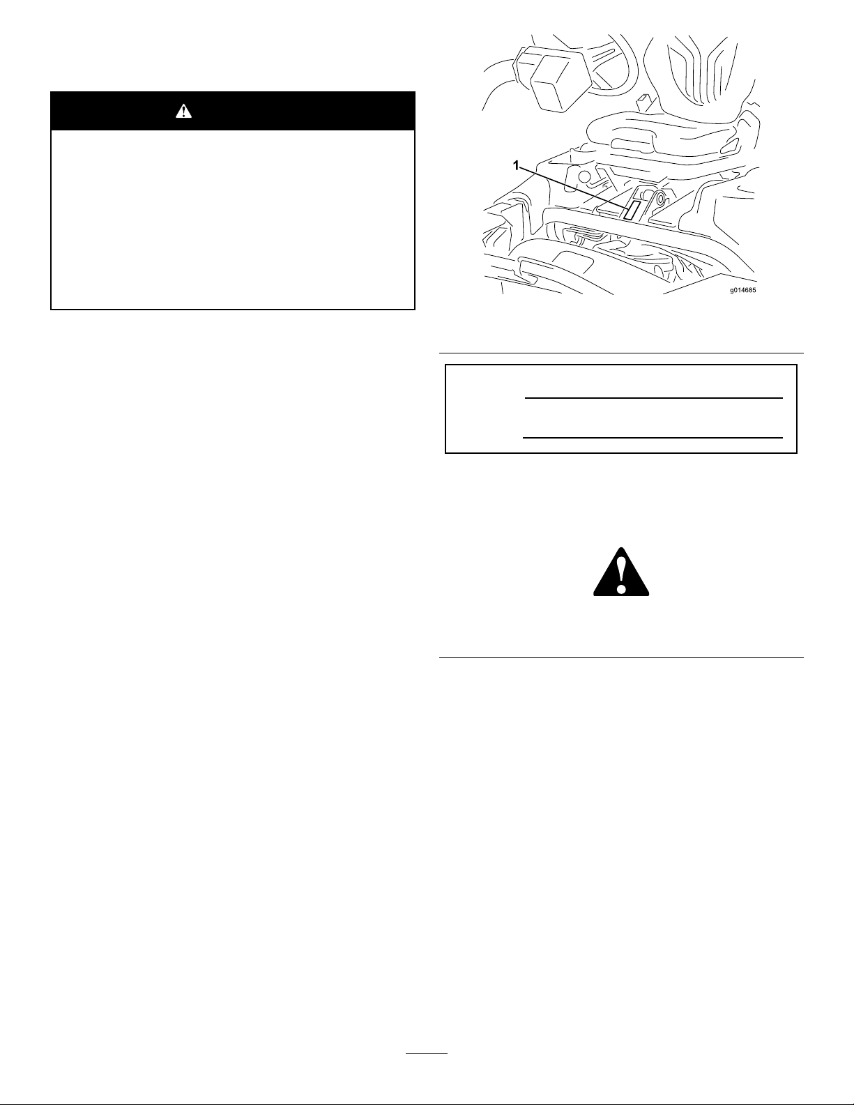
1.Modelandserialnumberlocation
ModelNo.
SerialNo.
Thismanualidentiespotentialhazardsandhassafety
messagesidentiedbythesafetyalertsymbol(Figure2),
whichsignalsahazardthatmaycauseseriousinjuryordeath
ifyoudonotfollowtherecommendedprecautions.
Figure2
1.Safetyalertsymbol
Thismanualuses2wordstohighlightinformation.
Importantcallsattentiontospecialmechanicalinformation
andNoteemphasizesgeneralinformationworthyofspecial
attention.
Wheneveryouneedservice,genuineT oroparts,oradditional
information,contactanAuthorizedServiceDealerorToro
CustomerServiceandhavethemodelandserialnumbersof
yourproductready.Figure1identiesthelocationofthe
modelandserialnumbersontheproduct.Writethenumbers
inthespaceprovided.
©2014—TheToro®Company
8111LyndaleAvenueSouth
Bloomington,MN55420
Contactusatwww.Toro.com.
2
PrintedintheUSA
AllRightsReserved
Page 3

Contents
Introduction..................................................................2
Safety...........................................................................4
SafeOperatingPractices...........................................4
ToroMowerSafety..................................................6
SoundPowerLevel..................................................8
SoundPressureLevel...............................................8
Hand-ArmVibrationLevel......................................8
WholeBodyVibrationLevel....................................8
SafetyandInstructionalDecals.................................9
Setup...........................................................................12
1InstallingtheRollBar...........................................13
2InstallingtheSeat.................................................13
3InstallingtheSteeringWheel..................................13
4ActivatingandChargingtheBattery........................14
5InstallingtheOilCooler(optional).........................15
6InstallingtheGrassBasketHooks..........................15
7InstallingtheCuttingUnits...................................16
8AddingRearWeight.............................................17
9InstallingEUDecals.............................................18
ProductOverview.........................................................18
Controls...............................................................18
Specications........................................................21
Attachments/Accessories........................................21
Operation....................................................................22
ThinkSafetyFirst...................................................22
CheckingtheEngineOil..........................................22
FillingtheFuelTank...............................................22
CheckingtheHydraulicFluidLevel...........................23
CheckingtheReel-to-BedknifeContact.....................24
CheckingtheTirePressure......................................24
CheckingtheTorqueoftheWheelNuts.....................24
BreakingintheMachine..........................................24
StartingtheEngine.................................................24
CheckingtheSafetyInterlockSystem........................25
CheckingtheLeakDetector.....................................26
InstallingandRemovingtheCuttingUnits.................27
SettingtheReelSpeed.............................................29
MowingwiththeMachine.......................................29
OperatingtheLeakDetectorAlarm..........................30
TransportingtheMachine........................................30
CleaningandInspectingtheMachine........................30
TowingtheTractionUnit.........................................30
Maintenance.................................................................32
RecommendedMaintenanceSchedule(s)......................32
DailyMaintenanceChecklist....................................33
EngineMaintenance..................................................34
ServicingtheAirCleaner.........................................34
ChangingtheEngineOilandFilter...........................34
ReplacingtheSparkPlugs........................................35
FuelSystemMaintenance...........................................35
ReplacingtheFuelFilter..........................................35
InspectingtheFuelLinesandConnections.................35
ElectricalSystemMaintenance....................................36
ServicingtheBattery...............................................36
ServicingtheFuses.................................................36
DriveSystemMaintenance.........................................37
AdjustingtheTransmissionforNeutral.....................37
AdjustingtheTransportSpeed.................................37
AdjustingtheMowingSpeed....................................38
BrakeMaintenance....................................................38
AdjustingtheBrakes...............................................38
HydraulicSystemMaintenance....................................39
ChangingtheHydraulicOilandFilter........................39
CheckingtheHydraulicLinesandHoses....................39
CuttingUnitMaintenance...........................................40
BacklappingtheReels.............................................40
DiagnosticsSystem....................................................41
DiagnosingtheServiceIndicatorLight......................41
Storage........................................................................41
3
Page 4

Safety
ThismachinemeetsorexceedsCENstandardEN
836:1997,ISOstandard5395:1990,andANSIB71.4-2012
specicationsineffectatthetimeofproductionwhen54
kg(119lb)ofweightisaddedtotherearwheel.
Note:Theadditionofattachmentsmadebyother
manufacturersthatdonotmeetAmericanNationalStandards
Institutecerticationwillcausenoncomplianceofthis
machine.
Improperuseormaintenancebytheoperatororowner
canresultininjury.Toreducethepotentialforinjury,
complywiththesesafetyinstructionsandalwayspay
attentiontothesafetyalertsymbol(Figure2),which
meansCaution,Warning,orDanger—personalsafety
instruction.Failuretocomplywiththeinstructionmay
resultinpersonalinjuryordeath.
SafeOperatingPractices
ThefollowinginstructionsareadaptedfromCENstandard
EN836:1997,ISOstandard5395:1990,andANSI
B71.4-2012.
Training
•ReadtheOperator’sManualandothertrainingmaterial
carefully.Befamiliarwiththecontrols,safetysigns,and
theproperuseoftheequipment.
•Iftheoperatorormechaniccannotreadthelanguage
ofthismanual,itistheowner’sresponsibilitytoexplain
thismaterialtothem.
•Neverallowchildrenorpeopleunfamiliarwiththese
instructionstouseorservicethemower.Local
regulationsmayrestricttheageoftheoperator.
•Nevermowwhilepeople,especiallychildren,orpetsare
nearby.
•Keepinmindthattheoperatororuserisresponsiblefor
accidentsorhazardsoccurringtootherpeopleortheir
property.
•Donotcarrypassengers.
•Alldriversandmechanicsshouldseekandobtain
professionalandpracticalinstruction.Theowneris
responsiblefortrainingtheusers.Suchinstructionshould
emphasize:
–theneedforcareandconcentrationwhenworking
withride-onmachines;
–controlofaride-onmachineslidingonaslopewill
notberegainedbytheapplicationofthebrake.The
mainreasonsforlossofcontrolare:
◊insufcientwheelgrip;
◊beingdriventoofast;
◊inadequatebraking;
◊thetypeofmachineisunsuitableforthetask;
◊lackofawarenessoftheeffectofground
conditions,especiallyslopes.
◊Theowner/usercanpreventandisresponsible
foraccidentsorinjuriesoccurringtopeople,or
damagetoproperty.
Preparation
•Whilemowing,alwayswearsubstantialfootwear,long
trousers,hardhat,safetyglasses,andhearingprotection.
Longhair,looseclothing,orjewelrymaygettangled
inmovingparts.Donotoperatetheequipmentwhen
barefootorwearingopensandals.
•Thoroughlyinspecttheareawheretheequipmentisto
beusedandremoveallobjectswhichmaybethrownby
themachine.
•Replacefaultysilencers/mufers.
•Evaluatetheterraintodeterminewhataccessoriesand
attachmentsareneededtoproperlyandsafelyperform
thejob.Onlyuseaccessoriesandattachmentsapproved
bythemanufacturer.
•Checkthatoperator’spresencecontrols,safetyswitches
andshieldsareattachedandfunctioningproperly.Donot
operateunlesstheyarefunctioningproperly.
Operation
•Donotoperatetheengineinaconnedspacewhere
dangerouscarbonmonoxidefumescancollect.
•Mowonlyindaylightoringoodarticiallight.
•Beforeattemptingtostarttheengine,disengageallblade
attachmentclutches,shiftintoneutral,andengagethe
parkingbrake.
•Rememberthereisnosuchthingasasafeslope.Travel
ongrassslopesrequiresparticularcare.T oguardagainst
overturning:
–donotstoporstartsuddenlywhengoingupor
downhill;
–machinespeedsshouldbekeptlowonslopesand
duringtightturns;
–stayalertforhumpsandhollowsandotherhidden
hazards;
–nevermowacrossthefaceoftheslope,unlessthe
mowerisdesignedforthispurpose.
•Stayalertforholesintheterrainandotherhiddenhazards.
•Watchoutfortrafcwhencrossingornearroadways.
•Stopthebladesfromrotatingbeforecrossingsurfaces
otherthangrass.
•Whenusinganyattachments,neverdirectdischargeof
materialtowardbystandersnorallowanyonenearthe
machinewhileinoperation.
•Neveroperatethemachinewithdamagedguards,shields,
orwithoutsafetyprotectivedevicesinplace.Besureall
4
Page 5

interlocksareattached,adjustedproperly ,andfunctioning
properly.
•Donotchangetheenginegovernorsettingsoroverspeed
theengine.Operatingtheengineatexcessivespeedmay
increasethehazardofpersonalinjury.
•Beforeleavingtheoperator’ sposition:
–stoponlevelground;
–disengagethepowertake-offandlowerthe
attachments;
–changeintoneutralandsettheparkingbrake;
–stoptheengineandremovethekey.
•Disengagedrivetoattachmentswhentransportingornot
inuse.
•Stoptheengineanddisengagedrivetoattachment:
–beforerefuelling;
–beforeremovingthegrasscatcher/catchers;
–beforemakingheightadjustmentunlessadjustment
canbemadefromtheoperator’sposition.
–beforeclearingblockages;
–beforechecking,cleaningorworkingonthemower;
–afterstrikingaforeignobjectorifanabnormal
vibrationoccurs.Inspectthemowerfordamage
andmakerepairsbeforerestartingandoperatingthe
equipment.
•Reducethethrottlesettingbeforestoppingtheengine
and,iftheengineisprovidedwithafuelshut-offvalve,
turnthefueloffattheconclusionofmowing.
•Keephandsandfeetawayfromthecuttingunits.
•Lookbehindanddownbeforebackinguptobesureof
aclearpath.
•Slowdownandusecautionwhenmakingturnsand
crossingroadsandsidewalks.Stopthereelswhennot
mowing.
•Donotoperatethemowerundertheinuenceofalcohol
ordrugs.
•Lightningcancausesevereinjuryordeath.Iflightning
isseenorthunderisheardinthearea,donotoperate
themachine;seekshelter.
•Usecarewhenloadingorunloadingthemachineintoa
trailerortruck.
•Usecarewhenapproachingblindcorners,shrubs,trees,
orotherobjectsthatmayobscurevision.
•Becertainthattheseatbeltcanbereleasedquicklyin
theeventofanemergency.
•Checktheareatobemowedandneverfolddowna
foldingROPSinareaswherethereareslopes,dropoffs
orwater.
•Checkcarefullyforoverheadclearances(i.e.branches,
doorways,electricalwires)beforedrivingunderany
objectsanddonotcontactthem.
•KeeptheROPSinsafeoperatingconditionby
periodicallythoroughlyinspectingfordamageand
keepingallmountingfastenerstight.
•ReplaceadamagedROPS.Donotrepairorrevise.
•DonotremovetheROPS.
•AnyalterationstoaROPSmustbeapprovedbythe
manufacturer.
SafeHandlingofFuels
•Toavoidpersonalinjuryorpropertydamage,use
extremecareinhandlinggasoline.Gasolineisextremely
ammableandthevaporsareexplosive.
•Extinguishallcigarettes,cigars,pipes,andothersources
ofignition.
•Useonlyanapprovedfuelcontainer.
•Neverremovefuelcaporaddfuelwiththeengine
running.
•Allowenginetocoolbeforerefueling.
•Neverrefuelthemachineindoors.
•Neverstorethemachineorfuelcontainerwherethereis
anopename,spark,orpilotlightsuchasonawater
heateroronotherappliances.
•Neverllcontainersinsideavehicleoronatruckor
trailerbedwithaplasticliner.Alwaysplacecontainerson
thegroundawayfromyourvehiclebeforelling.
•Removeequipmentfromthetruckortrailerandrefuelit
ontheground.Ifthisisnotpossible,thenrefuelsuch
equipmentwithaportablecontainer,ratherthanfroma
fueldispensernozzle.
•Keepthenozzleincontactwiththerimofthefueltank
orcontaineropeningatalltimesuntilfuelingiscomplete.
•Donotuseanozzlelockopendevice.
RolloverProtectionSystem(ROPS)UseandMaintenance
•TheROPSisanintegralandeffectivesafetydevice.Keep
afoldingROPSintheraisedandlockedpositionanduse
theseatbeltwhenoperatingthemachine.
•LowerafoldingROPStemporarilyonlywhenabsolutely
necessary.Donotweartheseatbeltwhenfoldeddown.
•Beawarethereisnorolloverprotectionwhenafolded
ROPSisinthedownposition.
•Iffuelisspilledonclothing,changeclothingimmediately.
•Neveroverllfueltank.Replacefuelcapandtighten
securely.
MaintenanceandStorage
•Keepallnuts,boltsandscrewstighttobesurethe
equipmentisinsafeworkingcondition.
•Neverstoretheequipmentwithfuelinthetankinsidea
buildingwherefumesmayreachanopenameorspark.
5
Page 6

•Allowtheenginetocoolbeforestoringinanyenclosure.
•Toreducetheriskofrehazard,keeptheengine,
silencer/mufer,batterycompartment,andfuelstorage
areafreeofgrass,leaves,orexcessivegrease.
•Replacewornordamagedpartsforsafety.
•Checkthegrasscatcherfrequentlyforwearor
deterioration.
•Keepallpartsingoodworkingconditionandallhardware
andhydraulicttingstightened.Replaceallwornor
damagedpartsanddecals.
•Ifthefueltankhastobedrained,dothisoutdoors.
•Becarefulduringadjustmentofthemachinetoprevent
entrapmentofthengersbetweenmovingbladesand
xedpartsofthemachine.
•Onmulti-reelmachines,takecareasrotatingonereelcan
causeotherreelstorotate.
•Disengagedrives,lowerthecuttingunits,setparking
brake,stopengineandremovekey .Waitforallmovement
tostopbeforeadjusting,cleaningorrepairing.
•Cleangrassanddebrisfromcuttingunits,drives,mufers,
andenginetohelppreventres.Cleanupoilorfuel
spillage.
•Usejackstandstosupportcomponentswhenrequired.
•Carefullyreleasepressurefromcomponentswithstored
energy.
•Disconnectbatterybeforemakinganyrepairs.Disconnect
thenegativeterminalrstandthepositivelast.Reconnect
positiverstandnegativelast.
•Usecarewhencheckingthereels.Wrapthereelsorwear
gloves,andusecautionwhenservicingthem.
•Keephandsandfeetawayfrommovingparts.Ifpossible,
donotmakeadjustmentswiththeenginerunning.
•Chargebatteriesinanopenwellventilatedarea,away
fromsparkandames.Unplugchargerbeforeconnecting
ordisconnectingfrombattery.W earprotectiveclothing
anduseinsulatedtools.
Hauling
•Usecarewhenloadingorunloadingthemachineintoa
trailerortruck.
•Usefullwidthrampsforloadingmachineintotraileror
truck.
•Tiethemachinedownsecurelyusingstraps,chains,cable,
orropes.Bothfrontandrearstrapsshouldbedirected
downandoutwardfromthemachine.
Thisproductiscapableofamputatinghandsandfeetand
throwingobjects.Alwaysfollowallsafetyinstructionsto
avoidseriousinjuryordeath.
Useofthisproductforpurposesotherthanitsintendeduse
couldprovedangeroustouserandbystanders.
Operation
•Knowhowtostoptheenginequickly.
•Alwayswearsubstantialshoes.Donotoperatethe
machinewhilewearingsandals,tennisshoes,orsneakers.
Wearingsafetyshoesandlongpantsisadvisableand
requiredbysomelocalordinancesandinsurance
regulations.
•Handlefuelcarefully.Wipeupanyspills.
•Checkthesafetyinterlockswitchesdailyforproper
operation.
•Beforeattemptingtostarttheengine,sitontheseat,pull
ontheraise/lowermowcontroltoensurethatthecutting
unitsaredisengaged,ensurethatthetractionpedalisin
neutral,andengagetheparkingbrake.
•Usingthemachinedemandsattention.Topreventloss
ofcontrol:
–Donotdriveclosetosandtraps,ditches,creeks,or
otherhazards.
–Reducespeedwhenmakingsharpturns.Avoid
suddenstopsandstarts.
–Thismachineisnotdesignedorequippedforon-road
useandisa“slow-movingvehicle.”Ifyoumustcross
ortravelonapublicroad,youshouldbeawareofand
complywithlocalregulations,suchasrequiredlights,
slowmovingvehiclesigns,andreectors.
–Watchoutfortrafcwhennearorcrossingroads.
Alwaysyieldtheright-of-way.
–Applytheservicebrakeswhengoingdownhillto
keepforwardspeedslowandtomaintaincontrolof
themachine.
•Thegrassbasketsmustbeinplaceduringoperation
ofthereelsorthatchersformaximumsafety.Shutthe
engineoffbeforeemptyingthebaskets.
•Raisethecuttingunitswhendrivingfromoneworkarea
toanother.
•Donottouchtheengine,mufer,orexhaustpipewhile
theengineisrunningorsoonafterithasstoppedbecause
theseareascouldbehotenoughtocauseburns.
•Stayclearoftherotatingscreenatthesideoftheengine
topreventdirectcontactwithyourbodyorclothing.
ToroMowerSafety
ThefollowinglistcontainssafetyinformationspecictoToro
productsorothersafetyinformationthatyoumustknowthat
isnotincludedintheANSIstandards.
•Ifacuttingunitstrikesasolidobjectorvibrates
abnormally,stopimmediately,turntheengineoff,waitfor
allmotiontostop,andinspectthemachinefordamage.
Adamagedreelorbedknifemustberepairedorreplaced
beforeoperationiscontinued.
6
Page 7

•Beforegettingoffoftheseat,movethefunctionalcontrol
levertoneutral(N),raisethecuttingunitsandwaitfor
thereelstostopspinning.Settheparkingbrake.Stopthe
engineandremovethekeyfromtheignitionswitch.
•Traverseslopescarefully.Donotstartorstopsuddenly
whentravelinguphillordownhill.
•Theoperatormustbeskilledandtrainedinhowtodrive
onhillsides.Failuretousecautiononslopesorhillsmay
causelossofcontrolandcausethemachinetotiporroll,
possiblyresultinginpersonalinjuryordeath.
•Iftheenginestallsorlosesheadwayandcannotmakeit
tothetopofaslope,donotturnthemachinearound.
Alwaysbackslowly,straightdowntheslope.
•Whenapersonorpetappearsunexpectedlyinornear
themowingarea,stopmowing.Carelessoperation,
combinedwithterrainangles,ricochets,orimproperly
positionedguardscanleadtothrownobjectinjuries.Do
notresumemowinguntiltheareaiscleared.
•Wheneverthemachineisleftunattended,makesurethe
cuttingunitsarefullyraised,thereelsarenotspinning,
thekeyisremovedfromtheignitionswitch,andthe
parkingbrakeisset.
•Ifmajorrepairsareeverneededorifassistanceisdesired,
contactanAuthorizedToroDistributor.
•Toassureoptimumperformanceandcontinuedsafety
certicationofthemachine,useonlygenuineToro
replacementpartsandaccessories.Replacementparts
andaccessoriesmadebyothermanufacturerscouldbe
dangerous,andsuchusecouldvoidtheproductwarranty.
•AlwaysusetheseatbeltwiththeROPSwhenoperating
themachine.
MaintenanceandStorage
•Makesureallhydrauliclineconnectorsaretightandall
hydraulichosesandlinesareingoodconditionbefore
applyingpressuretothesystem.
•Keepyourbodyandhandsawayfrompinholeleaksor
nozzlesthatejecthydraulicuidunderhighpressure.
Usepaperorcardboard,notyourhands,tosearchfor
leaks.Hydraulicuidescapingunderpressurecanhave
sufcientforcetopenetratetheskinandcauseserious
injury.
•Beforedisconnectingorperforminganyworkonthe
hydraulicsystem,allpressureinthesystemmustbe
relievedbystoppingtheengineandloweringthecutting
unitsandattachmentstotheground.
•Checkallfuellinesfortightnessandwearonaregular
basis.Tightenorrepairthemasneeded.
•Iftheenginemustberunningtoperformamaintenance
adjustment,keephands,feet,clothing,andanypartsof
thebodyawayfromthecuttingunits,attachments,and
anymovingparts,especiallythescreenatthesideofthe
engine.Keepeveryoneaway.
•Donotoverspeedtheenginebychanginggovernor
settings.Toensuresafetyandaccuracy,havean
AuthorizedToroDistributorcheckthemaximumengine
speedwithatachometer.
•Theenginemustbeshutoffbeforecheckingtheoilor
addingoiltothecrankcase.
7
Page 8

SoundPowerLevel
Thisunithasaguaranteedsoundpowerlevelof94dBA,
whichincludesanUncertaintyValue(K)of1dBA.
Soundpowerlevelwasdeterminedaccordingtothe
proceduresoutlinedinISO11094.
SoundPressureLevel
Thisunithasasoundpressurelevelattheoperator’searof80
dBA,whichincludesanUncertaintyValue(K)of1dBA.
Soundpressurelevelwasdeterminedaccordingtothe
proceduresoutlinedinEN836.
Hand-ArmVibrationLevel
Measuredvibrationlevelforrighthand=0.22m/s
Measuredvibrationlevelforlefthand=0.24m/s
UncertaintyValue(K)=0.12m/s
Measuredvaluesweredeterminedaccordingtotheprocedures
outlinedinEN836.
2
WholeBodyVibrationLevel
Measuredvibrationlevel=0.35m/s
UncertaintyValue(K)=0.17m/s
Measuredvaluesweredeterminedaccordingtotheprocedures
outlinedinEN836.
2
2
2
2
8
Page 9

SafetyandInstructionalDecals
Safetydecalsandinstructionsareeasilyvisibletotheoperatorandarelocatednearanyareaofpotential
danger.Replaceanydecalthatisdamagedorlost.
119-9345
115-8156
1.Reelheight3.8–Bladecuttingunit5.14–Bladecuttingunit7.Fast
2.5–Bladecuttingunit4.11–Bladecuttingunit6.Reelspeed
8.Slow
117–2718
9
Page 10

119-9346
121–5169
1.Slow
2.Continuous
variablesetting
3.Fast7.Reel—backlapping 11.Functional
4.Raisethereels8.Neutral—use
5.Reelposition
setting
6.Lowerand
engagethe
reels
forbacklapping
121–5170
1.Hydraulicoillevel4.Engine—start
2.ReadtheOperator’s
Manualbeforeservicingor
performingmaintenance.
3.Choke(gasolinemodels
only)
5.Enginepreheat/run
6.Engine—stop
9.Slow—usefor
mowing
10.Fast—usefor
transport
controllever
1.Presspedaltounlock
2.ReadtheOperator's
BatterySymbols
Someorallofthesesymbolsareonyourbattery
1.Explosionhazard
2.Nore,opename,or
smoking.
3.Causticliquid/chemical
burnhazard
4.Weareyeprotection9.Flusheyesimmediately
5.ReadtheOperator's
Manual.
6.Keepbystandersasafe
7.Weareyeprotection;
8.Batteryacidcancause
10.Containslead;donot
Manualformore
information.
distancefromthebattery.
explosivegasescan
causeblindnessandother
injuries
blindnessorsevereburns.
withwaterandgetmedical
helpfast.
discard.
121–5172
1.Off3.On
2.Headlights
10
Page 11
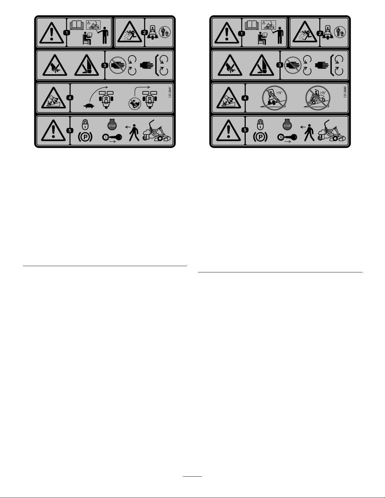
121–2641
121–2640
1.Warning—readthe
Operator’sManual,do
notoperatethismachine
unlessyouaretrained.
2.Thrownobject
hazard—keepbystanders
asafedistancefromthe
machine.
3.Cutting/dismemberment
hazardofhandorfoot,
mowerblade—stayaway
frommovingparts;keep
allguardsandshieldsin
place.
4.Tippinghazard—slow
machinebeforeturning,
donotturnathighspeeds.
5.Warning—locktheparking
brake,stoptheengine
andremovetheignition
keybeforeleavingthe
machine.
1.Warning—readthe
Operator’sManual,do
notoperatethismachine
unlessyouaretrained.
2.Thrownobject
hazard—keepbystanders
asafedistancefromthe
machine
3.Cutting/dismemberment
hazardofhandorfoot,
mowerblade—stayaway
frommovingparts;keep
allguardsandshieldsin
place.
4.Tippinghazard—donot
driveacrossslopesgreater
than15degreesordown
slopesgreaterthan15
degrees.
5.Warning—locktheparking
brake,stoptheengine
andremovetheignition
keybeforeleavingthe
machine.
11
Page 12

Setup
LooseParts
Usethechartbelowtoverifythatallpartshavebeenshipped.
ProcedureDescription
1
2
3
4
5
6
7
8
Rollbar1
Bolt(1/2x3-3/4inches)
Flange-nut(1/2inch)
Seat
Seatwiringharness
Steeringwheel
Locknut(1-1/2inches)
Washer1
Steeringwheelcap
Nopartsrequired
Nopartsrequired
Grassbaskethook
Flangebolts12
Gaugebar
Cuttingunit(model04613,04614,or
04615)
GrassBasket
Weightkit,119–7129(purchase
separately)
Qty.
4
4
1
1
1
1
1
–
–
6
1
3
3
1Addrearweight.
Use
Installtherollbar.
Installtheseattothebase.
Installthesteeringwheel.
Activateandchargethebattery.
Installtheoptionaloilcooler.
Installthegrassbaskethooks.
Installthecuttingunits.
9
Warningdecal117-95371
MediaandAdditionalParts
Description
Operator'sManual(tractionunit)
EngineOperator'sManual(engine)
PartsCatalog
OperatorTrainingMaterials
Pre-deliveryInspectionSheet
Noiseratingcerticate
Certicateofcompliance
Ignitionkeys2
Qty.
InstallEUdecals,ifrequired.
Use
1
1
1
1
1
1
1
Readbeforeoperatingthemachine.
Saveforfuturepartsordering.
Viewbeforeoperatingthemachine.
Saveforfuturereference.
Starttheengine.
12
Page 13
1
g014601
1
2
3
2
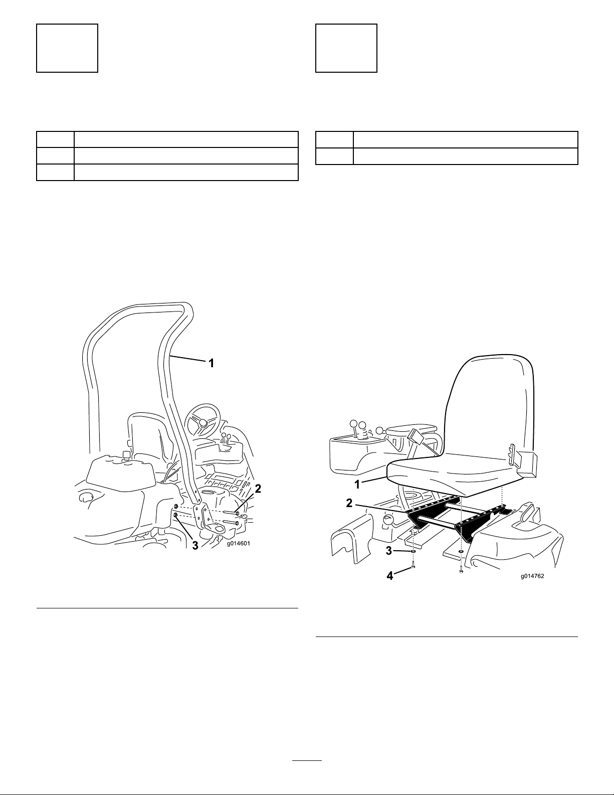
InstallingtheRollBar
Partsneededforthisprocedure:
1Rollbar
4
Bolt(1/2x3-3/4inches)
4
Flange-nut(1/2inch)
Procedure
1.Removethetopcratesupportfromthecrate.
2.Removetherollbarfromthecrate.
3.Installtherollbarintothepocketsoneachsideof
themachine,using4bolts(1/2x3-3/4inches)and4
ange-nuts(1/2inch)(Figure3).
InstallingtheSeat
Partsneededforthisprocedure:
1
Seat
1
Seatwiringharness
Procedure
Note:Mounttheseatinthefrontsetofmountingholesto
gainanadditional7.6cm(3inches)intheforwardadjustment,
orintherearmountingholesforanadditional7.6cm(3
inches)intherearwardadjustment.
1.Removeanddiscardthelagboltssecuringtheseat
slidesandcuttheshippingstraps.
2.Removethe4bolts(5/16x3/4inch)andwashers
fromtheshippingbracketanddiscardthebracket.
3.Securetheseattotheseatbasewith4boltsandwashers
removedpreviously(Figure4).
Figure3
1.Rollbar
2.Bolt(1/2x3-3/4inches)
4.Torquethefastenersto136to149N-m(100to110
ft-lb).
3.Flange-nut(1/2inch)
Figure4
1.Seat
2.Seatbase4.Bolt(5/16x3/4inch)
4.Locatetheopenconnectoronthemainwiringharness
totherightoftheseatandconnectittothewiring
harnessthatcamewiththeseat.
5.Routetheseatwiringharnessaroundtheseatslides,
ensuringthatitwillnotbepinchedwhentheseat
moves,andconnectittotheportonthebottomof
theseat.
13
3.Washer
Page 14
g014687
1
3
4
2
1.Removethefastenersandbatteryclampandliftout
thebattery.
3
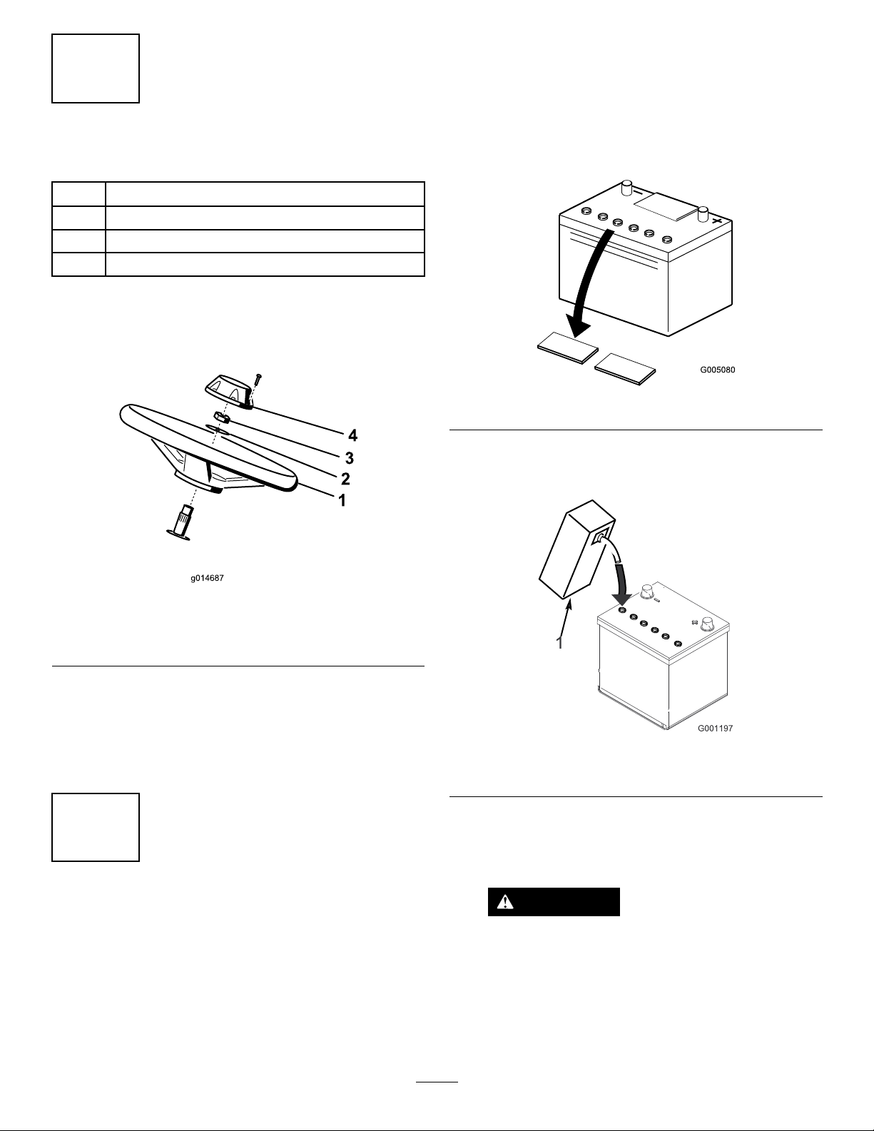
InstallingtheSteeringWheel
Partsneededforthisprocedure:
1
Steeringwheel
1
Locknut(1-1/2inches)
1Washer
1
Steeringwheelcap
Procedure
1.Slidethesteeringwheelontothesteeringshaft(Figure
5).
Important:Donotaddelectrolytewhilethe
batteryisinthemachine.Y oucouldspillit,
causingcorrosion.
2.Cleanthetopofthebatteryandremovetheventcaps
(Figure6).
Figure6
3.Carefullylleachcellwithelectrolyteuntiltheplates
arecoveredwithabout6mm(1/4inch)ofuid(Figure
7).
Figure5
1.Steeringwheel
2.Washer
2.Slidethewasherontothesteeringshaft(Figure5).
3.Securethesteeringwheeltotheshaftwithajamnut
andtightenitto27to35N-m(20to26ft-lb)(Figure5).
4.Installthecaptothesteeringwheelandsecureitwitha
screw(Figure5).
3.Jamnut
4.Cap
4
ActivatingandChargingthe Battery
NoPartsRequired
Procedure
Useonlyelectrolyte(1.265specicgravity)tollthebattery
initially.
Figure7
1.Electrolyte
4.Allowapproximately20to30minutesforthe
electrolytetosoakintotheplates.Fillasnecessaryto
bringtheelectrolytetowithinabout6mm(1/4inch)
ofthebottomofthellwell(Figure7).
WARNING
Chargingthebatteryproducesgassesthatcan
explode.
Neversmokenearthebatteryandkeepsparks
andamesawayfrombattery.
5.Connecta2to4ampbatterychargertothebattery
posts.Chargethebatteryfor2hoursat4ampsorfor
14
Page 15

4hoursat2ampsuntilthespecicgravityis1.250or
higherandthetemperatureisatleast16°C(60°F)
withallcellsgassingfreely .
6.Whenthebatteryischarged,disconnectthecharger
fromtheelectricaloutletandbatteryposts.
Note:Afterthebatteryhasbeenactivated,add
onlydistilledwatertoreplacenormalloss,although
maintenance-freebatteriesshouldnotrequirewater
undernormaloperatingconditions.
WARNING
CALIFORNIA
Proposition65Warning
Batteryposts,terminals,andrelated
accessoriescontainleadandleadcompounds,
chemicalsknowntotheStateofCalifornia
tocausecancerandreproductiveharm.
Washhandsafterhandling.
WARNING
WARNING
Incorrectbatterycableroutingcoulddamagethe
tractorandcablescausingsparks.Sparkscancause
thebatterygassestoexplode,resultinginpersonal
injury.
•Alwaysdisconnectthenegative(black)battery
cablebeforedisconnectingthepositive(red)
cable.
•Alwaysconnectthepositive(red)batterycable
beforeconnectingthenegative(black)cable.
Batteryterminalsormetaltoolscouldshort
againstmetaltractorcomponentscausing
sparks.Sparkscancausethebatterygassesto
explode,resultinginpersonalinjury.
•Whenremovingorinstallingthebattery,
donotallowthebatteryterminalstotouch
anymetalpartsofthetractor.
•Donotallowmetaltoolstoshortbetween
thebatteryterminalsandmetalpartsof
thetractor.
WARNING
Failuretocorrectlyactivatethebatterymay
resultinbatterygassingand/orpremature
batteryfailure.
7.Placethebatteryonthebatterytrayandsecureitwith
thebatteryclampandfastenersremovedpreviously.
8.Installthepositivecable(red)tothepositive(+)
terminalandthenthenegativecable(black)tothe
negative(–)terminalofthebatteryandsecurethem
withtheboltsandnuts(Figure8).Slidetherubber
bootoverthepositiveterminaltopreventapossible
shortfromoccurring.
Figure8
1.Negative(-)
2.Positive(+)
5
InstallingtheOilCooler (optional)
NoPartsRequired
Procedure
Ifyouareoperatingthemachineinhotclimates,wherethe
ambienttemperatureisabove29°C(85°F),orusingitfor
heavy-dutyuse(mowingotherthangreens,suchasfairways
orverticutting),installaHydraulicOilCoolerKit,PartNo.
119-1691,tothemachine.
15
Page 16

Important:Donotraisethesuspensiontothetransport
g014596
1
2
2
positionwhenthereelmotorsareintheholdersinthe
6
machineframe.Damagetothemotorsorhosescould
result.
InstallingtheGrassBasket
Hooks
Partsneededforthisprocedure:
6
Grassbaskethook
12Flangebolts
Procedure
Installthe6grassbaskethooksontotheendsofthe
suspensionarmbarsusing12angebolts(Figure9).
Important:Wheneverthecuttingunithastobetipped
toexposebedknife/reel,propuprearofcuttingunitto
makesurenutsonbackendofbedbaradjustingscrews
arenotrestingonworksurface(Figure10).
Figure10
1.Prop(notprovided)2.Bedknifeadjustingscrew
nut(2)
Note:Allcuttingunitsareshippedwiththecounterweight
mountedtotherightendandthemotormountanddrive
couplermountedtotheleftendofthecuttingunit.
Figure9
1.Flangebolt
2.Grassbaskethook
3.Suspensionarmbar
7
InstallingtheCuttingUnits
Partsneededforthisprocedure:
1
Gaugebar
3
Cuttingunit(model04613,04614,or04615)
3
GrassBasket
Procedure
Note:Whensharpening,settingtheheight-of-cut,or
performingothermaintenanceproceduresonthecutting
units,storethecuttingunitreelmotorsinthestoragelocation
onthefrontofthesuspensionarmstopreventdamageto
them.
1.Applygreasetotheinsidediameterofthedrivecoupler.
2.Thecuttingunitisshippedwithoutafrontroller.
Obtainaroller(ModelNo.04625,04626or04627)
fromyourlocalToroDistributor.Installtheroller
usingtheloosepartssuppliedwiththecuttingunitand
installationinstructionsincludedwiththeroller.
3.Ifinstallingthecentercuttingunit,liftuponthefoot
restandswingitup,allowingaccesstothecenter
cuttingunitposition(Figure11).
CAUTION
Thefootrestcanpinchngersifitfallsinto
theclosedposition.
Keepyourngersclearoftheareawherethe
footrestseatswhileitisopen.
16
Page 17

g014602
1
2
Figure11
g014609
1
2
3
g01461 1
1
2
g014690
1
2
3
4
1.Footrest—closed2.Footrest—open
4.Positionthecuttingunitunderthesuspensionarm.
5.Withthelatchesonthesuspension-armbarpointing
up(i.e.,open)(Figure12),pushthesuspensionarm
downsothatthebartsoverthebaracrossthetopof
thecuttingunit(Figure13).
Note:A“click”canbeheardandfeltwhenthelatches
areproperlylockedinplace.
7.Coatthesplineshaftofthecuttingunitmotorwith
cleangrease(Figure14).
8.Insertthemotorintotheleftsideofthecuttingunit
(asviewedfromtheoperator'sposition)andpullthe
motorretainingbaronthecuttingunittowardthe
motoruntilyouhearanaudible“click”frombothsides
ofthemotor(Figure14).
Figure12
1.Latch—closedposition3.Latch—openposition
2.Suspension-armbar
Figure13
Figure14
1.Reelmotor
2.Splineshaft
9.Mountagrassbasketontothebaskethooksonthe
suspensionarm.
10.Repeatthisprocedurefortheothercuttingunits.
3.Cavity
4.Motorretainingbar
1.Suspension-armbar2.Cutting-unitbar
6.Closethelatchesdownandaroundthecutting-unitbar
andlocktheminplace(Figure12).
17
Page 18

8
g014674
1
2
3
4
5
6
7
8
AddingRearWeight
Partsneededforthisprocedure:
1
Weightkit,119–7129(purchaseseparately)
Procedure
ThisunitcomplieswiththeANSIB71.4-2004andEN836
Standardswhenequippedwithweightkit119-7129.
9
InstallingEUDecals
Partsneededforthisprocedure:
1Warningdecal117-9537
Procedure
ProductOverview
Figure15
1.Engine
2.Rollbar6.Tractionpedal
3.Controlpanel
4.Seat8.Cuttingunits
5.Steeringwheel
7.Footrest
IfthismachinewillbeusedintheEU,afxthewarningdecal
117-9537overEnglishwarningdecal117-9536.
Controls
TractionPedal
Thetractionpedal(Figure16)has3functions:tomakethe
machinemoveforward,tomoveitbackward,andtostopthe
machine.Pressthetopofthepedaltomoveforwardandthe
bottomofthepedaltomovebackwardortoassistinstopping
whenmovingforward.Also,allowthepedaltomovetothe
neutralpositiontostopthemachine.Foroperatorcomfort,
donotresttheheelofyourfootonreversewhenoperating
forward(Figure17).
18
Page 19

g014603
1
2
3
Figure16
g014771
1
3
2
4
5
6
7
8
1.Tractionpedal—forward3.Steeringarmlockingpedal
2.Tractionpedal—reverse
Figure17
Figure18
1.Ignitionswitch5.Throttlecontrol
2.Choke6.Serviceindicatorlight
3.Functional-controllever7.Engineoilpressurelight
4.Raise/LowerMowControl
8.Leakindicatorlight
Choke
Tostartacoldengine,closethecarburetorchokebypulling
thechokecontrol(Figure18)outtotheClosedposition.
Aftertheenginestarts,regulatethechoketokeeptheengine
runningsmoothly.Assoonaspossible,openthechokeby
pushingitintotheOpenposition.Awarmenginerequires
littleornochoking.
Raise/LowerMowControl
SteeringArmLockingPedal
Pressthepedal(Figure16)andraiseorlowerthesteering
armforoperatorcomfort,then,releasethepedaltolockthe
arminplace.
Movingthecontrol(Figure18)forwardduringoperation
lowersthecuttingunitsandstartsthereels.Pullbackonthe
controltostopthereelsandraisethecuttingunits.During
operationthereelscanbestoppedbypullingbackonthe
controlmomentarilyandreleasingit.Startthereelsby
movingthecontrolforward.
ThrottleControl
FunctionalControlLever
Thethrottlecontrol(Figure18)givestheoperatortheability
tocontrolthespeedoftheengine.Movingthethrottle
controltowardtheFastpositionincreasestheenginespeed;
movingthethrottlecontroltowardSlowwilldecreasethe
enginespeed.Groundspeedsareasfollows:
•3.2to8km/h(2to5mph)forwardmowingspeed
•16km/h(10mph)maximumtransportspeed
•4.0km/h(2.5mph)reversespeed
Note:Theenginecannotbestoppedbytheuseofthe
throttlecontrol.
Thefunctionalcontrollever(Figure18)provides2traction
selectionsplusaNeutralposition.Itispermissibletoshift
frommowtotransportortransporttomow(nottoneutral)
whilethemachineisinmotion.Nodamagewillresult.
•RearPosition—neutralandbacklapping
•MiddlePosition—usedformowingoperation
•FrontPosition—usedfortransportoperation
19
Page 20

IgnitionSwitch
g014600
1
g01461 0
g014620
1
2
ParkingBrakeLever
Insertthekeyintotheswitch(Figure18)andturnitclockwise
asfaraspossibletotheStartpositiontostarttheengine.
Releasethekeyassoonastheenginestarts;thekeywillmove
totheOnposition.TurnthekeycounterclockwisetotheOff
positiontostoptheengine.
EngineOilPressureLight
Thelight(Figure18)glowsiftheengineoilpressuredrops
belowasafelevel.
ServiceIndicatorLight
Theserviceindicatorlight(Figure18)illuminateswhenthe
machinesensorsdetectanissuewith1ofthesystemsof
themachine.Ifthislightilluminates,stopwhatyouare
doinganddrivetoasafelocationwhereyouoraservice
techniciancandiagnosetheproblem.Formoreinformation
ondiagnosingsystemissuesusingtheserviceindicatorlight,
refertoDiagnosingtheServiceIndicatorLight(page41).
LeakIndicatorLight
Thislightilluminatesandanalarmsoundsifthehydraulic
uidleveldropsinthehydraulicreservoir.RefertoChecking
theLeakDetector(page26).
HourMeter
Thehourmeter(Figure19)indicatesthetotalhoursthe
machinehasoperated.Itstartstofunctionwheneverthekey
switchisrotatedtoOn.
Pulluponthebrakelever(Figure20)tosettheparking
brake.Disengageitbypushingitforwardanddown.Lock
theparkingbrakeanytimeyouleavethemachine.
Figure20
BacklapLever
Thebacklapleverislocatedundertheplasticcovertotheleft
oftheseat.Usethebacklaplever(Figure21)inconjunction
withtheraise/lowermowcontrolleverandthereel-speed
controlforbacklappingthereels.
1.Hourmeter
Figure19
Figure21
1.Backlaplever—mow
position
2.Backlaplever—backlap
position
ReelSpeedControl
Thereelspeedcontrolislocatedundertheplasticcoverto
theleftoftheseat.Usethereelspeedcontrol(Figure22)to
adjustthespeedofthereels.
20
Page 21

g014623
1
1.Reelspeedcontrol
g014628
1
g01462 6
1
Seat-AdjustingLever
FuelShutoffValve
Closethefuelshutoffvalve(Figure24),behindtheseatand
underthefueltank,whenstoringortransportingthemachine
onatruckortrailer.
Figure22
Theseatadjustingleverislocatedonthefront,rightcorner
oftheseat(Figure23),allowingyoutoadjusttheseatfore
andaft.
Note:Ifyouneedadditionaladjustmentontheseat,youcan
removethe4boltssecuringtheseattothebaseandmovethe
seattothesecondsetofmountingholesprovided.
Figure24
1.Fuelshutoff(underthefueltank)
Specications
Note:Specicationsanddesignaresubjecttochange
withoutnotice.
Widthofcut151cm(59.5inches)
Wheeltread
Wheelbase
Overalllength(w/baskets)249cm(98.0inches)
Overallwidth179cm(70.6inches)
Overallheight205cm(80.8inches)
NetWeightw/reels(8Blade)633kg(1,395lb)
128cm(50.5inches)
119cm(46.9inches)
1.Seat-adjustinghandle
Figure23
Attachments/Accessories
AselectionofToroapprovedattachmentsandaccessoriesis
availableforusewiththemachinetoenhanceandexpand
itscapabilities.ContactyourAuthorizedServiceDealeror
Distributororgotowww .Toro.comforalistofallapproved
attachmentsandaccessories.
21
Page 22

Operation
FillingtheFuelTank
Note:Determinetheleftandrightsidesofthemachine
fromthenormaloperatingposition.
ThinkSafetyFirst
Pleasecarefullyreadallofthesafetyinstructionsandsymbols
inthesafetysection.Knowingthisinformationcouldhelp
youorbystandersavoidinjury.
Theuseofprotectiveequipment,suchasbutnotlimitedto,
foreyes,ears,feet,andheadisrecommended.
CheckingtheEngineOil
Theengineisshippedwith1.65liters(1-3/4quarts)(w/lter)
ofoilinthecrankcase;however,theoillevelmustbechecked
beforeandaftertheengineisrststarted.
Theengineusesanyhigh-qualitydetergentoilhavingthe
AmericanPetroleumInstitute(API)serviceclassicationof
SG,SH,orSJorhigher.Therecommendedviscosity(weight)
isSAE30.
1.Positionthemachineonalevelsurface.
2.Unscrewthedipstickandwipeitwithacleanrag.
3.Screwthedipstickintothetubeandmakesureitis
seatedfully(Figure25).
RecommendedFuel
•Forbestresults,useonlyclean,fresh(lessthan30days
old),unleadedgasolinewithanoctaneratingof87or
higher((R+M)/2ratingmethod).
•Ethanol:Gasolinewithupto10%ethanol(gasohol)
or15%MTBE(methyltertiarybutylether)byvolume
isacceptable.EthanolandMTBEarenotthesame.
Gasolinewith15%ethanol(E15)byvolumeisnot
approvedforuse.Neverusegasolinethatcontainsmore
than10%ethanolbyvolume,suchasE15(contains15%
ethanol),E20(contains20%ethanol),orE85(contains
85%ethanol).Usingunapprovedgasolinemaycause
performanceproblemsand/orenginedamagewhichmay
notbecoveredunderwarranty.
•Donotusegasolinecontainingmethanol.
•Donotstorefueleitherinthefueltankorfuelcontainers
overthewinterunlessafuelstabilizerisused.
•Donotaddoiltogasoline.
DANGER
Incertainconditions,gasolineisextremely
ammableandhighlyexplosive.Areorexplosion
fromgasolinecanburnyouandothersandcan
damageproperty.
Figure25
1.Dipstick2.Fillercap
4.Unscrewthedipstickoutofthetubeandcheckthe
oillevel.
5.Iftheoillevelislow,removethellercapfromthe
valvecoverandpouroilintotheopeninginthevalve
coveruntiltheoillevelisuptotheFullmarkonthe
dipstick.Addtheoilslowlyandchecktheleveloften
duringthisprocess.Donotoverll.
•Fillthefueltankoutdoors,inanopenarea,
whentheengineiscold.Wipeupanygasoline
thatspills.
•Neverllthefueltankinsideanenclosedtrailer.
•Donotllthefueltankcompletelyfull.Add
gasolinetothefueltankuntilthelevelis25
mm(1inch)belowthebottomofthellerneck.
Thisemptyspaceinthetankallowsgasolineto
expand.
•Neversmokewhenhandlinggasoline,andstay
awayfromanopenameorwheregasoline
fumesmaybeignitedbyaspark.
•Storegasolineinanapprovedcontainerand
keepitoutofthereachofchildren.Neverbuy
morethana30-daysupplyofgasoline.
•Donotoperatewithoutentireexhaustsystemin
placeandinproperworkingcondition.
Important:Checktheoillevelevery8operating
hoursordaily .
6.Installthellercapanddipstickrmlyinplace.
22
Page 23

DANGER
Incertainconditionsduringfueling,static
electricitycanbereleasedcausingasparkwhich
canignitethegasolinevapors.Areorexplosion
fromgasolinecanburnyouandothersandcan
damageproperty.
•Alwaysplacegasolinecontainersontheground
awayfromyourvehiclebeforelling.
•Donotllgasolinecontainersinsideavehicleor
onatruckortrailerbedbecauseinteriorcarpets
orplastictruckbedlinersmayinsulatethe
containerandslowthelossofanystaticcharge.
•Whenpractical,removegas-poweredequipment
fromthetruckortrailerandrefueltheequipment
withitswheelsontheground.
•Ifthisisnotpossible,thenrefuelsuch
equipmentonatruckortrailerfromaportable
container,ratherthanfromagasolinedispenser
nozzle.
•Ifagasolinedispensernozzlemustbeused,
keepthenozzleincontactwiththerimofthe
fueltankorcontaineropeningatalltimesuntil
fuelingiscomplete.
1.Cleanaroundthefueltankcapandremoveit(Figure
26).
uid.Beforeoperatingthemachineeachday,checklevelof
thehydraulicuidinthewhiteplasticwindowonthefrontof
thehydraulicuidreservoir(behindtheseatontheleftside).
Theuidshouldbebetweenthelinesinthewindow;ifnot,
addanappropriateuidasdescribedinthefollowingsections:
Therecommendedreplacementuidisasfollows:
ToroPremiumAllSeasonHydraulicFluid(Availablein5
gallonpailsor55gallondrums.SeepartscatalogorToro
distributorforpartnumbers.)
Alternateuids:IftheTorouidisnotavailable,otheruids
maybeusedprovidedtheymeetallthefollowingmaterial
propertiesandindustryspecications.W edonotrecommend
theuseofsyntheticuid.Consultwithyourlubricant
distributortoidentifyasatisfactoryproduct
Note:Torowillnotassumeresponsibilityfordamage
causedbyimpropersubstitutions,souseonlyproducts
fromreputablemanufacturerswhowillstandbehindtheir
recommendation.
HighViscosityIndex/LowPourPointAnti-wearHydraulic
Fluid,ISOVG46
MaterialProperties:
Viscosity,ASTMD445cSt@40°C44to48
ViscosityIndexASTMD2270
PourPoint,ASTMD97-34°Fto-49°F
IndustrySpecications:
VickersI-286-S(QualityLevel),VickersM-2950-S
(QualityLevel),DenisonHF-0
cSt@100°C7.9to8.5
140to160
Figure26
1.Fueltankcap
2.Addunleadedregulargasolinetothefueltankuntilthe
levelis25mm(1inch)belowthebottomoftheller
neck.
Thisspaceinthetankallowsgasolinetoexpand.Do
notllthefueltankcompletelyfull.
Note:Fueltankcapacityis26.6liters(7U .S.gallons)
3.Installthefueltankcapsecurely.Wipeupanygasoline
thatmayhavespilled.
CheckingtheHydraulicFluid Level
Thehydraulicuidreservoirislledatthefactorywith
approximately25.7L(6.8USgallons)ofhighqualityhydraulic
Important:TheISOVG46Multigradeuidhasbeen
foundtoofferoptimalperformanceinawiderangeof
temperatureconditions.Foroperationinconsistently
highambienttemperatures,18°C(65°F)to49°C
(120°F),ISOVG68hydraulicuidmayofferimproved
performance.
PremiumBiodegradableHydraulicFluid-MobilEAL
EnviroSyn46H
Important:MobilEALEnviroSyn46Histheonly
syntheticbiodegradableuidapprovedbyT oro.This
uidiscompatiblewiththeelastomersusedinToro
hydraulicsystemsandissuitableforawide-range
oftemperatureconditions.Thisuidiscompatible
withconventionalmineraloils,butformaximum
biodegradabilityandperformancethehydraulicsystem
shouldbethoroughlyushedofconventionaluid.The
oilisavailablein19L(5gallon)containersor55gallon
drumsfromyourMobilDistributor.
Important:Manyhydraulicuidsarealmostcolorless,
makingitdifculttospotleaks.Areddyeadditive
forthehydraulicsystemoilisavailablein20ml(2/3
oz)bottles.Onebottleissufcientfor15-22L(4-6
gallons)ofhydraulicoil.Orderpartno.44-2500from
yourauthorizedTorodistributor.
T his r ed dy e is not
23
Page 24

r ecommended f or use with biodeg rada ble uids. Use
f ood coloring .
Important:Regardlessofthehydraulicuidtype
used,anytractionunitusedforoffgreenapplications,
verticuttingorusedduringambienttemperaturesabove
29°C(85°F)shouldhaveOilCoolerKitinstalled;refer
to5InstallingtheOilCooler(optional)(page15).
FillingtheHydraulicTank
previouslybeenacceptable.Theremustbelightcontact
acrossthefulllengthofthereelandbedknife;referto
AdjustingtheReeltoBedknifeintheCuttingUnitOperator’s
Manual.
CheckingtheTirePressure
Thetiresareover-inatedatthefactoryforshipping
purposes.Reducethepressuretotheproperlevelsbefore
startingtheunit.
1.Positionthemachineonalevelsurface.Makesurethe
machinehascooleddownsotheoiliscold.
2.Removethecapfromthereservoir(Figure27).
Figure27
Varythetirepressureforthefrontwheels,dependingupon
yourturfconditions,fromaminimumof83toamaximum
of110kPa(12psito16psi).
Varythetirepressurefortherearwheelfromaminimumof
83toamaximumof110kPa(12psito16psi).
CheckingtheTorqueofthe WheelNuts
WARNING
Failuretomaintainpropertorqueofthewheelnuts
couldresultinpersonalinjury.
Torquethewheelnutsto94.4-122N-m(70-90ft-lb)
after1-4hoursofoperationandagainafter10hours
ofoperation.Torqueevery200hoursthereafter.
BreakingintheMachine
Refertotheenginemanualsuppliedwiththemachineforoil
changeandmaintenanceproceduresrecommendedduring
thebreak-inperiod.
1.Hydraulictankcap
2.Breather
3.Slowlyllthereservoirwiththeappropriatehydraulic
uiduntilthelevelreachestheFullmarkinthewhite
windowinthefrontofthereservoir.Donotoverll.
Important:Topreventsystemcontamination,
cleanthetopofthehydraulicuidcontainers
beforepuncturing.Ensurethepourspoutand
funnelareclean.
4.Installthereservoircap.Wipeupanyuidthatmay
havespilled.
Important:Checklevelofhydraulicuidbefore
engineisrststartedanddailythereafter.
CheckingtheReel-to-Bedknife Contact
Eachdaybeforeoperatingthemachine,checkthe
reel-to-bedknifecontact,regardlessifthequalityofcuthad
Only8hoursofmowingoperationisrequiredforthebreak-in
period.
Sincethersthoursofoperationarecriticaltofuture
dependabilityofthemachine,monitoritsfunctionsand
performancecloselysothatminordifculties,whichcould
leadtomajorproblems,arenotedandcanbecorrected.
Inspectthemachinefrequentlyduringbreak-inforsignsof
oilleakage,loosefasteners,oranyothermalfunction.
Toensureoptimumperformanceofthebrakesystem,burnish
(break-in)thebrakesbeforeusingthemachine.Toburnish
thebrakes,rmlyapplythebrakesanddrivethemachineat
mowingspeeduntilthebrakesarehot,asindicatedbytheir
smell.Anadjustmenttothebrakesmayberequiredafter
break-in;refertoAdjustingtheBrakes(page38).
StartingtheEngine
Note:Inspecttheareabeneaththemowerstobecertain
theyareclearofdebris.
1.Sitontheseat,locktheparkingbrake,disengagethe
raise/lowermowcontrolandmovethefunctional
controllevertoNeutral.
24
Page 25

2.Removeyourfootfromthetractionpedalandmake
surethepedalisintheNeutralposition.
3.Movethechokelevertotheclosedposition(onlywhen
startingacoldengine)andthethrottlelevertothehalf
throttleposition.
4.Insertandrotatetheignitionkeyclockwiseuntilthe
enginestarts.Aftertheenginestarts,regulatethe
choketokeeptheenginerunningsmoothly.Assoon
aspossible,openthechokebypullingitrearwardto
theOffposition.Awarmenginerequireslittleorno
choking.
5.Checkthemachineoutwiththefollowingprocedures
aftertheenginehasstarted:
A.MovethethrottlecontroltotheFastposition
andmomentarilyengagethereelsbymoving
theraise/lowermowcontrolleverforward.The
cuttingunitsshoulddropandallthereelsshould
turn.
B.Movetheraise/lowermowcontrolleverrearward.
Thecuttingreelsshouldstopandthecuttingunits
shouldraisetothefulltransportposition.
C.Setthebraketokeepthemachinefrommoving,
andoperatethetractionpedalthroughthe
forwardandreversepositions.
D.Continuetheaboveprocedurefor1-2minutes.
Neutralizethefunctionalcontrollever,lockthe
parkingbrake,andturntheengineoff.
E.Checkforoilleaks.Ifoilleaksappear,check
thetightnessofthehydraulicttings.Ifoil
leakscontinuetoappear,contactyourlocal
ToroDistributorforassistanceand,ifnecessary,
replacementparts.
Important:Atraceofoilonthemotoror
wheelsealsisnormal.Sealsrequireasmall
amountoflubricationtoperformproperly.
Note:Whenthemachineisnewandthebearings
andreelsaretight,itisnecessarytousetheFast
throttlecontrolpositionforthischeck.Afast
throttlesettingmaynotberequiredafterthe
break-inperiod.
CheckingtheSafetyInterlock System
CAUTION
Ifthesafetyinterlockswitchesaredisconnectedor
damagedthemachinecouldoperateunexpectedly
causingpersonalinjury.
•Donottamperwiththeinterlockswitches.
•Checktheoperationoftheinterlockswitches
dailyandreplaceanydamagedswitchesbefore
operatingthemachine.
Thepurposeofthesafetyinterlocksystemistoprevent
operationofthemachinewherethereispossibleinjuryto
theoperatororthemachine.
Thesafetyinterlocksystempreventstheenginefromstarting
unless:
•Thetractionpedalisinneutral.
•Thefunctionalcontrolleverisinneutral.
Thesafetyinterlocksystempreventsthemachinefrom
movingunless:
•Theparkingbrakeisoff.
•Theoperatorisseated.
•ThefunctionalcontrolleverisinMoworTransport.
Thesafetyinterlocksystempreventsthereelsfromoperating
unlessthefunctionalcontrolleverisintheMowposition.
Performthefollowingsystemchecksdailytobesurethe
interlocksystemisoperatingcorrectly:
1.Sitontheseat,movethetractionpedaltoNeutral,
movethefunctionalcontrollevertoNeutral,and
engagetheparkingbrake.Trytodepressthetraction
pedal.Thepedalshouldnotdepress,whichmeansthat
theinterlocksystemisoperatingcorrectly.Correctthe
problemifitisnotoperatingproperly.
2.Sitontheseat,movethetractionpedaltoNeutral,
movethefunctionalcontrollevertoNeutral,and
engagetheparkingbrake.Movethefunctionalcontrol
levertomowortransportandtrytostarttheengine.
Theengineshouldnotcrank,whichmeansthatthe
interlocksystemisoperatingcorrectly.Correctthe
problemifitisnotoperatingproperly.
3.Sitontheseat,movethetractionpedaltoNeutral,
movethefunctionalcontrollevertoNeutral,and
engagetheparkingbrake.Starttheengineandmove
thefunctionalcontrollevertomowortransport.The
engineshouldkill,whichmeansthattheinterlock
systemisoperatingcorrectly.Correcttheproblemifit
isnotoperatingproperly.
4.Sitontheseat,movethetractionpedaltoNeutral,
movethefunctionalcontrollevertoNeutral,and
engagetheparkingbrake.Starttheengine.Release
theparkingbrake,movethefunctionalcontrollever
tomow ,andrisefromtheseat.Theengineshould
kill,whichmeansthattheinterlocksystemisoperating
correctly.Correcttheproblemifitisnotoperating
properly.
5.Sitontheseat,movethetractionpedaltoNeutral,
movethefunctionalcontrollevertoNeutral,and
engagetheparkingbrake.Starttheengine.Movethe
raise/lowermowcontrolforwardtolowerthecutting
units.Thecuttingunitsshouldnotstartrotating.If
theydo,theinterlocksystemisnotoperatingcorrectly.
Correcttheproblem.
25
Page 26

CheckingtheLeakDetector
G020735
G020736
G020737
Theleakdetectorsystemisdesignedtoassistinearly
detectionofhydraulicoilsystemleaks.Iftheoillevelinthe
mainhydraulicreservoir,isloweredby118-177ml(4to6
ounces),theoatswitchinthetankwillclose.Afteraone
seconddelay ,thealarmwillsound,alertingtheoperator
(Figure30).Expansionofoil,duetonormalheatingduring
machineoperation,willcausetheoiltotransferintothe
auxiliaryoilreservoir.Theoilisallowedtoreturntothemain
tankwhentheignitionswitchisturnedoff.
Figure29
Normaloperation(oilwarm)
Figure28
Beforestart(oilcold)
1.Breathercap
2.Fillerneck6.Floatraisedswitchopen
3.Overowtube
4.Sightwindow8.Fluidlevel(cold)
5.Solenoidreturnvalveopen
7.Nosound
1.Solenoidreturnvalve
closed
2.Floatraisedswitchopen
1.Floatdownswitchclosed
Fluidleveldown1 18–177
ml(4to6ounces)
2.Warningbuzzer
3.Warningbuzzer
4.Fluidlevel(warm)
Figure30
LeakAlert!
3.Fluidlevel(warm)
CheckingtheLeakDetectorSystem
Operation
1.MovetheignitionswitchtotheOnposition.Donot
starttheengine.
2.Removethehydraulictankcapandstrainerfromthe
neckofthetank.
3.Insertacleanrodorscrewdriverintothetankneckand
gentlypushdownontheswitchoat(Figure31).The
alarmshouldsoundaftertheone-seconddelay.
26
Page 27

Figure31
g014602
1
2
g014609
1
2
3
g01461 1
1
2
downsothatthebartsoverthebaracrossthetopof
thecuttingunit(Figure34).
Figure33
1.Latch—closedposition3.Latch—openposition
2.Suspension-armbar
1.Cleanrodorscrewdriver
2.Pressdownonswitch
3.Warningbuzzer
4.Releasetheoat.Thealarmshouldstopsounding.
5.Installthestrainerscreenandhydraulictankcap.Move
theignitionswitchtotheOffposition.
InstallingandRemovingthe CuttingUnits
InstallingtheCuttingUnits
1.Liftuponthefootrestandswingitopen,allowing
accesstothecentercuttingunitposition(Figure32).
CAUTION
Thefootrestcanpinchngersifitfallsinto
theclosedposition.
Keepyourngersclearoftheareawherethe
footrestseatswhileitisopen.
Figure34
1.Suspension-armbar2.Cutting-unitbar
4.Closethelatchesdownandaroundthecutting-unitbar
andlocktheminplace(Figure33).
Note:A“click”canbeheardandfeltwhenthelatches
areproperlylockedinplace.
5.Coatthesplineshaftofthecuttingunitmotorwith
cleangrease(Figure35).
6.Insertthemotorintotheleftsideofthecuttingunit
(asviewedfromtheoperator'sposition)andpullthe
motorretainingbaronthecuttingunittowardthe
Figure32
1.Footrest—closed2.Footrest—open
2.Positionthecuttingunitunderthecentersuspension
motoruntilyouhearanaudible“click”frombothsides
ofthemotor(Figure35).
arm.
3.Withthelatchesonthesuspension-armbarpointing
up(i.e.,open)(Figure33),pushthesuspensionarm
27
Page 28

g014690
1
2
3
4
g014605
1
2
Figure36
g014608
1.Reelmotor2.Motorretainingbar
3.Movethemotortothestoragelocationonthefrontof
thesuspensionarm(Figure37).
Figure35
1.Reelmotor
2.Splineshaft
3.Cavity
4.Motorretainingbar
7.Mountagrassbasketontothebaskethooksonthe
suspensionarm.
8.Repeatthisprocedurefortheothercuttingunits.
RemovingtheCuttingUnits
1.Parkthemachineonacleanlevelsurface,lower
thecuttingunitstothegrounduntilthesuspension
hydraulicsarefullyextended,stoptheengine,andset
theparkingbrake.
2.Pushthemotorretainingbaroutoftheslotsonthe
motortowardsthecuttingunitandremovethemotor
fromthecuttingunit.
Figure37
Note:Whensharpening,settingtheheight-of-cut,
orperformingothermaintenanceproceduresonthe
cuttingunits,storethecuttingunitreelmotorsinthe
storagelocationonthefrontofthesuspensionarmsto
preventdamagetothem.
Important:Donotraisethesuspensiontothe
transportpositionwhenthereelmotorsareinthe
holdersinthemachineframe.Damagetothe
motorsorhosescouldresult.Ifyoumustmovethe
tractionunitwithoutthecuttingunitsinstalled,
securethemtothesuspensionarmsusingcable
ties.
4.Openthelatchesonthesuspension-armbarofthe
cuttingunityouareremoving(Figure33).
5.Disconnectthelatchesfromthecutting-unitbar.
6.Rollthecuttingunitoutfromunderthesuspension
arm.
7.Repeatsteps2through6fortheothercuttingunits
asrequired.
28
Page 29

SettingtheReelSpeed
g014736
g014623
1
Toachieveaconsistent,highquality–of–cutandauniform
aftercutappearance,itisimportantthatthereelspeedcontrol
(locatedonthemanifoldblockunderthecovertotheleft
oftheseat)becorrectlyset.
Adjustthereelspeedcontrolasfollows:
1.Selecttheheight-of-cutatwhichthecuttingunitsare
set.
2.Choosethedesiredgroundspeedbestsuitedfor
conditions.
3.Usingtheappropriategraph(SeeFigure38)for5,8,
11,or14bladecuttingunits,determinetheproperreel
speedsetting.
Note:Youcanincreaseordecreasethereelspeedto
compensateforturfconditions.
MowingwiththeMachine
Note:Beforemowinggreenswiththemachine,itis
recommendedthatyoundaclearareaandpracticestarting
andstopping,raisingandloweringthecuttingunits,turning,
etc.Thistrainingperiodwillbebenecialtotheoperatorin
gainingcondenceintheperformanceofthemachine.
Note:Beforemowing,inspectthegreenfordebris,remove
theagfromthecup,anddeterminethebestdirectionto
mow .Basethedirectiontomowonthepreviousmowing
direction.Alwaysmowinanalternatepatternfromthe
previousmowingsothatthegrassbladeswillbelessaptto
laydownandthereforebedifculttotrapbetweenthereel
bladesandbedknife.
1.Approachthegreenwiththefunctionalcontrolleverin
theMowpositionandthethrottleatfullspeed.Start
ononeedgeofthegreensotheribbonprocedure
ofcuttingmaybeused.Thisholdscompactiontoa
minimumandleavesaneat,attractivepatternonthe
greens.
Figure38
4.Tosetthereelspeed,rotatetheknob(Figure39)
untiltheindicatorarrowsareinlinewiththenumber
designatingdesiredsetting.
2.Actuatetheraise/lowermowleverasthefrontedge
ofthegrassbasketscrosstheouteredgeofthegreen.
Thisproceduredropsthecuttingunitstotheturfand
startsthereels.
Important:Familiarizeyourselfwiththefactthat
theNo.1cuttingunitreelisdelayedandtherefore,
youshouldpracticetotrytogaintherequired
timingnecessarytominimizethecleanupmowing
operation.
3.Overlapaminimalamountwiththepreviouscut
onreturnpasses.Toassistinmaintainingastraight
lineacrossthegreenandkeepthemachineanequal
distancefromtheedgeofthepreviouscut,establish
animaginarysightlineapproximately1.8to3m(6to
10ft)aheadofthemachinetotheedgeoftheuncut
portionofthegreen(Figure40).Somenditusefulto
includetheouteredgeofthesteeringwheelaspartof
thesightline;i.e.keepthesteeringwheeledgealigned
withapointthatisalwayskeptthesamedistanceaway
fromthefrontofthemachine(Figure40).
4.Asthefrontofthebasketscrosstheedgeofthegreen,
movetheraise/lowermowleverrearward.Thiswill
stopthereelsandliftthecuttingunits.Timingofthis
procedureisimportant,sothemowersdonotcutinto
thefringearea.However,asmuchofthegreenas
possibleshouldbecuttominimizetheamountofgrass
lefttomowaroundtheouterperiphery.
1.Reelspeedcontrol
Figure39
5.Cutdownonoperatingtimeandeaselineupforthe
nextpassbymomentarilyturningthemachineinthe
oppositedirection,thenturninginthedirectionof
theuncutportion;i.e.,ifintendingtoturnright,rst
29
Page 30

swingslightlyleft,thenright.Thiswillassistingetting
G017821
1
3
2
themachinemorequicklyalignedforthenextpass.
Followthesameprocedureforturningintheopposite
direction.Itisagoodpracticetotrytomakeasshort
ofaturnaspossible.However,turninawiderarc
duringwarmerweathertominimizethepossibilityof
bruisingtheturf.
Figure40
OperatingtheLeakDetector Alarm
Theleakdetectoralarmmaysoundforoneofthefollowing
reasons:
•Aleakof118-177ml(4to6ounces)hasoccurred.
•Theoillevelinthemainreservoirisreducedby118-177
ml(4to6ounces)duetocontractionoftheoilbycooling.
Ifthealarmsounds,itshouldbeturnedoffasquicklyas
possibleandinspectedforleaks.Ifthealarmsoundswhile
operatingonagreenitmaybeappropriatetodriveoffthe
greenrst.Thesourceoftheleakshouldbedeterminedand
repairedbeforecontinuingoperation.Ifaleakisnotfound,
andafalseleakissuspected,movetheignitionswitchtothe
Offpositionandallowthemachinetostandfor1-2minutes
toallowtheoillevelstostabilize.Thenstartthemachineand
operateinanon-sensitiveareatoconrmnoleakexists.
Falsealarms,duetooilcontraction,maybecausedby
extendedidlingofthemachineafternormaloperation.A
falsealarmmayalsooccur,ifthemachineisworkedata
reducedworkloadafteranextendedperiodofaheavier
workload.Toavoidfalsealarms,turnthemachineoffrather
thanidlingforextendedperiods.
1.Alignmentmarker
2.Cutgrassonleft
Note:Duetothenatureofthepowersteeringsystem,
thesteeringwheelwillnotreturntoitsoriginalposition
afteraturnhasbeencompleted.
Important:Themachineshouldneverbestopped
onagreenwiththecuttingunitreelsoperating
asdamagetotheturfmayresult.Stoppingona
wetgreenwiththemachinemayleavemarksor
indentationsfromthewheels.
6.Iftheleakdetectoralarmsoundswhilecuttingona
green,immediatelyraisethecuttingunits,drivedirectly
offofthegreenandstopthemachineinanareaaway
fromthegreen.Determinethecauseofthealarmand
correcttheproblem.
7.Finishcuttingthegreenbymowingtheouterperiphery.
8.Emptythegrassbasketsofallclippingsbefore
Besuretochangethedirectionofcuttingfromthe
previousmowing.Alwayskeepweatherandturf
conditionsinmindandbesuretochangethedirection
ofmowingfromthepreviouscutting.Replacetheag.
transportingtothenextgreen.Heavywetclippings
placeanunduestrainonthebasketsandwilladd
unnecessaryweighttothemachine,therebyincreasing
theloadontheengine,hydraulicsystem,brakes,etc.
3.Keepfocalspot1.8-3
m(6-10ft)aheadofthe
machine.
TransportingtheMachine
Makesurethecuttingunitsareinthefullupposition.Move
thefunctionalcontrollevertothetransportposition.Use
thebrakestoslowthemachinewhilegoingdownsteep
hillstoavoidlossofcontrol.Alwaysapproachroughareas
atareducedspeedandcrosssevereundulationscarefully.
Familiarizeyourselfwiththewidthofthemachine.Donot
attempttopassbetweenobjectsthatareclosetogetherso
thatcostlydamageanddowntimecanbeprevented.
CleaningandInspectingthe Machine
Atthecompletionofthemowingoperation,thoroughly
washthemachinewithagardenhosewithoutanozzleso
excessivewaterpressurewillnotcausecontaminationand
damagetothesealsandbearings.Aftercleaning,inspectthe
machineforpossiblehydraulicuidleaks,damageorwear
tohydraulicandmechanicalcomponents,andthecutting
unitsforsharpness.Also,lubricatethemowandliftpedal
andbrakeshaftassemblywithSAE30oilorspraylubricant
todetercorrosionandhelpkeepthemachineperforming
satisfactorilyduringthenextmowingoperation.
TowingtheTractionUnit
Incaseofanemergencythemachinecanbetowedforashort
distance(lessthan0.4km(1/4mile)).However,T orodoes
notrecommendthisasstandardprocedure.
30
Page 31

Important:Donottowthemachinefasterthan3-5
g014627
1
km/h(2-3mph)becausethedrivesystemmaybe
damaged.Ifthemachinemustbemovedaconsiderable
distance,transportitonatruckortrailer.
1.Locatethebypassvalveonthepumpandrotateitso
thattheslotisvertical(Figure41).
Figure41
1.Bypassvalve-slotshowninclosed(horizontal)position
2.Beforestartingtheengine,closethebypassvalveby
rotatingitsothattheslotishorizontal(Figure41).Do
notstarttheenginewhenthevalveisopen.
31
Page 32

Maintenance
Note:Determinetheleftandrightsidesofthemachinefromthenormaloperatingposition.
Note:LookingforanElectricalSchematicorHydraulicSchematicforyourmachine?Downloadafreecopyoftheschematicby
visitingwww .T oro.comandsearchingforyourmachinefromtheManualslinkonthehomepage.
Important:Refertoyourengine
Operator's Man ual
foradditionalmaintenanceprocedures.
CAUTION
Ifyouleavethekeyintheignitionswitch,someonecouldaccidentlystarttheengineandseriouslyinjure
youorotherbystanders.
Removethekeyfromtheignitionanddisconnectthewirefromthesparkplugbeforeyoudoany
maintenance.Setthewireasidesothatitdoesnotaccidentallycontactthesparkplug.
RecommendedMaintenanceSchedule(s)
MaintenanceService
Interval
Afterthersthour
Aftertherst8hours
Aftertherst25hours
Aftertherst50hours
Beforeeachuseordaily
MaintenanceProcedure
•Checkthetorqueofthewheelnuts.
•Checkthetorqueofthewheelnuts.
•Changetheengineoilandlter.
•Changethehydraulicoillter.
•Checktheenginerpm(atidleandfullthrottle).
•Checktheengineoil.
•Checkthehydraulicuidlevel.
•Checkthereel-to-bedknifecontact.
•Checkthesafetyinterlocksystem.
•Inspectandcleanupaftermowing.
•Checkthehydrauliclinesandhoses.
Every50hours
Every100hours
Every200hours
Every400hours
Every800hours
Every2years
•Servicetheaircleanerfoampre-cleaner(morefrequentlywhenoperatingconditions
aredustyordirty).
•Checkthebatteryelectrolytelevel.
•Checkthebatterycableconnections.
•Servicetheaircleanercartridge(morefrequentlywhenoperatingconditionsare
dustyordirty).
•Changetheengineoilandlter.
•Checkthetorqueofthewheelnuts.
•Greasethemachine.
•Replacethesparkplugs.
•Replacethefuellter.(Replacesoonerifthefuelowisrestricted.)
•Changethehydraulicoil,lter,andtankbreather.
•Checktheenginerpm(atidleandfullthrottle).
•Checkthevalveclearance.
•Checkthefuellinesandconnections.
•Replacemovinghoses.
32
Page 33

DailyMaintenanceChecklist
Duplicatethispageforroutineuse.
Fortheweekof: MaintenanceCheckItem
Checkthesafetyinterlock
operation.
Checktheinstrument
operation
Checktheleakdetector
alarm.
Checkthebrakeoperation.
Checkthefuellevel.
Checkthehydraulicoillevel.
Checktheengineoillevel.
Cleantheengineaircooling
ns.
Inspecttheairlter
pre-cleaner.
Checkanyunusualengine
noises.
Checkthereel-to-bedknife
adjustment.
Checkthehydraulichoses
fordamage.
Checkforuidleaks.
Checkthetirepressure.
Checktheheight-of-cut
adjustment.
Touch-updamagedpaint.
Mon.Tues.Wed.Thurs.Fri.
Sat.Sun.
NotationforAreasofConcern
Inspectionperformedby:
ItemDate
Information
33
Page 34

EngineMaintenance
ServicingtheAirCleaner
ServiceInterval:Every50hours—Servicetheaircleaner
foampre-cleaner(morefrequentlywhen
operatingconditionsaredustyordirty).
Every100hours—Servicetheaircleanercartridge
(morefrequentlywhenoperatingconditionsaredusty
ordirty).
1.Releasethelockingclipsandremovetheaircleaner
cover(Figure42).Cleanthecoverthoroughly.
Figure43
1.Foamelement2.Paperelement
4.Whenservicingthefoamelement,checkthecondition
ofthepaperelement.Cleanitbygentlytappingitona
atsurfaceorreplaceitifneeded.
5.Installthefoamelement,paperelement,andaircleaner
cover.
Figure42
1.Aircleanercover
2.Removethewingnutsecuringtheelementstotheair
cleanerbody.
3.Ifthefoamelementisdirty ,removeitfromthepaper
element(Figure43).Cleanitthoroughly ,asfollows:
A.Washthefoamelementinasolutionofliquid
soapandwarmwater.Squeezeittoremovedirt,
butdonottwistitbecausethefoammaytear.
B.Dryitbywrappingitinacleanrag.Squeezethe
ragandfoamelementdry.
Important:Donotoperatetheenginewithoutthe
aircleanerelementbecauseextremeenginewear
anddamagewilllikelyresult.
ChangingtheEngineOiland Filter
ServiceInterval:Aftertherst25hours—Changethe
engineoilandlter.
Every100hours—Changetheengineoilandlter.
1.Removethedrainplug(Figure44)andletoilowinto
adrainpan.Whentheoilstops,installthedrainplug.
Figure44
1.Drainplug
34
2.Oillter
Page 35

2.Removetheoillter(Figure44).Applyalightcoatof
cleanoiltothenewltergasket.
FuelSystem
3.Screwthelteronbyhanduntilthegasketcontacts
thelteradapter,thentighten1/2to3/4turnfurther.
Donotovertighten.
4.Addoiltothecrankcase;refertoCheckingtheEngine
Oil(page22).
5.Disposeoftheusedoilproperly.
ReplacingtheSparkPlugs
ServiceInterval:Every800hours
Therecommendedairgapis0.76mm(0.030inch)
ThecorrectsparkplugtouseisaChampionRC14YC.
Note:Thesparkplugusuallylastsalongtime;however,the
plugshouldberemovedandcheckedwhenevertheengine
malfunctions.
1.Cleantheareaaroundthesparkplugssoforeignmatter
cannotfallintothecylinderwhenthesparkplugis
removed.
2.Pullthesparkplugwiresoffofthesparkplugsand
removetheplugsfromthecylinderhead.
3.Checktheconditionofthesideelectrode,center
electrode,andcenterelectrodeinsulatortoensurethat
thereisnodamage.
Important:Replaceacracked,fouled,dirty,or
otherwisemalfunctioningsparkplug.Donotsand
blast,scrape,orcleanelectrodesbyusingawire
brushbecausegritmayeventuallyreleasefromthe
plug,fallintothecylinder,anddamagetheengine.
Maintenance
ReplacingtheFuelFilter
ServiceInterval:Every800hours(Replacesoonerifthefuel
owisrestricted.)
Anin-linelterisincorporatedintothefuellinebetweenthe
fueltankandcarburetor(Figure46).Besurethearrowonthe
lterispointingawayfromthefueltank.
DANGER
Incertainconditions,gasolineisextremely
ammableandhighlyexplosive.Areorexplosion
fromgasolinecanburnyouandothersandcan
damageproperty.
•Draingasolinefromthefueltankwhenthe
engineiscold.Dothisoutdoorsinanopenarea.
Wipeupanygasolinethatspills.
•Neversmokewhendraininggasoline,andstay
awayfromanopenameorwhereasparkmay
ignitethegasolinefumes.
1.Closethefuelshutoffvalve,loosenthehoseclampon
thecarburetorsideoflter,andremovethefuelline
fromthelter(Figure46).
4.Settheairgapbetweenthecenterandsideofthe
electrodesat0.76mm(0.030inch)(Figure45).
Figure45
5.Installthecorrectlygappedsparkplugwithgasketseal,
andtightentheplugto23N-m(200in-lb).Ifatorque
wrenchisnotused,tightentheplugrmly.
Figure46
1.Fuelshutoffvalve2.Fuellter
2.Placeadrainpanunderthelter,loosentheremaining
hoseclampandremovethelter(Figure46).
3.Installthenewlterwiththearrowonthelterbody
pointingawayfromthefueltank.
InspectingtheFuelLinesand Connections
ServiceInterval:Every2years
Inspectthefuellinesfordeterioration,damage,orloose
connections.
35
Page 36

ElectricalSystem
g014803
1
WARNING
Maintenance
ServicingtheBattery
Properlymaintainthebatteryelectrolyteandkeepthetopof
thebatteryclean.Storethemachineinacoolplacetoprevent
thebatteryfromrunningdown.
Checktheelectrolytelevelevery50operatinghoursor,if
machineisinstorage,every30days.
DANGER
Batteryelectrolytecontainssulfuricacidwhichisa
deadlypoisonandcausessevereburns.
•Donotdrinkelectrolyteandavoidcontactwith
skin,eyesorclothing.Wearsafetyglassesto
shieldyoureyesandrubberglovestoprotect
yourhands.
•Fillthebatterywherecleanwaterisalways
availableforushingtheskin.
Maintainthecelllevelwithdistilledordemineralizedwater.
Donotllthecellsabovethebottomofthesplitringinside
eachcell.
CALIFORNIA
Proposition65Warning
Batteryposts,terminals,andrelated
accessoriescontainleadandleadcompounds,
chemicalsknowntotheStateofCalifornia
tocausecancerandreproductiveharm.
Washhandsafterhandling.
ServicingtheFuses
Thefusesinthemachine'selectricalsystemarelocatedunder
theseat(Figure47).
Keepthetopofthebatterycleanbywashingitperiodically
withabrushdippedinammoniaorbicarbonateofsoda
solution.Flushthetopsurfacewithwateraftercleaningit.
Donotremovethellcapswhilecleaningthebattery.
Thebatterycablesmustbetightontheterminalstoprovide
goodelectricalcontact.
WARNING
Incorrectbatterycableroutingcoulddamagethe
tractorandcablescausingsparks.Sparkscancause
thebatterygassestoexplode,resultinginpersonal
injury.
•Alwaysdisconnectthenegative(black)battery
cablebeforedisconnectingthepositive(red)
cable.
•Alwaysconnectthepositive(red)batterycable
beforeconnectingthenegative(black)cable.
Ifcorrosionoccursattheterminals,disconnectthecables,
negative(-)cablerst,andscrapetheclampsandterminals
separately.Reconnectthecables,positive(+)cablerst,and
coattheterminalswithpetroleumjelly.
Figure47
1.Fuses
FuseLayout
LiftReel
HydraulicE-ReelEnable
FanKit
15A7.5A
ReelEngage
Lift/Lower
7.5A
Lights
LeakDetectorLeakDetector
15A7.5A
Run
10A2A
Start/Run
Diag.Lights
ECMLogic
Power
36
Page 37

DriveSystem
g014616
1
2
g015494
1
AdjustingtheTransportSpeed
Maintenance
AdjustingtheTransmission forNeutral
Ifthemachinecreepswhenthetractioncontrolpedalisin
theneutralposition,theneutralreturnmechanismmustbe
adjusted.
1.Blockupundertheframesothatoneofthefront
wheelsisoffoftheoor.
Note:Note:Ifmachineisequippedwitha3–wheel
drivekit,alsoraiseandblockrearwheel.
2.Starttheengine,movethethrottletoSlow,andcheck
thefrontwheelthatisoffoftheoor;itmustnotbe
rotating.
3.Ifthewheelisrotating,stoptheengineandproceed
asfollows:
A.Loosenthenutsecuringtheeccentrictothetop
ofthehydrostat(Figure48).
ObtainingtheMaximumTransport
Speed
Thetractionpedalisadjustedformaximumtransportspeed
atthefactory,butanadjustmentmayberequiredifthepedal
reachesfullstrokebeforeitcontactsthepedalstop,orifa
decreaseintransportspeedisdesired.
Toobtainmaximumtransportspeed,putthefunctional
controlleverinthetransportpositionandpressdownon
thetractionpedal.Ifthepedalcontactsthestop(Figure49)
beforetensionisfeltonthecable,anadjustmentisrequired:
1.Putthefunctionalcontrolleverinthetransport
positionandloosenthelocknutsecuringthepedalstop
totheoorplate(Figure49).
2.Tightenthepedalstopuntilitdoesnotcontactthe
tractionpedal.
3.Continueapplyingalightloadonthetransportpedal
andadjustthepedalstopsoitcontactsthepedalrod
andtightenthenuts.
Important:Thetensiononthecablemustnotbe
excessiveorcablelifewillbereduced.
Figure48
1.Eccentric2.Locknut
1.Pedalstop
B.MovethefunctionalcontrollevertoNeutraland
thethrottletoSlow.Starttheengine.
C.Rotatetheeccentricuntilcreepdoesnotoccurin
eitherdirection.Whenthewheelstopsrotating,
tightenthenutlockingtheeccentricandthe
adjustment(Figure48).Verifytheadjustment
withthethrottleintheSlowandFastposition.
Note:Ifthewheelstillturnswhentheeccentric
isatthemaximumadjustment,contactyour
AuthorizedServiceDistributororrefertothe
ServiceManualforfurtheradjustment.
ReducingtheTransportSpeed
1.Pressdownonthetractionpedalandloosenthe
locknutsecuringthepedalstoptotheoorplate.
2.Loosenthepedalstopuntilthedesiredtransportspeed
isobtained.
3.Tightenthelocknutsecuringthepedalstop.
37
Figure49
Page 38

AdjustingtheMowingSpeed
g014625
1
2
3
Themachineisadjustedatthefactory,butspeedmaybe
variedifdesired.
1.Loosenthejamnutonthetrunnionbolt(Figure50).
2.Loosenthenutsecuringthelockandmowbrackets
onthepedalpivot.
BrakeMaintenance
AdjustingtheBrakes
Ifthebrakefailstoholdthemachinewhileparked,youcan
adjustthebrakesusingthebulkheadttingnearthebrake
drum;contactyourAuthorizedServiceDistributororreferto
theServiceManualformoreinformation.
Note:Burnishthebrakesannually;refertoBreakinginthe
Machine(page24).
Figure50
1.Jamnut3.Trunnionbolt
2.Nut
3.Rotatethetrunnionboltclockwisetoreducethe
mowingspeedandcounterclockwisetoincreasethe
mowingspeed.
4.Tightenthejamnutonthetrunnionboltandthenut
onthepedalpivottolocktheadjustment(Figure50).
Checktheadjustmentandadjustasrequired.
38
Page 39

HydraulicSystem
g014619
1
Maintenance
ChangingtheHydraulicOil andFilter
ServiceInterval:Aftertherst50hours
Every800hours
Iftheoilbecomescontaminated,contactyourlocalToro
distributorbecausethesystemmustbeushed.Contaminated
oillooksmilkyorblackwhencomparedtocleanoil.
1.Cleantheareaaroundtheltermountingarea(Figure
51).Placeadrainpanunderthelterandremovethe
lter.
Note:Iftheoilisnotgoingtobedrained,disconnect
andplugthehydrauliclinegoingtothelter.
CheckingtheHydraulicLines andHoses
WARNING
Hydraulicuidescapingunderpressurecan
penetrateskinandcauseinjury.
•Makesureallhydraulicuidhosesandlinesare
ingoodconditionandallhydraulicconnections
andttingsaretightbeforeapplyingpressureto
thehydraulicsystem.
•Keepyourbodyandhandsawayfrompin
holeleaksornozzlesthatejecthighpressure
hydraulicuid.
•Usecardboardorpapertondhydraulicleaks.
•Safelyrelieveallpressureinthehydraulicsystem
beforeperforminganyworkonthehydraulic
system.
•Getimmediatemedicalhelpifuidisinjected
intoskin.
Figure51
1.Hydraulicoillter
2.Fillthereplacementlterwiththeappropriatehydraulic
uid,lubricatethesealinggasket,andhandturnituntil
thegasketcontactsthelterhead.Thentighten3/4
turnfurther.Theltershouldnowbesealed.
3.Fillthehydraulicreservoirwithhydraulicoil;referto
CheckingtheHydraulicFluidLevel(page23).
Checkthehydrauliclinesandhosesdailyforleaks,kinked
lines,loosemountingsupports,wear,loosettings,weather
deterioration,andchemicaldeterioration.Makeallnecessary
repairsbeforeoperating.
4.Startthemachineandrunitatidlefor3to5minutes
tocirculatetheuidandremoveanyairtrappedin
thesystem.
5.Stopthemachine,rechecktheuidlevelandreplenish
asrequired.
6.Disposeoftheoilandlterproperly.
39
Page 40

CuttingUnitMaintenance
g014620
1
2
g014623
1
BacklappingtheReels
WARNING
Contactwiththereelsorothermovingpartscan
resultinpersonalinjury.
•Keepngers,hands,andclothingawayfromthe
reelsorothermovingparts.
•Neverattempttoturnthereelsbyhandorfoot
whiletheengineisrunning.
1.Positionthemachineonalevelsurface,lowerthe
cuttingunits,stoptheengine,engagetheparkingbrake.
2.Removetheplasticcovertotheleftsideoftheseat.
3.Makeinitialreeltobedknifeadjustmentsappropriate
forbacklappingonallcuttingunitswhicharetobe
backlapped;refertotheCuttingUnit’sOperator’sManual.
DANGER
Changingtheenginespeedwhilebacklapping
maycausethereelstostall.
•Neverchangetheenginespeedwhile
backlapping.
•Onlybacklapatidleenginespeed.
4.Starttheengineandrunatlowidlespeed.
5.RotatethebacklaplevertotheReverse(R)position
(Figure52).
Figure53
1.Reelspeedcontrol
7.Withthefunctionalcontrolleverintheneutralposition,
movetheRaise/LowerMowcontrolforwardtostart
thebacklappingoperationonthedesignatedreels.
8.Applylappingcompoundwithalonghandlebrush.
Neveruseashorthandledbrush.
9.Ifthereelsstallorbecomeerraticwhilebacklapping,
selectahigherreelspeedsettinguntilthespeed
stabilizes,thenreturnthereelspeedtosetting1orto
yourdesiredspeed.
10.Tomakeanadjustmenttothecuttingunitswhile
backlapping,turnthereelsoffbymovingthe
Raise/LowerMowcontrolrearwardandstopthe
engine.Aftercompletingadjustments,repeatsteps4
through8.
Figure52
1.Backlaplever—forward
position
2.Backlaplever—reverse
position
6.Rotatethereelspeedcontroltosetting1(Figure53).
11.Repeattheprocedureforallcuttingunitsyouwantto
backlap.
12.Whennished,returnthebacklapleverstotheForward
(F)position,replacethecover,andwashalllapping
compoundoffofthecuttingunits.Adjustcuttingunit
reeltobedknifeasneeded.Movethecuttingunitreel
speedcontroltothedesiredmowingposition.
Important:Ifthebacklapleverisnotreturnedto
theForward(F)positionafterbacklapping,the
cuttingunitswillnotraiseorfunctionproperly.
40
Page 41

DiagnosticsSystem
Storage
DiagnosingtheService IndicatorLight
Theserviceindicatorlightilluminatesintheeventofa
faultinthemachine.Whenthislightison,youcanaccess
thecomputercodestodiagnosetheproblembyentering
diagnosticmode.Indiagnosticmode,theserviceindicator
lightwillashanumberoftimesgivingyoutheerrorcode
thatyouoryourdistributorcanusetoidentifytheproblem.
Note:Theenginecannotbestartedindiagnosticmode.
EnteringDiagnosticMode
1.Stopthemachine,settheparkingbrake,andturnthe
ignitionkeytoOff.
2.MovetheFunctionalControlLevertotheTransport
position.
3.EnsurethattheBacklapleverissettoForward(F).
4.Getoffoftheseat.
5.HoldtheRaise/LowerMowControlintheRaised
position.
6.TurntheignitionswitchtotheRunposition.
7.Countthecodesastheybegintoash(youmay
releasetheRaise/LowerMowControloncetheybegin
ashing).
Whennished,turnthekeytotheOffpositiontoexit
diagnosticmode.
DeterminingtheErrorCode
Thesystemwilldisplaythelast3faultsthatoccurredinthe
last40hours.Itdisplaysthefaultsthroughaseriesofblinking
lights,asfollows:
•Iftherearenofaults,thelightwithblinksteadilyata
mediumratewithoutpauses(1Hz).
•Ifthereisafault,itwillrstblinkthetensplace,followed
byapause,followedbytheonesplace.Forthefollowing
examples,a#representsablink.Examples:
–Ifthecodeis15,theblinkpatternwillbe#_#####
–Ifthecodeis42,theblinkpatternwillbe####_##
–Ifthecodeis123,theblinkpatternwillbe
############_###
•Iftherearemorethanonefault,thetensplaceofthenext
faultwillbeginafterapauseaftertheonesplaceofthe
rstfault.
Ifyouwishtostorethemachineforalongperiodoftime,the
followingstepsshouldbeperformedpriortostorage:
1.Removeaccumulationsofdirtandoldgrassclippings.
Sharpenthereelsandbedknives,ifnecessary;refer
tothecuttingunit’sOperator'sManual.Usearust
preventiveonbedknivesandreelblades.Greaseand
oilalllubricationpoints.
2.Blockupthewheelstoremoveanyweightonthetires.
3.Drainandreplacethehydraulicuidandlterand
inspectthehydrauliclinesandttings.Replace,if
necessary;refertoChangingtheHydraulicOiland
Filter(page39)andCheckingtheHydraulicLinesand
Hoses(page39).
4.Allfuelshouldberemovedfromthefueltank.Runthe
engineuntilitstopsfromlackoffuel.Replacethefuel
lter;refertoReplacingtheFuelFilter(page35).
5.Whiletheengineisstillwarm,draintheoilfromthe
crankcase.Rellitwithfreshoil;refertoChangingthe
EngineOilandFilter(page34).
6.Removethesparkplugs,pouroneounceofSAE30oil
intothecylinders,andcrankslowlytodistributetheoil.
Replacethesparkplugs;refertoReplacingtheSpark
Plugs(page35).
7.Cleandirtandchafffromthecylinder,cylinderhead
ns,andblowerhousing.
8.Removethebatteryandchargeitfully.Eitherstore
itontheshelforonthemachine.Leavethecables
disconnectedifitisstoredonthemachine.Store
thebatteryinacoolatmospheretoavoidquick
deteriorationofthechargeinthebattery.
9.Ifpossible,storethemachineinawarm,drylocation.
Note:Thesystemstoresonlythethreemostrecentfault
codes.
Foralistoferrorcodes,refertoyourAuthorizedDistributor
ortheServiceManual.
41
Page 42

Notes:
42
Page 43

Notes:
43
Page 44

TheToroTotalCoverageGuarantee
ALimitedWarranty
ConditionsandProductsCovered
TheToroCompanyanditsafliate,T oroWarrantyCompany,pursuant
toanagreementbetweenthem,jointlywarrantyourT oroCommercial
product(“Product”)tobefreefromdefectsinmaterialsorworkmanship
fortwoyearsor1500operationalhours*,whicheveroccursrst.This
warrantyisapplicabletoallproductswiththeexceptionofAerators
(refertoseparatewarrantystatementsfortheseproducts).Wherea
warrantableconditionexists,wewillrepairtheProductatnocosttoyou
includingdiagnostics,labor,parts,andtransportation.Thiswarranty
beginsonthedatetheProductisdeliveredtotheoriginalretailpurchaser.
*Productequippedwithanhourmeter.
InstructionsforObtainingWarrantyService
YouareresponsiblefornotifyingtheCommercialProductsDistributoror
AuthorizedCommercialProductsDealerfromwhomyoupurchasedthe
Productassoonasyoubelieveawarrantableconditionexists.Ifyouneed
helplocatingaCommercialProductsDistributororAuthorizedDealer,or
ifyouhavequestionsregardingyourwarrantyrightsorresponsibilities,
youmaycontactusat:
ToroCommercialProductsServiceDepartment
ToroWarrantyCompany
811 1LyndaleAvenueSouth
Bloomington,MN55420-1196
952–888–8801or800–952–2740
E-mail:commercial.warranty@toro.com
OwnerResponsibilities
AstheProductowner,youareresponsibleforrequiredmaintenanceand
adjustmentsstatedinyourOperator'sManual.Failuretoperformrequired
maintenanceandadjustmentscanbegroundsfordisallowingawarranty
claim.
ItemsandConditionsNotCovered
Notallproductfailuresormalfunctionsthatoccurduringthewarranty
periodaredefectsinmaterialsorworkmanship.Thiswarrantydoesnot
coverthefollowing:
•Productfailureswhichresultfromtheuseofnon-T ororeplacement
parts,orfrominstallationanduseofadd-on,ormodiednon-Toro
brandedaccessoriesandproducts.Aseparatewarrantymaybe
providedbythemanufactureroftheseitems.
•Productfailureswhichresultfromfailuretoperformrecommended
maintenanceand/oradjustments.Failuretoproperlymaintainyour
ToroproductpertheRecommendedMaintenancelistedinthe
Operator’sManualcanresultinclaimsforwarrantybeingdenied.
•ProductfailureswhichresultfromoperatingtheProductinanabusive,
negligent,orrecklessmanner.
•Partssubjecttoconsumptionthroughuseunlessfoundtobedefective.
Examplesofpartswhichareconsumed,orusedup,duringnormal
Productoperationinclude,butarenotlimitedto,brakepadsand
linings,clutchlinings,blades,reels,rollersandbearings(sealedor
greasable),bedknives,sparkplugs,castorwheelsandbearings,tires,
lters,belts,andcertainsprayercomponentssuchasdiaphragms,
nozzles,andcheckvalves,etc.
•Failurescausedbyoutsideinuence.Conditionsconsideredtobe
outsideinuenceinclude,butarenotlimitedto,weather,storage
practices,contamination,useofunapprovedfuels,coolants,lubricants,
additives,fertilizers,water,orchemicals,etc.
•Failureorperformanceissuesduetotheuseoffuels(e.g.gasoline,
diesel,orbiodiesel)thatdonotconformtotheirrespectiveindustry
standards.
•Normalnoise,vibration,wearandtear ,anddeterioration.
•Normal“wearandtear”includes,butisnotlimitedto,damagetoseats
duetowearorabrasion,wornpaintedsurfaces,scratcheddecalsor
windows,etc.
Parts
Partsscheduledforreplacementasrequiredmaintenancearewarranted
fortheperiodoftimeuptothescheduledreplacementtimeforthatpart.
Partsreplacedunderthiswarrantyarecoveredforthedurationofthe
originalproductwarrantyandbecomethepropertyofT oro.T orowillmake
thenaldecisionwhethertorepairanyexistingpartorassemblyorreplace
it.T oromayuseremanufacturedpartsforwarrantyrepairs.
DeepCycleandLithium-IonBatteryWarranty:
DeepcycleandLithium-Ionbatterieshaveaspeciedtotalnumberof
kilowatt-hourstheycandeliverduringtheirlifetime.Operating,recharging,
andmaintenancetechniquescanextendorreducetotalbatterylife.Asthe
batteriesinthisproductareconsumed,theamountofusefulworkbetween
chargingintervalswillslowlydecreaseuntilthebatteryiscompletelyworn
out.Replacementofwornoutbatteries,duetonormalconsumption,
istheresponsibilityoftheproductowner.Batteryreplacementmaybe
requiredduringthenormalproductwarrantyperiodatowner’sexpense.
Note:(Lithium-Ionbatteryonly):ALithium-Ionbatteryhasapartonly
proratedwarrantybeginningyear3throughyear5basedonthetime
inserviceandkilowatthoursused.RefertotheOperator'sManualfor
additionalinformation.
MaintenanceisatOwner’sExpense
Enginetune-up,lubrication,cleaningandpolishing,replacementoflters,
coolant,andcompletingrecommendedmaintenancearesomeofthe
normalservicesT oroproductsrequirethatareattheowner’sexpense.
GeneralConditions
RepairbyanAuthorizedToroDistributororDealerisyoursoleremedy
underthiswarranty.
NeitherTheToroCompanynorToroWarrantyCompanyisliablefor
indirect,incidentalorconsequentialdamagesinconnectionwiththe
useoftheToroProductscoveredbythiswarranty,includingany
costorexpenseofprovidingsubstituteequipmentorserviceduring
reasonableperiodsofmalfunctionornon-usependingcompletion
ofrepairsunderthiswarranty.ExceptfortheEmissionswarranty
referencedbelow,ifapplicable,thereisnootherexpresswarranty.All
impliedwarrantiesofmerchantabilityandtnessforusearelimitedto
thedurationofthisexpresswarranty.
Somestatesdonotallowexclusionsofincidentalorconsequential
damages,orlimitationsonhowlonganimpliedwarrantylasts,sotheabove
exclusionsandlimitationsmaynotapplytoyou.Thiswarrantygivesyou
speciclegalrights,andyoumayalsohaveotherrightswhichvaryfrom
statetostate.
Noteregardingenginewarranty:
TheEmissionsControlSystemonyourProductmaybecoveredby
aseparatewarrantymeetingrequirementsestablishedbytheU.S.
EnvironmentalProtectionAgency(EP A)and/ortheCaliforniaAirResources
Board(CARB).Thehourlimitationssetforthabovedonotapplytothe
EmissionsControlSystemWarranty.RefertotheEngineEmissionControl
WarrantyStatementsuppliedwithyourproductorcontainedintheengine
manufacturer’sdocumentationfordetails
CountriesOtherthantheUnitedStatesorCanada
CustomerswhohavepurchasedT oroproductsexportedfromtheUnitedStatesorCanadashouldcontacttheirT oroDistributor(Dealer)toobtain
guaranteepoliciesforyourcountry ,province,orstate.IfforanyreasonyouaredissatisedwithyourDistributor'sserviceorhavedifcultyobtaining
guaranteeinformation,contacttheT oroimporter.
374-0253RevB
 Loading...