

Page 1
Part No. 12187SL
Service Manual
(Models 04510 and 04520)
Greensmaster
Preface
The purpose of this publication is to provide the service
technician with information for troubleshooting, testing
and repair of major systems and components on the
Greensmaster TriFlex 3300 and 3400.
REFER TO THE TRACTION UNIT AND CUTTING
UNIT OPERATOR’S MANUALS FOR OPERATING,
MAINTENANCE AND ADJUSTMENT INSTRUCTIONS. For reference, insert a copy of the Operator’s
Manuals and Parts Catalogs for your machine into
Chapter 2 of this service manual. Additional copies of
theOperator’s ManualsandParts Catalogare available
on the internet at www.T oro.com.
TheT oroCompany reservesthe right tochangeproduct
specifications or this publication without notice.
R
TriFlex
This safety symbol means DANGER, WARNING
or CAUTION, PERSONAL SAFETY INSTRUCTION. When you see this symbol, carefully read
the instructions that follow. Failure to obey the
instructions may result in personal injury.
NOTE: ANOTE will give general information about the
correct operation, maintenance, service, testing or repair of the machine.
IMPORTANT: The IMPORTANT notice will give importantinstructionswhichmustbefollowedtoprevent damage to systems or components on the
machine.
TM
3300/3400
Greensmaster3300
E The Toro Company -- 2012
Page 2

This page is intentionally blank.
Greensmaster 3300/3400
Page 3

Table Of Contents
Chapter 1 -- Safety
General Safety Instructions 1 -- 2..................
Jacking Instructions 1 -- 5.........................
Safety and Instruction Decals 1 -- 6................
Chapter 2 -- Product Records and Maintenance
Product Records 2 -- 1...........................
Maintenance 2 -- 1...............................
Equivalents and Conversions 2 -- 2................
Torque Specifications 2 -- 3.......................
Chapter 3 -- Gasoline Engine
Specifications 3 -- 2..............................
General Information 3 -- 3........................
Fuel Evaporative Control System 3 -- 4.............
Adjustments 3 -- 7...............................
Service and Repairs 3 -- 8........................
BRIGGS & STRATTON REPAIR MANUAL FOR
4-CYCLE V-TWIN CYLINDER OHV HEAD
ENGINES
Chapter 4 -- Diesel Engine
Specifications 4 -- 2..............................
General Information 4 -- 3........................
Adjustments 4 -- 5...............................
Service and Repairs 4 -- 6........................
KUBOTA WORKSHOP MANUAL, DIESEL ENGINE,
02--E3B SERIES
Chapter 5 -- Hydraulic System
Chapter 6 -- Electrical System
General Information 6 -- 3........................
Turf Guardian Leak Detector
System Operation 6 -- 4........................
Special Tools 6 -- 6..............................
Troubleshooting 6 -- 8............................
Electrical System Quick Checks 6 -- 23.............
Adjustments 6 -- 24..............................
Component Testing 6 -- 26........................
Service and Repairs 6 -- 54.......................
Chapter 7 -- Chassis
Specifications 7 -- 2..............................
General Information 7 -- 3........................
Special Tools 7 -- 4..............................
Adjustments 7 -- 5...............................
Service and Repairs 7 -- 6........................
Chapter 8 -- DPA Cutting Units
Specifications 8 -- 2..............................
General Information 8 -- 3........................
Special Tools 8 -- 4..............................
Factors That Can Affect Cutting Performance 8 -- 6..
Set Up and Adjustments 8 -- 10....................
Service and Repairs 8 -- 12.......................
Safety
Product Records
GasolineElectricalChassis
Diesel
Hydraulic
and Maintenance
Engine
Engine
System
Specifications 5 -- 3..............................
General Information 5 -- 4........................
Hydraulic Schematic 5 -- 10.......................
Hydraulic Flow Diagrams 5 -- 12...................
Special Tools 5 -- 22.............................
Troubleshooting 5 -- 26...........................
Testing 5 - - 32...................................
Adjustments 5 -- 54..............................
Service and Repairs 5 -- 56.......................
EATON, MEDIUM DUTY PISTON PUMP, REPAIR
INFORMATION, MODEL 70160 VARIABLE
DISPLACEMENT PISTON PUMP
PARKER TORQMOTOR
(TC, TB, TE, TJ, TF, TG, TH AND TL SERIES)
SAUER/DANFOSS STEERING UNIT TYPE OSPM
SERVICE MANUAL
Greensmaster 3300/3400
TM
SERVICE PROCEDURE
System
Units
DPA Cutting
Page 4

This page is intentionally blank.
Greensmaster 3300/3400
Page 5

Table Of Contents (Continued)
Chapter 9 -- Groomer
Specifications 9 -- 2..............................
General Information 9 -- 3........................
Troubleshooting 9 -- 4............................
Adjustments 9 -- 6...............................
Service and Repairs 9 -- 7........................
Chapter 10 -- Foldout Drawings
Groomer
Hydraulic Schematic 10 -- 3.......................
Electrical Schematics 10 -- 4......................
Wire Harness Drawings 10 -- 8....................
Foldout
Drawings
Greensmaster 3300/3400
Page 6

This page is intentionally blank.
Greensmaster 3300/3400
Page 7

Table of Contents
GENERAL SAFETY INSTRUCTIONS 2............
Before Operating 2............................
While Operating 3.............................
Maintenance and Service 4....................
JACKING INSTRUCTIONS 5.....................
SAFETY AND INSTRUCTION DECALS 6..........
Chapter 1
Safety
Safety
Greensmaster 3300/3400 Page 1 -- 1 Safety
Page 8

General Safety Instructions
Greensmaster TriFlex 3300 and 3400 machines have
been tested and certified by TORO for compliance with
existing safety standards and specifications. Although
hazardcontrol and accident prevention partiallyare dependent upon the design and configuration of the machine, these factors are also dependent upon the
awareness, concern and proper training of the personnel involved in the operation, transport, maintenance
and storage of the machine. Improper use or maintenanceofthemachinecan result in injury or death. Toreduce the potential for injury or death, comply with the
following safety instructions.
Before Operating
WARNING
To reduce the potential for injury or death,
comply with the following safety instructions.
1. Review and understand the contents of the Operator’s Manuals and Operator’s DVD before starting and
operatingthe vehicle. Becomefamiliar with thecontrols
and know how to stop the vehicle and engine quickly.
AdditionalcopiesoftheOperator’sManualareavailable
on the internet at www.Toro.com.
2. Keep all shields, safety devices and decalsin place.
Ifashield,safetydevice or decal is defective,illegibleor
damaged, repair or replace it before operating the machine.Alsotightenanyloosenuts,boltsorscrewstoensure machine is in safe operating condition.
3. Assure interlock switches are adjusted correctly so
engine cannot be started unless traction pedal is in
NEUTRAL and cutting units are DISENGAGED.
4. Since fuel is flammable, handle it carefully:
A. Use an approved fuel container.
B. Donotremovefuel tank capwhileengineishotor
running.
C. Do not smoke while handling fuel.
D. Fillfueltankoutdoorsandonlytowithinaninchof
the top of the tank, not the filler neck. Do not overfill
the fuel tank.
E. Wipe up any spilled fuel.
Greensmaster 3300/3400Page 1 -- 2Safety
Page 9

While Operating
1. Sit on the seat when starting and operating the machine.
2. Before starting the engine:
A. Sitontheseat,makesurecuttingunitsaredisen-
gaged.
B. Verify that functional control lever is in neutral.
C. Verify that parking brake is applied.
D. Proceed to start engine.
E. Afterengineisstarted, releaseparkingbrakeand
keepfootofftractionpedal.Machine must not move.
If movement is evident, the traction pedal linkage is
adjusted incorrectly; therefore, shut engine off and
adjust traction pedal linkage until machine does not
move when traction pedal is released.
3. Do not run engine in a confined area without ade-
quate ventilation. Exhaust fumes are hazardous and
could possibly be deadly.
4. Donottouchengine,exhaustsystemcomponentsor
radiator(ifequipped)while engine is running orsoonafter it is stopped. These areas could be hot enough to
cause burns.
Safety
5. Before getting off the seat:
A. Make sure cutting units are disengaged.
B. Verify that functional control lever is in neutral.
C. Apply the parking brake.
D. Stop the engine and remove key from ignition
switch.
E. Toro recommends that anytime the machine is
parked (short or long term), the cutting units should
be lowered to the ground. This relieves pressure
fromthehydraulicliftcircuitandeliminatestheriskof
cutting units accidentally lowering to the ground.
F. Donotparkthemachineonslopesunlesswheels
are chocked or blocked.
Greensmaster 3300/3400 Page 1 -- 3 Safety
Page 10

Maintenance and Service
1. TheTractionUnitandCuttingUnitOperator’s Manualsprovideinformationregardingtheoperation,general
maintenance and maintenance intervals for your
Greensmaster machine. Refer to these publications for
additional information when servicing the machine.
2. Before servicing or making adjustments, lower cuttingunits, stop engine, applyparking brake and remove
key from the ignition switch.
3. Make sure machine is in safe operatingcondition by
keeping all nuts, bolts and screws tight.
4. Never store the machine or fuel container inside
wherethereis anopenflame,such asnearawaterheater or furnace.
5. Make sure all hydraulic line connectorsare tight and
all hydraulic hoses and lines are in good condition before applying pressure to the hydraulic system.
6. Keepbodyandhandsawayfrompinholeleaksinhydrauliclinesthatejecthighpressurehydraulic fluid. Use
cardboard or paper to find hydraulic leaks. Hydraulic
fluid escaping under pressure can penetrate skin and
cause injury. Fluid accidentally injected into the skin
mustbesurgicallyremovedwithin a few hours by adoctor familiar with this form of injury or gangrene may result.
7. Before disconnecting or performing any work on the
hydraulic system, all pressure in system must be relieved by stopping engine and lowering cutting units to
the ground.
8. If major repairsare ever neededor assistance is desired, contact an Authorized Toro Distributor.
9. To reduce potential fire hazard, keep engine area
free of excessive grease, grass, leaves and dirt. Clean
protective screen on machine frequently.
10.If engine must be running to perform maintenance or
an adjustment, keep hands, feet, clothing and other
partsofthebodyawayfromcuttingunitsandothermoving parts. Keep bystanders away.
12.Shut engine off before checking or adding oil to the
engine crankcase.
13.Disconnect battery before servicing the machine.
Disconnect negative battery cable first and positive
cablelast.Ifbatteryvoltage is required for troubleshooting or test procedures, temporarily connect the battery.
Reconnect positive battery cable first and negative
cable last.
14.Battery acid is poisonous and can cause burns.
Avoidcontact with skin, eyes and clothing. Protect your
face, eyes and clothing when working with a battery.
15.Battery gases can explode. Keep cigarettes, sparks
and flames away from the battery.
16.When welding on machine, disconnect both battery
cables to prevent damage to machine electronic equipment. Disconnect negative battery cable first and positive cable last. Also, disconnect the wire harness
connector from the TEC controller and the alternator
connector(s). This will prevent damage to the electrical
system of your Greensmaster.
17.At the time of manufacture, the machine conformed
tothe safety standards forriding mowers. Toassure optimumperformanceandcontinuedsafetycertificationof
the machine, use genuine Toro replacement parts and
accessories.Replacementpartsandaccessoriesmade
by other manufacturers may result in non-conformance
with the safety standards and the warranty may be
voided.
18.When changing attachments, tires or performing
other service, use correct blocks, hoists and jacks.
Make sure machine is parked on a solid level surface
suchasaconcrete floor.Priorto raising themachine,remove any attachments that may interfere with the safe
and proper raising of the machine. Always chock or
block wheels. Use appropriate jack stands to support
the raised machine. If the machine is not properly supported by jack stands, the machine may move or fall,
whichmayresultinpersonal injury (seeJackingInstructions in this chapter).
11.Do not overspeed the engine by changing governor
setting.Toassuresafetyandaccuracy,checkmaximum
engine speed.
Greensmaster 3300/3400Page 1 -- 4Safety
Page 11
Jacking Instructions
CAUTION
When changing attachments, tires or performing other service, use correct jacks and supports. Make sure machine is parked on a solid,
level surface such as a concrete floor. Prior to
raising machine, remove any attachments that
may interfere with the safe and properraising of
themachine.Always chockorblockwheels. Use
jackstands to support the raised machine. If the
machine is not properly supported by jack
stands, the machine may move or fall, which
may result in personal injury.
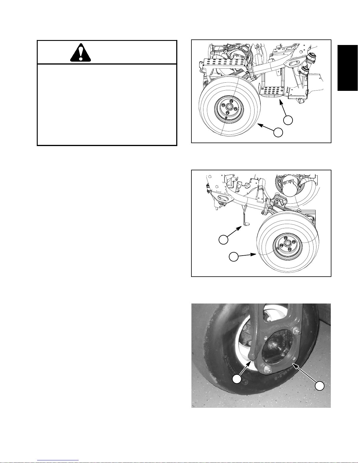
Front End Jacking
1. Apply parking brake and chock rear tire to prevent
the machine from moving.
2. Position jack securely underthe frame jacking point:
A. The left side jacking point is the frame channel
under the step behind the LH front wheel (Fig. 1).
B. The right side jacking point is the frame bracket
behind the RH front wheel (Fig. 2).
3. Jack front of machine off the ground.
Safety
2
1
Figure 1
1. LH front wheel 2. Jacking point
2
4. Position appropriate jack stands under the frame as
close to the wheel as possible to support the machine.
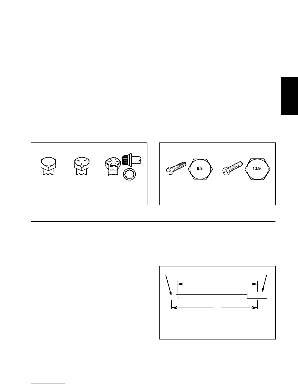
Rear End Jacking
1. Applyparkingbrakeandchock both fronttirestopre-
vent the machine from moving.
2. Place jack securely under the rear jacking point on
the rear steering fork (Fig. 3).
3. Jack rear of machine off the ground.
4. Position appropriate jack stands under the frame to
support the machine.
1
Figure 2
1. RH front wheel 2. Jacking point
2
1
Figure 3
1. Rear steering fork 2. Rear jacking point
Greensmaster 3300/3400 Page 1 -- 5 Safety
Page 12

Safety and Instruction Decals
Numerous safety and instruction decals are affixed to
the traction unit and the cutting units of Greensmaster
TriFlex3300and 3400 machines.Ifany decal becomes
illegible or damaged, install a new decal. Part numbers
are listed in your Parts Catalog and Operator’s Manual.
Order replacement decals from your Authorized Toro
Distributor.
Greensmaster 3300/3400Page 1 -- 6Safety
Page 13

Product Records and Maintenance
Table of Contents
PRODUCT RECORDS 1.........................
MAINTENANCE 1...............................
EQUIVALENTS AND CONVERSIONS 2...........
Decimal and Millimeter Equivalents 2............
U.S. to Metric Conversions 2...................
TORQUE SPECIFICATIONS 3....................
Fastener Identification 3.......................
Using a Torque Wrench with an Offset Wrench 3..
Standard Torque for Dry, Zinc Plated and
Steel Fasteners (Inch Series). 4...............
Standard Torque for Dry, Zinc Plated and
Steel Fasteners (Metric Fasteners). 5..........
Other Torque Specifications 6..................
Conversion Factors 6..........................
Chapter 2
Product Records
and Maintenance
Product Records
Inserta copy ofthe TractionUnit and CuttingUnit Operator’s Manuals and Parts Catalog for your Greensmasterat the endof this chapter.Additionally,ifanyoptional
equipment or accessories have been installed to your
machine, insert the Installation Instructions, Operator’s
ManualsandPartsCatalogsforthoseoptions at theend
of this chapter.
Maintenance
Maintenanceproceduresandrecommendedserviceintervals for your Greensmaster are covered in the Traction Unit Operator’s Manual. Maintenance procedures
andrecommendedserviceintervalsfortheGreensmaster Cutting Units are covered in the Cutting Unit Operator’s Manual. Refer to these publications when
performing regular equipment maintenance. Refer to
theEngineOperator’sManualforadditionalenginespecific maintenance procedures.
Greensmaster 3300/3400 Page 2 -- 1 Product Records and Maintenance
Page 14

Equivalents and Conversions
0.09375
Greensmaster 3300/3400Page 2 -- 2Product Records and Maintenance
Page 15
Torque Specifications
Recommended fastener torque values are listed in the
followingtables.For critical applications, as determined
byToro, either the recommended torque or a torquethat
is unique to the application is clearly identifiedand specified in this Service Manual.
These Torque Specifications for the installation and
tightening of fastenersshall apply to all fasteners which
donot have aspecific requirement identifiedin this Service Manual. The following factors shall be considered
when applying torque: cleanliness of the fastener, use
of a thread sealant (e.g. Loctite), degree of lubrication
onthe fastener,presenceof a prevailing torquefeature,
hardnessofthesurfaceunderneaththefastener’s head
or similar condition which affects the installation.
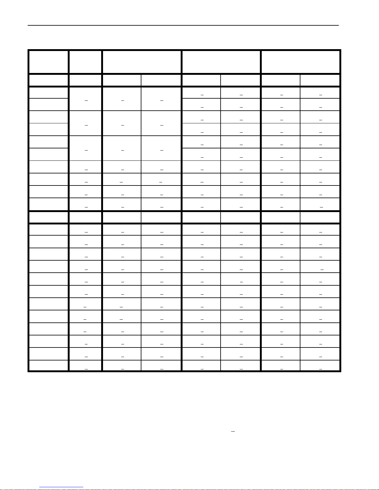
Fastener Identification
Asnotedinthe following tables,torquevaluesshouldbe
reduced by 25% for lubricated fasteners to achieve
the similar stress as a dry fastener.Torque values may
also have to be reduced when the fastener is threaded
into aluminum or brass. The specific torque value
should be determined based on the aluminum or brass
material strength, fastener size, length of thread engagement, etc.
The standard method of verifying torque shall be performed by marking a line on the fastener (head or nut)
and mating part, then back off fastener 1/4 of a turn.
Measurethetorquerequiredtotighten the fastener until
the lines match up.
Product Records
and Maintenance
Grade 1 Grade 5 Grade 8
Inch Series Bolts and Screws
Figure 1
Using a Torque Wrench with an Offset Wrench
Useofanoffsetwrench(e.g. crowfootwrench)willaffect
torquewrench calibration dueto the effective change of
torquewrenchlength.Whenusingatorque wrench with
an offset wrench, multiply the listed torque recommendation by the calculated torque conversion factor (Fig.
3) to determine proper tightening torque. Tightening
torque when using a torque wrench with an offset
wrench will be lower than the listed torque recommendation.
Example: The measured effective length of the torque
wrench (distance from the center of the handle to the
center of the square drive) is 18”.
Themeasuredeffectivelengthofthetorquewrenchwith
the offset wrench installed (distance from the center of
the handle to the center of the offset wrench) is 19”.
Class 8.8 Class 10.9
Metric Bolts and Screws
Figure 2
If the listed torque recommendation for a fastener is
from 76 to 94 ft--lb, the proper torque when using this
torque wrench with an offset wrench would be from 72
to 89 ft--lb.
(effective length of
torque wrench)
A
B
(effective length of torque
wrench + offset wrench)
TORQUE CONVERSION FACTOR = A / B
Torque wrenchOffset wrench
The calculated torque conversion factor for this torque
wrenchwiththis offset wrench would be18/ 19 = 0.947.
Greensmaster 3300/3400 Page 2 -- 3 Product Records and Maintenance
Figure 3
Page 16
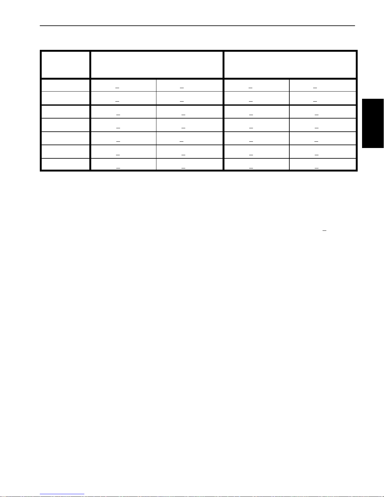
Standard Torque for Dry, Zinc Plated and Steel Fasteners (Inch Series)
Thread Size
# 6 -- 32 UNC
# 6 -- 40 UNF
# 8 -- 32 UNC
# 8 -- 36 UNF
#10--24UNC
#10--32UNF
1/4 -- 20 UNC 48 + 7 53 + 7 599 + 79 100 + 10 1125+ 100 140 + 15 1580 + 170
1/4 -- 28 UNF 53 + 7 65+ 10 734 + 113 115 + 10 1300 + 100 160 + 15 1800 + 170
5/16 -- 18 UNC 115 + 15 105 + 17 1186 + 169 200 + 25 2250 + 280 300+ 30 3390 + 340
5/16 -- 24 UNF 138 + 17 128 + 17 1446 + 192 225 + 25 2540 + 280 325 + 30 3670 + 340
3/8 -- 16 UNC 16 + 2 16 + 2 22 + 3 30 + 3 41 + 4 43 + 4 58 + 5
Grade 1, 5 &
8withThin
Height Nuts
in--lb in--lb N--cm in--lb N--cm in--lb N--cm
10 + 2 13 + 2 147 + 23
13 + 2 25 + 5 282 + 30
18 + 2 30 + 5 339 + 56
ft--lb ft--lb N--m ft--lb N--m ft--lb N--m
SAE Grade 1 Bolts, Screws, Studs &
Sems with Regular Height Nuts
(SAE J995 Grade 2 or Stronger Nuts)
SAE Grade 5 Bolts, Screws, Studs &
Sems with Regular Height Nuts
(SAE J995 Grade 2 or Stronger Nuts)
15 + 2 170 + 20 23 + 2 260 + 20
17 + 2 190 + 20 25 + 2 280 + 20
29 + 3 330 + 30 41 + 4 460 + 45
31 + 3 350 + 30 43 + 4 485 + 45
42 + 4 475 + 45 60 + 6 675 + 70
48 + 4 540 + 45 68 + 6 765 + 70
SAE Grade 8 Bolts, Screws, Studs &
Sems with Regular Height Nuts
(SAE J995 Grade 5 or Stronger Nuts)
3/8 -- 24 UNF 17 + 2 18 + 2 24 + 3 35 + 3 47 + 4 50 + 4 68 + 5
7/16 -- 14 UNC 27 + 3 27 + 3 37 + 4 50 + 5 68 + 7 70 + 7 95 + 9
7/16 -- 20 UNF 29 + 3 29 + 3 39 + 4 55 + 5 75 + 7 77 + 7 104 + 9
1/2 -- 13 UNC 30 + 3 48 + 7 65 + 9 75 + 8 102 + 11 105 + 10 142 + 14
1/2 -- 20 UNF 32 + 3 53 + 7 72 + 9 85 + 8 115 + 11 120 + 10 163 + 14
5/8 -- 11UNC 65 + 10 88 + 12 119 + 16 150 + 15 203 + 20 210 + 20 285+ 27
5/8 -- 18 UNF 75 + 10 95 + 15 129 + 20 170 + 15 230 + 20 240 + 20 325 + 27
3/4 -- 10 UNC 93 + 12 140 + 20 190 + 27 265 + 25 359 + 34 375 + 35 508 + 47
3/4 -- 16 UNF 115 + 15 165 + 25 224 + 34 300 + 25 407 + 34 420 + 35 569 + 47
7/8 -- 9 UNC 140 + 20 225 + 25 305 + 34 430 + 45 583 + 61 600 + 60 813 + 81
7/8 -- 14 UNF 155 + 25 260 + 30 353 + 41 475 + 45 644 + 61 660 + 60 895 + 81
NOTE: Reduce torque values listed in the table above
by 25% for lubricated fasteners. Lubricated fasteners
on the fastener size, the aluminum or base material
strength, length of thread engagement, etc.
are defined as threads coated with a lubricant such as
oil, graphite or thread sealant such as Loctite.
NOTE: The nominal torque values listed above for
Grade 5 and 8 fasteners are based on 75% of the miniNOTE: Torque values may have to be reduced when
installing fasteners into threaded aluminum or brass.
The specific torque value should be determined based
mumproof load specifiedin SAE J429.Thetolerance is
approximately +
10% of the nominal torque value. Thin
height nuts include jam nuts.
Greensmaster 3300/3400Page 2 -- 4Product Records and Maintenance
Page 17
Standard Torque for Dry, Zinc Plated and Steel Fasteners (Metric Fasteners)
Class 8.8 Bolts, Screws and Studs with
Thread Size Regular Height Nuts
(Class 8 or Stronger Nuts)
Class 10.9 Bolts, Screws and Studs with
Regular Height Nuts
(Class 10 or Stronger Nuts)
M5 X 0.8 57 + 5in--lb 640 + 60 N--cm 78 + 7in--lb 885 + 80 N--cm
M6 X 1.0 96 + 9in--lb 1018 + 100 N--cm 133 + 13 in--lb 1500 + 150 N--cm
M8 X 1.25 19 + 2ft--lb 26 + 3N--m 27 + 2ft--lb 36 + 3N--m
M10 X 1.5 38 + 4ft--lb 52 + 5N--m 53 + 5ft--lb 72 + 7N--m
M12 X 1.75 66 + 7ft--lb 90 + 10 N--m 92 + 9ft--lb 125+ 12 N--m
M16 X 2.0 166 + 15 ft--lb 225 + 20 N-- m 229 + 22 ft--lb 310 + 30 N--m
M20 X 2.5 325 + 33 ft--lb 440 + 45 N--m 450 + 37 ft--lb 610 + 50 N--m
NOTE: Reduce torque values listed in the table above
by 25% for lubricated fasteners. Lubricated fasteners
on the fastener size, the aluminum or base material
strength, length of thread engagement, etc.
are defined as threads coated with a lubricant such as
oil, graphite or thread sealant such as Loctite.
NOTE: The nominal torque values listed above are
NOTE: Torque values may have to be reduced when
installing fasteners into threaded aluminum or brass.
The specific torque value should be determined based
based on 75% of the minimum proof load specified in
SAEJ1199.Thetoleranceisapproximately+
nominal torque value.
10%ofthe
Product Records
and Maintenance
Greensmaster 3300/3400 Page 2 -- 5 Product Records and Maintenance
Page 18
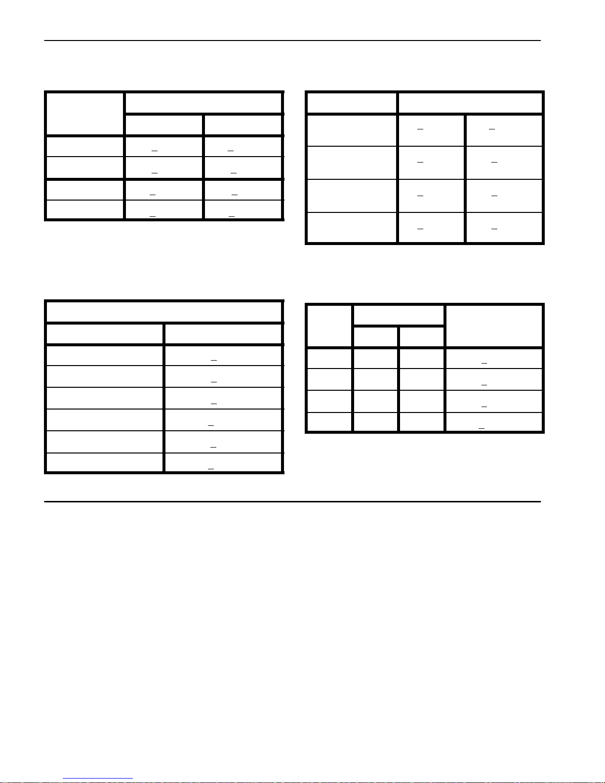
Other Torque Specifications
*
SAE Grade 8 Steel Set Screws
Recommended Torque
Thread Size
Square Head Hex Socket
1/4 -- 20 UNC 140 + 20 in--lb 73 + 12 in--lb
5/16 -- 18 UNC 215 + 35 in--lb 145 + 20 in--lb
3/8 -- 16 UNC 35 + 10 ft--lb 18 + 3ft--lb
1/2 -- 13 UNC 75 + 15 ft--lb 50 + 10 ft--lb
Thread Cutting Screws
(Zinc Plated Steel)
Type 1, Type 23 or Type F
Thread Size Baseline Torque*
No. 6 -- 32 UNC 20 + 5in--lb
Wheel Bolts and Lug Nuts
Thread Size
7/16 -- 20 UNF
Grade 5
1/2 -- 20 UNF
Grade 5
M12 X 1.25
Class 8.8
M12 X 1.5
Class 8.8
** For steel wheels and non--lubricated fasteners.
Thread Cutting Screws
(Zinc Plated Steel)
Thread
Size
No. 6 18 20 20 + 5in--lb
Threads per Inch
Type A Type B
Recommended Torque**
65 + 10 ft--lb 88 + 14 N--m
80 + 10 ft--lb 108 + 14 N--m
80 + 10 ft--lb 108 + 14 N--m
80 + 10 ft--lb 108 + 14 N--m
Baseline Torque
No. 8 -- 32 UNC 30 + 5in--lb
No. 10 -- 24 UNC 38 + 7in--lb
1/4 -- 20 UNC 85 + 15 in--lb
5/16 -- 18 UNC 110 + 20 in--lb
3/8 -- 16 UNC 200 + 100 in--lb
Conversion Factors
in--lb X 11.2985 = N--cm N--cm X 0.08851 = in--lb
ft--lb X 1.3558 = N--m N--m X 0.7376 = ft--lb
No. 8 15 18 30 + 5in--lb
No. 10 12 16 38 + 7in--lb
No. 12 11 14 85 + 15 in--lb
*Holesize,materialstrength,material thicknessandfinish must be considered when determining specific
torquevalues.Alltorque values are based onnon--lubricated fasteners.
Greensmaster 3300/3400Page 2 -- 6Product Records and Maintenance
Page 19

Table of Contents
SPECIFICATIONS 2.............................
GENERAL INFORMATION 3.....................
Operator’s Manual 3..........................
FUEL EVAPORATIVE CONTROL SYSTEM 4.......
ADJUSTMENTS 7..............................
Choke Cable Adjustment 7.....................
Throttle Cable Adjustment 7....................
SERVICE AND REPAIRS 8......................
Fuel Evaporative Control System (Serial Number
Below 312000000) 8.........................
Fuel Evaporative Control System (Serial Number
Above 312000000) 10.......................
Fuel Tank 12.................................
Engine 14....................................
Engine Removal 14..........................
Engine Installation 16........................
BRIGGS & STRATTON VANGUARD V--TWIN OHV
REPAIR MANUAL
Chapter 3
Gasoline Engine
Engine
Gasoline
Greensmaster 3300 Page 3 -- 1 Gasoline Engine
Page 20

Specifications
Item Description
Make / Designation Briggs and Stratton, 4--cycle, V--Twin Cylinder,
Bore x Stroke 2.97” x 2.76” (75.5 mm x 70 mm)
Total Displacement 38.3 in3(627 cc)
Governor Mechanical Governor
Carburetor Float Feed, Two Barrel
Fuel Pump Pulsating Crankcase Vacuum
Fuel Unleaded, regular grade gasoline
Fuel Tank Capacity 6.0 U.S. gallons (22.7 liters)
Low Idle (no load) 1650 + 100 RPM
High Idle (no load) 2920 + 50 RPM
Lubrication System Pressure Lubrication, Gear Driven Geroter Oil Pump
Engine Oil See Operator’s Manual
Crankcase Oil Capacity 1.75 U.S. quarts (1.65 liters) with new filter
OHV, Air Cooled, Gasoline Engine -- Model 385447
Ignition System Flywheel magneto, twin electronic armatures
Spark Plugs Champion RC 14YC (or equivalent)
Spark Plug Gap 0.030” (0.76 mm)
Alternator 20/50 Amp
Dry Weight (approximate) 85 lb (39 kg)
Greensmaster 3300Page 3 -- 2Gasoline Engine
Page 21

General Information
Informationaboutspecifications, maintenance, troubleshooting,testing and repair ofthegasoline engine used
in the Greensmaster TriFlex 3300 is included in this
chapter and the Briggs & Stratton Vanguard V--Twin
OHV Repair Manual.
Most engine repairs and adjustments require tools
which are commonly available in many service shops.
Special tools are described in the Briggs & Stratton Repair Manual. The use of some specialized test equipment is explained. However, the cost of the test
equipment and the specialized nature of some repairs
may dictate that the work be done at an engine repair
facility.
Operator’s Manual
The Traction Unit Operator’s Manual provides information regarding the operation, general maintenance and
maintenanceintervals for your Greensmastermachine.
Refer to the Operator’s Manual for additional information when servicing the machine.
Service and repair parts for Briggs &Stratton Vanguard
V-Twin OHV enginesare supplied through yourlocal localToro distributor.If noparts list is available,besure to
provide your distributor with the Toro model and serial
numberalongwith the engine modelandserialnumber.
Engine
Gasoline
Greensmaster 3300 Page 3 -- 3 Gasoline Engine
Page 22
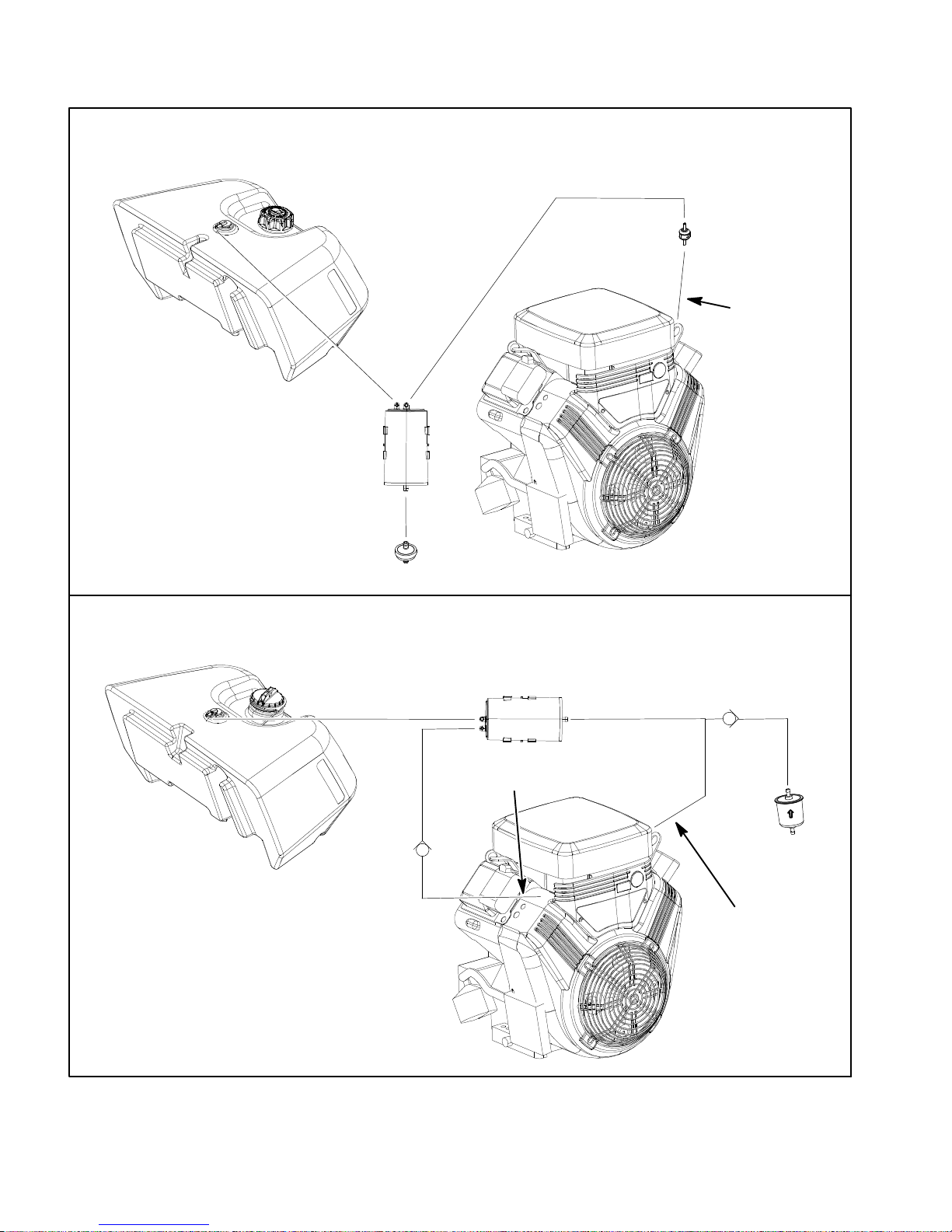
Fuel Evaporative Control System
SERIAL NUMBER BELOW 312000000
FUEL
TANK
CARBON
CANNISTER
CHECK
VALVE
TO INTAKE
MANIFOLD
ENGINE
FUEL
TANK
FRESH AIR
FILTER
SERIAL NUMBER ABOVE 312000000
CARBON
CANNISTER
TO INTAKE
MANIFOLD
CHECK
VALVE
CHECK
VALVE
FRESH AIR
FILTER
TO AIR
CLEANER
ENGINE
Figure 1
Greensmaster 3300Page 3 -- 4Gasoline Engine
Page 23

The function of the fuel evaporative control system is to
collect and store evaporative emissions from the fuel
tankandengine.Theevaporatecontrolsystem used on
Greensmaster 3300 machines uses a carbon cannister
to collect these evaporative emissions. Fuel vapors
fromthefueltankareventedtothecanisterwhentheengine is not running. Vapors from the canister are consumed when the engine is running.
Machines With Serial Number Below 312000000
Onmachines with serial number below 312000000, the
carbon canister is mounted under the fuel tank mount
plate. One fitting at the engine intake manifold is used
toconnect the evaporative systemtothe engine. These
machinesuseaninlinecheckvalvebetweenthecarbon
cannister and the engine intake manifold fitting.
The fuel tank on Greensmaster 3300 machines uses a
non--vented fuel cap. To connect the tank to the evaporative control system, a fuel vent valve is positioned in
the top of the tank that allows tank venting through the
carbon cannister.
NOTE: Ifthereisrestrictioninthefreshairfilter,thecarbon cannister or the fuel vent valve, the fuel tank may
distortduetoventing issues.Ifthefueltank returns toit’s
normal shape when the fuel cap is removed, restriction
in the evaporative control system is likely.
Components used in the evaporative controlsystem on
Greensmaster 3300 machines changed at serial number 312000000. Figure 1 illustrates the components
used in the evaporative control system.
Machines With Serial Number Above 312000000
Onmachines with serial numberabove312000000, the
carbon canister is mounted between the hydraulic reservoir and leak detector tank. The evaporative system
includestwo(2)connectionsto theengine:onetotheintake manifold and the second to the air cleaner base.
Venting hose assemblies include a check valve in two
(2) locations as shown in Figure 1.
NOTE: Thecheckvalves used onmachines with serial
numberabove312000000areincludedasacomponent
of the hose assembly and are not available as a separatepart.Toensureproperoperationofcheckvalves,do
not attempt to remove them from the hose assembly. If
either of these hose assemblies are removed, make
surethattheyare correctlyinstalledtoinsurecorrectoperation of the evaporative control system.
Engine
Gasoline
Greensmaster 3300 Page 3 -- 5 Gasoline Engine
Page 24

This page is intentionally blank.
Greensmaster 3300Page 3 -- 6Gasoline Engine
Page 25
Adjustments
Choke Cable Adjustment
1. Parkmachineonalevelsurface,disengageand lower cutting units, move functional control lever to neutral
(N),engage parking brake, stoptheengine and remove
the key from the ignition switch. Wait for all machine
movement to stop.
2. Remove air cleaner cover and air filter from engine.
3. Move choke control on control panel while watching
choke plate in carburetor.
A. Choke plate should be fully open when choke
control is pushed in.
B. Choke plate should be fully closed when choke
control is pulled out.
Throttle Cable Adjustment
1. Parkmachineonalevelsurface,disengageand lower cutting units, move functional control lever to neutral
(N),engage parking brake, stoptheengine and remove
the key from the ignition switch. Wait for all machine
movement to stop.
4. Ifcableadjustmentis needed, loosen cap screw and
nut that secure choke cable clamp. Reposition cable to
allow correct choke operation. Secure choke cable
clamp.
5. After adjustment, move choke control several times
to make sure that choke operation is correct.
6. Assemble air cleaner.
Engine
Gasoline
2. Adjustthrottle control onconsoleto the fast position.
Inspectgovernorlever onenginetomakesure thatlever
is fully rotated and against stop on governor control.
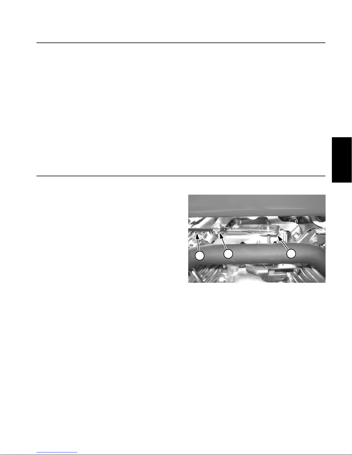
3. If throttle cable adjustment is needed (Fig. 2):
A. Loosen cap screw that secures throttle cable
clamp on engine bracket.
B. Reposition cable to allow correct governor rota-
tion.
C. Tighten screw to secure throttle cable clamp.
4. After adjustment, move throttle control on console
from low idle to high idle to make sure that cable travel
is correct.
1
1. Throttle cable
2. Cable clamp
2
Figure 2
3. Governor control lever
3
Greensmaster 3300 Page 3 -- 7 Gasoline Engine
Page 26
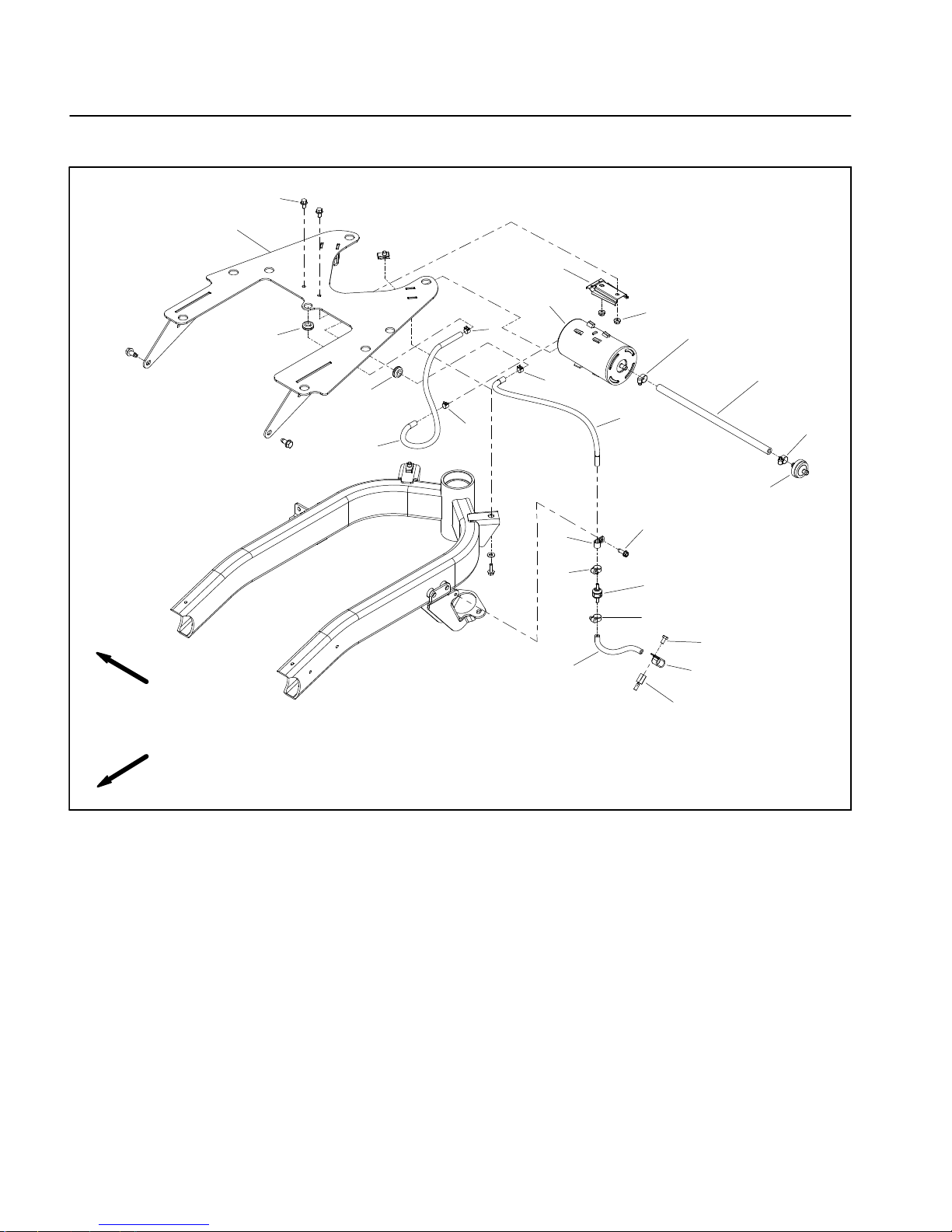
Service and Repairs
Fuel Evaporative Control System (Serial Number Below 312000000)
1
2
8
RIGHT
FRONT
7
4
4
6
6
9
19
11
10
6
19
5
12
14
13
19
15
19
16
3
17
18
1. Flange head screw (2 used)
2. Tank mount plate
3. Fuel hose (to engine intake manifold)
4. Grommet (2 used)
5. Fuel hose (cannister to tank vent)
6. Hose clamp (3 used)
7. Carbon canister
Figure 3
8. Bracket
9. Flange nut (2 used)
10. Fuel hose (cannister to check valve)
11. Fuel hose
12. Fresh air filter
13. R--clamp
14. Washer head screw
15. Check valve
16. Cap screw
17. R--clamp
18. Spacer screw (attached to engine)
19. Worm clamp (4 used)
Greensmaster 3300Page 3 -- 8Gasoline Engine
Page 27
Removal (Fig. 3)
1. Parkmachineonalevelsurface,disengageand low-
er cutting units, move functional control lever to neutral
(N),engage parking brake, stoptheengine and remove
the key from the ignition switch. Wait for all machine
movement to stop.
2
1
DANGER
Gasolineisflammable. Use cautionwhenstoring
or handling it. Do not smoke while filling the fuel
tank. Do not fill fuel tank while engine is running
or in an enclosed area. Always fill fuel tank out side and wipe up any spilled fuel before starting
the engine. Store fuel in a clean, safety--approved container and keep the cap in place. Use
gasoline for the engine only; not for any other
purpose.
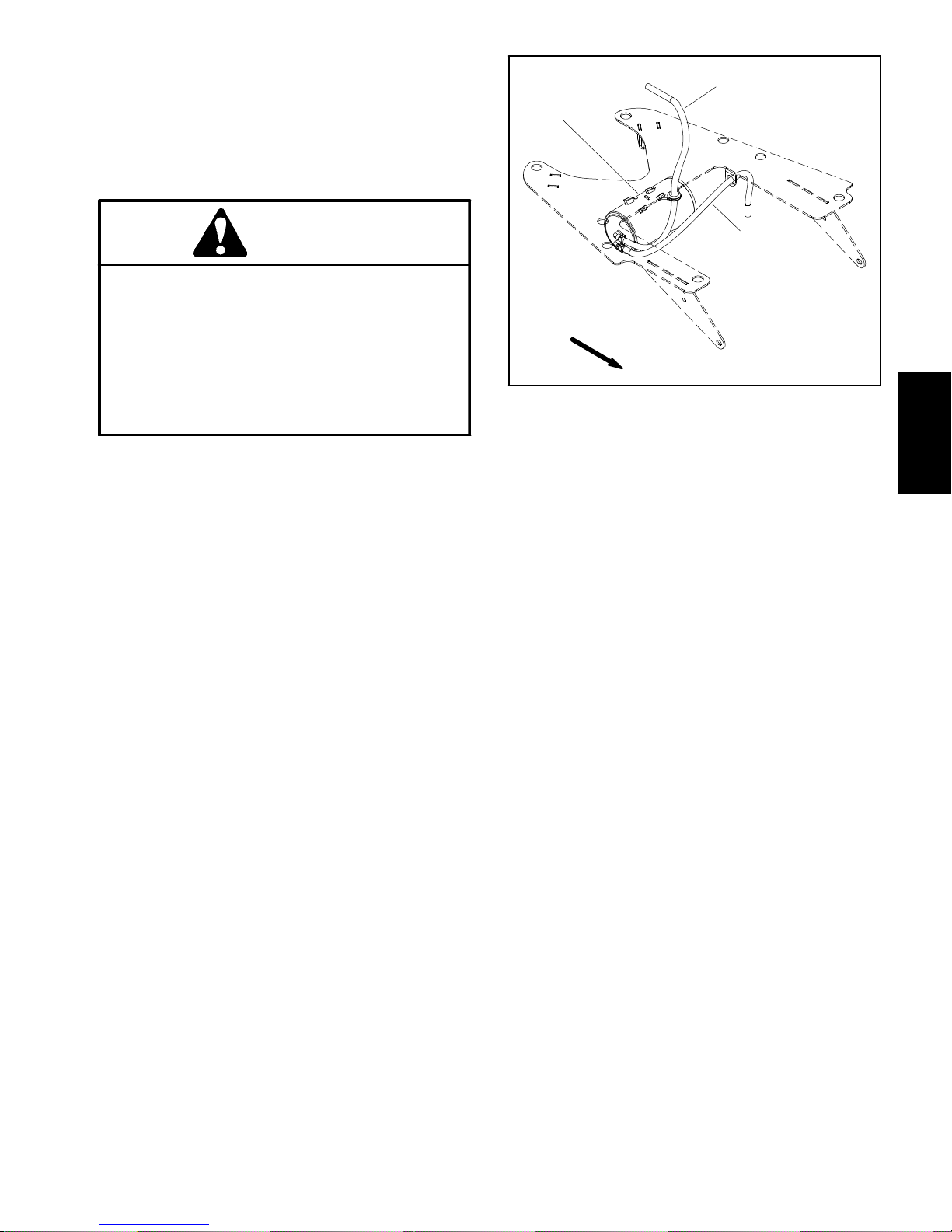
2. Access the carboncannister under thefuel tank and
betweentherearframesections. Ifnecessary,raiseand
supporttankmountplateassembly(hydraulicreservoir,
fuel tank and tank mount plate) to reach the cannister
(seeTank Mount PlateAssemblyinthe Service and Repairs section of Chapter 7 -- Chassis).
3. Inspect carbon cannister and attached for damage
or obvious leaks. A damaged or leaking cannister
should be replaced.
4. Remove components as needed using Figure 3 as
a guide.
FRONT
1. Carbon cannister
2. Hose to tank vent
Figure 4
3. Hose to engine
3
Engine
Gasoline
A. Ifcheckvalve (item15)isremoved,notedirection
of arrow on valve body for assembly purposes.
Installation (Fig. 3)
1. Install all removed components using Figure 3 as a
guide.
A. Ifcheckvalve(item 15) was removed,makesure
that arrow on valve body points toward engine.
B. Make sure that fuel hoses are not kinked after
installation.Also,secureallhoseswithhoseclamps.
2. If tank mount plate assembly (hydraulic reservoir,
fueltankandtankmountplate)wasraisedtoaccessthe
cannister,lowerand secure tank mount plate assembly
(seeTank Mount PlateAssemblyinthe Service and Repairs section of Chapter 7 -- Chassis).
Greensmaster 3300 Page 3 -- 9 Gasoline Engine
Page 28
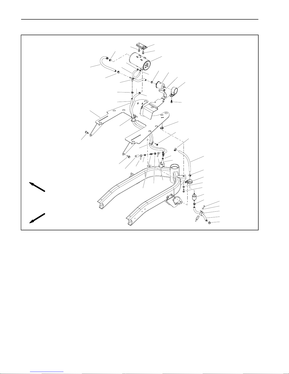
Fuel Evaporative Control System (Serial Number Above 312000000)
RIGHT
FRONT
14
1
8
1
7
6
31
14
29
32
28
21
27
29
29
30
6
9
12
11
2
24
4
5
10
3
22
20
13
35
3
34
18
20
14
15
25
26
16
14
23
33
29
18
25
19
17
14
1. Flange head screw (2 used)
2. Tank mount plate
3. Washer head screw (2 used)
4. Grommet (2 used)
5. Washer head screw
6. Hose clamp (2 used)
7. Carbon cannister
8. Cannister bracket
9. Flange nut
10. Worm clamp
11. Cap screw
12. R--clamp
The function of the fuel evaporative control system is to
collect and store evaporative emissions from the fuel
tankandengine.Onmachineswithserialnumberabove
312000000, a carbon canister mounted above the hydraulicreservoirisused tocollectcollecttheseevaporative emissions. Fuel vapors from the engine and fuel
tank are vented to the canister when the engine is not
running. Vaporsfrom the canister are consumed when
the engine is running.
Figure 5
13. Fuel hose (fuel supply)
14. Hose clamp (5 used)
15. R--clamp
16. Fuel filter (fuel supply)
17. Fuel hose (fuel supply)
18. Label (air cleaner)
19. R--clamp
20. Hose clamp (2 used)
21. Fuel hose (to vent valve on fuel tank)
22. R--clamp
23. Cap screw
24. Clip (2 used)
NOTE: The purge hose assembly (item 27) and tee
hose assembly (item 28) both include a check valve as
a component of the assembly. The check valve is not
available as a separate part. If either of these hose assembliesareremoved,makesurethattheyarecorrectly
installed to insure correct operation of the evaporative
control system.
25. Flat washer (3 used)
26. Flange head screw (2 used)
27. Purge hose assembly (see NOTE)
28. Tee hose assembly (see NOTE)
29. Hose clamp (4 used)
30. Fresh air filter
31. Fuel hose
32. Fuel hose
33. Barbed fitting
34. Engine hose (to air cleaner)
35. Engine hose (to intake manifold)
Greensmaster 3300Page 3 -- 10Gasoline Engine
Page 29
Removal (Fig. 5)
Installation (Fig. 5)
1. Parkmachineonalevelsurface,disengageand low-
er cutting units, move functional control lever to neutral
(N),engage parking brake, stoptheengine and remove
the key from the ignition switch. Wait for all machine
movement to stop.
DANGER
Gasolineisflammable. Use cautionwhenstoring
or handling it. Do not smoke while filling the fuel
tank. Do not fill fuel tank while engine is running
or in an enclosed area. Always fill fuel tank out side and wipe up any spilled fuel before starting
the engine. Store fuel in a clean, safety--approved container and keep the cap in place. Use
gasoline for the engine only; not for any other
purpose.
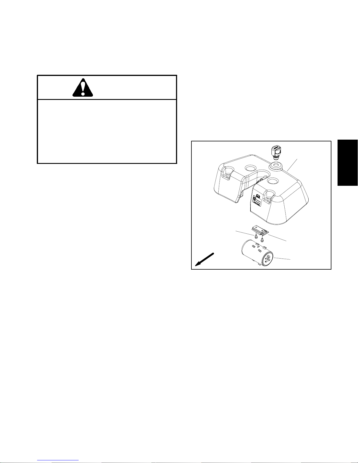
2. Remove leak detector tank (machines with Turf
Guardian
voircover(machineswithoutTurfGuardian
tector System) to gain access to carbon cannister (see
Service and Repairs section of Chapter 5 -- Hydraulic
System).
TM
Leak Detector System) or hydraulic reser-
TM
LeakDe-
1. Install all removed components using Figure 5 as a
guide.
A. If either purge hose assembly (item 27) or tee
hose assembly (item 28) was removed, make sure
that installation is correct.
B. Make sure that fuel hoses are not kinked after
installation.Also,secureallhoseswithhoseclamps.
2. Install leak detector tank (machines with Turf Guar-
TM
dian
cover (machines without Turf Guardian
Leak Detector System) or hydraulic reservoir
TM
Leak Detector System) (see Service and Repairs section of Chapter 5 -- Hydraulic System).
4
Engine
Gasoline
3. Inspect carbon cannister and attached hoses for
damageorobvious leaks.Adamagedorleakingcannister should be replaced.
4. Remove components as needed using Figure 5 as
a guide.
A. If either purge hose assembly (item 27) or tee
hoseassembly(item28)istoberemoved,labelends
of hose for assembly purposes. Both of these assembliesincludea check valve sodirectionofinstallation is important for correct operation of the
evaporative control system. The check valve is not
available as a separate part so hose assembly replacement is necessary if the check valve or hose is
faulty. To ensure proper operation of check valves,
donotattempttoremovethemfromthehose assembly.
2
FRONT
1. Carbon cannister
2. Screw (2 used)
3
1
Figure 6
3. Cannister bracket
4. Leak detector tank
Greensmaster 3300 Page 3 -- 11 Gasoline Engine
Page 30

Fuel Tank
Illustration from machine with serial
number below 312000000 shown
5
2
3
33
34
35
Antiseize
Lubricant
30 to 50 in--lb
(3.4 to 5.6 N--m)
3
RIGHT
FRONT
31
32
27
28
23
22
30
29
1
24
8
6
9
7
10
6
10
4
5
13
14
5
18
11
10
12
15
19
25
26
14
16
10
20
10
21
1. Flange head screw (2 used)
2. Tank mount plate
3. Washer head screw (2 used)
4. Grommet (2 used)
5. Fuel hose (2 used)
6. Hose clamp (3 used)
7. Carbon cannister
8. Bracket
9. Flange nut (2 used)
10. Worm clamp (5 used)
11. Fuel hose
12. Fresh air filter
Figure 7
13. Fuel supply hose
14. Hose clamp (3 used)
15. R--clamp
16. Fuel filter
17. Fuel hose
18. Clamp
19. Washer head screw
20. Check valve
21. Fuel hose
22. Fuel tank
23. Fuel tank cap
24. Clip (2 used)
17
14
25. Flat washer (2 used)
26. Flange head screw (2 used)
27. Fitting (LH thread)
28. O--ring
29. Shut--off valve
30. Nut (LH thread)
31. Fuel vent valve
32. Grommet
33. Flange bushing (4 used)
34. Washer (4 used)
35. Cap screw (4 used)
Greensmaster 3300Page 3 -- 12Gasoline Engine
Page 31

Fuel Tank Removal (Fig. 7)
Fuel Tank Installation (Fig. 7)
1. Parkmachineonalevelsurface,disengageand lower cutting units, move functional control lever to neutral
(N),engage parking brake, stoptheengine and remove
the key from the ignition switch. Wait for all machine
movement to stop.
CAUTION
The muffler and exhaust manifold may be hot.
Avoid possible burns, allow exhaust system to
cool before working on the engine.
DANGER
Gasolineisflammable. Use cautionwhenstoring
or handling it. Do not smoke while filling the fuel
tank. Do not fill fuel tank while engine is running
or in an enclosed area. Always fill fuel tank out side and wipe up any spilled fuel before starting
the engine. Store fuel in a clean, safety--approved container and keep the cap in place. Use
gasoline for the engine only; not for any other
purpose.
2. Drain fuel tank:
1. Install fitting assembly and shut--off valve into fuel
tankiftheywere removedfromtank(Fig.8). Thenutand
fitting have left hand threads.
2. Position fuel tank on the tank mount plate.
3. Secure fuel tank to tank mount plate:
A. Applyantiseizelubricantto the threadsofthefour
(4) cap screws (item 35).
B. Securefuel tank tothe tank mountplate with four
(4) cap screws (item 35), flat washers (item 34) and
flange bushings (item 33).
C. Torque cap screws from 30 to 50in--lb(3.4to5.6
N--m).
4. Install fuel supply hose (item 13) to fuel shut--off
valve and fuel filter. Secure supply hose with hose
clamps.
5. Connectfuelhose(item5)tofuelventvalve(item31)
and secure with hose clamp.
6. Fill fuel tank with fuel.
7. Open fuel shut--off valve. Check all fuel hoses and
fuel tank for leaks.
Engine
Gasoline
A. Close fuel shut--off valve (item 29).
B. Disconnect fuel supply hose (item 13) at the fuel
filter (item 16) and drain any fuel trapped in the fuel
filter and fuel hose into a suitable container.
C. Placeendoffuel hoseintoasuitablecontainerfor
draining the tank.
D. Drain fuel tank by opening the fuel shutoff valve.
3. Remove fuel hose (item 5) from fuel vent valve (item
31).
4. Remove four (4) cap screws (item 35), flat washers
(item 34) and flange bushings (item 33) that secure the
fuel tank to the tank mount plate (item 2). Remove the
fuel tank from the machine.
5. Ifnecessary,remove fuel supplyhose(item13) from
fuel shut--off valve.
6. If necessary, remove shut--off valve and fitting assembly from fuel tank (Fig. 8). The nut and fitting have
left hand threads.
1. Shut--off valve
2. Nut (LH thread)
3
2
1
4
Figure 8
3. Fitting (LH thread)
4. O--ring
Greensmaster 3300 Page 3 -- 13 Gasoline Engine
Page 32

Engine
20 to 25 in--lb
(2.3 to 2.8 N--m)
7
90 to 110 in--lb
1
Antiseize
Lubricant
2
3
10
6
25
20
22
4
8
9
8
11
26
5
12
(10.2 to 12.4 N--m)
21
23
24
14
25 to 38 ft--lb
(34to51N--m)
170 to 200 in--lb
(19.3 to 22.6 N--m)
19
13
15
16
FRONT
RIGHT
1. Engine assembly
2. Spacer screw
3. Muffler
4. Muffler mount
5. Cap screw (4 used)
6. Flange nut (4 used)
7. Muffler shield
8. Hardened washer (8 used)
9. Cap screw (4 used)
10. Muffler clamp
11. Lock nut (4 used)
12. Pump mount
13. Cap screw (4 used)
14. Exhaust manifold
15. Gasket (2 used)
16. Flange head screw (4 used)
17. Engine frame
18. Flange head screw (3 used)
Engine Removal (Fig. 9)
1. Parkmachineonalevelsurface,disengageand lower cutting units, move functional control lever to neutral
(N),engage parking brake, stoptheengine and remove
the key from the ignition switch. Wait for all machine
movement to stop.
CAUTION
The engine and exhaust system may be hot.
Avoid possible burns, allow engine and exhaust
system to cool before working on the engine.
Figure 9
17
19. Square key
20. Engine hub
21. Square head screw (2 used)
22. Rubber coupling
23. Coupling spacer (2 used)
24. Flange head screw (2 used)
25. Lock washer
26. Flat washer (4 used)
18
DANGER
Gasolineisflammable. Use cautionwhenstoring
or handling it. Do not smoke while filling the fuel
tank. Do not fill fuel tank while engine is running
or in an enclosed area. Always fill fuel tank out side and wipe up any spilled fuel before starting
the engine. Store fuel in a clean, safety--approved container and keep the cap in place. Use
gasoline for the engine only; not for any other
purpose.
Greensmaster 3300Page 3 -- 14Gasoline Engine
Page 33

2. Disconnect the negative (--) battery cable at the battery.
3. Close fuel shut--off valve on fuel tank.
4. Disconnect fuel hoses from the fuel filter outlet and
thecheckvalve nearrearenginecylinderhead (Fig.10).
Drainany fuel trappedin the fuel filterand fuel hoseinto
a suitable container.
3
2
5. Disconnect choke and throttle control cables from
engine.
6. Loosen and remove cap screw (item 5), flat washer
(item 26), lock washer (item 25) and flange nut (item 6)
that secure wire harness ground connectors to engine
assembly (Fig. 11).
7. Disconnect wire harness connectors from engine
components:
NOTE: Beforedisconnectingwireharnessconnectors,
label all electrical leads for assembly purposes.
A. Alternator (from regulator/rectifier) (Fig. 11)
B. Fuel solenoid (Fig. 11)
C. Magneto (Fig. 11)
D. Oil pressure switch (next to oil filter)
E. Starter motor (Fig. 11)
F. Ground wire at rear muffler mount screw
4
1. Fuel filter
2. Check valve
3
1
4
Figure 10
3. Rear cylinder head
4. Fuel pump
1
Engine
Gasoline
2
8. Loosen the two (2) square head screws (item 21)
thatsecuretheenginehub(item20)totheenginecrankshaft.
9. Supportthe engine assembly topreventit from shifting or falling.
10.Remove four (4) cap screws (item 13) that secure
engine assembly to pump mount (item 12).
IMPORTANT: Make sure to not damage the engine,
fuel lines, hydraulic hoses, electrical harness, controlcablesorother parts whileremovingtheengine.
11.Carefully move the engine assembly away from the
pumpmounttoslidetheengine crankshaft out oftheenginehub(item 20). Once thecrankshafthas cleared the
hub, remove the engine from the machine.
12.Locateandretrievesquare key(item19)fromengine
crankshaft.
13.If necessary, remove exhaust system components
from engine using Figure 9 as a guide.
1. Ground connectors
2. Alternator wire
3. Fuel solenoid wire
1. Piston (traction) pump
2. Pump mount
Figure 11
4. Magneto wire
5. Starter motor cable
1
Figure 12
3. Engine hub
4. Rubber coupling
5
3
4
2
Greensmaster 3300 Page 3 -- 15 Gasoline Engine
Page 34

Engine Installation (Fig. 9)
1. Make sure that all removed engine components are
correctly installed to the engine.
2. If exhaust system components were removed from
engine, attach removed components using Figure 9 as
a guide.
3. Apply antiseize lubricantto engine crankshaft. Position square key (item 19) to crankshaft.
IMPORTANT: Make sure to not damage the engine,
fuel hose, hydraulic hoses, electrical harness, controlcablesorotherpartswhileinstallingtheengine.
4. Aligntheenginehub(item20)withtheenginecrankshaft and square key.
5. While supporting the engine to prevent damaging
thepump coupling, carefullymove the engineso crankshaftslidesintotheenginehub(item20)and toward the
pump mount. Once the engine contacts the pump
mount,alignmounting holesandsecureengineto pump
mount with four (4) cap screws (item 13). Torque cap
screws from 25 to 38 ft--lb (34 to 51 N--m).
7. Securewireharnessgroundconnectortoengine assembly with cap screw (item 5), flat washer (item 26),
lock washer (item 25) and flange nut (item 6) (Fig. 11).
Make sure that lock washer is positioned between
ground connector and engine flange to ensure ground
connection to engine.
8. Connect all wire harness connectors to correct engine components.
9. Connectandadjustthechoke control cable (see Adjusting the Choke Control in the Adjustments section of
this chapter).
10.Connect and adjust the throttle control cable (see
Adjusting the Throttle Control in the Adjustments section of this chapter).
11.Connect fuel hoses to the fuel filter outlet and check
valve near rear engine cylinder head (Fig. 10). Secure
hoses with hose clamps.
12.Openfueltankshut--offvalveandcheck fuelhosefor
leaks.
13.Check engine oil level and adjust if necessary.
6. Make sure that rubber coupling (item 22) is not distorted.Secureenginehubto engine crankshaft with two
(2) square head screws (item 21). Torque screws from
90 to 110 in--lb (10.2 to 12.4 N--m).
14.Start the engine and check for proper operation.
Greensmaster 3300Page 3 -- 16Gasoline Engine
Page 35

Table of Contents
SPECIFICATIONS 2.............................
GENERAL INFORMATION 3.....................
Operator’s Manual 3..........................
ADJUSTMENTS 5..............................
Adjust Throttle Control 5.......................
SERVICE AND REPAIRS 6......................
Air Cleaner Assembly 6........................
Exhaust System 8............................
Fuel Tank 10.................................
Radiator 12..................................
Engine 14....................................
Engine Removal 14..........................
Engine Installation 16........................
Engine Bell Housing 18........................
KUBOTA WORKSHOP MANUAL, DIESEL ENGINE,
SM--E3B SERIES
Chapter 4
Diesel Engine
Diesel
Engine
Greensmaster 3400 Page 4 -- 1 Diesel Engine
Page 36

Specifications
Item Description
Make / Designation Kubota water--cooled, Diesel,
Number of Cylinders 3
Bore x Stroke 2.83” x 2.9” (72mm x 73.6mm)
Total Displacement 54.8 in3(898 cc)
Compression Ratio 24.0:1
Firing Order 1 (closest to gear case end) -- 2 -- 3 (closest to flywheel end)
Direction of Rotation Counterclockwise (viewed from flywheel)
Fuel Diesel or Biodiesel (up to B20) Fuel with
Low or Ultra Low Sulfur Content
Fuel Injector Pump Bosch MD Type Mini
Fuel Injection Nozzle Bosch Throttle Type
Fuel Capacity 6.0 U.S. gallons (22.7 liters)
Governor Centrifugal Mechanical
Model D902--E3B
Low Idle (no load) 1500+150/--100 RPM
High Idle (no load) 2880 + 50 RPM
Engine Oil API CH--4, CI--4 or higher
Engine Oil Viscosity See Operator’s Manual
Oil Pump Gear Driven Trochoid Type
Crankcase Oil Capacity 3.9 U.S. quarts (3.7 liters) with filter
Cooling System Capacity (including reserve tank) 4.9 U.S. quarts (4.6 liters)
Starter 12 VDC 1.2 KW
Alternator/Regulator 12 VDC 60 AMP
Dry Weight (approximate) 159 lbs (72 kg)
Greensmaster 3400Page 4 -- 2Diesel Engine
Page 37

General Information
Informationaboutspecifications, maintenance, troubleshooting, testing andrepair ofthe diesel engine used in
theGreensmaster TriFlex 3400 is included in this chapter and the Kubota Workshop Manual, Diesel Engine,
SM--E3B Series.
Most engine repairs and adjustments require tools
which are commonly available in many service shops.
Special tools are described in the Kubota Workshop
Manual. The use of some specialized test equipment is
explained. However, the cost of the test equipment and
the specialized nature of some repairs may dictate that
the work be done at an engine repair facility.
Operator’s Manual
The Traction Unit Operator’s Manual provides information regarding the operation, general maintenance and
maintenanceintervals for your Greensmastermachine.
Refer to the Operator’s Manual for additional information when servicing the machine.
Service and repair parts for Kubota engines are supplied through yourlocal localToro distributor.Ifno parts
list is available, be sure to provide your distributor with
the Toro model and serial number.
Diesel
Engine
Greensmaster 3400 Page 4 -- 3 Diesel Engine
Page 38

This page is intentionally blank.
Greensmaster 3400Page 4 -- 4Diesel Engine
Page 39

Adjustments
Adjust Throttle Control
Proper throttle operation is dependent upon proper adjustment of throttle control. Make sure throttle control is
operating properly.
NOTE: The throttle cable swivel should be positioned
in the lowest hole in the speed control lever.
1. Move throttle control lever on control console to
FAST position.
2. Check position of the engine speed control lever on
fuel injection pump (Fig. 1). The speed control lever
should be contacting the high speed screw when the
throttle control lever is in the FAST position.
3. Ifnecessary,throttlecontrolcanbeadjustedbylooseningcablejamnutsandrepositioningcontrolcableuntil speed control lever contacts high speed screw when
the throttle control lever is in the FAST position (Fig. 2).
Tightencable jam nuts after adjustment has been completed.
3
1
1. High speed screw
2. Speed control lever
1
1. Throttle cable
2. Speed control lever
Figure 1
3
Figure 2
2
3. Fuel solenoid
2
3. Cable jam nut
4. Throttle cable swivel
Diesel
Engine
4
Greensmaster 3400 Page 4 -- 5 Diesel Engine
Page 40

Service and Repairs
Air Cleaner Assembly
RIGHT
FRONT
1
7
2
3
4
6
8
1. Air inlet hood
2. Flat washer (2 used)
3. Cap screw (2 used)
5
6
9
Figure 3
4. Mounting bracket
5. Air cleaner assembly
6. Hose clamp (2 used)
7. Flange nut (2 used)
8. Air intake hose
9. R--clamp
Greensmaster 3400Page 4 -- 6Diesel Engine
Page 41

Air Cleaner Removal (Fig. 3)
1. Park machine on a level surface, lower the cutting
units, stop the engine, engage parking brake and remove the key from the ignition switch.
2. Remove air cleaner components as needed using
Figure 3 as a guide.
3. Check air intake hose (item 8) for damage or wear.
Replace hose if damage is found.
5
4. Disassemble air cleaner as necessary (Fig. 4).
5. Checkaircleaner housingandcoverfordamagethat
could cause possible air leaks.
Air Cleaner Installation (Fig. 3)
IMPORTANT: Any leaks in the air cleaner system
will allow dirt into engine and will cause serious engine damage. Make sure that all air cleaner components are in good condition and are properly
secured during assembly.
1. Assemble air cleaner system using Figures 3 and 4
as guides.
A. Ifplugwasremoved from aircleanerhousing,apply sealant to threads of plug before assembly.
B. Make sure that vacuator valve on air cleaner assembly is pointed down after assembly.
C. Make sure thatair intake hose(item 8) has clearance around it at all points after air cleaner installation is completed.
1
1. Housing
2. Filter element
3. Cover
2
3
Figure 4
4. Vacuator valve
5. Plug
4
Diesel
Engine
Greensmaster 3400 Page 4 -- 7 Diesel Engine
Page 42

Exhaust System
FRONT
RIGHT
3
13
15
11
5
9
7
8
17
4
13
14
6
16
10
16
13
3
2
6
12
1
18
1. Engine assembly
2. Muffler assembly
3. Lock nut (4 used)
4. Exhaust pipe
5. Flange head screw
6. Flange nut (4 used)
Figure 5
7. Lock washer (3 used)
8. Exhaust plate
9. Exhaust gasket
10. Flange nut
11. Flange nut
12. Brace
13. Flat washer (8 used)
14. Cap screw (4 used)
15. Brace
16. Spring (4 used)
17. Muffler shield
18. Flange head screw
Greensmaster 3400Page 4 -- 8Diesel Engine
Page 43

Exhaust System Removal (Fig. 5)
Exhaust System Installation (Fig. 5)
1. Park machine on a level surface, lower the cutting
units, stop the engine, engage parking brake and remove the key from the ignition switch.
CAUTION
The muffler and exhaust pipe may be hot. To
avoid possible burns, allow the engine and exhaust system to cool before workingon the muffler.
2. Removeexhaustsystemcomponentsasneededusing Figure 5 as a guide.
NOTE: Mufflerassemblyis secured tobrackets on piston(traction)pumpwith lock nuts (item 3)andflatwashers (item 13).
1. Make sure the engine is off.
IMPORTANT: If exhaust studs were removed from
engine cylinder head, thoroughly clean threads in
head and apply Loctite #277 (or equivalent) to stud
threads before installing studs into head.
NOTE: Make sure exhaust plate and engine exhaust
manifold sealing surfaces are free of debris or damage
that may prevent a tight seal.
2. If exhaust gasket (item 9) was removed, place new
exhaust gasket on the engine exhaust manifold.
NOTE: To ensure proper exhaust system sealing,
mount all exhaust system components loosely before
fully tightening any fastener.
3. Assemble all removed exhaust system components
using Figure 5 as a guide.
4. Afterallexhaustcomponentshavebeenassembled,
make sure that all fasteners are properly tightened.
Diesel
Engine
Greensmaster 3400 Page 4 -- 9 Diesel Engine
Page 44

Fuel Tank
5
6
7
11
10
1
8
RIGHT
FRONT
1. Fuel tank
2. Tank mount plate
3. Flange head screw (4 used)
4. Clip (2 used)
5. Fuel cap
6. Fuel vent valve
2
3
4
9
11
12
13
14
3
15
Antiseize
Lubricant
30 to 50 in--lb
(3.4 to 5.6 N--m)
16
17
Figure 6
7. Grommet
8. Bushing
9. Elbow fitting
10. Vent hose
11. Hose clamp
12. Flange bushing (4 used)
13. Flat washer (4 used)
14. Cap screw (4 used)
15. Return hose
16. Hose clamp
17. Fuel supply hose
Fuel Tank Removal (Fig. 6)
1. Parkmachineonalevelsurface,disengageand lower cutting units, move functional control lever to neutral
(N),engage parking brake, stoptheengine and remove
the key from the ignition switch. Wait for all machine
movement to stop.
CAUTION
The muffler and exhaust manifold may be hot.
Avoid possible burns, allow exhaust system to
cool before working on the engine.
Greensmaster 3400Page 4 -- 10Diesel Engine
Page 45

2. Position fuel tank on the tank mount plate.
DANGER
Diesel fuel is flammable. Use caution when storing or handling it. Do not smoke while filling the
fuel tank. Do not fill fuel tank while engine is running or in an enclosed area. Always fill fuel tank
outsideand wipe up any spilledfuel before starting the engine. Store fuel in a clean, safety--approved container and keep the cap in place.
2. Drain fuel tank:
A. Close fuel shut--off valve on bottom of fuel tank.
B. Disconnect fuel supply hose (item 17) at the fuel
filter and drain any fuel trapped in the fuel filter and
fuel hose into a suitable container.
C. Placeendoffuel hoseintoasuitablecontainerfor
draining the tank.
D. Drain fuel tank by opening the fuel shutoff valve.
3. To allow easier access to fasteners that secure fuel
tank, raise and support tank mount plate assembly (hydraulic reservoir, fuel tank and tank mount plate) (see
Tank Mount Plate Assembly in the Service andRepairs
section of Chapter 7 -- Chassis).
3. Move fuel tank towards the rear of the machine and
install return hose (item 15) to elbow fitting on front of
tank. Secure hose with hose clamp.
4. Secure fuel tank to tank mount plate:
A. Applyantiseizelubricantto the threadsofthefour
(4) cap screws (item 14).
B. Securefuel tank tothe tank mountplate with four
(4) cap screws (item 14), flat washers (item 13) and
flange bushings (item 12).
C. Torque cap screws from 30 to 50in--lb(3.4to5.6
N--m).
5. Lower and secure tank mount plate assembly (hy-
draulic reservoir, fuel tank and tank mount plate) (see
Tank Mount Plate Assembly in the Service andRepairs
section of Chapter 7 -- Chassis).
6. Connect fuel supply hose (item 17) to the fuel shut--
off valve and fuel filter. Secure supply hose with hose
clamps.
7. Connect vent hose (item 10) to fuel vent valve (item
6) and secure with hose clamp.
8. Fill fuel tank with fuel.
Diesel
Engine
4. Remove vent hose (item 10) from fuel vent valve
(item 6).
5. Remove four (4) cap screws (item 14), flat washers
(item 13) and flange bushings (item 12) that secure the
fuel tank to the tank mount plate (item 2).
6. Move fuel tank towards the rear of the machine to
gainaccessto fuelreturnhose(item15). Removereturn
hose from elbow fitting on front of tank.
7. Remove the fuel tank from the machine.
8. If necessary, remove fuel supply hose from shut--off
valve.
9. If necessary, remove shut--off valve and fitting assembly from fuel tank (Fig. 7). The nut and fitting have
left hand threads.
Fuel Tank Installation (Fig. 6)
1. Install fitting assembly and shut--off valve into fuel
tankiftheywere removedfromtank(Fig.7). Thenutand
fitting have left hand threads.
9. Open fuel shut--off valve. Check all fuel hoses and
fuel tank for leaks.
3
2
1
4
Figure 7
1. Shut--off valve
2. Nut (LH thread)
3. Fitting (LH thread)
4. O--ring
Greensmaster 3400 Page 4 -- 11 Diesel Engine
Page 46

Radiator
22
18
25
20
23
24
7
20
16
8
5
3
6
20
1
16
16
6
2
17
19
21
4
16
20
14
RIGHT
FRONT
1. Seal panel
2. Radiator shroud
3. Trim seal
4. Fan assembly
5. Radiator assembly
6. Hose clamp (2 used)
7. R--clamp (2 used)
8. Clip (8 used)
9. Stud (2 used)
16
8
13
12
Figure 8
10. Stud retainer (2 used)
11. Receptacle (2 used)
12. Cap screw (4 used)
13. Flat washer (4 used)
14. R--clamp
15. Screen
16. Flange head screw (12 used)
17. Lock nut (4 used)
11
18. Flange head screw (4 used)
19. Front shroud
20. Flange nut (12 used)
21. Lower radiator hose
22. Upper radiator hose
23. Breather hose (to thermostat)
24. Overflow hose (to overflow tank)
25. Fuel pump assembly
9
10
15
Greensmaster 3400Page 4 -- 12Diesel Engine
Page 47

Radiator Removal (Fig. 8)
1. Park machine on a level surface, lower the cutting
units, stop the engine, engage parking brake and remove the key from the ignition switch.
10.Disconnect fan wire connector from machine wire
harness.
11.Support radiator assembly to prevent it from falling.
12.Remove four (4) flangenutsthatsecurefrontshroud
to machine. Remove radiator assembly from machine.
CAUTION
DO NOT open radiator cap or drain coolant if the
engineorradiatorishot. Pressurized hot coolant
can escape and cause burns.
Ethylene--gycol antifreeze is poisonous. Disposeofitproperlyorstoreitinaproperlylabeled
container away from children and pets.
2. Remove the radiator cap.
3. Drain radiator into a suitable container by disconnecting lower radiator hose from the radiator.
4. Remove screen (item 15) from radiator shroud.
5. Remove four (4) flange head screws (item 16) that
secure radiator shroud (item 2) to radiator assembly.
Remove radiator shroud.
6. Remove flange head screw that secures R--clamp
(item 14) to bottom of front shroud (item 19).
7. Remove the following hoses from the radiator:
A. Loosen hose clamps and disconnect breather
hose (item 23) and overflow hose (item 24) from radiator filler neck.
13.Removecomponentsfromr adiator asnecessaryusing Figure 8 as a guide.
Radiator Installation (Fig. 8)
1. Assembleall removed components toradiatorusing
Figure 8 as a guide.
2. Position radiator assembly to machine.Secure front
shroud to machine with four (4) flange nuts.
3. Position fuel pump assembly to radiator assembly
and secure with flange head screw and flange nut.
4. Connect fan wire connector to machine wire harness.
5. Slidefuelreturnhosethroughbothr--clamps(item7)
onfront shroud (item19). Connect return hose sections
at splice fitting and secure with hose clamp.
6. Connect the following hoses to the radiator and secure with hose clamps:
A. Upper and lower radiator hoses (items 22 and
21).
B. Breather hose (item 23) and overflow hose (item
24) to radiator filler neck.
Diesel
Engine
B. Loosenhose clamps (item6) and disconnectupper and lower radiator hoses (items 22 and 21).
8. Locate splice fitting in fuel return hose near fuel
pump. Disconnect one of the return hose sections from
splicefittingandremovereturnhose frombothr--clamps
(item 7) on front shroud (item 19).
9. Remove flange head screw and flange nut that se-
cure fuel pump assembly to front shroud. Position fuel
pump assembly away from radiator assembly.
Greensmaster 3400 Page 4 -- 13 Diesel Engine
7. Secure R--clamp (item 14) to bottom of front shroud
(item 19).
8. Secureradiatorshroud (item 2) to radiatorassembly
with four (4) flange head screws (item 16).
9. Install screen (item 15) to radiator shroud.
10.Fill radiator with coolant. Check radiator and hoses
for leaks.
Page 48

Engine
FRONT
18
26
RIGHT
28
24
21
22
27
3
13
15
17
22
11
4
5
9
7
8
13
14
6
23
16
25
10
16
13
3
2
6
1
20
12
18
19
1. Engine assembly
2. Muffler assembly
3. Lock nut (4 used)
4. Exhaust pipe
5. Flange head screw
6. Flange nut (4 used)
7. Lock washer (3 used)
8. Exhaust plate
9. Exhaust gasket
10. Flange nut
11. Flange nut
12. Brace
13. Flat washer (8 used)
14. Cap screw (4 used)
15. Brace
16. Spring (4 used)
17. Muffler shield
18. Flange head screw
19. Alternator assembly
Engine Removal (Fig. 9)
1. Parkmachineonalevelsurface,disengageand lower cutting units, move functional control lever to neutral
(N),engage parking brake, stoptheengine and remove
the key from the ignition switch. Wait for all machine
movement to stop.
Figure 9
20. V--belt
21. Fuel/water separator
22. Cap screw (2 used)
23. Engine support
24. Cap screw (4 used)
25. Lock washer (4 used)
26. Lock washer (ground connection)
27. Rear engine mount
28. R--clamp (air intake hose)
CAUTION
The engine, radiator, exhaust system and hydraulic system may be hot. T oavoid possible injury,allowmachinetocoolbefore working on the
engine.
Greensmaster 3400Page 4 -- 14Diesel Engine
Page 49

2. Close fuel shut--off valve on fuel tank.
3. Remove air cleaner and air intake hose from ma-
chine (see Air Cleaner Removal in this section).
3
4. Remove radiator from machine (see Radiator Re-
moval in this section).
5. Remove exhaust system from machine (see Ex-
haust System Removal in this section).
6. Disconnect fuel supply hose from the injector pump
and fuel return hose from the #3 injector. Drain any fuel
trapped in the hoses into a suitable container.Remove
hoses from grommets in engine support on front of engine. Plug hoses and position them away from engine
assembly.
7. Loosenscrewthat secures the throttle cable to swiv-
el on injector pump speed control lever. Disconnect
cable from swivel and cable bracket (Fig. 10). Position
cable away from engine.
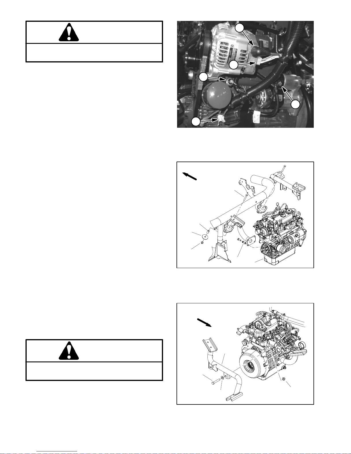
8. Disconnect wire harness connectors from engine
components:
NOTE: Beforedisconnectingwireharnessconnectors,
label all electrical leads for assembly purposes.
A. Negative battery cable and wire harness ground
from lower engine mount fastener (Fig. 11).
1
1. Throttle cable
2. Speed control lever
1
Figure 10
3. Cable jam nut
4. Throttle cable swivel
3
2
4
2
Diesel
Engine
B. Fuel stop solenoid (Fig. 12).
C. Glow plug bus (Fig. 12).
D. Temperature sender (Fig. 12).
E. Alternator connector and stud (Fig. 13).
F. Starter motor solenoid and fusible link harness
(Fig. 13).
G. Oil pressure switch (near oil filter) (Fig. 13).
CAUTION
Support the hydraulic pump assembly when removing its supporting fasteners to prevent it
from falling and causing damage or personal injury.
9. Support hydraulic pump assembly to prevent it from
moving during engine removal.
10.Removetwo(2)capscrewsandflat washersthatse-
cure hydraulic pump assembly to bell housing on engine.
1. Engine mount
2. Negative cable
1
1. Fuel return hose
2. Throttle cable swivel
3. Fuel stop solenoid
Figure 11
3. Wire harness ground
4
Figure 12
4. Glow plug bus
5. Temperature sender
5
3
2
Greensmaster 3400 Page 4 -- 15 Diesel Engine
Page 50
CAUTION
When removing engine assembly, make sure lift
or hoist can safely support 190 lbs (86 kg).
11.Attach a suitable lift or hoist to engine. Support engine with lift or hoist to prevent engine from shifting or
moving.
1
2
5
12.Remove fasteners that secure engine to machine:
A. Remove cap screw, spacer, snubbing washer
and flange nut that secure engine support to engine
mount (Fig. 14).
B. Remove two (2) cap screws, washers and lock
nuts that secure rear engine plate to rear engine
mount (Fig. 15).
IMPORTANT: Make sure to not damage the engine,
fuel hoses, hydraulic lines, electrical harness or
other parts while removing the engine. Also, make
sure that hydraulic pump assembly does not shift
location during engine removal.
13.Slowly move the engine assembly away from the hy-
draulic pump assembly to allow the pump coupling to
slide out of the engine coupling flange (Fig. 16). Once
the engine has cleared the pump coupling, carefully remove the engine from the machine.
14.If necessary, remove engine support (item 23) from
engine.
Engine Installation (Fig. 9)
4
1. Alternator stud
2. Alternator connector
3. Starter motor solenoid
FRONT
4
5
6
3
Figure 13
4. Fusible link harness
5. Oil pressure switch
2
1
3
1. Make sure that all removed engine components are
correctly installed to the engine.
2. If engine support (item 23) was removed from en-
gine, secure supportto enginewith removedfasteners.
3. Makesurethathydraulicpump assemblyiswellsup-
ported to prevent it from moving during engine Installation.
CAUTION
When installing engine assembly, make sure lift
or hoist can safely support 190 lbs (86 kg).
4. Attach a suitable lift or hoist to engine.
1. Engine
2. Engine support
3. Cap screw
FRONT
1
2
3
1. Rear engine mount
2. Cap screw (2 used)
Figure 14
4. Spacer
5. Rebound washer
6. Flange nut
4
Figure 15
3. Washer (2 used)
4. Lock nut (2 used)
Greensmaster 3400Page 4 -- 16Diesel Engine
Page 51

IMPORTANT: Make sure to not damage the engine,
fuel hoses, hydraulic lines, electrical harness or
other parts while installing the engine. Also, make
sure that hydraulic pump assembly does not shift
location during engine installation.
5. Slowly move the engine assembly toward the hydraulic pump assembly to allow the pump coupling to
slide into the engine coupling flange (Fig. 16).
13.Insert fuel supply hose and fuel return hose through
grommetsinenginesupportonfrontofengine.Remove
plugs placed during engine removal from hoses. Connectfuelsupplyhosetotheinjectorpumpfittingandfuel
return hose to the #3 injector fitting. Secure fuel hoses
with hose clamps.
14.Open fuelshutoffvalve on fueltank. Check tankand
hoses for leaks.
6. Secure hydraulic pump assembly to bell housing on
engine with two (2) cap screws and flat washers (Fig.
16).
7. Secure engine to machine:
A. Secureenginesupport(item23)toenginemount
withcapscrew,spacer,snubbing washerandflange
nut (Fig. 14).
B. Secure engine rear plate to rear engine mount
withtwo (2) cap screws, washers and lock nuts(Fig.
15).
8. Connect all electrical harness connectors to engine
using labels placed during engine removal.
9. Connectthrottle cable to the swivelon injector pump
speed control lever (Fig. 10). Adjust cable (see Adjust
ThrottleControl in the Adjustmentssection of thischapter).
10.Installexhaustsystemtomachine(seeExhaustSys-
tem Installation in this section).
11.Install radiator to machine (see Radiator Installation
in this section).
12.Install air cleaner tomachine(seeAirCleaner Instal-
lationinthis section).Makesurethatallhoseclampsare
properly tightened.
15.Fill cooling system with coolant. Check radiator and
hoses for leaks.
16.Make sure thatalternator belt tension isproperly adjusted.
17.Bleed fuel system.
18.Make sure that engine oil level is correct.
Loctite #242
27 to 33 ft--lb
1
2
3
4
(37to44N--m)
9
6
5
8
7
FRONT
Figure 16
1. Piston pump
2. Cap screw (2 used)
3. Flat washer (2 used)
4. Coupling
5. Cap screw
6. Spacer
7. Engine coupling flange
8. Bell housing
9. Key
Diesel
Engine
Greensmaster 3400 Page 4 -- 17 Diesel Engine
Page 52

Engine Bell Housing
3
1. Engine
2. Flange head screw (5 used)
Removal (Fig. 17)
6
4
1
5
2
FRONT
RIGHT
Figure 17
3. Bell housing
4. Coupling flange
5. Flange head screw (5 used)
6. Dowel pin (2 used)
Installation (Fig. 17)
NOTE: The hydraulic pump assembly needs to be re-
moved from engine before bell housing and coupling
flange can be removed.
1. Ifengineisinmachine,supportenginefrombelowto
preventitfrom shifting. Removehydraulicpumpassembly(see Piston (Traction)PumpRemoval in theService
and Repairs section of Chapter 4 -- Hydraulic System).
2. As necessary, remove bell housing and coupling
flange from engine using Figure 17 as a guide.
1. If coupling flange was removed from engine flywheel, position flange to flywheel and align mounting
holes.Secureflange toflywheelwithfive(5) flangehead
screws. Tighten screws in a star pattern.
2. Ifbell housing was removedfromengine,make sure
that spring pin is secure in upper hole of bell housing.
Position bell housing to flywheel plate and secure with
five(5)flangeheadscrews. Tightenscrewsinastar pattern.
3. If engine is in machine, install hydraulic pump assembly (see Piston (Traction) Pump Installation in the
Service and Repairs section of Chapter 5 -- Hydraulic
System).
Greensmaster 3400Page 4 -- 18Diesel Engine
Page 53

Table of Contents
Chapter 5
Hydraulic System
SPECIFICATIONS 3.............................
GENERAL INFORMATION 4.....................
Operator’s Manuals 4.........................
Check Hydraulic Fluid Level 4..................
Pushing Traction Unit 4........................
Relieving Hydraulic System Pressure 5..........
Traction Circuit Component Failure 5............
Hydraulic Hoses 6............................
Hydraulic Hose and Tube Installation (O--Ring
Face Seal Fitting) 7..........................
Hydraulic Fitting Installation (SAE Straight Thread
O--Ring Fitting into Component Port) 8.........
HYDRAULIC SCHEMATIC 10....................
HYDRAULIC FLOW DIAGRAMS 12...............
Traction Circuit 12.............................
Lower Cutting Units 14.........................
Raise Cutting Units 16.........................
Mow and Backlap 18..........................
Right and Left Turn 20.........................
SPECIAL TOOLS 22............................
TROUBLESHOOTING 26........................
General Hydraulic System Problems 26..........
Traction Circuit Problems 27....................
Mow Circuit Problems 28.......................
Lift/Lower Circuit Problems 29..................
Steering Circuit Problems 30...................
TESTING 32...................................
Charge Relief Valve Pressure Test 34............
Piston (Traction) Pump Flow Test 36.............
Wheel Motor Efficiency Test 38.................
Steering/Lift Relief Valve Pressure Test 40........
Lower Cutting Units Relief Valve (RV)
Pressure Test 42............................
Steering/Lift Circuit Gear Pump Flow Test 44.....
Power Steering Valve Test 46...................
Mow Circuit Gear Pump Flow Test 48............
Mow Circuit Relief Pressure Test 50.............
Reel Motor Case Drain Flow Test 52.............
ADJUSTMENTS 54.............................
Adjust Manifold Relief Valves 54................
Adjust Traction Control Assembly 55.............
SERVICE AND REPAIRS 56.....................
General Precautions for Removing and
Installing Hydraulic System Components 56....
Flush Hydraulic System 57.....................
Filtering Closed--Loop Traction Circuit 58.........
Hydraulic System Start--up 59..................
Gear Pump 60................................
Gear Pump Service 62.........................
Piston (Traction) Pump Neutral System 64.......
Piston (Traction) Pump 66......................
Piston (Traction) Pump Service 70..............
Piston Pump Crush Ring Replacement 72
Wheel Motors 74........................
Front
Rear Wheel Motor (Optional 3WD) 76...........
Wheel Motor Service 78.......................
Cutting Reel Motors 80........................
Cutting Reel Motor Service 82..................
Mow Control Manifold 86.......................
Mow Control Manifold Service 88...............
Control Manifold Cartridge Valve Service 91......
Lift Cylinders 92..............................
Lift Cylinder Service 94........................
Lift Control Manifold 96........................
Lift Control Manifold Service 98.................
Power Steering Valve 100......................
Power Steering Valve Service 102...............
Steering Cylinder 104..........................
Steering Cylinder Service 106..................
Hydraulic Reservoir (Machines Equipped with
Turf Guardiant Leak Detector System) 108....
Hydraulic Reservoir (Machines Not Equipped with
Turf Guardiant Leak Detector System) 110....
Leak Detector Tank (Machines Equipped with Turf
Guardiant Leak Detector System) 112........
Leak Detector Solenoid Valve Assembly (Machines
Equipped with Turf Guardiant Leak Detector
System) 116................................
EATON, MEDIUM DUTY PISTON PUMP, REPAIR
INFORMATION, MODEL 70160 VARIABLE
DISPLACEMENT PISTON PUMP
PARKER TORQMOTOR
(TC, TB, TE, TJ, TF, TG, TH AND TL SERIES)
SAUER/DANFOSS STEERING UNIT TYPE OSPM
SERVICE MANUAL
TM
SERVICE PROCEDURE
........
System
Hydraulic
Greensmaster 3300/3400 Hydraulic SystemPage 5 -- 1
Page 54

This page is intentionally blank.
Greensmaster 3300/3400Hydraulic System Page 5 -- 2
Page 55

Specifications
Item Description
Piston (Traction) Pump Variabledisplacement piston pump (Eaton model 70160)
Maximum Pump Displacement (per revolution) 1.44 in
Gear Pump 2 section, positive displacement gear pump (Casappa)
Front Section Displacement (per revolution) 0.58 in
Rear Section Displacement (per revolution) 0.33 in
Charge Circuit Relief Pressure 110to 150 PSI (7.6 to 10.3 bar)
Traction Circuit Relief Pressure
Forward 3000 PSI (207 bar)
Reverse 3000PSI (207 bar)
Front Wheel Motors Orbital rotor motor (Parker TF Series)
Displacement (per revolution) 10.3 in
Rear Wheel Motor (Optional 3WD Kit) Orbital rotor motor (Parker TG Series)
Displacement (per revolution) 20.6 in
Mow Circuit Relief Pressure 2700 to 3300 PSI (186 to 227 bar)
Cutting Reel Motor Gear motor (Casappa)
Maximum Pump Displacement (per revolution) 0.73 in
Power Steering Valve Hydrostatic Steering Unit (Sauer--Danfoss Type OSPMS)
Displacement (per revolution) 4.5 in
3
(23.6 cc)
3
(9.5 cc)
3
(5.4 cc)
3
(169 cc)
3
(337 cc)
3
(12 cc)
3
(74 cc)
Steering/Lift Circuit Relief Pressure 1160PSI (80 bar)
Hydraulic Filter Spin--on cartridge type
Hydraulic Oil See Operator’s Manual
Hydraulic Reservoir Capacity
Machines with Turf Defender
Machines without Turf Defender
TM
Leak Detector 6.8 gal. U.S. (25.7 L)
TM
Leak Detector 5.5gal. U.S. (20.8 L)
System
Hydraulic
Greensmaster 3300/3400 Hydraulic SystemPage 5 -- 3
Page 56

General Information
Operator’s Manuals
The Traction Unit and Cutting Unit Operator’s Manuals
provide information regarding the operation, general
maintenanceproceduresandmaintenanceintervalsfor
your Greensmaster machine. Refer to these publications for additional information when servicing the machine.
Check Hydraulic Fluid Level
Thehydraulicsystemon yourGreensmastermachineis
designed to operate on high quality hydraulic fluid.
Check level of hydraulic fluid daily. Refer to Traction
Unit Operator’s Manual for fluid level checking procedure and hydraulic oil recommendations.
1
2
Pushing Traction Unit
In case of emergency, your Greensmaster can be
pushed for a very short distance. However, Toro does
not recommend this as a standard procedure.
1. Make sure that engine is not running.
2. Locateby--pass valve on piston(traction)pump(Fig.
2). Rotate by--pass valve so slot is vertical.
IMPORTANT: Do not push the machine faster than
2mph(3.2kph) because the traction system may be
damaged.Ifmachinemust be movedaconsiderable
distance (more than a few feet), transport it on a
truck or trailer.
3. Slowly push machine.
4. Before starting engine, rotate piston (traction) pump
by--pass valve so slot is horizontal. Do not start engine
when by--pass valve is in the vertical position.
Figure 1
1. Hydraulic reservoir 2. Fuel tank
1
2
Figure 2
1. Piston (traction) pump 2. By--pass valve
Greensmaster 3300/3400Hydraulic System Page 5 -- 4
Page 57

Relieving Hydraulic System Pressure
Before disconnecting or performing any work on your
Greensmaster hydraulic system, all pressure in the hydraulic system must be relieved.
To relievehydraulic pressure in the traction circuit, park
machineona levelsurfacewiththecutting unitslowered
and off. Turnignition switch to OFF and allow engine to
stop. If machine is parked on an incline or slope, pressure in the traction circuit WILL NOT be relieved.
To relieve hydraulicpressure in liftcircuit, fully lower the
cutting units to the ground. Turn ignition switch to OFF
and allow engine to stop.Make surethat after lowering,
none of the cutting units are not being supported by the
lift cylinders.
Traction Circuit Component Failure
The traction circuit on your Greensmaster machine is a
closed loop system that includes the piston (traction)
pumpand two (2)wheel motors (three(3) wheel motors
are included if machine is equipped with optional 3WD
kit). If a component in the traction circuit should fail, debris and contamination from the failed component will
circulatethroughoutthetractioncircuit.Thiscontamination can damage other components in the circuit so it
must be removed to prevent additional component failure.
The recommended method of removing traction circuit
contamination would be to temporarily install the Toro
high flow hydraulic filter (see Special Tools in thischapter) into the circuit. This filtershould beused when connecting hydraulic test gauges in order to test traction
circuitcomponentsorafter replacing afailedtractioncircuit component (e.g. piston (traction) pump or wheel
motor). The filter will ensure that contaminates are removedfromtheclosedloopandthus,donotcauseadditional component damage.
To relieve hydraulic pressure in the steeringcircuit,park
machineona levelsurfacewiththecutting unitslowered
and off. Turn ignition switch to OFF. After engine has
come to a complete stop, rotate steering wheel in both
directions.
Hydraulic pressure in the mow circuit is relieved when
the ignition switch is turned to OFF.
Once the Toro high flow hydraulic filter kit has been
placedin the circuit,raise and support themachine with
all drive wheels off the ground. Then, operate the tractioncircuit to allow oilflow throughout thecircuit. The filter will remove contamination from the traction circuit
duringoperation. Because the Toro high flow filter is bi-directional, the traction circuit can be operated in both
the forward and reverse direction. The filter should be
removed from the machine after contamination has
been removed from the traction circuit. See Filtering
Closed--LoopTractionCircuitintheServiceandRepairs
section of this chapter for additional information on using the Toro high flow hydraulic filter.
Thealternativetousing the Torohighflowhydraulic filter
kit after a traction circuit component failure would be to
disassemble, drain and thoroughly clean all components, tubes and hoses in the traction circuit. If any debris remains in the traction circuit and the machine is
operated,thedebris cancauseadditionalcircuitcomponent failure.
System
Hydraulic
Greensmaster 3300/3400 Hydraulic SystemPage 5 -- 5
Page 58

Hydraulic Hoses
Hydraulichoses are subjecttoextreme conditions such
aspressuredifferentialsduring operation and exposure
to weather, sun, chemicals, very warm storage conditionsormishandlingduring operation andmaintenance.
These conditions can cause hose damage and deterioration. Some hoses are more susceptible to these
conditions than others. Inspect all machine hydraulic
hoses frequently for signs of deterioration or damage:
WARNING
Beforedisconnecting or performing any work on
hydraulic system, relieve all pressure in system
(seeRelieving Hydraulic System Pressure in this
section).
Hard, cracked, cut, abraded, charred, leaking or
otherwise damaged hose.
Kinked, crushed, flattened or twisted hose.
Blistered, soft, degraded or loose hose cover.
Cracked, damaged or badly corroded hose fittings.
When replacing a hydraulic hose, be sure that the hose
is straight (not twisted) before tightening the fittings.
This can be done by observing the imprint (layline) on
thehose.Usetwowrenches; hold the hose straightwith
one wrench and tighten the hose swivel nut onto the fitting with the other wrench (see Hydraulic Hose and
Tube Installation in this section). If the hose has an elbowatoneend,tightenthe swivel nut onthatendbefore
tightening the nut on the straight end of the hose.
For additional hydraulic hose information, refer to Toro
Service Training Book, Hydraulic Hose Servicing (Part
Number 94813SL).
Keepbodyandhandsawayfrompinholeleaksor
nozzles that eject hydraulic fluid under high
pressure. Use paper or cardboard, not hands, to
search for leaks. Hydraulic fluid escaping under
pressure can have sufficient force to penetrate
the skin and cause serious injury. If fluid is injected into the skin, it must be surgically removed within a few hours by a doctor familiar
withthistypeofinjury.Gangrenemay result from
such an injury.
Greensmaster 3300/3400Hydraulic System Page 5 -- 6
Page 59

Hydraulic Hose and Tube Installation (O--Ring Face Seal Fitting)
1. Makesurethreads and sealing surfaces of the hose/
tube and the fitting are free of burrs, nicks, scratchesor
any foreign material.
2. Asapreventative measure against leakage, it is recommended that the face seal O--ring be replaced any
time the connection is opened. Make sure the O--ringis
installedandproperlyseatedinthefittinggroove.Lightly
lubricate the O--ring with clean hydraulic oil.
3. Place the hose/tube against the fitting body so that
theflatface ofthehose/tubesleevefullycontacts theO-ring in the fitting.
4. Thread the swivel nut onto the fitting by hand. While
holding the hose/tube with a wrench, use a torque
wrench to tighten the swivel nut to the recommended
installation torque shown in Figure 5. This tightening
process will require the use of an offset wrench (e.g.
crowfoot wrench). Use of an offset wrench will affect
torque wrench calibration due to the effective length
change of the torque wrench. Tightening torque when
usingatorquewrenchwithanoffsetwrenchwillbelower
than the listed installation torque (see Using a Torque
Wrench with an Offset Wrench in the TorqueSpecificationssection of C hapter 2 --Product Records and Maintenance).
C. Useasecondwrenchtotightenthenuttothecorrect Flats From Wrench Resistance (F.F.W.R.).The
markingsonthenutandfittingbodywillverifythat the
connection has been properly tightened.
Fitting Size F.F.W.R.
4 (1/4 in. nominal hose or tubing) 1/2 to 3/4
6 (3/8 in.) 1/2 to 3/4
8 (1/2 in.) 1/2 to 3/4
10 (5/8 in.) 1/2 to 3/4
12 (3/4 in.) 1/3 to 1/2
16 (1 in.) 1/3 to 1/2
Swivel Nut
Tube or Hose
O--ring
Fitting Body
Figure 3
5. If a torque wrench is not available or if space at the
swivelnutpreventsuseofatorquewrench,analternate
method of assembly is the Flats From Wrench Resist-
Mark Nut
and Fitting
Body
Final
Position
ance (F.F.W.R.) method (Fig. 2).
A. Usingawrench,tighten the swivel nutontothefittinguntillightwrench resistanceisreached(approximately 30 in--lb).
B. Mark the swivel nut and fitting body. Hold the
hose/tube with a wrench to prevent it from turning.
AT WRENCH RESISTANCE
Extend Line
Figure 4
Fitting Dash Size Hose/Tube Side Thread Size Installation Torque
4 9/16 -- 18 18to22ft--lb(25to29N--m)
6 11/16 - - 16 27to33ft--lb(37to44N--m)
8 13/16 -- 16 37to47ft--lb(51to63N--m)
10 1--14 60 to 74 ft--lb (82 to 100 N--m)
12 13/16--12 85 to 105 ft--lb (116 to 142 N--m)
16 17/16--12 110 to 136 ft--lb (150 to 184 N--m)
Initial
Position
AFTER TIGHTENING
System
Hydraulic
20 1 11/16 -- 12 140 to 172 ft--lb (190 to 233 N--m)
Greensmaster 3300/3400 Hydraulic SystemPage 5 -- 7
Figure 5
Page 60

Hydraulic Fitting Installation (SAE Straight Thread O--Ring Fitting into Component Port)
Non--Adjustable Fitting (Fig. 6)
1. Make sure all threads and sealing surfaces of fitting
and component port are free of burrs, nicks, scratches
or any foreign material.
2. Asapreventative measure against leakage, it is recommended that the O--ring be replaced any time the
connection is opened.
3. Lightly lubricate the O--ring with clean hydraulic oil.
Fittingthreadsshould becleanwithnolubricantapplied.
IMPORTANT: Before installing fitting into port, determine port material. If fitting is to be installed into
an aluminum port, installation torque is reduced.
4. Install the fitting into the port. Then, use a torque
wrench and socket to tighten the fitting to the recommended installation torque shown in Figure 7.
NOTE: Useof an offset wrench (e.g. crowfoot wrench)
will affect torque wrench c alibration due to the effective
length change of the torque wrench. Tightening torque
when using a torque wrench with an offset wrench will
be less than the recommended installation torque. See
Using a Torque Wrench with an Offset Wrench in the
Torque Specifications section of Chapter 2 -- Product
RecordsandMaintenancetodetermine necessary conversion information.
5. If a torque wrench is not available, or if space at the
portpreventsuseof atorquewrench,analternatemethod of assembly is the Flats From Finger Tight (F.F.F.T.)
method.
A. Install the fitting into the port and tighten it down
full length until finger tight.
B. If port material is steel, tighten the fitting to the
listed F.F.F.T. If port material is aluminum, tighten fitting to 60% of listed F.F.F.T.
Fitting Size F.F.F.T.
4 (1/4 in. nominal hose or tubing) 1.00 +
6(3/8in.) 1.50+
8(1/2in.) 1.50+
10 (5/8 in.) 1.50 +
12 (3/4 in.) 1.50 +
16 (1 in.) 1.50 +
Fitting
O--ring
0.25
0.25
0.25
0.25
0.25
0.25
Figure 6
Fitting
Dash Size
Fitting Port Side
Thread Size
Installation Torque Into
Steel Port
Installation Torque Into
Aluminum Port
4 7/16 -- 20 15to19ft--lb(21to25N--m) 9to11ft--lb(13to15N--m)
5 1/2 -- 20 18to22ft--lb(25to29N--m) 11to15ft--lb(15to20N--m)
6 9/16 -- 18 34to42ft--lb(47to56N--m) 20to26ft--lb(28to35N--m)
8 3/4 -- 16 58to72ft--lb(79to97N--m) 35to43ft--lb(48to58N--m)
10 7/8 -- 14 99 to 121 ft--lb (135 to 164 N--m) 60 to 74 ft--lb (82 to 100 N--m)
12 11/16--12 134 to 164 ft--lb (182 to 222 N--m) 81 to 99 ft--lb (110 to 134 N--m)
14 13/16--12 160 to 196 ft--lb (217 to 265 N--m) 96 to 118 ft--lb (131 to 160 N--m)
16 15/16--12 202 to 248 ft--lb (274 to 336 N--m) 121 to 149 ft--lb (165 to 202 N--m)
20 15/8--12 247 to 303 ft--lb (335 to 410 N--m) 149 to 183 ft--lb (202 to 248 N--m)
Figure 7
Greensmaster 3300/3400Hydraulic System Page 5 -- 8
Page 61

Adjustable Fitting (Fig. 8)
1. Make sure all threads and sealing surfaces of fitting
and component port are free of burrs, nicks, scratches
or any foreign material.
2. Asapreventative measure against leakage, it is recommended that the O--ring be replaced any time the
connection is opened.
3. Lightly lubricate the O--ring with clean hydraulic oil.
Fittingthreadsshould becleanwithnolubricantapplied.
4. Turnback the lock nut as far as possible. Make sure
the back up washer is not loose and is pushed up as far
as possible (Step 1 in Figure 9).
IMPORTANT: Before installing fitting into port, determine port material. If fitting is to be installed into
an aluminum port, installation torque is reduced.
Lock Nut
Back--up Washer
O--ring
Figure 8
5. Install the fitting into the port and tighten finger tight
until the washer contacts the face of the port (Step 2).
6. To put the fittinginthedesiredposition,unscrewitby
the required amount, but no more than one full turn
(Step 3).
7. Hold the fitting in the desired position with a wrench
and use a torque wrench to tighten the fittingto the recommended installation torque shown in Figure 7. This
tightening process will require the use of an offset
wrench (e.g. crowfootwrench). Use of an offsetwrench
will affect torque wrench c alibration due to the effective
length change of the torque wrench. Tightening torque
when using a torque wrench with an offset wrench will
be lower than the listed installation torque (see Using a
Torque Wrench with an Offset Wrench in the Torque
Specifications section of Chapter 2 -- Product Records
and Maintenance).
8. If a torque wrench is not available, or if space at the
portpreventsuseof atorquewrench,analternatemethod of assembly is the Flats From Finger Tight (F.F.F.T.)
method. Hold the fitting in the desired position with a
wrench and, if port material is steel, tighten the lock nut
withasecondwrenchtothe listed F.F.F.T(Step4).Ifport
material is aluminum, tighten fitting to 60% of listed
F.F.F.T.
Step 3Step 1
Step 2 Step 4
Figure 9
System
Hydraulic
Fitting Size F.F.F.T.
4 (1/4 in. nominal hose or tubing) 1.00 +
6(3/8in.) 1.50+
8(1/2in.) 1.50+
10 (5/8 in.) 1.50 +
12 (3/4 in.) 1.50 +
16 (1 in.) 1.50 +
Greensmaster 3300/3400 Hydraulic SystemPage 5 -- 9
0.25
0.25
0.25
0.25
0.25
0.25
Page 62

Hydraulic Schematic
PORT
BACK
FORWARD
TOP
PORT
3000
GEAR
70 to
PSI
G2
PUMP
PORT
FRONT
PSI
100
PSI
110 -- 150
JOINT END
PORT BALL
LR
STEERING CYLINDER
RIGHT FRONT (#3)
(Extend to Lower)
CENTER (#1)
(Extend to Raise)
4.5
OR3
.028
C6C1C4
OR2
.028
1160
POWER
S4
S3
PSI
VALVE
STEERING
C5
S2
TE
P
C2
C3
OR1
.037
400
PSI
RV
S1
25
PSI
PT
G1
A
HYDROSTAT
C
4.0 GPM
AB
10.3
AB
10.3
ENGINE
1.9 GPM
1.44
.58
.33
MOTOR
RIGHT
MOTOR
LEFT
20.6
BA
B
G1
BOTTOM
C1
PSI
3000
MOW = 6.7 GPM AT3.8 MPH
PORT
BYPASS
OPTIONAL 3WD
VALVE
TRANSPORT = 17.5 GPM AT10 MPH
LEFT FRONT (#2)
RIGHT FRONT
MV
7.0 GPM
PORV
COOLER
OPTIONAL OIL
OR1
OR2
FC
MOW
CONTROL
MANIFOLD
LC
PRV
IN
OUT
T
P
G
SUCTION
STRAINER
S1
BREATHER
LIFT
CONTROL
MANIFOLD
(ExtendtoLower)
REEL (#3)
.73
FRONT
PORT
CENTER REEL
FRONT
PORT
(#1)
.73
.73
FRONT
REEL (#2)
LEFT FRONT
M2
PORT
M1
SW
NOTE: A larger hydraulic schematic is
included in Chapter 9 -- Foldout Drawings
LEAK DETECTOR KIT
LEAK
DETECTOR
VOLUME
TANK
EXPANSION
Greensmaster 3300/3400Hydraulic System Page 5 -- 10
Page 63

This page is intentionally blank.
System
Hydraulic
Greensmaster 3300/3400 Hydraulic SystemPage 5 -- 11
Page 64

Hydraulic Flow Diagrams
PORT
BACK
FORWARD
TOP
3000
PORT
70 to
PSI
GEAR
G2
PUMP
PORT
FRONT
PSI
100
PSI
110 -- 150
JOINT END
PORT BALL
LR
STEERING CYLINDER
RIGHT FRONT (#3)
(Extend to Lower)
CENTER (#1)
(Extend to Raise)
4.5
OR3
.028
C6C1C4
OR2
.028
1160
POWER
S4
S3
PSI
VALVE
STEERING
C5
S2
TE
P
C2
C3
OR1
.037
400
PSI
RV
S1
25
PSI
PT
G1
A
HYDROSTAT
C
4.0 GPM
AB
10.3
AB
10.3
ENGINE
1.9 GPM
1.44
.58
.33
MOTOR
RIGHT
MOTOR
LEFT
20.6
BA
B
G1
PSI
3000
OPTIONAL 3WD
PORT
BOTTOM
VALVE
C1
BYPASS
MOW = 6.7 GPM AT3.8 MPH
TRANSPORT = 17.5 GPM AT10 MPH
All solenoids are shown
as de--energized.
Traction Circuit (Forward Direction Shown)
Greensmaster 3300/3400
LEFT FRONT(#2)
Traction pedal is pressed for
the forward direction.
(Extend to Lower)
REEL (#3)
RIGHT FRONT
High Pressure
Low Pressure (Charge)
Return or Suction
.73
Flow
FRONT
PORT
CENTER REEL
FRONT
PORT
(#1)
.73
.73
LEFT FRONT
REEL (#2)
FRONT
PORT
LIFT
CONTROL
MANIFOLD
SW
M2
M1
MV
7.0 GPM
PORV
COOLER
OPTIONAL OIL
LEAK DETECTOR KIT
OR1
OR2
FC
LEAK
DETECTOR
MOW
CONTROL
MANIFOLD
LC
PRV
IN
OUT
VOLUME
T
P
G
SUCTION
STRAINER
S1
BREATHER
TANK
EXPANSION
Greensmaster 3300/3400Hydraulic System Page 5 -- 12
Page 65

Traction Circuit
The traction circuit piston pump is a variable displacement pump that is directly coupled to the engine. Pushingthetractionpedalcontrolsthevariabledisplacement
piston pump swash plate to create a flow of oil. This oil
is directed to the wheel motors. Operating pressure on
the high pressure side of the closed traction circuit loop
is determined by the amount of load developed at the
fixed displacement wheel motors. As the load increases,circuitpressurecanincreasetoreliefvalvesettings: 3000 PSI (207 bar) in both forward and reverse.
If pressure exceeds the relief setting, oil flows through
the relief valve to the low pressure side of the closed
loop traction circuit.
The traction circuit pump and wheel motors use a small
amount of hydraulic fluid for internal lubrication. Fluid is
designed to leak across traction pump and motor components into the case drain. This leakage results in the
lossofhydraulic fluidfromtheclosedloop tractioncircuit
thatmust be replaced.The charge circuit is designedto
replace this traction circuit leakage.
The gear pump section that supplies oil to the steering
andliftcircuitsalso provides charge circuit oil.Thisgear
pump is driven directly off the piston (traction) pump. It
provides a constant supply of charge oil to the traction
circuit to make up for oil that is lost due to internal leakage in the traction pump and wheel motors.
Charge pump flow is directed to the low pressure side
of the closed loop traction circuit. Charge circuit pressure (110 to 150 PSI / 7.6 to 10.3 bar) is maintained by
the charge relief valve that is attached to the piston
pump back plate.
The functional control lever on TriFlex Greensmaster
machines has positions for neutral, mow and transport.
When the functional control lever is in the neutral position,thetraction pedal is secured intheneutralposition.
The mow position allows traction pedal inputs that are
appropriateformowspeedsby limitingthemovementof
the piston pump swash plate. The transport position allows full movement of the traction pedal so complete
pump swash rotation is possible.
Forward
The piston (traction) pump is driven directly by the engine. The hydraulic traction circuit acts essentially as a
closed loop. Taking its suction directly from the return
sideofthewheelmotorsofthetractioncircuit,thepiston
pump supplies oil flow to the wheel motors through the
supply side of the traction circuit.
Withtheenginerunningandtractionpedalintheneutral
position, the piston pump supplies no flow to the wheel
motors. When the traction pedal is pressed to the forward position, the linkage from the pedal positions the
swash plate in the piston pump so oil flows out the top
port of the pump. Oil flow out of the top port goes to the
wheel motors and turns them in the forward direction.
Oilflowingout of the wheelmotorsreturns to the bottom
portof the piston pump and is continuously pumpedout
the top port.
Reverse
The traction circuit operates essentially the same in reverse as it does in the forward direction. However, the
flow through the circuit is reversed.
Withtheenginerunningandtractionpedalintheneutral
position, the piston pump supplies no flow to the wheel
motors. When the traction pedal is pressed to the reverse position, the linkage from the pedal positions the
swash plate in the piston pump so oil flows out the bottomportofthepump. Oilflowoutofthebottomportgoes
tothewheel motors and turnstheminthe reverse direction.
Oilflowingoutofthewheel motors returns to thetopport
of the piston pump and is continuously pumped out the
bottom port.
Traction Circuit Cooling
Thepiston pump includesa shuttle valvethat bleeds off
asmallamountofhydraulicfluidforcoolingof theclosed
looptraction circuit. Thisvalve allows asmall amount of
hydraulic oil to pass from the low pressure side of the
traction circuit while operating the traction unit in either
direction. A relief valve in the piston pump back plate
prevents shuttle valve bleed off until the relief valve
opens(70to 100 PSI / 4.9to6.8 bar). The chargecircuit
replenishesoilthatisbledfromthetractioncircuitbythe
shuttle valve.
NOTE: Theshuttlevalveassemblyislocatedin the piston pump back plate. Access to the shuttle valve requires removal of the back plate from the piston pump.
System
Hydraulic
Greensmaster 3300/3400 Hydraulic SystemPage 5 -- 13
Page 66

PORT
BACK
FORWARD
TOP
PORT
3000
GEAR
70 to
PSI
G2
PUMP
PORT
FRONT
PSI
100
PSI
110 -- 150
JOINT END
PORT BALL
LR
STEERING CYLINDER
RIGHT FRONT (#3)
(Extend to Lower)
CENTER (#1)
(Extend to Raise)
4.5
OR3
.028
C6C1C4
OR2
.028
1160
POWER
S4
S3
PSI
VALVE
STEERING
C5
S2
TE
P
C2
C3
OR1
.037
400
PSI
RV
S1
25
PSI
PT
G1
A
HYDROSTAT
C
4.0 GPM
AB
10.3
AB
10.3
ENGINE
1.9 GPM
1.44
.58
.33
MOTOR
RIGHT
MOTOR
LEFT
20.6
BA
B
G1
BOTTOM
C1
PSI
3000
MOW = 6.7 GPM AT3.8 MPH
PORT
BYPASS
OPTIONAL 3WD
VALVE
TRANSPORT = 17.5 GPM AT10 MPH
(Extend to Lower)
LEFT FRONT (#2)
Solenoids S1, S2, S3 and S4 in
lift control manifold are shown in
Lower Cutting Units
Greensmaster 3300/3400
High Pressure
energized position.
.73
REEL (#3)
RIGHT FRONT
Low Pressure (Charge)
Return or Suction
Flow
FRONT
PORT
CENTER REEL
FRONT
PORT
(#1)
.73
.73
LEFT FRONT
REEL (#2)
FRONT
PORT
LIFT
CONTROL
MANIFOLD
SW
M2
M1
MV
7.0 GPM
PORV
COOLER
OPTIONAL OIL
LEAK DETECTOR KIT
OR1
OR2
FC
LEAK
DETECTOR
MOW
CONTROL
MANIFOLD
LC
PRV
IN
OUT
VOLUME
T
P
G
SUCTION
STRAINER
S1
BREATHER
TANK
EXPANSION
Greensmaster 3300/3400Hydraulic System Page 5 -- 14
Page 67

Lower Cutting Units
The tandem gear pump is directly coupled to the piston
(traction) pump. The rear gear pump section supplies
hydraulic flow for the steering circuit (priority flow), for
raisingandloweringthecuttingunits and for the traction
chargecircuit. The gearpump takes its suctionfrom the
hydraulic reservoir. Maximum circuit pressure of 1160
PSI (80 bar) is limited by the relief valve located in the
power steering valve.
The lift controlmanifold includes four (4) electrically operatedsolenoidvalves.SolenoidvalveS1causescircuit
flow to by--pass the lift cylinders when de--energized
anddirects flow tothe cylinders whenenergized. Directionalsolenoid valve S2 is used to directoil flow to raise
the cutting units when de--energized and lower them
whenenergized.Whenenergized,solenoid valve S3 allows hydraulic flow to and from the front cutting unit lift
cylinders (#2 and #3) and prevents oil passage to and
from the lift cylinders when de--energized. When energized, solenoid valve S4 allows hydraulic flow to and
fromthecentercutting unit liftcylinder(#1)andprevents
oil passage to and from the lift cylinder when de--energized.
The console arm joystick is used to raise and lower the
cutting units. The joystick acts as an input to the TEC
controller to send electrical outputs to appropriate lift
control manifold solenoid coils in order to raise or lower
the cutting units.
While operating the machine during conditions of not
raising or lowering the cutting units (joystick in the neutral (center) position), all of the lift manifold solenoid
valves(S1,S2, S3andS4)arede--energized.Flowfrom
therear gear pump section isdirected through thepowersteeringvalve,de--energizedsolenoidvalveS1inthe
lift control manifold, oil filter and to the traction charge
circuit. Flow in excess of charge circuit needs then returns to the gear pump input.
Lower Cutting Units
When the joystick is moved to the lower position, the
Toro Electronic Controller (TEC) energizes all of the lift
controlmanifoldsolenoidvalvesforapproximatelythree
(3) seconds. This time frame ensures that the cutting
unitswillbefully loweredtoallowthemtofloat duringoperation.Thecontroller also provides ashortdelay in energizing solenoid valve S4 which delays the lowering of
the center cutting unit (#1).
Energizedliftmanifold solenoidsS1andS2directcircuit
flow toward the lift cylinders in the correct direction to
lower the cutting units. The front lift cylinders extend to
lower the cutting units while the center lift cylinder retracts to lower the cutting unit. Hydraulic pressure
againstthe lift cylinder pistons moves their shafts causingthecutting unitstolower.Atthesametime,theliftcylinderpistonspushthehydraulicfluidoutofthecylinders
toenergized solenoid valvesS3 (front liftcylinders) and
S4 (center lift cylinder). Return flow continues through
energized solenoid valve S2, to the oil filter and then to
the traction charge circuit.
Lowering speed for each of the front cutting units (#2
and #3) is controlled by a 0.028 orifice (OR2 and OR3)
intheliftcontrolmanifold. A 0.037 orifice (OR1) controls
lowering speed for the center cutting unit (#1).
If the lift cylinders should reach the end of their stroke
whiletheliftmanifoldsolenoidsarestillenergized,liftcircuit pressure will increase. The lift circuit lower relief
valve (RV) in the lift control manifold allows lift circuit
pressureto be limitedto 400 PSI(27.6 bar) whilelowering the cutting units.
NOTE: Adjustment of the lift control manifold lift circuit
lower relief valve (RV) is not recommended.
When the lift control manifold solenoid valves are de-energized by the TEC controller, spring action returns
the valves to their original position stopping lift cylinder
movement. The lift cylinder position is locked in place
sincethere is no complete circuit of flow to and from the
lift cylinders. Hydraulic flow by--passes the lift cylinders
and is routed to the oil filter and charge circuit.
System
Hydraulic
Greensmaster 3300/3400 Hydraulic SystemPage 5 -- 15
Page 68

PORT
BACK
FORWARD
TOP
PORT
3000
GEAR
70 to
PSI
G2
PUMP
PORT
FRONT
PSI
100
PSI
110 -- 150
JOINT END
PORT BALL
LR
STEERING CYLINDER
RIGHT FRONT (#3)
(Extend to Lower)
CENTER (#1)
(Extend to Raise)
4.5
OR3
.028
C6C1C4
OR2
.028
1160
POWER
S4
S3
PSI
VALVE
STEERING
C5
S2
TE
P
C2
C3
OR1
.037
400
PSI
RV
S1
25
PSI
PT
G1
A
HYDROSTAT
C
4.0 GPM
AB
10.3
AB
10.3
ENGINE
1.9 GPM
1.44
.58
.33
MOTOR
RIGHT
MOTOR
LEFT
20.6
B BA
G1
BOTTOM
C1
PSI
3000
MOW = 6.7 GPM AT3.8 MPH
PORT
BYPASS
OPTIONAL 3WD
VALVE
TRANSPORT = 17.5 GPM AT10 MPH
(Extend to Lower)
LEFT FRONT (#2)
Solenoids S1, S3 and S4 in lift
control manifold are shown in
Raise Cutting Units
Greensmaster 3300/3400
High Pressure
energized position.
.73
REEL (#3)
RIGHT FRONT
Low Pressure (Charge)
Return or Suction
Flow
FRONT
PORT
CENTER REEL
FRONT
PORT
(#1)
.73
.73
FRONT
REEL (#2)
LEFT FRONT
MV
7.0 GPM
PORV
COOLER
OPTIONAL OIL
LEAK DETECTOR KIT
OR1
OR2
FC
LEAK
DETECTOR
MOW
CONTROL
MANIFOLD
LC
PRV
IN
OUT
VOLUME
T
P
G
SUCTION
STRAINER
S1
BREATHER
TANK
EXPANSION
LIFT
CONTROL
MANIFOLD
M2
PORT
M1
SW
Greensmaster 3300/3400Hydraulic System Page 5 -- 16
Page 69

Raise Cutting Units
The tandem gear pump is directly coupled to the piston
(traction) pump. The rear gear pump section supplies
hydraulic flow for the steering circuit (priority flow), for
raisingandloweringthecuttingunits and for the traction
chargecircuit. The gearpump takes its suctionfrom the
hydraulic reservoir. Maximum circuit pressure of 1160
PSI (80 bar) is limited by the relief valve located in the
power steering valve.
The lift controlmanifold includes four (4) electrically operatedsolenoidvalves.SolenoidvalveS1causescircuit
flow to by--pass the lift cylinders when de--energized
anddirects flow tothe cylinders whenenergized. Directionalsolenoid valve S2 is used to directoil flow to raise
the cutting units when de--energized and lower them
whenenergized.Whenenergized,solenoid valve S3 allows hydraulic flow to and from the front cutting unit lift
cylinders (#2 and #3) and prevents oil passage to and
from the lift cylinders when de--energized. When energized, solenoid valve S4 allows hydraulic flow to and
fromthecentercutting unit liftcylinder(#1)andprevents
oil passage to and from the lift cylinder when de--energized.
The console arm joystick is used to raise and lower the
cutting units. The joystick acts as an input to the TEC
controller to send electrical outputs to appropriate lift
control manifold solenoid coils in order to raise or lower
the cutting units.
While operating the machine during conditions of not
raising or lowering the cutting units (joystick in the neutral (center) position), all of the lift manifold solenoid
valves(S1,S2, S3andS4)arede--energized.Flowfrom
therear gear pump section isdirected through thepowersteeringvalve,de--energizedsolenoidvalveS1inthe
lift control manifold, oil filter and to the traction charge
circuit. Flow in excess of charge circuit needs then returns to the gear pump input.
Raise Cutting Units
Whenthejoystickismovedtotheraiseposition,theToro
Electronic Controller (TEC) energizes lift control manifold solenoid valves S1, S3 and S4 for approximately
three(3) seconds. Thistime frame ensures thatthe cutting units will be fully raised. The controller provides a
shortdelayinenergizingsolenoidvalveS4whichdelays
the raising of the center cutting unit (#1).
Energized lift manifold solenoids S1, S3 (front lift cylinders) and S4 (center lift cylinder) direct circuit flow towardthe lift cylindersin the correct direction to raise the
cutting units. The front lift cylinders retract to raise the
cuttingunitswhilethe center liftcylinderextendstoraise
the cutting unit.Hydraulic pressure against the lift cylinder pistons moves their shafts causing the cutting units
to raise. At the same time, the lift cylinder pistons push
the hydraulic fluid out of the cylinders to de--energized
solenoid valve S2. Return flow continues to the oil filter
and then to the traction charge circuit.
A0.037orifice(OR1) controls raising speed forthecentercuttingunit(#1). Flowtothefrontliftcylinders(cutting
units#2and#3)bypassestheliftmanifold orifices (OR2
and OR3) when the front cutting units are being raised.
When the lift control manifold solenoid valves are de-energized by the TEC controller, spring action returns
the valves to their original position stopping lift cylinder
movement. The lift cylinder position is locked in place
sincethere is no complete circuit of flow to and from the
lift cylinders. Hydraulic flow by--passes the lift cylinders
and is routed to the oil filter and charge circuit.
System
Hydraulic
Greensmaster 3300/3400 Hydraulic SystemPage 5 -- 17
Page 70

PORT
BACK
FORWARD
TOP
3000
PORT
70 to
PSI
GEAR
G2
PUMP
PORT
FRONT
PSI
100
PSI
110 -- 150
JOINT END
PORT BALL
LR
STEERING CYLINDER
RIGHT FRONT (#3)
(Extend to Lower)
CENTER (#1)
(Extend to Raise)
4.5
OR3
.028
C6C1C4
OR2
.028
1160
POWER
S4
S3
PSI
VALVE
STEERING
C5
S2
TE
P
C2
C3
OR1
.037
400
PSI
RV
S1
25
PSI
PT
G1
A
HYDROSTAT
C
4.0 GPM
AB
10.3
AB
10.3
ENGINE
1.9 GPM
1.44
.58
.33
MOTOR
RIGHT
MOTOR
LEFT
20.6
BA
B
G1
BOTTOM
C1
PSI
3000
MOW = 6.7 GPM AT3.8 MPH
PORT
BYPASS
OPTIONAL 3WD
VALVE
TRANSPORT = 17.5 GPM AT10 MPH
LEFT FRONT (#2)
(Extend to Lower)
REEL (#3)
RIGHT FRONT
.73
FRONT
PORT
CENTER REEL
FRONT
PORT
(#1)
.73
.73
LEFT FRONT
REEL (#2)
FRONT
PORT
LIFT
CONTROL
MANIFOLD
SW
M2
M1
MV
7.0 GPM
PORV
COOLER
OPTIONAL OIL
OR1
OR2
FC
MOW
CONTROL
MANIFOLD
LC
PRV
IN
OUT
T
P
G
SUCTION
STRAINER
S1
BREATHER
High Pressure
Low Pressure (Charge)
Return or Suction
Flow
Pressure Reducing Valve (PRV)
in mow control manifold is shown
Mow
Greensmaster 3300/3400
in energized position.
LEAK DETECTOR KIT
LEAK
DETECTOR
VOLUME
TANK
EXPANSION
Greensmaster 3300/3400Hydraulic System Page 5 -- 18
Page 71

Mow and Backlap
The tandem gear pump is directly coupled to the piston
(traction) pump. The front gear pump section supplies
hydraulic flow for the mow circuit. The gear pump takes
its suction from the hydraulic reservoir and supplies oil
flow to the mow control manifold and to the cutting reel
motors. Maximum circuit pressure is limited by the proportional relief valve (PRV) located in the mow control
manifold.
With the functional control lever and joystick not in the
mowposition,proportionalreliefvalve (PRV)inthemow
control manifold is de--energized. The de--energized
PRVroutesgearpump flow directly tothehydraulicreservoir by--passing the cutting reel motors. Additionally,
manifold pressure reducing valve (PORV) will remain
seatedto prevent thereel motors (and reels)from rotating.
Mow
With the engine running, the functional control lever in
MOWandthejoystickmovedtothe reels lower position,
proportional relief valve (PRV) is energized by the TEC
controller.In the energized position, this valve directs oil
flow toward the reel motors and also functions as the
mow circuit relief valve.
Oilflow from manifold portP flows through theflow control valve (FC) used to adjust reel speed. Flow across
the flow control valve is pressure compensated by the
logic cartridge valve (LC). The logic cartridge valve
maintains a pressure differential of 75 PSI (5.2 bar)
across the speed control valve. Any excess flow above
the speed control valve setting is by--passed to the reservoirthroughthe logiccartridgevalve.Withthebacklap
valve(MV)inthemow position, oil flows through the
backlapvalve,outmanifold port(M1)andtothereelmotors that are connected in series. Oil flows through the
left (#2), right (#3) and then center reel motor (#1) as it
turns the motors in the mow direction.
When in the mow position, mow circuit pressure will
cause the mow control manifold pilot piston to shift and
open the pressure reducing valve (PORV). The shifted
pressurereducing valve allows circuitoil to returntothe
reservoir through the manifold block.
Backlap
Backlapping operation is the same as mowing operation, except forthe position of the backlap valve (MV) in
themowcontrolmanifold.Whenthebacklapvalve(MV)
is in the backlap position, oil flows through the center
(#1),right(#3)andthen left (#2) reelmotorasitturnsthe
motors in the backlap direction.
System
Hydraulic
Greensmaster 3300/3400 Hydraulic SystemPage 5 -- 19
Page 72

STEERING CYLINDER
PORT
BACK
FORWARD
TOP
3000
PORT
70 to
PSI
GEAR
G2
100
PUMP
PORT
FRONT
PSI
PSI
110 -- 150
JOINT END
PORT BALL
LR
RIGHT FRONT (#3)
(Extend to Lower)
CENTER (#1)
(Extend to Raise)
4.5
OR3
.028
C6C1C4
OR2
.028
1160
POWER
S4
S3
PSI
VALVE
STEERING
C5
S2
TE
P
C2
C3
OR1
.037
400
PSI
RV
S1
25
PSI
PT
G1
A
HYDROSTAT
C
4.0 GPM
AB
10.3
AB
10.3
ENGINE
1.9 GPM
1.44
.58
.33
MOTOR
RIGHT
MOTOR
LEFT
20.6
BA
B
G1
BOTTOM
C1
PSI
3000
MOW = 6.7 GPM AT3.8 MPH
PORT
BYPASS
OPTIONAL 3WD
VALVE
TRANSPORT = 17.5 GPM AT10 MPH
LEFT FRONT (#2)
(Extend to Lower)
REEL (#3)
RIGHT FRONT
.73
FRONT
PORT
CENTER REEL
FRONT
PORT
(#1)
.73
.73
FRONT
REEL (#2)
LEFT FRONT
MV
7.0 GPM
PORV
COOLER
OPTIONAL OIL
OR1
OR2
FC
MOW
CONTROL
MANIFOLD
LC
PRV
IN
OUT
T
P
G
SUCTION
STRAINER
S1
BREATHER
LIFT
CONTROL
MANIFOLD
M2
PORT
M1
SW
High Pressure
Low Pressure (Charge)
Return or Suction
Flow
All solenoids are shown
as de--energized.
Power steering valve is
Right Turn
Greensmaster 3300/3400
positioned for a right turn.
LEAK DETECTOR KIT
LEAK
DETECTOR
VOLUME
TANK
EXPANSION
Greensmaster 3300/3400Hydraulic System Page 5 -- 20
Page 73

Right and Left Turn
v
The tandem gear pump is directly coupled to the piston
(traction) pump. The rear gear pump section supplies
hydraulic flow for the steering circuit (priority flow), for
raisingandloweringthecuttingunits and for the traction
chargecircuit. The gearpump takes its suctionfrom the
hydraulic reservoir. Maximum circuit pressure of 1160
PSI (80 bar) is limited by the relief valve located in the
power steering valve.
With the steering wheel in the neutral position (not
turned) and the engine running, the power steering
valvespoolisin the center position. Gear pumpflowenters the power steering valve at port (P) and goes
through the spool valve, by--passing the steering cylinder. Flow leaves the steering valve from port (E) to be
availablefortheraise/lowerandtractioncharge circuits.
Right Turn
When a right turn is made with the engine running, the
turning of the steering wheel positions the power steeringvalvespool so that gear pumpflowgoes through the
top of thespool. Flow entering the power steering valve
at port (P) goes through the spool and is routed to two
places. First, most of the flow through the valve is by-passedoutport(E)andbecomesavailablefortheraise/
lower and traction charge circuits. Second, the
remainder of the flow is drawn through the steering
valverotarymeter and out steeringvalveport (R). Pressure retracts the steering cylinder for a right turn. The
rotary meter ensures that the oil flow to the cylinder is
proportionalto the amount ofthe turning on the steering
wheel.Fluid leaving the cylinder flows back throughthe
spool valve, out steering valve port (T) and then to the
traction charge circuit.
The power steering valve returns to the neutral position
when turning is complete.
Left Turn
When a left turn is made with the engine running, the
turning of the steering wheel positions the power steeringvalvespool so that gear pumpflowgoes through the
bottom of the spool. Flow entering the power steering
valveat port (P) goes through the spooland is routed to
two places. First, most of the flow through the valve is
by--passed out port (E) and becomes available for the
raise/lowerand traction chargecircuits. Second, the remainder of the flow is drawn through the steering valve
rotary meter and out steering valve port (L). Pressure
extends the steering cylinder for a left turn. The rotary
meter ensures that the oil flow to the cylinder is proportionaltotheamountoftheturningonthesteeringwheel.
Fluid leaving the cylinder flows back through the spool
valve,outsteering valve port (T) andthento the traction
charge circuit.
The power steering valve returns to the neutral position
when turning is complete.
NO CYLINDER
MOVEMENT
POWER
STEERING
VALVE
TO CHARGE
CIRCUIT
FROM GEAR
PUMP
NEUTRAL POSITION
STEERING CYLINDER
PORT BALL
JOINT END
LR
4.5
1160
PSI
P
TO LIFT CONTROL
TE
VALVE
POWER
STEERING
VALVE
TO CHARGE
CIRCUIT
FROM GEAR
PUMP
RIGHT TURN
STEERING CYLINDER
LR
4.5
1160
PSI
P
TO LIFT CONTROL
VALVE
Figure 10
PORT BALL
JOINT END
TE
POWER
STEERING
VALVE
TO CHARGE
CIRCUIT
FROM GEAR
STEERING CYLINDER
P
PUMP
LEFT TURN
LR
4.5
1160
PSI
TE
TO LIFT CONTROL
VALVE
PORT BALL
JOINT END
System
Hydraulic
Greensmaster 3300/3400 Hydraulic SystemPage 5 -- 21
Page 74

Special Tools
Order these special tools from your Toro Distributor.
Hydraulic Pressure Test Kit
Use to take various pressure readings for diagnostic
tests. Quick disconnect fittings provided attach directly
to mating fittings on machine test ports without tools. A
high pressure hose is provided for remote readings.
Contains one each: 1000 PSI (70 Bar), 5000 PSI (350
Bar) and 10000 PSI (700 Bar) gauges. Use gauges as
recommended in the Testing section of this chapter.
Toro Part Number: TOR47009
Hydraulic Tester (Pressure and Flow)
Figure 11
This tester requires O--ring Face Seal (ORFS) adapter
fittings for use on this machine (see Hydraulic Test Fitting Kit (TOR4079) in this section).
1. INLET HOSE: Hose connected from the system circuit to the inlet side of the hydraulic tester.
2. LOAD VALVE: A simulated working load is created
in the circuit by turning the valve to restrict flow.
3. PRESSURE GAUGE: 0 to 5000 PSI gauge to provide operating circuit pressure.
4. FLOW METER: This meter measures actual oil flow
in the operating circuit with a gauge rated at 15 GPM.
5. OUTLET HOSE: A hose from the outlet side of the
hydraulictesterconnectsto thehydraulicsystemcircuit.
Toro Part Number: TOR214678
Figure 12
Greensmaster 3300/3400Hydraulic System Page 5 -- 22
Page 75

40 GPM Hydraulic Tester (Pressure and Flow)
Use to test hydraulic circuits and components for flow
andpressurecapacitiesas recommendedintheTesting
sectionofthischapter.Thistesterincludesthefollowing:
1. LOAD VALVE: A simulated working load is created
in the circuit by turning the valve to restrict flow.
2. PRESSURE GAUGE: Glycerine filled 0 to 5000 PSI
gauge to provide operating circuit pressure.
3. FLOW METER: This meter measures actual oil flow
in the operating circuit with a gauge rated from 4 to 40
GPM (20 to 150 LPM).
Toro Part Number: AT40002
NOTE: This tester does not include hydraulic hoses
(see Hydraulic Hose Kit TOR6007 below).
Hydraulic Hose Kit
This kit includes hydraulic fittings and hoses needed to
connect40GPMhydraulictester (AT40002)or high flow
hydraulic filter kit (TOR6011)tomachine hydraulic traction system components.
Toro Part Number: TOR6007
O --ring Kit
Figure 13
Figure 14
System
Hydraulic
The O--ring kit includes O--rings in a variety of sizes for
face seal and port seal hydraulic connections. It is recommended that O--rings be replaced whenever a hydraulic connection is loosened.
Toro Part Number: 117--2727
Greensmaster 3300/3400 Hydraulic SystemPage 5 -- 23
Figure 15
Page 76

High Flow Hydraulic Filter Kit
The high flow hydraulic filter kit is designed with large
flow (40 GPM/150 LPM) and high pressure (5000
PSI/345 bar) capabilities. This kit provides for bi--directionalfiltration whichprevents filtered debris from being
allowedbackintothecircuitregardless of flow direction.
If a component failure occurs in the closed loop traction
circuit, contamination from the failed part will remain in
the circuit until removed. When connecting hydraulic
test gauges in order to test traction circuit components
orafterreplacingafailedtractioncircuitcomponent(e.g.
piston(traction)pump or wheel motor), thehighflowhydraulic filter can be installed in the traction circuit. The
filterwillensure thatcontaminatesareremovedfromthe
closed loop and thus, do not cause additional component damage.
Toro Part Number: TOR6011
NOTE: This kit does not include hydraulic hoses (see
Hydraulic Hose Kit TOR6007 above).
NOTE: Replacementfilterelement is Toro partnumber
TOR6012. Filter element cannister tightening torque is
25 ft--lb (34 N--m).
Figure 16
Hydraulic Test Fitting Kit
This kit includes a variety of O--ring face seal fittings to
enable you to connect test gauges into the system.
The kit includes: tee’s, unions, reducers, plugs, caps
and male test fittings.
Toro Part Number: TOR4079
TORO TEST FITTING KIT (NO. TOR4079)
Figure 17
Greensmaster 3300/3400Hydraulic System Page 5 -- 24
Page 77

Measuring Container
Use this container for doing hydraulic motor efficiency
testing(motorswithcasedrainlinesonly).Measureefficiency of a hydraulic motor by restricting the outlet flow
from the motor and measuring leakage from the case
drainlinewhilethemotorispressurizedbythehydraulic
system.
Toro Part Number: TOR4077
Wheel Hub Puller
The wheel hub puller allows safe removal of the wheel
hub from the shaft of wheel motors.
Toro Part Number: TOR4097
Figure 18
Figure 19
System
Hydraulic
Greensmaster 3300/3400 Hydraulic SystemPage 5 -- 25
Page 78

Troubleshooting
The charts that follow contain information to assist in
troubleshooting. There may possibly be more than one
cause for a machine malfunction.
Refer to the Testing section of this Chapter for precautions and specific test procedures.
General Hydraulic System Problems
Problem Possible Cause
Hydraulic oil leaks from system. Fitting(s), hose(s) or tube(s) are loose or damaged.
O--ring(s) or seal(s) are missing or damaged.
Hydraulic fluid foams. Oil level in reservoir is low.
Hydraulic system has wrong type of oil.
The pump suction line has an air leak.
Hydraulic system operates hot. Oil level in reservoir is low or inlet filter is loose or clogged.
Oil is contaminated or too light.
Parking brake is applied or incorrectly adjusted.
Piston pump by--pass valve is open or defective.
Working load of machine may require use of oil cooler.
Oil cooler (if installed) is damaged or plugged.
Oil cooler (if installed) by--pass relief is stuck open or air flow is ob-
structed.
Charge pressure is low.
Wheel motor(s) or reel motor(s) are worn or damaged.
Piston pump is worn or damaged (see Piston (Traction) Pump Flow
Test in the Testing section of this chapter).
Greensmaster 3300/3400Hydraulic System Page 5 -- 26
Page 79

Traction Circuit Problems
Problem Possible Cause
Neutral is difficult to find or unit operates in one direction only.
External control linkage is misadjusted, disconnected, binding or
damaged.
Piston (traction) pump is worn or damaged (see Piston (Traction)
Pump Flow Test in the Testing section of this chapter).
Traction response is sluggish. Hydraulic oil is very cold.
Parking brake is applied or incorrectly adjusted.
Piston pump by--pass valve is open or defective.
Charge pressure is low (see Charge Relief Valve Pressure Test in
the Testing section of this chapter).
Relief valve(s) in piston (traction) pump are leaking or damaged.
Wheel motor(s) is worn or damaged (see Wheel Motor Efficiency
Test in the Testing section of this chapter).
Piston (traction) pump is worn or damaged (see Piston (Traction)
Pump Flow Test in the Testing section of this chapter).
No traction exists in either direction. Parking brake is applied or incorrectly adjusted.
Oil level in reservoir is low (other hydraulic systems also affected).
Piston pump by--pass valve is open.
Charge pressure is low.
Relief valve(s) in piston (traction) pump are leaking or damaged.
Wheel motor(s) are worn or damaged (see Wheel Motor Efficiency
Test in the Testing section of this chapter).
Piston pump is worn or damaged (see Piston (Traction) Pump Flow
Test in the Testing section of this chapter).
Wheel motor will not turn. Brakes are binding.
Key on wheel motor shaft is sheared or missing.
Wheel motor is damaged.
Wheel motor will not hold load in
Make up fluid from charge pump is not available.
neutral.
Piston pump relief valves are faulty.
NOTE: The piston pump used on Greensmaster TriFlexmachinesisequippedwithreliefvalves for both the
forward and reverse direction. Due to engine output, it
is unlikely that traction pressure will reach relief valve
settings. If, however, a piston pump relief valve is leaking or otherwise faulty, traction performance would be
affected.
System
Hydraulic
Greensmaster 3300/3400 Hydraulic SystemPage 5 -- 27
Page 80

Mow Circuit Problems
Problem Possible Cause
Gear pump is noisy (cavitation). Reservoir oil level is low.
Gear pump suction line is restricted.
Gear pump suction line has an air leak.
Reels will not turn. Proportional relief valve (PRV) in mow control manifold is stuck
open (not shifting to its energized position).
An electrical problem exists that prevents correct operation of pro-
portional relief valve (PRV) in mow control manifold (see Chapter 5
-- Electrical System).
Pressure reducing valve (PORV) in mow control manifold is not
shifting.
Logic cartridge valve (LC) in mow control manifold is stuck open.
Front gear pump section for mow circuit is damaged (see Mow Cir-
cuit Gear Pump Flow Test in the Testing section of this chapter).
Reel speed is erratic. A cutting unit problem exists (see Cutting Unit chapter).
Mow control manifold cartridge valve is leaking or damaged.
Mow control manifold orifice is plugged.
Reel speed is low. Engine speed is too low.
Reel speed on mow control manifold not adjusted correctly.
A cutting unit problem exists (see Cutting Unit chapter).
Mow control manifold cartridge valve is leaking or damaged.
Excessive internal wear in reel motor exists (see Reel Motor Case
Drain Flow Test in the Testingsection of this chapter).
Greensmaster 3300/3400Hydraulic System Page 5 -- 28
Page 81

Lift/Lower Circuit Problems
Problem Possible Cause
Cutting units will not lift or lift slowly. Engine speed is too low.
Reservoir oil level is low.
Lift cylinder linkage is binding or broken.
Lift cylinder bushings are binding.
Relief valve in power steering valve is leaking or damaged (see
Steering/Lift Relief Valve Pressure Test in the Testing section of this
chapter).
Solenoid valve (S1) in lift control manifold is leaking or damaged
(not shifting to its energized position).
Lift cylinders leak internally.
Spool in power steering valve is hung up (see Power Steering
Valve Test in the Testing section of this chapter).
Rear gear pump section is worn or damaged (steering and charge
circuits affected as well) (see Steering/Lift Circuit Gear Pump Flow
Test in the Testing section of this chapter).
Front cutting units (#2 and #3) raise,
but will not stay up.
(NOTE: Lift cylinders and control
manifold check valves cannot provide an absolutely perfect seal. The
cutting units will eventually lower if
left in the raised position)
Center cutting unit (#1) raises, but
will not stay up.
(NOTE: Lift cylinders and control
manifold valves cannot provide an
absolutely perfect seal. The cutting
units will eventually lower if left in the
raised position)
Solenoid valve (S3) in lift control manifold is leaking or damaged.
Front lift cylinders leak internally.
Solenoid valve (S4) in lift control manifold is leaking or damaged.
Center lift cylinder leaks internally.
System
Hydraulic
Greensmaster 3300/3400 Hydraulic SystemPage 5 -- 29
Page 82

Steering Circuit Problems
Problem Possible Cause
Steering wheel is hard to turn. Power steering valve has insufficient oil flow (see Steering/Lift Cir-
cuit Gear Pump Flow Test in the Testing section of this chapter).
Emergency steering ball in power steering valve is missing or dam-
aged.
Regular adjustments to steering
Leaf springs in power steering valve are worn or broken.
wheel are necessary because of difficulty to drive in a straight line.
Gear wheel set in power steering valve is worn.
Steering cylinder is seized or its piston seals are worn (see Power
Steering Valve Test in the Testing section of this chapter).
Steering wheel will not return to the
neutral position.
Spool and sleeve are sticking to power steering housing assembly
(see Power Steering Valve Test in the Testing section of this chap-
ter).
Steering wheel can turn on its own. Leaf springs in power steering valve are broken or stuck.
Spool and sleeve are sticking to power steering housing assembly
(see Power Steering Valve Test in the Testing section of this chap-
ter).
Backlash results when turning steer-
Cardan shaft fork in power steering valve is worn or broken.
ing wheel.
Leaf springs in power steering valve are worn or broken.
Splines on the steering column are worn.
Rear wheel shimmies when the
Air is in the steering cylinder.
steering wheel is turned.
Mechanical connections to the wheel or wheel bearing are worn.
The steering wheel can be turned
without the rear wheel turning.
Steering response is too slow and
heavy when trying to turn quickly.
Turning steering wheel turns machine in the opposite direction.
Steering force (possibly to one side
only) is insufficient.
The steering cylinder is worn.
The gear set in the power steering valve is worn.
The rear gear pump section is worn or damaged (steering and
charge circuits affected as well) (see Steering/Lift Circuit Gear
Pump Flow Test in the Testing section of this chapter).
Hoses to the steering cylinder are reversed.
Hoses to the power steering valve are not connected to correct
ports.
Relief valve in power steering valve is leaking or damaged (see
Steering/Lift Relief Valve Pressure Test in the Testing section of this
chapter).
Rear gear pump section is worn or damaged (steering and charge
circuits affected as well) (see Steering/Lift Circuit Gear Pump Flow
Test in the Testing section of this chapter).
Greensmaster 3300/3400Hydraulic System Page 5 -- 30
Page 83

This page is intentionally blank.
System
Hydraulic
Greensmaster 3300/3400 Hydraulic SystemPage 5 -- 31
Page 84

Testing
The most effective method for isolating problems in the
hydraulic system is by using hydraulic test equipment
suchas pressure gauges andflow meters inthe circuits
during various operational checks (see the Special
Tools section in this Chapter).
IMPORTANT: All obvious areas such as oil supply,
filter, binding linkages, loose fasteners, improper
adjustments, solenoid valve operation or electrical
connectionsmustbe checkedbeforeassumingthat
ahydrauliccomponentis the sourceoftheproblem.
WARNING
Beforedisconnecting or performing any work on
the hydraulic system, all pressure in the system
must be relieved and all rotating machine parts
must be stopped. See Relieving Hydraulic System Pressure in the General Information section.
CAUTION
Failure to use gauges with recommended pressure (PSI) rating as listed in test procedures
couldresultindamage to thegaugeandpossible
personal injury from leaking hot oil.
Precautions for Hydraulic Testing
1. Clean machine thoroughly before disconnecting or
disassemblinganyhydrauliccomponents.Alwayskeep
in mind the need for cleanliness when working on hydraulic equipment. Contamination will cause excessive
wear of components.
2. To prevent hydraulic systemcontamination,putmetal caps or plugs on any hydraulic lines left open or exposed during testing or removal of components.
3. Theenginemust be in good operating condition.Enginespeed will affecttestaccuracy.Check pumpspeed
with a phototac when performing hydraulic tests.
4. When using tester with pressure and flow capabilities,theinletandtheoutlet hoses must be properlyconnected and not reversed to prevent damage to the
hydraulic tester or other components.
5. When using tester with pressure and flow capabilities, completely open load valve in the hydraulic tester
to minimize the possibility of damaging components.
6. Install fittings finger tight and far enough to make
sure that they are not cross--threaded before tightening
them with a wrench.
7. Position tester hoses to prevent rotating machine
partsfromcontactinganddamagingthehosesortester.
CAUTION
All testing should be performed by two (2)
people.Onepersonshouldbe in the seattooperate the machine and the other should monitor
testing equipment and record test results.
WARNING
Keep body and hands away from pin hole leaks
or nozzles that eject hydraulic fluid under high
pressure. Do not use hands to search for leaks;
use paper or cardboard. Hydraulic fluid escaping under pressure can have sufficient force to
penetrate the skin and cause serious injury. If
fluidisinjectedinto theskin,itmustbesurgicallyremoved within a few hoursby a doctor familiar with this type of injury.Gangrene may result
from such an injury.
8. Check oil level in the hydraulic reservoir. After connecting test equipment, make sure tank is full.
9. Check control linkages for improper adjustment,
binding or broken parts.
10.All hydraulic testsshouldbe made with thehydraulic
oil at normal operating temperature.
11.Record the results of all performed hydraulic tests.
Which Hydraulic Tests Are Necessary?
Before beginning any hydraulic test, identify if the problemisrelatedtothetraction circuit, mowcircuit,lift/lower
circuit or steering circuit. Once the faulty system has
been identified, perform tests that relate to that circuit.
1. Use the Hydraulic Schematic, Hydraulic Flow Diagrams and the Troubleshooting section found in this
Chapterto assist in hydraulicproblemidentification and
solution.
2. Hydraulic system problems (e.g. low hydraulic oil
level, contaminated oil, incorrect engine speed) will affect the entire hydraulic system.
Greensmaster 3300/3400Hydraulic System Page 5 -- 32
Page 85

3. For traction related problems (e.g. machine will not
goupanincline),considerperformingone ormoreofthe
following tests:
A. Charge Relief Valve Pressure.
B. Piston (Traction) Pump Flow.
C. Wheel Motor Efficiency.
NOTE: The piston pump used on Greensmaster TriFlexmachinesisequippedwithreliefvalves for both the
forward and reverse direction. Due to engine output, it
is unlikely that traction pressure will reach relief valve
settings. If, however, a piston pump relief valve is leaking or otherwise faulty, traction performance would be
affected.
4. For problems with the steering and lift/lower circuit,
consider performing one or more of the following tests:
A. Steering/Lift Relief Valve Pressure.
B. Lower Cutting Units Relief Valve (RV) Pressure.
C. Steering/Lift Circuit Gear Pump Flow.
5. For issues withthe mow circuit,consider performing
one or more of the following tests:
A. Mow Circuit Gear Pump Flow.
B. Mow Circuit Relief Valve Pressure.
C. Reel Motor Case Drain Flow.
D. Power Steering Valve.
System
Hydraulic
Greensmaster 3300/3400 Hydraulic SystemPage 5 -- 33
Page 86

Charge Relief Valve Pressure Test (Using Tester with Flowmeter and Pressure Gauge)
TO POWER
STEERING VALVE
.33
FROM
HYDRAULIC
RESERVOIR
TO MOW
CONTROL VALVE
GEAR
PUMP
.58
FROM
POWER STEERINGAND
LIFT CONTROL VALVES
PRESSURE
C
3000
110 -- 150
PSI
1.44
MOW = 6.7 GPM AT3.8 MPH
TRANSPORT = 17.5 GPM AT10 MPH
PSI
3000
PSI
GAUGE
1.9 GPM
HYDROSTAT
C1
BYPASS
VALVE
70 to
100
PSI
G1
BOTTOM
PORT
A
TOP
PORT
G2
ENGINE
20.6
B
BA
OPTIONAL 3WD
FRONT
PORT
10.3
AB
10.3
AB
LEFT
MOTOR
BACK
PORT
RIGHT
MOTOR
Thetractioncharge circuit is designedtoreplace loss of
hydraulic fluid from the closed loop traction circuit. The
charge relief valve pressure test will identify if charge
pressure is correct.
Procedure for Charge Relief Valve Pressure
Test:
1. Make sure hydraulic oil is at normal operating temperaturebyoperatingthemachineforapproximatelyten
(10) minutes.
2. Parkmachineonalevel surfacewiththecuttingunits
lowered. Make sure engine is off and the parking brake
is engaged. Make sure the hydraulic tank is full.
CAUTION
Prevent personal injury and/or damage to equipment. Read all WARNINGS, CAUTIONS and Precautions for Hydraulic Testing at the beginning
of this section.
3. Thoroughly clean junction of hydraulic hose and hydraulictubethat runsunderpiston(traction)pump (Figs.
20or 21). Disconnect hydraulic hosefrom the hydraulic
tube.
4. Install a tee fitting between the disconnected hose
and tube. Install a 1000 PSI (70 bar) pressure gauge to
the tee fitting.
5. Make sure that traction pedal, steering wheel and
joystick are in the neutral position.
6. Startengine and runatlow idle speed.Checkfor hydraulic leakage at pressure gauge and correct before
proceeding with test.
7. Movethrottlesoengineisrunningathighidlespeed.
8. Pressure gauge should read approximately 110 to
150 PSI (7.6 to 10.3 bar).
9. Shut off engine. Record test results.
Greensmaster 3300/3400Hydraulic System Page 5 -- 34
Page 87

10.If specification is not met, remove piston pump back
plateassemblythat containsthechargereliefvalve (see
Piston (Traction) Pump Service in the Service and Repairs section of this chapter). Repair or replace relief
valve components as necessary.
11.Adynamicchargepressuretestcanbeperformedas
follows:
A. Positionmachinesothataloadcanbeplacedon
thetractionsystem.Forexample,chainthemachine
to an immovable object or chock all drive wheels to
prevent the machine from moving.
1
2
B. Withpressuregaugestillconnected,sitintheoperatorseat,start the engine andmovethrottleso engine is running at high idle speed. Move functional
control lever to the transport position.
C. While monitoring the pressure gauge, push the
tractionpedalintheappropriatedirection(forwardor
reverse) to allow traction system load.
D. The charge pressure should drop no more than
20% from no--load charge pressure measured in
step8 above (e.g.if charge pressure in step 8is 125
PSI (8.6 bar), charge pressure in forward or reverse
under load should be more than 100 PSI (6.9 bar)).
E. If charge pressure is good under no load, but
drops below specification when under traction load,
the piston (traction) pump and/or wheel motors
shouldbe suspected of wear andinefficiency.When
the pump and/or traction motor(s) are worn or damaged,thechargepumpis not able to keep upwithinternalleakageintractioncircuitcomponents.Further
testing of the traction circuit should be completed
(see Piston (Traction)Pump Flow and Wheel Motor
Efficiency Tests in this section).
GREENSMASTER 3300 SHOWN
Figure 20
1. Piston (traction) pump 2. Hydraulic tube
1
2
GREENSMASTER 3300 SHOWN
Figure 21
1. Hydraulic tube location 2. Hose and tube junction
System
Hydraulic
12.When charge pressure testing is complete, disconnect pressure gauge and tee fitting from the hydraulic
hose and hydraulic tube. Connect hose to tube.
Greensmaster 3300/3400 Hydraulic SystemPage 5 -- 35
Page 88

Piston (Traction) Pump Flow Test (Using Tester with Flowmeter and Pressure Gauge)
TO POWER
STEERING VALVE
.33
FROM
HYDRAULIC
RESERVOIR
TO MOW
CONTROL VALVE
GEAR
PUMP
.58
FROM
POWER STEERINGAND
LIFT CONTROL VALVES
C
3000
PSI
110 -- 150
PSI
1.44
3000
PSI
MOW = 6.7 GPM AT3.8 MPH
TRANSPORT = 17.5 GPM AT10 MPH
1.9 GPM
HYDROSTAT
C1
BYPASS
VALVE
70 to
100
PSI
G1
BOTTOM
PORT
TESTER
A
TOP
PORT
G2
ENGINE
20.6
B
BA
OPTIONAL 3WD
FRONT
PORT
10.3
AB
10.3
AB
LEFT
MOTOR
BACK
PORT
RIGHT
MOTOR
PUMP FROM GREENSMASTER 3300 PUMP FROM GREENSMASTER 3400
PISTON
PUMP
UPPER
UPPER
FITTING
FITTING
FRONTFRONT
PISTON
PUMP
Greensmaster 3300/3400Hydraulic System Page 5 -- 36
Page 89

This test measures piston pump output (flow). During
thistest,pumploadiscreatedatthe flowmeter using the
adjustable load valve on the tester.
7. After installing tester,start engineand run atlow idle
speed. Check for hydraulic leakage and correct before
proceeding with test.
Procedure for Piston (Traction) Pump Flow
1. Make sure hydraulic oil is at normal operating temperaturebyoperatingthemachineforapproximatelyten
(10) minutes.
2. Parkmachineonalevel surfacewiththecuttingunits
lowered and off.Make sure engineis off.Make sure the
hydraulic tank is full.
Test:
CAUTION
Prevent personal injury and/or damage to equipment. Read all WARNINGS, CAUTIONS and Precautions for Hydraulic Testing at the beginning
of this section.
3. Make sure the traction pedal is adjusted to the neutral position. Also, make sure that transport s peed is
properly adjusted.
4. Blockupfront wheels offthe ground (also rear wheel
if machine is equipped with 3WD) to allow flow through
the traction circuit.
5. Thoroughly clean junctionof hydraulic hoseand up-
perhydraulicfittingonfrontsideofpistonpump(forward
port). Disconnect hose from upper pump fitting.
8. Move functional lever to the transport position.
CAUTION
Wheelsoffthegroundwillberotating during this
test. Make sure machine is properly supported
soitwillnotmove and accidentally fall toprevent
injuring anyone near the machine.
9. Movethrottlesoengineisrunningathighidlespeed.
10.Slowly push traction pedal to fully forward position.
Keep pedal fully depressed in the forward position.
11.Havesecondpersoncarefullywatchpressuregauge
ontester while slowly closing theflow control valveuntil
1000PSI(69bar) isobtained.Verifywithaphototacthat
the engine speed has not changed.
NOTE: Ifenginespeeddrops,pistonpumpflow will decrease.
12.Observe flow gauge.Ifpistonpump is in good condition, flow indication should be approximately 17.1 GPM
(64.7 LPM).
13.Release traction pedal, open control valve on tester
and turn off engine. Record test results.
IMPORTANT: Traction circuit flow for Greensmaster TriFlex machines is approximately 17 GPM (65
LPM).Use40GPM Hydraulic Tester#AT40002(pressure and flow) for this test (see Special Toolsinthis
chapter).
6. Install 40 GPM Hydraulic Tester #AT40002 (pressureand flow) in seriesbetween piston pump fittingand
disconnected hose to allow flow from piston pump to
tester.Use hydraulic hose kit (see Special Tools in this
chapter)toconnecttestertomachine.Makesurethatfittingand hose connections are properly tightened. Also,
make sure the flow control valve on tester is fully open.
14.If flow is less than 15.3 GPM (57.9 LPM), consider
the following:
A. The traction pedal and/or traction speed may
need adjustment.
B. The piston pump needs to be repaired or replaced as necessary.
C. Make necessary repairs before performing additional hydraulic traction circuit tests.
15.When piston pump flow testing is complete, disconnecttesterfrompumpfittingandhose.Connecthydraulic hose to pump fitting.
System
Hydraulic
Greensmaster 3300/3400 Hydraulic SystemPage 5 -- 37
Page 90

Wheel Motor Efficiency Test (Using Tester with Flowmeter and Pressure Gauge)
TO POWER
STEERING VALVE
.33
FROM
HYDRAULIC
RESERVOIR
TO MOW
CONTROL VALVE
GEAR
PUMP
.58
FROM
POWER STEERINGAND
LIFT CONTROL VALVES
C
3000
110 -- 150
PSI
1.44
MOW = 6.7 GPM AT3.8 MPH
TRANSPORT = 17.5 GPM AT10 MPH
PSI
3000
PSI
1.9 GPM
WHEEL MOTOR EFFICIENCY TEST FOR
RIGHT FRONT WHEEL MOTOR SHOWN
HYDROSTAT
C1
BYPASS
VALVE
70 to
100
PSI
G1
BOTTOM
PORT
A
TOP
PORT
G2
B
ENGINE
TESTER
CAP
CAP
20.6
BA
OPTIONAL 3WD
FRONT
PORT
10.3
AB
10.3
AB
LEFT
MOTOR
BACK
PORT
RIGHT
MOTOR
PUMP FROM GREENSMASTER 3300
PISTON
PUMP
UPPER
FITTING
NOTE: Over a period of time, a wheel motor can wear
internally.Aworn motormayby--passoiltoitscasedrain
causing the motor to be less efficient. Eventually,
enoughoil loss willcause the wheelmotor to stallunder
heavyloadconditions. Continuedoperationwithaworn,
inefficient motor can generate excessive heat, cause
damageto seals and othercomponents in the hydraulic
system and affect overall machine performance.
PUMP FROM GREENSMASTER 3400
UPPER
FITTING
FRONTFRONT
PISTON
PUMP
Procedure for Wheel Motor Efficiency
Test:
1. Make sure hydraulic oil is at normal operating temperaturebyoperatingthemachineforapproximatelyten
(10) minutes. Make sure the hydraulic tank is full.
2. Parkmachineonalevel surfacewiththecuttingunits
lowered and off.Make sure engineis off.Make sure the
hydraulic tank is full.
Greensmaster 3300/3400Hydraulic System Page 5 -- 38
Page 91

CAUTION
14.Wheel motor internal leakage will be shown on flow
meter in GPM. Flow should be less than 1.5 GPM for
the tested wheel motor.
Prevent personal injury and/or damage to equipment. Read all WARNINGS, CAUTIONS and Precautions for Hydraulic Testing at the beginning
of this section.
3. Read Precautions for Hydraulic Testing in this section.
4. Makesurethetransmissionis adjusted totheneutral
position.
5. Attachaheavy chaintotherearofthemachineframe
and an immovable object to prevent the machine from
moving during testing.
6. Ifmachinehas3wheeldrive,blockup the rear wheel
offthegroundtoallowflowthroughtherear wheelmotor.
7. Chockfront wheel being tested toprevent rotation of
the wheel.
8. Thoroughly clean junction of hydraulic lines and fitting on front wheel motor that is not being tested. Disconnect hydraulic lines from front wheel motor that is
not being tested. Cap the disconnected hydraulic lines
and fittings in wheel motor.
9. Thoroughly clean junctionof hydraulic hoseand up-
perhydraulicfittingonfrontsideofpistonpump(forward
port). Disconnect hose from upper pump fitting.
10.Install hydraulic tester (pressure and flow) in series
between piston pump fitting and disconnected hose to
allow flow from piston pump to tester (same tester connections as Piston (Traction) Pump Flow Test). Make
surethatfittingandhose connections are properly tightened.Also, make sure theflow control valve ontester is
fully open.
15.Release traction pedal to theneutralpositionandrelease brakes. Rotate wheel being tested and retest.
Testing of wheel motor leakage in three (3) different
wheel positions will provide most accurate test results.
16.Release traction and brake pedals. Shut engine off.
Record results of wheel motor leakage test.
17.If specification is not met, the tested wheel motor
needs to be repaired or replaced as necessary.
18.To test second front wheel motor:
A. Reconnecthydrauliclinestountestedfrontwheel
motor.
B. Disconnectandcaphydrauliclinestotestedfront
wheel motor.
C. Complete steps 11 to 17 for the second front
wheel motor.
19.If machine has 3 wheel drive, test rear wheel motor:
A. Both front wheel motors should have hydraulic
lines connected. Block up both front wheels off the
ground. Front wheels need to turn freely when testing rear wheel motor.
B. Attach a heavy chain to the rear of the machine
frame and an immovable object to prevent the machine from moving during testing.
C. Positionrearwheelon the groundand chockrear
wheel to prevent it from turning.
CAUTION
System
Hydraulic
11.Start engine andrun at low idlespeed.Check for hydraulicleakageandcorrectbefore proceeding with test.
CAUTION
Use extreme caution when performing test. The
wheelbeing tested will betrying to move themachine.
12.Move throttle so engine is running at high idle speed.
13.Slowly push traction pedal in forward direction until
1000 PSI (69 bar) is displayed on the tester pressure
gauge. Make sure that wheel motor being tested is not
rotating.
Greensmaster 3300/3400 Hydraulic SystemPage 5 -- 39
Use extreme caution when performing test. The
rear wheel will be trying to move the machine.
D. Complete steps 11to 17to test rear wheel motor
leakage.
20.When testing is completed, disconnect tester from
hydraulic hose andpump fitting. Connect hose to pump
fitting. Make sure that hydraulic connections at wheel
motors are all secure.
Page 92

Steering/Lift Relief Valve Pressure Test (Using Pressure Gauge)
LEFT FRONT(#2)
(Extend to Lower)
CONTROL
MANIFOLD
PRESSURE
LIFT
GAUGE
CENTER (#1)
(Extend to Raise)
OR2
.028
S3
G1
PT
RIGHT FRONT (#3)
(Extend to Lower)
S4
S2
S1
RV
400
PSI
C6C1C4
.028
OR3
25
PSI
OR1
.037
STEERING CYLINDER
PORT BALL
JOINT END
LR
4.5
POWER
STEERING
C5
C2
C3
VALVE
P
1160
PSI
TE
TO MOW
CONTROL
MANIFOLD
.33
FROM
HYDRAULIC
RESERVOIR
GEAR
PUMP
110 -- 150
PSI
1.44
.58
MOW = 6.7 GPM AT3.8 MPH
TRANSPORT = 17.5 GPM AT10 MPH
C
3000
PSI
3000
PSI
HYDROSTAT
1.9 GPM
C1
BYPASS
VALVE
70 to
100
PSI
A
G2
G1
B
BOTTOM
PORT
TOP
PORT
FORWARD
ENGINE
20.6
BA
OPTIONAL 3WD
FRONT
PORT
10.3
AB
10.3
AB
MOTOR
LEFT
BACK
PORT
MOTOR
RIGHT
Greensmaster 3300/3400Hydraulic System Page 5 -- 40
Page 93

Thesteering/lift relief valve pressuretest should be performed to make sure that the relief pressure for the
steering and lift circuits is correct.
Procedure for Steering/Lift Relief Valve Pressure
Test:
1. Make sure hydraulic oil is at normal operating tem peraturebyoperating themachineforapproximatelyten
(10) minutes.
2. Parkmachineonalevelsurface with thecuttingunits
lowered. Make sure engine is off and the parking brake
is engaged. Make sure the hydraulic tank is full.
CAUTION
Prevent personal injury and/or damage to equipment. Read all WARNINGS, CAUTIONS and Precautions for Hydraulic Testing at the beginning
of this section.
NOTE: The steering/lift relief valve is in series with the
traction charge relief valve. Traction charge pressure
will therefore affect steering/lift relief valve pressure.
3. Measure and record charge relief valve pressure
(see Charge Relief Valve Pressure Test in this section).
9. Watch the pressure gauge and move the joystick to
theraiseposition.Momentarilyholdthejoystickwiththe
cuttingunits fully raised causingtherelief valve to open.
Release the joystick when the relief pressure is identified.
10.Shut off engine. Record pressure at which the relief
valve opens.
11.Steering/lift valve pressure should beapproximately
1160PSI (80 bar) higher than the charge relief valve
pressure (e.g.ifthechargerelief valve pressure is 125
PSI(8.6bar),thesteering/lift relief valve pressure
should be approximately 1285 PSI (88.6 bar)).
12.If steering/lift relief valve pressure is incorrect, in-
spect relief valve located in the power steering valve
(see Power Steering Valve Service in the Service and
Repairs section of this Chapter). Clean relief valve or
service power steering valve as needed.
NOTE: The lower cutting units relief valve (RV) pressure can also be measured with pressure gauge positionedas described inthis test (seeLower Cutting Units
Relief Valve (RV) Pressure Test in this section).
13.When testing is complete, disconnect pressure
gaugefromliftcontrolmanifoldtest port. Install dust cap
to test port fitting. Install right side cover.
4. Remove right side cover next to operator seat to allow access to lift control manifold.
5. Install 5000 PSI (350 bar) pressure gauge with hydraulichoseattachedto lift control manifoldtestport(G)
(Fig. 22).
6. Makesurethattractionpedalandjoystickareinneutral and the parking brake is engaged.
7. Start engine andrun at lowidle speed. Check for hydraulicleakage and correct beforeproceedingwithtest.
8. Movethrottlesoengineisrunningat high idle speed.
CAUTION
While measuring steering/lift relief valve pressure, do not allow circuit pressure to exceed
1400 PSI (82.8 bar).
2
1
Figure 22
1. Lift control manifold 2. Test port
System
Hydraulic
Greensmaster 3300/3400 Hydraulic SystemPage 5 -- 41
Page 94

Lower Cutting Units Relief Valve (RV) Pressure Test (Using Pressure Gauge)
LEFT FRONT(#2)
(Extend to Lower)
CONTROL
MANIFOLD
PRESSURE
LIFT
GAUGE
CENTER (#1)
(Extend to Raise)
OR2
.028
S3
G1
PT
RIGHT FRONT (#3)
(Extend to Lower)
S4
S2
S1
RV
400
PSI
C6C1C4
.028
OR3
25
PSI
OR1
.037
STEERING CYLINDER
PORT BALL
JOINT END
LR
4.5
POWER
STEERING
C5
C2
C3
VALVE
P
1160
PSI
TE
TO MOW
CONTROL
MANIFOLD
.33
FROM
HYDRAULIC
RESERVOIR
GEAR
PUMP
110 -- 150
PSI
1.44
.58
MOW = 6.7 GPM AT3.8 MPH
TRANSPORT = 17.5 GPM AT10 MPH
C
3000
PSI
3000
PSI
HYDROSTAT
1.9 GPM
C1
BYPASS
VALVE
70 to
100
PSI
A
G2
G1
B
BOTTOM
PORT
TOP
PORT
FORWARD
ENGINE
20.6
BA
OPTIONAL 3WD
FRONT
PORT
10.3
AB
10.3
AB
MOTOR
LEFT
BACK
PORT
MOTOR
RIGHT
Greensmaster 3300/3400Hydraulic System Page 5 -- 42
Page 95

The lower cutting units relief valve (RV) pressure test
should be performed to make sure that the relief pressure for lowering the cutting units is correct.
Procedurefor Lower Cutting Units Relief Valve (R
Pressure
Test:
V)
1. Make sure hydraulic oil is at normal operating temperaturebyoperatingthemachineforapproximatelyten
(10) minutes.
2. Parkmachineonalevel surfacewiththecuttingunits
lowered. Make sure engine is off and the parking brake
is engaged. Make sure the hydraulic tank is full.
CAUTION
Prevent personal injury and/or damage to equipment. Read all WARNINGS, CAUTIONS and Precautions for Hydraulic Testing at the beginning
of this section.
NOTE: The lower cutting units relief valve is in series
with the traction charge relief valve. Charge relief pressure will affect the lower cutting units relief pressure.
9. The lower cutting units relief pressure should be
approximately 400 PSI (27.6 bar) higher than charge
relief pressure (e.g. if charge relief valve pressure is
125PSI(8.6 bar), the lowerreliefvalve pressure should
be approximately 525 PSI (36.2 bar)).
10.If the lower relief valve pressure is incorrect, adjust
lower cutting units relief valve on lift control manifold
(Fig. 24) (see Adjust Manifold Relief Valves in the Adjustments section of this Chapter). Retest relief valve
pressure after adjustment is performed.
NOTE: Thesteering/liftcircuitreliefvalve pressure can
also be measured with pressure gauge positioned as
described in this test (see Steering/Lift Relief Valve
Pressure Test in this section).
11.When testing is complete, disconnect pressure
gaugefromliftcontrolmanifold test port. Install dust cap
to test port fitting. Install right side cover.
2
3. Measure and record charge relief valve pressure
(see Charge Relief ValvePressure Testinthis section).
4. Remove right side cover next to operator seat to allow access to lift control manifold.
5. Install 1000 PSI (70 bar) pressure gauge with hydraulichoseattachedtoliftcontrolmanifoldtestport(G)
(Fig. 23).
6. After installing pressure gauge, startengine and run
at low idle speed. Check for hydraulic leakage and correct before proceeding with test.
7. Movethrottlesoengineisrunningathighidlespeed.
NOTE: The lower cutting units function is electrically
timed and automatically turns off after approximately
three (3) seconds.
8. Watch pressure gauge carefully while moving the
joystick to LOWER and note pressure that relief valve
opens.Release joystick, shut offengineand record test
results.
NOTE: While performing this hydraulic test, if relief
pressurecannotbe determinedwithintheLOWERfunction three (3) second timeframe, repeat this test procedure.
1
Figure 23
1. Lift control manifold 2. Test port
S3
S4
RELIEF
VALVE (RV)
FRONT
LIFT CONTROL
S1
S2
MANIFOLD
System
Hydraulic
Greensmaster 3300/3400 Hydraulic SystemPage 5 -- 43
Figure 24
Page 96

Steering/Lift Circuit Gear Pump Flow Test (Using Tester with Flowmeter and Pressure
Gauge)
LEFT FRONT(#2)
(Extend to Lower)
CONTROL
MANIFOLD
LIFT
CENTER (#1)
(Extend to Raise)
OR2
.028
S3
PT
G1
RIGHT FRONT (#3)
(Extend to Lower)
S4
S2
S1
TESTER
RV
400
PSI
C6C1C4
.028
OR3
25
PSI
OR1
.037
STEERING CYLINDER
PORT BALL
JOINT END
LR
4.5
POWER
STEERING
C5
C2
C3
VALVE
P
1160
PSI
TE
TO MOW
CONTROL
MANIFOLD
.33
FROM
HYDRAULIC
RESERVOIR
GEAR
PUMP
110 -- 150
PSI
1.44
.58
MOW = 6.7 GPM AT3.8 MPH
TRANSPORT = 17.5 GPM AT10 MPH
C
3000
PSI
3000
PSI
HYDROSTAT
1.9 GPM
C1
BYPASS
VALVE
70 to
100
PSI
A
G2
G1
B
BOTTOM
PORT
TOP
PORT
FORWARD
ENGINE
20.6
BA
OPTIONAL 3WD
FRONT
PORT
10.3
AB
10.3
AB
MOTOR
LEFT
BACK
PORT
MOTOR
RIGHT
Greensmaster 3300/3400Hydraulic System Page 5 -- 44
Page 97

The steering/lift circuit gear pump flow test should be
performed to make sure that the steering, lift and traction charge circuits have adequate hydraulic flow.
Procedure for Steering/Lift Circuit Gear Pump Flow
Test:
1. Make sure hydraulic oil is at normal operating temperaturebyoperatingthemachineforapproximatelyten
(10) minutes.
2. Parkmachineonalevel surfacewiththecuttingunits
lowered. Make sure engine is off and the parking brake
is engaged. Make sure the hydraulic tank is full.
CAUTION
IMPORTANT: Do not fully restrict oil flow through
tester. In this test, the flow tester is positioned beforethecircuitreliefvalve.Pumpdamagecanoccur
if the oil flow is fully restricted.
8. Watchflowandpressuregaugecarefullywhileslow-
ly closing the flow control valve on the tester until the
pressure gauge reads 800 PSI (55.2 bar).
9. Flow gauge reading for a gear pump in good condi-
tion should be approximately 3.9 GPM (14.8 LPM).
10.Open control valveontesterandshutoffengine.Re-
cord test results.
11.If gear pump flow is less than 3.5 GPM (13.2 LPM),
checkforrestriction in the pump intakeline.If no restriction is found, repair or replace rear gear pump section.
Prevent personal injury and/or damage to equipment. Read all WARNINGS, CAUTIONS and Precautions for Hydraulic Testing at the beginning
of this section.
3. Thoroughlyclean junction ofhydraulichose and discharge fitting of rear gear pump section (Fig. 25). Disconnect hose from pump fitting.
4. Install hydraulic tester (pressure and flow) in series
with the rear gear pump s ection and the disconnected
hose. Make sure that tester flow arrow points from the
pump discharge and toward the disconnected hose.
Also, make sure flow control valve on the tester is
fully open.
5. Makesurethattractionpedalandjoystickare in neutral and the parking brake is engaged.
6. Startengine and runatlow idle speed.Checkfor hydraulicleakageandcorrectbefore proceeding with test.
7. Movethrottlesoengineisrunningathighidlespeed.
12.When testing iscomplete,disconnecttesterfromthe
gear pump fitting and hydraulic hose. Connect hose to
pump fitting.
1
2
GR3300 GEAR PUMP SHOWN
Figure 25
1. Gear pump 2. Rear section fitting
System
Hydraulic
Greensmaster 3300/3400 Hydraulic SystemPage 5 -- 45
Page 98

Power Steering Valve Test
STEERING CYLINDER
(CYLINDER ROD
FULLYEXTENDED)
BALL JOINT
END PORT
PLUG
LR
STEERING WHEEL
ROTATED FOR
LEFT TURN
POWER
STEERING
VALVE
4.5
1160
PSI
P
TE
Greensmaster 3300/3400Hydraulic System Page 5 -- 46
Page 99

NOTE: This steering test procedure will be affected by
incorrect rear tire pressure, binding in the hydraulic
steering cylinder, extra weight on the vehicle and/or
binding of the steering fork assembly. Make sure that
theseitemsarecheckedbeforeproceeding with any hydraulic testing procedure.
Procedure for Power Steering Valve
Test:
CAUTION
Prevent personal injury and/or damage to equipment. Read all WARNINGS, CAUTIONS and Precautions for Hydraulic Testing at the beginning
of this section.
1. Make sure the hydraulic tank is full.
2. Make sure hydraulic oil is at normal operating temperaturebyoperatingthemachineforapproximatelyten
(10) minutes.
3. Perform the Steering/Lift Relief Valve Pressure and
Steering/LiftCircuitGear PumpFlowTeststomakesure
thatreliefvalve and gear pumparefunctioningcorrectly
(see Steering/Lift Relief Valve Pressure and Steering/
Lift Circuit Gear Pump Flow Tests in this section).
4. Drive machine slowly in a figure eight on a flat level
surface.
A. There should be no shaking or vibration in the
steering wheel or rear wheel.
B. Steering wheel movements should be followed
immediately by a corresponding rear wheel movement without the steering wheel continuing to turn.
5. Stop the unit with the engine running. Turn steering
wheel with small quick movements in both directions.
Let go of the steering wheel after each movement.
D. Read Precautions for Hydraulic Testing.
E. Removehydraulichosefrom the fittingontheball
joint end of the steering cylinder.Plug the end of the
hose.
F. With the engine off,continue turning the steering
wheeltotheleft (counterclockwise) with the steering
cylinder fully extended. Observe the open fitting on
thesteering cylinder as the steeringwheel is turned.
Ifoilcomesoutofthefittingwhileturning the steering
wheel to the left, the steering cylinder has internal
leakage and must be repaired or replaced.
G. When steering cylinder testing is completed, removeplug from the hydraulichose. Connect hose to
the steering cylinder fitting.
7. If steering problem exists and steering cylinder
tested acceptably, power steering valve requires service (see Power Steering Valve and Power Steering
Valve Service in the Service and Repairs section of this
chapter).
A. The steering wheel must go back immediately to
the neutral position.
B. The steering wheel should not continue to turn.
NOTE: Thesteeringwheel must beable to turnwith no
more than 45 in--lb (5.1 N--m) of torque.
6. If either of these performance tests indicate a steering problem, determine if the steering cylinder is faulty
using the following procedure.
A. Park machine on a level surface with the cutting
unitsloweredand off.Makesureengineisoffandthe
parking brake is engaged.
B. Turn the steering wheel all the way to the left
(counterclockwise)sothesteeringcylinderrod is fully extended.
C. Turn engine off.
2
1
Figure 26
1. Steering cylinder 2. Ball joint end hose
System
Hydraulic
Greensmaster 3300/3400 Hydraulic SystemPage 5 -- 47
Page 100

Mow Circuit Gear Pump Flow Test (Using Tester with Flowmeter and Pressure Gauge)
RIGHT FRONT
REEL (#3)
.73
LEAK DETECTOR KIT
LEAK
DETECTOR
VOLUME
EXPANSION
TANK
OUT
S1
FRONT
PORT
SW
G
.73
FRONT
PORT
M1
FC
P
LEFT FRONT
REEL (#2)
OPTIONAL OIL
COOLER
IN
M2
MV
OR2
CENTER REEL
PORV
OR1
PRV
(#1)
LC
FRONT
PORT
.73
TO POWER
STEERING
VALVE
TESTER
GEAR
PUMP
.58
.33
MOW
CONTROL
MANIFOLD
T
BREATHER
SUCTION
STRAINER
Greensmaster 3300/3400Hydraulic System Page 5 -- 48
 Loading...