

Page 1

Form No. 3326-890
8 and 11 Blade SPA Reel Mowers
Greensmaster 3250-D
Model No. 04472—Serial No. 220000001 and Up
Model No. 04473—Serial No. 220000001 and Up
Operator ’s Manual
English (EN, GB)
Page 2
Contents
Page
Introduction 2. . . . . . . . . . . . . . . . . . . . . . . . . . . . . . . .
Optional Equipment 2. . . . . . . . . . . . . . . . . . . . . . . . . .
Adjustments 3. . . . . . . . . . . . . . . . . . . . . . . . . . . . . . . .
Adjusting the Bedknife to the Reel 3. . . . . . . . . . . .
Choosing Cutting Unit Attitude 3. . . . . . . . . . . . . .
Leveling the Front Roller to the Reel 4. . . . . . . . . .
Adjusting the Top Shield Height 5. . . . . . . . . . . . .
Adjusting the Top Bar 5. . . . . . . . . . . . . . . . . . . . .
Adjusting the Height of Cut 5. . . . . . . . . . . . . . . . .
Operation 5. . . . . . . . . . . . . . . . . . . . . . . . . . . . . . . . . .
Cutting Unit Characteristics 5. . . . . . . . . . . . . . . . .
Daily Adjustments of Cutting Unit 6. . . . . . . . . . . .
Maintenance 6. . . . . . . . . . . . . . . . . . . . . . . . . . . . . . . .
Greasing the Bearings and Bushings 6. . . . . . . . . .
Backlapping the Cutting Units 7. . . . . . . . . . . . . . .
The Toro General Commercial Products Warranty 8. .
Introduction
Read this manual carefully to learn how to operate and
maintain your product properly. The information in this
manual can help you and others avoid injury and product
damage. Although Toro designs and produces safe
products, you are responsible for operating the product
properly and safely.
Whenever you need service, genuine Toro parts, or
additional information, contact an Authorized Service
Dealer or Toro Customer Service and have the model and
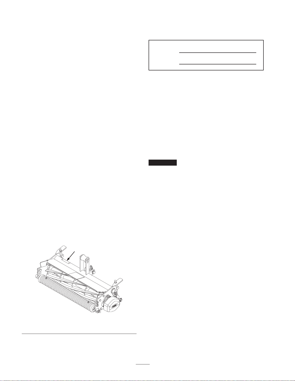
serial numbers of your product ready. Figure 1 illustrates
the location of the model and serial numbers on the
product.
1
Write the product model and serial numbers in the space
below:
Model No.
Serial No.
This manual identifies potential hazards and has special
safety messages that help you and others avoid personal
injury and even death. Danger, Warning, and Caution are
signal words used to identify the level of hazard. However,
regardless of the hazard, be extremely careful.
Danger signals an extreme hazard that will cause serious
injury or death if you do not follow the recommended
precautions.
Warning signals a hazard that may cause serious injury or
death if you do not follow the recommended precautions.
Caution signals a hazard that may cause minor or moderate
injury if you do not follow the recommended precautions.
This manual uses two other words to highlight information.
Important calls attention to special mechanical
information and Note: emphasizes general information
worthy of special attention.
Optional Equipment
Extended Micro Cut Bedknife Part No. 104-7720
Lo Cut Bedknife Part No. 93-4264
High Cut Bedknife Part No. 94-6392
Fairway Bedknife Part No. 94-6393
5 Blade Heavy Duty Reel Part No. 98-2181
8 Blade Heavy Duty Reel Part No. 98-2182
High Height-of-Cut Kit Part No. 99-1496
Wiehle Rear Roller Model No. 04488
Rear Roller Scraper Kit Part No. 95-1600
Groomer Model No. 04485
Rear Roller Brush Kit (for use with
Groomer Model No. 04485)
Rear Roller Brush Kit Model No. 04489
Front Roller Scraper/Brush Part No. 104-7731
Full Roller Assembly Part No. 104-2642
Model No. 04491
Figure 1
1. Location of the model and serial numbers
2001 by The Toro Company
8111 Lyndale Avenue South
Bloomington, MN 55420-1196
Note: Specifications and design subject to change without
notice.
All Rights Reserved
Printed in the USA
2
Page 3

Adjustments
4. Loosen locknuts retaining the left-hand bedbar pivot
housing (Fig. 2).
Note: Determine the left and right sides of the machine
from the normal operating position.
After the cutting unit is unboxed, use the following
procedures to ensure that the cutting units are adjusted
properly.
1. Check each end of the reel for grease. Grease should be
visibly evident in the reel bearings.
2. Ensure that all nuts and bolts are securely fastened.
3. Position the lift roller to match the suspension.
• Upper position for standard transport height
• Lower position for increased transport height
4. Check to make sure that the bedknife and reel are
parallel; refer to Adjusting the Bedknife to the Reel,
page 3.
Adjusting the Bedknife to the
Reel
1. Remove cutting units from traction unit and position on
a level work surface.
5. Rotate flange nuts (Fig. 2, inset), on top and bottom of
frame tab, clockwise or counterclockwise to raise or
lower end of bedbar, as required. Do not loosen bottom
flange nut. Tighten flangenuts against frame tab when
desired adjustment is attained.
6. Check adjustments by repeating steps 2 and 3.
7. When light contact on paper is evident at each end of
bedknife, tighten locknuts retaining pivot housing
securely.
2. Make sure reel contact is removed by turning bedknife
adjustment knob counterclockwise (Fig. 2).
1
Figure 2
1. Bedknife adjustment knob
2. Left-hand bedbar pivot
housing
3. On either end of front side of reel, insert a long strip of
newspaper between the reel and bedknife (Fig. 3).
While slowly rotating the reel forward, turn the
bedknife adjusting knob clockwise, one click at a time,
until the paper is pinched lightly on one end of the reel,
which results in a slight drag when the paper is pulled.
3. Flange nuts
4. Frame tab
3
4
3
2
Figure 3
Choosing Cutting Unit Attitude
There are four positions for the front roller brackets.
Position 1
Least aggressive; use for very soft and tender turf.
HOC Range: 0.094 (3/32)–0.84 (27/32) in. (2.4–21.3 mm)
Frame
Bracket
down
Position 1
3
Page 4

Position 2
Standard position; use for most conditions (factory setting).
HOC Range: 0.094 (3/32)–0.72 (23/32) in. (2.4–18.3 mm)
Note: A more aggressive setting may be required to
compensate for reel wear. (As the reel wears, the cutting
unit becomes less aggressive).
Note: The top frame hole and top bracket hole will yield
Position 2 (standard position).
Frame
Bracket
down
Position 2
Position 3
More aggressive; use on firm turf or higher height-of-cuts.
HOC Range: 0.094 (3/32)–0.62 (5/8) in. (2.4–15.7 mm)
Bracket
Frame
down
Leveling the Front Roller to the
Reel
1. Position the cutting unit on a flat, level surface.
2. Place a 1/4 inch or thicker plate under the reel blades
and against the front face of the bedknife.
Note: Be sure that the plate covers the full length of the
reel blades and three blades contact the plate.
3. Loosen the locknuts retaining the right front roller
bracket (Fig. 4).
2
1
Figure 4
1. Right front roller bracket 2. Upper right roller
mounting bolt
Position 3
Position 4
Most aggressive; use only on very firm greens or at the
higher height-of-cuts.
HOC Range: 0.094 (3/32)–0.50 (1/2) in. (2.4–12.7 mm)
Bracket
Frame
Position 4
Note: A more aggressive setting will increase grass
removal and provide a cleaner cut, but may cause increased
scalping and marking.
down
4. While holding the reel securely on the plate and
maintaining pressure on the front roller, rotate the upper
right roller mounting bolt (Fig. 4). This mounting bolt
has an offset, which when rotated, acts as an eccentric
(cam) to raise or lower the roller. On the bolt head there
is an I.D. dot which denotes the offset of the bolt. The
dot indicates in which direction the right end of the
roller moves when the bolt is turned.
Note: If additional adjustment is required, replace one
screw on the left-hand bracket with another eccentric bolt,
Part No. 93-2573. Ensure that both front roller brackets are
in the same hole.
5. To verify if the roller is level, try inserting a piece of
paper under each end of the roller.
6. When the roller is level, tighten the nuts securely.
4
Page 5

Adjusting the Top Shield
Height
1. Loosen bolts and nuts securing the shield to each side
plate.
2. Adjust the shield to the desired position and secure the
fasteners.
3. Repeat this procedure on the remaining cutting units
and adjust the top bar.
Note: The shield can be raised for extremely wet
conditions.
Adjusting the Top Bar
Adjust the top bar, under the rear shield, to ensure that
clippings are cleanly discharged from the reel area.
1. Loosen the screws securing the top bar. Insert a 0.06 in.
(1.5 mm) feeler gauge between the top of the reel and
bar and tighten the screws. Ensure that the bar and reel
are an equal distance apart across the complete reel.
2. Repeat the settings on the remaining cutting units.
Note: The bar is adjustable to compensate for changes in
turf conditions. The bar should be adjusted closer to the
reel when the turf is extremely wet. By contrast, adjust the
bar further away from the reel when turf conditions are dry.
The bar should be adjusted whenever the top shield height
is changed, the reel wears, or the reel is sharpened by
grinding.
profile. Therefore, benchsetting a cutting unit does not
equal the effective (actual) height of cut you achieve. You
need to determine how to adjust your cutter on the bench to
achieve a comparable height of cut to a cutting unit of a
different configuration, model, or brand.
3
1
2
Figure 5
1. Gauge bar
2. Roller bracket bolt
3. Height-of-cut knob
Adjusting the Height of Cut
1. Verify that the front roller is level and the
bedknife-to-reel contact is correct.
2. Turn the cutting unit over (90°) and rest it on the rear
roller and top rear tabs. Loosen the locknuts on the bolts
retaining the rear roller brackets (Fig. 5).
3. On the gauge bar (Part No. 13-8199), set the head of the
screw to the desired height of cut (Fig. 5). This
measurement is from the bar face to the underside of the
screw head.
4. Place the bar across the front and rear rollers and adjust
the height-of-cut knob (Fig. 5) until the underside of the
screw head engages the bedknife cutting edge.
Important Repeat this procedure on each end of the
bedknife and tighten the locknuts retaining the rear roller
brackets on each end.
Note: The cutting units will deliver differing effective
height of cuts depending on their configuration. Effective
cutting height may be influenced by the following factors:
turf conditions, roller profiles, cutting unit attitude, cutting
unit accessories, weight of cutting units, and bedknife
Operation
Note: Determine the left and right sides of the machine
from the normal operating position.
Cutting Unit Characteristics
The single knob bedknife-to-reel adjustment system
incorporated in this cutting unit simplifies the adjustment
procedure needed to deliver optimum mowing
performance. The precise adjustment possible with the
single knob/bedbar design gives the necessary control to
provide a continual self-sharpening action—thus
maintaining sharp cutting edges, ensuring good
quality-of-cut, and greatly reducing the need for routine
backlapping.
5
Page 6

Daily Adjustments of Cutting
Unit
Prior to mowing each day, or as required, each cutting unit
must be checked to verify proper bedknife-to-reel contact.
This must be performed even though quality of cut is
acceptable.
1. Lower the cutting units onto a hard surface, shut off the
engine, and remove the ignition key.
2. Slowly rotate the reel in a reverse direction, listening
for reel-to-bedknife contact. If no contact is evident,
turn the bedknife adjusting knob clockwise, one click at
a time, until light contact is felt and heard.
Note: The adjustment knob has detents corresponding to
0.0007 in. (0.018 mm) bedknife movement for each
indexed position.
3. If excessive contact is felt, turn the bedknife adjusting
knob counterclockwise, one click at a time until no
contact is evident. Then turn the bedknife adjusting
knob one click at a time clockwise, until light contact is
felt and heard.
Maintenance
Note: Determine the left and right sides of the machine
from the normal operating position.
Greasing the Bearings and
Bushings
Each cutting unit has 7 grease fittings that must be
lubricated regularly with No. 2 General Purpose Lithium
Base Grease.
The grease fitting locations and quantities are:
• Adjusting knob pivot point (Fig. 6)
• Reel bearings (2) (Fig. 6)
• Front and rear rollers (2 ea.) (Fig. 6)
Important Lubricating the cutting units immediately
after washing helps purge water out of the bearings and
increases bearing life.
1. Wipe each grease fitting with a clean rag.
Important Light contact is preferred at all times. If
light contact is not maintained, the bedknife/reel edges will
not sufficiently self-sharpen and dull cutting edges will
result after a period of operation. If excessive contact is
maintained, bedknife/reel wear will be accelerated, uneven
wear can result, and quality of cut may be adversely
affected.
Note: As the reel blades continue to run against the
bedknife, a slight burr will appear on the front cutting edge
surface along the full length of the bedknife. If a file is
occasionally run across the front edge to remove this burr,
improved cutting can be obtained.
After extended running, a ridge will eventually develop at
both ends of the bedknife. These notches must be rounded
off or filed flush with the cutting edge of the bedknife to
ensure smooth operation.
2. Grease the reel bearings (Fig. 6) until grease comes out
of the pressure relief.
3. Grease the front and rear roller bearings (Fig. 6) until
grease begins to show around the seal lips.
4. Grease the adjusting pivot point (Fig. 6).
Important Do not apply too much pressure or the
grease seals will be permanently damaged.
1
Figure 6
1. Pressure relief
5. Wipe excess grease away.
6
Page 7

Backlapping the Cutting Units
Caution
Contact with the reels or other moving parts can
result in personal injury.
Keep fingers, hands, and clothing away from the
reels or other moving parts.
1. Position the machine on a clean, level surface, lower the
cutting units, stop the engine, engage the parking brake,
and remove the ignition key.
2. Remove the reel motors from the cutting units and
disconnect and remove the cutting units from the lift
arms.
3. Connect the backlapping machine to the cutting unit by
inserting a piece of 3/8 in. square stock into the splined
coupling at the right end of the cutting unit.
Note: Additional instructions and procedures on
Backlapping are available in the Toro Sharpening Reel &
Rotary Mowers Manual, Form No. 80-300PT.
Note: For a better cutting edge, run a file across the front
face of the bedknife when the lapping operation is
completed. This will remove any burrs or rough edges that
may have built up on the cutting edge.
7
Page 8

The Toro General Commercial Products Warranty
A Two-Year Limited Warranty
Conditions and Products Covered
The Toro Company and its affiliate, Toro Warranty Company,
pursuant to an agreement between them, jointly warrant your 1996
or newer Toro Commercial Product (“Product”) purchased after
January 1, 1997, to be free from defects in materials or
workmanship for two years or 1500 operational hours*, whichever
occurs first. Where a warrantable condition exists, we will repair
the Product at no cost to you including diagnosis, labor, parts, and
transportation. This warranty begins on the date the Product is
delivered to the original retail purchaser.
* Product equipped with hour meter
Instructions for Obtaining Warranty Service
You are responsible for notifying the Commercial Products
Distributor or Authorized Commercial Products Dealer from whom
you purchased the Product as soon as you believe a warrantable
condition exists.
If you need help locating a Commercial Products Distributor or
Authorized Dealer, or if you have questions regarding your
warranty rights or responsibilities, you may contact us at:
Toro Commercial Products Service Department
Toro Warranty Company
8111 Lyndale Avenue South
Bloomington, MN 55420-1196
952-888-8801 or 800-982-2740
E-mail: commercial.service@toro.com
Owner Responsibilities
As the Product owner, you are responsible for required maintenance and adjustments stated in your operator’s manual. Failure
to perform required maintenance and adjustments can be grounds
for disallowing a warranty claim.
Items and Conditions Not Covered
Not all product failures or malfunctions that occur during the
warranty period are defects in materials or workmanship. This
express warranty does not cover the following:
• Product failures which result from the use of non-Toro
replacement parts, or from installation and use of add-on,
modified, or unapproved accessories
• Product failures which result from failure to perform required
maintenance and/or adjustments
• Product failures which result from operating the Product in an
abusive, negligent or reckless manner
• Parts subject to consumption through use unless found to be
defective. Examples of parts which are consumed, or used up,
during normal Product operation include, but are not limited to,
blades, reels, bedknives, tines, spark plugs, castor wheels,
tires, filters, belts, etc.
• Failures caused by outside influence. Items considered to be
outside influence include, but are not limited to, weather,
storage practices, contamination, use of unapproved coolants,
lubricants, additives, or chemicals, etc.
• Normal “wear and tear” items. Normal “wear and tear”
includes, but is not limited to, damage to seats due to wear or
abrasion, worn painted surfaces, scratched decals or windows, etc.
Parts
Parts scheduled for replacement as required maintenance are
warranted for the period of time up to the scheduled replacement
time for that part.
Parts replaced under this warranty become the property of Toro.
T oro will make the final decision whether to repair any existing part
or assembly or replace it. Toro may use factory remanufactured
parts rather than new parts for some warranty repairs.
General Conditions
Repair by an Authorized Toro Distributor or Dealer is your sole
remedy under this warranty.
Neither The Toro Company nor Toro Warranty Company is
liable for indirect, incidental or consequential damages in
connection with the use of the T oro Products covered by this
warranty, including any cost or expense of providing substitute equipment or service during reasonable periods of
malfunction or non-use pending completion of repairs under
this warranty. Except for the Emissions warranty referenced
below, if applicable, there is no other express warranty. All
implied warranties of merchantability and fitness for use are
limited to the duration of this express warranty.
Some states do not allow exclusions of incidental or consequential
damages, or limitations on how long an implied warranty lasts, so
the above exclusions and limitations may not apply to you.
This warranty gives you specific legal rights, and you may also
have other rights which vary from state to state.
Note regarding engine warranty: The Emissions Control
System on your Product may be covered by a separate warranty
meeting requirements established by the U.S. Environmental
Protection Agency (EPA) and/or the California Air Resources
Board (CARB). The hour limitations set forth above do not apply to
the Emissions Control System Warranty. Refer to the Engine
Emission Control Warranty Statement printed in your operator’s
manual or contained in the engine manufacturer’s documentation
for details.
Countries Other than the United States or Canada
Customers who have purchased Toro products exported from the United States or Canada should contact their Toro Distributor (Dealer)
to obtain guarantee policies for your country, province, or state. If for any reason you are dissatisfied with your Distributor’s service or
have difficulty obtaining guarantee information, contact the Toro importer. If all other remedies fail, you may contact us at Toro Warranty
Company.
Part No. 374-0031 Rev. –
 Loading...