

Page 1

Greensmaster) 3250-D
Traction Unit
Model No. 04383—270000001 and Up
Form No. 3358–316 Rev B
Operator’s Manual
English (EN, GB)
Page 2

Warning
CALIFORNIA
Proposition 65 Warning
Diesel engine exhaust and some of its constituents
are known to the State of California to cause
cancer, birth defects, and other reproductive harm.
Important The engine in this product is not equipped
with a spark arrester muffler. It is a violation of California
Public Resource Code Section 4442 to use or operate this
engine on any forest-covered, brush-covered, or
grass-covered land as defined in CPRC 4126. Other states
or federal areas may have similar laws.
This spark ignition system complies with Canadian
ICES-002.
Ce système d’allumage par étincelle de véhicule est
conforme à la norme NMB-002 du Canada.
Contents
Page
Introduction 3. . . . . . . . . . . . . . . . . . . . . . . . . . . . . . . .
Safety 3. . . . . . . . . . . . . . . . . . . . . . . . . . . . . . . . . . . . .
Safe Operating Practices 3. . . . . . . . . . . . . . . . . . . .
Toro Riding Mower Safety 5. . . . . . . . . . . . . . . . . .
Sound Pressure Level 6. . . . . . . . . . . . . . . . . . . . . .
Sound Power Level 6. . . . . . . . . . . . . . . . . . . . . . .
Vibration Level 6. . . . . . . . . . . . . . . . . . . . . . . . . . .
Safety and Instruction Decals 7. . . . . . . . . . . . . . . .
Specifications 11. . . . . . . . . . . . . . . . . . . . . . . . . . . . . . .
General Specifications 11. . . . . . . . . . . . . . . . . . . . .
Setup 11. . . . . . . . . . . . . . . . . . . . . . . . . . . . . . . . . . . . .
Loose Parts 11. . . . . . . . . . . . . . . . . . . . . . . . . . . . . .
Installing the Front Wheels 12. . . . . . . . . . . . . . . . .
Installing the Rear Wheel 12. . . . . . . . . . . . . . . . . . .
Mounting the Seat 13. . . . . . . . . . . . . . . . . . . . . . . .
Activating and Charging the Battery 13. . . . . . . . . .
Installing the Steering Wheel 14. . . . . . . . . . . . . . . .
Installing Breather Extension and Reservoir Cap 15.
Mounting the Front Rollers 15. . . . . . . . . . . . . . . . .
Adjusting Carrier Frame Rollers 15. . . . . . . . . . . . .
Installing the Cutting Units 15. . . . . . . . . . . . . . . . .
Adjusting the Transport Height 18. . . . . . . . . . . . . .
Before Operating 20. . . . . . . . . . . . . . . . . . . . . . . . . . . .
Checking the Engine Oil 20. . . . . . . . . . . . . . . . . . .
Filling the Fuel Tank 21. . . . . . . . . . . . . . . . . . . . . .
Checking the Cooling System 21. . . . . . . . . . . . . . .
Servicing the Hydraulic System Fluid 22. . . . . . . . .
W 2007 by The Toro Company
8111 Lyndale Avenue South
Bloomington, MN 55420-1196
Draining Water from Fuel Filter/Water Separator 23
Checking the Tire Pressure 23. . . . . . . . . . . . . . . . . .
Checking the Reel-to-Bedknife Contact 23. . . . . . . .
Checking the Torque of the Wheel Nuts 23. . . . . . .
Operation 24. . . . . . . . . . . . . . . . . . . . . . . . . . . . . . . . . .
Think Safety First 24. . . . . . . . . . . . . . . . . . . . . . . . .
Controls 24. . . . . . . . . . . . . . . . . . . . . . . . . . . . . . . .
Break-In Period 26. . . . . . . . . . . . . . . . . . . . . . . . . .
Starting and Stopping the Machine 26. . . . . . . . . . .
Bleeding the Fuel System 27. . . . . . . . . . . . . . . . . . .
Testing the Safety Interlock System 27. . . . . . . . . . .
Setting the Reel Speed 27. . . . . . . . . . . . . . . . . . . . .
Preparing the Machine for Mowing 28. . . . . . . . . . .
Training Period 28. . . . . . . . . . . . . . . . . . . . . . . . . . .
Before Mowing 28. . . . . . . . . . . . . . . . . . . . . . . . . . .
Mowing Procedures 28. . . . . . . . . . . . . . . . . . . . . . .
Transport Operation 29. . . . . . . . . . . . . . . . . . . . . . .
Inspection and Clean-Up After Mowing 29. . . . . . .
Towing the Traction Unit 30. . . . . . . . . . . . . . . . . . .
Maintenance 31. . . . . . . . . . . . . . . . . . . . . . . . . . . . . . . .
Recommended Maintenance Schedule 31. . . . . . . . .
Daily Maintenance Checklist 32. . . . . . . . . . . . . . . .
Lubrication 33. . . . . . . . . . . . . . . . . . . . . . . . . . . . . .
General Air Cleaner Maintenance 34. . . . . . . . . . . .
Servicing Air Cleaner 34. . . . . . . . . . . . . . . . . . . . . .
Cleaning the Radiator Screen 34. . . . . . . . . . . . . . . .
Engine Oil 34. . . . . . . . . . . . . . . . . . . . . . . . . . . . . .
Fuel Filter/Water Separator 35. . . . . . . . . . . . . . . . . .
Adjusting the Throttle Control 35. . . . . . . . . . . . . . .
Adjusting the Idle Speed 36. . . . . . . . . . . . . . . . . . .
Hydraulic Oil 36. . . . . . . . . . . . . . . . . . . . . . . . . . . .
Checking the Hydraulic Lines and Hoses 36. . . . . . .
Adjusting the Brakes 36. . . . . . . . . . . . . . . . . . . . . .
Adjusting the Transmission for Neutral 37. . . . . . . .
Adjusting the Transport Speed 37. . . . . . . . . . . . . . .
Adjusting the Mowing Speed 38. . . . . . . . . . . . . . . .
Adjusting the Cutting Unit Lift/Drop 38. . . . . . . . . .
Adjusting the Belt 38. . . . . . . . . . . . . . . . . . . . . . . . .
Servicing the Battery 39. . . . . . . . . . . . . . . . . . . . . .
Storing the Battery 39. . . . . . . . . . . . . . . . . . . . . . . .
Fuses 40. . . . . . . . . . . . . . . . . . . . . . . . . . . . . . . . . . .
Backlapping 40. . . . . . . . . . . . . . . . . . . . . . . . . . . . .
Electrical Schematic 41. . . . . . . . . . . . . . . . . . . . . . .
Hydraulic Schematic 42. . . . . . . . . . . . . . . . . . . . . .
The Toro General Commercial Products Warranty 44. .
All Rights Reserved
Printed in the USA
2
Page 3
Introduction
Safety
Read this manual carefully to learn how to operate and
maintain your product properly. The information in this
manual can help you and others avoid injury and product
damage. Although Toro designs and produces safe
products, you are responsible for operating the product
properly and safely.
Whenever you need service, genuine Toro parts, or
additional information, contact an Authorized Service
Dealer or Toro Customer Service and have the model and
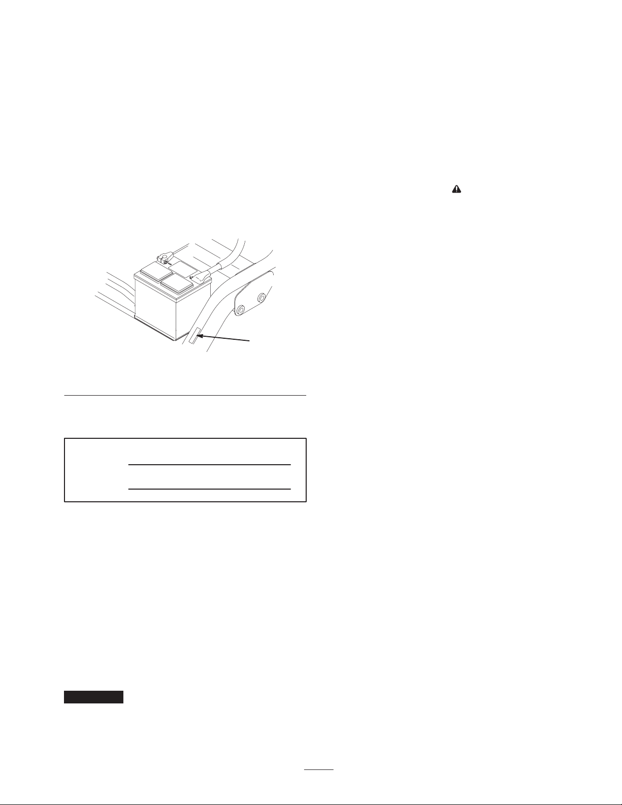
serial numbers of your product ready. Figure 1 illustrates
the location of the model and serial numbers on the
product.
1
Figure 1
1. Location of the model and serial numbers
Write the product model and serial numbers in the space
below:
This machine meets or exceeds CEN standard EN
836:1997, ISO standard 5395:1990, and ANSI
B71.4-2004 specifications in effect at the time of
production when 40 lb. of ballast is added to the rear
wheel.
Improper use or maintenance by the operator or owner
can result in injury. To reduce the potential for injury,
comply with these safety instructions and always pay
attention to the safety alert
CAUTION, WARNING, or DANGER—“personal
safety instruction.” Failure to comply with the
instruction may result in personal injury or death.
symbol, which means
Safe Operating Practices
The following instructions are from the CEN standard EN
836:1997, ISO standard 5395:1990, and ANSI B71.4-2004.
Training
• Read the Operator’s Manual and other training material
carefully. Be familiar with the controls, safety signs,
and the proper use of the equipment.
• Never allow children or people unfamiliar with these
instructions to use or service the mower. Local
regulations may restrict the age of the operator.
• Never mow while people, especially children, or pets
are nearby.
Model No.
Serial No.
This manual identifies potential hazards and has special
safety messages that help you and others avoid personal
injury and even death. Danger, Warning, and Caution are
signal words used to identify the level of hazard. However,
regardless of the hazard, be extremely careful.
Danger signals an extreme hazard that will cause serious
injury or death if you do not follow the recommended
precautions.
Warning signals a hazard that may cause serious injury or
death if you do not follow the recommended precautions.
Caution signals a hazard that may cause minor or moderate
injury if you do not follow the recommended precautions.
This manual uses two other words to highlight information.
Important calls attention to special mechanical
information and Note: emphasizes general information
worthy of special attention.
• Keep in mind that the operator or user is responsible for
accidents or hazards occurring to other people or their
property.
• Do not carry passengers.
• All drivers and mechanics should seek and obtain
professional and practical instruction. The owner is
responsible for training the users. Such instruction
should emphasize:
– the need for care and concentration when working
with ride-on machines;
– control of a ride-on machine sliding on a slope will
not be regained by the application of the brake. The
main reasons for loss of control are:
• insufficient wheel grip;
• being driven too fast;
• inadequate braking;
• the type of machine is unsuitable for its task;
• lack of awareness of the effect of ground
conditions, especially slopes;
• incorrect hitching and load distribution.
3
Page 4

• The owner/user can prevent and is responsible for
accidents or injuries occurring to himself or herself,
other people, or property.
Preparation
• While mowing, always wear substantial footwear, long
trousers, hard hat, safety glasses, and ear protection.
Long hair, loose clothing, or jewelry may get tangled in
moving parts. Do not operate the equipment when
barefoot or wearing open sandals.
• Thoroughly inspect the area where the equipment is to
be used and remove all objects which may be thrown by
the machine.
• Warning—Fuel is highly flammable. Take the
following precautions:
– Store fuel in containers specifically designed for this
purpose.
– Refuel outdoors only and do not smoke while
refuelling.
– Add fuel before starting the engine. Never remove
the cap of the fuel tank or add fuel while the engine
is running or when the engine is hot.
– If fuel is spilled, do not attempt to start the engine
but move the machine away from the area of
spillage and avoid creating any source of ignition
until fuel vapors have dissipated.
– Replace all fuel tanks and container caps securely.
• Replace faulty silencers.
• Evaluate the terrain to determine what accessories and
attachments are needed to properly and safely perform
the job. Only use accessories and attachments approved
by the manufacturer.
• Check that operator’s presence controls, safety switches
and shields are attached and functioning properly. Do
not operate unless they are functioning properly.
– machine speeds should be kept low on slopes and
during tight turns;
– stay alert for humps and hollows and other hidden
hazards;
– never mow across the face of the slope, unless the
mower is designed for this purpose.
• Stay alert for holes in the terrain and other hidden
hazards.
• Watch out for traffic when crossing or near roadways.
• Stop the blades rotating before crossing surfaces other
than grass.
• When using any attachments, never direct discharge of
material toward bystanders nor allow anyone near the
machine while in operation.
• Never operate the machine with damaged guards,
shields, or without safety protective devices in place. Be
sure all interlocks are attached, adjusted properly, and
functioning properly.
• Do not change the engine governor settings or
overspeed the engine. Operating the engine at excessive
speed may increase the hazard of personal injury.
• Before leaving the operator’s position:
– stop on level ground;
– disengage the power take-off and lower the
attachments;
– change into neutral and set the parking brake;
– stop the engine and remove the key.
• Disengage drive to attachments when transporting or
not in use.
• Stop the engine and disengage drive to attachment:
– before refuelling;
– before removing the grass catcher/catchers;
Operation
• Do not operate the engine in a confined space where
dangerous carbon monoxide fumes can collect.
• Mow only in daylight or in good artificial light.
• Before attempting to start the engine, disengage all
blade attachment clutches, shift into neutral, and engage
the parking brake.
• Remember there is no such thing as a safe slope. Travel
on grass slopes requires particular care. To guard
against overturning:
– do not stop or start suddenly when going up or
downhill;
– before making height adjustment unless adjustment
can be made from the operator’s position.
– before clearing blockages;
– before checking, cleaning or working on the mower;
– after striking a foreign object or if an abnormal
vibration occurs. Inspect the mower for damage and
make repairs before restarting and operating the
equipment.
• Reduce the throttle setting before stopping engine and,
if the engine is provided with a shut-off valve, turn the
fuel off at the conclusion of mowing.
• Keep hands and feet away from the cutting units.
4
Page 5

• Look behind and down before backing up to be sure of
a clear path.
• Slow down and use caution when making turns and
crossing roads and sidewalks. Stop reels if not mowing.
• Do not operate the mower under the influence of
alcohol or drugs
• Use care when loading or unloading the machine into a
trailer or truck
• Use care when approaching blind corners, shrubs, trees,
or other objects that may obscure vision.
Maintenance and Storage
• Keep hands and feet away from moving parts. If
possible, do not make adjustments with the engine
running.
• Charge batteries in an open well ventilated area, away
from spark and flames. Unplug charger before
connecting or disconnecting from battery. Wear
protective clothing and use insulated tools.
Toro Riding Mower Safety
The following list contains safety information specific to
Toro products or other safety information that you must
know that is not included in the CEN, ISO, or ANSI
standard.
• Keep all nuts, bolts and screws tight to be sure the
equipment is in safe working condition.
• Never store the equipment with fuel in the tank inside a
building where fumes may reach an open flame or
spark.
• Allow the engine to cool before storing in any
enclosure.
• To reduce the fire hazard, keep the engine, silencer,
battery compartment and fuel storage area free of grass,
leaves, or excessive grease.
• Check the grass catcher frequently for wear or
deterioration.
• Keep all parts in good working condition and all
hardware and hydraulic fittings tightened. Replace all
worn or damaged parts and decals.
• If the fuel tank has to be drained, do this outdoors.
• Be careful during adjustment of the machine to prevent
entrapment of the fingers between moving blades and
fixed parts of the machine.
• On multi-reel machines, take care as rotating one reel
can cause other reels to rotate.
• Disengage drives, lower the cutting units, set parking
brake and stop engine. Wait for all movement to stop
before adjusting, cleaning or repairing.
• Clean grass and debris from cutting units, drives,
mufflers, and engine to help prevent fires. Clean up oil
or fuel spillage.
This product is capable of amputating hands and feet and
throwing objects. Always follow all safety instructions to
avoid serious injury or death.
Use of this product for purposes other than its intended use
could prove dangerous to user and bystanders.
• Know how to stop the engine quickly.
• Do not operate the machine while wearing tennis shoes
or sneakers.
• Wearing safety shoes and long pants is advisable and
required by some local ordinances and insurance
regulations.
• The operator must be skilled and trained in how to drive
on hillsides. Failure to use caution on slopes or hills
may cause loss of control and cause the vehicle to tip or
roll, possibly resulting in personal injury or death.
• Handle gasoline carefully. Wipe up any spills.
• Check the safety interlock switches daily for proper
operation. If a switch should fail, replace the switch
before operating the machine.
• Before starting the engine, sit on the seat, depress the
lift pedal, and release it to ensure that the cutting units
are disengaged. Verify that the traction system is in
neutral and the parking brake is set.
• Using the machine demands attention. To prevent loss
of control:
– Do not drive close to sand traps, ditches, creeks, or
other hazards.
• Use jack stands to support components when required.
• Carefully release pressure from components with stored
energy.
• Disconnect battery before making any repairs.
Disconnect the negative terminal first and the positive
last. Reconnect positive first and negative last.
• Use care when checking the reels. Wear gloves and use
caution when servicing them.
– Reduce speed when making sharp turns. Avoid
sudden stops and starts.
– When near or crossing roads, always yield the
right-of-way.
– Apply the service brakes when going downhill to
keep forward speed slow and to maintain control of
the machine.
5
Page 6

• The grass baskets must be in place during operation of
the reels or thatchers for maximum safety. Shut the
engine off before emptying the baskets.
• Raise the cutting units when driving from one work
area to another.
• Do not touch the engine, muffler, or exhaust pipe while
the engine is running or soon after it has stopped
because these areas could be hot enough to cause burns.
• The engine must be shut off before checking the oil or
adding oil to the crankcase.
• To ensure safety and accuracy, have an Authorized Toro
Distributor check the maximum engine speed with a
tachometer. Maximum governed engine speed should be
2900 RPM.
• If major repairs are ever needed or if assistance is
desired, contact an Authorized Toro Distributor.
• Stay clear of the rotating screen at the side of the engine
to prevent direct contact with your body or clothing.
• If the engine stalls or loses headway and cannot make it
to the top of a slope, do not turn the machine around.
Always back slowly, straight down the slope.
• When a person or pet appears unexpectedly in or near
the mowing area, stop mowing. Careless operation,
combined with terrain angles, ricochets, or improperly
positioned guards can lead to thrown object injuries. Do
not resume mowing until the area is cleared.
• If the machine is equipped with an optional ROPS (Roll
Over Protection System), always use the seat belt when
operating the machine.
• Before getting off of the seat, move the functional
control lever to neutral (N), raise the cutting units and
wait for the reels to stop spinning. Set the parking
brake. Stop the engine and remove the key from the
ignition switch.
• Whenever the machine is left unattended, make sure
that the cutting units are fully raised and the reels are
not spinning, the key is removed from the ignition
switch, and the parking brake is set.
Maintenance and Storage
• Use only Toro-approved attachments and replacement
parts. The warranty may be voided if used with
unapproved attachments.
Sound Pressure Level
This unit has an equivalent continuous A-weighted sound
pressure at the operator ear of: 84 dBA, based on
measurements of identical machines per Directive
98/37/EC and amendments.
Sound Power Level
This unit has a guaranteed sound power level of: 105 dBA,
based on measurements of identical machines per Directive
2000/14/EC and amendments.
Vibration Level
Hand-Arm
This unit does not exceed a vibration level of 2.5 m/s2 at
the hands based on measurements of identical machines per
ISO 5349 procedures.
• Make sure all hydraulic line connectors are tight and all
hydraulic hoses and lines are in good condition before
applying pressure to the system.
• Keep your body and hands away from pin hole leaks or
nozzles that eject hydraulic fluid under high pressure.
Use paper or cardboard, not your hands, to search for
leaks. Hydraulic fluid escaping under pressure can have
sufficient force to penetrate the skin and cause serious
injury.
• Before disconnecting or performing any work on the
hydraulic system, all pressure in the system must be
relieved by stopping the engine and lowering the cutting
units and attachments to the ground.
• Check all fuel lines for tightness and wear on a regular
basis. Tighten or repair them as needed.
• If the engine must be running to perform a maintenance
adjustment, keep hands, feet, clothing, and any parts of
the body away from the cutting units, attachments, and
any moving parts, especially the screen at the side of the
engine. Keep everyone away.
Whole Body
This unit does not exceed a vibration level of 0.5 m/s2 at
the posterior based on measurements of identical machines
per ISO 2631 procedures.
6
Page 7

Safety and Instruction Decals
Safety decals and instructions are easily visible to the operator and are located near any area
of potential danger. Replace any decal that is damaged or lost.
93-8068
1. Read the operator’s manual for instructions on how to lock and
unlock the steering arm.
104-7728
93-6686
1. Hydraulic oil 2. Read the Operator’s
Manual.
114-4614
93-9051
1. Read the operator’s manual.
93-6681
1. Cutting/dismemberment hazard—stay away from moving parts.
93-6689
1. Danger—do not sit on the plastic shroud.
7
Page 8
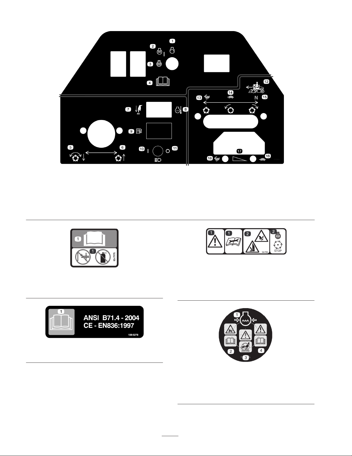
1. Engine start
2. Engine preheat/on
3. Engine stop
4. Read the Operator’s Manual.
5. Lower the reels and engage
6. Raise the reels
7. High temperature override
8. Engine coolant temperature
9. Water in the fuel indicator
light
93-7275
1. Read the operator’s manual—do not use starting fluid to start
the engine.
107-9529
10. Headlights On
11. Headlights Off
12. Functional control lever
13. Use for transport.
14. Use for mowing.
1. Danger—read the
operator’s manual before
performing any
maintenance.
15. Neutral—Use for
backlapping reels
16. Throttle—slow
17. Throttle—continuous
variable setting
18. Throttle—fast
104-7729 (for CE)
2. Cutting hazard to hands
or feet—wait until all
machine components
have stopped before
touching them.
108-5278
1. Warning—read the Operator’s Manual.
1. Engine coolant under
pressure
2. Explosion hazard—read
the Operator’s Manual.
8
106-5976
3. Warning—do not touch
the hot surface.
4. Warning—read the
Operator’s Manual.
Page 9
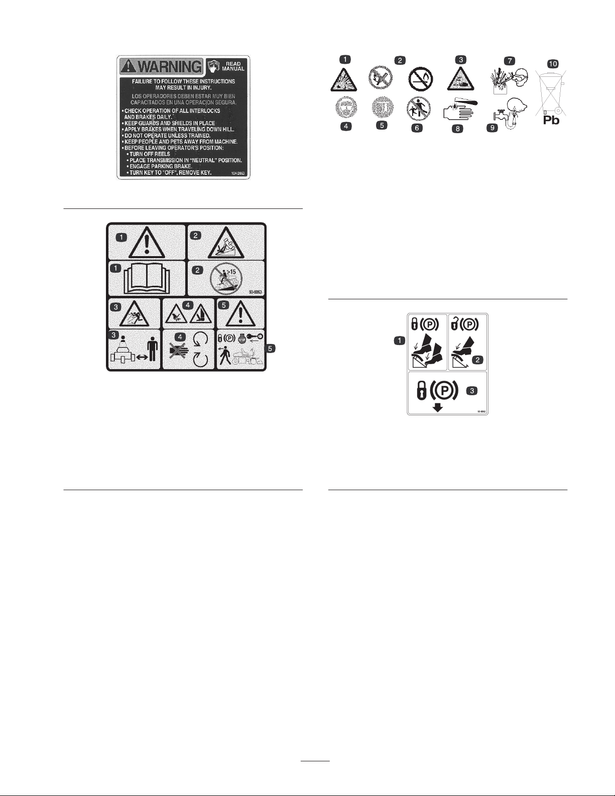
104-2053
93-8063
Replaces 104–2053 or CE
1. Warning—read the Operator’s Manual.
2. Tipping hazard—do not use the machine on a slope greater
than 15 degrees.
3. Thrown object hazard—stay a safe distance from the machine.
4. Cutting hazard of hand or foot—stay away from moving parts.
5. Warning—lock the parking brake, stop the engine, and remove
the ignition key before leaving the machine.
Battery Symbols
Some or all of these symbols are on your battery.
1. Explosion hazard
2. No fire, open flames, or
smoking.
3. Caustic liquid/chemical
burn hazard
4. Wear eye protection
5. Read the Operator’s
Manual.
6. Keep bystanders a safe
distance from the battery.
7. Wear eye protection;
explosive gases can
cause blindness and
other injuries
8. Battery acid can cause
blindness or severe
burns.
9. Flush eyes immediately
with water and get
medical help fast.
10. Contains lead; do not
discard.
93-8062
1. To lock the parking brake, press the brake pedal and parking
brake.
2. To unlock the parking brake, press the brake pedal.
3. Locks the parking brake
9
Page 10

1. Height of cut
2. 5 blade reel
3. 8 blade reel
4. 11 blade reel
114-4615
5. Reel—mowing speed
6. Fast
7. Continuous variable setting
8. Slow
10
Page 11

Specifications
General Specifications
Width of cut 59 in. (150 cm)
Wheel tread 50.5 in. (128 cm)
Wheel base 48.6 in. (123 cm)
Overall length (w/baskets) 93.9 in. (238 cm)
Overall width 68 in. (173 cm)
Overall height 50.5 in. (128 cm)
Weight w/reels
(8 Blade 4 Bolt)
1338 lb. (608 kg)
Setup
Loose Parts
Note: Use the chart below to verify all parts have been shipped.
Description Qty. Use
Wheel nuts
Wheels
Wheel hub
Wheel nuts
Wheel
Wheel bolt
Locknut
Spacers
Seat
Nut, 5/16 in.
8
2
1
4
1
1
1
2
1
4
Mounting the front wheels
Mounting the rear wheel
Mounting the seat to the seat base
Steering wheel
Cap
Screw
Pull link 2 Mounting the front rollers
Gauge bar
Screw, #10 x 5/8 in.
Nut, #10
Breather extension 1 Mount to the hydraulic reservoir
11
1
1
1
1
1
1
Mounting the steering wheel
Setting the height-of-cut
Page 12
Description UseQty.
Anti-scalp roller
Pull link assembly
Roller shaft
Spacer
Washer
Lock nut, 3/8–16
Offset Lift Hook 1 Mount to cutting unit Models 04610 & 04611.
Capscrews, M10–1.5 2
Grass Basket 3 Mount to the pull frame.
Ignition key 2
Service decal 11
Operator’s manual (traction unit)
Operator’s manual (engine)
Operator video 1 Watch before operating the machine.
Parts Catalog
Certificate of compliance
Pre-delivery sheet
Noise certificate
6
6
6
6
12
6
2
1
1
1
1
1
Mount the front rollers
Use to mount offset lift hook to cutting unit
Models 04610 & 04611.
Affix appropriate language decal over English
service decal (100-3150).
Read before operating the machine.
Note: Mounting fasteners for the Greensmaster 3250-D cutting units are included with the cutting units.
Installing the Front Wheels
Mount the front wheels and torque the mounting nuts to
70–90 ft.-lb.
1
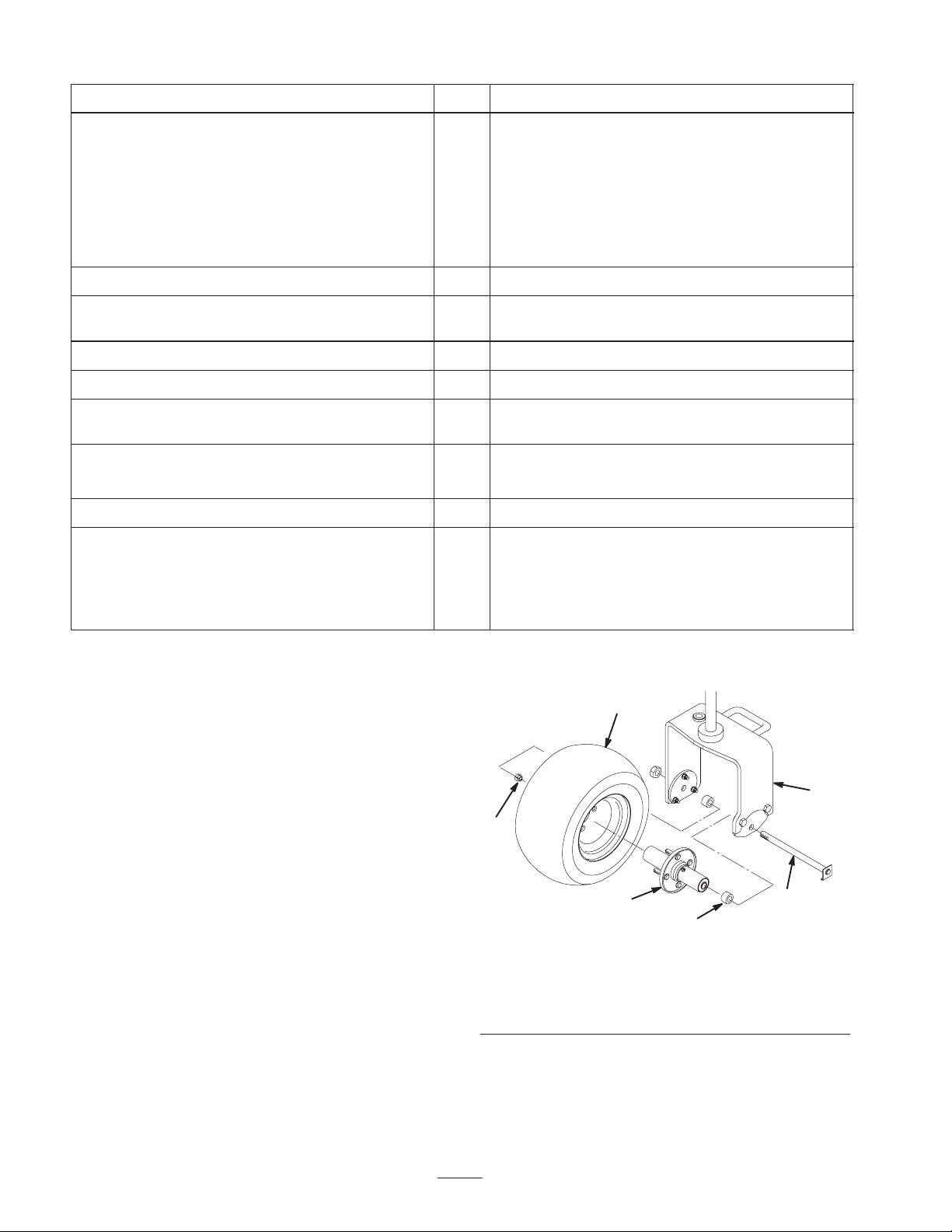
Installing the Rear Wheel
1. Mount the wheel hub to the rear wheel rim with 4
mounting nuts (Fig. 2). Torque the nuts to 70–90 ft.-lb.
2. Remove the wheel bolt and locknut from the wheel
mounting holes in the rear castor fork (Fig. 2).
3. Install the rear wheel into the castor fork. Insert the
wheel bolt into one of the castor fork mounting holes,
install a spacer (supplied in loose parts), and slide the
bolt through the wheel.
4. Install another spacer onto the bolt and route the bolt
through the remaining castor fork mounting hole.
5. Position the bend of the wheel bolt head under the
bottom edge of the adapter plate (Fig. 2). Install and
tighten the locknut to secure the wheel to the castor
fork. Do not overtighten the locknut as the wheel must
rotate freely.
3
2
6
Figure 2
1. Rear wheel
2. Hub
3. Nut
6. Wipe the grease fitting clean on the wheel assembly.
Pump grease into the wheel hub until grease is seen
exiting at both hub bearings. Wipe up excess grease.
4. Rear castor fork
5. Wheel bolt
6. Spacer (2)
4
5
12
Page 13
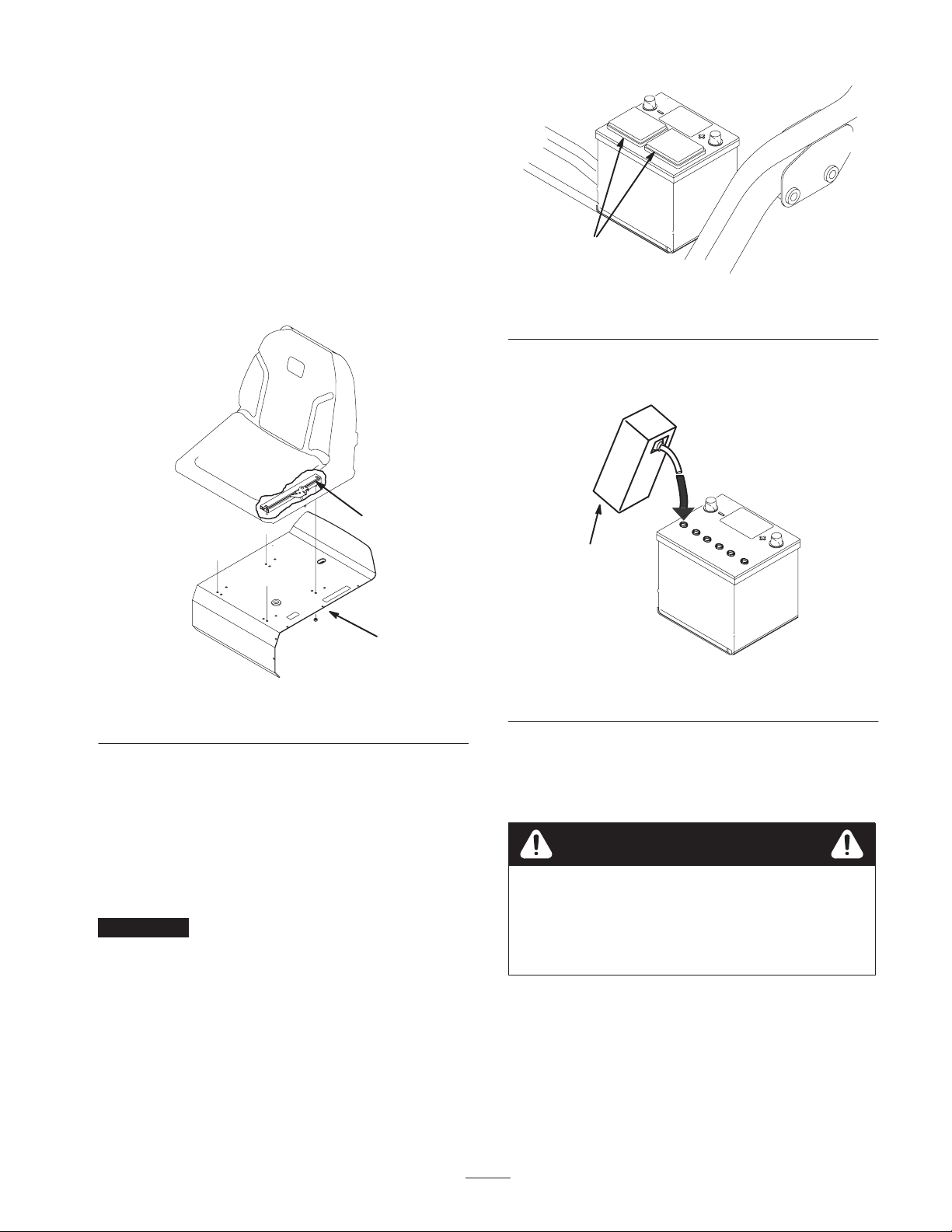
Mounting the Seat
Note: Mount the seat slides in the front set of mounting
holes to gain an additional 3 in. (7.6 cm) in the forward
adjustment, or in the rear mounting holes for an additional
3 in. (7.6 cm) in the rearward adjustment.
1. Remove the locknuts securing the seat slides to the
plywood shipping base. Discard the locknuts.
2. Connect the wire harness to the seat switch.
1
3. Secure the seat slides to the seat support with 4 locknuts
(5/16 in.) supplied in the loose parts (Fig. 3).
2
1
Figure 3
1. Seat support 2. Seat slide
Figure 4
1. Vent caps
3. Carefully fill each cell with electrolyte until the plates
are covered with about 1/4 inch (6 mm) of fluid.
1
Figure 5
1. Electrolyte
Activating and Charging the
Battery
Use only electrolyte (1.265 Specific Gravity) to fill battery
initially.
1. Remove the battery from the machine.
Important Do not add electrolyte while the battery is in
the machine. You could spill it, causing corrosion.
2. Clean the top of the battery and remove the vent caps
(Fig. 4).
4. Allow approximately 20 to 30 minutes for the
electrolyte to soak into the plates. Refill as necessary to
bring the electrolyte to within about 1/4 inch (6 mm) of
the bottom of the fill well (Fig. 5).
Warning
Charging the battery produces gasses that can
explode.
Never smoke near the battery and keep sparks and
flames away from battery.
5. Connect a 3 to 4 amp battery charger to the battery
posts. Charge the battery at a rate of 3 to 4 amps until
the specific gravity is 1.250 or higher and the
temperature is at least 60_F (16_C) with all sells
gassing freely.
6. When the battery is charged, disconnect the charger
from the electrical outlet and battery posts.
13
Page 14
Note: After the battery has been activated, add only
distilled water to replace normal loss, although
maintenance–free batteries should not require water under
normal operating conditions.
Warning
CALIFORNIA
1
Proposition 65 Warning
Battery posts, terminals, and related accessories
contain lead and lead compounds, chemicals
known to the State of California to cause cancer
and reproductive harm. Wash hands after
handling.
Warning
Battery terminals or metal tools could short
against metal tractor components causing sparks.
Sparks can cause the battery gasses to explode,
resulting in personal injury.
• When removing or installing the battery, do not
allow the battery terminals to touch any metal
parts of the tractor.
• Do not allow metal tools to short between the
battery terminals and metal parts of the tractor.
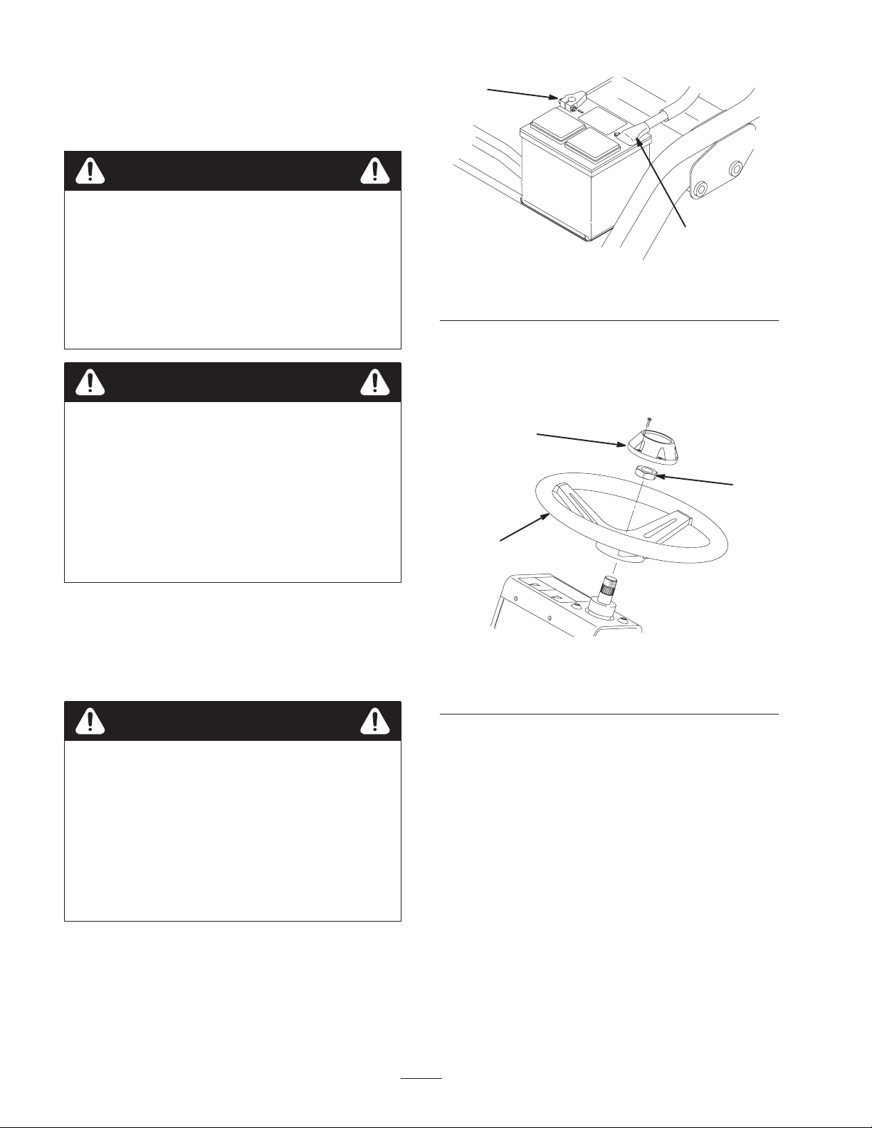
7. First, install the positive cable (red) to the positive (+)
terminal and then the negative cable (black) to the
negative (–) terminal of the battery and secure them
with the bolts and nuts (Fig. 6). Slide the rubber boot
over the positive terminal to prevent a possible short
from occurring.
2
Figure 6
1. Negative (–) 2. Positive (+)
Installing the Steering Wheel
1. Slide the steering wheel onto the steering shaft.
3
1
Figure 7
1. Steering wheel
2. Jam nut
3. Cap
2
Warning
Incorrect battery cable routing could damage the
tractor and cables causing sparks. Sparks can
cause the battery gasses to explode, resulting in
personal injury.
• Always disconnect the negative (black) battery
cable before disconnecting the positive (red)
cable.
• Always connect the positive (red) battery cable
before connecting the negative (black) cable.
2. Secure the steering wheel to the shaft with the jam nut
(Fig. 7) and tighten it to 20–26 ft.-lb.
3. Install the cap to the steering wheel with the screw
(Fig. 7).
14
Page 15

Installing the Breather
Adjusting Carrier Frame
Extension and Reservoir Cap
1. Remove the breather cap from the hydraulic reservoir
(Fig. 8).
3
1
Figure 8
1. Hydraulic reservoir
2. Breather cap
2. Thread the breather extension into the reservoir (Fig. 8).
3. Thread the breather cap into the breather extension
(Fig. 8).
4. Remove and discard the shipping cap from the
hydraulic reservoir. Install the cap secured to the
machine.
3. Breather extension
4. Reservoir cap
2
4
Mounting the Front Rollers
Rollers
1. Position the traction unit on a level surface and lower
the cutting unit carrier frames to the floor.
2. Verify that there is 1/2 in. (13 mm) clearance between
the carrier frame rollers and the floor.
3. If an adjustment is required, loosen the jam nut on the
carrier frame stop screw (Fig. 10) and rotate the screw
up or down to raise or lower the carrier frame. Tighten
the jam nut after adjustment is attained.
2
1
1. Mount an anti-scalp roller and a pull link assembly to
the outer end of each front carrier frame with a roller
shaft, spacer, washers and lock nut (Fig. 9). Make sure
the components are arranged as shown and the nylon
bushings are in the pull link.
6
1
5
7
2
7
5
Figure 9
1. Anti–scalp roller
2. Pull link assembly
3. Pull link extension
4. Ball joint receiver
2. Make sure all tires are inflated to 8–12 psi.
5. Washer (2)
6. Spacer
7. Nylon bushing (2)
3
Figure 10
Right Front Shown
1. Carrier frame roller 2. Carrier frame stop screw
Note: If you are operating the machine in hot climates,
where ambient temperatures range from 70_F (20_C) to
120_F (49_C), or using it for heavy-duty use (mowing
other than greens, such as fairways or verticutting), install a
Hydraulic Oil Cooler Kit, Part No. 104–7701, to the
traction unit.
4
Installing the Cutting Units
For Cutting Unit Models 04610 and 04611
Note: When sharpening, setting the height-of-cut, or
performing other maintenance procedures on the cutting
units, store the cutting unit reel motors in the support tubes
on the front of the frame to prevent damage to the hoses.
Important Do not raise the suspension to the transport
position when the reel motors are in the holders in the
traction unit frame. Damage to the motors or hoses could
result.
15
Page 16

Important Whenever the cutting unit has to be tipped
to expose bedknife/reel, prop up rear of cutting unit to
make sure nuts on back end of bedbar adjusting screws are
not resting on work surface (Fig. 11).
3. All cutting units are shipped with the counter weight
mounted to the left end and the motor mount and drive
coupler mounted to the right end of the cutting unit. To
mount the cutting unit in the right front position,
proceed as follows:
A. Remove the 2 capscrews securing the counter
weight to the left end of the cutting unit. Remove
the counter weight (Fig. 13).
1
2
Figure 11
1. Prop (not provided) 2. Bedknife adjusting screw
nut (2)
1. Remove the cutting units from the cartons. Assemble
and adjust them per the Operator’s Manual for the
cutting units. Use the Height Gauge bar from the Loose
Parts Kit to adjust the height of cut.
2. Install the offset lift hook (Fig. 12) to the top of the
cutting unit with (2) M10–1.5 capscrews. Torque the
capscrews to 25–30 ft–lbs. (34–40 N⋅m). The offset lift
hook should be positioned with hook forward.
1
1
Figure 13
1. Counter weight
B. On right end of cutting unit, remove plastic plug
from bearing housing (Fig. 14).
C. Remove the 2 allen head screws securing the motor
mount to the right end of the cutting unit. Remove
the motor mount (Fig. 14).
1. Offset lift hook
Figure 12
1. Motor mount
2. Plastic plug
16
3
Figure 14
2
3. Allen head screw (2)
1
Page 17

D. Remove the snap ring securing the drive coupler in
the reel tube (Fig. 15). Remove the drive coupler.
12
Figure 15
1. Snap ring 2. Drive coupler
A. Lower the suspension system completely (cylinders
extended).
B. Lift the carrier frame by hand until the anti-scalp
rollers clear the brake linkage.
C. Lift up on the slotted link and rotate the pull frame
into the wire hook (Fig. 17).
2
E. Apply grease to the inside diameter of the drive
coupler. Install the drive coupler to the left end of
the cutting unit reel tube with a snap ring.
F. Install the motor mount to the left end of the cutting
unit with the (2) allen head screws previously
removed. Torque screws to 12–15 ft–lbs. (16–20
N⋅m).
G. Install the counter weight to the right end of the
cutting unit with the screws previously removed.
4. The cutting unit is shipped without a front roller. Obtain
a roller (Model No. 04625, 04626 or 04627) from your
local Toro Distributor. Install the roller using the loose
parts supplied with the cutting unit and installation
instructions included with the roller.
5. Thread a ball stud into each end of the cutting unit front
roller (Fig. 16).
1
1
Figure 17
1. Slotted link 2. Wire hook
D. With the cutting unit in position, release the wire
hook and rotate the pull frame to the operating
position.
E. The slotted link locks automatically.
F. Attach the motor and pull links.
Important Do not operate the lift system when the
center cutting unit is in the service position. Damage could
result to the pull frame and clevis assembly.
7. Slide the sleeve back on each ball joint receiver and
hook the receiver onto the cutting unit ball stud
(Fig. 18).
Figure 16
1. Ball stud
6. Slide the cutting unit under the pull frame while
hooking the lift roller onto the lift arm. To facilitate
installation of the rear cutting unit, the pull frame can
be rotated and latched into a service position:
1. Pull link extension
2. Pull arm
17
1
3
2
Figure 18
3. Ball joint receiver
Page 18

8. Mount the basket onto the carrier frame.
9. Adjust the pull links until there is 1/16 to 1/8 in. (2 to
3 mm) clearance between the lip of the basket and the
reel blades. Make sure the basket lips are equidistant
from the reel blades all the way across the reel blades.
10. Assemble the mounting screws for the reel drive motor
to each cutting unit. Leave approximately 1/2 in.
(13 mm) of the threads exposed on each mounting
screw (Fig. 19).
2
1
Figure 19
1. Screws 2. Drive motor
Adjusting the Transport Height
Check the transport height (Fig. 20 & 22) and adjust, if
required.
1. Position the tractor on a level surface.
2. On cutting units equipped with a chain link or a straight
lift hook (Fig. 20 & 21, insets) verify that the distance
from the top of the carrier frame adjusting screw to the
back of the carrier frame is 7/8 inch (22 mm). If the
distance is not 7/8 inch (22 mm), proceed to step 4. If
the cutting unit is equipped with an offset lift link
(Fig. 22), proceed to the next step.
4
2
3
1
7/8 in.
(22 mm)
11. Remove the protective covers from the cutting units and
the reel drive motor shafts.
Note: Retain the protective covers for the cutting units.
Install them whenever the reel drive motors are removed to
protect the cutting unit bearings from contamination.
12. Coat the spline shaft of the motor with clean grease and
install the motor by rotating the motor clockwise so the
motor flanges clear the studs. Rotate the motor
counterclockwise until the flanges are encircling the
studs and tighten the mounting capscrews (Fig. 19).
13. Using a hand pump grease gun, fill the cavity at the end
of the cutting unit with #2 general purpose grease.
1. Transport plate
2. Adjusting screw
1
1. Transport plate
2. Adjusting screw
Right Front Shown
Figure 20
3. Transport plate mounting
screw
4. Chain link
4
2
3
7/8 in.
(22 mm)
Right Front Shown
Figure 21
3. Transport plate mounting
screw
4. Link hook
18
Page 19

3. On cutting units equipped with a offset lift hook
(Fig. 22, inset) verify that the distance from the top of
the carrier frame adjusting screw to the back of the
carrier frame is 1 inch (25 mm). If the distance is not 1
inch (22 mm), proceed to step 4.
4
2
3
1
1 in.
(25 mm)
Right Front Shown
Figure 22
1. Transport plate
2. Adjusting screw
3. Transport plate mounting
screw
4. Offset lift hook
4. Loosen the transport plate mounting screws
(Fig. 20–22).
5. Raise the cutting units to the transport position.
Important Do not raise the suspension to the transport
position when the reel motors are in the holders in the
traction unit frame. Damage to the motors or hoses could
result.
6. Ensure each carrier frame is at the same height from the
ground. If they are, proceed to step 8.
7. If the carrier frames are not at the same height, loosen
the jam nut on the carrier frame adjusting screw
(Fig. 20–22). Rotate the screw outward to raise and
inward to lower. Tighten the jam nut after the proper
height is obtained.
8. Rotate the transport plate until it locks the pull frame.
Tighten the screws.
19
Page 20

Before Operating
Checking the Engine Oil
The engine is shipped with oil in the crankcase; however,
the oil level must be checked before and after the engine is
first started.
Crankcase capacity is approximately 3.5 quarts (3.3 l) with
the filter.
Use high-quality engine oil that meets the following
specifications:
API Classification Level Required: CH–4, CI–4 or
higher.
Preferred oil: SAE 10W–30
Figure 23
Alternate oil: SAE 15W–40 or 5W–30
Toro Premium Engine oil is available from your distributor
in either 15W–40 or 10W–30 viscosity. See the parts
catalog for part numbers.
Important Be sure to keep the engine oil level between
the upper and lower limits on the oil gauge. Engine failure
may occur as a result of over filling or under filling the
engine oil.
1. Position the machine on a level surface.
2. Remove the dipstick and wipe it with a clean rag
(Fig. 24). Push the dipstick into the tube and make sure
it is seated fully. Remove the dipstick from the tube and
check the level of oil. If the oil level is low, remove the
filler cap from the valve cover and slowly add enough
oil to raise the level to the Full mark on the dipstick.
Add the oil slowly and check the level often during this
process. Do not overfill.
Important Make sure that the dipstick is removed
while filling the engine with oil. When adding engine oil or
filling oil, there must be clearance between the oil fill
device and the oil fill hole in the valve cover as shown in
figure 23. This clearance is necessary to permit venting
when filling, which prevents oil from overrunning into
breather.
2
1
Figure 24
1. Dipstick 2. Filler cap
3. Replace the dipstick.
4. Start and run the engine at idle for 30 seconds, then shut
the engine off. Wait 30 seconds, then repeat steps 2–3.
Important Check the level of oil every 8 operating
hours or daily. Change the oil and filter initially after the
first 50 hours of operation, thereafter change the oil and the
filter every 150 hours. However, change the oil more
frequently when the engine is operated in extremely dusty
or dirty conditions.
5. Install the filler cap and dipstick firmly in place.
20
Page 21

Filling the Fuel Tank
The engine runs on No. 2 diesel fuel.
The fuel tank capacity is approximately 6 gallons (22.7 l).
1. Clean the area around the fuel tank cap (Fig. 25).
1
Figure 25
1. Fuel tank cap
2. Remove the fuel tank cap.
Danger
Under certain conditions, diesel fuel and fuel
vapors are highly flammable and explosive. A fire
or explosion from fuel can burn you and others
and can cause property damage.
• Use a funnel and fill the fuel tank outdoors, in
an open area, when the engine is off and is cold.
Wipe up any fuel that spills.
• Do not fill the fuel tank completely full. Add fuel
to the fuel tank until the level is 1/4 to 1/2 in. (6
to 13 mm) below the bottom of the filler neck.
This empty space in the tank allows the fuel to
expand.
• Never smoke when handling fuel, and stay away
from an open flame or where fuel fumes may be
ignited by a spark.
• Store fuel in a clean, sealed, safety-approved
container.
2
Figure 26
1. Radiator screen 2. Radiator
The cooling system is filled with a 50/50 solution of water
and permanent ethylene glycol antifreeze. Check the level
of the coolant at the beginning of each day before starting
the engine.
1
Caution
If the engine has been running, the pressurized,
hot coolant can escape and cause burns.
• Do not open the radiator cap when the engine is
running.
• Use a rag when opening the radiator cap, and
open the cap slowly to allow steam to escape.
1. Park the machine on a level surface.
2. Check the coolant level (Fig. 27). It should be between
the lines on the reserve tank when the engine is cold.
3. Fill the tank until the level is 1/4 to 1/2 in. (6 to 13 mm)
below the bottom of the filler neck. Do not overfill.
Install the cap.
4. Wipe up any fuel that may have spilled.
Checking the Cooling System
The capacity of the cooling system is approximately
3.6 qts. (3.4 L).
Clean debris off of the radiator screen and radiator daily
(Fig. 26) or hourly if conditions are extremely dusty and
dirty; refer to Cleaning the Radiator and Screen, page 34.
1
Figure 27
1. Reserve tank
21
Page 22

3. If the coolant is low, remove the reserve tank cap and
add a 50/50 mixture of water and permanent ethylene
glycol antifreeze. Do not overfill.
4. Install the reserve tank cap.
Servicing the Hydraulic System
Fluid
Recommended Hydraulic Fluid
The machines reservoir is filled at the factory with
approximately 5.5 gallons (20.8 liters) of high quality
hydraulic fluid. Check the level of the hydraulic fluid
before the engine is first started and daily thereafter.
The recommended replacement fluid is:
Toro Premium All Season Hydraulic Fluid
(Available in 5 gallon pails or 55 gallon drums. See
parts catalog or Toro distributor for part numbers.)
Alternate fluids: If the Toro fluid is not available, other
fluids may be used provided they meet all the following
material properties and industry specifications. We do not
recommend the use of synthetic fluid. Consult with your
lubricant distributor to identify a satisfactory product Note:
Toro will not assume responsibility for damage caused by
improper substitutions, so use only products from reputable
manufacturers who will stand behind their
recommendation.
High Viscosity Index/Low Pour Point Antiwear
Hydraulic Fluid, ISO VG 46
Material Properties:
Viscosity, ASTM D445 cSt @ 40_C 44 to 48
cSt @ 100_C 7.9 to 8.5
Viscosity Index ASTM D2270 140 to 160
Alternate fluid: Mobil EAL 224H
This is vegetable–oil based biodegradable oil tested and
approved by Toro for this model. This fluid is not as
resistant to to high temperatures as standard fluid, so install
an oil cooler if required by the operator manual and follow
recommended fluid change intervals with this fluid.
Contamination by mineral–based hydraulic fluids will
change the biodegradability and toxicity of this oil. When
changing from standard fluid to the biodegradable type, be
certain to follow the approved flushing procedure. Contact
your local Toro Distributor for details.
Note: Use of this fluid requires installation of an Oil Cooler
Kit, Part No. 104–7701, to the traction unit. This
biodegradable fluid will break down quickly if the
temperature exceeds 180°F (82°C).
Premium Biodegradable Hydraulic Fluid—Mobil EAL
EnviroSyn 46H
Important Mobil EAL EnviroSyn 46H is the only
synthetic biodegradable fluid approved by Toro. This fluid
is compatible with the elastomers used in Toro hydraulic
systems and is suitable for a wide–range of temperature
conditions. This fluid is compatible with conventional
mineral oils, but for maximum biodegradability and
performance the hydraulic system should be thoroughly
flushed of conventional fluid. The oil is available in 5
gallon (19 l) containers or 55 gallon drums from your
Mobil Distributor.
Note: Many hydraulic fluids are almost colorless, making it
difficult to spot leaks. A red dye additive for the hydraulic
system oil is available in 2/3 oz. (20 ml) bottles. One bottle
is sufficient for 4–6 gal. (15–22 l) of hydraulic oil. Order
Part No. 44-2500 from your Authorized Toro Distributor.
This red dye is not recommended for use with
biodegradable fluids. Use food coloring.
Pour Point, ASTM D97 –34_F to –49_F
Industry Specifications:
Vickers I–286–S (Quality Level), Vickers M–2950–S
(Quality Level), Denison HF–0
Note: Many hydraulic fluids are almost colorless, making it
difficult to spot leaks. A red dye additive for the hydraulic
system oil is available in 2/3 oz. (20 ml) bottles. One bottle
is sufficient for 4–6 gal (15–22 1) of hydraulic oil. Order
part no.44–2500 from your authorized Toro distributor.
Important Regardless of hydraulic fluid type used, any
traction unit used for mowing fairways, verticutting or used
during ambient temperatures 65°F (18°C) to 120°F (49°C)
should have Oil Cooler Kit, Part No. 104–7701, installed.
Biodegradable Hydraulic Fluid – Mobil 224H
Toro Biodegradable Hydraulic Fluid
(Available in 5 gallon pails or 55 gallon drums. See
parts catalog or Toro distributor for part numbers.)
Filling the Hydraulic Tank
1. Position the machine on a level surface. Make sure the
machine has cooled down so the fluid is cold.
2. Remove the cap from the reservoir and check the level
of fluid. The fluid should be up to the bottom of the
screen in the filler neck (Fig. 28).
3. If the fluid level is low, slowly fill the reservoir with the
appropriate hydraulic fluid until the level reaches the
bottom of the screen. Do not overfill.
Important To prevent system contamination, clean the
top of the hydraulic fluid containers before puncturing.
Ensure the pour spout and funnel are clean.
4. Install the reservoir cap. Wipe up any fluid that may
have spilled.
Important Check level of hydraulic fluid before engine
is first started and daily thereafter.
22
Page 23

Checking the Tire Pressure
1
2
The tires are over-inflated for shipping. Therefore, release
some of the air to reduce the pressure. The correct air
pressure is:
• Front tires: 8–12 psi
• Rear tire: 8–15 psi
Checking the Reel-to-Bedknife
Contact
Figure 28
1. Hydraulic reservoir cap 2. Screen
Draining Water from the Fuel
Filter/Water Separator
Any water accumulation should be drained from the fuel
filter/water separator before each use.
1. Position the machine on a level surface and stop the
engine.
2. Place a drain pan under the fuel filter.
3. Open the drain plug on the fuel filter/water separator
approximately one turn and drain any accumulated
water (Fig. 29). Tighten the plug after draining.
Note: Because the accumulated water will be mixed with
diesel fuel, drain the fuel filter into a suitable container and
dispose of it properly.
Each day before operating the machine, check the
reel-to-bedknife contact, regardless if the quality of cut had
previously been acceptable. There must be light contact
across the full length of the reel and bedknife; refer to
Adjusting the Reel to Bedknife in the Cutting Unit
Operator’s Manual).
Checking the Torque of the
Wheel Nuts
Torque the wheel nuts to 70–90 ft.-lb. after 1–4 hours of
operation and again after 10 hours of operation. Torque
them every 200 hours thereafter.
Warning
Failure to maintain proper torque of the wheel
nuts could result in personal injury.
Torque the wheel nuts to 70–90 ft.-lb. after 1–4
hours of operation and again after 10 hours of
operation. Torque every 200 hours thereafter.
2
Figure 29
1. Fuel filter 2. Drain plug
1
23
Page 24

Operation
Think Safety First
Please carefully read all the safety instructions on
pages 3 thru 7. Knowing this information could help you
and others avoid injury.
The use of protective equipment, such as, but not limited
to, for eyes, ears, feet, and head is recommended.
Caution
Figure 31
This machine produces sound levels in excess of
85dBA at the operators ear and can cause hearing
loss through extended periods of exposure.
Wear hearing protection when operating this
machine.
Controls
Traction Pedal
The traction pedal (Fig. 30) has three functions: to make
the machine move forward, to move it backward, and to
stop the machine. Depress the top of the pedal to move
forward and the bottom of the pedal to move backward or
to assist in stopping when moving forward. Also, allow the
pedal to move to the neutral position to stop the machine.
For operator comfort, do not rest the heel of your foot on
reverse when operating forward (Fig. 31).
3
2
1
Brake Pedal
The Brake Pedal (Fig. 30) actuates an automotive
drum-type mechanical brake located at each traction wheel.
Parking Brake Lever
Depressing the brake pedal to actuate the brake assembly,
then depressing the small lever indicated (Fig. 30) will keep
the brakes actuated for parking. Disengage the parking
brake by depressing the brake pedal. Lock the parking
brake any time you leave the machine.
Throttle Control
The throttle control (Fig. 32) gives the operator the ability
to control the speed of the engine. Moving the throttle
control toward the Fast position increases the engine RPM;
moving the throttle control toward Slow will decrease the
engine RPM. Ground speeds are as follows:
• 2 to 5 MPH (3.2 to 8 km/h) forward mowing speed
• 8.8 MPH (14.1 km/h) maximum transport speed
• 2.5 MPH (4.0 km/h) reverse speed
1. Traction pedal
2. Brake pedal
Figure 30
3. Parking brake lever
Functional Control Lever
The functional control lever (Fig. 32) provides two traction
selections plus a Neutral position. It is permissible to shift
from mow to transport or transport to mow (not to neutral)
while the machine is in motion. No damage will result.
• Rear Position—neutral and backlapping
• Middle Position—used for mowing operation
• Front Position—used for transport operation
Hour Meter
The hour meter (Fig. 32) indicates the total hours of
machine operation. The hour meter starts to function
whenever the key switch is rotated to On.
24
Page 25

5
7
6
11
34
2
1
Glow Plug Indicator Light
When the glow plug indicator light (Fig. 32) is lit, it
indicates the glow plugs are on.
Battery Warning Light
The light (Fig. 32) glows if the battery charge is low.
Oil Pressure Light
The light (Fig. 32) glows if the engine oil pressure drops
below a safe level.
9
8
10
Figure 32
1. Throttle control
2. Functional control lever
3. Hour meter
4. Ignition switch
5. Steering arm locking lever
6. Water temperature light
7. Engine oil pressure light
8. Battery warning light
9. Glow plug light
10. Raise/Lower Mow Control
11. High temperature override
button
Ignition Switch
Insert the key into the switch (Fig. 32) and rotate it
clockwise as far as possible to the Start position to start the
engine. Release the key as soon as the engine starts; the key
will move to the On position. Rotate the key
counterclockwise to the Off position to stop the engine.
Steering Arm Locking Lever
Rotate the lever (Fig. 32) rearward to loosen the
adjustment, raise or lower the steering arm for operator
comfort, then, rotate the lever forward to tighten the
adjustment.
Water Temperature Light
Raise/Lower Mow Control
Moving the control (Fig. 32) forward during operation
lowers the cutting units and starts the reels. Pull back on the
control to stop the reels and raise the cutting units. During
operation the reels can be stopped by pulling back on the
control momentarily and releasing it. Restart the reels by
moving the control forward.
Backlap Lever
Use the backlap lever (Fig. 33) in conjunction with the
lower mow/raise control lever for backlapping the reels.
1
2
Figure 33
1. Backlap lever 2. Reel speed control
The light (Fig. 32) glows and the engine automatically
shuts down when the engine coolant temperature gets too
high.
High Temperature Override Button
If the engine kills due to an overheating condition, press the
override button (Fig. 32) in and hold it until the machine
can be moved to a safe location and allowed to cool down.
Note: When using the override button, it must be held
down continuously to operate. Do not use it for extended
periods of time.
Reel Speed Control
Use the reel speed control (Fig. 33) to adjust the RPM of
the reels.
Seat Adjusting Lever
The seat adjusting lever on the left side of the seat (Fig. 34)
allows a 7 in. ( cm) fore and aft adjustment.
25
Page 26

1
Figure 34
1. Seat adjusting handle
Fuel Shut-Off Valves
Close the fuel shut-off valve (Fig. 35), under fuel tank,
when storing the machine.
Starting and Stopping the
Machine
Starting
Important The fuel system may have to be bled if any
of the following situations have occurred:
• Initial start up of a new engine
• The engine has ceased running due to lack of fuel.
• Maintenance has been performed upon fuel system
components; ie. filter replaced, etc.
Refer to Bleeding the Fuel System, page 27.
Important Do not use ether or other types of starting
fluid.
1. Be sure the parking brake is set, the raise/lower mow
control is disengaged, and the functional control is in
the neutral position.
2. Remove your foot from the traction pedal and make
sure the pedal is in the neutral position.
3. Move the throttle lever to full throttle position.
1
Figure 35
1. Fuel shut-off (under fuel tank)
Break-In Period
Only 8 hours of mowing operation is required for the
machine break-in period.
Since the first hours of operation are critical to future
dependability of the machine, monitor its functions and
performance closely so that minor difficulties, which could
lead to major problems, are noted and can be corrected.
Inspect the machine frequently during break-in for signs of
oil leakage, loose fasteners, or any other malfunction.
To ensure optimum performance of the brake system,
burnish (break-in) the brakes before using the machine. To
burnish the brakes, firmly apply the brakes and drive the
machine at mowing speed until the brakes are hot, as
indicated by their smell. An adjustment to the brakes may
be required after break-in; refer to Adjusting the Brakes,
page 36.
4. Insert the key into the switch and rotate it to On. Hold it
in the On position until the glow plug indicator light
goes off (approximately 6 seconds).
5. Immediately turn the ignition key to the Start position.
Release the key when the engine starts and allow it to
move to the On position. Move the throttle control to
Slow.
Important To prevent overheating of the starter motor,
do not engage the starter longer than 10 seconds. After 10
seconds of continuous cranking, wait 60 seconds before
engaging the starter motor again.
6. When the engine is started for the first time, or after an
overhaul of the engine, operate the machine in forward
and reverse for one to two minutes. Turn the steering
wheel to the left and right to check the steering
response. Then shut the engine off (see Stopping in
Starting and Stopping the Engine, page 26) and wait for
all moving parts to stop. Check for oil leaks, loose parts
and any other noticeable malfunctions.
Stopping
1. Move the throttle control to Slow, disengage the
raise/lower mow control, and move the functional
control to neutral.
2. Rotate the starter key to Off to shut the engine off.
Remove the key from the switch to prevent accidental
starting.
26
Page 27

3. Close the fuel shut-off valves before storing the
machine.
Bleeding the Fuel System
1. Position the machine on a level surface. Make sure the
fuel tank is at least half full.
2. Open the breather valve, on top of the canister, until
fuel leaks out (Fig. 36).
3. Close the breather valve.
2
The safety interlock system prevents the machine from
moving unless:
• The parking brake is off.
• The operator is seated.
• The functional control lever is in Mow or Transport.
The safety interlock system prevents the reels from
operating unless the functional control lever is in the Mow
position.
Perform the following system checks daily to be sure the
interlock system is operating correctly:
1. Sit on the seat, move the traction pedal to Neutral, move
the functional control lever to Neutral, and engage the
parking brake. Try to depress the traction pedal. The
pedal should not depress, which means that the
interlock system is operating correctly. Correct the
problem if it is not operating properly.
1
Figure 36
1. Fuel filter 2. Breather valve
4. Crank the engine for 5 seconds then pause. Repeat the
procedure until the engine starts and runs runs
smoothly.
Testing the Safety Interlock
System
Caution
If safety interlock switches are disconnected or
damaged the machine could operate unexpectedly
causing personal injury.
• Do not tamper with the interlock switches.
• Check the operation of the interlock switches
daily and replace any damaged switches before
operating the machine.
The purpose of the safety interlock system is to prevent
operation of the machine where there is possible injury to
the operator or the machine.
2. Sit on the seat, move the traction pedal to Neutral, move
the functional control lever to Neutral, and engage the
parking brake. Move the functional control lever to
mow or transport and try to start the engine. The engine
should not crank, which means that the interlock system
is operating correctly. Correct the problem if it is not
operating properly.
3. Sit on the seat, move the traction pedal to Neutral, move
the functional control lever to Neutral, and engage the
parking brake. Start the engine and move the functional
control lever to mow or transport. The engine should
kill, which means that the interlock system is operating
correctly. Correct the problem if it is not operating
properly.
4. Sit on the seat, move the traction pedal to Neutral, move
the functional control lever to Neutral, and engage the
parking brake. Start the engine. Release the parking
brake, move the functional control lever to mow, and
rise from the seat. The engine should kill, which means
that the interlock system is operating correctly. Correct
the problem if it is not operating properly.
5. Sit on the seat, move the traction pedal to Neutral, move
the functional control lever to Neutral, and engage the
parking brake. Start the engine. Move the raise/lower
mow control forward to lower the cutting units. The
cutting units should lower but not start rotating. If they
do, the interlock system is not operating correctly.
Correct the problem.
The safety interlock system prevents the engine from
starting unless:
• The traction pedal is in neutral.
• The functional control lever is in neutral.
27
Page 28

Setting the Reel Speed
Preparing the Machine for
To achieve a consistent, high quality–of–cut and a uniform
after cut appearance, it is important that the reel speed
control (located on the manifold block under seat) be
correctly set.
Adjust the reel speed control as follows:
1. Select the height-of-cut at which the cutting units are
set.
2. Choose the desired ground speed best suited for
conditions.
3. Using the appropriate graph (See figure 37) for 8 blade
or 11 blade cutting units, determine the proper reel
speed setting.
Mowing
To assist in aligning the machine for successive cutting
passes, it is suggested that the following be done to the No.
2 and No. 3 cutting unit baskets:
1. Measure in approximately 5 in. (12.7 cm) from the
outer edge of each basket (Fig. 39).
2. Either place a strip of white tape or paint a line onto
each basket paralleling the outer edge of each basket
(Fig. 39).
4
2
1
3
Figure 37
4. To set the reel speed, rotate the knob (Fig. 38) until the
indicator arrows are in line with the number designating
desired setting.
1
Figure 38
1. Reel speed control
Note: Reel speed can be increased or decreased to
compensate for turf conditions.
Figure 39
1. Alignment strip
2. Approximately 5 in.
(12.7 cm)
3. Cut grass on right
4. Keep focal spot 6–10 ft.
(1.8–3 m) ahead of the
machine
Training Period
Before mowing greens with the machine, find a clear area
and practice starting and stopping, raising and lowering the
cutting units, turning, etc. This training period will be
beneficial to the operator in gaining confidence in the
performance of the machine.
Before Mowing
Inspect the green for debris, remove the flag from the cup,
and determine the direction best to mow. Base the direction
to mow on the previous mowing direction. Always mow in
an alternate pattern from the previous mowing, so that the
grass blades will be less apt to lay down and therefore be
difficult to trap between the reel blades and bedknife.
28
Page 29

Mowing Procedures
1. Approach the green with the functional control lever in
the Mow position and the throttle at full speed. Start on
one edge of the green so the ribbon procedure of cutting
may be used. This holds compaction to a minimum and
leaves a neat, attractive pattern on the greens.
2. Actuate the raise/lower mow lever as the front edge of
the grass baskets cross the outer edge of the green. This
procedure drops the cutting units to the turf and starts
the reels.
Important Familiarize yourself with the fact that the
No. 1 cutting unit reel is delayed when lowering and
raising, therefore, you should practice to try to gain the
required timing necessary to minimize the cleanup mowing
operation.
3. Overlap a minimal amount with the previous cut on
return passes. To assist in maintaining a straight line
across the green and to keep the machine an equal
distance from the edge of the previous cut, establish an
imaginary sight line approximately 6 to 10 ft. (1.8 to
3 m) ahead of the machine to the edge of the uncut
portion of the green (Fig. 40). Some find it useful to
include the outer edge of the steering wheel as part of
the sight line; i.e. keep the steering wheel edge aligned
with a point that is always kept the same distance away
from the front of the machine.
3
4
2
1
5. Cut down on operating time and ease lineup for the next
pass by momentarily turning the machine in the
opposite direction, then turning in the direction of the
uncut portion; i.e., if intending to turn right, first swing
slightly left, then right. This will assist in getting the
machine more quickly aligned for the next pass. Follow
the same procedure for turning in the opposite direction.
It is a good practice to try to make as short a turn as
possible. However, turn in a wider arc during warmer
weather to minimize the possibility of bruising the turf.
Important The machine should never be stopped on a
green with the cutting unit reels operating as damage to the
turf may result. Stopping on a wet green with the machine
may leave marks or indentations from the wheels.
6. Finish cutting the green by mowing the outer periphery.
Be sure to change the direction of cutting from the
previous mowing. Always keep weather and turf
conditions in mind and be sure to change the direction
of mowing from the previous cutting. Replace the flag.
Note: At the end of the periphery cut, momentarily pull
back on the raise/lower mow lever to shut the reels off
without raising them. Continue moving forward until the
reel stops rotating, then, drive off the green and raise the
reels (This will help prevent dribbling grass onto the green
while raising the reels).
7. Empty the grass baskets of all clippings before
transporting to the next green. Heavy wet clippings
place an undue strain on the baskets and will add
unnecessary weight to the machine, thereby increasing
the load on the engine, hydraulic system, brakes, etc.
Transport Operation
Figure 40
1. Alignment strip
2. Approximately 5 inches
3. Cut grass on right
4. As the front of the baskets cross the edge of the green,
pull back on the raise/lower mow lever. This will stop
the reels and lift the cutting units. Timing of this
procedure is important, so the mowers do not cut into
the fringe area. However, as much of the green as
possible should be cut to minimize the amount of grass
left to mow around the outer periphery.
4. Keep focal spot 6–10 ft.
(1.8–3 m) ahead of
machine
Make sure the cutting units are in the full up position.
Move the functional control lever to the transport position.
Use the brakes to slow the machine while going down steep
hills to avoid loss of control. Always approach rough areas
at a reduced speed and cross severe undulations carefully.
Familiarize yourself with the width of the machine. Do not
attempt to pass between objects that are close together so
that costly damage and down time can be prevented.
Inspection and Clean-Up After
Mowing
At the completion of the mowing operation, thoroughly
wash the machine with a garden hose without a nozzle so
excessive water pressure will not cause contamination and
damage to seals and bearings. Never wash a warm engine
or electrical connections with water.
After cleaning, it is recommended the machine be inspected
for possible hydraulic fluid leaks and damage or wear to
hydraulic and mechanical components. The cutting units
should be checked for sharpness. Also, lubricate the mow
and lift pedal and brake shaft assembly with SAE 30 oil or
29
Page 30

spray lubricant to deter corrosion and help keep the
machine performing satisfactorily during the next mowing
operation.
Towing the Traction Unit
In case of an emergency, the machine can be towed for a
short distance (less than 1/4 mile [0.4 km]). However, we
do not recommend this as a standard procedure.
Important Do not tow the machine faster than
2–3 MPH (3–5 km/h) because the drive system may be
damaged. If the machine must be moved a considerable
distance, transport it on a truck or trailer.
1. Locate the bypass valve on the pump and rotate it so
that the slot is vertical (Fig. 41).
1
Figure 41
1. Bypass valve—slot shown in closed (horizontal) position
2. Before starting the engine, close the bypass valve by
rotating it so that the slot is horizontal (Fig. 41). Do not
start the engine when the valve is open.
30
Page 31

Maintenance
Note: Determine the left and right sides of the machine from the normal operating position.
Recommended Maintenance Schedule
Maintenance Service
Interval
After first 8 hours • Check the fan/alternator belt tension.
After first 50 hours
Every 50 hours
Every 150 hours • Change the engine oil and filter.
Every 200 hours
Every 800 hours
Every 2000 hours or 2
years
Maintenance Procedure
• Replace the hydraulic oil filter.
• Check the engine RPM (at idle and full throttle)
• Change the engine oil and filter.
• Check the battery electrolyte level.
• Check the battery cable connections.
• Service the air filter.
• Lubricate all grease fittings.
• Check the fan/alternator belt tension.
• Replace the air filter element.
• Torque the wheel lug nuts.
• Replace the hydraulic oil.
• Replace the hydraulic oil filter.
• Check the engine RPM (idle and full throttle)
• Replace the fuel filter/water separator canister.
• Replace moving hoses.
• Drain/flush the fuel tank.
• Drain/flush the hydraulic tank.
• Drain/flush the cooling system.
Important Refer to your engine operator’s manual for additional maintenance procedures.
Caution
If you leave the key in the ignition switch, someone could accidently start the engine and
seriously injure you or other bystanders.
Remove the key from the ignition and disconnect the wire from the spark plug before you do any
maintenance. Set the wire aside so that it does not accidentally contact the spark plug.
31
Page 32

Daily Maintenance Checklist
Duplicate this page for routine use.
For the week of:
Maintenance Check Item
Check the safety interlock operation.
Check the instrument operation.
Check the brake operation.
Check the fuel filter/water separator.
Check the fuel level.
Check the engine oil level.
Clean the screen and radiator.
Inspect the air filter.
Check for unusual engine noises.
Check the hydraulic hoses for damage.
Check for fluid leaks.
Check the tire pressure.
Check the reel-to-bedknife adjustment.
Check the height-of-cut adjustment.
Lubricate all grease fittings.
Lubricate the traction and brake linkage.
1
Mon. Tues. Wed. Thurs. Fri. Sat. Sun.
Touch up damaged paint.
1
Immediately after every washing, regardless of the interval listed
Notation for Areas of Concern
Inspection performed by:
Item Date Information
1
2
3
4
5
6
7
8
9
10
11
12
13
32
Page 33

Lubrication
The traction unit has grease fittings that must be lubricated
regularly with No. 2 General Purpose Lithium Base Grease.
If the machine is operated under normal conditions,
lubricate all bearings and bushings after every 50 hours of
operation. Lubricate fittings immediately after every
washing, regardless of the interval listed.
The following traction unit bearings and bushings must be
lubricated:
• Rear wheel hub (1)
• Castor bearing (1)
• Steering cylinder (2) (Fig. 42)
• Lift arms (3) (Fig. 43)
• Traction pedal pivot (1) (Fig. 44)
1. Wipe the grease fitting clean so foreign matter cannot
be forced into the bearing or bushing.
2. Pump grease into the bearing or bushing.
3. Wipe up excess grease.
4. Apply grease to the reel motor spline shaft and onto the
lift arm when the cutting unit is removed for service.
Figure 43
5. Apply a few drops of SAE 30 engine oil or spray
lubricant (WD 40) daily to all pivot points after
cleaning.
Note: Refer to the Cutting Unit Operator’s Manual for
cutting unit lubrication requirements.
Figure 42
Figure 44
33
Page 34

General Air Cleaner
Maintenance
4. Clean the dirt ejection port located in the removable
cover. Remove the rubber outlet valve from the cover,
clean the cavity and replace the outlet valve.
• Check the air cleaner body for damage which could
cause an air leak. Replace if damaged. Check the whole
intake system for leaks, damage or loose hose clamps.
• Service the air cleaner filter every 200 hours or earlier if
engine performance suffers due to extremely dusty,
dirty conditions. Changing the air filter before it is
necessary only increases the chance of dirt entering the
engine when the filter is removed.
• Be sure the cover is seated correctly and seals with the
air cleaner body.
Servicing Air Cleaner
1. Release the latches securing the air cleaner cover to the
air cleaner body (Fig. 45).
2
4
5. Install the cover orienting the rubber outlet valve in a
downward position – between approximately 5:00 to
7:00 when viewed from the end.
6. Reinstall the cover and secure the latches (Fig. 45).
Cleaning the Radiator Screen
To prevent the system from overheating, the radiator screen
and radiator must be kept clean. Check and clean the screen
and radiator daily or, if necessary, hourly. Clean these
components more frequently in dusty, dirty conditions.
1. Remove the radiator screen (Fig. 46).
2. Working from the fan side of the radiator, blow out the
radiator with compressed air.
1
3
Figure 45
1. Air cleaner latches
2. Dust cap
2. Remove the cover from the air cleaner body. Before
removing the filter, use low pressure air (40 psi, clean
and dry) to help remove large accumulations of debris
packed between outside of primary filter and the
canister. Avoid using high pressure air which could
force dirt through the filter into the intake tract. This
cleaning process prevents debris from migrating into
the intake when the primary filter is removed.
3. Remove and replace the primary filter. Cleaning of the
used element is not recommended due to the possibility
of damage to the filter media. Inspect the new filter for
shipping damage, checking the sealing end of the filter
and the body. Do not use a damaged element. Insert the
new filter by applying pressure to the outer rim of the
element to seat it in the canister. Do not apply pressure
to the flexible center of the filter.
3. Filter
4. Outlet valve
2
Figure 46
1. Radiator screen 2. Radiator
3. Clean the screen and reinstall it.
1
Engine Oil
Service Interval/Specification
Change the oil and filter:
• Initially after first 50 operating hours
• After every 150 operating hours
Note: Change the oil more frequently when operating
conditions are extremely dusty or sandy.
Changing Oil and Filter
1. Remove the drain plug and let the oil flow into the drain
pan. When the oil stops, install the drain plug.
34
Page 35

2. Remove the oil filter. Apply a light coat of clean oil to
the new filter gasket.
3. Screw the filter on by hand until the gasket contacts the
filter adapter, then tighten 1/2 to 3/4 turn further. Do
not overtighten.
4. Add oil to the crankcase; refer to Checking the Engine
Oil, page 20.
5. Dispose of the oil properly.
4
2
3
1
Fuel Filter/Water Separator
Service Interval/Specification
Replace the filter element after every 800 operating hours.
Servicing the Filter
1. Clean the area where the filter canister mounts
(Fig. 48).
2. Place a drain pan under the fuel filter.
3. Close the fuel shut off valve (Fig. 47) below the fuel
tank.
1
Figure 47
1. Fuel shut-off valve
4. Open the filter drain plug and breather valve (Fig. 48).
Figure 48
1. Fuel filter /water separator
2. Filter mounting band
3. Filter drain plug
4. Breather valve
Adjusting the Throttle Control
Proper throttle operation is dependent upon proper
adjustment of the throttle control. Ensure the throttle
control is operating properly.
1. Move the remote throttle control lever to the Slow
position (Fig. 49).
3
3
5. Loosen the hose clamps and disconnect the fuel lines
from the top of the filter.
6. Loosen the carriage bolt on the filter mounting band
and remove the filter canister. Dispose of properly.
7. Install the new filter canister and tighten the mounting
band carriage bolt.
8. Install the fuel lines and clamps per the inlet and outlet
markings on the top of the filter.
9. Make sure the filter drain plug is closed. Open the fuel
shut off valve and then the filter breather valve.
10. Start the engine and check for leaks.
2
1
Figure 49
1. Throttle cable
2. Cable clamp
3. Speed control lever
4. Idle speed screw
2. Loosen the cable clamp screw securing the cable to the
engine (Fig. 49).
3. Move the cable until the speed control lever contacts the
idle speed screw (Fig. 49).
4. Tighten the cable clamp screw and check the engine
RPM setting.
35
Page 36

Adjusting the Idle Speed
1. Move the remote throttle control lever to the Slow
position (Fig. 49).
2. Loosen the locknut on the idle speed screw (Fig. 49).
4. Start the machine and run it at idle for 3 to 5 minutes to
circulate the fluid and remove any air trapped in the
system. Stop the machine and recheck the fluid level.
5. Dispose of the oil properly.
3. Adjust the idle speed screw to obtain 1500 RPM.
4. Tighten the locknut.
Hydraulic Oil
Service Interval/Specification
Change the hydraulic oil after every 800 operating hours.
If the oil becomes contaminated, contact your local Toro
distributor because the system must be flushed.
Contaminated oil looks milky or black when compared to
clean oil.
Change the filter:
• After the first 50 operating hours
• After every 800 operating hours
Changing the Hydraulic Oil and Filter
1. Clean the area around the filter mounting area (Fig. 50).
Place a drain pan under the filter and remove the filter.
Note: If the oil is not going to be drained, disconnect and
plug the hydraulic line going to the filter.
Checking the Hydraulic Lines
and Hoses
Inspect the hydraulic lines and hoses daily for leaks, kinked
lines, loose mounting supports, wear, loose fittings, weather
deterioration and chemical deterioration. Make all
necessary repairs before operating.
Warning
Hydraulic fluid escaping under pressure can
penetrate skin and cause injury.
• Make sure all hydraulic fluid hoses and lines are
in good condition and all hydraulic connections
and fittings are tight before applying pressure to
the hydraulic system.
• Keep your body and hands away from pin hole
leaks or nozzles that eject high pressure
hydraulic fluid.
• Use cardboard or paper to find hydraulic leaks.
• Safely relieve all pressure in the hydraulic
system before performing any work on the
hydraulic system.
• Get immediate medical help if fluid is injected
into skin.
1
Figure 50
1. Hydraulic filter
2. Fill the replacement filter with the appropriate hydraulic
fluid, lubricate the sealing gasket, and hand turn it until
the gasket contacts the filter head. Then tighten 3/4 turn
further. The filter should now be sealed.
3. Fill the hydraulic reservoir with approximately 5.5
gallons of hydraulic oil; refer to Servicing Hydraulic
System Fluid, page 22.
Adjusting the Brakes
A brake adjustment rod is located on each side of the
machine so the brakes can be equally adjusted. Adjust the
brakes as follows:
1. Drive the machine and depress the brake pedal; both
wheels should lock equally.
Caution
Testing the brakes in a confined area where others
are present could cause injury.
Always check the brakes in a wide, open-spaced,
flat area which is free of other persons and
obstructions before and after adjustment.
36
Page 37

2. Loosen the jam nut and adjust the clevis accordingly
(Fig. 51).
2
3
4
1
Figure 51
1. Clevis pin and cotter pin
2. Jam nut
3. Clevis
4. Brake shaft
3. Assemble the clevis to the brake shaft (Fig. 51).
4. Check the amount of free travel of the brake pedal when
the adjustment is completed. There should be 1/2 to 1
in. (13 to 25 mm) travel before the brake shoes make
contact with the brake drums. Readjust, if necessary, to
achieve this setting.
5. Drive the machine and depress the brake pedal; both
brakes should lock equally. Adjust if necessary.
6. It is recommended that the brakes be burnished
annually; refer to Break-In Period, page 26.
Adjusting the Transmission for
Neutral
D. Rotate the eccentric until creep does not occur in
either direction. When the wheel stops rotating,
tighten the nut locking the eccentric and the
adjustment (Fig. 52). Verify the adjustment with the
throttle in the Slow and Fast position.
E. From each side of the bulkhead, tighten the locknuts
evenly, securing the traction cable to the bulkhead
(Fig. 52). Do not twist the cable.
Note: If cable tension exists when the functional control
lever is in neutral, the machine may creep when the lever is
moved to the Mow or Transport position.
3
1 2
4
5
Figure 52
1. Traction cable
2. Bulkhead
3. Jam nuts
4. Eccentric
5. Locknut
If the machine creeps when the traction control pedal is in
the neutral position, the neutral return mechanism must be
adjusted.
1. Block up under the frame so that one of the front
wheels is off of the floor.
Note: If machine is equipped with a 3 wheel drive kit, also
raise and block rear wheel.
2. Start the engine, move the throttle to Slow, and check
the front wheel that is off of the floor; it must not be
rotating.
3. If the wheel is rotating, stop the engine and proceed as
follows:
A. Loosen both jam nuts securing the traction control
cable to the bulkhead on the hydrostat (Fig. 52).
Make sure the jam nuts are loosened equally and
sufficiently to allow adjustment.
B. Loosen the nut securing the eccentric to the top of
the hydrostat (Fig. 52).
C. Move the functional control lever to Neutral and the
throttle to Slow. Start the engine.
Adjusting the Transport Speed
The traction pedal is adjusted for maximum transport speed
at the factory, but an adjustment may be required if the
pedal reaches full stroke before it contacts the pedal stop, or
if a decrease in transport speed is desired.
1. Press down on the traction pedal. If the pedal contacts
the stop (Fig. 53) before tension is felt on the cable, an
adjustment is required:
A. Loosen flangehead locknuts securing the pedal stop
to the floor plate (Fig. 53).
B. Adjust the pedal stop so it contacts the pedal rod and
tighten the nuts.
1
Figure 53
1. Pedal stop
37
Page 38

Adjusting the Mowing Speed
The machine is adjusted at the factory, but speed may be
varied if desired.
1. Loosen the jam nut on the trunnion capscrew (Fig. 54).
2. Loosen the nut securing the lock and mow brackets on
the pedal pivot.
2
1
1
Figure 55
1. Flow control valve
3
Figure 54
1. Jam nut
2. Nut
3. Rotate the trunnion capscrew clockwise to reduce the
mowing speed and counterclockwise to increase the
mowing speed.
4. Tighten the jam nut on the trunnion capscrew and the
nut on the pedal pivot to lock the adjustment (Fig. 54).
Check the adjustment and adjust as required.
3. Trunnion capscrew
Adjusting the Cutting Unit
Lift/Drop
The cutting unit lift/drop circuit is equipped with a flow
control valve (Fig. 55). This valve is preset at the factory
but an adjustment may be required to compensate for
differences in hydraulic oil temperatures, mowing speeds,
etc. If an adjustment is required, proceed as follows:
Note: Allow the hydraulic oil to reach full operating
temperature before adjusting the flow control valve.
1. Raise the seat and locate the flow control valve for the
center pull frame (Fig. 55) which is located on the side
of the hydraulic manifold.
Adjusting the Belt
Make sure the belt is properly tensioned to ensure proper
operation of the machine and prevent unnecessary wear. On
new belts, check the tension after 8 operating hours.
The engine belt (Fig. 56) should be tensioned so it deflects
3/16 in. (5 mm) with a 2–3 lb. (1 kg) load applied midway
between the crankshaft and the alternator pulley.
1. Loosen the bolts securing the alternator to the engine
and adjusting strap.
1
Figure 56
1. Engine belt
2. Adjust the belt to the proper tension and tighten the
bolts.
2. Loosen the jam nut on the flow control valve.
3. Rotate the knob 1/4 turn counterclockwise if the center
cutting unit is dropping too late or 1/4 turn clockwise if
the center cutting unit is dropping too early.
4. After the desired setting has been achieved, tighten the
jam nut.
38
Page 39

Servicing the Battery
Warning
Warning
CALIFORNIA
Proposition 65 Warning
Battery posts, terminals, and related accessories
contain lead and lead compounds, chemicals
known to the State of California to cause cancer
and reproductive harm. Wash hands after
handling.
Voltage: 12 v, 530 Cold Cranking Amps
The battery electrolyte level must be properly maintained
and the top of the battery kept clean. lf the machine is
stored in a location where temperatures are extremely high,
the battery will run down more rapidly than if the machine
is stored in a location where temperatures are cool.
Check the electrolyte level every 25 operating hours or, if
the machine is in storage, every 30 days.
Maintain the cell level with distilled or demineralized
water. Do not fill the cells above the bottom of the split ring
inside each cell.
Battery terminals or metal tools could short
against metal tractor components causing sparks.
Sparks can cause the battery gasses to explode,
resulting in personal injury.
• When removing or installing the battery, do not
allow the battery terminals to touch any metal
parts of the tractor.
• Do not allow metal tools to short between the
battery terminals and metal parts of the tractor.
Warning
Incorrect battery cable routing could damage the
tractor and cables causing sparks. Sparks can
cause the battery gasses to explode, resulting in
personal injury.
• Always disconnect the negative (black) battery
cable before disconnecting the positive (red)
cable.
• Always connect the positive (red) battery cable
before connecting the negative (black) cable.
Danger
Battery electrolyte contains sulfuric acid which is a
deadly poison and causes severe burns.
• Do not drink electrolyte and avoid contact with
skin, eyes or clothing. Wear safety glasses to
shield your eyes and rubber gloves to protect
your hands.
• Fill the battery where clean water is always
available for flushing the skin.
Keep the top of the battery clean by washing it periodically
with a brush dipped in ammonia or bicarbonate of soda
solution. Flush the top surface with water after cleaning it.
Do not remove the fill caps while cleaning the battery.
The battery cables must be tight on the terminals to provide
good electrical contact.
If corrosion occurs at the terminals, disconnect the cables,
negative (–) cable first, and scrape the clamps and terminals
separately. Reconnect the cables, positive (+) cable first,
and coat the terminals with petroleum jelly.
Storing the Battery
If the machine will be stored more than 30 days, remove
the battery and charge it fully. Either store it on the shelf on
the machine. Leave the cables disconnected if it is stored on
the machine. Store the battery in a cool atmosphere to
avoid quick deterioration of the charge in the battery. To
prevent the battery from freezing, make sure it is fully
charged. The specific gravity of a fully charged battery is
1.265–1.299.
39
Page 40

Fuses
The fuses in the machine’s electrical system are located
under the seat (Fig. 57).
1
10A
4. Start the engine and run at low idle speed.
5. Rotate the Backlap Lever to the “R” position (Fig. 58).
6. Rotate the Reel Speed Control to setting 1 (Fig. 58).
1
2
10A
15A
OPEN
Figure 57
1. Fuses
Backlapping
Warning
Contact with the reels or other moving parts can
result in personal injury.
• Keep fingers, hands, and clothing away from the
reels or other moving parts.
• Never attempt to turn the reels by hand or foot
while the engine is running.
1. Position the machine on a level surface, lower the
cutting units, stop the engine, engage the parking brake.
2. Unlock and raise the seat to expose the controls.
3. Make initial reel to bedknife adjustments appropriate
for backlapping on all cutting units which are to be
backlapped; refer to the cutting unit Operator’s Manual.
Figure 58
1. Backlap lever 2. Reel speed control
7. With the Mow/Transport lever in the neutral position,
move the Lower Mow/Lift control forward to start the
backlapping operation on the designated reels.
8. Apply lapping compound with a long handle brush.
Never use a short handled brush.
9. If the reels stall or become erratic while backlapping,
select a higher reel speed setting until the speed
stabilizes, then return the reel speed to setting 1 or to
your desired speed.
10. To make an adjustment to the cutting units while
backlapping, turn the reels off by moving the Lower
Mow/Raise lever rearward and stop the engine. After
completing adjustments,repeat steps 4 through 8.
11. Repeat the procedure for all cutting units you want to
backlap.
12. When finished,return the backlap levers to the “F”
position, lower the seat, and wash all lapping compound
off of the cutting units. Adjust cutting unit reel to
bedknife as needed. Move the cutting unit reel speed
control to the desired mowing position.
Important If the backlap lever is not returned to the
“F” position after backlapping, the cutting units will not
raise or function properly.
Danger
Changing the engine speed while backlapping may
cause the reels to stall.
• Never change the engine speed while
backlapping.
• Only backlap at idle engine speed.
40
Page 41

Electrical Schematic
BK
BK
MOW RELAY (R3)
878687a
30
85
BACKLAP RELAY (R9)
VIO
878687a
START SAFETY (R8)
30
85
W/BU
PK/BU
NEUTRAL SENSOR
Y/R
6
–7+8
5
GLOW PLUGS (3)
FUEL PUMP
BU/W
143
2
HIGHTEMP OVERRIDE
R/W
HIGH TEMP RELAY (R2)
HIGH TEMP SWITCH
GY/W
878687a
30
VIO
Y/R
85
S1
GN/R
87
86
30
85
BK
BK
Y/BK
BU/BK
MOW SENSOR
GY
OPTIONAL BACKLAP
R/W
D2
878687a
RUN RELAY (R1)
30
85
SWITCH
D1–B
D1–C
GY/BK
OR/BK
878687a
OR/BK
TD
85
30
RELAY
LOWER
86
87
87a
(R6)
PK/BK
W/GY
Y/BK
30
85
JOYSTICK RELAY (R7)
LOWER
JOYSTICK
GN/BK
2
323
RAISE
1
1
87a
30
87
85
86
(R5)
RAISE
RELAY
BK
S2
S4
D1–A
W/BK
BK
VIO/BKBU/R
D1–D
GY/W
Y/BK
GN/BK
R/W
S3
D3
Y/BK
PARKING BRAKE
W
SEAT SWITCH
GN/W
Y
A
X
S
B
I
W/GY
GN/W
PK
10 AF 2
10 AF 1
MAX. 15 AF 4
15 A
F 3
Y
OR
Y
87
8586
Glow Relay
30
IGN. SWITCH
BN
VIO
4
5
6
DAIHATSU
1
2
3
CONTROLER
GLOW PLUG
R
W
I
B
OFF RUN START
YAS
X
STOP –––– NONE
RUN –––– B+I+A; X+Y
START ––– B+I+S
BK
W
PK
LEAK
ACC.
30
Start
Relay
(R4)
87
86 85
87a
DETECTOR
BK
R
R
R
W
FUSIBLE LINK 2
BK
R
(+) (–)
FUSIBLE LINK 3
FUSIBLE LINK 1
B+
BU
Start
GN
I
L
B
ALTERNATOR
Y
R
75 OHM
OIL PRESS SENSOR
W/R
OR
GLOW
OVER TEMP.
CLUSTER GAUGE
GY/W
LOW OIL PRESSURE
Y
GN
ALTERNATOR
Y
BK
(–)
(+)
HR
OR
41
Page 42

Hydraulic Schematic
42
Page 43

43
Page 44

The Toro General Commercial Products Warranty
A Two-Year Limited Warranty
Conditions and Products Covered
The Toro Company and its affiliate, Toro Warranty Company,
pursuant to an agreement between them, jointly warrant your Toro
Commercial Product (“Product”) to be free from defects in
materials or workmanship for two years or 1500 operational
hours*, whichever occurs first. Where a warrantable condition
exists, we will repair the Product at no cost to you including
diagnosis, labor, parts, and transportation. This warranty begins
on the date the Product is delivered to the original retail purchaser.
* Product equipped with hour meter
Instructions for Obtaining Warranty Service
You are responsible for notifying the Commercial Products
Distributor or Authorized Commercial Products Dealer from whom
you purchased the Product as soon as you believe a warrantable
condition exists.
If you need help locating a Commercial Products Distributor or
Authorized Dealer, or if you have questions regarding your
warranty rights or responsibilities, you may contact us at:
Toro Commercial Products Service Department
Toro Warranty Company
8111 Lyndale Avenue South
Bloomington, MN 55420-1196
952-888-8801 or 800-982-2740
E-mail: commercial.service@toro.com
Owner Responsibilities
As the Product owner, you are responsible for required maintenance and adjustments stated in your operator’s manual. Failure
to perform required maintenance and adjustments can be grounds
for disallowing a warranty claim.
Items and Conditions Not Covered
Not all product failures or malfunctions that occur during the
warranty period are defects in materials or workmanship. This
express warranty does not cover the following:
• Product failures which result from the use of non-Toro
replacement parts, or from installation and use of add-on,
modified, or unapproved accessories
• Product failures which result from failure to perform required
maintenance and/or adjustments
• Product failures which result from operating the Product in an
abusive, negligent or reckless manner
• Parts subject to consumption through use unless found to be
defective. Examples of parts which are consumed, or used up,
during normal Product operation include, but are not limited to,
blades, reels, bedknives, tines, spark plugs, castor wheels,
tires, filters, belts, and certain sprayer components such as
diaphragms, nozzles, and check valves, etc.
• Failures caused by outside influence. Items considered to be
outside influence include, but are not limited to, weather,
storage practices, contamination, use of unapproved coolants,
lubricants, additives, or chemicals, etc.
• Normal “wear and tear” items. Normal “wear and tear” includes,
but is not limited to, damage to seats due to wear or abrasion,
worn painted surfaces, scratched decals or windows, etc.
Parts
Parts scheduled for replacement as required maintenance are
warranted for the period of time up to the scheduled replacement
time for that part.
Parts replaced under this warranty become the property of Toro.
Toro will make the final decision whether to repair any existing part
or assembly or replace it. Toro may use factory remanufactured
parts rather than new parts for some warranty repairs.
General Conditions
Repair by an Authorized Toro Distributor or Dealer is your sole
remedy under this warranty.
Neither The Toro Company nor Toro Warranty Company is
liable for indirect, incidental or consequential damages in
connection with the use of the Toro Products covered by this
warranty, including any cost or expense of providing substitute equipment or service during reasonable periods of
malfunction or non-use pending completion of repairs under
this warranty. Except for the Emissions warranty referenced
below, if applicable, there is no other express warranty. All
implied warranties of merchantability and fitness for use are
limited to the duration of this express warranty.
Some states do not allow exclusions of incidental or consequential
damages, or limitations on how long an implied warranty lasts, so
the above exclusions and limitations may not apply to you.
This warranty gives you specific legal rights, and you may also
have other rights which vary from state to state.
Note regarding engine warranty: The Emissions Control System
on your Product may be covered by a separate warranty meeting
requirements established by the U.S. Environmental Protection
Agency (EPA) and/or the California Air Resources Board (CARB).
The hour limitations set forth above do not apply to the Emissions
Control System Warranty. Refer to the Engine Emission Control
Warranty Statement printed in your operator’s manual or contained in the engine manufacturer’s documentation for details.
Countries Other than the United States or Canada
Customers who have purchased Toro products exported from the United States or Canada should contact their Toro Distributor (Dealer)
to obtain guarantee policies for your country, province, or state. If for any reason you are dissatisfied with your Distributor’s service or
have difficulty obtaining guarantee information, contact the Toro importer. If all other remedies fail, you may contact us at Toro Warranty
Company.
Part No. 374-0031 Rev. C
 Loading...