

Page 1

FormNo.3377-374RevB
Greensmaster
®
31502-Wheel
DriveTractionUnit
ModelNo.04358—SerialNo.313000001andUp
Registeratwww.T oro.com.
OriginalInstructions(EN)
*3377-374*B
Page 2

ThisproductcomplieswithallrelevantEuropeandirectives,
fordetailspleaseseetheseparateproductspecicDeclaration
ofConformity(DOC)sheet.
WARNING
CALIFORNIA
Proposition65Warning
Thisproductcontainsachemicalorchemicals
knowntotheStateofCaliforniatocausecancer,
birthdefects,orreproductiveharm.
Theengineexhaustfromthisproduct
containschemicalsknowntotheStateof
Californiatocausecancer,birthdefects,
orotherreproductiveharm.
Figure1
1.Modelandserialnumberlocation
ModelNo.
Important:Thisengineisnotequippedwithaspark
arrestermufer.ItisaviolationofCaliforniaPublic
ResourceCodeSection4442touseoroperatetheengine
onanyforest-covered,brush-covered,orgrass-covered
land.Otherstatesorfederalareasmayhavesimilarlaws.
ThissparkignitionsystemcomplieswithCanadianICES-002.
Introduction
Thismachineisaride-on,reel-bladelawnmowerintended
tobeusedbyprofessional,hiredoperatorsincommercial
applications.Itisprimarilydesignedforcuttinggrasson
well-maintainedlawnsinparks,golfcourses,sportselds,
andoncommercialgrounds.Itisnotdesignedforcutting
brush,mowinggrassandothergrowthalongsidehighways,
orforagriculturaluses.
Readthisinformationcarefullytolearnhowtooperateand
maintainyourproductproperlyandtoavoidinjuryand
productdamage.Youareresponsibleforoperatingthe
productproperlyandsafely .
SerialNo.
Thismanualidentiespotentialhazardsandhassafety
messagesidentiedbythesafetyalertsymbol(Figure2),
whichsignalsahazardthatmaycauseseriousinjuryordeath
ifyoudonotfollowtherecommendedprecautions.
Figure2
1.Safetyalertsymbol
Thismanualalsouses2wordstohighlightinformation.
Importantcallsattentiontospecialmechanicalinformation
andNoteemphasizesgeneralinformationworthyofspecial
attention.
YoumaycontactTorodirectlyatwww .Toro.comforproduct
andaccessoryinformation,helpndingadealer,ortoregister
yourproduct.
Wheneveryouneedservice,genuineToroparts,oradditional
information,contactanAuthorizedServiceDealerorToro
CustomerServiceandhavethemodelandserialnumbersof
yourproductready .Figure1identiesthelocationofthe
modelandserialnumbersontheproduct.Writethenumbers
inthespaceprovided.
©2013—TheToro®Company
8111LyndaleAvenueSouth
Bloomington,MN55420
Contactusatwww.T oro.com.
2
PrintedintheUSA
AllRightsReserved
Page 3

Contents
Introduction..................................................................2
Safety...........................................................................4
SafeOperatingPractices...........................................4
ToroMowerSafety..................................................5
SoundPowerLevel..................................................6
SoundPressureLevel...............................................6
VibrationLevel......................................................6
SafetyandInstructionalDecals.................................7
Setup...........................................................................11
1ActivatingandChargingtheBattery........................12
2InstallingtheBattery............................................13
3InstallingtheRollOverProtectionSystem
(ROPS).............................................................13
4InstallingtheCuttingUnits(Forcuttingunit
models04610,04611,04616,04618,04619,and
04624only)........................................................14
5AddingRearBallastandW eightKit........................15
6InstallingCEDecals.............................................15
ProductOverview.........................................................16
Controls...............................................................16
Specications........................................................19
Attachments/Accessories........................................19
Operation....................................................................19
ThinkSafetyFirst...................................................19
CheckingtheEngineOil..........................................19
FillingtheFuelTank...............................................20
CheckingtheHydraulicFluidLevel...........................20
CheckingtheTirePressure......................................21
CheckingtheTorqueoftheWheelNuts.....................22
Break-inPeriod......................................................22
StartingtheEngine.................................................22
CheckingtheSafetyInterlockSystem........................23
CheckingtheLeakDetector.....................................23
SettingtheReelSpeed.............................................24
PreparingtheMachineforMowing...........................25
TrainingPeriod......................................................25
BeforeMowing......................................................25
Mowing................................................................25
LeakDetectorOperation.........................................27
TransportOperation...............................................27
InspectionandCleanupAfterMowing......................27
TowingtheTractionUnit.........................................27
Maintenance.................................................................28
RecommendedMaintenanceSchedule(s)......................28
DailyMaintenanceChecklist....................................29
ServiceIntervalChart.............................................30
PremaintenanceProcedures........................................30
RemovingtheSeat..................................................30
JackingtheMachine................................................30
Lubrication...............................................................31
GreasingtheMachine.............................................31
EngineMaintenance..................................................33
ServicingtheAirCleaner.........................................33
ChangingtheEngineOilandFilter...........................33
AdjustingtheThrottleControl.................................34
AdjustingtheChokeControl....................................34
AdjustingtheEngineSpeed.....................................34
ReplacingtheSparkPlugs........................................35
FuelSystemMaintenance...........................................35
ReplacingtheFuelFilter..........................................35
FuelLinesandConnections.....................................35
ElectricalSystemMaintenance....................................36
ServicingtheBattery...............................................36
ServicingtheFuses.................................................36
DriveSystemMaintenance.........................................37
AdjustingtheTransmissionforNeutral.....................37
AdjustingtheTransportSpeed.................................37
AdjustingtheMowingSpeed....................................38
BrakeMaintenance....................................................38
AdjustingtheBrakes...............................................38
ControlsSystemMaintenance.....................................39
AdjustingtheCuttingUnitLift/Drop........................39
AdjustingtheLiftCylinders.....................................39
HydraulicSystemMaintenance....................................40
ChangingtheHydraulicOilandFilter........................40
CheckingtheHydraulicLinesandHoses....................40
CuttingUnitMaintenance...........................................41
Backlapping...........................................................41
Storage........................................................................42
Schematics...................................................................43
3
Page 4

Safety
ThismachinemeetsorexceedsCENstandardEN
836:1997,ISOstandard5395:1990,andANSIB71.4-2004
specicationsineffectatthetimeofproductionwhen
40lb.ofballastandtheappropriatewheelweightkit
isaddedtotherearwheel.
Note:Theadditionofattachmentsmadebyother
manufacturersthatdonotmeetAmericanNationalStandards
Institutecerticationwillcausenoncomplianceofthis
machine.
Improperuseormaintenancebytheoperatororowner
canresultininjury.Toreducethepotentialforinjury,
complywiththesesafetyinstructionsandalwayspay
attentiontothesafetyalertsymbol(Figure2),which
meansCaution,Warning,orDanger—personalsafety
instruction.Failuretocomplywiththeinstructionmay
resultinpersonalinjuryordeath.
SafeOperatingPractices
ThefollowinginstructionsarefromCENstandardEN
836:1997,ISOstandard5395:1990,andANSIB71.4-2004.
Training
•ReadtheOperator'sManualandothertrainingmaterial.If
theoperator(s)ormechanic(s)cannotreadthemanual
itistheowner'sresponsibilitytoexplainthismaterialto
them.
•Becomefamiliarwiththesafeoperationoftheequipment,
operatorcontrols,andsafetysigns.
•Alloperatorsandmechanicsshouldbetrained.The
ownerisresponsiblefortrainingtheusers.
•Neverletchildrenoruntrainedpeopleoperateorservice
theequipment.Localregulationsmayrestricttheageof
theoperator.
•Theowner/usercanpreventandisresponsiblefor
accidentsorinjuriesoccurringtohimselforherself,other
peopleorproperty.
Preparation
•Evaluatetheterraintodeterminewhataccessoriesand
attachmentsareneededtoproperlyandsafelyperform
thejob.Onlyuseaccessoriesandattachmentsapproved
bythemanufacturer.
•Wearappropriateclothingincludingsubstantialfootwear,
hardhat,safetyglassesandearprotection.Longhair,
looseclothingorjewelrymaygettangledinmovingparts.
•Inspecttheareawheretheequipmentistobeusedand
removeallobjectssuchasrocks,toysandwirewhichcan
bethrownbythemachine.
•Useextracarewhenhandlinggasolineandotherfuels.
Theyareammableandvaporsareexplosive.
–Useonlyanapprovedcontainer.
–Neverremovethegascaporaddfuelwithengine
running.Allowenginetocoolbeforerefueling.
–Neversmokewhenhandlinggasoline,andstayaway
fromanopenameorwheregasolinefumesmaybe
ignitedbyaspark.
–Neverrefuelordrainthemachineindoors.
•Checkthatoperator'spresencecontrols,safetyswitches
andshieldsareattachedandfunctioningproperly .Donot
operateunlesstheyarefunctioningproperly.
Operation
•Neverrunanengineinanenclosedarea.
•Onlyoperateingoodlight,keepingawayfromholesand
hiddenhazards.
•Besurealldrivesareinneutralandparkingbrakeis
engagedbeforestartingengine.Onlystartenginefrom
theoperator'sposition.Useseatbeltsifprovided.
•Slowdownanduseextracareonhillsides.Besureto
travelintherecommendeddirectiononhillsides.Turf
conditionscanaffectthemachine'sstability.Usecaution
whileoperatingneardrop-offs.
•Slowdownandusecautionwhenmakingturnsandwhen
changingdirectionsonslopes.
•Neveroperatewithoutguardssecurelyinplace.Besure
allinterlocksareattached,adjusted,andfunctioning
properly.
•Donotchangetheenginegovernorsettingoroverspeed
theengine.
•Stoponlevelground,lowerthecuttingunits,disengage
drives,engageparkingbrake(ifprovided),shutoffengine
beforeleavingtheoperator'spositionforanyreason
includingemptyingthegrassbaskets.
•Stopequipmentandinspectthemachineafterstriking
objectsorifanabnormalvibrationoccurs.Make
necessaryrepairsbeforeresumingoperations.
•Keephandsandfeetawayfromthecuttingunits.
•Lookbehindanddownbeforebackinguptobesureof
aclearpath.
•Nevercarrypassengersandkeeppetsandbystanders
away.
•Slowdownandusecautionwhenmakingturnsand
crossingroadsandsidewalks.Stopreelsifnotmowing.
•Donotoperatethemowerundertheinuenceofalcohol
ordrugs.
•Lightningcancausesevereinjuryordeath.Iflightning
isseenorthunderisheardinthearea,donotoperate
themachine;seekshelter.
•Usecarewhenloadingorunloadingthemachineintoa
trailerortruck.
•Usecarewhenapproachingblindcorners,shrubs,trees,
orotherobjectsthatmayobscurevision.
4
Page 5

MaintenanceandStorage
•Disengagedrives,lowerthecuttingunits,settheparking
brake,stoptheengine,removethekey,anddisconnect
sparkplugwire(s).Waitforallmovementtostopbefore
adjusting,cleaning,orrepairing.
•Cleangrassanddebrisfromcuttingunits,drives,mufers,
andenginetohelppreventres.Cleanupoilorfuel
spillage.
•Lettheenginecoolbeforestoringanddonotstorenear
ame.
•Shutofffuelwhilestoringortransporting.Donotstore
fuelnearamesordrainindoors.
•Parkthemachineonlevelground.
•Neverallowuntrainedpersonneltoservicethemachine.
•Usejackstandstosupportcomponentswhenrequired.
•Carefullyreleasepressurefromcomponentswithstored
energy.
•Disconnectthebatteryandremovethesparkplugwire(s)
beforemakinganyrepairs.Disconnectthenegative
terminalrstandthepositivelast.Reconnectpositive
rstandnegativelast.
•Usecareandweargloveswhencheckingthereels.
•Keephandsandfeetawayfrommovingparts.Ifpossible,
donotmakeadjustmentswiththeenginerunning.
•Chargebatteriesinanopen,wellventilatedarea,away
fromsparkandames.Unplugthechargerbefore
connectingordisconnectingitfromthebattery.Wear
protectiveclothinganduseinsulatedtools.
•Keepallpartsingoodworkingconditionandallhardware
andhydraulicttingstightened.Replaceallwornor
damageddecals.
ToroMowerSafety
ThefollowinglistcontainssafetyinformationspecictoToro
productsorothersafetyinformationthatyoumustknowthat
isnotincludedintheANSIstandards.
Thisproductiscapableofamputatinghandsandfeetand
throwingobjects.Alwaysfollowallsafetyinstructionsto
avoidseriousinjuryordeath.
Useofthisproductforpurposesotherthanitsintendeduse
couldprovedangeroustouserandbystanders.
Operation
•Knowhowtostoptheenginequickly.
•Alwayswearsubstantialshoes.Donotoperatethe
machinewhilewearingsandals,tennisshoes,orsneakers.
Wearingsafetyshoesandlongpantsisadvisableand
requiredbysomelocalordinancesandinsurance
regulations.
•Handlefuelcarefully.Wipeupanyspills.
•Checkthesafetyinterlockswitchesdailyforproper
operation.
•Beforeattemptingtostarttheengine,disengageallblade
attachmentclutches,shiftintoneutral,andengagethe
parkingbrake.
•Usingthemachinedemandsattention.Topreventloss
ofcontrol:
–Donotdriveclosetosandtraps,ditches,creeks,or
otherhazards.
–Reducespeedwhenmakingsharpturns.Avoid
suddenstopsandstarts.
–Thismachineisnotdesignedorequippedforon-road
useandisa“slow-movingvehicle.”Ifyoumustcross
ortravelonapublicroad,youshouldbeawareofand
complywithlocalregulations,suchasrequiredlights,
slowmovingvehiclesigns,andreectors.
–Watchoutfortrafcwhennearorcrossingroads.
Alwaysyieldtheright-of-way .
–Applytheservicebrakeswhengoingdownhillto
keepforwardspeedslowandtomaintaincontrolof
themachine.
•Thegrassbasketsmustbeinplaceduringoperation
ofthereelsorthatchersformaximumsafety.Shutthe
engineoffbeforeemptyingthebaskets.
•Raisethecuttingunitswhendrivingfromoneworkarea
toanother.
•Donottouchtheengine,mufer,orexhaustpipewhile
theengineisrunningorsoonafterithasstoppedbecause
theseareascouldbehotenoughtocauseburns.
•Stayclearoftherotatingscreenatthesideoftheengine
topreventdirectcontactwithyourbodyorclothing.
•Ifacuttingunitstrikesasolidobjectorvibrates
abnormally,stopimmediately ,turntheengineoff,waitfor
allmotiontostop,andinspectthemachinefordamage.
Adamagedreelorbedknifemustberepairedorreplaced
beforeoperationiscontinued.
•Beforegettingoffoftheseat,movethefunctionalcontrol
levertoneutral(N),raisethecuttingunitsandwaitfor
thereelstostopspinning.Settheparkingbrake.Stopthe
engineandremovethekeyfromtheignitionswitch.
•Traverseslopescarefully.Donotstartorstopsuddenly
whentravelinguphillordownhill.
•Theoperatormustbeskilledandtrainedinhowtodrive
onhillsides.Failuretousecautiononslopesorhillsmay
causelossofcontrolandcausethemachinetotiporroll,
possiblyresultinginpersonalinjuryordeath.
•Iftheenginestallsorlosesheadwayandcannotmakeit
tothetopofaslope,donotturnthemachinearound.
Alwaysbackslowly,straightdowntheslope.
•Whenapersonoranimalappearsunexpectedlyinor
nearthemowingarea,stopmowing.Carelessoperation,
combinedwithterrainangles,ricochets,orimproperly
positionedguardscanleadtothrownobjectinjuries.Do
notresumemowinguntiltheareaiscleared.
•Wheneverthemachineisleftunattended,makesurethe
cuttingunitsarefullyraised,thereelsarenotspinning,
5
Page 6

thekeyisremovedfromtheignitionswitch,andthe
parkingbrakeisset.
VibrationLevel
Hand-Arm
MaintenanceandStorage
•Makesureallhydrauliclineconnectorsaretightandall
hydraulichosesandlinesareingoodconditionbefore
applyingpressuretothesystem.
•Keepyourbodyandhandsawayfrompinholeleaksor
nozzlesthatejecthydraulicuidunderhighpressure.
Usepaperorcardboard,notyourhands,tosearchfor
leaks.Hydraulicuidescapingunderpressurecanhave
sufcientforcetopenetratetheskinandcauseserious
injury.
•Beforedisconnectingorperforminganyworkonthe
hydraulicsystem,allpressureinthesystemmustbe
relievedbystoppingtheengineandloweringthecutting
unitsandattachmentstotheground.
•Checkallfuellinesfortightnessandwearonaregular
basis.Tightenorrepairthemasneeded.
•Iftheenginemustberunningtoperformamaintenance
adjustment,keephands,feet,clothing,andanypartsof
thebodyawayfromthecuttingunits,attachments,and
anymovingparts,especiallythescreenatthesideofthe
engine.Keepeveryoneaway.
Measuredvibrationlevelforrighthand=0.97m/s
Measuredvibrationlevelforlefthand=1.11m/s
UncertaintyValue(K)=0.5m/s
Measuredvaluesweredeterminedaccordingtotheprocedures
outlinedinEN836.
WholeBody
Measuredvibrationlevel=0.40m/s
UncertaintyValue(K)=0.5m/s
Measuredvaluesweredeterminedaccordingtotheprocedures
outlinedinEN836.
2
2
2
2
2
•Donotoverspeedtheenginebychanginggovernor
settings.Toensuresafetyandaccuracy ,havean
AuthorizedT oroDistributorcheckthemaximumengine
speedwithatachometer..
•Theenginemustbeshutoffbeforecheckingtheoilor
addingoiltothecrankcase.
•Ifmajorrepairsareeverneededorifassistanceisdesired,
contactanAuthorizedToroDistributor.
•Toassureoptimumperformanceandcontinuedsafety
certicationofthemachine,useonlygenuineToro
replacementpartsandaccessories.Replacementparts
andaccessoriesmadebyothermanufacturerscouldbe
dangerous,andsuchusecouldvoidtheproductwarranty.
SoundPowerLevel
Thisunithasaguaranteedsoundpowerlevelof95dBA,
whichincludesanUncertaintyValue(K)of1dBA.
Soundpowerlevelwasdeterminedaccordingtothe
proceduresoutlinedinISO11094.
SoundPressureLevel
Thisunithasasoundpressurelevelattheoperator’searof82
dBA,whichincludesanUncertaintyValue(K)of1dBA.
Soundpressurelevelwasdeterminedaccordingtothe
proceduresoutlinedinEN836.
6
Page 7
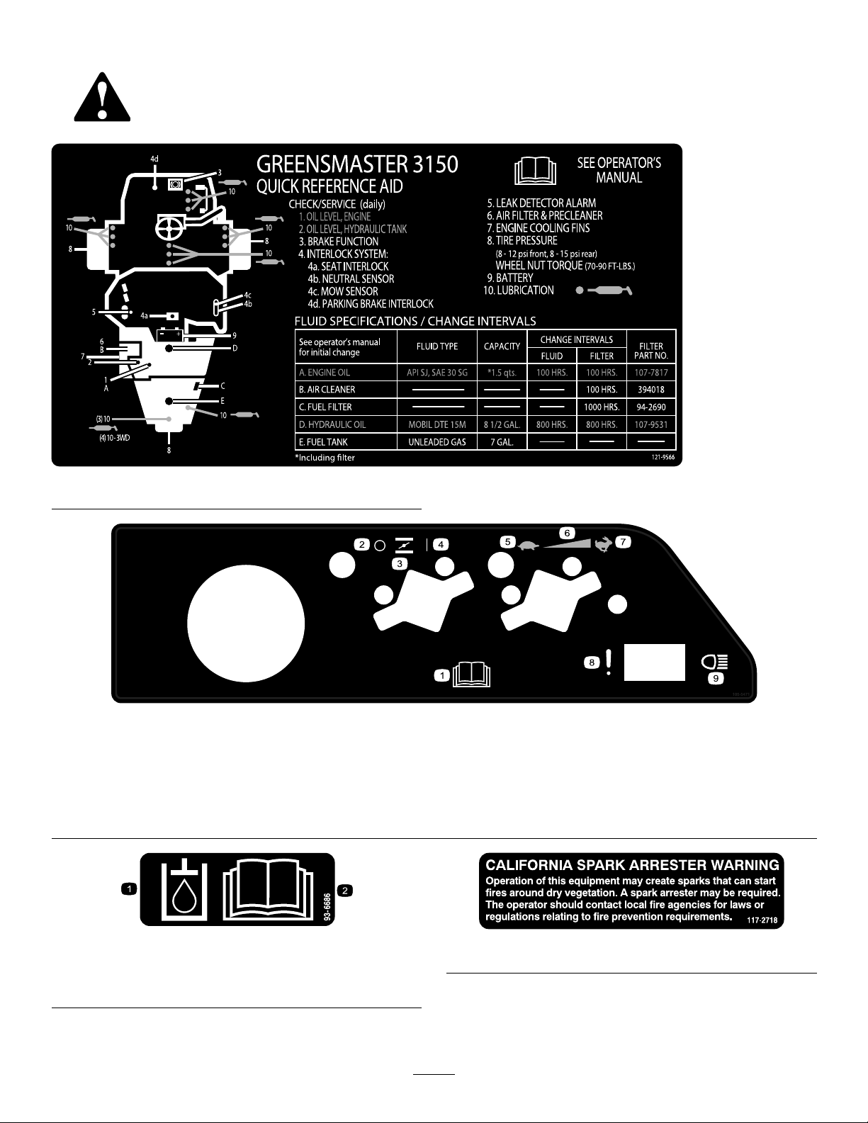
SafetyandInstructionalDecals
Safetydecalsandinstructionsareeasilyvisibletotheoperatorandarelocatednearanyareaofpotential
danger.Replaceanydecalthatisdamagedorlost.
121–9566
105–5471
1.ReadtheOperator'sManual.6.Continuousvariablesetting
2.Off
3.Choke8.Failure/malfunction(Lealdetectoralarmtest)
4.On
5.Slow
7.Fast
9.Headlights
1.Hydraulicoil
2.ReadtheOperator'sManual.
93-6686
7
117–2718
Page 8
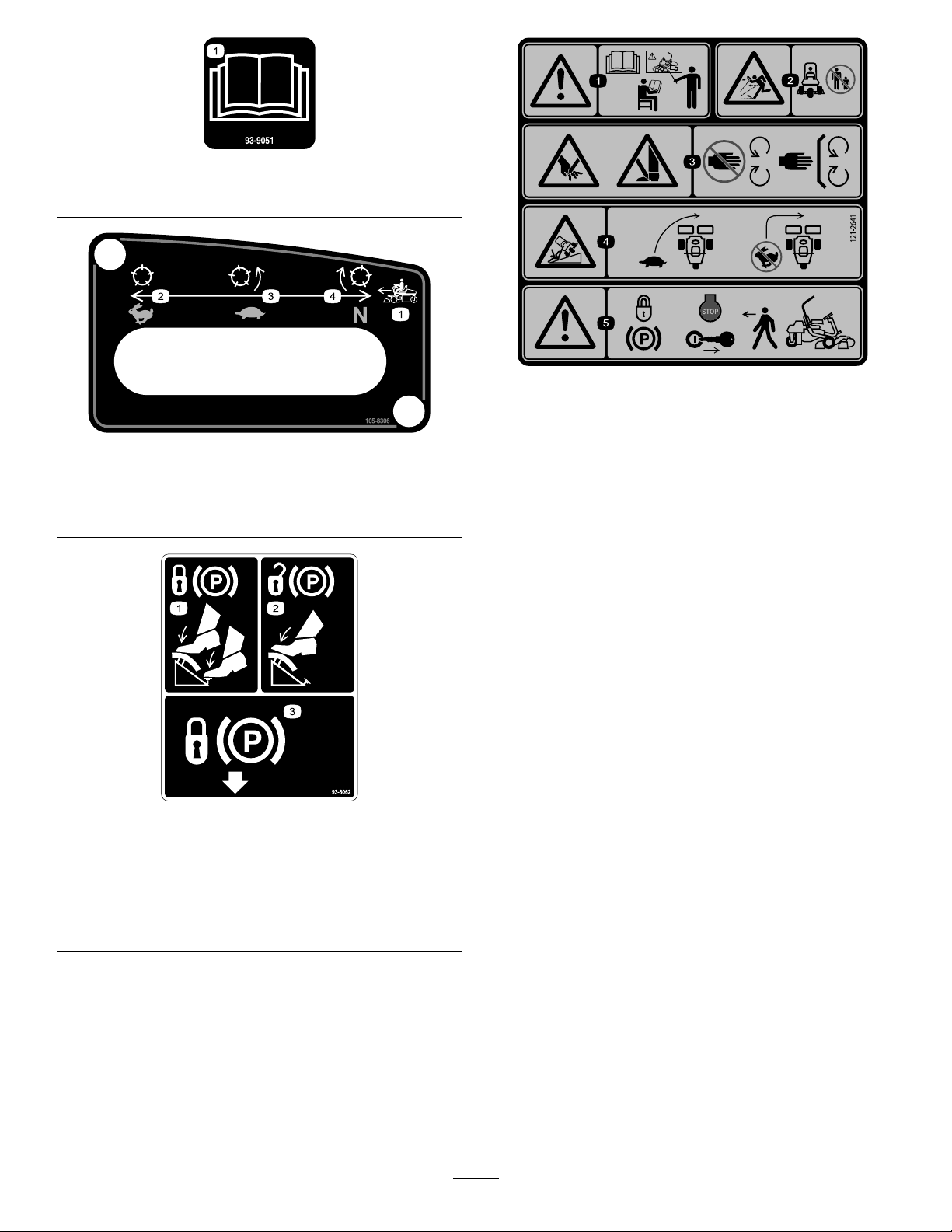
1.ReadtheOperator'sManual.
93–9051
121–2641
105–8306
1.Forwardmachinespeeds
2.Fast-usefortransport4.Neutral-usefor
3.Slow-useformowing
backlapping.
93-8062
1.Tolocktheparkingbrake,
pressthebrakepedaland
theparkingbrakelock.
2.Tounlocktheparking
brake,pressthebrake
pedal.
3.Parkingbrakelock
1.Warning—readthe
Operator’sManual,do
notoperatethismachine
unlessyouaretrained.
2.Thrownobject
hazard—keepbystanders
asafedistancefromthe
machine.
3.Cutting/dismemberment
hazardofhandorfoot,
mowerblade—stayaway
frommovingparts;keep
allguardsandshieldsin
place.
4.Tippinghazard—slow
machinebeforeturning,
donotturnathighspeeds.
5.Warning—locktheparking
brake,stoptheengine
andremovetheignition
keybeforeleavingthe
machine.
8
Page 9
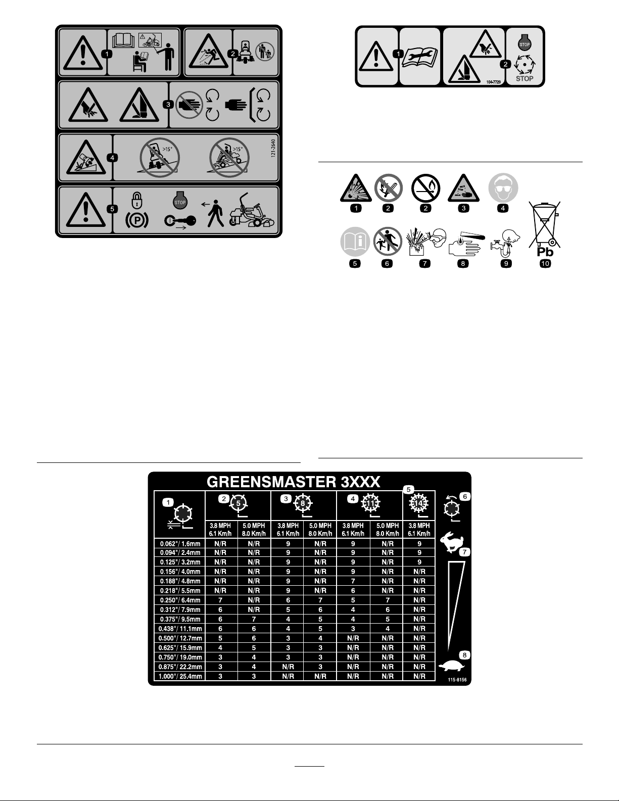
104–7729
Replaces121–2641forCE.
1.Warning—readthe
Operator’sManual,do
notoperatethismachine
unlessyouaretrained.
2.Thrownobject
hazard—keepbystanders
asafedistancefromthe
machine
3.Cutting/dismemberment
hazardofhandorfoot,
mowerblade—stayaway
frommovingparts;keep
allguardsandshieldsin
place.
121–2640
4.Tippinghazard—donot
driveacrossslopesgreater
than15degreesordown
slopesgreaterthan15
degrees.
5.Warning—locktheparking
brake,stoptheengine
andremovetheignition
keybeforeleavingthe
machine.
1.Warning—readthe
instructionsbefore
servicingorperforming
maintenance.
2.Cutting/dismemberment
BatterySymbols
Someorallofthesesymbolsareonyourbattery
1.Explosionhazard
2.Nore,opename,or
smoking.
3.Causticliquid/chemical
burnhazard
4.Weareyeprotection9.Flusheyesimmediately
5.ReadtheOperator's
Manual.
6.Keepbystandersasafe
7.Weareyeprotection;
8.Batteryacidcancause
10.Containslead;donot
hazard;handorfoot—stop
theengineandwaitfor
movingpartstostop.
distancefromthebattery .
explosivegasescan
causeblindnessandother
injuries
blindnessorsevereburns.
withwaterandgetmedical
helpfast.
discard.
115-8156
1.Reelheight3.8Bladecuttingunit5.14Bladecuttingunit7.Fast
2.5Bladecuttingunit4.11Bladecuttingunit6.Reelspeed
9
8.Slow
Page 10
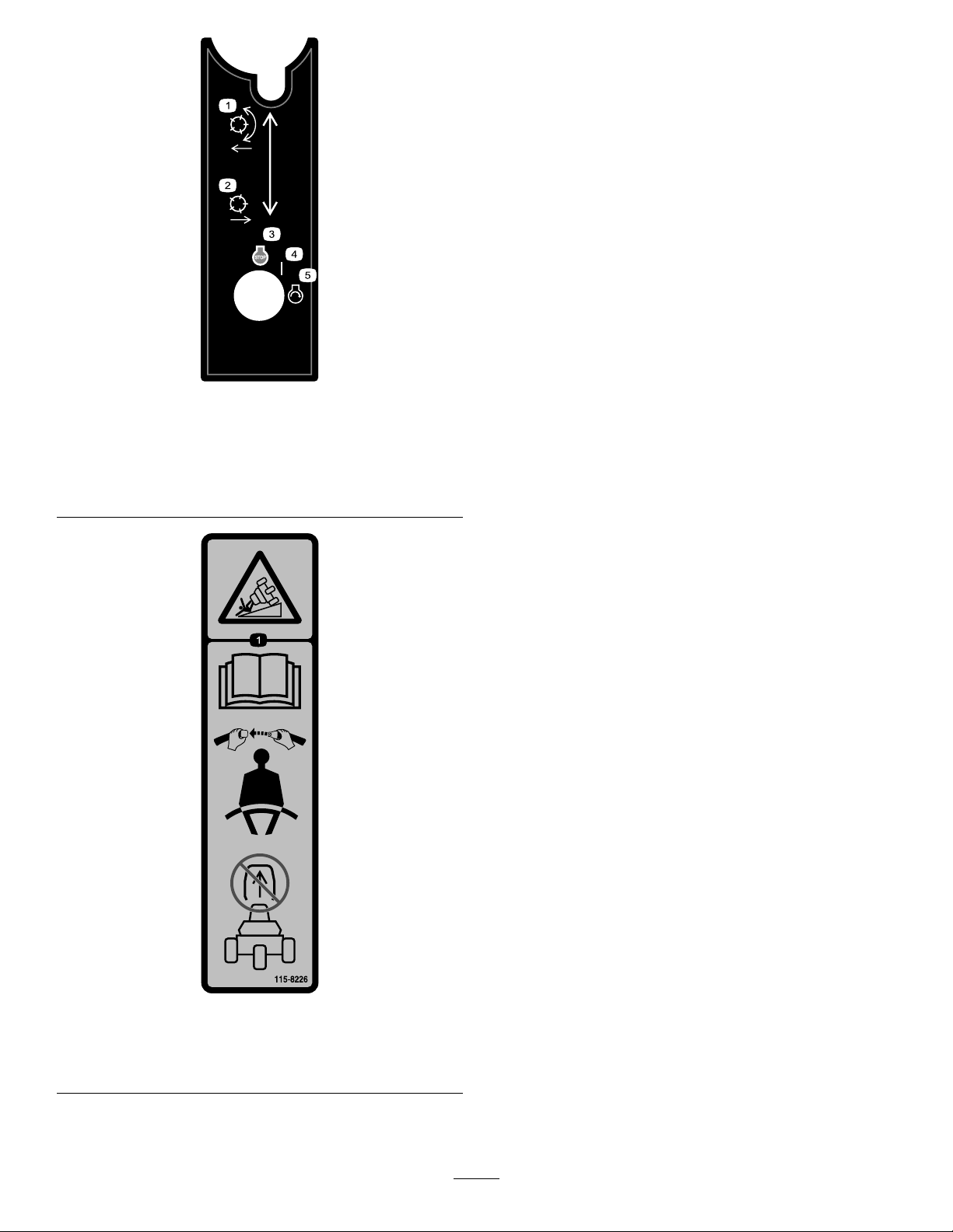
105–8305
1.Lowerandengagethe
reels.
2.Raiseanddisengagethe
reels.
3.Engine-stop
4.On
5.Engine-start
115-8226
1.Tippinghazard—readtheOperator'smanual;alwayswear
aseatbeltwhenoperating,donotremovetherollover
protectionsystem(ROPS).
10
Page 11

Setup
LooseParts
Usethechartbelowtoverifythatallpartshavebeenshipped.
ProcedureDescription
1
2
3
4
5
6
MediaandAdditionalParts
Nopartsrequired
Bolt(1/4x5/8inch)
Nut(1/4inch)
Bolt(1/2x1.75inch)
Nut(1/2inch)
Bolt(#10x5/8inch)
Jamnut(#10)
Cuttingunit
Grassbasket
Rearweightkit,100-6441(purchase
separately)
Calciumchloride(purchaseseparately)
Rearweightkit,99-1645(purchase
separatelyifyouhavea3-wheeldrive
kitinstalled)
Warningdecal(121–2641)
18kg(40
Qty.
lb)
Use
–
2
2
8
8
1
1
3
3
1
1
1
Activateandchargethebattery .
Installthebattery.
Installtherolloverprotectionsystem
(ROPS).
Installthecuttingunits.
Addrearballastandweightkit.
InstallEUdecals,ifrequired.
Description
Operator’sManual
EngineOperator’sManual
OperatorTrainingMaterial
PartsCatalog
Pre-deliveryInspectionSheet
Noiseratingcerticate
CerticateofQuality
DeclarationofConformity
Emissionswarranty1
Ignitionkeys2
Qty.
Use
1
1
1
1
1
1
1
1
Readthisinformationbeforeoperatingthemachine.
Identifyandorderserviceparts.
Readthiscomplianceinformation.
Startthemachine.
11
Page 12
1
ActivatingandChargingthe Battery
NoPartsRequired
Procedure
Useonlyelectrolyte(1.265SpecicGravity)tollbattery
initially.
WARNING
CALIFORNIA
Proposition65Warning
Batteryposts,terminals,andrelated
accessoriescontainleadandleadcompounds,
chemicalsknowntotheStateofCalifornia
tocausecancerandreproductiveharm.
Washhandsafterhandling.
1.Removethewingnuts,washers,andbatteryclampand
liftoutthebattery.
Important:Donotaddelectrolytewhilethe
batteryisinthemachine.Youcouldspillit,
causingcorrosion.
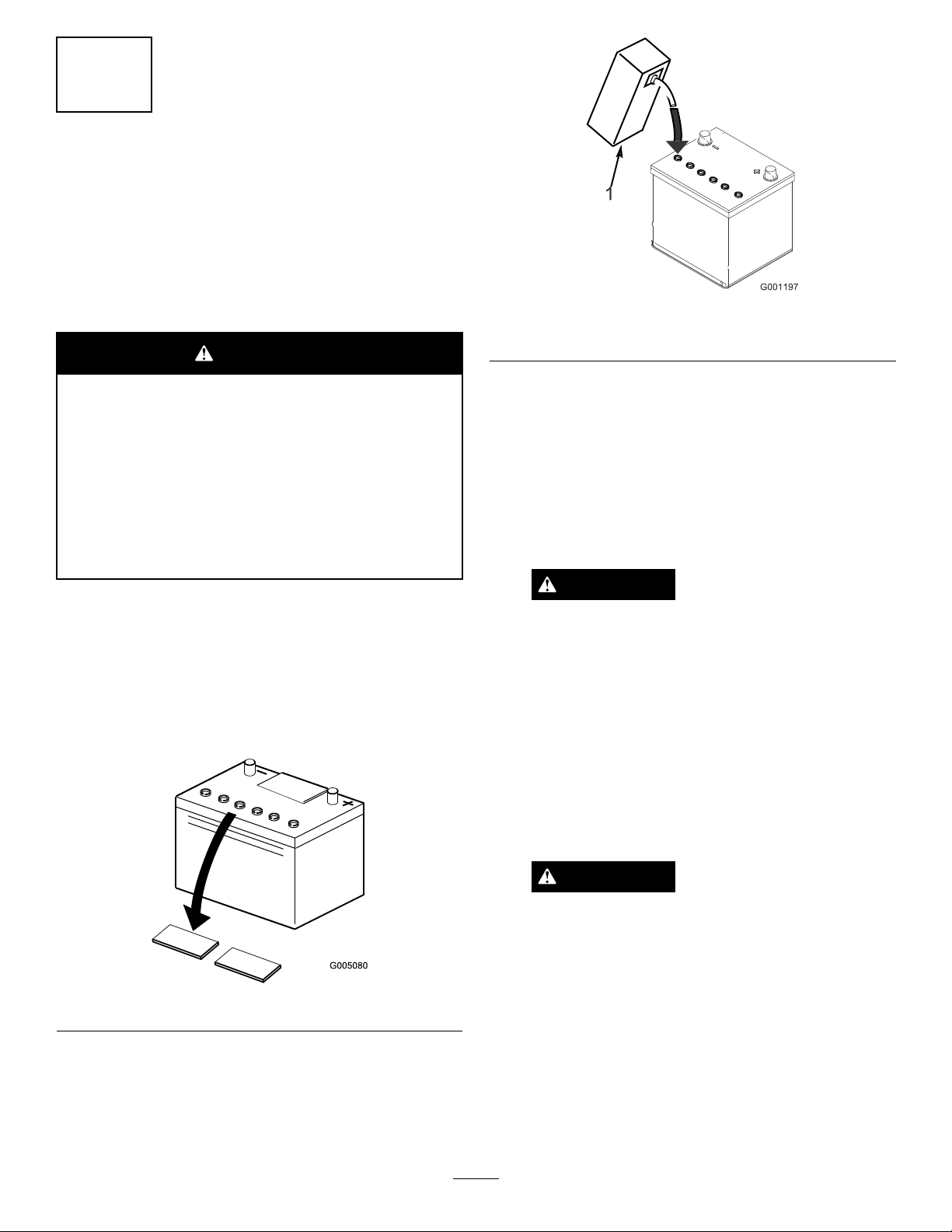
2.Cleanthetopofthebatteryandremovetheventcaps
(Figure3).
Figure4
1.Electrolyte
4.Allowapproximately20to30minutesforthe
electrolytetosoakintotheplates.Fillasnecessaryto
bringtheelectrolytetowithinabout6mm(1/4inch)
ofthebottomofthellwell(Figure4).
5.Connecta2to4ampbatterychargertothebattery
posts.Chargethebatteryfor2hoursat4ampsorfor
4hoursat2ampsuntilthespecicgravityis1.250or
higherandthetemperatureisatleast16°C(60°F)
withallcellsgassingfreely .
WARNING
Chargingthebatteryproducesgassesthatcan
explode.
Neversmokenearthebatteryandkeepsparks
andamesawayfrombattery.
6.Whenthebatteryischarged,disconnectthecharger
fromtheelectricaloutletandbatteryposts.
Figure3
3.Carefullylleachcellwithelectrolyteuntiltheplates
arecoveredwithabout6mm(1/4inch)ofuid
(Figure4).
Note:Afterthebatteryhasbeenactivated,add
onlydistilledwatertoreplacenormalloss,although
maintenance-freebatteriesshouldnotrequirewater
undernormaloperatingconditions.
WARNING
Batteryterminalsormetaltoolscouldshort
againstmetaltractorcomponentscausing
sparks.Sparkscancausethebatterygassesto
explode,resultinginpersonalinjury.
•Whenremovingorinstallingthebattery,
donotallowthebatteryterminalstotouch
anymetalpartsofthetractor.
•Donotallowmetaltoolstoshortbetween
thebatteryterminalsandmetalpartsof
thetractor.
12
Page 13

WARNING
Failuretocorrectlyactivatethebatterymay
resultinbatterygassingand/orpremature
batteryfailure.
7.Installtheventcaps.
2
InstallingtheBattery
Partsneededforthisprocedure:
2
Bolt(1/4x5/8inch)
2
Nut(1/4inch)
Procedure
1.Mountthebatterywiththebatteryterminalstoward
thefrontofthemachine.
2.Connectthepositivebatterycable(red)fromthe
startersolenoidtothepositivepost(+)ofthebattery
(Figure5).Secureitwithawrenchandcoatthe
terminalwithpetroleumjelly.Makesurethecablewill
cleartheseat,intherear-mostposition,whichcould
causewearordamagetothecable.
WARNING
Batteryterminalsormetaltoolscouldshort
againstmetaltractorcomponentscausing
sparks.Sparkscancausethebatterygassesto
explode,resultinginpersonalinjury.
•Whenremovingorinstallingthebattery,
donotallowthebatteryterminalstotouch
anymetalpartsofthetractor.
Figure5
1.Negative(-)2.Positive(+)
3.Connecttheblackgroundcable(fromtheenginebase)
tothenegative(-)postofthebattery.Secureitwitha
wrenchandcoattheterminalwithpetroleumjelly .
WARNING
Incorrectbatterycableroutingcoulddamage
thetractorandcablescausingsparks.Sparks
cancausethebatterygassestoexplode,
resultinginpersonalinjury.
•Alwaysdisconnectthenegative(black)
batterycablebeforedisconnectingthe
positive(red)cable.
•Alwaysconnectthepositive(red)battery
cablebeforeconnectingthenegative
(black)cable.
4.Installthebatteryclampandwashersandsecurethem
withthewingnuts.
5.Placetheterminalcoveroverthepositive(+)battery
post.
•Donotallowmetaltoolstoshortbetween
thebatteryterminalsandmetalpartsof
thetractor.
3
InstallingtheRollOver ProtectionSystem(ROPS)
Partsneededforthisprocedure:
8
Bolt(1/2x1.75inch)
8
Nut(1/2inch)
Procedure
1.Removethescrewsandnutssupportingthejackpad
ontherightsideofthemachine.
13
Page 14
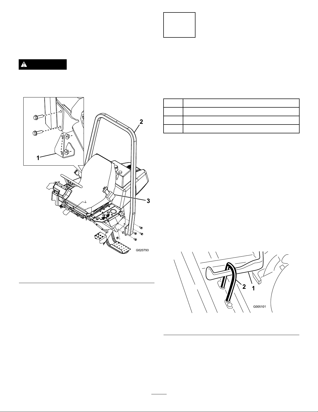
2.LowertheROPSframe(Figure6)ontothemounting
3
G020793
brackets,aligningthemountingholes.
3.Secureeachsideoftherollbarandthepreviously
removedjackpadtothemountingbracketswith8
screws(1/2-13x1.75inch)andlocknuts.Torquethe
fastenersto91to115N-m(67to85ft-lb).
WARNING
TheRolloverProtectionSystem(ROPS)isan
integralandeffectivesafetydevice.Alwaysusethe
seatbeltwiththerollbar.
4
InstallingtheCuttingUnits
(Forcuttingunitmodels04610,
04611,04616,04618,04619,
and04624only)
Partsneededforthisprocedure:
1
Bolt(#10x5/8inch)
1
Jamnut(#10)
3
Cuttingunit
3
Grassbasket
Procedure
Important:Don’traisethesuspensiontothetransport
positionwhenthereelmotorsareintheholdersonthe
machineframe.Damagetothemotorsorhosescould
result.
1.Jackpad
2.ROPS
Note:Whensharpening,settingtheheight-of-cutor
performingothermaintenanceproceduresonthecutting
units,storethecuttingunitreelmotorsinthesupporttubes
onthefrontoftheframetopreventdamagetothehoses.
1.Removethecuttingunitsfromthecartons.Assemble
andadjustthemaslistedinthecuttingunitOperator's
Manual.
2.Slidethecuttingunitunderthepullframewhile
hookingthelifthookontotheliftarm(Figure7).
Figure6
3.Seatbelt
Figure7
1.Liftarm2.Lifthook
3.Slidethesleevebackontheballjointreceiverandhook
thereceiverontothecuttingunitballstud.Releasethe
14
sleevesoitslidesoverthestudandlockstheassemblies
together(
Figure8).
Page 15
G020794
1.Pullframe
G020795
2.Pullarm
Figure8
3.Ballstud
Figure10
1.Mountingbolts2.Drivemotor
4.Mountthebasketsonthepullframes,loosenthe
jamnutsonthepullarms,andadjusttheballsockets
untilthereis6to13mm(1/4to1/2inch)clearance
betweenthelipofthebasketandthereelbladesorthe
frontshield.
Note:Thispreventsthebasketfromtippingthe
cuttingunitforward,causingtheliftrollertocomeoff
oftheliftarmwhileinthemowingoperation.
Besurethebasketlipisequidistantfromthereelblades
allacrosseachreel.Ifthebasketistooclosetothereel,
itispossibleforthereeltocontactthebasketwhenthe
cuttingunitisraisedoffoftheground.
5.Alignthesocketsintheballjointssotheopensideof
thesocketiscenteredtowardstheballstud.Tightenthe
jamnutstosecurethesocketsinposition(Figure9).
7.Coatthesplineshaftofthemotorwithcleangrease
andinstallthemotorbyrotatingthemotorclockwise
sothatthemotorangesclearthestuds.Rotatethe
motorcounterclockwiseuntiltheangesareencircling
thestuds.
8.Tightenthemountingbolts(Figure10).
5
AddingRearBallastand WeightKit
Partsneededforthisprocedure:
1
Rearweightkit,100-6441(purchaseseparately)
18kg
(40lb)
Calciumchloride(purchaseseparately)
Rearweightkit,99-1645(purchaseseparatelyifyou
1
havea3-wheeldrivekitinstalled)
Figure9
1.Pullarm3.Balljoint
2.Jamnut
6.Ensurethatthereisapproximately13mm(1/2inch)
ofthreadsexposedoneachreeldrivemotormounting
bolt(Figure10).
Procedure
ThisunitcomplieswiththeANSIB71.4-2004andEN836
Standardswhenyouequipitwithrearweightkit100-6441
and18kg(40lb)ofcalciumchlorideballastisaddedtothe
rearwheel.Ifyouinstalla3-WheelDrivekit,userearweight
kit99-1645insteadof100-6441.
Important:Ifapunctureoccursinatirewithcalcium
chloride,removetheunitfromtheturfareaasquickly
aspossible.Topreventpossibledamagetotheturf,
immediatelysoaktheaffectedareawithwater.
15
Page 16

ProductOverview
6
InstallingCEDecals
Partsneededforthisprocedure:
1
Warningdecal(121–2641)
Procedure
IfthismachinewillbeusedintheEU,afxthewarningdecal
121–2641overwarningdecal(121–2640).
Controls
BrakePedal
Thebrakepedal(Figure11)actuatesanautomotivedrum-type
mechanicalbrakelocatedateachtractionwheel.
ParkingBrakeButton
Pressingthebrakepedaltoactuatethebrakeassembly,then
pressingthesmallbuttonindicated(Figure11)willkeepthe
brakesactuatedforparking.Disengageitbypressingthe
brakepedal.Locktheparkingbrakebeforeyouleavethe
machine.
Figure11
1.Tractionpedal3.Parkingbrakebutton
2.Brakepedal
TractionandStoppingPedal
Thetractionpedal(Figure11)hasthreefunctions:tomake
themachinemoveforward,tomoveitbackward,andtostop
themachine.Pressthetopofthepedaltomoveforward
andthebottomofthepedaltomovebackwardortoassist
instoppingwhenmovingforward.Also,allowthepedal
tomovetotheneutralpositiontostopthemachine.For
operatorcomfort,donotresttheheelofyourfootonreverse
whenoperatingforward(Figure12).
Figure12
16
Page 17

ThrottleControl
Thethrottlecontrol(Figure13)givestheoperatortheability
tocontrolthespeedoftheengine.Movingthethrottle
controltowardtheFastpositionincreasestheenginerpm;
movingthethrottlecontroltowardSlowwilldecreasethe
enginerpm.
Note:Theenginecannotbestoppedbytheuseofthe
throttlecontrol.
Figure13
1.Throttlecontrol
2.Chokecontrol
3.Leakdetectortest/light
switch
Figure14
1.Seatadjustmentlever
Raise/LowerMowControl
Movingthecontrol(Figure15)forwardduringoperation
lowersthecuttingunitsandstartsthereels.Pullbackonthe
controltostopthereelsandraisethecuttingunits.During
operationthereelscanbestoppedbypullingbackonthe
controlmomentarilyandreleasingit.Restartthereelsby
movingthecontrolforward.
Choke
Tostartacoldengine,closethecarburetorchokebymoving
thechokecontrol(
Aftertheenginestarts,regulatethechoketokeeptheengine
runningsmoothly.Assoonaspossible,openthechokeby
pullingitrearwardtotheOpenposition.Awarmengine
requireslittleornochoking.
Figure13)forwardtotheClosedposition.
Leakdetectortest/lightswitch
Fromthemiddleoperatingposition,movetheswitch
(Figure13)rearwardtochecktheoperationoftheleak
detectoralarmandtimedelay.Movetheswitchforwardto
operatetheoptionallights.
HourMeter
Thehourmeter(locatedontheleftcontrolpanel)indicates
thetotalhoursthemachinehasoperated.Itstartstofunction
wheneverthekeyswitchisrotatedtoOn.
SeatAdjustingLever
Figure15
1.Functionalcontrollever
2.Ignitionswitch
3.Raise/lowermowcontrol
FunctionalControlLever
Thefunctionalcontrollever(Figure15)providestwotraction
selectionsplusaNeutralposition.Itispermissibletoshift
frommowtotransportortransporttomow(nottoneutral)
whilethemachineisinmotion.Nodamagewillresult.
•RearPosition-neutralandbacklapping
•MiddlePosition-usedformowingoperation
•FrontPosition-usedfortransportoperation
Thislever,ontheleftsideoftheseat(Figure14),allowsa10
cm(4inch)foreandaftadjustmentoftheseat.
IgnitionSwitch
Insertthekeyintotheswitch(Figure15)andturnitclockwise
asfaraspossibletotheStartpositiontostarttheengine.
Releasethekeyassoonastheenginestarts;thekeywillmove
totheOnposition.TurnthekeycounterclockwisetotheOff
positiontostoptheengine.
17
Page 18

SteeringWheelLockingLever
Rotatethelever(Figure16)forwardtoloosentheadjustment,
raiseorlowersteeringwheelforoperatorcomfort,then,
rotatetheleverrearwardtotightentheadjustment.
Figure16
1.Steeringwheellockinglever
SteeringArmLockingKnob
Loosenknob(Figure17)untilshoulderonknobclearsthe
notchesinsteeringarm.Raiseorlowersteeringarmto
desiredheightwhilealigningshoulderofknobwithnotchin
steeringarm.Tightenknobtolockadjustment.
Figure18
1.Fuelshut-off(underthefueltank)
BacklapLever
Usethebacklaplever(Figure19)inconjunctionwiththe
lowermow/raisecontrolleverforbacklappingthereels.
Figure19
Figure17
1.Steeringarmlockingknob
FuelShut-OffValve
Closethefuelshut-offvalve(Figure18),underthefueltank,
whenstoringortransportingthemachineonatruckortrailer.
1.Backlaplever2.Reelspeedcontrol
ReelSpeedControl
Usethereelspeedcontrol(Figure19)toadjusttherpmof
thereel.
18
Page 19

Specications
G017134
1
2
Note:Specicationsanddesignaresubjecttochange
withoutnotice.
OverallWidthw/reels177cm(69–3/4inches)
OverallLength228.6cm(90inches)
OverallHeight189cm(74-1/2inches)
OverallWeightw/1 1–blade
cuttingunits
NetWeight(dry)493kg(1,087lb)
WidthofCut149.9cm(59inches)
583kg(1,374lb)
Operation
Note:Determinetheleftandrightsidesofthemachine
fromthenormaloperatingposition.
ThinkSafetyFirst
Pleasecarefullyreadallofthesafetyinstructionsandsymbols
inthesafetysection.Knowingthisinformationcouldhelp
youorbystandersavoidinjury.
Theuseofprotectiveequipment,suchasbutnotlimitedto,
foreyes,ears,feet,andheadisrecommended.
WheelTread
WheelBase
MowSpeed(adjustable)3.2–8km/h(2–5mph)
TransportSpeed12.9km/h(8.0mph)
ReverseSpeed4km/h(2.5mph)
ReelSpeed(at2,850RPM
enginespeed)
125.7cm(49-1/2inches)
119.1cm(46-7/8inches)
approximately
approximately
1,845rpmapproximately
Attachments/Accessories
AselectionofToroapprovedattachmentsandaccessoriesis
availableforusewiththemachinetoenhanceandexpand
itscapabilities.ContactyourAuthorizedServiceDealeror
Distributororgotowww .T oro.comforalistofallapproved
attachmentsandaccessories.
CAUTION
Useyourseatbeltwhileoperatingthismachine.
CheckingtheEngineOil
Theengineisshippedwith1.4liters(1.5quarts)(w/lter)of
oilinthecrankcase;however,theoillevelmustbechecked
beforeandaftertheengineisrststarted.
Theengineusesanyhigh-qualitydetergentoilhavingthe
AmericanPetroleumInstitute(API)serviceclassicationof
SG,SH,orSJorhigher.Therecommendedviscosity(weight)
isSAE30.
1.Positionthemachineonalevelsurface.
2.Pullthedipstickoutandwipeitwithacleanrag.Push
thedipstickintothetubeandmakesureitisseated
fully(
Figure20).
Figure20
1.Dipstick2.Fillercap
3.Pullthedipstickoutofthetubeandchecktheoillevel.
4.Iftheoillevelislow,removethellercapfromthe
valvecoverandpouroilintotheopeninginthevalve
coveruntiltheoillevelisuptotheFullmarkonthe
dipstick.Addtheoilslowlyandchecktheleveloften
duringthisprocess.Donotoverll.
Important:Checktheoillevelevery8operating
hoursordaily.
19
Page 20

5.Installthellercapanddipstickrmlyinplace.
FillingtheFuelTank
Useunleadedregulargasolinesuitableforautomotiveuse
(87pumpoctaneminimum).Leadedregulargasolinemaybe
usedifunleadedregularisnotavailable.
Important:Neverusemethanol,gasolinecontaining
methanol,orgasoholcontainingmorethan10%ethanol
becausethefuelsystemcouldbedamaged.Donotmix
oilwithgasoline.
DANGER
Incertainconditions,gasolineisextremely
ammableandhighlyexplosive.Areorexplosion
fromgasolinecanburnyouandothersandcan
damageproperty.
•Fillthefueltankoutdoors,inanopenarea,
whentheengineiscold.Wipeupanygasoline
thatspills.
•Neverllthefueltankinsideanenclosedtrailer.
•Donotllthefueltankcompletelyfull.Add
gasolinetothefueltankuntilthelevelis1inch
(25mm)belowthebottomofthellerneck.
Thisemptyspaceinthetankallowsgasolineto
expand.
DANGER
Incertainconditionsduringfueling,static
electricitycanbereleasedcausingasparkwhich
canignitethegasolinevapors.Areorexplosion
fromgasolinecanburnyouandothersandcan
damageproperty.
•Alwaysplacegasolinecontainersontheground
awayfromyourvehiclebeforelling.
•Donotllgasolinecontainersinsideavehicleor
onatruckortrailerbedbecauseinteriorcarpets
orplastictruckbedlinersmayinsulatethe
containerandslowthelossofanystaticcharge.
•Whenpractical,removegas-poweredequipment
fromthetruckortrailerandrefueltheequipment
withitswheelsontheground.
•Ifthisisnotpossible,thenrefuelsuch
equipmentonatruckortrailerfromaportable
container,ratherthanfromagasolinedispenser
nozzle.
•Ifagasolinedispensernozzlemustbeused,
keepthenozzleincontactwiththerimofthe
fueltankorcontaineropeningatalltimesuntil
fuelingiscomplete.
1.Cleanaroundthefueltankcapandremoveit
(Figure21).
•Neversmokewhenhandlinggasoline,andstay
awayfromanopenameorwheregasoline
fumesmaybeignitedbyaspark.
•Storegasolineinanapprovedcontainerand
keepitoutofthereachofchildren.Neverbuy
morethana30-daysupplyofgasoline.
•Donotoperatewithoutentireexhaustsystemin
placeandinproperworkingcondition.
Figure21
1.Fueltankcap
2.Addunleadedregulargasolinetothefueltankuntilthe
levelis25mm(1inch)belowthebottomoftheller
neck.
Thisspaceinthetankallowsgasolinetoexpand.Do
notllthefueltankcompletelyfull.
Note:Fueltankcapacityis26.6liters(7U.S.gallons)
3.Installthefueltankcapsecurely.Wipeupanygasoline
thatmayhavespilled.
CheckingtheHydraulicFluid Level
Thehydraulicuidreservoirislledatthefactorywith
approximately32.2l(8.5U .S.gallons)ofhighqualityhydraulic
20
Page 21

uid.Checkthelevelofthehydraulicuidbeforethe
G017136
1
2
engineisrststartedanddailythereafter.Therecommended
replacementuidisasfollows:
ToroPremiumAllSeasonHydraulicFluid(Availablein5
gallonpailsor55gallondrums.SeepartscatalogorT oro
distributorforpartnumbers.)
Alternateuids:IftheTorouidisnotavailable,otheruids
maybeusedprovidedtheymeetallthefollowingmaterial
propertiesandindustryspecications.Wedonotrecommend
theuseofsyntheticuid.Consultwithyourlubricant
distributortoidentifyasatisfactoryproduct
Note:Torowillnotassumeresponsibilityfordamage
causedbyimpropersubstitutions,souseonlyproducts
fromreputablemanufacturerswhowillstandbehindtheir
recommendation.
HighViscosityIndex/LowPourPointAnti-wearHydraulic
Fluid,ISOVG46
MaterialProperties:
Viscosity,ASTMD445cSt@40°C44to48
ViscosityIndexASTM
D2270
PourPoint,ASTMD97-34°Fto-49°F
IndustrySpecications:
VickersI-286-S(QualityLevel),VickersM-2950-S
(QualityLevel),DenisonHF-0
cSt@100°C7.9to8.5
140to160
29°C(85°F)shouldhaveOilCoolerKit,PartNo.
105-8339,installed.
1.Positionthemachineonalevelsurface.Makesurethe
machinehascooleddownsotheoiliscold.Check
theoillevelbyviewingthesightwindowontheside
oftheauxiliaryoiltank(
Figure22).Iftheoillevelis
betweenthetwomarksonthesightwindow,theoil
levelissufcient.
2.Iftheoillevelisbelowthebottommarkinthesight
window,removethecapfromthehydraulicoiltank
andslowlyllthetankwiththeappropriatehighquality
hydraulicuiduntilthelevelisbetweenthetwomarks
onthesightwindow.Donotmixoils.Installthecap.
Important:Topreventsystemcontamination,
cleanthetopofthehydraulicoilcontainersbefore
puncturingthem.Ensurethatthepourspoutand
funnelareclean.
Note:Makeaclosevisualinspectionofthehydraulic
components.Inspectthemforleaks,loosefasteners,
missingparts,improperlyroutedlines,etc.Makeany
correctionsnecessary.
Important:TheISOVG46Multigradeuidhasbeen
foundtoofferoptimalperformanceinawiderangeof
temperatureconditions.Foroperationinconsistently
highambienttemperatures,18°C(65°F)to49°C
(120°F),ISOVG68hydraulicuidmayofferimproved
performance.
PremiumBiodegradableHydraulicFluid-MobilEAL
EnviroSyn46H
Important:MobilEALEnviroSyn46Histheonly
syntheticbiodegradableuidapprovedbyToro.This
uidiscompatiblewiththeelastomersusedinToro
hydraulicsystemsandissuitableforawide-range
oftemperatureconditions.Thisuidiscompatible
withconventionalmineraloils,butformaximum
biodegradabilityandperformancethehydraulicsystem
shouldbethoroughlyushedofconventionaluid.The
oilisavailablein19l(5gallon)containersor55gallon
drumsfromyourMobilDistributor.
Note:Manyhydraulicuidsarealmostcolorless,makingit
difculttospotleaks.Areddyeadditiveforthehydraulic
systemoilisavailablein20ml(2/3oz)bottles.Onebottle
issufcientfor15-221(4-6gallons)ofhydraulicoil.Order
partno.44-2500fromyourauthorizedTorodistributor.This
reddyeisnotrecommendedforusewithbiodegradable
uids.Usefoodcoloring.
Figure22
1.Sightwindow
2.Hydraulictankcap
CheckingtheTirePressure
Thetiresareover-inatedatthefactoryforshipping
purposes.Reducethepressuretotheproperlevelsbefore
startingtheunit.
Varythetirepressureforthefrontwheels,depending
uponyourturfconditions,fromaminimumof55kPatoa
maximumof83kPa(8to12psi).
Varythetirepressurefortherearwheelfromaminimumof
55kPatoamaximumof103kPa(8to15psi).
Important:Regardlessofthehydraulicuidtype
used,anytractionunitusedforoffgreenapplications,
verticuttingorusedduringambienttemperaturesabove
21
Page 22

CheckingtheTorqueofthe
StartingtheEngine
WheelNuts
WARNING
Failuretomaintainpropertorqueofthewheelnuts
couldresultinpersonalinjury.
Torquethewheelnutsto95to122N-m(70-90ft-lb)
after1-4hoursofoperationandagainafter10hours
ofoperation.Torqueevery200hoursthereafter.
Break-inPeriod
RefertotheEngineManualsuppliedwiththemachineforoil
changeandmaintenanceproceduresrecommendedduring
thebreak-inperiod.
Only8hoursofmowingoperationisrequiredforthebreak-in
period.
Sincethersthoursofoperationarecriticaltofuture
dependabilityofthemachine,monitoritsfunctionsand
performancecloselysothatminordifculties,whichcould
leadtomajorproblems,arenotedandcanbecorrected.
Inspectthemachinefrequentlyduringbreak-inforsignsof
oilleakage,loosefasteners,oranyothermalfunction.
Toensureoptimumperformanceofthebrakesystem,burnish
(break-in)thebrakesbeforeusingthemachine.Toburnish
thebrakes,rmlyapplythebrakesanddrivethemachineat
mowingspeeduntilthebrakesarehot,asindicatedbytheir
smell.Anadjustmenttothebrakesmayberequiredafter
break-in;refertoAdjustingtheBrakes(page38).
Note:Inspecttheareabeneaththemowerstobecertain
theyareclearofdebris.
1.Sitontheseat,locktheparkingbrake,disengagethe
raise/lowermowcontrolandmovethefunctional
controllevertoNeutral.
2.Removeyourfootfromthetractionpedalandmake
surethepedalisintheNeutralposition.
3.Movethechokelevertotheclosedposition(onlywhen
startingacoldengine)andthethrottlelevertothehalf
throttleposition.
4.Insertandrotatetheignitionkeyclockwiseuntilthe
enginestarts.Aftertheenginestarts,regulatethe
choketokeeptheenginerunningsmoothly.Assoon
aspossible,openthechokebypullingitrearwardto
theOffposition.Awarmenginerequireslittleorno
choking.
5.Checkthemachineoutwiththefollowingprocedures
aftertheenginehasstarted:
A.MovethethrottlecontroltotheFastposition
andmomentarilyengagethereelsbymoving
theraise/lowermowcontrolleverforward.The
cuttingunitsshoulddropandallthereelsshould
turn.
B.Movetheraise/lowermowcontrolleverrearward.
Thecuttingreelsshouldstopandthecuttingunits
shouldraisetothefulltransportposition.
Important:Stoptheengine.Checkthelipof
eachbaskettobesureitisnotincontactwith
thereelduringoperation.Adjustthe
pullarmsifcontactisnoted;referto
4InstallingtheCuttingUnits(Forcuttingunitmodels04610,04611,04616,04618,04619,and04624only)(page14).
C.Depressthebrakepedaltokeepthemachinefrom
moving,andoperatethetractionpedalthrough
theforwardandreversepositions.
D.Continuetheaboveprocedurefor1-2minutes.
Neutralizethefunctionalcontrollever,lockthe
parkingbrake,andturntheengineoff.
E.Checkforoilleaks.Ifoilleaksappear,check
thetightnessofthehydraulicttings.Ifoil
leakscontinuetoappear,contactyourlocal
ToroDistributorforassistanceand,ifnecessary,
replacementparts.
Important:Atraceofoilonthemotoror
wheelsealsisnormal.Sealsrequireasmall
amountoflubricationtoperformproperly.
Note:Sincethemachineisnewandthebearings
andreelsaretight,itisnecessarytousetheFast
throttlecontrolpositionforthischeck.Afast
throttlesettingmaynotberequiredafterthe
break-inperiod.
22
Page 23

CheckingtheSafetyInterlock System
CAUTION
Ifthesafetyinterlockswitchesaredisconnectedor
damagedthemachinecouldoperateunexpectedly
causingpersonalinjury.
•Donottamperwiththeinterlockswitches.
•Checktheoperationoftheinterlockswitches
dailyandreplaceanydamagedswitchesbefore
operatingthemachine.
engagetheparkingbrake.Starttheengine.Release
theparkingbrake,movethefunctionalcontrollever
tomow ,andrisefromtheseat.Theengineshould
kill,whichmeansthattheinterlocksystemisoperating
correctly.Correcttheproblemifitisnotoperating
properly.
5.Sitontheseat,movethetractionpedaltoNeutral,
movethefunctionalcontrollevertoNeutral,and
engagetheparkingbrake.Starttheengine.Movethe
raise/lowermowcontrolforwardtolowerthecutting
units.Thecuttingunitsshouldnotstartrotating.If
theydo,theinterlocksystemisnotoperatingcorrectly.
Correcttheproblem.
Thepurposeofthesafetyinterlocksystemistoprevent
operationofthemachinewherethereispossibleinjuryto
theoperatororthemachine.
Thesafetyinterlocksystempreventstheenginefromstarting
unless:
•Thetractionpedalisinneutral.
•Thefunctionalcontrolleverisinneutral.
Thesafetyinterlocksystempreventsthemachinefrom
movingunless:
•Theparkingbrakeisoff.
•Theoperatorisseated.
•ThefunctionalcontrolleverisinMoworTransport.
Thesafetyinterlocksystempreventsthereelsfromoperating
unlessthefunctionalcontrolleverisintheMowposition.
Performthefollowingsystemchecksdailytobesurethe
interlocksystemisoperatingcorrectly:
1.Sitontheseat,movethetractionpedaltoNeutral,
movethefunctionalcontrollevertoNeutral,and
engagetheparkingbrake.Trytodepressthetraction
pedal.Thepedalshouldnotdepress,whichmeansthat
theinterlocksystemisoperatingcorrectly.Correctthe
problemifitisnotoperatingproperly.
2.Sitontheseat,movethetractionpedaltoNeutral,
movethefunctionalcontrollevertoNeutral,and
engagetheparkingbrake.Movethefunctionalcontrol
levertomowortransportandtrytostarttheengine.
Theengineshouldnotcrank,whichmeansthatthe
interlocksystemisoperatingcorrectly.Correctthe
problemifitisnotoperatingproperly.
3.Sitontheseat,movethetractionpedaltoNeutral,
movethefunctionalcontrollevertoNeutral,and
engagetheparkingbrake.Starttheengineandmove
thefunctionalcontrollevertomowortransport.The
engineshouldkill,whichmeansthattheinterlock
systemisoperatingcorrectly.Correcttheproblemifit
isnotoperatingproperly .
CheckingtheLeakDetector
Theleakdetectorsystemisdesignedtoassistinearly
detectionofhydraulicoilsystemleaks.Iftheoillevelinthe
mainhydraulicreservoir,isloweredby118-177ml(4to6
ounces),theoatswitchinthetankwillclose.Afteraone
seconddelay,thealarmwillsound,alertingtheoperator
(Figure25).Expansionofoil,duetonormalheatingduring
machineoperation,willcausetheoiltotransferintothe
auxiliaryoilreservoir.Theoilisallowedtoreturntothemain
tankwhentheignitionswitchisturnedoff.
Figure23
BeforeStarting(oilcold)
1.Fillercap
2.Fillerneck6.Floatraisedswitchopen
3.Overowtube
4.Sightwindow8.Fluidlevel(cold)
5.Solenoidreturnvalveopen
7.Nosound
4.Sitontheseat,movethetractionpedaltoNeutral,
movethefunctionalcontrollevertoNeutral,and
23
Page 24

Figure24
NormalOperation(oilwarm)
3.Insertacleanrodorscrewdriverintothetankneckand
gentlypushdownontheswitchoat(Figure26).The
alarmshouldsoundaftertheone-seconddelay.
1.Solenoidreturnvalve
closed
2.Floatraisedswitchopen
LeakAlert!
1.Floatdownswitchclosed
Fluidleveldown118–177
ml(4to6ounces)
2.Warningbuzzer
3.Warningbuzzer
4.Fluidlevel(warm)
Figure25
3.Fluidlevel(warm)
CheckingtheSystemOperation
1.WithignitionswitchintheOnposition,movethe
leakdetectorswitchrearwardandhold.Afterthe
one-secondtimedelayelapsesthealarmshouldsound.
2.Releasetheleakdetectorswitch.
Figure26
1.Cleanrodorscrewdriver
2.Pressdownonswitch
3.Warningbuzzer
4.Releasetheoat.Thealarmshouldstopsounding.
5.Installthestrainerscreenandhydraulictankcap.Move
theignitionswitchtotheOffposition.
SettingtheReelSpeed
Toachieveaconsistent,highquality-of-cutandauniform
aftercutappearance,itisimportantthatthereelspeedcontrol
(locatedonthemanifoldblockunderseat)becorrectlyset.
Adjustthereelspeedcontrolasfollows:
1.Selecttheheight-of-cutatwhichthecuttingunitsare
set.
2.Choosethedesiredgroundspeedbestsuitedfor
conditions.
3.Usingtheappropriategraph(SeeFigure27)for8,11
or14bladecuttingunits,determinetheproperreel
speedsetting.
CheckingtheLeakDetectorSystem
Operation
1.MovetheignitionswitchtotheOnposition.Donot
starttheengine.
2.Removethehydraulictankcapandstrainerfromthe
neckofthetank.
24
Page 25

Figure27
1.Reelheight5.14Bladecuttingunit
2.5Bladecuttingunit6.Reelspeed
3.8Bladecuttingunit7.Fast
4.11Bladecuttingunit
4.Tosetthereelspeed,rotatetheknob(Figure28)
untiltheindicatorarrowsareinlinewiththenumber
designatingdesiredsetting.
8.Slow
Figure29
1.Alignmentstrip
2.Approximately12.7cm(5
inches)
3.Cutgrassonright
4.Keepfocalspot1.8-3
m(6-10ft)aheadofthe
machine.
TrainingPeriod
Beforemowinggreenswiththemachine,itisrecommended
thatyoundaclearareaandpracticestartingandstopping,
raisingandloweringthecuttingunits,turning,etc.This
trainingperiodwillbebenecialtotheoperatoringaining
condenceintheperformanceofthemachine.
BeforeMowing
Figure28
1.Backlaplever2.Reelspeedcontrol
Note:Reelspeedcanbeincreasedordecreasedto
compensateforturfconditions.
PreparingtheMachinefor Mowing
Toassistinaligningthemachineforsuccessivecuttingpasses,
itissuggestedthefollowingbedonetotheNo.2andNo.
3cuttingunitbaskets:
1.Measureinapproximately12.7cm(5inches)fromthe
outeredgeofeachbasket.
2.Eitherplaceastripofwhitetapeorpaintalineonto
eachbasketparallelingtheouteredgeofeachbasket
(
Figure29).
Inspectthegreenfordebris,removetheagfromthecup,
anddeterminethebestdirectiontomow .Basethedirection
tomowonthepreviousmowingdirection.Alwaysmowinan
alternatepatternfromthepreviousmowingsothatthegrass
bladeswillbelessapttolaydownandthereforebedifcult
totrapbetweenthereelbladesandbedknife.
Mowing
1.Approachthegreenwiththefunctionalcontrolleverin
theMowpositionandthethrottleatfullspeed.Start
ononeedgeofthegreensotheribbonprocedure
ofcuttingmaybeused.Thisholdscompactiontoa
minimumandleavesaneat,attractivepatternonthe
greens.
2.Actuatetheraise/lowermowleverasthefrontedge
ofthegrassbasketscrosstheouteredgeofthegreen.
Thisproceduredropsthecuttingunitstotheturfand
startsthereels.
Important:Familiarizeyourselfwiththefactthat
theNo.1cuttingunitreelisdelayedandtherefore,
youshouldpracticetotrytogaintherequired
25
Page 26

timingnecessarytominimizethecleanupmowing
operation.
3.Overlapaminimalamountwiththepreviouscut
onreturnpasses.Toassistinmaintainingastraight
lineacrossthegreenandkeepthemachineanequal
distancefromtheedgeofthepreviouscut,establish
animaginarysightlineapproximately1.8to3m(6to
10ft)aheadofthemachinetotheedgeoftheuncut
portionofthegreen(Figure29andFigure30).Some
nditusefultoincludetheouteredgeofthesteering
wheelaspartofthesightline;i.e.keepthesteering
wheeledgealignedwithapointthatisalwayskeptthe
samedistanceawayfromthefrontofthemachine
(Figure29andFigure30).
4.Asthefrontofthebasketscrosstheedgeofthegreen,
movetheraise/lowermowleverrearward.Thiswill
stopthereelsandliftthecuttingunits.Timingofthis
procedureisimportant,sothemowersdonotcutinto
thefringearea.However,asmuchofthegreenas
possibleshouldbecuttominimizetheamountofgrass
lefttomowaroundtheouterperiphery.
5.Cutdownonoperatingtimeandeaselineupforthe
nextpassbymomentarilyturningthemachineinthe
oppositedirection,thenturninginthedirectionof
theuncutportion;i.e.,ifintendingtoturnright,rst
swingslightlyleft,thenright.Thiswillassistingetting
themachinemorequicklyalignedforthenextpass.
Followthesameprocedureforturningintheopposite
direction.Itisagoodpracticetotrytomakeasshort
ofaturnaspossible.However,turninawiderarc
duringwarmerweathertominimizethepossibilityof
bruisingtheturf.
Note:Duetothenatureofthepowersteeringsystem,
thesteeringwheelwillnotreturntoitsoriginalposition
afteraturnhasbeencompleted.
Important:Themachineshouldneverbestopped
onagreenwiththecuttingunitreelsoperating
asdamagetotheturfmayresult.Stoppingona
wetgreenwiththemachinemayleavemarksor
indentationsfromthewheels.
6.Iftheleakdetectoralarmsoundswhilecuttingona
green,immediatelyraisethecuttingunits,drivedirectly
offofthegreenandstopthemachineinanareaaway
fromthegreen.Determinethecauseofthealarmand
correcttheproblem.
7.Finishcuttingthegreenbymowingtheouterperiphery.
Besuretochangethedirectionofcuttingfromthe
previousmowing.Alwayskeepweatherandturf
conditionsinmindandbesuretochangethedirection
ofmowingfromthepreviouscutting.Replacetheag.
8.Emptythegrassbasketsofallclippingsbefore
transportingtothenextgreen.Heavywetclippings
placeanunduestrainonthebasketsandwilladd
unnecessaryweighttothemachine,therebyincreasing
theloadontheengine,hydraulicsystem,brakes,etc.
1.Alignmentstrip
2.Approximately12.7cm(5
inches)
Figure30
3.Cutgrassonleft
4.Keepfocalspot1.8-3
m(6-10ft)aheadofthe
machine.
26
Page 27

LeakDetectorOperation
G017135
1
Theleakdetectoralarmmaysoundforoneofthefollowing
reasons:
•Aleakof118-177ml(4to6ounces)hasoccurred.
•Theoillevelinthemainreservoirisreducedby118–177
ml(4to6ounces)duetocontractionoftheoilbycooling.
Ifthealarmsounds,itshouldbeturnedoffasquicklyas
possibleandinspectedforleaks.Ifthealarmsoundswhile
operatingonagreenitmaybeappropriatetodriveoffthe
greenrst.Thesourceoftheleakshouldbedeterminedand
repairedbeforecontinuingoperation.Ifaleakisnotfound,
andafalseleakissuspected,movetheignitionswitchtothe
Offpositionandallowthemachinetostandfor1-2minutes
toallowtheoillevelstostabilize.Thenstartthemachineand
operateinanon-sensitiveareatoconrmnoleakexists.
Falsealarms,duetooilcontraction,maybecausedby
extendedidlingofthemachineafternormaloperation.A
falsealarmmayalsooccur,ifthemachineisworkedata
reducedworkloadafteranextendedperiodofaheavier
workload.Toavoidfalsealarms,turnthemachineoffrather
thanidlingforextendedperiods.
TransportOperation
damaged.Ifthemachinemustbemovedaconsiderable
distance,transportitonatruckortrailer.
1.Locatethebypassvalveonthepumpandrotateitso
thattheslotisvertical(Figure31).
Figure31
1.Bypassvalve-slotshowninclosed(horizontal)position
2.Beforestartingtheengine,closethebypassvalveby
rotatingitsothattheslotishorizontal(Figure31).Do
notstarttheenginewhenthevalveisopen.
Makesurethecuttingunitsareinthefullupposition.Setthe
shiftselectorinNo.2ifconditionswillpermitfasterground
speed.ShifttoNo.1andoperateatslowergroundspeeds
inroughorhillyareas.Usethebrakestoslowthemachine
whilegoingdownsteephillstoavoidlossofcontrol.Always
approachroughareasatareducedspeed(shiftselectorin
No.1),andcrosssevereundulationscarefully.Familiarize
yourselfwiththewidthofthemachine.Donotattemptto
passbetweenobjectsthatareclosetogethersothatcostly
damageanddowntimecanbeprevented.
InspectionandCleanupAfter Mowing
Atthecompletionofthemowingoperation,thoroughlywash
themachinewithagardenhosewithoutanozzlesoexcessive
waterpressurewillnotcausecontaminationanddamageto
thesealsandbearings.Aftercleaning,inspectthemachinefor
possiblehydraulicuidleaks,damageorweartohydraulicand
mechanicalcomponents,andthecuttingunitsforsharpness.
Also,lubricatebrakeshaftassemblywithSAE30oilorspray
lubricanttodetercorrosionandhelpkeepthemachine
performingsatisfactorilyduringthenextmowingoperation.
TowingtheTractionUnit
Incaseofanemergencythemachinecanbetowedforashort
distance(lessthan0.4km(1/4mile)).However,Torodoes
notrecommendthisasstandardprocedure.
Important:Donottowthemachinefasterthan3-5
km/h(2-3mph)becausethedrivesystemmaybe
27
Page 28

Maintenance
Note:Determinetheleftandrightsidesofthemachinefromthenormaloperatingposition.
Important:Refertoyourengine
Operator's Man ual
foradditionalmaintenanceprocedures.
CAUTION
Ifyouleavethekeyintheignitionswitch,someonecouldaccidentlystarttheengineandseriouslyinjure
youorotherbystanders.
Removethekeyfromtheignitionanddisconnectthewirefromthesparkplugbeforeyoudoany
maintenance.Setthewireasidesothatitdoesnotaccidentallycontactthesparkplug.
RecommendedMaintenanceSchedule(s)
MaintenanceService
Interval
Afterthersthour
Aftertherst10hours
Aftertherst25hours
Aftertherst50hours
Beforeeachuseordaily
MaintenanceProcedure
•Checkthetorqueofthewheelnuts.
•Checkthetorqueofthewheelnuts.
•Changetheengineoilandlter .
•Changethehydrauliclter.
•Checktheenginerpm(atidleandfullthrottle).
•Checktheengineoil.
•Checkthehydraulicuidlevel.
•Checkthesafetyinterlocksystem.
•Inspectandcleanupaftermowing.
•Checkthehydrauliclinesandhoses.
Every50hours
Every100hours
Every200hours
Every800hours
Every2years
•Greasethemachine(immediatelyaftereverywashing).
•Servicetheaircleanerfoampre-cleaner(morefrequentlywhenoperatingconditions
aredustyordirty).
•Checkthebatteryelectrolytelevel.
•Checkthebatterycableconnections.
•Servicetheaircleanercartridge(morefrequentlywhenoperatingconditionsare
dustyordirty).
•Changetheengineoilandlter .
•Checkthetorqueofthewheelnuts.
•Checkthereelbearingpreloadadjustment.
•Replacethesparkplugs.
•Replacethefuellter.
•Changethehydraulicoil.
•Changethehydrauliclter.
•Checktheenginerpm(atidleandfullthrottle).
•Checkthevalveclearance.
•Checkthefuellinesandconnections.
•Replacemovinghoses.
28
Page 29

DailyMaintenanceChecklist
Duplicatethispageforroutineuse.
Fortheweekof: MaintenanceCheckItem
Mon.Tues.Wed.Thurs.Fri.
Checkthesafetyinterlock
operation.
Checktheinstrument
operation
Checktheleakdetector
alarm.
Checkthebrakeoperation.
Checkthefuellevel.
Checkthehydraulicoillevel.
Checktheengineoillevel.
Cleantheengineaircooling
ns.
Inspecttheairlter
pre-cleaner.
Checkanyunusualengine
noises.
Checkthereel-to-bedknife
adjustment.
Checkthehydraulichoses
fordamage.
Checkforuidleaks.
Checkthetirepressure.
Checktheheight-of-cut
adjustment.
Lubricateallgreasettings.
Lubricatethemow,lift,and
brakelinkage.
Touch-updamagedpaint.
1.Immediatelyaftereverywashing,regardlessoftheintervallisted.
1
Sat.Sun.
NotationforAreasofConcern
Inspectionperformedby:
ItemDate
Information
29
Page 30

ServiceIntervalChart
Figure32
Premaintenance
Procedures
RemovingtheSeat
Theseatmayberemovedtoeaseperformingmaintenancein
thevalveblockareaofthemachine.
1.Unlatchandraisetheseat.Securewithproprod.
2.Disconnectthe2wireharnessconnectorsunderthe
seat.
3.Lowertheseatandremovethecotterpinsecuringthe
seatpivotrodtotheframe(Figure33).
JackingtheMachine
CAUTION
Beforeservicing,supportthemachinewithjacks
standsorblocksofwood.
Beforejackingthemachine,lowerthecuttingunits.The
jackingpointsareasfollows:
•Rightside-underthejackpadandadjacenttotheROPS
(RollOverProtectionSystem)supportbracket(Figure34)
•Leftside-underthestep
•Rear-atthecastorfork
Figure34
Figure33
1.Cotterpin2.Seatpivotrod
4.Slidetheseatpivotrodtotheleftside,slidetheseat
forward,andlifttheseatout.
5.Reversetheproceduretoinstalltheseat.
1.Jackpad
30
Page 31

Lubrication
G017144
GreasingtheMachine
LubricatethegreasettingsregularlywithNo.2General
PurposeLithium-BaseGrease.Iftheyouoperatethemachine
undernormalconditions,lubricateallbearingsandbushings
afterevery50hoursofoperation.
Locatethegreasettingasfollows:
•Rearrollerhubassemblyor,ifequippedwitha3-wheel
drivekits,rearwheelrollerclutchesandexternalball
bearing(1)(Figure35)
•Liftarmpivot(3)andpivothinge(3)(Figure37)
Figure37
•Pullframeshaftandroller(12)(Figure38)
Figure35
•Steeringforkshaft(1)(Figure36)
•Steeringcylinderrodend(Figure36)
Figure36
Figure38
•Steeringcylinderend(Figure39)
Figure39
31
Page 32

•Liftcylinders(3)(Figure40)
G017145
Figure40
Figure43
Togreasethemachine,completethefollowingprocedure:
•Tractionpedal(Figure41)
Figure41
•Speedselectorlinkage(Figure42andFigure43)
1.Wipethegreasettingcleansoforeignmattercannot
beforcedintothebearingorbushing.
2.Pumpgreaseintothebearingorbushinguntilthe
greaseisvisible.Wipeupexcessgrease.
3.Applygreasetothereelmotorsplineshaftandontothe
liftarmwhenthecuttingunitisremovedforservice.
4.ApplyafewdropsofSAE30engineoilorspray
lubricant(WD40)toallpivotpointsdailyafter
cleaning.
Figure42
32
Page 33

EngineMaintenance
4.Whenservicingthefoamelement,checkthecondition
ofthepaperelement.Cleanitbygentlytappingitona
atsurfaceorreplaceitifneeded.
ServicingtheAirCleaner
Servicetheaircleanerfoampre-cleanerafterevery50
operatinghoursandtheaircleanercartridgeafterevery100
operatinghours(morefrequentlywhenoperatingconditions
aredustyordirty).
1.Releasethelockingclipsandremovetheaircleaner
cover(
Figure44).Cleanthecoverthoroughly.
Figure44
1.Aircleanercover
5.Installthefoamelement,paperelement,andaircleaner
cover.
Important:Donotoperatetheenginewithoutthe
aircleanerelementbecauseextremeenginewear
anddamagewilllikelyresult.
ChangingtheEngineOiland Filter
Changetheoilandlteraftertherst25hoursofoperation.
Thereafter,changethemevery100hours.
1.Removethedrainplug(Figure46)andletoilowinto
adrainpan.Whentheoilstops,installthedrainplug.
2.Removethewingnutsecuringtheelementstotheair
cleanerbody.
3.Ifthefoamelementisdirty,removeitfromthepaper
element(
A.Washthefoamelementinasolutionofliquid
B.Dryitbywrappingitinacleanrag.Squeezethe
Figure45).Cleanitthoroughly,asfollows:
soapandwarmwater.Squeezeittoremovedirt,
butdonottwistitbecausethefoammaytear.
ragandfoamelementdry.
Figure46
1.Drainplug
2.Removetheoillter(Figure46).Applyalightcoatof
cleanoiltothenewltergasket.
3.Screwthelteronbyhanduntilthegasketcontacts
thelteradapter,thentighten3/4to1turnfurther.
Donotovertighten.
4.Addoiltothecrankcase;referto
CheckingtheEngineOil(page19).
5.Disposeoftheusedoilproperly.
2.Oillter
Figure45
1.Foamelement2.Paperelement
33
Page 34

AdjustingtheThrottleControl
AdjustingtheEngineSpeed
Properthrottleoperationisdependentuponproper
adjustmentofthethrottlecontrol.Beforeadjustingthe
carburetor,ensurethatthethrottlecontrolisoperating
properly.
1.Loosenthecableclampscrewsecuringthecabletothe
engine(
1.Throttlecasingclamp
screw
2.Throttlecable
3.Swivel7.Chokebuttery
4.Stop
Figure47).
Figure47
5.Chokecasingclampscrew
6.Chokecable
Important:Beforethecarburetorandspeedcontrol
areadjusted,thethrottleandchokecontrolsmustbe
adjustedproperly.
WARNING
Theenginemustberunningduringadjustment
ofthecarburetorandspeedcontrol.Contactwith
movingpartsorhotsurfacesmaycausepersonal
injury.
•Shiftintoneutralandengagetheparkingbrake
beforeperformingthisprocedure.
•Keephands,feet,clothing,andotherbodyparts
awayfromthecuttingblades,rotatingparts,the
mufer,andotherhotsurfaces.
1.Starttheengineandletitrunathalfthrottlefor
approximatelyveminutestowarmup.
2.MovethethrottlecontroltotheSlowsetting.Adjust
theidlestopscrewcounterclockwiseuntilitnolonger
contactsthethrottlelever.
3.Bendthegovernedidlespringanchortang(Figure48)
toattainanidlespeedof1650±100rpm.Checkthe
speedwithatachometer.
2.Movetheremotethrottlecontrolleverforwardtothe
Fastposition.
3.Pullrmlyonthethrottlecableuntilthebackofthe
swivelcontactsthestop(Figure47).
4.Tightenthecableclampscrewandchecktheengine
rpmsetting.
•HighIdle:2850±50rpm
•LowIdle:1650±100rpm
AdjustingtheChokeControl
1.Loosenthecableclampscrewsecuringthecabletothe
engine(Figure47).
2.Movetheremotechokecontrolleverforwardtothe
Closedposition.
3.Pullrmlyonthechokecableuntilthechokebuttery
iscompletelyclosed,thentightenthecableclamp
screw(
Figure47).
Figure48
ShownwithAirCleanerRemoved
1.Governedidlespring
anchortang
4.Adjusttheidlestopscrewclockwiseuntiltheidlespeed
isanadditional25to50rpmovertheidlespeedset
instep
5.MovethethrottlecontroltotheFastposition.Bend
thehighspeedspringanchortang(Figure48)toattain
ahighspeedof2850±50rpm.
3
2.Highspeedspringanchor
tang
34
Page 35

ReplacingtheSparkPlugs
FuelSystem
Replacethesparkplugsafterevery800operatinghours.
Therecommendedairgapis0.76mm(0.030inch)
ThecorrectsparkplugtouseisaChampionRC14YC.
Note:Thesparkplugusuallylastsalongtime;however,the
plugshouldberemovedandcheckedwhenevertheengine
malfunctions.
1.Cleantheareaaroundthesparkplugssoforeignmatter
cannotfallintothecylinderwhenthesparkplugis
removed.
2.Pullthesparkplugwiresoffofthesparkplugsand
removetheplugsfromthecylinderhead.
3.Checktheconditionofthesideelectrode,center
electrode,andcenterelectrodeinsulatortoensurethat
thereisnodamage.
Important:Replaceacracked,fouled,dirty,or
otherwisemalfunctioningsparkplug .Donotsand
blast,scrape,orcleanelectrodesbyusingawire
brushbecausegritmayeventuallyreleasefromthe
plug,fallintothecylinder,anddamagetheengine.
4.Settheairgapbetweenthecenterandsideofthe
electrodesat0.76mm(0.030inch)(Figure49).
Maintenance
ReplacingtheFuelFilter
Anin-linelterisincorporatedintothefuellinebetweenthe
fueltankandcarburetor(Figure50).Replacethelterevery
800hoursorsoonerifthefuelowisrestricted.Besurethe
arrowonthelterispointingawayfromthefueltank.
DANGER
Incertainconditions,gasolineisextremely
ammableandhighlyexplosive.Areorexplosion
fromgasolinecanburnyouandothersandcan
damageproperty.
•Draingasolinefromthefueltankwhenthe
engineiscold.Dothisoutdoorsinanopenarea.
Wipeupanygasolinethatspills.
•Neversmokewhendraininggasoline,andstay
awayfromanopenameorwhereasparkmay
ignitethegasolinefumes.
1.Closethefuelshutoffvalve,loosenthehoseclampon
thecarburetorsideoflter,andremovethefuelline
fromthelter(Figure50).
Figure49
5.Installthecorrectlygappedsparkplugwithgasketseal,
andtightentheplugto23Nm(200in-lb).Ifatorque
wrenchisnotused,tightentheplugrmly.
Figure50
1.Fuelshutoffvalve2.Fuellter
2.Placeadrainpanunderthelter,loosentheremaining
hoseclampandremovethelter(Figure50).
3.Installthenewlterwiththearrowonthelterbody
pointingawayfromthefueltank.
FuelLinesandConnections
ServiceInterval:Every2years
Inspectthefuellinesfordeterioration,damage,orloose
connections.
35
Page 36

ElectricalSystem
WARNING
Maintenance
ServicingtheBattery
Properlymaintainthebatteryelectrolyteandkeepthetopof
thebatteryclean.Storethemachineinacoolplacetoprevent
thebatteryfromrunningdown.
Checktheelectrolytelevelevery50operatinghoursor,if
machineisinstorage,every30days.
DANGER
Batteryelectrolytecontainssulfuricacidwhichisa
deadlypoisonandcausessevereburns.
•Donotdrinkelectrolyteandavoidcontactwith
skin,eyesorclothing.Wearsafetyglassesto
shieldyoureyesandrubberglovestoprotect
yourhands.
•Fillthebatterywherecleanwaterisalways
availableforushingtheskin.
Maintainthecelllevelwithdistilledordemineralizedwater.
Donotllthecellsabovethebottomofthesplitringinside
eachcell.
CALIFORNIA
Proposition65Warning
Batteryposts,terminals,andrelated
accessoriescontainleadandleadcompounds,
chemicalsknowntotheStateofCalifornia
tocausecancerandreproductiveharm.
Washhandsafterhandling.
ServicingtheFuses
Thefusesinthemachine'selectricalsystemarelocatedunder
theseat(
Figure51).
Keepthetopofthebatterycleanbywashingitperiodically
withabrushdippedinammoniaorbicarbonateofsoda
solution.Flushthetopsurfacewithwateraftercleaningit.
Donotremovethellcapswhilecleaningthebattery.
Thebatterycablesmustbetightontheterminalstoprovide
goodelectricalcontact.
WARNING
Incorrectbatterycableroutingcoulddamagethe
tractorandcablescausingsparks.Sparkscancause
thebatterygassestoexplode,resultinginpersonal
injury.
•Alwaysdisconnectthenegative(black)battery
cablebeforedisconnectingthepositive(red)
cable.
•Alwaysconnectthepositive(red)batterycable
beforeconnectingthenegative(black)cable.
Ifcorrosionoccursattheterminals,disconnectthecables,
negative(-)cablerst,andscrapetheclampsandterminals
separately.Reconnectthecables,positive(+)cablerst,and
coattheterminalswithpetroleumjelly.
Figure51
1.Fuses
36
Page 37

DriveSystem
Maintenance
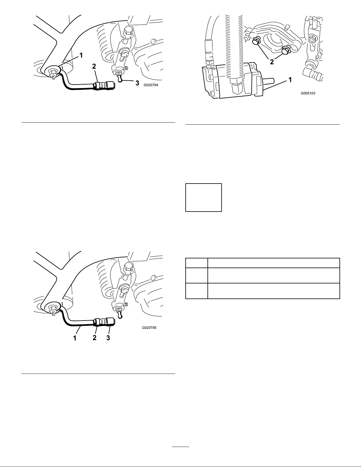
AdjustingtheTransmission forNeutral
Ifthemachinecreepswhenthetractioncontrolpedalisin
theneutralposition,theneutralreturnmechanismmustbe
adjusted.
D.Fromeachsideofthebulkhead,tightenthe
locknutsevenly,securingthetractioncabletothe
bulkhead(Figure52)Donottwistthecable.
Note:Ifcabletensionexistswhenthefunctional
controlleverisinneutral,themachinemaycreep
whentheleverismovedtotheMoworTransport
position.
AdjustingtheTransportSpeed
1.Blockupundertheframesothatoneofthefront
wheelsisoffoftheoor.
Note:Ifmachineisequippedwitha3wheeldrivekit,
therearwheelmustberaisedofftheoorandblocked.
2.Starttheengine,movethethrottletoSlow ,andcheck
thefrontwheelthatisoffoftheoor;itmustnotbe
rotating.
3.Ifthewheelisrotating,stoptheengineandproceed
asfollows:
A.Loosenbothjamnutssecuringthetraction
controlcabletothebulkheadonthehydrostat
Figure52).Makesurethejamnutsareloosened
(
equallyandsufcientlytoallowadjustment.
ObtainingMaximumTransportSpeed
Thetractionpedalisadjustedformaximumtransportspeed
atthefactory,butanadjustmentmayberequiredifthepedal
reachesfullstrokebeforeitcontactsthepedalstop,orifa
decreaseintransportspeedisdesired.
Toobtainmaximumtransportspeed,putthefunctional
controlleverinthetransportpositionandpressdownon
thetractionpedal.Ifthepedalcontactsthestop(Figure53)
beforetensionisfeltonthecable,anadjustmentisrequired:
1.Putthefunctionalcontrolleverinthetransport
positionandloosenthelocknutsecuringthepedalstop
totheoorplate(
2.Tightenthepedalstopuntilitdoesnotcontactthe
tractionpedal.
3.Continueapplyingalightloadonthetransportpedal
andadjustthepedalstopsoitcontactsthepedalrod
andtightenthenuts.
Important:Thetensiononthecablemustnotbe
excessiveorcablelifewillbereduced.
Figure53).
Figure52
1.Tractioncable4.Eccentric
2.Bulkhead5.Locknut
3.Jamnuts
Note:Loosenthenutsecuringtheeccentricto
thetopofthehydrostat(
B.MovethefunctionalcontrollevertoNeutraland
thethrottletoSlow .Starttheengine.
C.Rotatetheeccentricuntilcreepdoesnotoccurin
eitherdirection.Whenthewheelstopsrotating,
tightenthenutlockingtheeccentricandthe
adjustment(
withthethrottleintheSlowandFastposition.
Figure52).Verifytheadjustment
Figure52).
Figure53
1.Pedalstop
ReducingTransportSpeed
1.Pressdownonthetractionpedalandloosenthe
locknutsecuringthepedalstoptotheoorplate.
2.Loosenthepedalstopuntilthedesiredtransportspeed
isobtained.
37
Page 38

3.Tightenthelocknutsecuringthepedalstop.
BrakeMaintenance
AdjustingtheMowingSpeed
Themachineisadjustedatthefactoryto6.1km/h(3.8mph),
butthespeedmaybevariedifdesired.
1.Loosenthejamnutonthepedallockbolt(
Figure54
1.Pedallockcapscrew
Figure54).
AdjustingtheBrakes
Abrakeadjustmentrodislocatedoneachsideofthemachine
sothatthebrakescanbeequallyadjusted.Adjustthebrakes
asfollows:
1.Whilemovingforwardintransportspeed,pressthe
brakepedal;bothwheelsshouldlockequally.
CAUTION
Testingthebrakesinaconnedareawhere
othersarepresentcouldcauseinjury.
Alwayscheckthebrakesinawide,
open-spaced,atareawhichisfreeofother
personsandobstructionsbeforeandafter
adjustment.
2.Ifthebrakesdonotlockequally,disconnectthe
brakerodsbyremovingthecotterpinandclevispin
(Figure55).
2.Rotatetheboltclockwisetoincreasethemowingspeed
andcounterclockwisetodecreaseit.
3.Tightenthejamnutandcheckthegroundspeed.
Repeatthisprocedure,ifrequired.
Figure55
1.Clevispinandcotterpin3.Clevis
2.Jamnut
3.Loosenthejamnutandadjusttheclevisaccordingly
(Figure55).
4.Assembletheclevistothebrakeshaft(Figure55).
5.Checktheamountoffreetravelofthebrakepedal
whentheadjustmentiscompleted.Thereshouldbe
13to26mm(1/2to1inch)travelbeforethebrake
shoesmakecontactwiththebrakedrums.Adjust,if
necessary,toachievethissetting.
4.Brakeshaft
6.Whilemovingforwardintransportspeed,pressthe
brakepedal;bothbrakesshouldlockequally .Adjust,
ifnecessary.
7.Itisrecommendedthatthebrakesbeburnished
annually;refertothe
38
Break-inPeriod(page22)section.
Page 39

ControlsSystem
AdjustingtheLiftCylinders
Maintenance
AdjustingtheCuttingUnit Lift/Drop
Thecuttingunitlift/dropcircuitisequippedwithaow
controlvalve(Figure56).Thisvalveispresetatthefactory
atapproximately3turnsopen,butanadjustmentmaybe
requiredtocompensatefordifferencesinhydraulicoil
temperatures,mowingspeeds,etc.Ifanadjustmentis
required,proceedasfollows:
Toregulatetheheightofthefrontcuttingunitswhenin
theraised(transport)position,youcanadjustthefrontlift
cylinders.
1.Lowerthecuttingunitstotheground.
2.Loosenthejamnutontheclevisofthecuttingunitlift
cylinderthatneedstobeadjusted.
3.Disconnectthecylinderclevisfromtheliftarm.
4.Rotatetheclevisuntilyouattainthedesiredheight.
5.Connectthecylinderclevistotheliftarmandtighten
thejamnut.
Figure56
1.Flowcontrolvalve
Note:Allowthehydraulicoiltoreachfulloperating
temperaturebeforeadjustingtheowcontrolvalve.
1.Raisetheseatandlocatetheowcontrolvalveforthe
centerpullframe(
sideofthehydraulicmanifold.
2.Loosenthejamnutontheadjustingknobontheow
control.
3.Rotatetheknob1/4turncounterclockwiseifthecenter
cuttingunitisdroppingtoolateor1/4turnclockwise
ifthecentercuttingunitisdroppingtooearly.
4.Afterthedesiredsettinghasbeenachieved,tightenthe
setscrew.
Figure56)whichislocatedonthe
39
Page 40

HydraulicSystem
Maintenance
ChangingtheHydraulicOil andFilter
CheckingtheHydraulicLines andHoses
WARNING
Hydraulicuidescapingunderpressurecan
penetrateskinandcauseinjury.
Changethehydraulicoilafterevery800operatinghours.
Iftheoilbecomescontaminated,contactyourlocalT oro
distributorbecausethesystemmustbeushed.Contaminated
oillooksmilkyorblackwhencomparedtocleanoil.
Changethelter:
•Aftertherst50operatinghours
•Afterevery800operatinghours
1.Cleantheareaaroundtheltermountingarea
(Figure57).Placeadrainpanunderthelterand
removethelter.
•Makesureallhydraulicuidhosesandlinesare
ingoodconditionandallhydraulicconnections
andttingsaretightbeforeapplyingpressureto
thehydraulicsystem.
•Keepyourbodyandhandsawayfrompin
holeleaksornozzlesthatejecthighpressure
hydraulicuid.
•Usecardboardorpapertondhydraulicleaks.
•Safelyrelieveallpressureinthehydraulicsystem
beforeperforminganyworkonthehydraulic
system.
•Getimmediatemedicalhelpifuidisinjected
intoskin.
Checkthehydrauliclinesandhosesdailyforleaks,kinked
lines,loosemountingsupports,wear,loosettings,weather
deterioration,andchemicaldeterioration.Makeallnecessary
repairsbeforeoperating.
Figure57
1.Hydrauliclter
Note:Iftheoilisnotgoingtobedrained,disconnect
andplugthehydrauliclinegoingtothelter.
2.Fillthereplacementlterwiththeappropriatehydraulic
uid,lubricatethesealinggasket,andhandturnituntil
thegasketcontactsthelterhead.Thentighten3/4
turnfurther.
3.Fillthehydraulicreservoirandsmallauxiliarytankwith
approximately32l(8-1/2gallons)ofhydraulicoil;refer
CheckingtheHydraulicFluidLevel(page20).
to
4.Startthemachineandrunitatidlefor3to5minutes
tocirculatetheuidandremoveanyairtrappedinthe
system.Stopthemachineandrechecktheuidlevel.
5.Disposeoftheoilandlterproperly .
Note:Iftheleakdetectoralarmsounds,turnthekey
offandwaitafewminutesfortheoilleveltoequalize
inthetanks.Rechecktheuidlevelandaddoil,if
required.
40
Page 41

CuttingUnitMaintenance
Backlapping
WARNING
Contactwiththereelsorothermovingpartscan
resultinpersonalinjury.
•Keepngers,hands,andclothingawayfromthe
reelsorothermovingparts.
•Neverattempttoturnthereelsbyhandorfoot
whiletheengineisrunning.
1.Positionthemachineonalevelsurface,lowerthe
cuttingunits,stoptheengineandengagetheparking
brake.
2.Unlockandraisetheseattoexposethecontrols.
3.Makeinitialreeltobedknifeadjustmentsappropriate
forbacklappingonallcuttingunitswhicharetobe
backlapped;refertotheCuttingUnitOperator'sManual.
9.Ifthereelsstallorbecomeerraticwhilebacklapping,
selectahigherreelspeedsettinguntilthespeed
stabilizes,thenreturnthereelspeedtosetting1orto
yourdesiredspeed.
10.Tomakeanadjustmenttothecuttingunitswhile
backlapping,turnthereelsoffbymovingtheLower
Mow/Raiseleverrearwardandstoptheengine.After
completingadjustments,repeatsteps4through8.
11.Repeattheprocedureforallcuttingunitsyouwantto
backlap.
12.Whennished,returnthebacklapleverstothe
"F"position,lowertheseat,andwashalllapping
compoundoffofthecuttingunits.Adjustcuttingunit
reeltobedknifeasneeded.Movethecuttingunitreel
speedcontroltothedesiredmowingposition.
Important:Ifthebacklapleverisnotreturned
tothe“F”positionafterbacklapping,thecutting
unitswillnotraiseorfunctionproperly.
DANGER
Changingtheenginespeedwhilebacklapping
maycausethereelstostall.
•Neverchangetheenginespeedwhile
backlapping.
•Onlybacklapatidleenginespeed.
4.Starttheengineandrunatlowidlespeed.
5.RotatetheBacklapLevertothe“R”position
(Figure58).
6.RotatetheReelSpeedControltosetting1(
Figure58).
Figure58
1.Backlaplever2.Reelspeedcontrol
7.WiththeMow/Transportleverintheneutralposition,
movetheLowerMow/Liftcontrolforwardtostartthe
backlappingoperationonthedesignatedreels.
8.Applylappingcompoundwithalonghandlebrush.
Neveruseashorthandledbrush.
41
Page 42

Storage
Ifyouwishtostorethemachineforalongperiodoftime,the
followingstepsshouldbeperformedpriortostorage:
1.Removeaccumulationsofdirtandoldgrassclippings.
Sharpenthereelsandbedknives,ifnecessary;
refertotheCuttingUnitOperator'sManual.Use
arustpreventiveonbedknivesandreelblades.
Greaseandoilalllubricationpoints;referto
GreasingtheMachine(page31).
2.Blockupthewheelstoremoveanyweightonthetires.
3.Drainandreplacethehydraulicuid
andlterandinspectthehydrauliclines
andttings.Replace,ifnecessary;refer
toChangingtheHydraulicOilandFilter(page40)and
CheckingtheHydraulicLinesandHoses(page40).
4.Allfuelshouldberemovedfromthefueltank.Runthe
engineuntilitstopsfromlackoffuel.Replacethefuel
lter;refertoReplacingtheFuelFilter(page35).
5.Whiletheengineisstillwarm,draintheoilfrom
thecrankcase.Rellitwithfreshoil;referto
ChangingtheEngineOilandFilter(page33).
6.Removethesparkplugs,pouroneounceofSAE
30oilintothecylinders,andcrankslowlyto
distributetheoil.Replacethesparkplugs;referto
ReplacingtheSparkPlugs(page35).
7.Cleandirtandchafffromthecylinder,cylinderhead
ns,andblowerhousing.
8.Removethebatteryandchargeitfully.Eitherstore
itontheshelforonthemachine.Leavethecables
disconnectedifitisstoredonthemachine.Store
thebatteryinacoolatmospheretoavoidquick
deteriorationofthechargeinthebattery.
9.Ifpossible,storethemachineinawarm,drylocation.
42
Page 43

Schematics
G017140
ElectricalSchematic,Part1(Rev.A)
43
Page 44

G017141
ElectricalSchematic,Part2(Rev.A)
44
Page 45

G017142
HydraulicSchematic,Part1(Rev.A)
45
Page 46

G017143
HydraulicSchematic,Part2(Rev.A)
46
Page 47

Notes:
47
Page 48

TheT oroTotalCoverageGuarantee
ALimitedWarranty
ConditionsandProductsCovered
TheToroCompanyanditsafliate,T oroWarrantyCompany ,pursuant
toanagreementbetweenthem,jointlywarrantyourT oroCommercial
product(“Product”)tobefreefromdefectsinmaterialsorworkmanship
fortwoyearsor1500operationalhours*,whicheveroccursrst.This
warrantyisapplicabletoallproductswiththeexceptionofAerators
(refertoseparatewarrantystatementsfortheseproducts).Wherea
warrantableconditionexists,wewillrepairtheProductatnocosttoyou
includingdiagnostics,labor ,parts,andtransportation.Thiswarranty
beginsonthedatetheProductisdeliveredtotheoriginalretailpurchaser.
*Productequippedwithanhourmeter.
InstructionsforObtainingWarrantyService
YouareresponsiblefornotifyingtheCommercialProductsDistributoror
AuthorizedCommercialProductsDealerfromwhomyoupurchasedthe
Productassoonasyoubelieveawarrantableconditionexists.Ifyouneed
helplocatingaCommercialProductsDistributororAuthorizedDealer,or
ifyouhavequestionsregardingyourwarrantyrightsorresponsibilities,
youmaycontactusat:
ToroCommercialProductsServiceDepartment
ToroWarrantyCompany
811 1LyndaleAvenueSouth
Bloomington,MN55420-1 196
952–888–8801or800–952–2740
E-mail:commercial.warranty@toro.com
OwnerResponsibilities
AstheProductowner ,youareresponsibleforrequiredmaintenance
andadjustmentsstatedinyourOperator'sManual.Failuretoperform
requiredmaintenanceandadjustmentscanbegroundsfordisallowinga
warrantyclaim.
ItemsandConditionsNotCovered
Notallproductfailuresormalfunctionsthatoccurduringthewarranty
periodaredefectsinmaterialsorworkmanship.Thiswarrantydoesnot
coverthefollowing:
•Productfailureswhichresultfromtheuseofnon-Tororeplacement
parts,orfrominstallationanduseofadd-on,ormodiednon-T oro
brandedaccessoriesandproducts.Aseparatewarrantymaybe
providedbythemanufactureroftheseitems.
•Productfailureswhichresultfromfailuretoperformrecommended
maintenanceand/oradjustments.Failuretoproperlymaintainyour
ToroproductpertheRecommendedMaintenancelistedinthe
Operator’sManualcanresultinclaimsforwarrantybeingdenied.
•ProductfailureswhichresultfromoperatingtheProductinan
abusive,negligent,orrecklessmanner.
•Partssubjecttoconsumptionthroughuseunlessfoundtobe
defective.Examplesofpartswhichareconsumed,orusedup,
duringnormalProductoperationinclude,butarenotlimitedto,brake
padsandlinings,clutchlinings,blades,reels,rollersandbearings
(sealedorgreasable),bedknives,sparkplugs,castorwheelsand
bearings,tires,lters,belts,andcertainsprayercomponentssuchas
diaphragms,nozzles,andcheckvalves,etc.
•Failurescausedbyoutsideinuence.Conditionsconsideredtobe
outsideinuenceinclude,butarenotlimitedto,weather,storage
practices,contamination,useofunapprovedfuels,coolants,
lubricants,additives,fertilizers,water,orchemicals,etc.
•Failureorperformanceissuesduetotheuseoffuels(e.g.gasoline,
diesel,orbiodiesel)thatdonotconformtotheirrespectiveindustry
standards.
•Normalnoise,vibration,wearandtear,anddeterioration.
•Normal“wearandtear”includes,butisnotlimitedto,damageto
seatsduetowearorabrasion,wornpaintedsurfaces,scratched
decalsorwindows,etc.
Parts
Partsscheduledforreplacementasrequiredmaintenancearewarranted
fortheperiodoftimeuptothescheduledreplacementtimeforthatpart.
Partsreplacedunderthiswarrantyarecoveredforthedurationofthe
originalproductwarrantyandbecomethepropertyofT oro.T orowill
makethenaldecisionwhethertorepairanyexistingpartorassemblyor
replaceit.T oromayuseremanufacturedpartsforwarrantyrepairs.
DeepCycleandLithium-IonBatteryWarranty:
DeepcycleandLithium-Ionbatterieshaveaspeciedtotalnumberof
kilowatt-hourstheycandeliverduringtheirlifetime.Operating,recharging,
andmaintenancetechniquescanextendorreducetotalbatterylife.Asthe
batteriesinthisproductareconsumed,theamountofusefulworkbetween
chargingintervalswillslowlydecreaseuntilthebatteryiscompletelyworn
out.Replacementofwornoutbatteries,duetonormalconsumption,
istheresponsibilityoftheproductowner.Batteryreplacementmaybe
requiredduringthenormalproductwarrantyperiodatowner’sexpense.
Note:(Lithium-Ionbatteryonly):ALithium-Ionbatteryhasapartonly
proratedwarrantybeginningyear3throughyear5basedonthetime
inserviceandkilowatthoursused.RefertotheOperator'sManualfor
additionalinformation.
MaintenanceisatOwner’sExpense
Enginetune-up,lubrication,cleaningandpolishing,replacementoflters,
coolant,andcompletingrecommendedmaintenancearesomeofthe
normalservicesT oroproductsrequirethatareattheowner’sexpense.
GeneralConditions
RepairbyanAuthorizedT oroDistributororDealerisyoursoleremedy
underthiswarranty .
NeitherTheToroCompanynorToroWarrantyCompanyisliablefor
indirect,incidentalorconsequentialdamagesinconnectionwiththe
useoftheToroProductscoveredbythiswarranty ,includingany
costorexpenseofprovidingsubstituteequipmentorserviceduring
reasonableperiodsofmalfunctionornon-usependingcompletion
ofrepairsunderthiswarranty.ExceptfortheEmissionswarranty
referencedbelow,ifapplicable,thereisnootherexpresswarranty .
Allimpliedwarrantiesofmerchantabilityandtnessforuseare
limitedtothedurationofthisexpresswarranty .
Somestatesdonotallowexclusionsofincidentalorconsequential
damages,orlimitationsonhowlonganimpliedwarrantylasts,sothe
aboveexclusionsandlimitationsmaynotapplytoyou.Thiswarranty
givesyouspeciclegalrights,andyoumayalsohaveotherrightswhich
varyfromstatetostate.
Noteregardingenginewarranty:
TheEmissionsControlSystemonyourProductmaybecoveredby
aseparatewarrantymeetingrequirementsestablishedbytheU.S.
EnvironmentalProtectionAgency(EPA)and/ortheCaliforniaAir
ResourcesBoard(CARB).Thehourlimitationssetforthabovedonot
applytotheEmissionsControlSystemWarranty.RefertotheEngine
EmissionControlWarrantyStatementsuppliedwithyourproductor
containedintheenginemanufacturer’sdocumentationfordetails
CountriesOtherthantheUnitedStatesorCanada
CustomerswhohavepurchasedT oroproductsexportedfromtheUnitedStatesorCanadashouldcontacttheirT oroDistributor(Dealer)toobtain
guaranteepoliciesforyourcountry ,province,orstate.IfforanyreasonyouaredissatisedwithyourDistributor'sserviceorhavedifcultyobtaining
guaranteeinformation,contacttheT oroimporter .
374-0253RevB
 Loading...