

Page 1

Form No. 3327-360
Greensmaster 3100 Two-Wheel Drive
Greensmaster Traction Unit
Model No. 04356—Serial No. 210000001 and Up
Operator ’s Manual
Domestic English (EN)
Page 2

Warning
The engine exhaust from this product contains
chemicals known to the State of California to cause
cancer, birth defects, or other reproductive harm.
Important The engine in this product is not equipped
with a spark arrester muffler. It is a violation of California
Public Resource Code Section 4442 to use or operate this
engine on any forest-covered, brush-covered, or
grass-covered land as defined in CPRC 4126. Other states
or federal areas may have similar laws.
This spark ignition system complies with Canadian
ICES-002.
Ce système d’allumage par étincelle de véhicule est
conforme à la norme NMB-002 du Canada.
Contents
Page
Introduction 2. . . . . . . . . . . . . . . . . . . . . . . . . . . . . . . . .
Safety 3. . . . . . . . . . . . . . . . . . . . . . . . . . . . . . . . . . . . . .
Safe Operating Practices 3. . . . . . . . . . . . . . . . . . . .
Toro Mower Safety 4. . . . . . . . . . . . . . . . . . . . . . . .
Sound Pressure 6. . . . . . . . . . . . . . . . . . . . . . . . . . . .
Sound Power 6. . . . . . . . . . . . . . . . . . . . . . . . . . . . .
Vibration 6. . . . . . . . . . . . . . . . . . . . . . . . . . . . . . . . .
Safety and Instruction Decals 6. . . . . . . . . . . . . . . . .
Specifications 9. . . . . . . . . . . . . . . . . . . . . . . . . . . . . . . .
General Specifications 9. . . . . . . . . . . . . . . . . . . . . .
Accessories 9. . . . . . . . . . . . . . . . . . . . . . . . . . . . . . .
Assembly 9. . . . . . . . . . . . . . . . . . . . . . . . . . . . . . . . . . .
Activating and Charging the Battery 10. . . . . . . . . . .
Mounting the Seat 11. . . . . . . . . . . . . . . . . . . . . . . . .
Installing the Battery 11. . . . . . . . . . . . . . . . . . . . . . .
Installing the Steering Wheel 12. . . . . . . . . . . . . . . . .
Installing the Cutting Units 12. . . . . . . . . . . . . . . . . .
Rear Ballast 14. . . . . . . . . . . . . . . . . . . . . . . . . . . . . .
Before Operating 14. . . . . . . . . . . . . . . . . . . . . . . . . . . . .
Checking the Engine Oil 14. . . . . . . . . . . . . . . . . . . .
Filling the Gas Tank 15. . . . . . . . . . . . . . . . . . . . . . . .
Servicing the Hydraulic System 15. . . . . . . . . . . . . . .
Tire Pressure 17. . . . . . . . . . . . . . . . . . . . . . . . . . . . . .
Checking the Torque of the Wheel Nuts 17. . . . . . . .
Operation 17. . . . . . . . . . . . . . . . . . . . . . . . . . . . . . . . . . .
Think Safety First 17. . . . . . . . . . . . . . . . . . . . . . . . . .
Controls 18. . . . . . . . . . . . . . . . . . . . . . . . . . . . . . . . .
Break-in Period 20. . . . . . . . . . . . . . . . . . . . . . . . . . .
Starting the Engine 20. . . . . . . . . . . . . . . . . . . . . . . . .
Page
Checking the Interlock System 21. . . . . . . . . . . . . . .
Checking the Leak Detector (Fig. 22–25) 22. . . . . . .
Preparing the Machine for Mowing 23. . . . . . . . . . . .
Training Period 23. . . . . . . . . . . . . . . . . . . . . . . . . . . .
Before Mowing 23. . . . . . . . . . . . . . . . . . . . . . . . . . .
Mowing Procedures 23. . . . . . . . . . . . . . . . . . . . . . . .
Leak Detector Operation 24. . . . . . . . . . . . . . . . . . . .
Transport Operation 24. . . . . . . . . . . . . . . . . . . . . . . .
Inspection and Cleanup After Mowing 25. . . . . . . . .
Maintenance 25. . . . . . . . . . . . . . . . . . . . . . . . . . . . . . . . .
Recommended Maintenance Schedule 25. . . . . . . . .
Daily Maintenance Checklist 26. . . . . . . . . . . . . . . . .
Lubrication 27. . . . . . . . . . . . . . . . . . . . . . . . . . . . . . .
Changing the Engine Oil and Filter 29. . . . . . . . . . . .
Servicing the Air Cleaner 29. . . . . . . . . . . . . . . . . . . .
Adjusting the Throttle Control 30. . . . . . . . . . . . . . . .
Adjusting the Choke Control 30. . . . . . . . . . . . . . . . .
Adjusting the Carburetor and Speed Control 30. . . . .
Replacing the Spark Plugs 31. . . . . . . . . . . . . . . . . . .
Replacing the Fuel Filter 31. . . . . . . . . . . . . . . . . . . .
Changing the Hydraulic Oil and Filter 32. . . . . . . . . .
Checking the Hydraulic Lines and Hoses 32. . . . . . .
Adjusting the Brakes 32. . . . . . . . . . . . . . . . . . . . . . .
Adjusting the Rear Camshaft 33. . . . . . . . . . . . . . . . .
Adjusting the Lift and Mow Pedal Height 34. . . . . . .
Leveling the Lift and Mow Pedals 34. . . . . . . . . . . . .
Adjusting the Traction Pedal 35. . . . . . . . . . . . . . . . .
Adjusting Cutting Unit Lift and Drop 35. . . . . . . . . .
Adjusting the Lift Cylinders 35. . . . . . . . . . . . . . . . .
Replacing the Seat Switch 36. . . . . . . . . . . . . . . . . . .
Replacing the Traction Switch 36. . . . . . . . . . . . . . . .
Replacing the Mow/Lift Switch 36. . . . . . . . . . . . . . .
Adjusting the Traction Return Linkage 37. . . . . . . . .
Battery Care 37. . . . . . . . . . . . . . . . . . . . . . . . . . . . . .
Storage 38. . . . . . . . . . . . . . . . . . . . . . . . . . . . . . . . . .
Electrical Schematic 39. . . . . . . . . . . . . . . . . . . . . . . .
Hydraulic Schematic 40. . . . . . . . . . . . . . . . . . . . . . .
Troubleshooting 41. . . . . . . . . . . . . . . . . . . . . . . . . . . . . .
The Toro General Commercial Products Warranty 48. . .
Introduction
Read this manual carefully to learn how to operate and
maintain your product properly. The information in this
manual can help you and others avoid injury and product
damage. Although Toro designs and produces safe
products, you are responsible for operating the product
properly and safely.
2002 by The Toro Company
8111 Lyndale Avenue South
Bloomington, MN 55420-1196
All Rights Reserved
2
Printed in the USA
Page 3

Whenever you need service, genuine Toro parts, or
additional information, contact an Authorized Toro
Distributor or Toro Customer Service and have the model
and serial numbers of your product ready. Figure 1
illustrates the location of the model and serial numbers on
the product.
1
Safety
This machine meets or exceeds the B71.4 1999
specifications of the American National Standards
Institute, in effect at time of production, when 40 lb. of
ballast is added to the rear wheel.
Note: The addition of attachments made by other
manufacturers that do not meet American National
Standards Institute certification will cause noncompliance
of this machine.
Improper use or maintenance by the operator or owner
can result in injury. To reduce the potential for injury,
comply with these safety instructions and always pay
attention to the safety alert
CAUTION, WARNING, or DANGER—“personal
safety instruction.” Failure to comply with the
instruction may result in personal injury or death.
Safe Operating Practices
symbol, which means
Figure 1
1. Location of the model and serial numbers
Write the product model and serial numbers in the space
below:
Model No:
Serial No.
This manual identifies potential hazards and has special
safety messages that help you and others avoid personal
injury and even death. Danger, Warning, and Caution are
signal words used to identify the level of hazard. However,
regardless of the hazard, be extremely careful.
Danger signals an extreme hazard that will cause serious
injury or death if you do not follow the recommended
precautions.
Warning signals a hazard that may cause serious injury or
death if you do not follow the recommended precautions.
Caution signals a hazard that may cause minor or moderate
injury if you do not follow the recommended precautions.
This manual uses two other words to highlight information.
Important calls attention to special mechanical
information and Note: emphasizes general information
worthy of special attention.
The following instructions are from ANSI standard
B71.4—1999.
Training
• Read the Operator’s Manual and other training material.
If the operator(s) or mechanic(s) can not read English it
is the owner’s responsibility to explain this material to
them.
• Become familiar with the safe operation of the
equipment, operator controls, and safety signs.
• All operators and mechanics should be trained. The
owner is responsible for training the users.
• Never let children or untrained people operate or
service the equipment. Local regulations may restrict
the age of the operator.
• The owner/user can prevent and is responsible for
accidents or injuries occurring to himself or herself,
other people or property.
Preparation
• Evaluate the terrain to determine what accessories and
attachments are needed to properly and safely perform
the job. Only use accessories and attachments approved
by the manufacturer.
• Wear appropriate clothing including hard hat, safety
glasses and ear protection. Long hair, loose clothing or
jewelry may get tangled in moving parts.
• Inspect the area where the equipment is to be used and
remove all objects such as rocks, toys and wire which
can be thrown by the machine.
3
Page 4

• Use extra care when handling gasoline and other fuels.
They are flammable and vapors are explosive.
– Use only an approved container.
– Never remove gas cap or add fuel with engine
running. Allow engine to cool before refueling. Do
not smoke.
– Never refuel or drain the machine indoors.
• Check that operator’s presence controls, safety switches
and shields are attached and functioning properly. Do
not operate unless they are functioning properly.
• Use care when approaching blind corners, shrubs, trees,
or other objects that may obscure vision.
Maintenance and Storage
• Disengage drives, raise the cutting units, set parking
brake, stop engine and remove key and disconnect spark
plug wire. Wait for all movement to stop before
adjusting, cleaning or repairing.
• Clean grass and debris from cutting units, drives,
mufflers, and engine to help prevent fires. Clean up oil
or fuel spillage.
Operation
• Never run an engine in an enclosed area.
• Only operate in good light, keeping away from holes
and hidden hazards.
• Be sure all drives are in neutral and parking brake is
engaged before starting engine. Only start engine from
the operator’s position. Use seat belts if provided.
• Slow down and use extra care on hillsides. Be sure to
travel in the recommended direction on hillsides. Turf
conditions can affect the machine’s stability. Use
caution while operating near drop-offs.
• Slow down and use caution when making turns and
when changing directions on slopes.
• Never operate with guards not securely in place. Be
sure all interlocks are attached, adjusted properly, and
functioning property.
• Do not change the engine governor setting or overspeed
the engine.
• Stop on level ground, raise the cutting units, disengage
drives, engage parking brake (if provided), shut off
engine before leaving the operator’s position for any
reason including emptying the grass baskets.
• Stop equipment and inspect the machine after striking
objects or if an abnormal vibration occurs. Make
necessary repairs before resuming operations.
• Let engine cool before storing and do not store near
flame.
• Shut off fuel while storing or transporting. Do not store
fuel near flames or drain indoors.
• Park machine on level ground. Never allow untrained
personnel to service machine.
• Use jack stands to support components when required.
• Carefully release pressure from components with stored
energy.
• Disconnect battery and remove spark plug wire before
making any repairs. Disconnect the negative terminal
first and the positive last. Reconnect positive first and
negative last.
• Use care when checking the reels. Wear gloves and use
caution when servicing them.
• Keep hands and feet away from moving parts. If
possible, do not make adjustments with the engine
running.
• Charge batteries in an open well ventilated area, away
from spark and flames. Unplug charger before
connecting or disconnecting from battery. Wear
protective clothing and use insulated tools.
• Keep all parts in good working condition and all
hardware and hydraulic fittings tightened. Replace all
worn or damaged decals.
• Keep hands and feet away from the cutting units.
• Look behind and down before backing up to be sure of
a clear path.
• Never carry passengers and keep pets and bystanders
away.
• Slow down and use caution when making turns and
crossing roads and sidewalks. Stop reels if not mowing.
• Do not operate the mower under the influence of
alcohol or drugs
• Use care when loading or unloading the machine into a
trailer or truck
Toro Mower Safety
The following list contains safety information specific to
Toro products or other safety information that you must
know that is not included in the ANSI standards.
This product is capable of amputating hands and feet and
throwing objects. Always follow all safety instructions to
avoid serious injury or death.
Use of this product for purposes other than its intended use
could prove dangerous to user and bystanders.
4
Page 5

Operation
• Know how to stop the engine quickly.
• Always wear substantial shoes. Do not operate the
machine while wearing sandals, tennis shoes, or
sneakers.
• Wearing safety shoes and long pants is advisable and
required by some local ordinances and insurance
regulations.
• Handle gasoline carefully. Wipe up any spills.
• Check the safety interlock switches daily for proper
operation. If a switch should fail, replace the switch
before operating the machine. After every two years,
replace all four interlock switches in the safety system,
regardless if they are working properly or not.
• Before starting the engine, sit on the seat, depress the
lift pedal, and release it to ensure the cutting units are
disengaged. Verify that the traction system is in neutral
and the parking brake is set.
• Using the machine demands attention. To prevent loss
of control:
– Do not drive close to sand traps, ditches, creeks, or
other hazards.
– Reduce speed when making sharp turns. Avoid
sudden stops and starts.
– Watch out for traffic when near or crossing roads.
Always yield the right-of-way.
– Apply the service brakes when going downhill to
keep forward speed slow and to maintain control of
the machine.
• The grass baskets must be in place during operation of
the reels or thatchers for maximum safety. Shut the
engine off before emptying the baskets.
• Raise the cutting units when driving from one work
area to another.
• Do not touch the engine, muffler, or exhaust pipe while
the engine is running or soon after it has stopped
because these areas could be hot enough to cause burns.
• Stay clear of the rotating screen at the side of the engine
to prevent direct contact with your body or clothing.
• If a cutting unit strikes a solid object or vibrates
abnormally, stop immediately, turn the engine off, wait
for all motion to stop, and inspect the machine for
damage. A damaged reel or bedknife must be repaired
or replaced before operation is continued.
• Before getting off of the seat, move the shift selector to
N neutral, depress the lift pedal to raise the cutting
units, wait for the reels to stop spinning, and release lift
pedal. Set the parking brake. Stop the engine and
remove the key from the ignition switch.
• Traverse slopes carefully. Do not start or stop suddenly
when traveling uphill or downhill.
• The operator must be skilled and trained in how to drive
on hillsides. Failure to use caution on slopes or hills
may cause loss of control and cause the vehicle to tip or
roll, possibly resulting in personal injury or death.
• If the engine stalls or loses headway and cannot make it
to the top of a slope, do not turn the machine around.
Always back slowly, straight down the slope.
• When a person or pet appears unexpectedly in or near
the mowing area, stop mowing. Careless operation,
combined with terrain angles, ricochets, or improperly
positioned guards can lead to thrown object injuries. Do
not resume mowing until the area is cleared.
• Whenever the machine is left unattended, make sure the
cutting units are fully raised and the reels are not
spinning, the key is removed from the ignition switch,
and the parking brake is set.
Maintenance and Storage
• Make sure all hydraulic line connectors are tight and all
hydraulic hoses and lines are in good condition before
applying pressure to the system.
• Keep your body and hands away from pin hole leaks or
nozzles that eject hydraulic fluid under high pressure.
Use paper or cardboard, not your hands, to search for
leaks. Hydraulic fluid escaping under pressure can have
sufficient force to penetrate the skin and cause serious
injury.
• Before disconnecting or performing any work on the
hydraulic system, all pressure in the system must be
relieved by stopping the engine and lowering the cutting
units and attachments to the ground.
• Check all fuel lines for tightness and wear on a regular
basis. Tighten or repair them as needed.
• If the engine must be running to perform a maintenance
adjustment, keep hands, feet, clothing, and any parts of
the body away from the cutting units, attachments, and
any moving parts, especially the screen at the side of the
engine. Keep everyone away.
• Do not overspeed the engine by changing governor
settings. To ensure safety and accuracy, have an
Authorized Toro Distributor check the maximum engine
speed with a tachometer. Maximum governed engine
speed should be 2900 RPM.
• The engine must be shut off before checking the oil or
adding oil to the crankcase.
• If major repairs are ever needed or if assistance is
desired, contact an Authorized Toro Distributor.
5
Page 6
• To make sure of optimum performance and continued
safety certification of the machine, use only genuine
Toro replacement parts and accessories. Replacement
parts and accessories made by other manufacturers
could be dangerous, and such use could void the
product warranty.
Sound Power
This unit has a guaranteed sound power level of 105 dBA,
based on measurements of identical machines per Directive
2000/14/EC.
Sound Pressure
This unit has a maximum sound pressure level at the
operator’s ear of 86 dBA, based on measurements of
identical machines per Directive 98/37/EC.
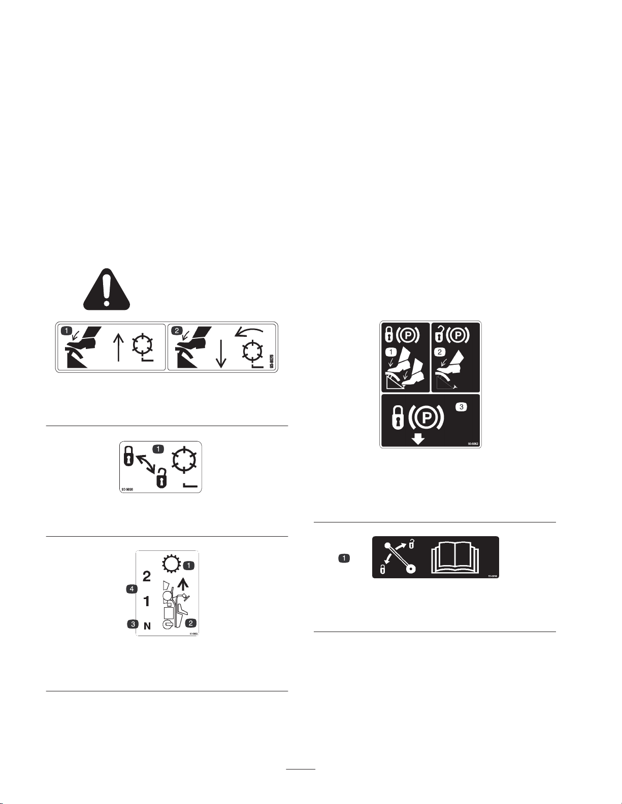
Safety and Instruction Decals
Safety decals and instructions are easily visible to the operator and are located near any area
of potential danger. Replace any decal that is damaged or lost.
93-8075
1. Press the lift pedal to
raise and stop the reels.
2. Press the mow pedal to
lower and start the reels.
Vibration
This unit does not exceed a hand/arm vibration level of
2
2.5 m/s
Directive 98/37/EC.
This unit does not exceed a whole body vibration level of
0.5 m/s2, based on measurements of identical machines per
Directive 98/37/EC.
, based on measurements of identical machines per
1. Lock and unlock the reels
1. Transmission
2. Forward motion
93-9898
93-8065
3. Neutral
4. Forward speeds
1. To lock the parking brake,
press the brake pedal and
the parking brake lock.
1. Read the
unlocking the steering arm.
Operator’s Manual
93-8062
2. To unlock the parking
brake, press the brake
pedal.
3. Parking brake lock
93-8068
for instructions on locking and
6
Page 7
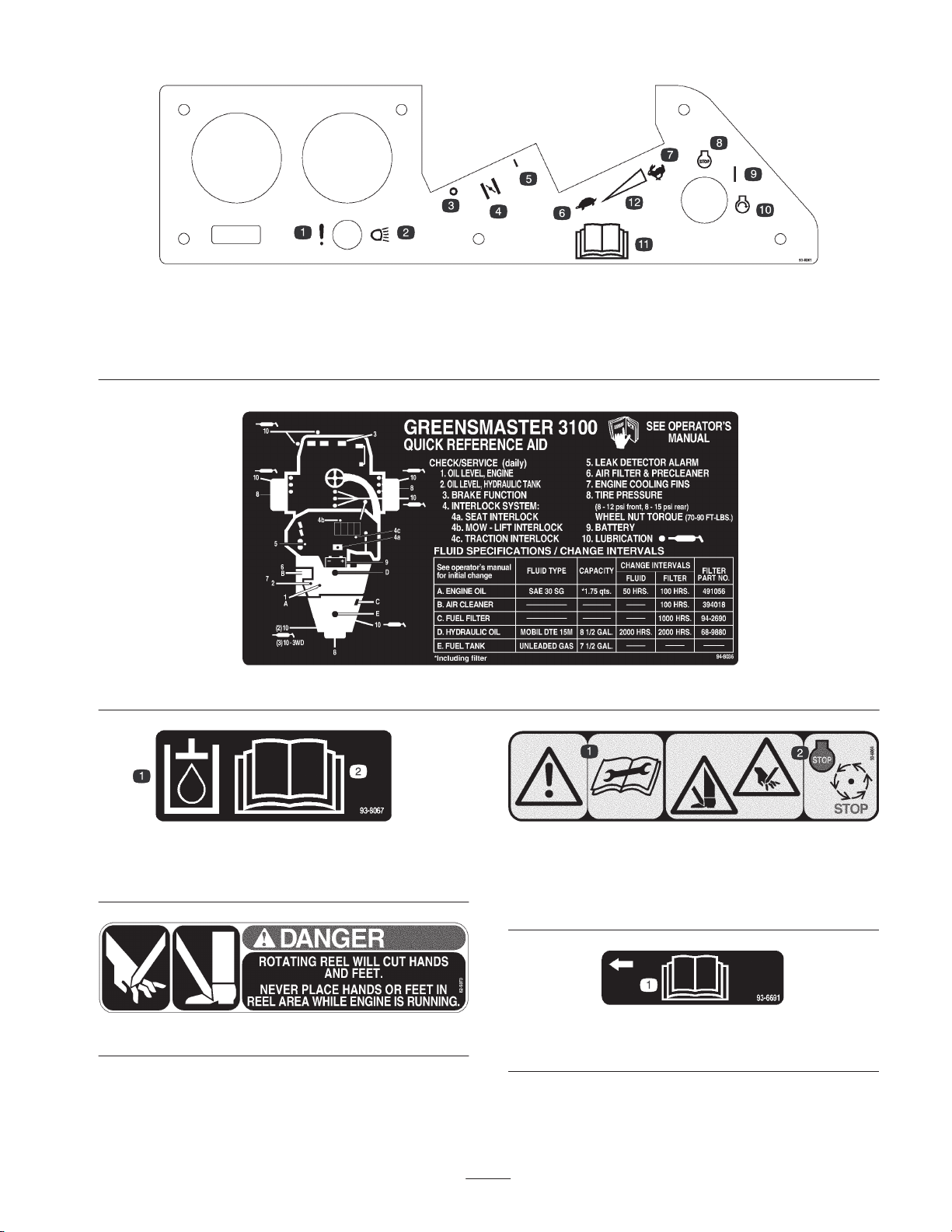
1. Failure/malfunction (Leak
detector alarm test)
2. Headlights
3. Off
4. Choke
5. On
6. Slow
93-8061 (Replace control panel)
7. Fast
8. Engine—stop
9. On
94-8036
10. Engine—start
11. Read the
12. Continuous variable setting
Operator’s Manual.
93-8067
1. Hydraulic oil 2. Read the
Manual.
62–5070
Operator’s
1. Warning—read the
instructions before
servicing or performing
maintenance.
1. Read the
7
93-8064 (for CE)
2. Cutting hazard of foot or
hand—stop the engine
and wait for moving parts
to stop.
93-6691
Operator’s Manual.
Page 8
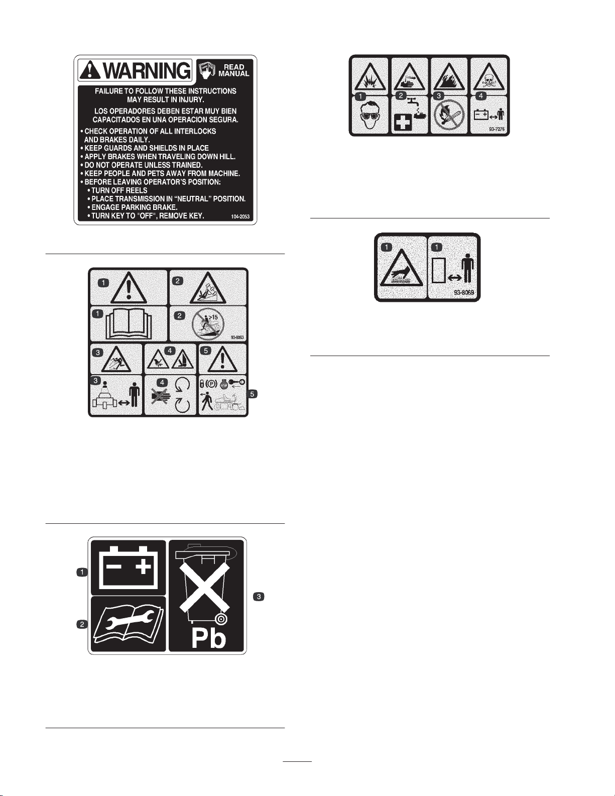
104-2053
93-8063 (for CE)
1. Warning—read the
2. Tipping hazard—do not use the machine on a slope greater
than 15 degrees.
3. Thrown object hazard—stay a safe distance from the machine.
4. Cutting hazard of hand or foot—stay away from moving parts.
5. Warning—lock the parking brake, stop the engine, and remove
the ignition key before leaving the machine.
Operator’s Manual.
93-7276
1. Explosion hazard—wear
eye protection.
2. Caustic liquid/chemical
burn hazard—to perform
first aid, flush with water.
3. Fire hazard—no fire, open
flames, or smoking.
4. Poison hazard—keep
children a safe distance
from the battery.
93-8069
1. Hot surface/burn hazard—stay a safe distance from the hot
surface.
1. Battery
2. Read the instructions
before servicing or
performing maintenance.
93-6668
3. Contains lead; do not
discard.
8
Page 9

Specifications
Accessories
Note: Specifications and design subject to change without
notice.
General Specifications
Width of Cut 59 in. (149.9 cm)
Wheel Tread 49-1/2 in.
(125.7 cm)
Wheel Base 46-7/8 in.
(119.1 cm)
Overall Length 90 in. (228.6 cm)
Overall Width 69-3/4 in.
(117.2 cm)
Overall Height 48-1/2 in.
(123.2 cm)
Net Weight (wet) 1021 lb. (463 kg)
Weight with Reels 1261 lb. (572 kg)
1st Gear Speed 3.8 MPH approx.
(6.1 km/h)
2nd Gear Speed 8.1 MPH approx.
(13.0 km/h)
Reverse Speed 1.9 MPH approx.
(3.1 km/h)
Reel Speed 1975 RPM approx.
Clip Speed—11 Blade Cutting Unit 0.18 in. approx.
(4.6 mm)
Clip Speed—8 Blade Cutting Unit 0.25 in. approx.
(6.4 mm)
8 Blade, 4 Bolt Cutting Unit
(Heavy Duty)
8 Blade, 4 Bolt Cutting Unit Model No. 04408
11 Blade, 4 Bolt Cutting Unit Model No. 04406
8 Blade, SPA Cutting Unit Model No. 04468
11 Blade, SPA Cutting Unit Model No. 04450
8 Blade, 4 Bolt Cutting Unit Model No. 04470
11 Blade, 4 Bolt Cutting Unit Model No. 04471
8 Blade, SPA Cutting Unit Model No. 04472
11 Blade, SPA Cutting Unit Model No. 04473
Spiker Model No. 04494
Tri-Roller Model No. 04495
Groomer Kit (for use with cutting
unit models 04470, 04471, 04472,
and 04473)
Grooming Reel Kit (for use with
cutting unit models 04404, 04408,
04406, 04468, and 04450)
Thatching Reels Model No. 04493
Variable Traction Speed Kit Model No. 04422
Individual Reel Shut Off Kit Part No. 28-2150
Basket Reinforcement Kit Part No. 26-0900
Backlapping Kit Part No. 92-9656
Spark Arrester Part No. 83-2240
Three-Wheel Drive Kit Part No. 100-6441
Service Manual Part No. 92784SL
High Altitude Jet* Part No. 808413
* Order from your local Briggs & Stratton Dealer
Model No. 04404
Model No. 04456
Model No. 04455
Assembly
Note: Determine the left and right side of the machine from the normal operating position.
Description Qty. Use
Seat
Nut, 5/16
Seat cover
Steering wheel
Nut
Cap
Screw
Bolt, 1/4 x 5/8 in.
Nut, 1/4 in.
1
4
1
1
1
1
1
2
2
9
Mounting the seat slides and seat cover to the
seat base
Mounting the steering wheel
Securing the battery cables to the battery
Page 10

Description UseQty.
Gauge bar
Screw, #10 x 5/8 in.
Jam nut, #10
Grass basket 3 Mounts to the pull frame
Ignition keys 2
Warning decal 1
Danger decal 3
Service decal 11
Operator’s Manual (traction unit)
Engine Operator’s Manual
Operator video 1 Watch before operating the machine.
Parts Catalog
Noise rating certificate
Pre-delivery sheet
Certificate of Compliance
1
1
1
2
1
1
1
1
1
Setting the height-of-cut
Affix over English warning decal (104-2053) for
CE.
Affix over English danger decal (62-5070) for
CE.
Affix appropriate language decal over English
service decal (94-8036) for CE.
Read before operating the machine.
Registration Card (traction unit)
Registration Card (cutting unit)
Note: Mounting fasteners for the Greensmaster 3100 cutting unit are included with the cutting units.
Note: Remove the shipping bracket and nut secured to rear wheel bolt.
Activating and Charging the
1
Fill out and return to Toro.
1
Danger
Battery
Battery electrolyte contains sulfuric acid which is a
Warning
Battery posts, terminals, and related accessories
contain lead and lead compounds, chemicals
known to the State of California to cause cancer
and reproductive harm. Wash hands after
handling.
Voltage: 12 v, 32 amp. hour
deadly poison and causes severe burns.
• Do not drink electrolyte and avoid contact with
skin, eyes or clothing. Wear safety glasses to
shield your eyes and rubber gloves to protect
your hands.
• Fill the battery where clean water is always
available for flushing the skin.
1. Remove the wing nuts, washers, and battery clamp and
lift out the battery.
2. Remove the filler caps from the battery and slowly fill
each cell until the electrolyte is up to the fill line.
3. Replace the filler caps and connect a battery charger to
the battery posts. Charge the battery at a rate of 3 to
4 amperes for 4 to 8 hours.
10
Page 11
Warning
Charging the battery produces gasses that can
explode.
Never smoke near the battery and keep sparks and
flames away from battery.
4. When the battery is charged, disconnect the charger
from the electrical outlet and battery posts, and allow
the battery to sit for 5–10 minutes.
5. Remove the filler caps. Slowly add electrolyte to each
cell until the level is up to the fill line. Install the filler
caps.
Important Do not overfill the battery. Electrolyte will
overflow onto other parts of the machine and sever
corrosion and deterioration will result.
Mounting the Seat
Note: Mount the seat slides in the front set of mounting
holes to gain an additional 3 in. (7.6 cm) in the forward
adjustment, or in the rear mounting holes for an additional
3 in. (7.6 cm) in the rearward adjustment.
1. Support the seat base in the up position with the seat
support rod.
2. Remove the locknuts securing the seat slides to the
plywood shipping base. Discard the locknuts.
3. Secure the seat, seat panel, and seat slides to the seat
support with the locknuts (5/16 in.) (Fig. 2) supplied in
the loose parts. Mount the seat panel on the right side,
positioned as shown in Figure 2.
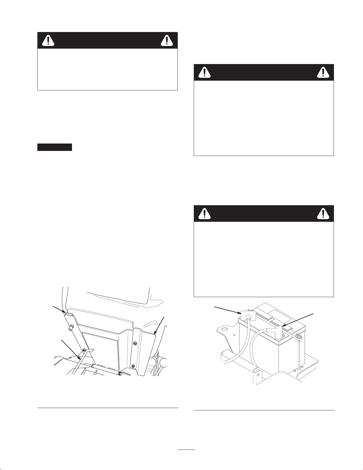
Installing the Battery
1. Mount the battery with the battery terminals toward the
front of the machine.
Warning
Battery terminals or metal tools could short
against metal tractor components causing sparks.
Sparks can cause the battery gasses to explode,
resulting in personal injury.
• When removing or installing the battery, do not
allow the battery terminals to touch any metal
parts of the tractor.
• Do not allow metal tools to short between the
battery terminals and metal parts of the tractor.
2. Connect the positive battery cable (red) from the starter
solenoid to the positive post (+) of the battery (Fig. 3).
Secure it with a wrench and coat the terminal with
petroleum jelly. Make sure the cable will clear the seat,
in the rear-most position, which could cause wear or
damage to the cable.
Warning
Incorrect battery cable routing could damage the
tractor and cables causing sparks. Sparks can
cause the battery gasses to explode, resulting in
personal injury.
• Always disconnect the negative (black) battery
cable before disconnecting the positive (red)
cable.
• Always connect the positive (red) battery cable
before connecting the negative (black) cable.
2
1
1. Seat support rod
2. Seat slide
Figure 2
3. Seat panel
2
3
Figure 3
1. Negative (–) 2. Positive (+)
11
1
Page 12
3. Connect the two black ground cables (one connected to
the engine base, the other to the machine frame) to the
negative (–) post of the battery. Secure it with a wrench
and coat the terminal with petroleum jelly.
4. Install the battery clamp and washers and secure them
with the wing nuts.
2. Slide the cutting units under the pull frames and
position the hoop on the top of cutting units over the lift
arms (Fig. 5).
1
2
5. Place the terminal cover over
post.
the positive (+) battery
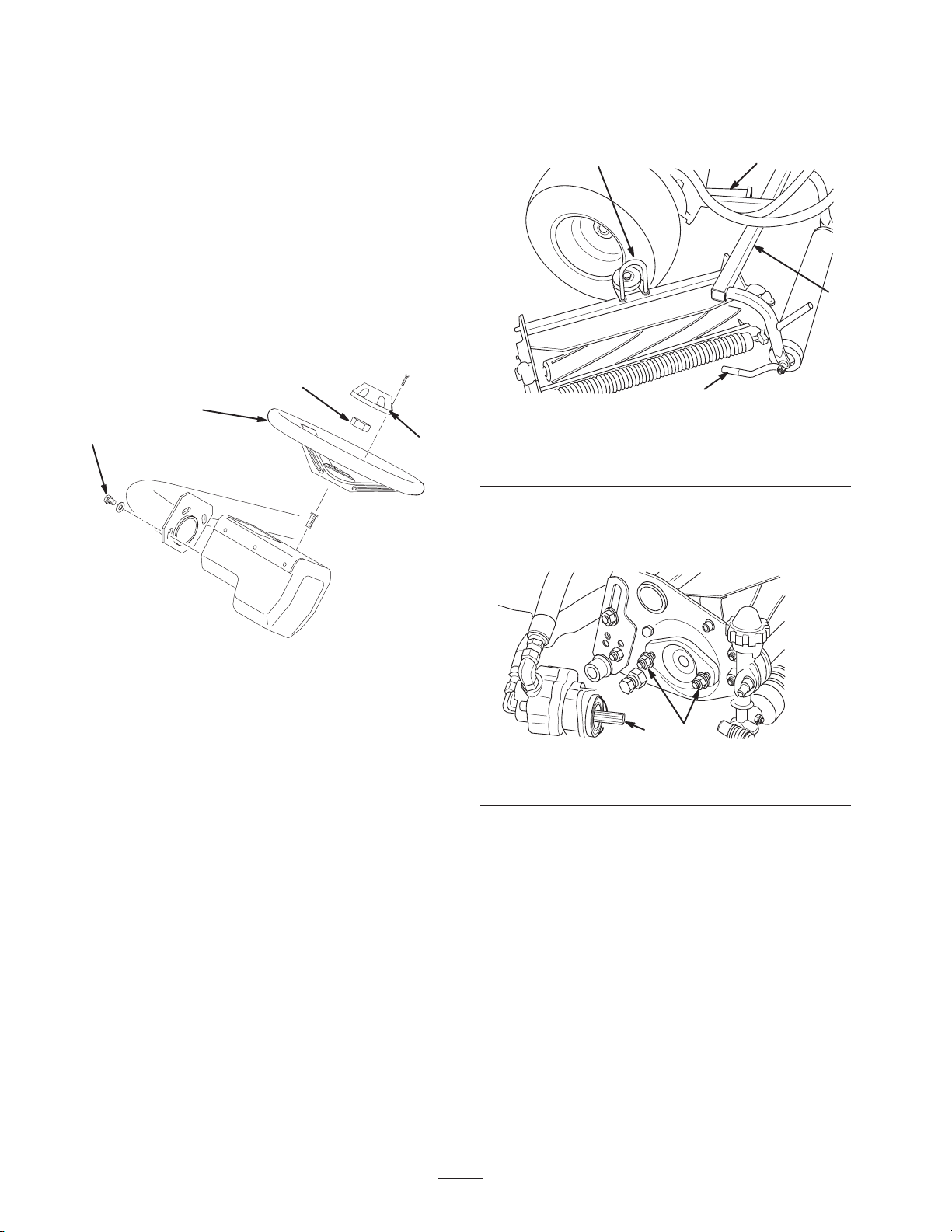
Installing the Steering Wheel
1. Slide the steering wheel onto the steering shaft and
secure it with the jam nut (Fig. 4). Torque it to 35 ft.-lb.
(47 N⋅m).
2
1
4
Figure 4
1. Steering wheel
2. Jam nut
3. Cap
4. Mounting screws
3
4
Figure 5
3
1. Hoop
2. Lift arm
3. Assemble the mount nuts for the reel drive motor to
each cutting unit. Leave approximately 1/2 in. (13 mm)
of threads exposed on each mount stud (Fig. 6).
3. Pull frame
4. Pull arm
2. Install the cap to the steering wheel with the screw
(Fig. 4).
Note: The steering wheel may be adjusted fore and aft for
operator comfort by loosening the three mounting screws,
pivoting the steering wheel to the desired operating
position, and tightening the screws (Fig. 4).
Installing the Cutting Units
For Cutting Unit Models 04404, 04406,
04408, 04450, and 04468
Note: When sharpening, setting the height-of-cut, or
performing other maintenance procedures on the cutting
units, store the cutting unit reel motors in the support tubes
on the front of the frame to prevent damage to the hoses.
1. Remove the cutting units from the cartons. Assemble
and adjust them per the cutting unit Operator’s Manual.
Use the gauge bar from the loose parts kit to adjust the
height of cut.
12
Figure 6
1. Motor mount nuts 2. Coat with grease
4. Remove the protective covers from the cutting units and
the reel drive motor shafts. Coat the spline shaft of the
motor with clean grease and install the motor by
rotating the motor clockwise so the motor flanges clear
the studs. Rotate the motor counterclockwise until the
flanges are encircling the studs and tighten the
mounting nuts (Fig. 6).
Note: Retain the protective covers for the cutting units.
Install them whenever the reel drive motors are
removed to protect the cutting unit bearings from
contamination.
5. Slide the sleeve back on the ball joint and rotate the pull
arm down so the socket fits over the ball stud. Release
the sleeve so it slides over the stud and locks the
assemblies together (Fig. 7).
12
Page 13
For Cutting Unit Models 04470, 04471,
04472, and 04473
Note: When sharpening, setting the height-of-cut or
performing other maintenance procedures on the cutting
units, store the cutting unit reel motors in the support tubes
on the front of the frame to prevent damage to the hoses.
12
Figure 7
1. Slide back to mount 2. Ball stud
6. Mount the baskets on the pull frames, loosen the jam
nuts on the pull arms, and adjust the ball sockets until
there is 1/4 to 1/2 in. (6.4 to 12.7 mm) clearance
between the lip of the basket and the reel blades
(Fig. 8).
Note: This prevents the basket from tipping the cutting
unit forward, causing the hoop to come off of the lift
arm while in the mowing operation.
Note: Be sure the basket lips are equidistant from the
reel blades across each reel. If the basket is too close to
the reel, it is possible for the reel to contact the basket
when the cutting unit is raised off of the ground.
4
1. Remove the cutting units from the cartons. Assemble
and adjust them per the cutting unit Operator’s Manual.
Use the gauge bar from the loose parts kit to adjust the
height of cut.
2. Mount a washer and ball stud to each end of the front
roller on the cutting units (Fig. 9).
3
2
1
4
Figure 9
1. Pull frame
2. Lift roller
3. Lift arm
4. Pull arm
5. Ball stud
5
1 23
Figure 8
1. Jam nut
2. Pull arm
3. Ball joint—adjust for
clearance
4. 1/4–1/2 in. (6.4–12.7 mm)
clearance
7. Align the sockets in the ball joints so the open side of
the socket is centered towards the ball stud. Tighten the
jam nuts to secure the sockets in position (Fig. 8).
3. Slide the cutting unit under the pull frame while
hooking the lift roller onto the lift arm (Fig. 9).
4. Slide the sleeve back on the ball joint and rotate the pull
arm down so the socket fits over the ball stud. Release
the sleeve so it slides over the stud and locks the
assemblies together (Fig. 9).
5. Mount the baskets on the pull frames, loosen the jam
nuts on the pull arms, and adjust the ball sockets until
there is 1/4 to 1/2 in. (6.4 to 12.7 mm) clearance
between the lip of the basket and the reel blades or the
front shield.
Note: This prevents the basket from tipping the cutting
unit forward, causing the lift roller to come off of the
lift arm while in the mowing operation.
Be sure the basket lips are equidistant from the reel
blades all across each reel. If the basket is too close to
the reel, it is possible for the reel to contact the basket
when the cutting unit is raised off of the ground.
13
Page 14
6. Align the sockets in the ball joints so the open side of
the socket is centered towards the ball stud. Tighten the
jam nuts to secure the sockets in position (Fig. 10).
3
1
Rear Ballast
This unit complies with the ANSI B71.4–1999 Standard
when 40 lb. of calcium chloride ballast is added to the rear
wheel.
Important If a puncture occurs in a tire with calcium
chloride, remove the unit from the turf area as quickly as
possible. To prevent possible damage to the turf,
immediately soak the affected area with water.
Before Operating
2
Figure 10
1. Ball joint
2. Pull arm
7. Assemble the mounting capscrews for the reel drive
motor to each cutting unit. Leave approximately 1/2 in.
(13 mm) of threads exposed on each mounting
capscrew (Fig. 11).
2
Figure 11
1. Capscrews 2. Drive motor
3. Jam nut
1
Note: Determine the left and right side of the machine from
the normal operating position.
Checking the Engine Oil
The engine is shipped with 1-3/4 quarts (1.65 liters)
(w/filter) of oil in the crankcase; however, the oil level
must be checked before and after the engine is first started.
The engine uses any high-quality detergent oil having the
American Petroleum Institute (API) service classification
of SG, SH, or SJ. The recommended viscosity (weight) is
SAE 30.
1. Position the machine on a level surface.
2. Unscrew the dipstick and wipe it with a clean rag.
Screw the dipstick into the tube and make sure it is
seated fully (Fig. 12). Unscrew the dipstick out of the
tube and check the oil level. If the oil level is low,
remove the filler cap from the valve cover and add
enough oil to raise the level to the Full mark on the
dipstick.
2
8. Remove the protective covers from the cutting units and
the reel drive motor shafts.
Note: Retain the protective covers for the cutting units.
Install them whenever the reel drive motors are removed to
protect the cutting unit bearings from contamination.
9. Using a hand pump grease gun, fill the cavity at the end
of the cutting unit with #2 general purpose grease.
10.Coat the spline shaft of the motor with clean grease and
install the motor by rotating the motor clockwise so that
the motor flanges clear the studs. Rotate the motor
counterclockwise until the flanges are encircling the
studs. Tighten the mounting capscrews (Fig. 11).
1
Figure 12
1. Dipstick 2. Filler cap
3. Pour oil into the opening in the valve cover until the oil
level is up to the Full mark on the dipstick. Add the oil
slowly and check the level often during this process. Do
not overfill.
14
Page 15
Important Check the oil level every eight operating
hours or daily. Initially, change the oil after the first eight
hours or operation; thereafter, under normal conditions,
change the oil every 50 hours and the filter every 100
hours. However, change the oil more frequently when the
engine is operated in extremely dusty or dirty conditions.
4. Install the filler cap and dipstick firmly in place.
Filling the Gas Tank
Use unleaded regular gasoline suitable for automotive use
(85 pump octane minimum). Leaded regular gasoline may
be used if unleaded regular is not available.
Important Never use methanol, gasoline containing
methanol, or gasohol containing more than 10% ethanol
because the fuel system could be damaged. Do not mix oil
with gasoline.
Danger
1. Clean around the fuel tank cap and remove the cap
(Fig. 13). Add unleaded regular gasoline to the fuel tank
until the level is 1 in. (25 mm) below the bottom of the
filler neck. This space in the tank allows gasoline to
expand. Do not fill the fuel tank completely full.
Note: Fuel tank capacity is 7.5 gallons (28.4 liters)
1
m–5099
Figure 13
1. Fuel tank cap
In certain conditions, gasoline is extremely
flammable and highly explosive. A fire or
explosion from gasoline can burn you and others
and can damage property.
• Fill the fuel tank outdoors, in an open area,
when the engine is cold. Wipe up any gasoline
that spills.
• Do not fill the fuel tank completely full. Add
gasoline to the fuel tank until the level is 1 in.
(25 mm) below the bottom of the filler neck.
This empty space in the tank allows gasoline to
expand.
• Never smoke when handling gasoline, and stay
away from an open flame or where gasoline
fumes may be ignited by a spark.
• Store gasoline in an approved container and
keep it out of the reach of children. Never buy
more than a 30-day supply of gasoline.
• Always place gasoline containers on the ground
away from your vehicle before filling.
• Do not fill gasoline containers inside a vehicle or
on a truck or trailer bed because interior
carpets or plastic truck bed liners may insulate
the container and slow the loss of any static
charge.
• When practical, remove gas-powered equipment
from the truck or trailer and refuel the
equipment with its wheels on the ground.
• If this is not possible, then refuel such
equipment on a truck or trailer from a portable
container, rather than from a gasoline dispenser
nozzle.
• If a gasoline dispenser nozzle must be used, keep
the nozzle in contact with the rim of the fuel
tank or container opening at all times until
fueling is complete.
2. Install the fuel tank cap securely. Wipe up any gasoline
that may have spilled.
Servicing the Hydraulic System
The hydraulic system is designed to operate on anti-wear
hydraulic fluid. The hydraulic reservoir is filled at the
factory with approximately 8-1/2 gallons (32.2 liters) of
ISO VG 46/48 hydraulic fluid. The appropriate hydraulic
oils are listed below.
Important Use only the types of hydraulic fluids
specified. Other fluids could cause system damage.
Note: A red dye additive for the hydraulic system oil is
available in 2/3 oz. bottles. One bottle is sufficient for
4–6 gallons of hydraulic oil. Order Part No. 44-2500 from
your Authorized Toro Distributor. We do not recommend
the use of red dye additive for biodegradable fluid. Use
food coloring instead.
Group 1 Hydraulic Fluid (Moderate
climate—average duty)
Note: The fluids within this group are interchangeable.
ISO VG 46/68 multi-viscosity anti-wear hydraulic fluid
Mobil DTE 15M
Amoco Rykon Premium ISO 46
Castrol AWH 46
Chevron Rykon Premium Oil ISO 46
Conoco Hydroclear AW MV46
Exxon Univis N46
15
Page 16

Gulf Harmony HVI 46 AW
Kendall Hyken Golden MV SAE 5W-20
Pennzoil AWX MV46
Phillips Magnus A KV 5W-20
Shell Tellus T 46
Sunoco Sun Hyd. Oil 2105
Texaco Rando HDZ 46
Universal Tractor Hydraulic Fluid
Mobil Mobilfluid 424
Amoco 1000 Fluid
Chevron Tractor Hydraulic Fluid
Conoco Hydroclear Powertran
Esso Hydraul
Gulf Universal Tractor Fluid
Kendall Hyken 052
Marathon Marafluid Super HT
Pennzoil Hydra-Trans
Phillips HG Fluid
Shell Donax TD
76 Lubricants Hydraulic/Tractor Fluid
Sunoco TH Fluid
T exaco TDH
Shell Tellus 68
76 Lubricants AW 68
Sunoco SunVis 868
Texaco Rando HD 68
Important Group 1 fluids are recommended for use at
typical ambient temperatures of 32°F (0°C) to 105°F
(41°C). The ISO Type 46/48 fluid has been found to offer
optimal performance in a wide range of temperature
conditions for the average user. The Universal Tractor
Fluids offer similar performance for those who prefer them,
with perhaps some slight loss of efficiency at high ambient
temperatures compared to the Type 46/48 fluids.
Group 2 fluids are recommended for heavy-duty use in hot
climates where ambient temperatures range from about
65°F (18°C) to 120°F (49°C). Use at lower ambient
temperatures may result in hard starting, increased engine
laboring while cold, sluggish or non-operating spool valves
while cold and high filter back-pressure due to the higher
viscosity of these fluids.
Note: When changing from one type of hydraulic fluid to
another, be certain to remove all the old fluid from the
system, as some fluids are incompatible with others.
Group 3 Hydraulic Fluid (Biodegradable)
ISO VG 32/46 anti-wear hydraulic fluid
Mobil EAL 224H
Group 2 Hydraulic Fluid (Hot
Climate—Heavy Duty)
Note: The fluids within this group are interchangeable.
ISO VG 68 anti-wear hydraulic fluid
Mobil DTE 15M or DTE 26
Amoco Rykon AW No. 68
Castrol AWS 68
Chevron Hydraulic Oil AW ISO 68
Conoco Hydroclear AW 68
Exxon Nuto H 68
Gulf Harmony 68 AW
Kendall Four Seasons AW 68
Marathon ISO 68
Pennzoil AW Hydraulic Oil 68
Phillips Magnus A ISO 68
Note: This biodegradable hydraulic fluid is not compatible
with the fluids in group 1 or 2.
Note: This oil is available in 5 gallon (19 l) containers from
your Authorized Toro Distributor. Order Part No.
100-7674.
Note: When changing from standard fluid to the
biodegradable type, be certain to follow approved flushing
procedures as published by Mobil. Contact your local Toro
Distributor for details.
Checking the Hydraulic System
Check the level of hydraulic fluid before the engine is
first started and daily thereafter.
1. Position the machine on a level surface. Make sure that
the machine has cooled down so that the oil is cold.
Check the oil level by viewing the sight gauge on the
side of the auxiliary oil tank (Fig. 14). If the oil level is
up to the Full mark next to the gauge, the oil level is
sufficient.
16
Page 17

2
Checking the Torque of the
Wheel Nuts
3
Warning
Failure to maintain proper torque of the wheel
nuts could result in personal injury.
1
Figure 14
1. Sight gauge
2. Hydraulic tank cap
2. If the oil level is below the Full mark on the auxiliary
tank, remove the cap from the hydraulic oil tank and
slowly fill the tank with ISO VG 46/48 or an equivalent
hydraulic oil until the level is up to the mark next to the
sight gauge. Do not mix oils. Install the cap.
Important To prevent system contamination, clean the
top of the hydraulic oil containers before puncturing them.
Ensure that the pour spout and funnel are clean.
Note: Make a close visual inspection of the hydraulic
components. Inspect them for leaks, loose fasteners,
missing parts, improperly routed lines, etc. Make any
corrections necessary.
3. Auxiliary tank breather
Tire Pressure
The tires are over-inflated at the factory for shipping
purposes. Reduce the pressure to the proper levels before
starting the unit.
Torque the wheel nuts to 70–90 ft.-lb. after
1–4 hours of operation and again after 10 hours of
operation. Torque every 200 hours thereafter.
Operation
Note: Determine the left and right side of the machine from
the normal operating position.
Think Safety First
Please carefully read all of the safety instructions and
symbols in the safety section. Knowing this information
could help you or bystanders avoid injury.
The use of protective equipment, such as but not limited to,
for eyes, ears, feet, and head is recommended.
Caution
This machine produces sound levels in excess of
85dBA at the operators ear and can cause hearing
loss through extended periods of exposure.
Wear hearing protection when operating this
machine.
Vary the tire pressure for the front wheels, depending upon
your turf conditions, from a minimum of 8 psi to a
maximum of 12 psi (55 to 83 kPa).
Vary the tire pressure for the rear wheel from a minimum of
8 psi to a maximum of 15 psi (55 to 103 kPa).
1
Figure 15
1. Caution 2. Wear hearing protection
17
2
Page 18

Controls
Mow Pedal
Depressing the mow pedal (Fig. 16) fully during operation
lowers the cutting units and starts the reels. The mow pedal
will stay depressed due to the detent action of the valve
bank during operation. The operator does not need to hold
the pedal down.
3
forward and the bottom of the pedal to move backward or
to assist in stopping when moving forward. Also, allow the
pedal to move to the neutral position to stop the machine.
For operator comfort, do not rest the heel of your foot on
reverse when operating forward (Fig. 17).
2
4
5
1
Figure 16
1. Mow pedal
2. Lift pedal
3. Traction pedal
4. Brake pedal
5. Parking brake button
Brake Pedal
The brake pedal (Fig. 16) actuates an automotive
drum-type mechanical brake located at each traction wheel.
Lift Pedal
Figure 17
Throttle Control
The throttle control (Fig. 18) gives the operator the ability
to control the speed of the engine. Moving the throttle
control toward the Fast position increases the engine RPM;
moving the throttle control toward Slow will decrease the
engine RPM.
Note: The engine cannot be stopped by the use of the
throttle control.
8
3
2
1
5
7
Depressing the lift pedal (Fig. 16) during operation stops
the reels from turning and lifts the cutting units. The lift
pedal must be fully depressed until the cutting units are
fully raised and have stopped rotating.
Parking Brake Button
Depressing the brake pedal to actuate the brake assembly,
then depressing the small button indicated (Fig. 16) will
keep the brakes actuated for parking. Disengage it by
depressing the brake pedal. Form the habit of locking the
parking brake before you leave the machine.
Traction and Stopping Pedal
The traction pedal (Fig. 16) has three functions: to make
the machine move forward, to move it backward, and to
stop the machine. Depress the top of the pedal to move
1. Choke control
2. Throttle control
3. Ignition switch
4. Voltmeter
5. Leak detector test/light
switch
18
4
6
Figure 18
6. Hour meter
7. Fuse (10 amp, 15 amp
maximum)
8. Seat adjusting handle
Page 19

Choke
To start a cold engine, close the carburetor choke by
moving the choke control (Fig. 18) forward to the Closed
position. After the engine starts, regulate the choke to keep
the engine running smoothly. As soon as possible, open the
choke by pulling it rearward to the Open position. A warm
engine requires little or no choking.
Ignition Switch
Insert the key into the switch (Fig. 18) and turn it clockwise
as far as possible to the Start position to start the engine.
Release the key as soon as the engine starts; the key will
move to the On position. Turn the key counterclockwise to
the Off position to stop the engine.
Voltmeter
The voltmeter (Fig. 18) indicates the electrical system
voltage.
Fuse
The fuse (Fig. 18) is part of the electrical circuit. It contains
a 10 amp. fuse (15 amp. maximum).
Leak Detector Test/Light Switch
From the middle operating position, move the switch
(Fig. 18) rearward to check the operation of the leak
detector alarm and time delay. Move the switch forward to
operate the optional headlights.
1
Figure 19
1. Mow lockout lever pin
Shift Selector
The shift selector is located on the top of the right-hand
panel (Fig. 20). It provides two traction selections plus a
Neutral position. It is permissible to shift from one
selection to another while the machine is in motion. No
damage will result.
Neutral—used for starting the engine
No. 1 Position—used for greens mowing operation
No. 2 Position—used for transport operation
Important If the machine is operated in reverse with
the cutting units down, the cutting units will be pulled off
of the lift arms.
2
Hour Meter
The hour meter (Fig. 18) indicates the total hours of
machine operation. It starts to function whenever the key
switch is rotated to On.
Seat Adjusting Handle
This lever on the left side of the seat (Fig. 18) allows a
4 inch fore and aft adjustment.
Mow Lockout Lever
The lockout lever (Fig. 19) locks the mow pedal preventing
accidental starting of the cutting units. To unlock it, pull the
mow lockout pin outward, rotate it clockwise, and insert
the end into the rear hole in the bracket.
3
Figure 20
1. Shift selector
2. Steering arm locking lever
1
4
3. Set screw
4. Adjusting bolt
19
Page 20

Steering Arm Locking Lever
Rotate the lever (Fig. 20) rearward to loosen the
adjustment, raise or lower steering arm for operator
comfort, then, rotate the lever forward to tighten the
adjustment. To adjust the travel of the locking lever,
proceed as follows:
1. Rotate the lever rearward to loosen the adjustment and
move the steering arm to the lowest position.
2. Loosen the lever set screw.
3. Rotate the adjusting bolt (left-hand thread)
counterclockwise to tighten or clockwise to loosen the
adjustment.
4. Tighten the set screw to lock the adjustment.
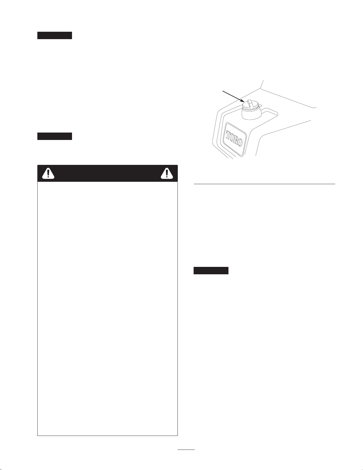
Fuel Shut-Off Valve
Close the fuel shut-off valve (Fig. 21), under the fuel tank,
when storing the machine.
1
Starting the Engine
Note: Inspect the areas beneath the mowers to be certain
they are clear of debris.
1. Unlock the mow lockout lever by pulling the pin
outward, rotating it clockwise, and inserting the end
into the rear hole in the bracket.
2. Sit on the seat, place the shift selector in Neutral, and
check the mow and lift pedals to be sure they are level
with one another.
3. Remove your foot from the traction pedal and make
sure the pedal is in the Neutral position.
4. Move the choke lever to the On position (only when
starting a cold engine) and the throttle lever to the half
throttle position.
5. Insert and rotate the ignition key clockwise until the
engine starts. After the engine starts, regulate the choke
to keep the engine running smoothly. As soon as
possible, open the choke by pulling it rearward to the
Off position. A warm engine requires little or no
choking.
6. Check the machine out with the following procedures
after the engine has started:
Figure 21
1. Fuel shut-off (under the fuel tank)
Break-in Period
Refer to the Engine Manual supplied with the machine for
oil change and maintenance procedures recommended
during the break-in period.
Only 8 hours of mowing operation is required for the
break-in period.
Since the first hours of operation are critical to future
dependability of the machine, monitor its functions and
performance closely so that minor difficulties, which could
lead to major problems, are noted and can be corrected.
Inspect the machine frequently during break-in for signs of
oil leakage, loose fasteners, or any other malfunction.
To ensure optimum performance of the brake system,
burnish (break-in) the brakes before using the machine. To
burnish the brakes, firmly apply the brakes and drive the
machine at mowing speed until the brakes are hot, as
indicated by their smell. An adjustment to the brakes may
be required after break-in; refer to Adjusting the Brakes,
page 32.
A. Move the throttle control to the Fast position and
momentarily engage the reels by depressing the
mow pedal. The cutting units should drop and all the
reels should turn.
B. Operate the lift pedal. The cutting reels should stop
and the cutting units should raise to the full
transport position.
Important Stop the engine. Check the lip of each
basket to be sure it is not in contact with the reel during
operation. Adjust the pull arms if contact is noted; refer
to Installing the Cutting Units.
C. Depress the brake pedal to keep the machine from
moving, and operate the traction pedal through the
forward and reverse positions.
D. Continue the above procedure for 1–2 minutes.
Neutralize the traction lever and mow and lift
pedals, lock the parking brake, and turn the engine
off.
E. Check for oil leaks. If oil leaks appear, check the
tightness of the hydraulic fittings. If oil leaks
continue to appear, contact your local Toro
Distributor for assistance and, if necessary,
replacement parts.
Important The motor or wheel seals may show
some trace of oil for a short period of time until the
machine break-in period has transpired.
20
Page 21

Note: Since the machine is new and the bearings and
reels are tight, it is necessary to use the Fast throttle
control position for this check. A fast throttle setting
may not be required after the break-in period.
Checking the Interlock System
2. Sit on the seat and engage the parking brake. Depress
the lift pedal fully and release it. Move the traction shift
selector to the #1 and #2 positions while trying to start
the engine in each position. The engine should not
crank, which means the traction switch on the valve
bank is operating correctly. If the engine did not crank,
proceed to step 3. If the engine cranked, contact your
local Toro Distributor for assistance.
Caution
If safety interlock switches are disconnected or
damaged the machine could operate unexpectedly
causing personal injury.
• Do not tamper with the interlock switches.
• Check the operation of the interlock switches
daily and replace any damaged switches before
operating the machine.
• Replace switches every two years regardless of
whether they are operating properly or not.
The purpose of the interlock system (Fig. 22) is to prevent
the engine from cranking or starting unless the traction shift
selector is in Neutral and the cutting units are disengaged.
In addition, the engine will stop when:
• the cutting units are engaged with the operator off of the
seat
• the traction shift selector is in the No. 1 or No. 2
position with the operator off of the seat or the parking
brake is engaged
3
1
2
Figure 22
1. Traction switch
2. Seat switch
Perform the following system checks daily to be sure the
interlock system is operating correctly:
1. Sit on the seat, engage the parking brake, and move the
shift selector to neutral. Remove your foot from the
traction pedal and make sure the pedal is in neutral.
Fully depress the lift pedal and release it. Try to start the
engine. The engine should crank and run, which means
the interlock system is operating correctly. If the engine
did crank, proceed to step 2. If the engine did not crank,
contact your local Toro Distributor for assistance.
3. Mow/lift switch
3. Sit on the seat and engage the parking brake. Fully
depress the lift pedal and release it. Move the traction
shift selector to neutral and try to start the engine. The
engine should start and continue to run, which means
the traction switch and mow/lift switch on the valve
bank are operating correctly; proceed to step 4. If the
engine cranked but did not start, the problem is not in
the interlock system. If engine did not crank, contact
your local Toro Distributor for assistance.
4. Sit on the seat, engage the parking brake, and move the
traction shift selector to neutral. Depress the mow pedal
and try to start the engine. The engine should not crank,
which means the mow/lift switch is operating correctly.
If the engine did not crank, proceed to step 5. If the
engine cranked, contact your local Toro Distributor for
assistance.
5. Sit on the seat and move the traction shift selector to
neutral. Fully depress the lift pedal and release it. Start
the engine and depress the mow pedal. Carefully rise
from the seat; the engine should stop. If the engine
stops, the interlock system is operating correctly. If the
engine does not stop, stop the engine and find the
problem before operating the machine again. If
assistance is required, contact your local Toro
Distributor.
6. Sit on the seat and move the traction shift selector to
Neutral. Fully depress the lift pedal and release it. Start
the engine and drive to an open area that is free of
debris and foreign objects. Keep all people, especially
children away from the front of the machine and out of
the area of operation. Move the shift selector to Neutral,
make sure the mow pedal is disengaged, set the throttle
control at half speed, and depress the brake pedal (do
not engage the parking brake button). While holding the
steering wheel, brace your feet on the foot deck and
brake pedal and move the shift selector to the #1
position. Carefully rise from the seat; the engine should
stop. If the engine stops, the interlock system is
operating correctly.
7. Repeat step 6 with the shift selector in the #2 position.
If the engine does not stop, stop the engine and find the
problem before operating the machine again. If
assistance is required, contact your local Toro
Distributor.
Note: The machine is equipped with an interlock switch on
the parking brake. The engine will stop if the traction shift
selector is in the #1 and #2 positions with the parking brake
engaged.
21
Page 22

Checking the Leak Detector
(Fig. 23–26)
The leak detector system is designed to assist in early
detection of hydraulic oil system leaks. If the oil level in
the main hydraulic reservoir, is lowered by 4 to 6 ounces,
the float switch in the tank will close. After a one second
delay, the alarm will sound, alerting the operator.
Expansion of oil, due to normal heating during machine
operation, will cause the oil to transfer into the auxiliary oil
reservoir. The oil is allowed to return to the main tank when
the ignition switch is turned off.
Filler Cap
Filler
Neck
Sight
Window
Solenoid Return
Valve
Open
Float
Switch Open
Raised
Hydraulic Oil
Tank
Overflow Tube
Fluid Level (cold)
No
Sound
Figure 23
Before Start (oil cold)
Fluid
Level
(warm)
Warning
Buzzer
Float Down
Switch Closed
Fluid Level Down 4 to 6 ounces
Figure 25
Leak Alert!
Checking the System Operation
1. With ignition switch in the On position, move the leak
detector switch rearward and hold. After the one-second
time delay elapses the alarm should sound.
2. Release the leak detector switch.
Checking the Leak Detector System
Operation
1. Move the ignition switch to the On position. Do not
start the engine.
Solenoid
Return
Valve
Closed
Float
Switch Open
Raised
Figure 24
Normal Operation (oil warm)
Fluid Level (warm)
No
Sound
2. Remove the hydraulic tank cap and strainer from the
neck of the tank.
3. Insert a clean rod or screwdriver into the tank neck and
gently push down on the switch float (Fig. 26). The
alarm should sound after the one-second delay.
Clean Rod
or Screwdriver
Warning
Buzzer
Press Down
on Switch
Float
Figure 26
22
Page 23

4. Release the float. The alarm should stop sounding.
5. Install the strainer screen and hydraulic tank cap. Move
the ignition switch to the Off position.
Preparing the Machine for
Mowing
To assist in aligning the machine for successive cutting
passes, it is suggested the following be done to the No. 2
and No. 3 cutting unit baskets:
1. Measure in approximately 5 in. (12.7 cm) from the
outer edge of each basket.
2. Either place a strip of white tape or paint a line onto
each basket paralleling the outer edge of each basket
(Fig. 27).
4
2
1
3
Important If you shift to the No. 2 position while
cutting greens, no increase in speed will result. However, a
sudden increase in speed will develop when you actuate the
lift pedal. For safety purposes, it is recommended that you
use only the No. 1 position for cutting greens and the No. 2
position for transport.
Before Mowing
Inspect the green for debris, remove the flag from the cup,
and determine the best direction to mow. Base the direction
to mow on the previous mowing direction. Always mow in
an alternate pattern from the previous mowing so that the
grass blades will be less apt to lay down and therefore be
difficult to trap between the reel blades and bedknife.
Mowing Procedures
1. Approach the green with the shift selector in the No. 1
position. Start on one edge of the green so that the
ribbon procedure of cutting may be used. This holds
compaction to a minimum and leaves a neat, attractive
pattern on the greens.
Important Shift to the No. 1 position when
approaching a green because the machine speed will
automatically be reduced when the cutting units are
engaged. Higher speed will resume when the cutting units
are disengaged.
Figure 27
1. Alignment strip
2. Approximately 5 in.
(12.7 cm)
3. Cut grass on right
4. Keep focal spot 6–10 ft.
(1.8–3 m) ahead of the
machine.
Training Period
Before mowing greens with the machine, it is
recommended that you find a clear area and practice
starting and stopping, raising and lowering the cutting
units, turning, etc. This training period will be beneficial to
the operator in gaining confidence in the performance of
the machine.
2. Actuate the mow pedal as the front edge of the grass
baskets cross the outer edge of the green. This
procedure drops the cutting units to the turf and starts
the reels.
Note: The No. 1 (rear) cutting unit reel will not start until
all the cutting units are on the ground and the No. 2 and
No. 3 cutting units are cutting.
Important Familiarize yourself with the fact that the
No. 1 cutting unit reel is delayed and therefore, you should
practice to try to gain the required timing necessary to
minimize the cleanup mowing operation.
3. Overlap a minimal amount with the previous cut on
return passes. To assist in maintaining a straight line
across the green and keep the machine an equal distance
from the edge of the previous cut, establish an
imaginary sight line approximately 6 to 10 ft. (1.8 to
3 m) ahead of the machine to the edge of the uncut
portion of the green (Fig. 27 and 28). Some find it
useful to include the outer edge of the steering wheel as
part of the sight line; i.e. keep the steering wheel edge
aligned with a point that is always kept the same
distance away from the front of the machine (Fig. 27
and 28).
23
Page 24

3
1. Alignment strip
2. Approximately 5 in.
(12.7 cm)
3. Cut grass on left
4
Figure 28
4. Keep focal spot 6–10 ft.
1
2
(1.8–3 m) ahead of the
machine.
6. If the leak detector alarm sounds while cutting on a
green, immediately raise the cutting units, drive directly
off of the green and stop the machine in an area away
from the green. Determine the cause of the alarm and
correct the problem.
Important Prolonged idling of the machine after heavy
use may cause a false alarm in the leak detector system, due
to oil contracting as it cools. If this occurs, turn the engine
off for approximately one minute, while the main hydraulic
tank is refilled from the auxiliary tank.
7. Finish cutting the green by mowing the outer periphery.
Be sure to change the direction of cutting from the
previous mowing. Always keep weather and turf
conditions in mind and be sure to change the direction
of mowing from the previous cutting. Replace the flag.
8. Empty the grass baskets of all clippings before
transporting to the next green. Heavy wet clippings
place an undue strain on the baskets and will add
unnecessary weight to the machine, thereby increasing
the load on the engine, hydraulic system, brakes, etc.
Leak Detector Operation
The leak detector alarm may sound for one of the following
reasons:
4. As the front of the baskets cross the edge of the green,
depress the lift pedal. This will stop the reels and lift the
cutting units. Timing of this procedure is important, so
the mowers do not cut into the fringe area. However, as
much of the green as possible should be cut to minimize
the amount of grass left to mow around the outer
periphery.
5. Cut down on operating time and ease lineup for the next
pass by momentarily turning the machine in the
opposite direction, then turning in the direction of the
uncut portion; i.e., if intending to turn right, first swing
slightly left, then right. This will assist in getting the
machine more quickly aligned for the next pass. Follow
the same procedure for turning in the opposite direction.
It is a good practice to try to make as short of a turn as
possible. However, turn in a wider arc during warmer
weather to minimize the possibility of bruising the turf.
Note: Due to the nature of the power steering system, the
steering wheel will not return to its original position after a
turn has been completed.
Important The machine should never be stopped on a
green with the cutting unit reels operating as damage to the
turf may result. Stopping on a wet green with the machine
may leave marks or indentations from the wheels.
• A leak of 4 to 6 ounces has occurred.
• The oil level in the main reservoir is reduced by 4 to
6 ounces due to contraction of the oil by cooling.
If the alarm sounds, it should be turned off as quickly as
possible and inspected for leaks. If the alarm sounds while
operating on a green it may be appropriate to drive off the
green first. The source of the leak should be determined
and repaired before continuing operation. If a leak is not
found, and a false leak is suspected, move the ignition
switch to the Off position and allow the machine to stand
for 1–2 minutes to allow the oil levels to stabilize. Then
start the machine and operate in a non-sensitive area to
confirm no leak exists.
False alarms, due to oil contraction, may be caused by
extended idling of the machine after normal operation. A
false alarm may also occur, if the machine is worked at a
reduced workload after an extended period of a heavier
workload. To avoid false alarms, turn the machine off
rather than idling for extended periods.
Transport Operation
Make sure the cutting units are in the full up position. Set
the shift selector in No. 2 if conditions will permit faster
ground speed. Shift to No. 1 and operate at slower ground
speeds in rough or hilly areas. Use the brakes to slow the
machine while going down steep hills to avoid loss of
control. Always approach rough areas at a reduced speed
24
Page 25

(shift selector in No. 1), and cross severe undulations
carefully. Familiarize yourself with the width of the
machine. Do not attempt to pass between objects that are
close together so that costly damage and down time can be
prevented.
Inspection and Cleanup After
damage to the seals and bearings. After cleaning, it is
recommended the machine be inspected for possible
hydraulic fluid leaks, damage or wear to hydraulic and
mechanical components, and the cutting units checked for
sharpness. Also, lubricate the mow and lift pedal and brake
shaft assembly with SAE 30 oil or spray lubricant to deter
corrosion and help keep the machine performing
satisfactorily during the next mowing operation.
Mowing
At the completion of the mowing operation, thoroughly
wash the machine with a garden hose without a nozzle so
excessive water pressure will not cause contamination and
Maintenance
Note: Determine the left and right side of the machine from the normal operating position.
Recommended Maintenance Schedule
Maintenance Service
Interval
After First 8 Hours
Every 50 Hours
Every 100 Hours
Every 200 Hours
Every 800 Hours
Every 2000 Hours or 2
Years (whichever
occurs first)
Maintenance Procedure
• Change the engine oil.
• Replace the engine oil filter.
• Check the battery fluid level.
• Check the battery cable connections.
• Service the air filter pre-cleaner.
• Lubricate all grease fittings.
• Change the engine oil.
• Replace the engine oil filter.
• Replace the air filter element.
• Check the reel bearing preload adjustment.
• Torque the wheel lug nuts.
• Replace the spark plugs.
• Replace the fuel filter.
• Check the engine RPM (idle and full throttle).
• Check the valve clearance.
• Replace moving hoses.
• Replace the safety switches.
• Drain/flush the fuel tank.
• Drain/flush the hydraulic tank.
• Replace the hydraulic oil and filter.
1
1
immediately after every washing, regardless of the interval listed
Important Refer to your engine operator’s manual for additional maintenance procedures.
25
Page 26

Daily Maintenance Checklist
Duplicate this page for routine use.
For the week of:
Maintenance Check Item
Check the safety interlock operation.
Check the instrument operation.
Check the leak detector alarm.
Check the brake operation.
Check the fuel level.
Check the engine oil level.
Clean the engine air cooling fins.
Inspect the air filter pre-cleaner.
Check any unusual engine noises.
Check the hydraulic hoses for damage.
Check for fluid leaks.
Check the tire pressure.
Check the reel-to-bedknife adjustment.
Check the height-of-cut adjustment.
Lubricate all grease fittings.
Lubricate the mow, lift, and brake
linkage.
Touch up damaged paint.
1
immediately after every washing, regardless of the interval listed
1
Mon. Tues. Wed. Thurs. Fri. Sat. Sun.
Notation for Areas of Concern
Inspection performed by:
Item Date Information
1
2
3
4
5
6
7
8
9
10
11
12
26
Page 27

Caution
If you leave the key in the ignition switch, someone could accidently start the engine and
seriously injure you or other bystanders.
Remove the key from the ignition and disconnect the wire from the spark plug before you do any
maintenance. Set the wire aside so that it does not accidentally contact the spark plug.
Lubrication
The traction unit has grease fittings that must be lubricated
regularly with No. 2 General Purpose Lithium-Base
Grease. If the machine is operated under normal conditions,
lubricate all bearings and bushings after every 50 hours of
operation.
The following traction unit bearings and bushings must be
lubricated:
• Rear wheel roller clutches and external ball bearing (1)
( 29)
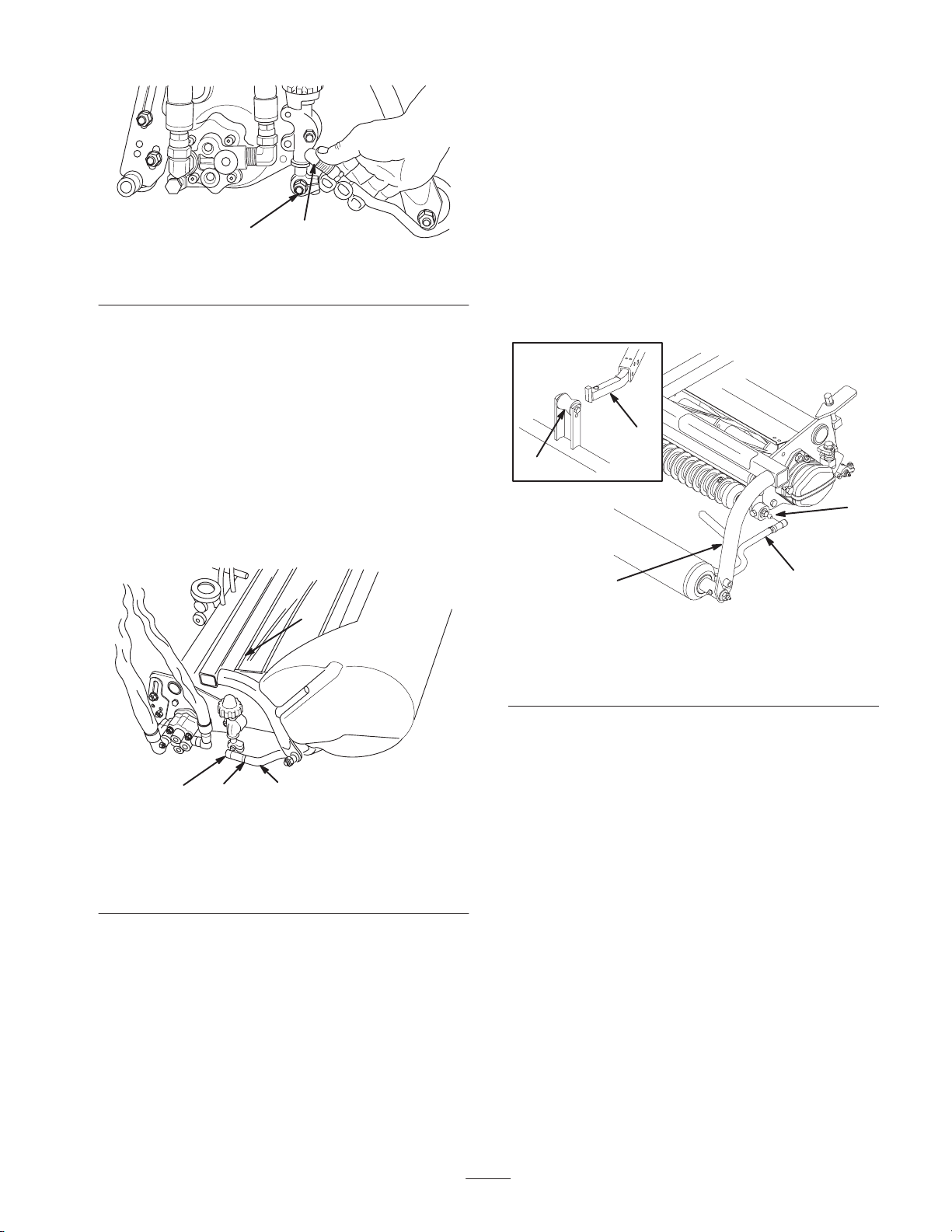
• Steering fork shaft (1) (Fig. 30)
• Lift arm pivot (3) and pivot hinge (3) (Fig. 31)
• Pull frame shaft and roller (12) (Fig. 32)
• Power steering cylinder (Fig. 33)
• Mow lift pivot (Fig. 34)
• Lift cylinders (3) (Fig. 35)
• Mow lockout lever (Fig. 36)
1. Wipe the grease fitting clean so foreign matter cannot
be forced into the bearing or bushing.
2. Pump grease into the bearing or bushing until the grease
is visible. Wipe up excess grease.
3. Apply grease to the reel motor spline shaft and onto the
lift arm when the cutting unit is removed for service.
4. Apply a few drops of SAE 30 engine oil or spray
lubricant (WD 40) to all pivot points daily after
cleaning.
Figure 29
Figure 30
27
Page 28

Figure 31
Figure 32
Figure 34
Figure 35
Figure 33
Figure 36
28
Page 29

Changing the Engine Oil and
Filter
Change the oil and filter after the first 8 hours of operation.
Thereafter, change the oil every 50 hours and the filter
every 100 hours.
1. Remove the drain plug (Fig. 37) and let oil flow into a
drain pan. When the oil stops, install the drain plug.
1
Figure 38
1. Air cleaner cover
2. Remove the wing nut securing the elements to the air
cleaner body.
2
1. Drain plug 2. Oil filter
2. Remove the oil filter (Fig. 37). Apply a light coat of
clean oil to the new filter gasket.
3. Screw the filter on by hand until the gasket contacts the
filter adapter, then tighten 1/2 to 3/4 turn further. Do
not overtighten.
4. Add oil to the crankcase; refer to Checking the Engine
Oil, page 14.
5. Dispose of the used oil properly.
1
Figure 37
Servicing the Air Cleaner
Service the air cleaner foam pre-cleaner after every 50
operating hours and the air cleaner cartridge after every 100
operating hours. More frequent cleaning is required when
operating in dusty or dirty conditions.
3. If the foam element is dirty, remove it from the paper
element (Fig. 39). Clean it thoroughly.
A. Wash the foam element in a solution of liquid soap
and warm water. Squeeze it to remove dirt, but do
not twist it because the foam may tear.
B. Dry it by wrapping it in a clean rag. Squeeze the rag
and foam element dry.
2
1
Figure 39
1. Foam element 2. Paper element
1. Release the locking clips and remove the air cleaner
cover (Fig. 38). Clean the cover thoroughly.
4. When servicing the foam element, check the condition
of the paper element. Clean it by gently tapping it on a
flat surface or replace it if needed.
5. Install the foam element, paper element, and air cleaner
cover.
Important Do not operate the engine without the air
cleaner element because extreme engine wear and damage
will likely result.
29
Page 30

Adjusting the Throttle Control
Adjusting the Carburetor and
Proper throttle operation is dependent upon proper
adjustment of the throttle control. Before adjusting the
carburetor, ensure that the throttle control is operating
properly.
1. Loosen the cable clamp screw securing the cable to the
engine (Fig. 40).
1
2
6
7
1. Throttle casing clamp
screw
2. Throttle cable
3. Swivel
4. Stop
5
Figure 40
5. Choke casing clamp
screw
6. Choke cable
7. Choke butterfly
4
3
Speed Control
Important Before the carburetor and speed control are
adjusted, the throttle and choke controls must be adjusted
properly.
Warning
The engine must be running during adjustment of
the carburetor and speed control. Contact with
moving parts or hot surfaces may cause personal
injury.
• Shift into neutral and engage the parking brake
before performing this procedure.
• Keep hands, feet, clothing, and other body parts
away from the cutting blades, rotating parts, the
muffler, and other hot surfaces.
1. Start the engine and let it run at half throttle for
approximately five minutes to warm up.
2. Move the throttle control to the Slow setting. Adjust the
idle stop screw counterclockwise until it no longer
contacts the throttle lever.
3. Bend the governed idle spring anchor tang (Fig. 41) to
attain an idle speed of 1450±50 RPM. Check the speed
with a tachometer.
2. Move the remote throttle control lever forward to the
Fast position.
3. Pull firmly on the throttle cable until the back of the
swivel contacts the stop (Fig. 40).
4. Tighten the cable clamp screw and check the engine
RPM setting.
High Idle: 2850 ± 50 RPM
Low Idle: 1650 ± 100 RPM
Adjusting the Choke Control
1. Loosen the cable clamp screw securing the cable to the
engine (Fig. 40).
2. Move the remote choke control lever forward to the
Closed position.
3. Pull firmly on the choke cable until the choke butterfly
is completely closed, then tighten the cable clamp screw
(Fig. 40).
2
1
Figure 41
Shown with Air Cleaner Removed
1. Governed idle spring
anchor tang
4. Adjust the idle stop screw clockwise until the idle speed
is 1650±100 RPM.
5. Move the throttle control to the Fast position. Bend the
high speed spring anchor tang (Fig. 41) to attain a high
speed of 2850±50 RPM.
2. High speed spring anchor
tang
30
Page 31

Replacing the Spark Plugs
Replacing the Fuel Filter
Replace the spark plugs after every 800 operating hours.
The recommended air gap is 0.030 in. (0.76 mm)
The correct spark plug to use is a Champion RC 12YC.
Note: The spark plug usually lasts a long time; however,
the plug should be removed and checked whenever the
engine malfunctions.
1. Clean the area around the spark plugs so foreign matter
cannot fall into the cylinder when the spark plug is
removed.
2. Pull the spark plug wires off of the spark plugs and
remove the plugs from the cylinder head.
3. Check the condition of the side electrode, center
electrode, and center electrode insulator to ensure that
there is no damage.
Important A cracked, fouled, dirty, or otherwise
malfunctioning spark plug must be replaced. Do not sand
blast, scrape, or clean electrodes by using a wire brush
because grit may eventually release from the plug and fall
into the cylinder. The result is usually a damaged engine.
4. Set the air gap between the center and side of the
electrodes at 0.030 in. (0.76 mm) (Fig. 42) Install the
correctly gapped spark plug w/gasket seal, and tighten
the plug to 200 in.-lb. (23 N⋅m). If a torque wrench is
not used, tighten the plug firmly.
An in-line filter is incorporated into the fuel line between
the fuel tank and carburetor (Fig. 43). Replace the filter
every 800 hours or sooner if the fuel flow is restricted. Be
sure the arrow on the filter is pointing away from the fuel
tank.
Danger
In certain conditions, gasoline is extremely
flammable and highly explosive. A fire or
explosion from gasoline can burn you and others
and can damage property.
• Drain gasoline from the fuel tank when the
engine is cold. Do this outdoors in an open area.
Wipe up any gasoline that spills.
• Never smoke when draining gasoline, and stay
away from an open flame or where a spark may
ignite the gasoline fumes.
1. Close the fuel shut off valve, loosen the hose clamp
(Fig. 43) on the carburetor side of filter and remove the
fuel line from the filter.
1
Figure 42
0.030 in.
(0.76 mm)
2
Figure 43
1. Fuel filter 2. Hose clamps
2. Place a drain pan under the filter, loosen the remaining
hose clamp, and remove the filter (Fig. 43).
3. Install the new filter with the arrow on the filter body
pointing away from the fuel tank.
31
Page 32

Changing the Hydraulic Oil and
Filter
Normally, change the hydraulic oil and filter after every
2000 operating hours. If the oil becomes contaminated,
contact your local Toro distributor because the system must
be flushed. Contaminated oil looks milky or black when
compared to clean oil.
3. Fill the replacement filter with Mobil DTE 15M
hydraulic fluid. Lubricate the sealing gasket, and hand
turn the filter until the gasket contacts the filter head.
Tighten the filter 3/4 turn further. The filter should now
be sealed.
4. Fill the large hydraulic tank and small auxiliary tank
with approximately 8.5 gallons of hydraulic oil; refer to
Checking the Hydraulic System, page 15.
1. Remove the drain plug from the reservoir (Fig. 44) and
let hydraulic oil flow into a drain pan. Reinstall and
tighten the plug when hydraulic oil stops draining.
1
Figure 44
1. Hydraulic reservoir drain plug
2. Clean the area around the filter mounting area (Fig. 45).
Place a drain pan under the filter and remove the filter.
5. Start the machine and run it at idle for 3 to 5 minutes to
circulate the fluid and remove any air trapped in the
system. Stop the machine and recheck the fluid level.
Note: If the leak detector alarm sounds, turn the key Off
and wait a few minutes for the oil level to equalize in the
tanks. Recheck the fluid level and add oil, if required.
6. Dispose of the used oil properly.
Checking the Hydraulic Lines
and Hoses
Warning
Hydraulic fluid escaping under pressure can
penetrate skin and cause injury.
• Make sure all hydraulic fluid hoses and lines are
in good condition and all hydraulic connections
and fittings are tight before applying pressure to
the hydraulic system.
• Keep your body and hands away from pin hole
leaks or nozzles that eject high pressure
hydraulic fluid.
• Use cardboard or paper to find hydraulic leaks.
• Safely relieve all pressure in the hydraulic
system before performing any work on the
hydraulic system.
• Get immediate medical help if fluid is injected
into skin.
1
1. Hydraulic filter
Figure 45
Check the hydraulic lines and hoses daily for leaks, kinked
lines, loose mounting supports, wear, loose fittings, weather
deterioration, and chemical deterioration. Make all
necessary repairs before operating.
Adjusting the Brakes
A brake adjustment rod is located on each side of the
machine so that the brakes can be equally adjusted. Adjust
the brakes as follows:
1. Transport the machine and depress the brake pedal; both
wheels should lock equally.
32
Page 33

Caution
Testing the brakes in a confined area where others
are present could cause injury.
Always check the brakes in a wide, open-spaced,
flat area which is free of other persons and
obstructions before and after adjustment.
Adjusting the Rear Camshaft
A camshaft misaligned with the valve bank may cause the
following:
• No increase in ground speed in the No. 2 (transport)
traction selection
• The mow pedal will not stay depressed (in detent)
without foot pressure.
2. If the brakes do not lock equally, disconnect the brake
rods by removing the cotter pin and clevis pin (Fig. 46).
1
3
2
4
m–5100
Figure 46
1. Clevis pin and cotter pin
2. Jam nut
3. Clevis
4. Brake shaft
3. Loosen the jam nut and adjust the clevis accordingly
(Fig. 46).
4. Assemble the clevis to the brake shaft (Fig. 46).
• Slow lift of the cutting units
• Slow or no drive to the cutting units
If one or more malfunctions occur, loosen the rear camshaft
mounting capscrews (Fig. 47) and relocate the cam shaft
until the condition is corrected. Tighten the capscrews.
Important Readjust the mow/lift switch and the lift and
mow pedal height when the camshaft adjustment is
completed.
2
1
5. Check the amount of free travel of the brake pedal when
the adjustment is completed. There should be 1/2 to
1 in. (13 to 26 mm) travel before the brake shoes make
contact with the brake drums. Readjust, if necessary, to
achieve this setting.
6. Transport the machine and depress the brake pedal; both
brakes should lock equally. Readjust, if necessary.
7. It is recommended that the brakes be burnished
annually; refer to Break-In Period, page 20.
Figure 47
1. Mounting capscrews 2. Cam blocks
33
Page 34

Adjusting the Lift and Mow
Pedal Height
To gain proper spool travel in the valve bank, adjust the lift
and mow pedals to equal heights as follows:
1. Place 1, 2 and 3 spools in neutral (center of travel) and
remove the transfer rod guard from the foot panel
(Fig. 48).
1
4. Install the clevis pin and cotter pin. Tighten the jam nut
and install the transfer rod guard.
5. Actuate the mow pedal by hand. Be sure the lift pivot
under the pedals clears the stop welded to the frame,
thereby allowing full spool travel.
Leveling the Lift and Mow
Pedals
If the lift and mow pedals are not level when they are in the
neutral position, an adjustment to the lift pivot is required.
1. Loosen the nut on the back side of the lift pivot
(Fig. 50).
2
1
Figure 48
1. Transfer rod guard
2. Loosen the jam nut securing the yoke on the front of the
long control rod. Remove the cotter pin and clevis pin.
3. Move the adjustment lever by hand to level the mow
and lift pedals and adjust the yoke on the control rod
until the hole in the yoke lines up with the adjustment
lever hole (Fig. 49).
4
2
1
3
m–5101
Figure 49
1. Jam nut
2. Yoke
3. Control rod
4. Adjustment lever
Figure 50
1. Lift pivot 2. Eccentric screw
2. Rotate the eccentric screw (Fig. 50) to raise or lower the
lift pivot spring, leveling the lift pivot and pedals.
3. While holding the screw, tighten the nut locking the
adjustment.
34
Page 35

Adjusting the Traction Pedal
Adjusting Cutting Unit Lift and
To check the forward and reverse operation of the traction
pedal, proceed as follows:
Adjusting Forward
1. Press the traction pedal fully forward until the No. 5
section valve spool is completely pulled out. The pedal
should contact the pedal stop (Fig. 51).
1
2
3
3/16 in.
(5 mm)
4
Figure 51
1. Fully forward
2. Pedal stop
If the pedal contacts the stop before the spool is
completely out, or if the pedal does not make contact
with the stop, an adjustment to the stop is necessary.
Proceed as follows:
2. Loosen the hex nut securing the threaded rod to the
frame. Turn the flange nut on the rod to raise or lower
the stop (rod) while checking the pedal. Retighten the
nut.
3. Reverse
4. Control rod
Drop
The cutting unit lift/drop circuit is equipped with a flow
control valve. This valve is preset at the factory at
approximately 3-1/2 turns open, but an adjustment may be
required to compensate for differences in hydraulic oil
temperatures, mowing speeds, etc. If an adjustment is
required, proceed as follows:
Note: Allow the hydraulic oil to reach full operating
temperature before adjusting the flow control valve.
1. Raise the seat and locate the flow control valve
mounted to the main control valve (Fig. 52).
1
Figure 52
1. Flow control valve
2. Loosen the jam nut retaining the adjusting knob on the
flow control. When loosening the jam nut, hold the
flow control knob to prevent it from rotating.
3. Rotate the knob 1/4 turn counterclockwise if the center
cutting unit is dropping too late or 1/4 turn clockwise if
the center cutting unit is dropping too early.
Adjusting Reverse
1. Press down on the rear of the traction pedal (reverse)
until the No. 5 section spool valve is completely pushed
in.
2. Check the distance between the bottom of the pedal and
footrest as shown in Figure 51. The distance shouId be
approximately 3/16 in. (5 mm). If the distance is greater
or less than 3/16 in. (5 mm), an adjustment to the
traction control rod is required. Proceed as follows:
A. Remove the jam nut and ball joint securing the
control rod (Fig. 51) to the traction shaft pivot.
B. Loosen the jam nuts securing the ball joints to the
control rod and adjust the ball joints and control rod
to attain the 3/16 in. (5 mm) dimension when
reinstalled.
4. After the desired setting has been achieved, hold the
knob to prevent any rotation and tighten the jam nut.
Adjusting the Lift Cylinders
To regulate the height of the front cutting units when in the
raised (transport) position, the front lift cylinders may be
adjusted.
1. Lower the cutting units to the ground.
2. Loosen the jam nut, on the clevis, of the cutting unit lift
cylinder that needs to be adjusted.
3. Disconnect the cylinder clevis from the lift arm.
4. Rotate the clevis until the desired height is attained.
5. Connect the cylinder clevis to the lift arm and tighten
the jam nut.
35
Page 36

Replacing the Seat Switch
Replacing the Traction Switch
1. Pivot the seat forward and secure it with the support
rod.
2. Remove the boot from the button end of the seat switch
(Fig. 53) and retain it for installation on the replacement
switch. Unplug the switch connectors.
3
1. Traction switch
2. Seat switch
1
Figure 53
3. Mow/lift switch
2
1. Pivot the seat forward and secure it with the support
rod.
2. Unplug the switch connectors from the traction switch
installed in the valve bank bonnet on the selector valve
section (Fig. 53).
3. Loosen the jam nut and unscrew the switch from the
mounting bracket.
4. Move the shift selector to Neutral.
5. Partially screw the new switch into the bonnet.
6. Connect a continuity tester or ohm meter to the switch
terminals and continue to turn the switch in until there
is continuity. Then rotate the switch in 1/2 turn (180
degrees).
7. Tighten the jam nut to 75 in.-lb. (8 N⋅m) against the
bonnet.
Important The switch threads will be damaged if the
jam nut is overtightened.
8. Connect a continuity tester or ohm meter to the switch
terminals and move the shift selector to the #1 and #2
positions. There should not be continuity when the shift
selector is in either of these positions. If there is
continuity, repeat steps 5 and 6.
3. Loosen the jam nut and unscrew the switch from the
mounting bracket.
4. Screw the new switch through the mounting bracket
until the switch button is about 1/16 in. (1.6 mm)
shorter than the top of the seat return spring pin. Install
the boot into the mount grooves.
5. Carefully release the seat to its normally down position,
but do not sit or apply force on the seat. There should
be a slight gap between the switch and the seat plate.
6. Lock the switch in place by tightening the jam nut to
75 in.-lb. (8 N⋅m) against the mounting bracket.
Important The switch threads will be damaged if the
jam nut is overtightened.
7. Connect a continuity tester or ohm meter to the switch
terminals. With the seat in the down position and no one
on the seat, the switch circuit should not have
continuity. If there is continuity, repeat steps 4–6. If
there is no continuity, proceed to step 8.
8. Sit on the seat. The seat switch should have continuity.
If there is no continuity, repeat steps 4–7. If there is
continuity, proceed to step 9.
9. Move the shift selector lever to Neutral and connect a
continuity tester or ohm meter to the switch terminals.
The switch should show continuity. This means the
switch is operating correctly.
10.Plug the switch connectors together.
Replacing the Mow/Lift Switch
Important The spool travel for the 1, 2 and 3 spools
must be correct before the mow/lift switch can be adjusted;
refer to Adjusting the Rear Camshaft, page 33.
1. Pivot the seat forward and secure it with the support
rod.
2. Unplug the switch connectors from the end of the
mow/lift switch installed in the valve bank bonnet
(Fig. 53).
3. Loosen the jam nut and unscrew the switch from the
valve bank bonnet.
4. While holding the lift pedal in the fully depressed
position (the valve bank spools are fully in) partially
screw the new switch into the bonnet.
9. Plug the switch connectors together.
36
Page 37

5. Connect a continuity tester or ohm meter across the
switch terminals and turn the switch in until continuity
occurs. Then rotate the switch in 1/2 turn (180 degrees)
and secure the jam nut to 75 in.-lb. (8 N⋅m) against the
bonnet.
Battery Care
Warning
Important The switch threads will be damaged if the
jam nut is overtightened.
6. Connect a continuity tester or ohm meter to the switch
terminals and depress the mow pedal. There should not
be continuity. If there is continuity, repeat step 4.
Proceed to step 7 if there is no continuity.
7. Depress the lift pedal and release it (neutral position).
The switch circuit should have continuity.
8. Plug the switch connectors together.
Adjusting the Traction Return
Linkage
If the shift selector lever does not return to Neutral or the
#1 position from the #2 position when the mow pedal is
engaged, an adjustment to the traction return linkage is
required.
1. Loosen the front jam nut securing the cable assembly to
the mow/lift control rod bracket (Fig. 54).
3
Battery posts, terminals, and related accessories
contain lead and lead compounds, chemicals
known to the State of California to cause cancer
and reproductive harm. Wash hands after
handling.
The battery electrolyte level must be properly maintained
and the top of the battery kept clean. Store the machine in a
cool place to prevent the battery from running down.
Check the electrolyte level every 50 operating hours or, if
machine is in storage, every 30 days.
Danger
Battery electrolyte contains sulfuric acid which is a
deadly poison and causes severe burns.
• Do not drink electrolyte and avoid contact with
skin, eyes or clothing. Wear safety glasses to
shield your eyes and rubber gloves to protect
your hands.
• Fill the battery where clean water is always
available for flushing the skin.
2
1
Figure 54
1. Cable assembly
2. Mow/lift control rod
bracket
2. Move the shift lever to the #1 position.
3. While holding the mow/lift control rod in the rear
position, tighten the rear locknut to remove almost all of
the slack from the cable assembly (Fig. 54). Do not
over-tension the cable.
4. Tighten the front jam nut to lock the adjustment.
3. Mow/lift control rod
Maintain the cell level with distilled or demineralized
water. Do not fill the cells above the bottom of the split ring
inside each cell.
Keep the top of the battery clean by washing it periodically
with a brush dipped in ammonia or bicarbonate of soda
solution. Flush the top surface with water after cleaning it.
Do not remove the fill caps while cleaning the battery.
The battery cables must be tight on the terminals to provide
good electrical contact.
Warning
Incorrect battery cable routing could damage the
tractor and cables causing sparks. Sparks can
cause the battery gasses to explode, resulting in
personal injury.
• Always disconnect the negative (black) battery
cable before disconnecting the positive (red)
cable.
• Always connect the positive (red) battery cable
before connecting the negative (black) cable.
5. Check the operation and readjust as required.
37
Page 38

If corrosion occurs at the terminals, disconnect the cables,
negative (–) cable first, and scrape the clamps and terminals
separately. Reconnect the cables, positive (+) cable first,
and coat the terminals with petroleum jelly.
Storage
If you wish to store the machine for a long period of time,
the following steps should be performed prior to storage:
1. Remove accumulations of dirt and old grass clippings.
Sharpen the reels and bedknives, if necessary; refer to
the Cutting Unit Operator’s Manual. Use a rust
preventive on bedknives and reel blades. Grease and oil
all lubrication points; refer to Lubrication, page 27.
2. Block up the wheels to remove any weight on the tires.
3. Drain and replace the hydraulic fluid and filter and
inspect the hydraulic lines and fittings. Replace, if
necessary; refer to Changing the Hydraulic Oil and
Filter, page 32 and Checking the Hydraulic Lines and
Hoses, page 32.
4. All fuel should be removed from the fuel tank. Run the
engine until it stops from lack of fuel. The small
amount of fuel that remains in the bottom of the tank
should be removed by absorbing it with a clean dry
cloth. Replace the fuel filter; refer to Replacing the Fuel
Filter, page 31.
5. While the engine is still warm, drain the oil from the
crankcase. Refill it with fresh oil; refer to Changing the
Engine Oil and Filter, page 29.
6. Remove the spark plugs, pour one ounce of SAE 30 oil
into the cylinders, and crank slowly to distribute the oil.
Replace the spark plugs; refer to Replacing the Spark
Plugs, page 31.
7. Clean dirt and chaff from the cylinder, cylinder head
fins, and blower housing.
8. Remove the battery and charge it fully. Either store it on
the shelf or on the machine. Leave the cables
disconnected if it is stored on the machine. Store the
battery in a cool atmosphere to avoid quick
deterioration of the charge in the battery.
9. If possible, store the machine in a warm, dry location.
38
Page 39

Electrical Schematic
TO THE LIGHTS
(OPTIONAL)
ALARM
TIMER
GY
W
(+)
(–)
SOLENOID VALVE
AB
STOP –––– NONE
RUN –––– B+I+A; X+Y
START ––– B+I+S
RED
R
PU PURPLE
W WHITE
BK
Y
X
S
I
IGNITION SW
Y YELLOW
RUN STARTOFF
SPLICESP
GY
IB
LEAK DETECTOR
BN
R
(CLOSED WHEN THERE’S
A HYDRAULIC OIL LEAK)
LIGHT/TEST SW.
BU
BU
OR
Y
S
A
X
W
10A
SP
OR
(+)
BU
(+)
VOLT
VIO
SP
FL
FL
HR
(–)
VOLT METER
(–)
HR METER
W
STARTER SOLENOID
BK
BU
BK
VIO
87a
87
86
KILL RELAY
85
30
BK
GY
MOW SW.
(CLOSED WHEN OFF)
GN
D1
Y
NEUTRAL SW.
BN
(CLOSED IN NEUTRAL)
W
VIO
BK
SEAT SW.
(CLOSED WHEN OCCUPIED)
GY
BKVIO
85
30
87
86
87a
D2
BN
PARKING BRAKE KILL RELAY
W
(IN OFF POSITION)
PARKING BRAKE
BLACK
BROWN
BKBNBU
BLUE
FUSIBLE LINK
FL
GY GRAY
OR ORANGE
STARTER
ALTERNATOR
ENGINE
FUEL SOLENOID
MAGNETO
BATTERY
(+)
(–)
ENGINE GNDFRAME GND
T–2804
39
Page 40

Hydraulic Schematic
AUXILIARY
TANK BREATHER
40 MICRON
10.3 CU. IN/REV
(169 CU. CM/REV)
WHEEL DRIVE MOTORS
LH RH
HYDRAULIC TANK
NORMALLY OPEN
SOLENOID VALVE
FWD
2ND
OIL FILTER
10 MICRON
1ST
LEVEL
N
SENSOR
N
HYDRAULIC
TANK
VALVE BANK
REV
SAFETY INTERLOCK
SWITCH
1850 PSI
(130 KG/SQ CM)
3
.33 IN /REV
(5.4 CU CM/REV)
PUMP
2900 RPM MAX
3
3
.18 IN /REV
(2.9 CU CM/REV)
850 PSI
(60 KG/SQ CM)
.33 IN /REV
(5.4 CU CM/REV)
.43 CU. IN/REV.
REEL MOTORS
3
.58 IN /REV
9.5 CU CM /REV
2000 PSI
(141 KG/SQ CM)
SAFETY
INTERLOCK
SWITCH
2000 PSI
(141 KG/SQ CM)
4.5 CU. IN/REV.
(75 CU. CM/REV)
STEERING CONTROL VALVE
2000 PSI
(141 KG/SQ CM)
CENTER
(7 CU. CM/REV.)
RH
CENTER
RH
ONE WAY
ORIFICE
LIFT CYLINDERS
ADJUSTABLE
FLOW
RESTRICTOR
TP
LH
LH
STEERING CYLINDER
LR
T–1302
40
Page 41

Troubleshooting
g
g
y
Problem Possible Causes Corrective Action
Engine:
The engine loses power.
The engine will not start.
Hydraulic:
There is no ground speed increase in
the #2 selection.
In the hydraulic system there is no #1
or reverse traction speed. The #2
speed is normal.
1. The fuel tank is empty. 1. Fill the fuel tank.
2. A fuel line is clogged or there is
debris in the fuel tank.
3. The fuel filter is clogged. 3. Replace the filter.
4. The oil level in the crankcase is
low.
5. The oil in the crankcase is
incorrect.
6. Carburetor fuel solenoid 6. Check the solenoid and wiring.
7. The throttle cable is set incorrectly. 7. Repair as necessary.
8. The choke is closed. 8. Readjust the choke.
9. The air cleaner element is plugged. 9. Replace the element and service it
10.The carburetor malfunctions. 10. Repair as necessary.
11. The ignition malfunctions. 11. Repair as necessary.
12.The cooling fins are plugged with
debris or the engine is overheating.
13.The engine has an internal
malfunction.
14.The pump coupling is loose. 14.Repair or replace the coupling.
15.The hydraulic system is
malfunctioning.
1. The ignition system is faulty. 1. Repair as necessary.
2. The fuel tank is empty. 2. Fill the fuel tank.
3. The starter system is
malfunctioning.
4. Carburetor fuel solenoid 4. Check the solenoid and wiring.
1. The control lever is misadjusted. 1. Adjust the control lever.
2. The rear camshaft is misadjusted. 2. Adjust it by moving the right end or
3. The mow/lift linkage is binding or
there is a broken lift pivot spring.
4. There are wrong detent parts in the
#4 spool.
5. The #2 or #3 spool relief valves are
stuck open. (The reel drive RPM
will also be low on the #1 or #3
cutting unit).
1. The disc seal between the #3 and
#4 valve sections is damaged or
missing.
2. The poppet inside the #4 spool is
stuck open or off its seat.
2. Clean the fuel tank. Use clean
gasoline.
4. Add oil to the proper level. Check
the level more frequently.
5. Replace it with the correct oil.
more frequently.
12.Clean the fins. Repair the engine
as necessary.
13.Repair as necessary.
15.Refer to hydraulic troubleshooting
below.
3. Check the connections, solenoid,
starter motor, and ignition switch.
the rear camshaft forward or the
left end rearward.
3. Lubricate or repair the machine.
4. Remove the valve bank and repair
the #4 spool assembly.
5. Remove and repair or replace the
relief cartridge.
1. Remove the valve bank and
replace the disc seal.
2. Remove the valve bank and repair
the #4 spool section.
41
Page 42

Problem Corrective ActionPossible Causes
or reverse traction s eed. The #2
gy
In the hydraulic system there is no #1
or reverse traction speed. The #2
speed is normal. (continued)
There is no traction or it is slow in all
selections.
There is no traction or it is slow in all
selections and the reels are affected.
The shift lever is binding. 1. The #4 spool detent assembly is
All three cutting units raise and lower
too slowly.
The center (#1) cutting unit is dropping
too late or too early.
The front cutting units are too high or
too low when they are in the raised
(transport) position.
The cutting units lift too slowly.
The center cutting unit (#1) reel
operates in the raised position.
3. The traction relief cartridge in the
#4 spool section is open.
4. A traction motor lacks efficiency.
There is fluid leaking past the
internal gears.
5. The hydraulic pump lacks
efficiency. There is fluid leaking
past the internal gears.
1. The brakes are dragging. 1. Determine the cause and repair it.
2. The o-ring seals around the
traction relief cartridge or inlet
sleeve in the #4 spool valve are
faulty. Fluid is leaking by to the
tank.
3. A traction motor(s) is worn or
weak.
4. The pump is excessively worn. 4. Test to verify. Repair or replace the
5. The traction relief in the #4 spool
valve is open.
1. The oil level in the reservoir is low. 1. Add oil to the proper level.
2. The shift lever bracket is loose. 2. Adjust and tighten the shift lever.
3. The rear camshaft is misadjusted. 3. Adjust the camshaft.
4. The engine lacks power. 4. Repair as necessary.
lacking lubrication.
1. The lift cylinder and linkages are
binding due to lack of lubrication.
1. The flow control valve is
misadjusted.
1. The front lift cylinders are
misadjusted.
1. The rear camshaft is misadjusted. 1. Adjust the camshaft.
2. The #1 spool travel is restricted by
the mow/lift switch.
3. The lift check poppet in the #1
spool section is stuck partially
closed.
1. The rear camshaft is misadjusted.
The #3 spool is too far out of the
body.
2. The brazed tube assembly on the
#3 spool section is restricted.
3. The valve return port between the
#3 spool section and the right-hand
cover is restricted.
3. Remove the relief cartridge. Repair
or replace it.
4. Test to identify the faulty motor.
Repair or replace the motor.
5. Test to verify a diagnosis. Repair or
replace the pump.
2. Remove the relief and inlet sleeve.
Replace the o-rings.
3. Test to verify. Repair or replace the
motor(s).
pump.
5. Remove, repair, or replace it.
1. Remove the valve bank.
Disassemble the detent assembly
and repair it.
1. Lubricate more frequently.
1. Adjust the valve.
1. Adjust the cylinders.
2. Adjust the switch.
3. Remove the lift check and repair or
replace it.
1. Adjusted the camshaft.
2. Remove the restriction.
3. Disassembly the cover and remove
the restriction.
42
Page 43

Problem Corrective ActionPossible Causes
there is no reel driven action.
The cutting units drop during transport
(between greens).
The cutting units drop while the
machine is stored (overnight).
One or more cutting units are slow or
there is no reel driven action.
The reel drive pressure lines pulsate
during operation.
The leak detector alarm sounds.
1. A lift cylinder is leaking internally. 1. Raise the units and block them up.
Remove the lines from the brazed
tube and remove the blocks. The
line that leaks fluid is attached to
the bad cylinder. Repair the
cylinder.
2. The lift check plug seals in the #1
spool body are damaged.
3. A detent stud is loose in the #2
spool.
4. The #1 spool is loose in the valve
body and fluid is bypassing.
1. This is a normal condition. 1. No repair is necessary.
1. The bedknife to reel adjustment is
too tight.
2. The reel bearings are tight. 2. Repair as necessary.
3. The rear camshaft is misadjusted. 3. Adjust the camshaft.
4. The poppet in a relief cartridge is
off seat.
5. An improper suction line(s) is
installed. The line collapsed.
6. A line fitting has a blockage. 6. Repair as necessary.
7. A motor is excessively worn. 7. Test to verify. Repair or replace the
8. The #1 cutting unit has slow reel
RPM.
9. The pump is excessively worn. 9. Text to verify. Repair or replace the
10.A spool is loose in the valve body.
Fluid is leaking past the spool.
11. A steel pressure line is damaged
and flow is restricted (front cutting
units only).
12.The fluid level is low enough to
affect the total machine
performance.
1. This is a normal condition. It will
vary from line to line.
1. The system is leaking oil. 1. Repair as necessary.
2. The fluid level is low. 2. Add fluid.
3. The oil is contracting as it cools
due to prolonged idling after heavy
use.
4. The solenoid valve fails to open. 4. Repair as necessary.
2. Remove the lift check plugs.
Replace the o-ring assemblies.
3. Remove the adjustment cap from
the #2 spool bonnet. Tighten the
stud with a screwdriver.
4. Replace the spool valve assembly.
1. Adjust per the cutting unit
operator’s manual
4. Remove and repair or replace the
relief cartridge.
5. Remove the suction line and
replace with genuine Toro parts.
motor.
8. Check the lift cylinders for internal
leakage. Repair or replace the
cylinder.
pump.
10.Replace the spool valve assembly.
11. Replace the line.
12.Add fluid.
1. No repair is necessary.
3. Turn the engine off for
approximately one minute while
the main hydraulic tank is refilled
from the auxiliary tank.
43
Page 44

Problem Corrective ActionPossible Causes
y
The leak detector alarm fails to sound.
The mow pedal will not stay down
unless it is held down with your foot
(the #2 spool is not in Detent).
Electrical:
The engine starts (but should not)
when the shift selector is in gear.
The engine starts (but should not)
when the mow pedal is depressed and
the reels are engaged.
The engine starts (but should not)
when the operator is not on the seat.
The engine fails to crank, regardless of
the shift selector or mow pedal
position.
The engine cranks but does not start
when the shift selector and mow pedal
are in neutral.
1. The leak detector float switch is not
operating properly.
2. The time delay is operating
incorrectly.
3. The alarm is not operating. 3. Replace the alarm.
4. There is an electrical malfunction. 4. Test to verify. Repair as necessary.
5. The solenoid valve fails to close. 5. Repair as necessary.
1. The rear camshaft is misadjusted. 1. Adjust the camshaft.
2. The #2 spool detent is
malfunctioning.
1. The traction switch is adjusted
incorrectly or is damaged.
1. The mow/lift switch is adjusted
incorrectly or is damaged.
1. The seat switch is adjusted
incorrectly or is damaged.
1. The mow/lift switch, traction switch,
and/or seat switch are adjusted
incorrectly or are damaged.
2. The battery terminals are corroded. 2. Clean the terminals.
3. The mow/lift or traction switch
wires are loose.
4. The battery is dead. 4. Charge or replace the battery.
5. A solenoid is damaged. 5. Replace the solenoid.
6. The ignition switch is damaged. 6. Replace the ignition switch.
7. The starter is damaged. 7. Replace or repair the starter.
8. The engine is seized. 8. Repair the engine.
9. The key switch, voltmeter, or
solenoid wires are loose.
10.The operator is not on the seat. 10. Sit on the seat.
1. The cause of this problem is
unrelated to the interlock wiring
system.
2. The rear camshaft is misadjusted. 2. Adjust the camshaft.
3. The engine or rectifier plug is
loose.
4. The “I” terminal wire of key switch
is loose.
5. There is engine trouble or the fuel
tank is empty.
6. The parking brake kill relay is
damaged.
1. Check the operation of the leak
detector float switch and wiring.
2. Replace the time delay.
2. Remove and repair it.
1. Refer to Replacing the Traction
Switch.
1. Refer to Replacing the Mow/Lift
Switch.
1. Refer to Replacing the Seat Switch
1. Refer to Replacing the Traction
Switch, Replacing the Mow/Lift
Switch, and/or Replacing the Seat
Switch.
3. Check the wires and connect them
properly.
9. Connect the wires.
1. All interlock switches are okay.
Proceed to next cause.
3. Connect the wire.
4. Connect the wire.
5. Determine the problem and correct
it.
6. Replace the relay.
44
Page 45

Problem Corrective ActionPossible Causes
gg ) y g
when sitting on the seat and the shift
()yg
ignition key is rotated to the Off
yg
The engine does not stop when the
mow pedal is depressed (the reels are
engaged) as you get off of the seat.
The engine does not stop when the
shift selector is in gear as you get off
of the seat.
The engine does not continue to run
when sitting on the seat and the shift
selector is placed in gear or the mow
pedal is depressed.
The engine stops regardless of the
shift selector or mow pedal position
(even if both are in Neutral) as you get
off of the seat.
The engine seems to “cut out” too
much during transport. (Some cut out
is normal.)
The engine does not stop when the
ignition key is rotated to the Off
position.
The battery does not charge.
1. The mow/lift or seat switch is
adjusted incorrectly or is damaged.
2. The seat return pin spring is
broken, missing, or jammed down.
3. The seat pivot fails to rotate freely. 3. Loosen and lubricate the seat pivot
1. The traction or seat switch is
adjusted incorrectly or is damaged.
2. The seat return pin spring is
broken, missing, or jammed down.
3. The seat pivot fails to rotate freely. 3. Loosen and lubricate the seat pivot
1. The seat switch is adjusted
incorrectly or is damaged.
2. The seat return pin spring is
jammed in the up position.
3. The parking brake switch wires are
loose.
4. The parking brake switch wires are
damaged.
1. The mow/lift switch and/or traction
switch are adjusted incorrectly or
are damaged.
2. The mow/lift and/or traction switch
wires are loose.
3. The traction switch extension plug
wires are loose.
4. The “B” terminal wire of the key
switch is loose.
1. The seat if lifting off of the seat
switch button too easily.
1. The ignition switch connection is
loose.
2. The ignition switch is damaged. 2. Replace the ignition switch.
3. The wires in the connector have
shorted.
4. The engine timing or carburetor
adjustment is incorrect.
1. A fuse is blown or missing. 1. Install a new fuse.
2. The electrical system has a loose
wire.
3. The regulator or engine charging
circuit is damaged.
1. Refer to Replacing the Mow/Lift
Switch or Replacing the Seat
Switch.
2. Replace, loosen, and lubricate the
parts so that the pin operates
freely.
pin to ensure free movement.
1. Refer to Replacing the Traction
Switch or Replacing the Seat
Switch.
2. Replace, loosen, and lubricate the
parts sp that the pin operates
freely.
pin the ensure free movement.
1. Refer to Replacing the Seat
Switch.
2. Loosen and lubricate the jammed
parts so that the pin operates
freely. Replace the spring if it is
damaged.
3. Connect the wires.
4. Replace the switch.
1. Refer to Replacing the Mow/Lift
Switch and Replacing the Traction
Switch.
2. Connect the wires.
3. Connect the wires.
4. Connect the wires.
1. Adjust the seat switch or instruct
the operator to sit back in the seat
during transport.
1. Push the connector onto the
ignition switch terminals.
3. Repair the affected wires.
4. Adjust the carburetor or engine
timing.
2. Check all connections and make
all necessary repairs.
3. Install a new regulator or repair the
engine charging circuit.
45
Page 46

Problem Corrective ActionPossible Causes
are sitting on the seat and the shift
The engine does not stop when you
are sitting on the seat and the shift
selector is in gear with the parking
brake on.
1. The connector is off of the parking
brake kill relay.
2. The parking brake switch is
damaged.
3. A diode is damaged. 3. Replace the diode.
1. Push the connector onto the relay.
2. Replace the switch.
46
Page 47

47
Page 48

The Toro General Commercial Products Warranty
A Two-Year Limited Warranty
Conditions and Products Covered
The Toro Company and its affiliate, Toro Warranty Company,
pursuant to an a g r eement between them, jointly warrant your 1996
or newer Toro Commercial Product (“Product”) purchased after
January 1, 1997, to be free from defects in materials or
workmanship for tw o years or 1500 operational hours*, whichever
occurs first. Where a warrantable condition exists, we will repair the
Product at no cost to you including diagnosis, labor, parts, and
transportation. This warranty begins on the date the Product is
delivered to the original retail purchaser.
* Product equipped with hour meter
Instructions for Obtaining Warranty Service
You are responsible for notifying the Commercial Products
Distributor or Authorized Commercial Products Dealer from whom
you purchased the Product as soon as you believe a warrantable
condition exists.
If you need help locating a Commercial Products Distributor or
Authorized Dealer, or if you have questions regarding your
warranty rights or responsibilities, you may contact us at:
Toro Commercial Products Service Department
Toro Warranty Company
8111 Lyndale Avenue South
Bloomington, MN 55420-1196
952-888-8801 or 800-982-2740
E-mail: commercial.service@toro.com
Owner Responsibilities
As the Product owner, you are responsible for required maintenance and adjustments stated in your operator’s manual. Failure
to perform required maintenance and adjustments can be grounds
for disallowing a warranty claim.
Items and Conditions Not Covered
Not all product failures or malfunctions that occur during the
warranty period are defects in materials or workmanship. This
express warranty does not cover the following:
• Product failures which result from the use of non-Toro
replacement parts, or from installation and use of add-on,
modified, or unapproved accessories
• Product failures which result from failure to perform required
maintenance and/or adjustments
• Product failures which result from operating the Product in an
abusive, negligent or reckless manner
• Parts subject to consumption through use unless found to be
defective. Examples of parts which are consumed, or used up,
during normal Product operation include, but are not limited to,
blades, reels, bedknives, tines, spark plugs, castor wheels,
tires, filters, belts, etc.
• Failures caused by outside influence. Items considered to be
outside influence include, but are not limited to, weather,
storage practices, contamination, use of unapproved coolants,
lubricants, additives, or chemicals, etc.
• Normal “wear and tear” items. Normal “wear and tear” includes,
but is not limited to, damage to seats due to wear or abrasion,
worn painted surfaces, scratched decals or windows, etc.
Parts
Parts scheduled for replacement as required maintenance are
warranted for the period of time up to the scheduled replacement
time for that part.
Parts replaced under this warranty become the property of Toro.
T oro will make the final decision whether to repair any existing part
or assembly or replace it. Toro may use factory remanufactured
parts rather than new parts for some warranty repairs.
General Conditions
Repair by an Authorized Toro Distributor or Dealer is your sole
remedy under this warranty.
Neither The Toro Company nor Toro Warranty Company is
liable for indirect, incidental or consequential damages in
connection with t h e use of the Toro Products covered by this
warranty, including any cost or expense of providing substitute equipment or service during reasonable periods of
malfunction or non-use pending completion of repairs under
this warranty. Except for the Emissions warranty referenced
below, if applicable, there is no other express warranty. All
implied warranties of merchantability and fitness for use are
limited to the duration of this express warranty.
Some states do not allow exclusions of incidental or consequential
damages, or limitations on how long an implied warranty lasts, so
the above exclusions and limitations may not apply to you.
This warranty gives you specific legal rights, and you may also
have other rights which vary from state to state.
Note regarding engine warranty: The Emissions Control System
on your Product may be covered by a separate warranty meeting
requirements established by the U.S. Environmental Protection
Agency (EPA) and/or the California Air Resources Board (CARB).
The hour limitations set forth above do not apply to the Emissions
Control System Warranty. Refer to the Engine Emission Control
Warranty Statement printed in your operator’s manual or contained in the engine manufacturer’s documentation for details.
Countries Other than the United States or Canada
Customers who have purchased Toro products exported from the United States or Canada should contact their Toro Distributor (Dealer)
to obtain guarantee policies for your country, province, or state. If for any reason you are dissatisfied with your Distributor’s service or
have difficulty obtaining guarantee information, contact the Toro importer. I f all other remedies fail, you may contact us at Toro Warranty
Company.
Part No. 374-0031 Rev. –
 Loading...