

Page 1

FormNo.3362-974RevA
Greensmaster
®
30502-Wheel
DriveTractionUnit
ModelNo.04351—SerialNo.290000001andUp
ToregisteryourproductordownloadanOperator'sManualorPartsCatalogatnocharge,gotowww.T oro.com.OriginalInstructions(EN)
Page 2
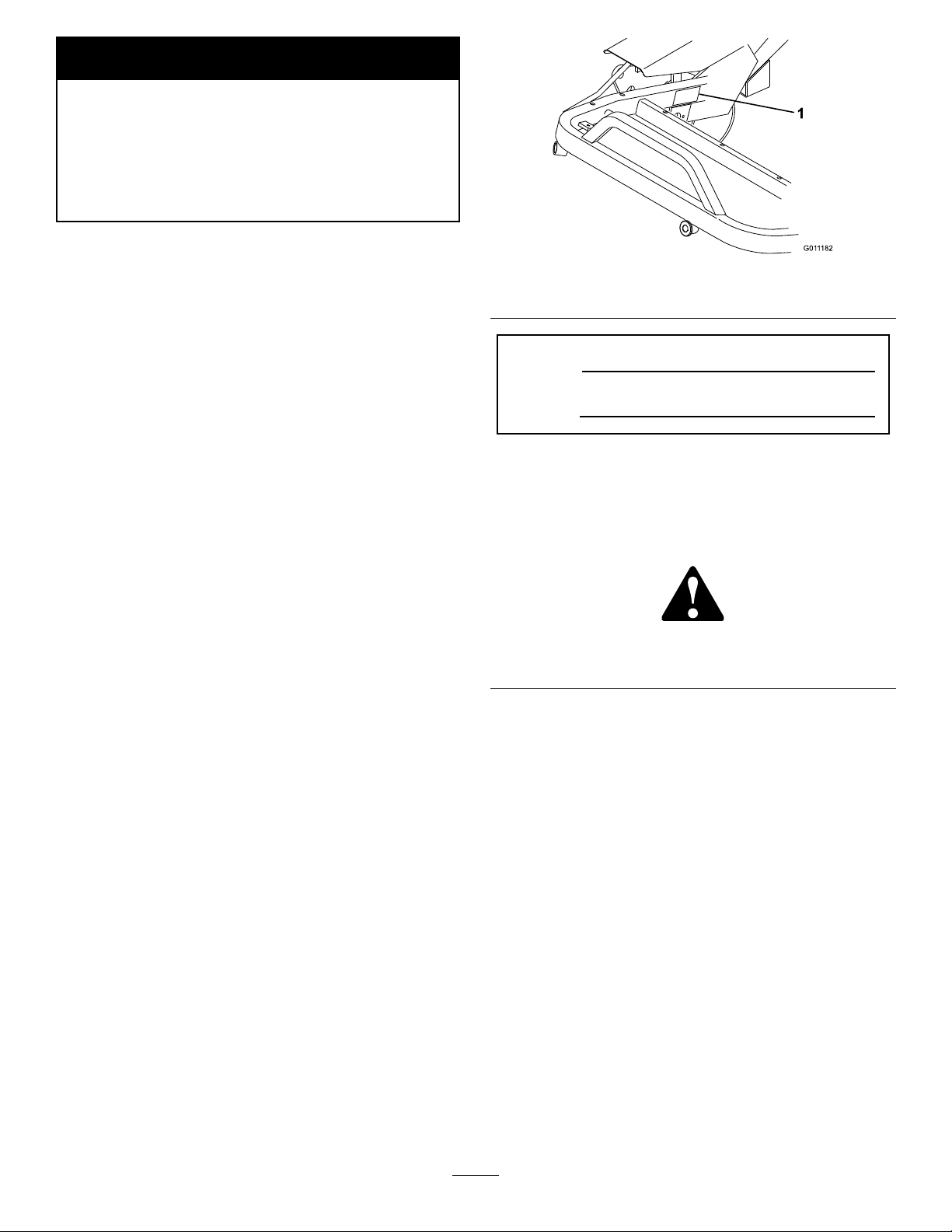
WARNING
G011182
1
CALIFORNIA
Proposition65Warning
Theengineexhaustfromthisproduct
containschemicalsknowntotheStateof
Californiatocausecancer,birthdefects,
orotherreproductiveharm.
Important:Thisengineisnotequippedwitha
sparkarrestermufer.ItisaviolationofCalifornia
PublicResourceCodeSection4442touseoroperate
theengineonanyforest-covered,brush-covered,or
grass-coveredland.Otherstatesorfederalareas
mayhavesimilarlaws.
ThissparkignitionsystemcomplieswithCanadian
ICES-002.
Theenclosed
Engine Owner’ s Man ual
issupplied
forinformationregardingtheUSEnvironmental
ProtectionAgency(EPA)andtheCalifornia
EmissionControlRegulationofemissionsystems,
maintenance,andwarranty.Replacementsmaybe
orderedthroughtheenginemanufacturer.
Introduction
Readthisinformationcarefullytolearnhowtooperate
andmaintainyourproductproperlyandtoavoidinjury
andproductdamage.Youareresponsibleforoperating
theproductproperlyandsafely.
YoumaycontactTorodirectlyatwww .Toro.comfor
productandaccessoryinformation,helpndinga
dealer,ortoregisteryourproduct.
Figure1
1.Modelandserialnumberlocation
ModelNo.
SerialNo.
Thismanualidentiespotentialhazardsandhas
safetymessagesidentiedbythesafetyalertsymbol
(Figure2),whichsignalsahazardthatmaycauseserious
injuryordeathifyoudonotfollowtherecommended
precautions.
Figure2
1.Safetyalertsymbol
Thismanualalsouses2wordstohighlightinformation.
Importantcallsattentiontospecialmechanical
informationandNoteemphasizesgeneralinformation
worthyofspecialattention.
Wheneveryouneedservice,genuineToroparts,or
additionalinformation,contactanAuthorizedService
DealerorToroCustomerServiceandhavethemodel
andserialnumbersofyourproductready.
Figure1
identiesthelocationofthemodelandserialnumbers
ontheproduct.Writethenumbersinthespace
provided.
©2009—TheT oro®Company
8111LyndaleAvenueSouth
Bloomington,MN55420
Contactusatwww.Toro.com.
2
PrintedintheUSA.
AllRightsReserved
Page 3

Contents
Introduction.................................................................2
Safety...........................................................................4
SafeOperatingPractices.......................................4
ToroMowerSafety...............................................5
SoundPressure.....................................................6
SoundPower........................................................6
Vibration..............................................................6
SafetyandInstructionalDecals.............................7
Setup..........................................................................10
1ActivatingandChargingtheBattery..................11
2MountingtheSeat............................................12
3SecuringtheSteeringArm................................12
4InstallingtheCover..........................................12
5InstallingtheBattery........................................13
6InstallingtheCuttingUnits(ForCutting
UnitModels04610and04611Only)...............14
7AddingRearBallast..........................................15
8InstallCEDecals.............................................15
ProductOverview......................................................16
Controls.............................................................16
Specications.....................................................17
Attachments/Accessories...................................18
Operation...................................................................18
ThinkSafetyFirst...............................................18
CheckingtheEngineOil.....................................18
FillingtheFuelTank...........................................19
CheckingtheHydraulicFluidLevel.....................20
CheckingtheTirePressure.................................20
CheckingtheTorqueoftheWheel
Nuts...............................................................21
Break-inPeriod..................................................21
StartingtheEngine.............................................21
CheckingtheSafetyInterlockSystem..................22
PreparingtheMachineforMowing.....................23
TrainingPeriod...................................................23
BeforeMowing..................................................23
Mowing..............................................................23
TransportOperation..........................................24
InspectionandCleanupAfterMowing................24
Maintenance...............................................................25
RecommendedMaintenanceSchedule(s)................25
DailyMaintenanceChecklist...............................26
Lubrication.............................................................27
GreasingtheMachine.........................................27
EngineMaintenance...............................................28
ServicingtheAirCleaner....................................28
ChangingtheEngineOilandFilter.....................29
AdjustingtheThrottleControl............................29
AdjustingtheChokeControl..............................29
AdjustingtheCarburetorandSpeed
Control..........................................................30
ReplacingtheSparkPlugs...................................30
FuelSystemMaintenance.......................................31
ReplacingtheFuelFilter.....................................31
FuelLinesandConnections................................31
ElectricalSystemMaintenance................................31
ServicingtheBattery...........................................31
BrakeMaintenance.................................................32
AdjustingtheBrakes...........................................32
ControlsSystemMaintenance.................................33
AdjustingtheRearCamshaft...............................33
AdjustingtheLiftandMowPedalHeight............33
LevelingtheLiftandMowPedals........................33
AdjustingtheTractionPedal...............................34
AdjustingCuttingUnitLiftandDrop..................34
AdjustingtheLiftCylinders................................35
ReplacingtheSeatSwitch...................................35
ReplacingtheTractionSwitch.............................35
ReplacingtheMow/LiftSwitch..........................36
AdjustingtheTractionReturnLinkage................36
ServicingtheSteeringAssembly..........................36
HydraulicSystemMaintenance...............................37
ChangingtheHydraulicOilandFilter.................37
CheckingtheHydraulicLinesandHoses.............38
Storage.......................................................................39
Troubleshooting.........................................................40
Schematics.................................................................44
ConditionsandProductsCovered.......................48
InstructionsforObtainingWarranty
Service...........................................................48
OwnerResponsibilities.......................................48
ItemsandConditionsNotCovered.....................48
Parts...................................................................48
NoteRegardingDeepCycleBattery
Warranty:.......................................................48
MaintenanceisatOwner’sExpense.....................48
GeneralConditions............................................48
Noteregardingenginewarranty:.........................48
CountriesOtherthantheUnitedStatesor
Canada...........................................................48
3
Page 4

Safety
ThismachinemeetsorexceedsCENstandard
EN836:1997,ISOstandard5395:1990,andANSI
B71.4-2004specicationsineffectatthetimeof
productionwhen40lb.ofballastisaddedtothe
rearwheel.
Note:Theadditionofattachmentsmadeby
othermanufacturersthatdonotmeetAmerican
NationalStandardsInstitutecerticationwillcause
noncomplianceofthismachine.
Improperuseormaintenancebytheoperatoror
ownercanresultininjury.Toreducethepotential
forinjury,complywiththesesafetyinstructions
andalwayspayattentiontothesafetyalertsymbol
Figure2),whichmeansCaution,Warning,or
(
Danger—personalsafetyinstruction.Failureto
complywiththeinstructionmayresultinpersonal
injuryordeath.
SafeOperatingPractices
ThefollowinginstructionsarefromCENstandard
EN836:1997,ISOstandard5395:1990,andANSI
B71.4-2004.
Training
•ReadtheOperator’sManualandothertraining
material.Iftheoperator(s)ormechanic(s)cannot
readthemanualitistheowner’sresponsibilityto
explainthismaterialtothem.
•Becomefamiliarwiththesafeoperationofthe
equipment,operatorcontrols,andsafetysigns.
•Alloperatorsandmechanicsshouldbetrained.The
ownerisresponsiblefortrainingtheusers.
•Neverletchildrenoruntrainedpeopleoperateor
servicetheequipment.Localregulationsmayrestrict
theageoftheoperator.
•Theowner/usercanpreventandisresponsiblefor
accidentsorinjuriesoccurringtohimselforherself,
otherpeopleorproperty.
Preparation
•Evaluatetheterraintodeterminewhataccessories
andattachmentsareneededtoproperlyand
safelyperformthejob.Onlyuseaccessoriesand
attachmentsapprovedbythemanufacturer.
•Wearappropriateclothingincludingsubstantial
footwear,hardhat,safetyglassesandearprotection.
Longhair,looseclothingorjewelrymaygettangled
inmovingparts.
•Inspecttheareawheretheequipmentistobeused
andremoveallobjectssuchasrocks,toysandwire
whichcanbethrownbythemachine.
•Useextracarewhenhandlinggasolineandother
fuels.Theyareammableandvaporsareexplosive.
–Useonlyanapprovedcontainer.
–Neverremovethegascaporaddfuelwithengine
running.Allowenginetocoolbeforerefueling.
–Neversmokewhenhandlinggasoline,andstay
awayfromanopenameorwheregasoline
fumesmaybeignitedbyaspark.
–Neverrefuelordrainthemachineindoors.
•Checkthatoperator’spresencecontrols,safety
switchesandshieldsareattachedandfunctioning
properly.Donotoperateunlesstheyarefunctioning
properly.
Operation
•Neverrunanengineinanenclosedarea.
•Onlyoperateingoodlight,keepingawayfromholes
andhiddenhazards.
•Besurealldrivesareinneutralandparkingbrakeis
engagedbeforestartingengine.Onlystartengine
fromtheoperator’sposition.Useseatbeltsif
provided.
•Slowdownanduseextracareonhillsides.Besure
totravelintherecommendeddirectiononhillsides.
Turfconditionscanaffectthemachine’sstability.
Usecautionwhileoperatingneardrop-offs.
•Slowdownandusecautionwhenmakingturnsand
whenchangingdirectionsonslopes.
•Neveroperatewithguardsnotsecurelyinplace.Be
sureallinterlocksareattached,adjustedproperly,
andfunctioningproperty.
•Donotchangetheenginegovernorsettingor
overspeedtheengine.
•Stoponlevelground,lowerthecuttingunits,
disengagedrives,engageparkingbrake(ifprovided),
shutoffenginebeforeleavingtheoperator’sposition
foranyreasonincludingemptyingthegrassbaskets.
•Stopequipmentandinspectthemachineafter
strikingobjectsorifanabnormalvibrationoccurs.
Makenecessaryrepairsbeforeresumingoperations.
•Keephandsandfeetawayfromthecuttingunits.
•Lookbehindanddownbeforebackinguptobesure
ofaclearpath.
•Nevercarrypassengersandkeeppetsandbystanders
away.
4
Page 5

•Slowdownandusecautionwhenmakingturns
andcrossingroadsandsidewalks.Stopreelsifnot
mowing.
•Donotoperatethemowerundertheinuenceof
alcoholordrugs
•Usecarewhenloadingorunloadingthemachine
intoatrailerortruck.
•Usecarewhenapproachingblindcorners,shrubs,
trees,orotherobjectsthatmayobscurevision.
ToroMowerSafety
Thefollowinglistcontainssafetyinformationspecicto
Toroproductsorothersafetyinformationthatyoumust
knowthatisnotincludedintheANSIstandards.
Thisproductiscapableofamputatinghandsand
feetandthrowingobjects.Alwaysfollowallsafety
instructionstoavoidseriousinjuryordeath.
Useofthisproductforpurposesotherthanitsintended
usecouldprovedangeroustouserandbystanders.
MaintenanceandStorage
•Disengagedrives,lowerthecuttingunits,setthe
parkingbrake,stoptheengine,removethekey,and
disconnectsparkplugwire(s).Waitforallmovement
tostopbeforeadjusting,cleaning,orrepairing.
•Cleangrassanddebrisfromcuttingunits,drives,
mufers,andenginetohelppreventres.Cleanup
oilorfuelspillage.
•Lettheenginecoolbeforestoringanddonotstore
nearame.
•Shutofffuelwhilestoringortransporting.Donot
storefuelnearamesordrainindoors.
•Parkthemachineonlevelground.
•Neverallowuntrainedpersonneltoservicethe
machine.
•Usejackstandstosupportcomponentswhen
required.
•Carefullyreleasepressurefromcomponentswith
storedenergy.
•Disconnectthebatteryandremovethesparkplug
wire(s)beforemakinganyrepairs.Disconnect
thenegativeterminalrstandthepositivelast.
Reconnectpositiverstandnegativelast.
•Usecarewhencheckingthereels.Wearglovesand
usecautionwhencheckingthereels.
•Keephandsandfeetawayfrommovingparts.If
possible,donotmakeadjustmentswiththeengine
running.
•Chargebatteriesinanopen,wellventilatedarea,away
fromsparkandames.Unplugthechargerbefore
connectingordisconnectingitfromthebattery.
Wearprotectiveclothinganduseinsulatedtools.
•Keepallpartsingoodworkingconditionandall
hardwareandhydraulicttingstightened.Replaceall
wornordamageddecals.
Operation
•Knowhowtostoptheenginequickly.
•Alwayswearsubstantialshoes.Donotoperatethe
machinewhilewearingsandals,tennisshoes,or
sneakers.Wearingsafetyshoesandlongpantsis
advisableandrequiredbysomelocalordinancesand
insuranceregulations.
•Handlefuelcarefully.Wipeupanyspills.
•Checkthesafetyinterlockswitchesdailyforproper
operation.
•Beforeattemptingtostarttheengine,disengageall
bladeattachmentclutches,shiftintoneutral,and
engagetheparkingbrake.
•Usingthemachinedemandsattention.Toprevent
lossofcontrol:
–Donotdriveclosetosandtraps,ditches,creeks,
orotherhazards.
–Reducespeedwhenmakingsharpturns.Avoid
suddenstopsandstarts.
–Thismachineisnotdesignedorequippedfor
on-roaduseandisa“slow-movingvehicle.”
Ifyoumustcrossortravelonapublicroad,
youshouldbeawareofandcomplywithlocal
regulations,suchasrequiredlights,slowmoving
vehiclesigns,andreectors.
–Watchoutfortrafcwhennearorcrossing
roads.Alwaysyieldtheright-of-way.
–Applytheservicebrakeswhengoingdownhillto
keepforwardspeedslowandtomaintaincontrol
ofthemachine.
•Thegrassbasketsmustbeinplaceduringoperation
ofthereelsorthatchersformaximumsafety .Shut
theengineoffbeforeemptyingthebaskets.
•Raisethecuttingunitswhendrivingfromonework
areatoanother.
•Donottouchtheengine,mufer,orexhaustpipe
whiletheengineisrunningorsoonafterithas
stoppedbecausetheseareascouldbehotenough
tocauseburns.
5
Page 6

•Stayclearoftherotatingscreenatthesideofthe
enginetopreventdirectcontactwithyourbodyor
clothing.
•Ifacuttingunitstrikesasolidobjectorvibrates
abnormally,stopimmediately ,turntheengineoff,
waitforallmotiontostop,andinspectthemachine
fordamage.Adamagedreelorbedknifemustbe
repairedorreplacedbeforeoperationiscontinued.
•Beforegettingoffoftheseat,movethefunctional
controllevertoneutral(N),raisethecuttingunits
andwaitforthereelstostopspinning.Setthe
parkingbrake.Stoptheengineandremovethekey
fromtheignitionswitch.
•Traverseslopescarefully.Donotstartorstop
suddenlywhentravelinguphillordownhill.
•Theoperatormustbeskilledandtrainedinhowto
driveonhillsides.Failuretousecautiononslopesor
hillsmaycauselossofcontrolandcausethemachine
totiporroll,possiblyresultinginpersonalinjury
ordeath.
•Iftheenginestallsorlosesheadwayandcannotmake
ittothetopofaslope,donotturnthemachine
around.Alwaysbackslowly ,straightdowntheslope.
•Iftheenginemustberunningtoperforma
maintenanceadjustment,keephands,feet,clothing,
andanypartsofthebodyawayfromthecutting
units,attachments,andanymovingparts,especially
thescreenatthesideoftheengine.Keepeveryone
away.
•Donotoverspeedtheenginebychanginggovernor
settings.T oensuresafetyandaccuracy,havean
AuthorizedToroDistributorcheckthemaximum
enginespeedwithatachometer..
•Theenginemustbeshutoffbeforecheckingtheoil
oraddingoiltothecrankcase.
•Ifmajorrepairsareeverneededorifassistanceis
desired,contactanAuthorizedToroDistributor.
•Toassureoptimumperformanceandcontinued
safetycerticationofthemachine,useonly
genuineTororeplacementpartsandaccessories.
Replacementpartsandaccessoriesmadebyother
manufacturerscouldbedangerous,andsuchuse
couldvoidtheproductwarranty.
SoundPressure
•Whenapersonorpetappearsunexpectedlyinor
nearthemowingarea,stopmowing.Careless
operation,combinedwithterrainangles,ricochets,
orimproperlypositionedguardscanleadtothrown
objectinjuries.Donotresumemowinguntilthe
areaiscleared.
•Wheneverthemachineisleftunattended,make
surethecuttingunitsarefullyraised,thereelsare
notspinning,thekeyisremovedfromtheignition
switch,andtheparkingbrakeisset.
MaintenanceandStorage
•Makesureallhydrauliclineconnectorsaretightand
allhydraulichosesandlinesareingoodcondition
beforeapplyingpressuretothesystem.
•Keepyourbodyandhandsawayfrompinhole
leaksornozzlesthatejecthydraulicuidunderhigh
pressure.Usepaperorcardboard,notyourhands,
tosearchforleaks.Hydraulicuidescapingunder
pressurecanhavesufcientforcetopenetratethe
skinandcauseseriousinjury.
Thisunithasamaximumsoundpressurelevelatthe
operator’searof82dBA,basedonmeasurementsof
identicalmachinesperISO11094andEN836.
SoundPower
Thisunithasaguaranteedsoundpowerlevelof105
dBA,basedonmeasurementsofidenticalmachinesper
ISO11094.
Vibration
Thisunitdoesnotexceedahand/armvibrationlevelof
2.5m/s
perEN1033.
Thisunitdoesnotexceedawholebodyvibration
levelof0.5m/s
machinesperEN1032.
2
,basedonmeasurementsofidenticalmachines
2
,basedonmeasurementsofidentical
•Beforedisconnectingorperforminganyworkon
thehydraulicsystem,allpressureinthesystemmust
berelievedbystoppingtheengineandloweringthe
cuttingunitsandattachmentstotheground.
•Checkallfuellinesfortightnessandwearona
regularbasis.Tightenorrepairthemasneeded.
6
Page 7
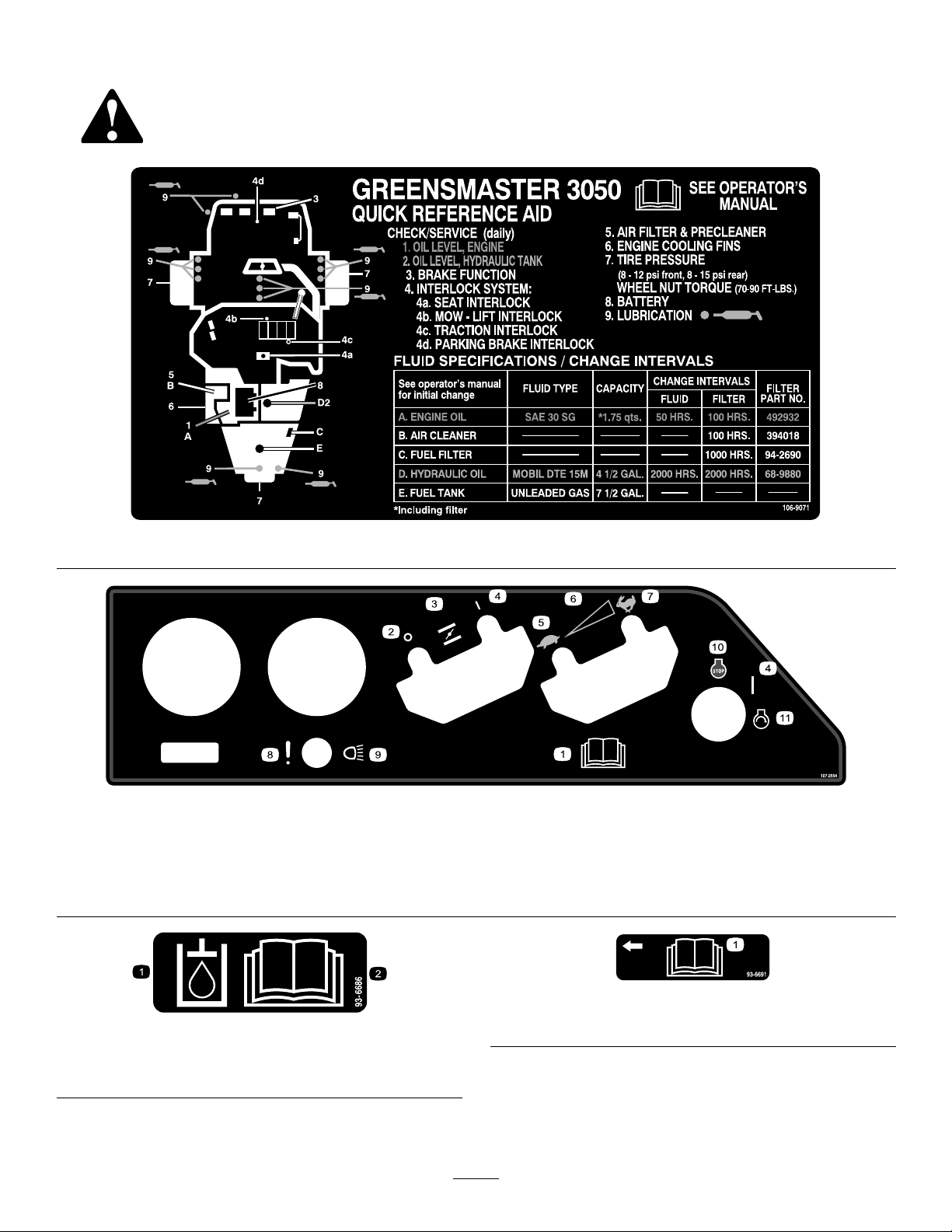
SafetyandInstructionalDecals
Safetydecalsandinstructionsareeasilyvisibletotheoperatorandarelocatednearanyareaof
potentialdanger.Replaceanydecalthatisdamagedorlost.
106–9071
107-2554
1.ReadtheOperator’s
Manual.
2.Off5.Slow8.Failure/malfunction(Leak
3.Choke6.Continuousvariablesetting
4.On
7.Fast10.Engine—stop
detectoralarmtest)
9.Headlights
11.Engine—start
1.Hydraulicoil
2.ReadtheOperator’sManual.
93-6691
93-6686
1.ReadtheOperator’sManual.
7
Page 8
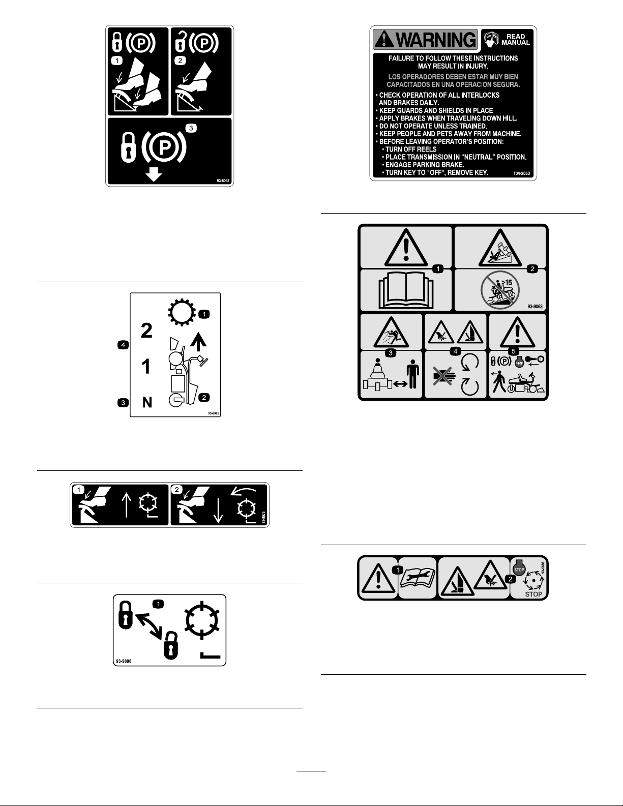
93-8062
1.Tolocktheparkingbrake,
pressthebrakepedaland
theparkingbrakelock.
2.Tounlocktheparking
brake,pressthebrake
pedal.
3.Parkingbrakelock
93-8065
1.Transmission3.Neutral
2.Forwardmotion4.Forwardspeeds
93-8075
1.Presstheliftpedaltoraiseandstopthereels.
2.Pressthemowpedaltolowerandstartthereels.
104–2053
93-8063
CEmodelonly ,replaces104-2053
1.Warning—readtheOperator’sManual.
2.Tippinghazard—donotusethemachineonaslopegreater
than15degrees.
3.Thrownobjecthazard—stayasafedistancefromthe
machine.
4.Cuttinghazardofhandorfoot—stayawayfrommoving
parts.
5.Warning—locktheparkingbrake,stoptheengine,and
removetheignitionkeybeforeleavingthemachine.
1.Lockandunlockthereels
93-6688
1.Warning—readthe
instructionsbefore
servicingorperforming
maintenance.
2.Cuttinghazardofhandor
foot—stoptheengineand
waitformovingpartsto
stop.
93-9898
8
Page 9
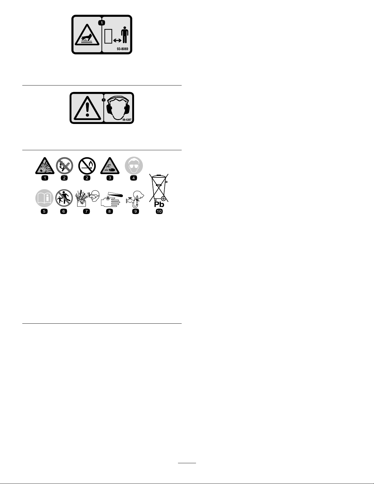
93–8069
1.Hotsurface/burnhazard-stayasafedistancefromthehot
surface.
98-4387
1.Warning—wearhearingprotection.
BatterySymbols
Someorallofthesesymbolsareonyourbattery
1.Explosionhazard
2.Nore,opename,or
smoking.
3.Causticliquid/chemical
burnhazard
4.Weareyeprotection9.Flusheyesimmediately
5.ReadtheOperator’s
Manual.
6.Keepbystandersasafe
distancefromthebattery .
7.Weareyeprotection;
explosivegasescan
causeblindnessandother
injuries
8.Batteryacidcancause
blindnessorsevereburns.
withwaterandgetmedical
helpfast.
10.Containslead;donot
discard.
9
Page 10

Setup
LooseParts
Usethechartbelowtoverifythatallpartshavebeenshipped.
ProcedureDescription
1
2
3
4
5
6
Nopartsrequired
Seat
Nute(5/16inch)
Seatcover
Bolt(1/2x3/4inch)
Washer(1/2inch)
Cover
Socketheadscrew(1/4x3/4inch)
Locknut(1/4inch)
Washer(1/4inch)
Self-tappingscrew
Bolt(1/4x5/8inch)
Nut(1/4inch)
Gaugebar
Bolt(#10x5/8inch)
Jamnut(#10)
Cuttingunit
Washer6
Ballstud6
Grassbasket
Qty.
Use
–
1
4
1
1
1
1
1
1
1
2
2
2
1
1
1
3
3
Activateandchargethebattery.
Mounttheseat.
Securethesteeringarm.
Installthecover.
Installthebattery .
Installthecuttingunits.
7
8
Nopartsrequired
Warningdecal(93-8063)
MediaandAdditionalParts
Description
Operator’sManual
EngineOperator’sManual
OperatorVideo
PartsCatalog
Pre-deliveryInspectionSheet
Noiseratingcerticate
Certicateofcompliance
Emissionswarranty1
Ignitionkeys2
Qty.
1
1
1
1Usetoorderparts.
1
1
1
Readbeforeoperating.
Watchbeforeoperating.
Fileforfuturereference.
Useforstartingtheengine.
–
1
Addrearballast.
InstallCEdecals,ifrequired.
Use
10
Page 11

1
ActivatingandChargingthe
Battery
NoPartsRequired
Procedure
Useonlyelectrolyte(1.265SpecicGravity)toll
batteryinitially.
WARNING
CALIFORNIA
Proposition65Warning
Batteryposts,terminals,andrelated
accessoriescontainleadandleadcompounds,
chemicalsknowntotheStateofCalifornia
tocausecancerandreproductiveharm.
Washhandsafterhandling.
1.Removethewingnuts,washers,andbatteryclamp
andliftoutthebattery.
Important:Donotaddelectrolytewhilethe
batteryisinthemachine.Youcouldspillit,
causingcorrosion.
2.Cleanthetopofthebatteryandremovethevent
Figure3).
caps(
Figure4
1.Electrolyte
4.Allowapproximately20to30minutesforthe
electrolytetosoakintotheplates.Fillasnecessary
tobringtheelectrolytetowithinabout1/4inch(6
mm)ofthebottomofthellwell(
5.Connecta2to4ampbatterychargertothebattery
posts.Chargethebatteryfor2hoursat4ampsor
for4hoursat2ampsuntilthespecicgravityis
1.250orhigherandthetemperatureisatleast60°F
(16°C)withallcellsgassingfreely.
Figure4).
WARNING
Chargingthebatteryproducesgassesthatcan
explode.
Neversmokenearthebatteryandkeepsparks
andamesawayfrombattery.
6.Whenthebatteryischarged,disconnectthecharger
fromtheelectricaloutletandbatteryposts.
Figure3
3.Carefullylleachcellwithelectrolyteuntiltheplates
arecoveredwithabout1/4inch(6mm)ofuid
(Figure4).
Note:Afterthebatteryhasbeenactivated,add
onlydistilledwatertoreplacenormalloss,although
maintenance-freebatteriesshouldnotrequirewater
undernormaloperatingconditions.
WARNING
Batteryterminalsormetaltoolscouldshort
againstmetaltractorcomponentscausing
sparks.Sparkscancausethebatterygassesto
explode,resultinginpersonalinjury.
•Whenremovingorinstallingthebattery,do
notallowthebatteryterminalstotouchany
metalpartsofthetractor.
•Donotallowmetaltoolstoshortbetween
thebatteryterminalsandmetalpartsofthe
tractor.
11
Page 12
WARNING
G011184
1
2
3
G011185
1
2
3
Failuretocorrectlyactivatethebatterymay
resultinbatterygassingand/orpremature
batteryfailure.
2
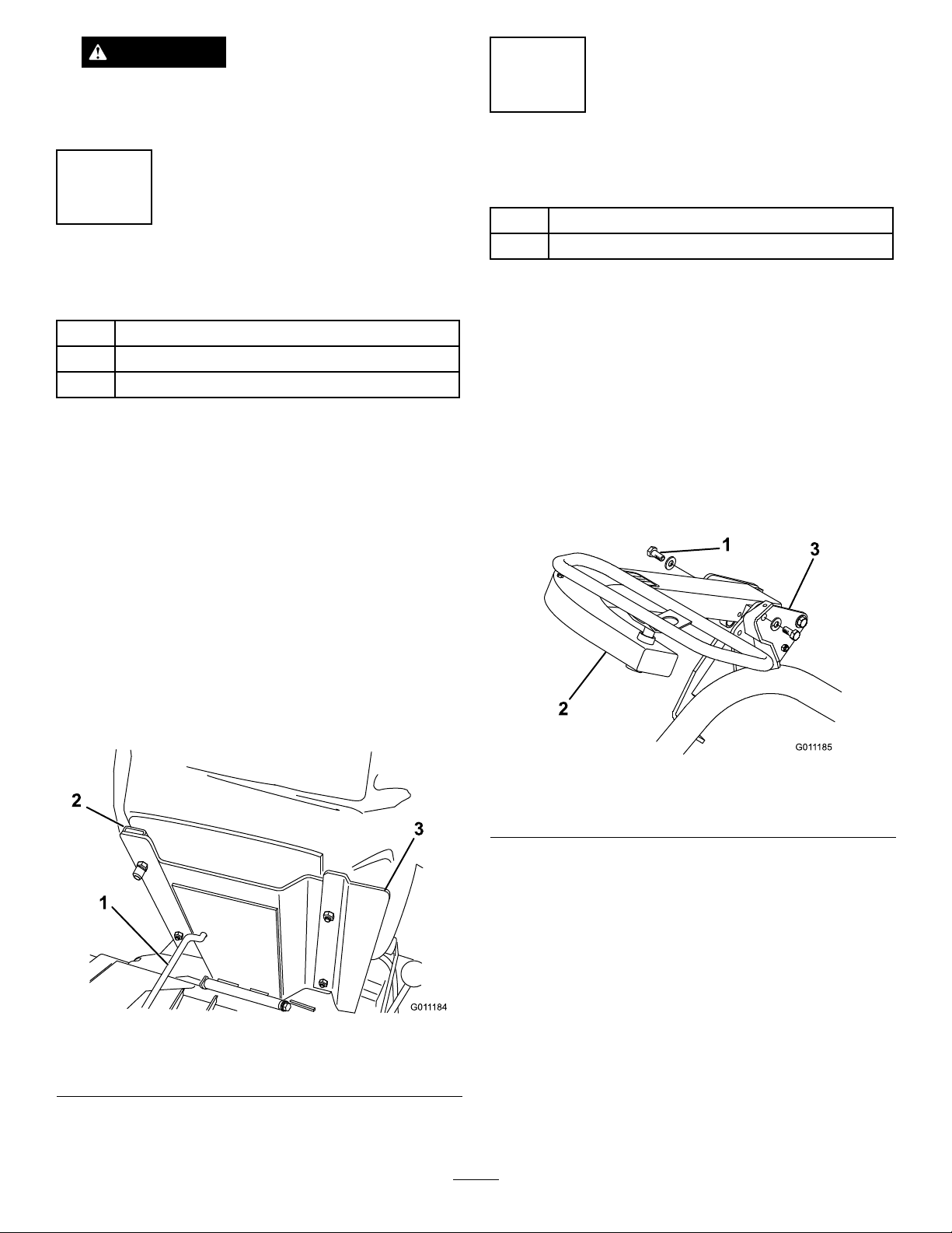
MountingtheSeat
3
SecuringtheSteeringArm
Partsneededforthisprocedure:
1
Bolt(1/2x3/4inch)
1
Washer(1/2inch)
Partsneededforthisprocedure:
1
Seat
4
Nute(5/16inch)
1
Seatcover
Procedure
Note:Mounttheseatslidesinthefrontsetofmounting
holestogainanadditional3inches(7.6cm)inthe
forwardadjustment,orintherearmountingholesforan
additional3inches(7.6cm)intherearwardadjustment.
1.Supporttheseatbaseintheuppositionwiththeseat
supportrod.
2.Removethelocknutssecuringtheseatslidestothe
plywoodshippingbase.Discardthelocknuts.
3.Securetheseat,seatpanel,andseatslidestotheseat
supportwiththelocknuts(5/16inch)(
suppliedinthelooseparts.Mounttheseatpanelon
therightside,positionedasshowninFigure5.
Figure5)
Procedure
1.Removethebolt(1/2x3/4inch)andwasher(1/2
inch)mountedtotheoutsideofthesteeringarm
framebracket.
2.Pivotthesteeringarmupward,aligningthemounting
holesinthearmwiththeholesintheframebracket.
3.Selectthedesiredmountingholeforoperator
comfortandsecurethearmwith2bolts(1/2x3/4
inch)andwashers(1/2inch)(oneeachinloose
parts)(
Figure6).
Figure6
1.Boltandwasher3.Framebracket
2.Steeringarm
1.Seatsupportrod3.Seatpanel
2.Seatslide
Figure5
12
Page 13
4
G011186
1
2
3
5
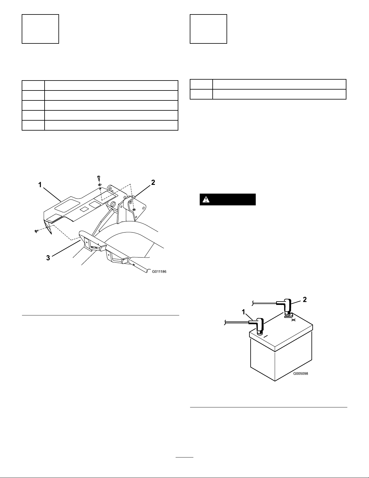
InstallingtheCover
Partsneededforthisprocedure:
1
Cover
1
Socketheadscrew(1/4x3/4inch)
1
Locknut(1/4inch)
1
Washer(1/4inch)
2
Self-tappingscrew
Procedure
1.Alignthecovermountingholeswiththeholesinthe
frametubeandmountingbracket(Figure7).
InstallingtheBattery
Partsneededforthisprocedure:
2
Bolt(1/4x5/8inch)
2
Nut(1/4inch)
Procedure
1.Mountthebatterywiththebatteryterminalstoward
thehydraulictankonthemachine.
2.Connectthepositivebatterycable(red)fromthe
startersolenoidtothepositivepost(+)ofthebattery
(Figure8).Secureitwithawrenchandcoatthe
terminalwithpetroleumjelly .Makesurethecable
willcleartheseat,intherear-mostposition,which
couldcausewearordamagetothecable.
WARNING
Batteryterminalsormetaltoolscouldshort
againstmetaltractorcomponentscausing
sparks.Sparkscancausethebatterygassesto
explode,resultinginpersonalinjury.
•Whenremovingorinstallingthebattery,do
notallowthebatteryterminalstotouchany
metalpartsofthetractor.
Figure7
Shownwithsteeringarmremoved
1.Cover
2.Mountingbracket
2.Looselysecuretherearofthecovertothetopof
themountingbracketwithasocketheadscrew(1/4
x3/4inch),washer(1/4inch),andalocknut(1/4
inch)(Figure7).
3.Looselysecurethefrontofthecovertotheframe
tubewithtwoselftappingscrews(Figure7).Tighten
allofthecovermountingfasteners.
3.Frametube
•Donotallowmetaltoolstoshortbetween
thebatteryterminalsandmetalpartsofthe
tractor.
Figure8
1.Negative(-)2.Positive(+)
3.Connecttheblackgroundcable(fromtheengine
base)tothenegative(-)postofthebattery.Secureit
withawrenchandcoattheterminalwithpetroleum
jelly.
13
Page 14
WARNING
Incorrectbatterycableroutingcoulddamage
thetractorandcablescausingsparks.Sparks
cancausethebatterygassestoexplode,
resultinginpersonalinjury.
•Alwaysdisconnectthenegative(black)
batterycablebeforedisconnectingthe
positive(red)cable.
•Alwaysconnectthepositive(red)battery
cablebeforeconnectingthenegative(black)
cable.
4.Installthebatteryclampandwashersandsecure
themwiththewingnuts.
5.Placetheterminalcoveroverthepositive(+)battery
post.
6
InstallingtheCuttingUnits
(ForCuttingUnitModels04610
and04611Only)
Partsneededforthisprocedure:
1
Gaugebar
1
Bolt(#10x5/8inch)
1
Jamnut(#10)
3
Cuttingunit
6Washer
6Ballstud
3
Grassbasket
Figure9
1.Pullframe
2.Pullarm
3.Slidethecuttingunitunderthepullframewhile
hookingthelifthookontotheliftarm(Figure10).
1.Liftarm2.Lifthook
4.Slidethesleevebackontheballjointandrotatethe
pullarmdownsothesockettsovertheballstud.
Releasethesleevesoitslidesoverthestudandlocks
theassembliestogether(
5.Mountthebasketsonthepullframes,loosenthe
jamnutsonthepullarms,andadjusttheballsockets
untilthereis1/4to1/2inch(6to13mm)clearance
betweenthelipofthebasketandthereelbladesor
thefrontshield.
3.Ballstud
Figure10
Figure9).
Procedure
Note:Whensharpening,settingtheheight-of-cut
orperformingothermaintenanceproceduresonthe
cuttingunits,storethecuttingunitreelmotorsinthe
supporttubesonthefrontoftheframetoprevent
damagetothehoses.
1.Removethecuttingunitsfromthecartons.Assemble
andadjustthemaslistedinthecuttingunitOperator’s
Manual.Usethegaugebarfromtheloosepartskit
toadjusttheheightofcut.
2.Mountawasherandballstudtoeachendofthe
frontrolleronthecuttingunits(
Figure9).
Note:Thispreventsthebasketfromtippingthe
cuttingunitforward,causingtheliftrollertocome
offoftheliftarmwhileinthemowingoperation.
Besurethebasketlipisequidistantfromthereel
bladesallacrosseachreel.Ifthebasketistooclose
tothereel,itispossibleforthereeltocontactthe
basketwhenthecuttingunitisraisedoffofthe
ground.
6.Alignthesocketsintheballjointssotheopenside
ofthesocketiscenteredtowardstheballstud.
Tightenthejamnutstosecurethesocketsinposition
(Figure11).
14
Page 15
Figure11
1.Pullarm3.Balljoint
2.Jamnut
7.Assemblethemountingboltsforthereeldrive
motortoeachcuttingunit.Leaveapproximately1/2
inch(13mm)ofthreadsexposedoneachmounting
bolt(Figure12).
7
AddingRearBallast
NoPartsRequired
Procedure
ThisunitcomplieswiththeANSIB71.4-2004Standard
when40lbofcalciumchlorideballastisaddedtothe
rearwheel.
Important:Ifapunctureoccursinatirewith
calciumchloride,removetheunitfromtheturfarea
asquicklyaspossible.Topreventpossibledamage
totheturf,immediatelysoaktheaffectedareawith
water.
8
Figure12
1.Bolts2.Drivemotor
8.Removetheprotectivecoversfromthecuttingunits
andthereeldrivemotorshafts.
Note:Retaintheprotectivecoversforthecutting
units.Installthemwheneverthereeldrivemotors
areremovedtoprotectthecuttingunitbearings
fromcontamination.
9.Usingahandpumpgreasegun,llthecavityatthe
endofthecuttingunitwith#2generalpurpose
grease.
10.Coatthesplineshaftofthemotorwithcleangrease
andinstallthemotorbyrotatingthemotorclockwise
sothatthemotorangesclearthestuds.Rotate
themotorcounterclockwiseuntiltheangesare
encirclingthestuds.
InstallCEDecals
Partsneededforthisprocedure:
1
Warningdecal(93-8063)
Procedure
IfthismachinewillbeusedintheCE,afxthewarning
decal(93-8063)overEnglishwarningdecal(104-2053).
11.Tightenthemountingbolts(
Figure12).
15
Page 16

ProductOverview
1
2
3
4
5
G011189
1
2
3
4
5
6
7
Controls
Figure13
1.Mowpedal4.Brakepedal
2.Liftpedal
3.Tractionpedal
5.Parkingbrakebutton
TractionandStoppingPedal
Thetractionpedal(Figure13)hasthreefunctions:to
makethemachinemoveforward,tomoveitbackward,
andtostopthemachine.Pressthetopofthepedalto
moveforwardandthebottomofthepedaltomove
backwardortoassistinstoppingwhenmovingforward.
Also,allowthepedaltomovetotheneutralpositionto
stopthemachine.Foroperatorcomfort,donotrestthe
heelofyourfootonreversewhenoperatingforward
Figure14).
(
Figure14
MowPedal
Pressingthemowpedal(Figure13)fullyduring
operationlowersthecuttingunitsandstartsthereels.
Themowpedalwillstaypressedduetodetentactionof
thevalvebankduringoperation.Theoperatordoesnot
needtoholdthepedaldown.
ThrottleControl
Thethrottlecontrol(Figure15)givestheoperatorthe
abilitytocontrolthespeedoftheengine.Movingthe
throttlecontroltowardtheFastpositionincreasesthe
engineRPM;movingthethrottlecontroltowardSlow
willdecreasetheengineRPM.
Note:Theenginecannotbestoppedbytheuseofthe
BrakePedal
throttlecontrol.
Thebrakepedal(Figure13)actuatesanautomotive
drum-typemechanicalbrakelocatedateachtraction
wheel.
LiftPedal
Pressingtheliftpedal(Figure13)duringoperationstops
thereelsfromturningandliftsthecuttingunits.Thelift
pedalmustbefullypresseduntilthecuttingunitsare
fullyraisedandhavestoppedrotating.
ParkingBrakeButton
Pressingthebrakepedaltoactuatethebrakeassembly,
thenpressingthesmallbuttonindicated(Figure13)will
keepthebrakesactuatedforparking.Disengageitby
pressingthebrakepedal.Locktheparkingbrakebefore
youleavethemachine.
Figure15
1.Chokecontrol
2.Throttlecontrol
3.Ignitionswitch
4.Voltmeter
5.Hourmeter
6.Fuse(10amp)
7.Seatadjustinglever
16
Page 17

Choke
G011190
1
G011191
1
G011192
1
ShiftSelector
Tostartacoldengine,closethecarburetorchokeby
movingthechokecontrol(Figure15)forwardtothe
Closedposition.Aftertheenginestarts,regulatethe
choketokeeptheenginerunningsmoothly.Assoon
aspossible,openthechokebypullingitrearwardto
theOpenposition.Awarmenginerequireslittleorno
choking.
HourMeter
Thehourmeter(Figure15)indicatesthetotalhoursthe
machinehasoperated.Itstartstofunctionwheneverthe
keyswitchisrotatedtoOn.
SeatAdjustingLever
Thislever,ontheleftsideoftheseat(Figure15),allows
a4inchforeandaftadjustmentoftheseat.
IgnitionSwitch
Insertthekeyintotheswitch(Figure15)andturnit
clockwiseasfaraspossibletotheStartpositiontostart
theengine.Releasethekeyassoonastheenginestarts;
thekeywillmovetotheOnposition.Turnthekey
counterclockwisetotheOffpositiontostoptheengine.
Theshiftselectorislocatedonthetopoftherighthand
panel(
Figure17).Itprovidestwotractionselections
plusaNeutralposition.Itispermissibletoshiftfrom
oneselectiontoanotherwhilethemachineisinmotion.
Nodamagewillresult.
•Neutral—usedforstartingtheengine
•No.1Position—usedforgreensmowingoperation
•No.2Position—usedfortransportoperation
Important:Ifthemachineisoperatedinreverse
withthecuttingunitsdown,thecuttingunitswill
bepulledoffoftheliftarms.
Figure17
1.Shiftselector
FuelShut-OffValve
Voltmeter
Thevoltmeter(Figure15)indicatestheelectricalsystem
voltage.
Fuse
Thefuse(Figure15)ispartoftheelectricalcircuit.It
containsa10ampfuse(15ampmaximum).
MowLockoutLever
Thelockoutleverlocksthemowpedalpreventing
accidentalstartingofthecuttingunits.Tounlockit,
pullthemowlockoutpinoutward(
clockwise,andinserttheendintotherearholeinthe
bracket.
Figure16
1.Mowlockoutlever
Figure16),rotateit
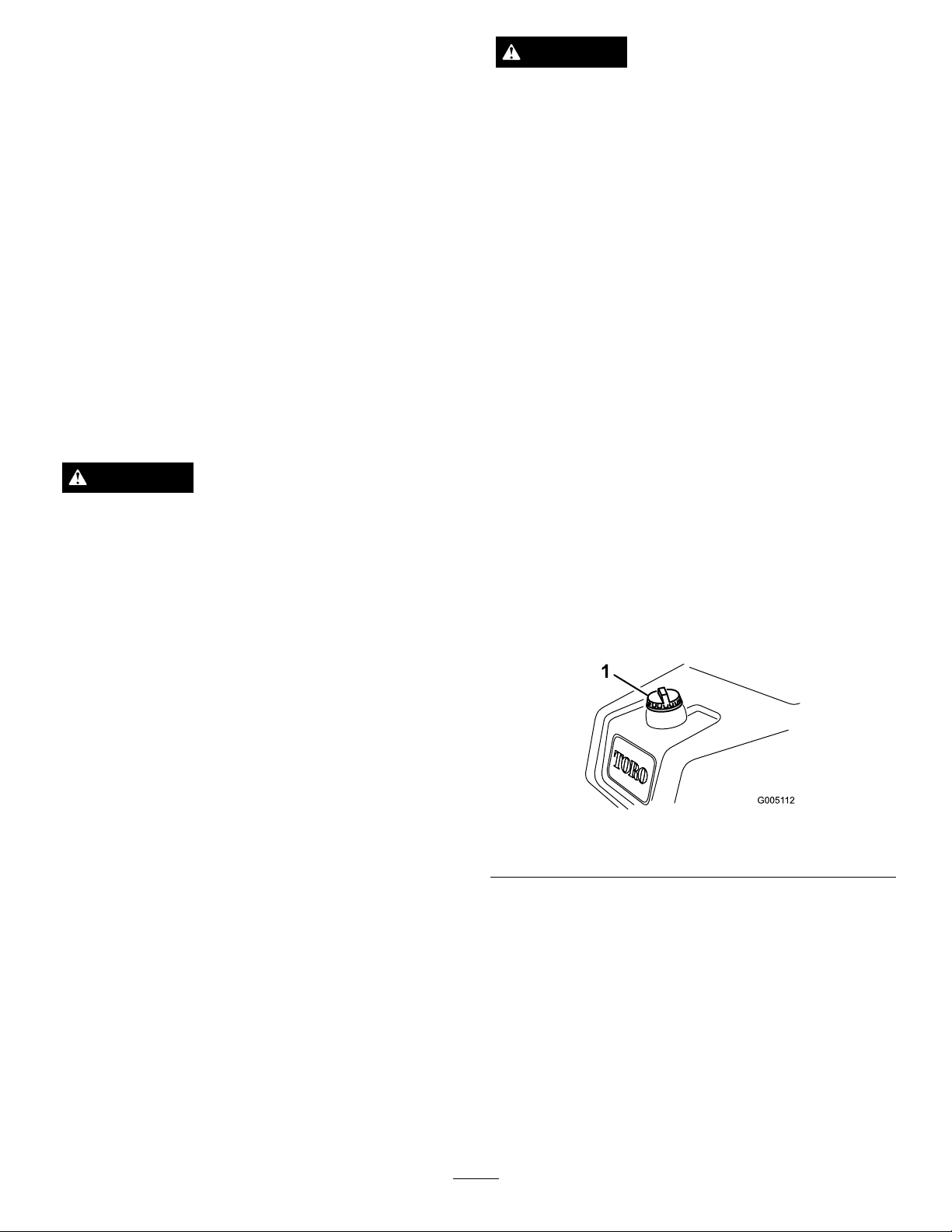
Closethefuelshut-offvalve(Figure18),underthefuel
tank,whenstoringortransportingthemachineona
truckortrailer.
Figure18
1.Fuelshut-off(underthefueltank)
Specications
Note:Specicationsanddesignaresubjecttochange
withoutnotice.
OverallWidthw/reels69–3/4inches(177cm)
OverallLength90inches(228.6cm)
OverallHeight48-1/2inches(123.2cm)
OverallWeightwithReels1256lb(570kg)
NetWeight(wet)930lb(422kg)
17
Page 18

WidthofCut59inches(149.9cm)
Operation
WheelTread
WheelBase
1stGearSpeed
2ndGearSpeed
ReverseSpeed1.9MPH(3.1km/h)
ReelSpeed
49-1/2inches(125.7cm)
46-7/8inches(119.1cm)
3.8MPHapproximately
(6.1km/h)
8.1MPHapproximately
(13km/h)
1975RPMapproximately
Attachments/Accessories
AselectionofToroapprovedattachmentsand
accessoriesareavailableforusewiththemachineto
enhanceandexpanditscapabilities.Contactyour
AuthorizedServiceDealerorDistributororgoto
www.Toro.comforalistofallapprovedattachments
andaccessories.
Note:Determinetheleftandrightsidesofthe
machinefromthenormaloperatingposition.
ThinkSafetyFirst
Pleasecarefullyreadallofthesafetyinstructions
andsymbolsinthesafetysection.Knowingthis
informationcouldhelpyouorbystandersavoidinjury.
Theuseofprotectiveequipment,suchasbutnot
limitedto,foreyes,ears,feet,andheadisrecommended.
CAUTION
Thismachineproducessoundlevelsinexcessof
85dBAattheoperator’searandcancausehearing
lossthroughextendedperiodsofexposure.
Wearhearingprotectionwhenoperatingthis
machine.
CheckingtheEngineOil
Theengineisshippedwith1-3/4quarts(1.65liters)
(w/lter)ofoilinthecrankcase;however,theoillevel
mustbecheckedbeforeandaftertheengineisrst
started.
Theengineusesanyhigh-qualitydetergentoilhaving
theAmericanPetroleumInstitute(API)service
classicationofSG,SH,orSJorhigher.The
recommendedviscosity(weight)isSAE30.
1.Positionthemachineonalevelsurface.
2.Unscrewthedipstickandwipeitwithacleanrag.
Screwthedipstickintothetubeandmakesureitis
seatedfully(
1.Dipstick2.Fillercap
Figure19).
Figure19
3.Unscrewthedipstickoutofthetubeandcheckthe
oillevel.
18
Page 19
4.Iftheoillevelislow,removethellercapfromthe
valvecoverandpouroilintotheopeninginthe
valvecoveruntiltheoillevelisuptotheFullmark
onthedipstick.Addtheoilslowlyandcheckthe
leveloftenduringthisprocess.Donotoverll.
Important:Checktheoillevelevery8
operatinghoursordaily .
5.Installthellercapanddipstickrmlyinplace.
FillingtheFuelTank
Useunleadedregulargasolinesuitableforautomotive
use(85pumpoctaneminimum).Leadedregular
gasolinemaybeusedifunleadedregularisnotavailable.
Important:Neverusemethanol,gasoline
containingmethanol,orgasoholcontainingmore
than10%ethanolbecausethefuelsystemcouldbe
damaged.Donotmixoilwithgasoline.
DANGER
Incertainconditions,gasolineisextremely
ammableandhighlyexplosive.Areorexplosion
fromgasolinecanburnyouandothersandcan
damageproperty.
•Fillthefueltankoutdoors,inanopenarea,
whentheengineiscold.Wipeupanygasoline
thatspills.
DANGER
Incertainconditionsduringfueling,static
electricitycanbereleasedcausingasparkwhich
canignitethegasolinevapors.Areorexplosion
fromgasolinecanburnyouandothersandcan
damageproperty.
•Alwaysplacegasolinecontainersontheground
awayfromyourvehiclebeforelling.
•Donotllgasolinecontainersinsideavehicle
oronatruckortrailerbedbecauseinterior
carpetsorplastictruckbedlinersmayinsulate
thecontainerandslowthelossofanystatic
charge.
•Whenpractical,removegas-powered
equipmentfromthetruckortrailerandrefuel
theequipmentwithitswheelsontheground.
•Ifthisisnotpossible,thenrefuelsuch
equipmentonatruckortrailerfromaportable
container,ratherthanfromagasolinedispenser
nozzle.
•Ifagasolinedispensernozzlemustbeused,
keepthenozzleincontactwiththerimofthe
fueltankorcontaineropeningatalltimesuntil
fuelingiscomplete.
1.Cleanaroundthefueltankcapandremoveit
(Figure20).
•Neverllthefueltankinsideanenclosedtrailer.
•Donotllthefueltankcompletelyfull.Add
gasolinetothefueltankuntilthelevelis1inch
(25mm)belowthebottomofthellerneck.
Thisemptyspaceinthetankallowsgasoline
toexpand.
•Neversmokewhenhandlinggasoline,andstay
awayfromanopenameorwheregasoline
fumesmaybeignitedbyaspark.
•Storegasolineinanapprovedcontainerand
keepitoutofthereachofchildren.Neverbuy
morethana30-daysupplyofgasoline.
•Donotoperatewithoutentireexhaustsystem
inplaceandinproperworkingcondition.
Figure20
1.Fueltankcap
2.Addunleadedregulargasolinetothefueltankuntil
thelevelis1inch(25mm)belowthebottomofthe
llerneck.
Thisspaceinthetankallowsgasolinetoexpand.
Donotllthefueltankcompletelyfull.
Note:Fueltankcapacityis7U .S.gallons(26.6
liters)
3.Installthefueltankcapsecurely .Wipeupany
gasolinethatmayhavespilled.
19
Page 20

CheckingtheHydraulicFluid
Level
Thehydraulicuidreservoirislledatthefactorywith
approximately4.5U.S.gallons(17l)ofhighquality
hydraulicuid.Checkthelevelofthehydraulicuid
beforetheengineisrststartedanddailythereafter.
Therecommendedreplacementuidisasfollows:
ToroPremiumAllSeasonHydraulicFluid(Availablein5
gallonpailsor55gallondrums.SeepartscatalogorT oro
distributorforpartnumbers.)
Alternateuids:IftheT orouidisnotavailable,other
uidsmaybeusedprovidedtheymeetallthefollowing
materialpropertiesandindustryspecications.Wedo
notrecommendtheuseofsyntheticuid.Consult
withyourlubricantdistributortoidentifyasatisfactory
product
Note:Torowillnotassumeresponsibilityfordamage
causedbyimpropersubstitutions,souseonlyproducts
fromreputablemanufacturerswhowillstandbehind
theirrecommendation.
HighViscosityIndex/LowPourPointAnti-wearHydraulic
Fluid,ISOVG46
MaterialProperties:
Viscosity,ASTMD445cSt@40°C44to48
ViscosityIndexASTM
D2270
PourPoint,ASTMD97-34°Fto-49°F
IndustrySpecications:
VickersI-286-S(QualityLevel),VickersM-2950-S
(QualityLevel),DenisonHF-0
cSt@100°C7.9to8.5
140to160
Note:Manyhydraulicuidsarealmostcolorless,
makingitdifculttospotleaks.Areddyeadditive
forthehydraulicsystemoilisavailablein2/3oz.(20
ml)bottles.Onebottleissufcientfor4-6gal(15-22
1)ofhydraulicoil.Orderpartno.44-2500fromyour
authorizedTorodistributor.Thisreddyeisnot
recommendedforusewithbiodegradableuids.
Usefoodcoloring.
1.Positionthemachineonalevelsurface.Makesure
themachinehascooleddownsotheoiliscold.
2.Removethecapfromthetopofthereservoir
andchecktheuidlevel.Theuidshouldbe
approximately3-1/2in.(89mm)belowthetopof
thellhole(
Figure21).
Important:Topreventsystemcontamination,
cleanthetopofthehydraulicoilcontainers
beforepuncturingthem.Ensurethatthepour
spoutandfunnelareclean.
Note:Makeaclosevisualinspectionofthe
hydrauliccomponents.Inspectthemforleaks,loose
fasteners,missingparts,improperlyroutedlines,etc.
Makeanycorrectionsnecessary.
Important:TheISOVG46Multigradeuidhas
beenfoundtoofferoptimalperformanceinawide
rangeoftemperatureconditions.Foroperationin
consistentlyhighambienttemperatures,65°F(18°
C)to120°F(49°C),ISOVG68hydraulicuidmay
offerimprovedperformance.
PremiumBiodegradableHydraulicFluid-Mobil
EALEnviroSyn46H
Important:MobilEALEnviroSyn46Histheonly
syntheticbiodegradableuidapprovedbyT oro.
Thisuidiscompatiblewiththeelastomersused
inT orohydraulicsystemsandissuitablefora
wide-rangeoftemperatureconditions.Thisuidis
compatiblewithconventionalmineraloils,butfor
maximumbiodegradabilityandperformancethe
hydraulicsystemshouldbethoroughlyushedof
conventionaluid.Theoilisavailablein5gallon
(19l)containersor55gallondrumsfromyour
MobilDistributor.
Figure21
1.Hydraulicreservoir
2.Screen
3.Fluidlevel3-1/2in.from
topofllhole
3.Iftheoillevelislow ,slowlyllthereservoirwith
ISOVG46orequivalenthydraulicoiluntilthelevel
isuptothecorrectlevel.Donotmixoils.
4.Installthecap.
CheckingtheTirePressure
Thetiresareover-inatedatthefactoryforshipping
purposes.Reducethepressuretotheproperlevels
beforestartingtheunit.
Varythetirepressureforthefrontwheels,depending
uponyourturfconditions,fromaminimumof8psito
amaximumof12psi(55to83kPa).
20
Page 21

Varythetirepressurefortherearwheelfroma
minimumof8psitoamaximumof15psi(55to103
kPa).
CheckingtheTorqueofthe
WheelNuts
WARNING
Failuretomaintainpropertorqueofthewheelnuts
couldresultinpersonalinjury.
4.MovethechokelevertotheOnposition(only
whenstartingacoldengine)andthethrottlelever
tothehalfthrottleposition.
5.Insertandrotatetheignitionkeyclockwiseuntil
theenginestarts.Aftertheenginestarts,regulate
thechoketokeeptheenginerunningsmoothly.
Assoonaspossible,openthechokebypulling
itrearwardtotheOffposition.Awarmengine
requireslittleornochoking.
6.Checkthemachineoutwiththefollowing
proceduresaftertheenginehasstarted:
Torquethewheelnutsto70-90ft-lbafter1-4hours
ofoperationandagainafter10hoursofoperation.
Torqueevery200hoursthereafter.
Break-inPeriod
RefertotheEngineManualsuppliedwiththe
machineforoilchangeandmaintenanceprocedures
recommendedduringthebreak-inperiod.
Only8hoursofmowingoperationisrequiredforthe
break-inperiod.
Sincethersthoursofoperationarecriticaltofuture
dependabilityofthemachine,monitoritsfunctions
andperformancecloselysothatminordifculties,
whichcouldleadtomajorproblems,arenotedandcan
becorrected.Inspectthemachinefrequentlyduring
break-inforsignsofoilleakage,loosefasteners,orany
othermalfunction.
Toensureoptimumperformanceofthebrakesystem,
burnish(break-in)thebrakesbeforeusingthemachine.
Toburnishthebrakes,rmlyapplythebrakesand
drivethemachineatmowingspeeduntilthebrakes
arehot,asindicatedbytheirsmell.Anadjustment
tothebrakesmayberequiredafterbreak-in;referto
AdjustingtheBrakes(page32).
StartingtheEngine
Note:Inspecttheareabeneaththemowerstobe
certaintheyareclearofdebris.
1.Unlockthemowlockoutleverbypullingthepin
outward,rotatingitclockwise,andinsertingtheend
intotherearholeinthebracket.
2.Sitontheseat,placetheshiftselectorinNeutral,
andcheckthemowandliftpedalstobesurethey
arelevelwithoneanother.
A.MovethethrottlecontroltotheFastposition
andmomentarilyengagethereelsbypressing
themowpedal.Thecuttingunitsshoulddrop
andallthereelsshouldturn.
B.Operatetheliftpedal.Thecuttingreelsshould
stopandthecuttingunitsshouldraisetothefull
transportposition.
Important:Stoptheengine.Checkthelip
ofeachbaskettobesureitisnotincontact
withthereelduringoperation.Adjust
thepullarmsifcontactisnoted;referto
InstallingtheCuttingUnits.
C.Pressthebrakepedaltokeepthemachinefrom
moving,andoperatethetractionpedalthrough
theforwardandreversepositions.
D.Continuetheaboveprocedurefor1–2minutes.
Neutralizethetractionleverandmowandlift
pedals,locktheparkingbrake,andturnthe
engineoff.
E.Checkforoilleaks.Ifoilleaksappear,check
thetightnessofthehydraulicttings.Ifoil
leakscontinuetoappear,contactyourlocal
ToroDistributorforassistanceand,ifnecessary,
replacementparts.
Important:Themotororwheelsealsmay
showsometraceofoilforashortperiodof
timeuntilthemachinebreak-inperiodhas
transpired.
Note:Sincethemachineisnewandthe
bearingsandreelsaretight,itisnecessarytouse
theFastthrottlecontrolpositionforthischeck.
Afastthrottlesettingmaynotberequiredafter
thebreak-inperiod.
3.Removeyourfootfromthetractionpedalandmake
surethepedalisintheNeutralposition.
21
Page 22

CheckingtheSafetyInterlock
System
CAUTION
Ifthesafetyinterlockswitchesaredisconnectedor
damagedthemachinecouldoperateunexpectedly
causingpersonalinjury.
•Donottamperwiththeinterlockswitches.
•Checktheoperationoftheinterlockswitches
dailyandreplaceanydamagedswitchesbefore
operatingthemachine.
Thepurposeoftheinterlocksystem(Figure22)isto
preventtheenginefromcrankingorstartingunlessthe
tractionshiftselectorisinNeutralandthecuttingunits
aredisengaged.Inaddition,theenginewillstopwhen:
•Thecuttingunitsareengagedwiththeoperatoroff
oftheseat.
•ThetractionshiftselectorisintheNo.1orNo.2
positionwiththeoperatoroffoftheseat.
switchonthevalvebankisoperatingcorrectly.If
theenginedidnotcrank,proceedtostep3.Ifthe
enginecranked,contactyourlocalToroDistributor
forassistance
3.Sitontheseatandengagetheparkingbrake.Fully
presstheliftpedalandreleaseit.Movethetraction
shiftselectortoneutralandtrytostarttheengine.
Theengineshouldstartandcontinuetorun,which
meansthetractionswitchandmow/liftswitchon
thevalvebankareoperatingcorrectly;proceedto
4..Iftheenginecrankedbutdidnotstart,the
step
problemisnotintheinterlocksystem.Ifengine
didnotcrank,contactyourlocalToroDistributor
forassistance.
4.Sitontheseat,engagetheparkingbrake,andmove
thetractionshiftselectortoneutral.Pressthemow
pedalandtrytostarttheengine.Theengineshould
notcrank,whichmeansthemow/liftswitchis
operatingcorrectly.Iftheenginedidnotcrank,
proceedtostep
yourlocalT oroDistributorforassistance.
5.Sitontheseatandmovethetractionshiftselector
toneutral.Fullypresstheliftpedalandrelease
it.Starttheengineanddepressthemowpedal.
Carefullyrisefromtheseat;theengineshouldstop.
Iftheenginestops,theinterlocksystemisoperating
correctly.Iftheenginedoesnotstop,stopthe
engineandndtheproblembeforeoperatingthe
machineagain.Ifassistanceisrequired,contact
yourlocalToroDistributor
5.Iftheenginecranked,contact
Figure22
1.Tractionswitch
2.Seatswitch
Performthefollowingsystemchecksdailytobesure
theinterlocksystemisoperatingcorrectly:
1.Sitontheseat,engagetheparkingbrake,andmove
theshiftselectortoneutral.Removeyourfoot
fromthetractionpedalandmakesurethepedalis
inneutral.Fullydepresstheliftpedalandrelease
it.Trytostarttheengine.Theengineshould
crankandrun,whichmeanstheinterlocksystemis
operatingcorrectly.Iftheenginedidcrank,proceed
tostep
localToroDistributorforassistance.
2.Sitontheseatandengagetheparkingbrake.Press
theliftpedalfullyandreleaseit.Movethetraction
shiftselectortothe#1and#2positionswhile
tryingtostarttheengineineachposition.The
engineshouldnotcrank,whichmeansthetraction
2.Iftheenginedidnotcrank,contactyour
3.Mow/liftswitch
6.Sitontheseatandmovethetractionshiftselector
toNeutral.Fullypresstheliftpedalandreleaseit.
Starttheengineanddrivetoanopenareathatis
freeofdebrisandforeignobjects.Keepallpeople,
especiallychildren,awayfromthefrontofthe
machineandoutoftheareaofoperation.Movethe
shiftselectortoNeutral,makesurethemowpedal
isdisengaged,setthethrottlecontrolathalfspeed,
anddepressthebrakepedal(donotengagethe
parkingbrakebutton).Whileholdingthesteering
wheel,braceyourfeetonthefootdeckandbrake
pedalandmovetheshiftselectortothe#1position.
Carefullyrisefromtheseat;theengineshouldstop.
Iftheenginestops,theinterlocksystemisoperating
correctly.
7.Repeatstep6withtheshiftselectorinthe#2
position.Iftheenginedoesnotstop,stopthe
engineandndtheproblembeforeoperatingthe
machineagain.Ifassistanceisrequired,contact
yourlocalToroDistributor.
Note:Themachineisequippedwithaninterlock
switchontheparkingbrake.Theenginewillstopifthe
22
Page 23

tractionshiftselectorisinthe#1and#2positionswith
theparkingbrakeengaged.
PreparingtheMachinefor
Mowing
Toassistinaligningthemachineforsuccessivecutting
passes,itissuggestedthefollowingbedonetotheNo.
2andNo.3cuttingunitbaskets:
BeforeMowing
Inspectthegreenfordebris,removetheagfromthe
cup,anddeterminethebestdirectiontomow .Basethe
directiontomowonthepreviousmowingdirection.
Alwaysmowinanalternatepatternfromtheprevious
mowingsothatthegrassbladeswillbelessapttolay
downandthereforebedifculttotrapbetweenthereel
bladesandbedknife.
1.Measureinapproximately5inches(12.7cm)from
theouteredgeofeachbasket.
2.Eitherplaceastripofwhitetapeorpaintaline
ontoeachbasketparallelingtheouteredgeofeach
basket(
1.Alignmentstrip
2.Approximately5inches
(12.7cm)
Figure23).
Figure23
3.Cutgrassonright
4.Keepfocalspot6-10ft
(1.8-3m)aheadofthe
machine.
TrainingPeriod
Beforemowinggreenswiththemachine,itis
recommendedthatyoundaclearareaandpractice
startingandstopping,raisingandloweringthecutting
units,turning,etc.Thistrainingperiodwillbe
benecialtotheoperatoringainingcondenceinthe
performanceofthemachine.
Important:IfyoushifttotheNo.2position
whilecuttinggreens,noincreaseinspeedwill
result.However,asuddenincreaseinspeedwill
developwhenyouactuatetheliftpedal.Forsafety
purposes,itisrecommendedthatyouuseonlythe
No.1positionforcuttinggreensandtheNo.2
positionfortransport.
Mowing
1.Approachthegreenwiththeshiftselectorinthe
No.1position.Startononeedgeofthegreenso
thattheribbonprocedureofcuttingmaybeused.
Thisholdscompactiontoaminimumandleavesa
neat,attractivepatternonthegreens.
Important:ShifttotheNo.1positionwhen
approachingagreenbecausethemachine
speedwillautomaticallybereducedwhenthe
cuttingunitsareengaged.Higherspeedwill
resumewhenthecuttingunitsaredisengaged.
2.Actuatethemowpedalasthefrontedgeofthe
grassbasketscrosstheouteredgeofthegreen.
Thisproceduredropsthecuttingunitstotheturf
andstartsthereels.
Note:TheNo.1(rear)cuttingunitreelwillnot
startuntilallthecuttingunitsareonthegroundand
theNo.2andNo.3cuttingunitsarecutting.
Important:Familiarizeyourselfwiththefact
thattheNo.1cuttingunitreelisdelayedand
therefore,youshouldpracticetotrytogain
therequiredtimingnecessarytominimizethe
cleanupmowingoperation.
3.Overlapaminimalamountwiththepreviouscut
onreturnpasses.Toassistinmaintainingastraight
lineacrossthegreenandkeepthemachinean
equaldistancefromtheedgeofthepreviouscut,
establishanimaginarysightlineapproximately6to
10ft(1.8to3m)aheadofthemachinetotheedge
oftheuncutportionofthegreen(
Figure24).Somenditusefultoincludetheouter
edgeofthesteeringwheelaspartofthesightline;
i.e.keepthesteeringwheeledgealignedwithapoint
thatisalwayskeptthesamedistanceawayfromthe
frontofthemachine(
Figure23andFigure24).
Figure23and
23
Page 24

Figure24
1.Alignmentstrip
2.Approximately5inches
(12.7cm)
3.Cutgrassonleft
4.Keepfocalspot6-10ft
(1.8-3m)aheadofthe
machine.
4.Asthefrontofthebasketscrosstheedgeofthe
green,presstheliftpedal.Thiswillstopthereels
andliftthecuttingunits.Timingofthisprocedureis
important,sothemowersdonotcutintothefringe
area.However,asmuchofthegreenaspossible
shouldbecuttominimizetheamountofgrassleft
tomowaroundtheouterperiphery.
5.Cutdownonoperatingtimeandeaselineupforthe
nextpassbymomentarilyturningthemachinein
theoppositedirection,thenturninginthedirection
oftheuncutportion;i.e.,ifintendingtoturnright,
rstswingslightlyleft,thenright.Thiswillassistin
gettingthemachinemorequicklyalignedforthe
nextpass.Followthesameprocedureforturningin
theoppositedirection.Itisagoodpracticetotryto
makeasshortofaturnaspossible.However,turn
inawiderarcduringwarmerweathertominimize
thepossibilityofbruisingtheturf.
thedirectionofmowingfromthepreviouscutting.
Replacetheag.
7.Raisethecuttingunitsandemptythegrassbaskets
ofallclippingsbeforetransportingtothenext
green.Heavywetclippingsplaceanunduestrainon
thebasketsandwilladdunnecessaryweighttothe
machine,therebyincreasingtheloadontheengine,
hydraulicsystem,brakes,etc.
TransportOperation
Makesurethecuttingunitsareinthefullupposition.
SettheshiftselectorinNo.2ifconditionswillpermit
fastergroundspeed.ShifttoNo.1andoperateat
slowergroundspeedsinroughorhillyareas.Usethe
brakestoslowthemachinewhilegoingdownsteep
hillstoavoidlossofcontrol.Alwaysapproachrough
areasatareducedspeed(shiftselectorinNo.1),and
crosssevereundulationscarefully.Familiarizeyourself
withthewidthofthemachine.Donotattempttopass
betweenobjectsthatareclosetogethersothatcostly
damageanddowntimecanbeprevented.
InspectionandCleanupAfter
Mowing
Atthecompletionofthemowingoperation,thoroughly
washthemachinewithagardenhosewithoutanozzle
soexcessivewaterpressurewillnotcausecontamination
anddamagetothesealsandbearings.Aftercleaning,
inspectthemachineforpossiblehydraulicuid
leaks,damageorweartohydraulicandmechanical
components,andthecuttingunitsforsharpness.
Also,lubricatethemowandliftpedalandbrakeshaft
assemblywithSAE30oilorspraylubricanttodeter
corrosionandhelpkeepthemachineperforming
satisfactorilyduringthenextmowingoperation.
Important:Themachineshouldneverbe
stoppedonagreenwiththecuttingunitreels
operatingasdamagetotheturfmayresult.
Stoppingonawetgreenwiththemachinemay
leavemarksorindentationsfromthewheels.
6.Finishcuttingthegreenbymowingtheouter
periphery.Besuretochangethedirectionofcutting
fromthepreviousmowing.Alwayskeepweather
andturfconditionsinmindandbesuretochange
24
Page 25

Maintenance
Note:Determinetheleftandrightsidesofthemachinefromthenormaloperatingposition.
RecommendedMaintenanceSchedule(s)
MaintenanceService
Interval
Afterthersthour
Aftertherst8hours
Aftertherst10hours
Beforeeachuseordaily
Every50hours
Every100hours
Every200hours
Every800hours
MaintenanceProcedure
•Checkthetorqueofthewheelnuts.
•Changetheengineoilandlter.
•Checkthetorqueofthewheelnuts.
•Checktheengineoil.
•Checkthehydraulicuidlevel.
•Checkthesafetyinterlocksystem.
•Inspectandcleanupaftermowing.
•Checkthehydrauliclinesandhoses.
•Greasethemachine(immediatelyaftereverywashing).
•Servicetheaircleanerfoampre-cleaner(morefrequentlywhenoperatingconditions
aredustyordirty).
•Changetheengineoil.
•Checkthebatteryelectrolytelevel.
•Checkthebatterycableconnections.
•Servicetheaircleanercartridge(morefrequentlywhenoperatingconditionsare
dustyordirty).
•Changetheengineoillter.
•Checkthetorqueofthewheelnuts.
•Checkthereelbearingpreloadadjustment.
•Replacethesparkplugs.
•Replacethefuellter.
•ChecktheengineRPM(atidleandfullthrottle).
•Checkthevalveclearance.
Every2,000hours
•Checkthefuellinesandconnections.
•Drainandushthefueltank.
•Changethehydraulicoilandlter.
•Drainandushthehydraulictank.
•Replacemovinghoses.
25
Page 26

DailyMaintenanceChecklist
Duplicatethispageforroutineuse.
Fortheweekof: MaintenanceCheckItem
Mon.Tues.Wed.Thurs.Fri.
Checkthesafetyinterlock
operation.
Checktheinstrument
operation
Checkthebrakeoperation.
Checkthefuellevel.
Checktheengineoillevel.
Cleantheengineaircooling
ns.
Inspecttheairlter
pre-cleaner.
Checkanyunusualengine
noises.
Checkthereel-to-bedknife
adjustment.
Checkthehydraulichoses
fordamage.
Checkforuidleaks.
Checkthetirepressure.
Checktheheight-of-cut
adjustment.
Lubricateallgreasettings.
Lubricatethemow,lift,and
brakelinkage.
Touch-updamagedpaint.
1.Immediatelyaftereverywashing,regardlessoftheintervallisted.
1
Sat.Sun.
NotationforAreasofConcern
Inspectionperformedby:
ItemDate
Information
CAUTION
Ifyouleavethekeyintheignitionswitch,someonecouldaccidentlystarttheengineandseriouslyinjure
youorotherbystanders.
Removethekeyfromtheignitionanddisconnectthewirefromthesparkplugbeforeyoudoany
maintenance.Setthewireasidesothatitdoesnotaccidentallycontactthesparkplug.
26
Page 27

Lubrication
G011194
GreasingtheMachine
LubricatethegreasettingsregularlywithNo.2General
PurposeLithium-BaseGrease.Iftheyouoperatethe
machineundernormalconditions,lubricateallbearings
andbushingsafterevery50hoursofoperation.
Locatethegreasettingasfollows:
•Rearwheelbearings(1)(
Figure25)
Figure25
•Pullframeshaftandroller(12)(Figure28)
Figure28
•Mowliftpivot(Figure29).
•Steeringforkshaft(1)(Figure26)
Figure26
•Liftarmpivot(3)andpivothinge(3)(Figure27)
Figure29
•Liftcylinders(3)(Figure30)
Figure30
•Mowlockoutlever(Figure31).
Figure27
27
Page 28

G011197
Figure31
Togreasethemachine,completethefollowing
procedure:
1.Wipethegreasettingcleansoforeignmatter
cannotbeforcedintothebearingorbushing.
2.Pumpgreaseintothebearingorbushinguntilthe
greaseisvisible.Wipeupexcessgrease.
3.Applygreasetothereelmotorsplineshaftandonto
theliftarmwhenthecuttingunitisremovedfor
service.
4.ApplyafewdropsofSAE30engineoilorspray
lubricant(WD40)toallpivotpointsdailyafter
cleaning.
EngineMaintenance
ServicingtheAirCleaner
Servicetheaircleanerfoampre-cleanerafterevery50
operatinghoursandtheaircleanercartridgeafterevery
100operatinghours(morefrequentlywhenoperating
conditionsaredustyordirty).
1.Releasethelockingclipsandremovetheaircleaner
cover(
1.Aircleanercover
Figure32).Cleanthecoverthoroughly .
Figure32
2.Removethewingnutsecuringtheelementstothe
aircleanerbody .
3.Ifthefoamelementisdirty,removeitfromthepaper
element(Figure33).Cleanitthoroughly,asfollows:
A.Washthefoamelementinasolutionofliquid
soapandwarmwater.Squeezeittoremovedirt,
butdonottwistitbecausethefoammaytear.
B.Dryitbywrappingitinacleanrag.Squeezethe
ragandfoamelementdry.
Figure33
1.Foamelement2.Paperelement
28
Page 29

4.Whenservicingthefoamelement,checkthe
conditionofthepaperelement.Cleanitbygently
tappingitonaatsurfaceorreplaceitifneeded.
5.Installthefoamelement,paperelement,andair
cleanercover.
Important:Donotoperatetheenginewithout
theaircleanerelementbecauseextremeengine
wearanddamagewilllikelyresult.
ChangingtheEngineOiland
Filter
Changetheoilandlteraftertherst8hoursof
operation.Thereafter,changetheoilevery50hoursand
thelterevery100hours.
AdjustingtheThrottleControl
Properthrottleoperationisdependentuponproper
adjustmentofthethrottlecontrol.Beforeadjustingthe
carburetor,ensurethatthethrottlecontrolisoperating
properly.
1.Loosenthecableclampscrewsecuringthecableto
theengine(Figure35).
1.Removethedrainplug(
Figure34)andletoilow
intoadrainpan.Whentheoilstops,installthedrain
plug.
Figure34
1.Drainplug
2.Oillter
2.Removetheoillter(Figure34).Applyalightcoat
ofcleanoiltothenewltergasket.
Figure35
1.Throttlecasingclamp
screw
2.Throttlecable
3.Swivel7.Chokebuttery
4.Stop
5.Chokecasingclampscrew
6.Chokecable
2.Movetheremotethrottlecontrolleverforwardto
theFastposition.
3.Pullrmlyonthethrottlecableuntilthebackofthe
swivelcontactsthestop(
Figure35).
4.Tightenthecableclampscrewandchecktheengine
RPMsetting.
•HighIdle:2850±50RPM
•LowIdle:1650±100RPM
3.Screwthelteronbyhanduntilthegasketcontacts
thelteradapter,thentighten1/2to3/4turn
further.Donotovertighten.
4.Addoiltothecrankcase;referto
CheckingtheEngineOil(page18).
5.Disposeoftheusedoilproperly.
AdjustingtheChokeControl
1.Loosenthecableclampscrewsecuringthecableto
theengine(Figure35).
2.Movetheremotechokecontrolleverforwardtothe
Closedposition.
3.Pullrmlyonthechokecableuntilthechoke
butteryiscompletelyclosed,thentightenthecable
clampscrew(Figure35).
29
Page 30

AdjustingtheCarburetorand
ReplacingtheSparkPlugs
SpeedControl
Important:Beforethecarburetorandspeed
controlareadjusted,thethrottleandchokecontrols
mustbeadjustedproperly.
WARNING
Theenginemustberunningduringadjustment
ofthecarburetorandspeedcontrol.Contactwith
movingpartsorhotsurfacesmaycausepersonal
injury.
•Shiftintoneutralandengagetheparkingbrake
beforeperformingthisprocedure.
•Keephands,feet,clothing,andotherbodyparts
awayfromthecuttingblades,rotatingparts,the
mufer,andotherhotsurfaces.
1.Starttheengineandletitrunathalfthrottlefor
approximatelyveminutestowarmup.
2.MovethethrottlecontroltotheSlowsetting.Adjust
theidlestopscrewcounterclockwiseuntilitno
longercontactsthethrottlelever.
3.Bendthegovernedidlespringanchortang
(Figure36)toattainanidlespeedof1650±100
RPM.Checkthespeedwithatachometer.
Replacethesparkplugsafterevery800operatinghours.
Therecommendedairgapis0.030inch(0.76mm)
ThecorrectsparkplugtouseisaChampionRC14YC.
Note:Thesparkplugusuallylastsalongtime;however,
theplugshouldberemovedandcheckedwheneverthe
enginemalfunctions.
1.Cleantheareaaroundthesparkplugssoforeign
mattercannotfallintothecylinderwhenthespark
plugisremoved.
2.Pullthesparkplugwiresoffofthesparkplugsand
removetheplugsfromthecylinderhead.
3.Checktheconditionofthesideelectrode,center
electrode,andcenterelectrodeinsulatortoensure
thatthereisnodamage.
Important:Replaceacracked,fouled,dirty,or
otherwisemalfunctioningsparkplug.Donot
sandblast,scrape,orcleanelectrodesbyusinga
wirebrushbecausegritmayeventuallyrelease
fromtheplug,fallintothecylinder,anddamage
theengine.
4.Settheairgapbetweenthecenterandsideofthe
electrodesat0.030in.(0.76mm)(
Figure37).
Figure36
ShownwithAirCleanerRemoved
1.Governedidlespring
anchortang
2.Highspeedspringanchor
tang
4.Adjusttheidlestopscrewclockwiseuntiltheidle
speedisanadditional25to50RPMovertheidle
speedsetinstep3
5.MovethethrottlecontroltotheFastposition.Bend
thehighspeedspringanchortang(Figure36)to
attainahighspeedof2850±50RPM.
Figure37
5.Installthecorrectlygappedsparkplugwithgasket
seal,andtightentheplugto200in-lb(23N-m).Ifa
torquewrenchisnotused,tightentheplugrmly.
30
Page 31

FuelSystem
G011198
1
2
ElectricalSystem
Maintenance
ReplacingtheFuelFilter
Anin-linelterisincorporatedintothefuellinebetween
thefueltankandcarburetor(Figure38).Replacethe
lterevery800hoursorsoonerifthefuelowis
restricted.Besurethearrowonthelterispointing
awayfromthefueltank.
DANGER
Incertainconditions,gasolineisextremely
ammableandhighlyexplosive.Areorexplosion
fromgasolinecanburnyouandothersandcan
damageproperty.
•Draingasolinefromthefueltankwhenthe
engineiscold.Dothisoutdoorsinanopenarea.
Wipeupanygasolinethatspills.
•Neversmokewhendraininggasoline,andstay
awayfromanopenameorwhereasparkmay
ignitethegasolinefumes.
1.Closethefuelshutoffvalve,loosenthehoseclamp
onthecarburetorsideoflter,andremovethefuel
linefromthelter(Figure38).
Maintenance
ServicingtheBattery
Properlymaintainthebatteryelectrolyteandkeepthe
topofthebatteryclean.Storethemachineinacool
placetopreventthebatteryfromrunningdown.
Checktheelectrolytelevelevery50operatinghoursor,
ifmachineisinstorage,every30days.
DANGER
Batteryelectrolytecontainssulfuricacidwhichisa
deadlypoisonandcausessevereburns.
•Donotdrinkelectrolyteandavoidcontactwith
skin,eyesorclothing .Wearsafetyglassesto
shieldyoureyesandrubberglovestoprotect
yourhands.
•Fillthebatterywherecleanwaterisalways
availableforushingtheskin.
Maintainthecelllevelwithdistilledordemineralized
water.Donotllthecellsabovethebottomofthesplit
ringinsideeachcell.
Keepthetopofthebatterycleanbywashingit
periodicallywithabrushdippedinammoniaor
bicarbonateofsodasolution.Flushthetopsurfacewith
wateraftercleaningit.Donotremovethellcapswhile
cleaningthebattery.
Thebatterycablesmustbetightontheterminalsto
Figure38
1.Fuelshutoffvalve2.Fuellter
providegoodelectricalcontact.
WARNING
2.Placeadrainpanunderthelter,loosenthe
remaininghoseclampandremovethelter
(Figure38).
3.Installthenewlterwiththearrowonthelterbody
pointingawayfromthefueltank.
Incorrectbatterycableroutingcoulddamagethe
tractorandcablescausingsparks.Sparkscancause
thebatterygassestoexplode,resultinginpersonal
injury.
•Alwaysdisconnectthenegative(black)battery
cablebeforedisconnectingthepositive(red)
cable.
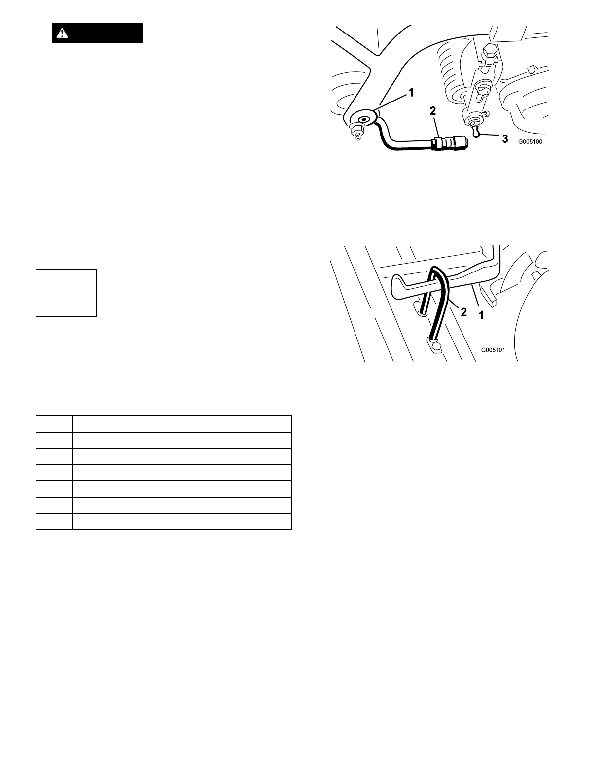
FuelLinesandConnections
•Alwaysconnectthepositive(red)batterycable
ServiceInterval:Every2,000hours/Every2years
(whichevercomesrst)
Every2,000hours/Every2years
(whichevercomesrst)
Inspectthefuellinesfordeterioration,damage,orloose
connections.
31
beforeconnectingthenegative(black)cable.
Ifcorrosionoccursattheterminals,disconnectthe
cables,negative(-)cablerst,andscrapetheclampsand
terminalsseparately.Reconnectthecables,positive(+)
cablerst,andcoattheterminalswithpetroleumjelly.
Page 32

WARNING
CALIFORNIA
Proposition65Warning
BrakeMaintenance
AdjustingtheBrakes
Batteryposts,terminals,andrelated
accessoriescontainleadandleadcompounds,
chemicalsknowntotheStateofCalifornia
tocausecancerandreproductiveharm.
Washhandsafterhandling.
Abrakeadjustmentrodislocatedoneachsideofthe
machinesothatthebrakescanbeequallyadjusted.
Adjustthebrakesasfollows:
1.Whilemovingforwardintransportspeed,pressthe
brakepedal;bothwheelsshouldlockequally.
CAUTION
Testingthebrakesinaconnedareawhere
othersarepresentcouldcauseinjury.
Alwayscheckthebrakesinawide,open-spaced,
atareawhichisfreeofotherpersonsand
obstructionsbeforeandafteradjustment.
2.Ifthebrakesdonotlockequally,disconnectthe
brakerodsbyremovingthecotterpinandclevispin
Figure39).
(
Figure39
1.Clevispinandcotterpin3.Clevis
2.Jamnut
3.Loosenthejamnutandadjusttheclevisaccordingly
(Figure39).
4.Assembletheclevistothebrakeshaft(Figure39).
5.Checktheamountoffreetravelofthebrakepedal
whentheadjustmentiscompleted.Thereshouldbe
1/2to1inch(13to26mm)travelbeforethebrake
shoesmakecontactwiththebrakedrums.Adjust,if
necessary,toachievethissetting.
6.Whilemovingforwardintransportspeed,pressthe
brakepedal;bothbrakesshouldlockequally .Adjust,
ifnecessary.
7.Itisrecommendedthatthebrakesbeburnished
annually;refertotheBreak-InPeriodsection.
32
4.Brakeshaft
Page 33

ControlsSystem
G011201
1
2
G011202
1
G011203
1
2
3
4
Maintenance
AdjustingtheRearCamshaft
Acamshaftmisalignedwiththevalvebankmaycause
thefollowing:
•NoincreaseingroundspeedintheNo.2(transport)
tractionselection
•Themowpedalwillnotstaydepressed(indetent)
withoutfootpressure.
•Slowliftofthecuttingunits
•Slowornodrivetothecuttingunits
Ifoneormoremalfunctionsoccur,loosentherear
camshaftmountingbolts(
camshaftuntiltheconditioniscorrected.Retightenthe
bolts.
Important:Readjustthemow/liftswitchand
theliftandmowpedalheightwhenthecamshaft
adjustmentiscompleted.
Figure40)andrelocatethe
Figure41
1.Transferrodguard
2.Loosenthejamnutsecuringtheyokeonthefront
ofthelongcontrolrod.Removethecotterpinand
clevispin.
3.Movetheadjustmentleverbyhandtolevelthemow
andliftpedalsandadjusttheyokeonthecontrol
roduntiltheholeintheyokelinesupwiththe
adjustmentleverhole(
Figure42).
Figure40
1.Mountingbolts
2.Camblocks
AdjustingtheLiftandMow
PedalHeight
Togainproperspooltravelinthevalvebank,adjustthe
liftandmowpedalstoequalheightsasfollows:
1.Place1,2,and3spoolsinneutral(centeroftravel)
andremovethetransferrodguardfromthefoot
panel(
Figure41).
Figure42
1.Jamnut
2.Yoke4.Adjustmentlever
3.Controlrod
LevelingtheLiftandMow
Pedals
Iftheliftandmowpedalsarenotlevelwhentheyare
intheneutralposition,anadjustmenttotheliftpivot
isrequired.
1.Loosenthenutonthebacksideoftheliftpivot
(Figure43).
33
Page 34

Figure43
G011206
2.Rotatetheeccentricscrew(Figure43)toraiseor
lowertheliftpivotspring,levelingtheliftpivotand
pedals.
3.Whileholdingthescrew ,tightenthenutlockingthe
adjustment.
AdjustingtheTractionPedal
AdjustingReverse
1.Pressdownontherearofthetractionpedal(reverse)
untiltheNo.5sectionspoolvalveiscompletely
pushedin.2.A.B.
2.Checkthedistancebetweenthebottomofthepedal
andfootrestasshownin
shouldbeapproximately3/16inch(5mm).Ifthe
distanceisgreaterorlessthan3/16inch(5mm),an
adjustmenttothetractioncontrolrodisrequired.
Proceedasfollows:
A.Removethejamnutandballjointsecuringthe
controlrod(
Figure44)tothetractionshaftpivot.
B.Loosenthejamnutssecuringtheballjoints
tothecontrolrodandadjusttheballjoints
andcontrolrodtoattainthe3/16inch(5mm)
dimensionwhenreinstalled.
Figure44.Thedistance
Tochecktheforwardandreverseoperationofthe
tractionpedal,proceedasfollows:
AdjustingForward
1.PressthetractionpedalfullyforwarduntiltheNo.
5sectionvalvespooliscompletelypulledout.The
pedalshouldcontactthepedalstop(Figure44).
AdjustingCuttingUnitLiftand
Drop
Thecuttingunitlift/dropcircuitisequippedwitha
owcontrolvalve.Thisvalveispresetatthefactoryat
approximately3-1/2turnsopen,butanadjustmentmay
berequiredtocompensatefordifferencesinhydraulic
oiltemperatures,mowingspeeds,etc.Ifanadjustment
isrequired,proceedasfollows:
Note:Allowthehydraulicoiltoreachfulloperating
temperaturebeforeadjustingtheowcontrolvalve.
1.Raisetheseatandlocatetheowcontrolvalve
mountedtothemaincontrolvalve(
Figure45).
Figure44
1.Fullyforward
2.Pedalstop
3.Reverse
4.Controlrod
Ifthepedalcontactsthestopbeforethespoolis
completelyout,orifthepedaldoesnotmakecontact
withthestop,anadjustmenttothestopisnecessary.
Proceedasfollows:
2.Loosenthehexnutsecuringthethreadedrodto
theframe.Turntheangenutontherodtoraise
orlowerthestop(rod)whilecheckingthepedal.
Retightenthenut.
Figure45
1.Flowcontrolvalve
2.Loosenthejamnutretainingtheadjustingknobon
theowcontrol.Whenlooseningthejamnut,hold
theowcontrolknobtopreventitfromrotating.
34
Page 35

3.Rotatetheknob1/4turncounterclockwiseifthe
centercuttingunitisdroppingtoolateor1/4turn
clockwiseifthecentercuttingunitisdroppingtoo
early.
4.Afterthedesiredsettinghasbeenachieved,holdthe
knobtopreventanyrotationandtightenthejamnut.
AdjustingtheLiftCylinders
Toregulatetheheightofthefrontcuttingunitswhenin
theraised(transport)position,thefrontliftcylinders
maybeadjusted.
1.Lowerthecuttingunitstotheground.
2.Loosenthejamnut,ontheclevis,ofthecuttingunit
liftcylinderthatneedstobeadjusted.
3.Disconnectthecylinderclevisfromtheliftarm.
4.Rotatetheclevisuntilthedesiredheightisattained.
5.Connectthecylinderclevistotheliftarmandtighten
thejamnut.
shorterthanthetopoftheseatreturnspringpin.
Installthebootintothemountgrooves.
5.Carefullyreleasetheseattoitsnormallydown
position,butdonotsitorapplyforceontheseat.
Thereshouldbeaslightgapbetweentheswitchand
theseatplate.
6.Locktheswitchinplacebytighteningthejamnutto
75in-lb(8N-m)againstthemountingbracket.
Important:Theswitchthreadswillbedamaged
ifthejamnutisovertightened.
7.Connectacontinuitytesterorohmmetertothe
switchterminals.Withtheseatinthedownposition
andnooneontheseat,theswitchcircuitshouldnot
havecontinuity .Ifthereiscontinuity,repeatsteps
4–6.Ifthereisnocontinuity ,proceedtostep8.
8.Sitontheseat.Theseatswitchshouldhave
continuity.Ifthereisnocontinuity,repeatsteps
Ifthereiscontinuity,proceedtostep9.
9.Plugtheswitchconnectorstogether.
4–7.
ReplacingtheSeatSwitch
1.Pivottheseatforwardandsecureitwiththesupport
rod.
2.Removethebootfromthebuttonendoftheseat
switch(Figure46)andretainitforinstallationonthe
replacementswitch.Unplugtheswitchconnectors.
Figure46
1.Tractionswitch
2.Seatswitch
3.Mow/liftswitch
ReplacingtheTractionSwitch
1.Pivottheseatforwardandsecureitwiththesupport
rod.
2.Unplugtheswitchconnectorsfromthetraction
switchinstalledinthevalvebankbonnetonthe
selectorvalvesection(
3.Loosenthejamnutandunscrewtheswitchfromthe
mountingbracket.
4.MovetheshiftselectortoNeutral.
5.Partiallyscrewthenewswitchintothebonnet.
6.Connectacontinuitytesterorohmmetertothe
switchterminalsandcontinuetoturntheswitchin
untilthereiscontinuity.Thenrotatetheswitchin
1/2turn(180degrees).
7.Tightenthejamnutto75in-lb(8N-m)againstthe
bonnet.
Important:Theswitchthreadswillbedamaged
ifthejamnutisovertightened.
8.Connectacontinuitytesterorohmmetertothe
switchterminalsandmovetheshiftselectortothe
#1and#2positions.Thereshouldnotbecontinuity
whentheshiftselectorisineitherofthesepositions.
Ifthereiscontinuity,repeatsteps5and6.
Figure46).
3.Loosenthejamnutandunscrewtheswitchfromthe
mountingbracket.
4.Screwthenewswitchthroughthemountingbracket
untiltheswitchbuttonisabout1/16inch(1.6mm)
9.MovetheshiftselectorlevertoNeutralandconnect
acontinuitytesterorohmmetertotheswitch
terminals.Theswitchshouldshowcontinuity .This
meanstheswitchisoperatingcorrectly.
10.Plugtheswitchconnectorstogether.
35
Page 36

ReplacingtheMow/LiftSwitch
G011208
1
2
3
Important:Thespooltravelforthe1,2,
and3spoolsmustbecorrectbeforethe
mow/liftswitchcanbeadjusted;referto
AdjustingtheRearCamshaft(page33).
1.Pivottheseatforwardandsecureitwiththesupport
rod.
2.Unplugtheswitchconnectorsfromtheendofthe
mow/liftswitchinstalledinthevalvebankbonnet
Figure46).
(
3.Loosenthejamnutandunscrewtheswitchfromthe
valvebankbonnet.
4.Whileholdingtheliftpedalinthefullydepressed
position(thevalvebankspoolsarefullyin)partially
screwthenewswitchintothebonnet.
5.Connectacontinuitytesterorohmmeteracross
theswitchterminalsandturntheswitchinuntil
continuityoccurs.Thenrotatetheswitchin1/2turn
(180degrees)andsecurethejamnutto75in-lb(8
N-m)againstthebonnet.
Important:Theswitchthreadswillbedamaged
ifthejamnutisovertightened.
6.Connectacontinuitytesterorohmmetertothe
switchterminalsanddepressthemowpedal.There
shouldnotbecontinuity.Ifthereiscontinuity ,repeat
4.Proceedtostep7ifthereisnocontinuity.
step
7.Presstheliftpedalandreleaseit(neutralposition).
Theswitchcircuitshouldhavecontinuity.
8.Plugtheswitchconnectorstogether.
AdjustingtheTractionReturn
Linkage
IftheshiftselectorleverdoesnotreturntoNeutralor
the#1positionfromthe#2positionwhenthemow
pedalisengaged,anadjustmenttothetractionreturn
linkageisrequired.
Figure47
1.Cableassembly3.Mow/liftcontrolrod
2.Mow/liftcontrolrodbracket
2.Movetheshiftlevertothe#1position.
3.Whileholdingthemow/liftcontrolrodintherear
position,tightentherearlocknuttoremovealmost
alloftheslackfromthecableassembly(Figure47).
Donotover-tensionthecable.
4.Tightenthefrontjamnuttolocktheadjustment.
5.Checktheoperationandreadjustasrequired.
ServicingtheSteering
Assembly
Thesteeringcabletensionshouldbeadjustedwhenever
playisfeltinthesteeringwheel.Aloosesteering
cablewillmakeitdifculttosteerinastraightline.
However,overtighteningthecablewillcauseundue
weartothepulleysandcausethecabletostretchand
failprematurely.Whenproperlytensioned,thecable
shoulddeect1/2inch(13mm)atmidspanwhen11
lbofforceisapplied.
1.Tensionthecablebysecuringthecableendhexwith
anopenendwrenchandturningthenutonthecable
endwithanotherwrench(
Figure48).
1.Loosenthefrontjamnutsecuringthecableassembly
tothemow/liftcontrolrodbracket(
Figure47).
36
Page 37
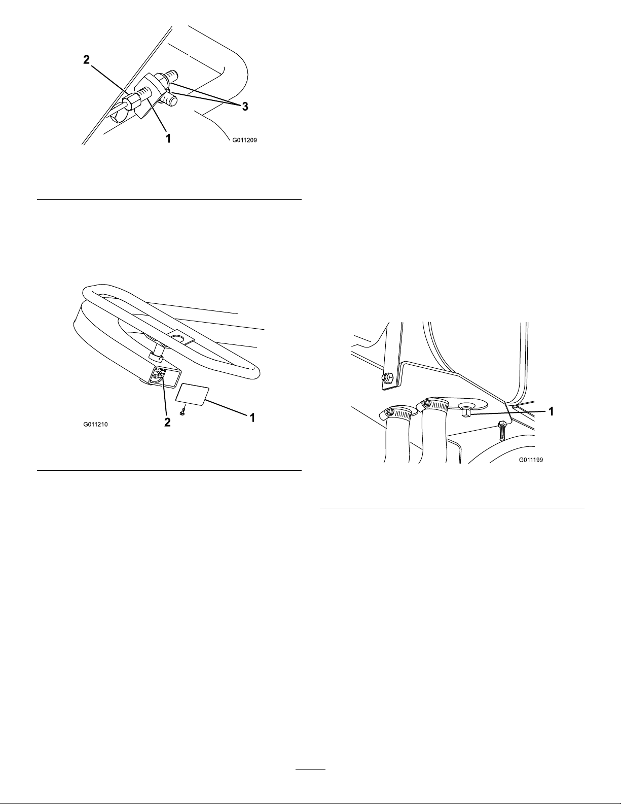
G011209
1
2
3
1.Steeringcable
G011210
1
2
G011199
1
2.Holdwithwrench
Figure48
3.Turntoremoveslack
HydraulicSystem
Maintenance
ChangingtheHydraulicOil
andFilter
ServiceInterval:Every2,000hours/Every2years
(whichevercomesrst)
Every2,000hours/Every2years
(whichevercomesrst)
2.Ifallthreadsonthecableendhavebeenused,
replacethecables.Ifnecessary,servicethepulley
andsteeringcableunderthesteeringwheelby
removingthecoverontheendofthesteering
column(Figure49).
Figure49
1.Cover
2.Pulleyandsteeringcable
Iftheoilbecomescontaminated,contactyourlocal
Torodistributorbecausethesystemmustbeushed.
Contaminatedoillooksmilkyorblackwhencompared
tocleanoil.
1.Removethedrainplugfromthereservoir(
andlethydraulicoilowintoadrainpan.Reinstall
andtightentheplugwhenhydraulicoilstops
draining.
Figure50
1.Hydraulicreservoirdrainplug
Figure50)
2.Cleantheareaaroundtheltermountingarea
(Figure51).Placeadrainpanunderthelterand
removethelter.
37
Page 38
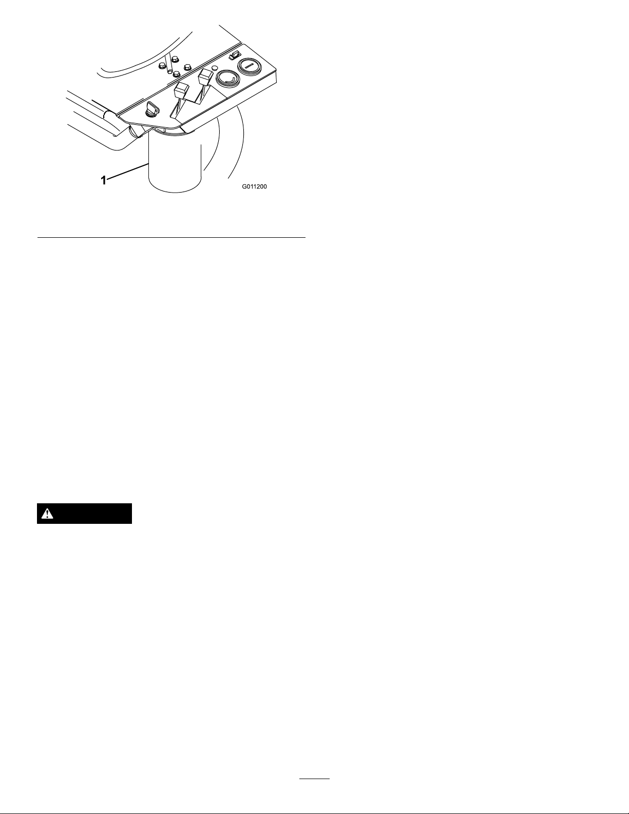
G011200
1
Figure51
1.Hydrauliclter
3.FillthereplacementlterwithMobilDTE15M
hydraulicuid.Lubricatethesealinggasket,and
handturnthelteruntilthegasketcontactsthelter
head.Tightenthelter3/4turnfurther.Thelter
shouldnowbesealed.Donotovertighten.
4.Fillthehydraulictankwithapproximately
4.5gallonsofhydraulicoil;referto
CheckingtheHydraulicFluidLevel(page20).
Checkthehydrauliclinesandhosesdailyforleaks,kinked
lines,loosemountingsupports,wear,loosettings,
weatherdeterioration,andchemicaldeterioration.Make
allnecessaryrepairsbeforeoperating.
5.Startthemachineandrunitatidlefor3to5minutes
tocirculatetheuidandremoveanyairtrappedin
thesystem.Stopthemachineandrechecktheuid
level
6.Disposeoftheusedoilproperly.
CheckingtheHydraulicLines
andHoses
WARNING
Hydraulicuidescapingunderpressurecan
penetrateskinandcauseinjury.
•Makesureallhydraulicuidhosesandlinesare
ingoodconditionandallhydraulicconnections
andttingsaretightbeforeapplyingpressureto
thehydraulicsystem.
•Keepyourbodyandhandsawayfrompin
holeleaksornozzlesthatejecthighpressure
hydraulicuid.
•Usecardboardorpapertondhydraulicleaks.
•Safelyrelieveallpressureinthehydraulicsystem
beforeperforminganyworkonthehydraulic
system.
•Getimmediatemedicalhelpifuidisinjected
intoskin.
38
Page 39

Storage
Ifyouwishtostorethemachineforalongperiodof
time,thefollowingstepsshouldbeperformedpriorto
storage:
1.Removeaccumulationsofdirtandoldgrass
clippings.Sharpenthereelsandbedknives,if
necessary;refertotheCuttingUnitOperator’ sManual.
Usearustpreventiveonbedknivesandreelblades.
Greaseandoilalllubricationpoints;referto
GreasingtheMachine(page27).
2.Blockupthewheelstoremoveanyweightonthe
tires.
3.Drainandreplacethehydraulicuidand
lterandinspectthehydrauliclinesand
ttings.Replace,ifnecessary;referto
ChangingtheHydraulicOilandFilter(page37)and
CheckingtheHydraulicLinesandHoses(page38).
4.Allfuelshouldberemovedfromthefueltank.Run
theengineuntilitstopsfromlackoffuel.Replacethe
fuellter;refertoReplacingtheFuelFilter(page31).
5.Whiletheengineisstillwarm,draintheoilfrom
thecrankcase.Rellitwithfreshoil;referto
ChangingtheEngineOilandFilter(page29).
6.Removethesparkplugs,pouroneounceofSAE
30oilintothecylinders,andcrankslowlyto
distributetheoil.Replacethesparkplugs;referto
ReplacingtheSparkPlugs(page30).
7.Cleandirtandchafffromthecylinder,cylinderhead
ns,andblowerhousing.
8.Removethebatteryandchargeitfully .Eitherstore
itontheshelforonthemachine.Leavethecables
disconnectedifitisstoredonthemachine.Store
thebatteryinacoolatmospheretoavoidquick
deteriorationofthechargeinthebattery.
9.Ifpossible,storethemachineinawarm,drylocation.
39
Page 40

Troubleshooting
Engine
Problem
Theenginelosespower.
Theenginewillnotstart.
PossibleCauseCorrectiveAction
1.Thefueltankisempty.1.Fillthefueltank.
2.Afuellineiscloggedorthereisdebris
inthefueltank.
3.Thefuellterisclogged.3.Replacethelter.
4.Theoillevelinthecrankcaseislow .
5.Theoilinthecrankcaseisincorrect.5.Replaceitwiththecorrectoil.
6.Carburetorfuelsolenoid6.Checkthesolenoidandwiring.
7.Thethrottlecableissetincorrectly.7.Repairasnecessary .
8.Thechokeisclosed.8.Readjustthechoke.
9.Theaircleanerelementisplugged.9.Replacetheelementandserviceit
10.Thecarburetormalfunctions.
11.Theignitionmalfunctions.
12.Thecoolingnsarepluggedwithdebris
ortheengineisoverheating.
13.Theenginehasaninternalmalfunction.
14.Thepumpcouplingisloose.14.Repairorreplacethecoupling.
15.Thehydraulicsystemismalfunctioning.15.Refertohydraulictroubleshooting
1.Theignitionsystemisfaulty .
2.Thefueltankisempty.2.Fillthefueltank.
3.Thestartersystemismalfunctioning.3.Checktheconnections,solenoid,
4.Carburetorfuelsolenoid4.Checkthesolenoidandwiring.
2.Cleanthefueltank.Useclean
gasoline.
4.Addoiltotheproperlevel.Checkthe
levelmorefrequently .
morefrequently .
10.Repairasnecessary.
11.Repairasnecessary.
12.Cleanthens.Repairtheengineas
necessary.
13.Repairasnecessary.
below.
1.Repairasnecessary .
startermotor,andignitionswitch.
Hydraulic
Problem
Thereisnogroundspeedincreaseinthe
#2selection.
Inthehydraulicsystemthereisno#1or
reversetractionspeed.The#2speedis
normal.
PossibleCauseCorrectiveAction
1.Thecontrolleverismisadjusted.1.Adjustthecontrollever .
2.Therearcamshaftismisadjusted.
3.Themow/liftlinkageisbindingorthere
isabrokenliftpivotspring.
4.Therearewrongdetentpartsinthe#4
spool.
5.The#2or#3spoolreliefvalvesare
stuckopen.(ThereeldriveRPMwill
alsobelowonthe#1or#3cuttingunit).
1.Thediscsealbetweenthe#3and#4
valvesectionsisdamagedormissing.
2.Thepoppetinsidethe#4spoolisstuck
openoroffitsseat.
3.Thetractionreliefcartridgeinthe#4
spoolsectionisopen.
4.Atractionmotorlacksefciency .There
isuidleakingpasttheinternalgears.
5.Thehydraulicpumplacksefciency.
Thereisuidleakingpasttheinternal
gears.
2.Adjustitbymovingtherightendorthe
rearcamshaftforwardortheleftend
rearward.
3.Lubricateorrepairthemachine.
4.Removethevalvebankandrepairthe
#4spoolassembly .
5.Removeandrepairorreplacetherelief
cartridge.
1.Removethevalvebankandreplace
thediscseal.
2.Removethevalvebankandrepairthe
#4spoolsection.
3.Removethereliefcartridge.Repairor
replaceit.
4.T esttoidentifythefaultymotor.Repair
orreplacethemotor.
5.T esttoverifyadiagnosis.Repairor
replacethepump.
40
Page 41

Problem
PossibleCauseCorrectiveAction
Thereisnotractionoritisslowinall
selectionsandthereelsareaffected.
Theshiftleverisbinding.1.The#4spooldetentassemblyis
Allthreecuttingunitsraiseandlowertoo
slowly.
Thecenter(#1)cuttingunitisdroppingtoo
lateortooearly.
Thefrontcuttingunitsaretoohighortoo
lowwhentheyareintheraised(transport)
position.
Thecuttingunitslifttooslowly.
Thecentercuttingunit(#1)reeloperates
intheraisedposition.
1.Theoillevelinthereservoirislow.1.Addoiltotheproperlevel.
2.Theshiftleverbracketisloose.2.Adjustandtightentheshiftlever.
3.Therearcamshaftismisadjusted.3.Adjustthecamshaft.
4.Theenginelackspower.4.Repairasnecessary .
lackinglubrication.
1.Theliftcylinderandlinkagesare
bindingduetolackoflubrication.
1.Theowcontrolvalveismisadjusted.
1.Thefrontliftcylindersaremisadjusted.
1.Therearcamshaftismisadjusted.1.Adjustthecamshaft.
2.The#1spooltravelisrestrictedbythe
mow/liftswitch.
3.Theliftcheckpoppetinthe#1spool
sectionisstuckpartiallyclosed.
1.Therearcamshaftismisadjusted.The
#3spoolistoofaroutofthebody.
2.Thebrazedtubeassemblyonthe#3
spoolsectionisrestricted.
3.Thevalvereturnportbetweenthe#3
spoolsectionandtheright-handcover
isrestricted.
1.Removethevalvebank.Disassemble
thedetentassemblyandrepairit.
1.Lubricatemorefrequently .
1.Adjustthevalve.
1.Adjustthecylinders.
2.Adjusttheswitch.
3.Removetheliftcheckandrepairor
replaceit.
1.Adjustedthecamshaft.
2.Removetherestriction.
3.Disassemblythecoverandremovethe
restriction.
Thecuttingunitsdropduringtransport
(betweengreens).
Thecuttingunitsdropwhilethemachine
isstored(overnight).
Oneormorecuttingunitsaresloworthere
isnoreeldrivenaction.
1.Aliftcylinderisleakinginternally.
2.Theliftcheckplugsealsinthe#1spool
bodyaredamaged.
3.Adetentstudislooseinthe#2spool.3.Removetheadjustmentcapfromthe
4.The#1spoolislooseinthevalvebody
anduidisbypassing.
1.Thisisanormalcondition.1.Norepairisnecessary.
1.Thebedknifetoreeladjustmentistoo
tight.
2.Thereelbearingsaretight.2.Repairasnecessary .
3.Therearcamshaftismisadjusted.3.Adjustthecamshaft.
4.Thepoppetinareliefcartridgeisoff
seat.
5.Animpropersuctionline(s)isinstalled.
Thelinecollapsed.
6.Alinettinghasablockage.
7.Amotorisexcessivelyworn.
8.The#1cuttingunithasslowreelRPM.8.Checktheliftcylindersforinternal
1.Raisetheunitsandblockthemup.
Removethelinesfromthebrazed
tubeandremovetheblocks.Theline
thatleaksuidisattachedtothebad
cylinder.Repairthecylinder.
2.Removetheliftcheckplugs.Replace
theo-ringassemblies.
#2spoolbonnet.Tightenthestudwith
ascrewdriver.
4.Replacethespoolvalveassembly.
1.Adjustperthecuttingunitoperator’s
manual
4.Removeandrepairorreplacetherelief
cartridge.
5.Removethesuctionlineandreplace
withgenuineT oroparts.
6.Repairasnecessary .
7.T esttoverify .Repairorreplacethe
motor.
leakage.Repairorreplacethecylinder.
41
Page 42

Problem
9.Thepumpisexcessivelyworn.
10.Aspoolislooseinthevalvebody.Fluid
isleakingpastthespool.
11.Asteelpressurelineisdamagedand
owisrestricted(frontcuttingunits
only).
12.Theuidlevelislowenoughtoaffect
thetotalmachineperformance.
PossibleCauseCorrectiveAction
9.T exttoverify .Repairorreplacethe
pump.
10.Replacethespoolvalveassembly .
11.Replacetheline.
12.Adduid
Thereeldrivepressurelinespulsate
duringoperation.
Themowpedalwillnotstaydownunless
itishelddownwithyourfoot(the#2spool
isnotinDetent).
Electrical
Problem
Theenginestarts(butshouldnot)when
theshiftselectorisingear.
Theenginestarts(butshouldnot)when
themowpedalisdepressedandthereels
areengaged.
Theenginestarts(butshouldnot)when
theoperatorisnotontheseat.
Theenginefailstocrank,regardlessofthe
shiftselectorormowpedalposition.
1.Thisisanormalcondition.Itwillvary
fromlinetoline.
1.Therearcamshaftismisadjusted.1.Adjustthecamshaft.
2.The#2spooldetentismalfunctioning.
PossibleCauseCorrectiveAction
1.Thetractionswitchisadjusted
incorrectlyorisdamaged.
1.Themow/liftswitchisadjusted
incorrectlyorisdamaged.
1.Theseatswitchisadjustedincorrectly
orisdamaged.
1.Themow/liftswitch,tractionswitch,
and/orseatswitchareadjusted
incorrectlyoraredamaged.
2.Thebatteryterminalsarecorroded.
3.Themow/liftortractionswitchwires
areloose.
4.Thebatteryisdead.
5.Asolenoidisdamaged.5.Replacethesolenoid.
6.Theignitionswitchisdamaged.6.Replacetheignitionswitch.
7.Thestarterisdamaged.7.Replaceorrepairthestarter.
8.Theengineisseized.8.Repairtheengine.
9.Thekeyswitch,voltmeter ,orsolenoid
wiresareloose.
10.Theoperatorisnotontheseat.
1.Norepairisnecessary .
2.Removeandrepairit.
1.RefertoReplacingtheTractionSwitch.
1.RefertoReplacingtheMow/LiftSwitch.
1.RefertoReplacingtheSeatSwitch
1.RefertoReplacingtheTractionSwitch,
ReplacingtheMow/LiftSwitch,and/or
ReplacingtheSeatSwitch.
2.Cleantheterminals.
3.Checkthewiresandconnectthem
properly.
4.Chargeorreplacethebattery .
9.Connectthewires.
10.Sitontheseat.
Theenginecranksbutdoesnotstartwhen
theshiftselectorandmowpedalarein
neutral.
Theenginedoesnotstopwhenthe
mowpedalisdepressed(thereelsare
engaged)asyougetoffoftheseat.
1.Thecauseofthisproblemisunrelated
totheinterlockwiringsystem.
2.Therearcamshaftismisadjusted.2.Adjustthecamshaft.
3.Theengineorrectierplugisloose.3.Connectthewire.
4.The“I”terminalwireofkeyswitchis
loose.
5.Thereisenginetroubleorthefueltank
isempty .
6.Theparkingbrakekillrelayisdamaged.6.Replacetherelay.
1.Themow/liftorseatswitchisadjusted
incorrectlyorisdamaged.
2.Theseatreturnpinspringisbroken,
missing,orjammeddown.
3.Theseatpivotfailstorotatefreely.
1.Allinterlockswitchesareokay .Proceed
tonextcause.
4.Connectthewire.
5.Determinetheproblemandcorrectit.
1.RefertoReplacingtheMow/LiftSwitch
orReplacingtheSeatSwitch.
2.Replace,loosen,andlubricatethe
partssothatthepinoperatesfreely.
3.Loosenandlubricatetheseatpivotpin
toensurefreemovement.
42
Page 43

Problem
PossibleCauseCorrectiveAction
Theenginedoesnotstopwhentheshift
selectorisingearasyougetoffofthe
seat.
Theengineseemsto“cutout”toomuch
duringtransport.(Somecutoutisnormal.)
Theenginedoesnotcontinuetorunwhen
sittingontheseatandtheshiftselector
isplacedingearorthemowpedalis
depressed.
Theenginestopsregardlessoftheshift
selectorormowpedalpositionevenifboth
areinNeutral)asyougetoffoftheseat.
Theenginedoesnotstopwhentheignition
keyisrotatedtotheOffposition.
1.Thetractionorseatswitchisadjusted
incorrectlyorisdamaged.
2.Theseatreturnpinspringisbroken,
missing,orjammeddown.
3.Theseatpivotfailstorotatefreely.
1.Theseatifliftingoffoftheseatswitch
buttontooeasily.
1.Theseatswitchisadjustedincorrectly
orisdamaged.
2.Theseatreturnpinspringisjammed
intheupposition.
1.Themow/liftswitchand/ortraction
switchareadjustedincorrectlyorare
damaged.
2.Themow/liftand/ortractionswitch
wiresareloose.
3.Thetractionswitchextensionplug
wiresareloose.
4.The“B”terminalwireofthekeyswitch
isloose.
1.Theignitionswitchconnectionisloose.1.Pushtheconnectorontotheignition
2.Theignitionswitchisdamaged.2.Replacetheignitionswitch.
3.Thewiresintheconnectorhave
shorted.
4.Theenginetimingorcarburetor
adjustmentisincorrect.
1.RefertoReplacingtheTractionSwitch
orReplacingtheSeatSwitch.
2.Replace,loosen,andlubricatethe
partssothatthepinoperatesfreely.
3.Loosenandlubricatetheseatpivotpin
theensurefreemovement.
1.Adjusttheseatswitchorinstructthe
operatortositbackintheseatduring
transport.
1.RefertoReplacingtheSeatSwitch.
2.Loosenandlubricatethejammedparts
sothatthepinoperatesfreely.Replace
thespringifitisdamaged.
1.RefertoReplacingtheMow/LiftSwitch
andReplacingtheTractionSwitch.
2.Connectthewires.
3.Connectthewires.
4.Connectthewires.
switchterminals.
3.Repairtheaffectedwires.
4.Adjustthecarburetororenginetiming.
Thebatterydoesnotcharge.
1.Afuseisblownormissing.1.Installanewfuse.
2.Theelectricalsystemhasaloosewire.
3.Theregulatororenginechargingcircuit
isdamaged.
2.Checkallconnectionsandmakeall
necessaryrepairs.
3.Installanewregulatororrepairthe
enginechargingcircuit.
43
Page 44

Schematics
G01121 1
ElectricalSchematic(Rev.A)
44
Page 45

G011212
HydraulicSchematic(Rev.A)
45
Page 46

Notes:
46
Page 47

Notes:
47
Page 48

TheToroTotalCoverageGuarantee
ALimitedWarranty
ConditionsandProductsCovered
TheT oro
toanagreementbetweenthem,jointlywarrantyourT oroCommercial
product(“Product”)tobefreefromdefectsinmaterialsorworkmanship
fortwoyearsor1500operationalhours*,whicheveroccursrst.This
warrantyisapplicabletoallproductswiththeexceptionofAerators
(refertoseparatewarrantystatementsfortheseproducts).Wherea
warrantableconditionexists,wewillrepairtheProductatnocosttoyou
includingdiagnostics,labor,parts,andtransportation.Thiswarranty
beginsonthedatetheProductisdeliveredtotheoriginalretailpurchaser.
*Productequippedwithanhourmeter.
®
Companyanditsafliate,T oroWarrantyCompany,pursuant
InstructionsforObtainingWarrantyService
YouareresponsiblefornotifyingtheCommercialProductsDistributoror
AuthorizedCommercialProductsDealerfromwhomyoupurchasedthe
Productassoonasyoubelieveawarrantableconditionexists.Ifyouneed
helplocatingaCommercialProductsDistributororAuthorizedDealer,or
ifyouhavequestionsregardingyourwarrantyrightsorresponsibilities,
youmaycontactusat:
CommercialProductsServiceDepartment
ToroWarrantyCompany
811 1LyndaleAvenueSouth
Bloomington,MN55420-1196
E-mail:commercial.warranty@toro.com
OwnerResponsibilities
AstheProductowner,youareresponsibleforrequiredmaintenance
andadjustmentsstatedinyourOperator’sManual.Failuretoperform
requiredmaintenanceandadjustmentscanbegroundsfordisallowinga
warrantyclaim.
ItemsandConditionsNotCovered
Notallproductfailuresormalfunctionsthatoccurduringthewarranty
periodaredefectsinmaterialsorworkmanship.Thiswarrantydoesnot
coverthefollowing:
•Productfailureswhichresultfromtheuseofnon-T ororeplacement
parts,orfrominstallationanduseofadd-on,ormodiednon-Toro
brandedaccessoriesandproducts.Aseparatewarrantymaybe
providedbythemanufactureroftheseitems.
•Productfailureswhichresultfromfailuretoperformrecommended
maintenanceand/oradjustments.Failuretoproperlymaintainyour
ToroproductpertheRecommendedMaintenancelistedinthe
Operator’sManualcanresultinclaimsforwarrantybeingdenied.
•ProductfailureswhichresultfromoperatingtheProductinan
abusive,negligentorrecklessmanner.
•Partssubjecttoconsumptionthroughuseunlessfoundtobe
defective.Examplesofpartswhichareconsumed,orusedup,during
normalProductoperationinclude,butarenotlimitedto,brakes
padsandlinings,clutchlinings,blades,reels,bedknives,tines,
sparkplugs,castorwheels,tires,lters,belts,andcertainsprayer
componentssuchasdiaphragms,nozzles,andcheckvalves,etc.
•Failurescausedbyoutsideinuence.Itemsconsideredtobeoutside
inuenceinclude,butarenotlimitedto,weather,storagepractices,
contamination,useofunapprovedcoolants,lubricants,additives,
fertilizers,water,orchemicals,etc.
•Normalnoise,vibration,wearandtear,anddeterioration.
•Normal“wearandtear”includes,butisnotlimitedto,damageto
seatsduetowearorabrasion,wornpaintedsurfaces,scratched
decalsorwindows,etc.
Parts
Partsscheduledforreplacementasrequiredmaintenancearewarranted
fortheperiodoftimeuptothescheduledreplacementtimeforthatpart.
Partsreplacedunderthiswarrantyarecoveredforthedurationofthe
originalproductwarrantyandbecomethepropertyofT oro.Torowill
makethenaldecisionwhethertorepairanyexistingpartorassemblyor
replaceit.T oromayuseremanufacturedpartsforwarrantyrepairs.
NoteRegardingDeepCycleBatteryWarranty:
Deepcyclebatterieshaveaspeciedtotalnumberofkilowatt-hoursthey
candeliverduringtheirlifetime.Operating,recharging,andmaintenance
techniquescanextendorreducetotalbatterylife.Asthebatteriesinthis
productareconsumed,theamountofusefulworkbetweencharging
intervalswillslowlydecreaseuntilthebatteryiscompletelywornout.
Replacementofwornoutbatteries,duetonormalconsumption,isthe
responsibilityoftheproductowner.Batteryreplacementmayberequired
duringthenormalproductwarrantyperiodatowner’sexpense.
MaintenanceisatOwner’sExpense
Enginetune-up,lubricationcleaningandpolishing,replacementof
ItemsandConditionsNotCoveredlters,coolant,andcompleting
RecommendedMaintenancearesomeofthenormalservicesT oro
productsrequirethatareattheowner’sexpense.
GeneralConditions
RepairbyanAuthorizedT oroDistributororDealerisyoursoleremedy
underthiswarranty.
NeitherTheToroCompanynorToroWarrantyCompanyisliablefor
indirect,incidentalorconsequentialdamagesinconnectionwiththe
useoftheT oroProductscoveredbythiswarranty,includingany
costorexpenseofprovidingsubstituteequipmentorserviceduring
reasonableperiodsofmalfunctionornon-usependingcompletion
ofrepairsunderthiswarranty.ExceptfortheEmissionswarranty
referencedbelow,ifapplicable,thereisnootherexpresswarranty.
Allimpliedwarrantiesofmerchantabilityandtnessforusearelimitedto
thedurationofthisexpresswarranty.Somestatesdonotallowexclusions
ofincidentalorconsequentialdamages,orlimitationsonhowlongan
impliedwarrantylasts,sotheaboveexclusionsandlimitationsmaynot
applytoyou.
Thiswarrantygivesyouspeciclegalrights,andyoumayalsohaveother
rightswhichvaryfromstatetostate.
Noteregardingenginewarranty:
TheEmissionsControlSystemonyourProductmaybecoveredby
aseparatewarrantymeetingrequirementsestablishedbytheU.S.
EnvironmentalProtectionAgency(EP A)and/ortheCaliforniaAir
ResourcesBoard(CARB).Thehourlimitationssetforthabovedonot
applytotheEmissionsControlSystemWarranty .RefertotheEngine
EmissionControlW arrantyStatementprintedinyourOperator’sManual
orcontainedintheenginemanufacturer’sdocumentationfordetails
CountriesOtherthantheUnitedStatesorCanada
CustomerswhohavepurchasedT oroproductsexportedfromtheUnitedStatesorCanadashouldcontacttheirT oroDistributor(Dealer)toobtain
guaranteepoliciesforyourcountry ,province,orstate.IfforanyreasonyouaredissatisedwithyourDistributor’sserviceorhavedifcultyobtaining
guaranteeinformation,contacttheT oroimporter.Ifallotherremediesfail,youmaycontactusatT oroWarrantyCompany.
374-0253RevA
 Loading...