

Page 1
FormNo.3367-393RevA
11and14BladeCuttingUnits
Greensmaster
®
Flex18andFlex21Traction
Units
ModelNo.04202—SerialNo.311000001andUp
ModelNo.04206—SerialNo.311000001andUp
ModelNo.04207—SerialNo.311000001andUp
ModelNo.04208—SerialNo.311000001andUp
ToregisteryourproductordownloadanOperator'sManualorPartsCatalogatnocharge,gotowww.T oro.com.OriginalInstructions(EN)
Page 2
ThisproductcomplieswithallrelevantEuropean
directives,fordetailspleaseseetheseparateproduct
specicDeclarationofConformity(DOC)sheet.
injuryordeathifyoudonotfollowtherecommended
precautions.
Introduction
Thisreel-bladelawnmowerismountedtoawalkbehind
machineandisintendedtobeusedbyprofessional,hired
operatorsincommercialapplications.Itisprimarily
designedforcuttinggrassonwell-maintainedlawnsin
parks,golfcourses,sportselds,andoncommercial
grounds.Itisnotdesignedforcuttingbrush,mowing
grassandothergrowthalongsidehighways,orfor
agriculturaluses.
Readthisinformationcarefullytolearnhowtooperate
andmaintainyourproductproperlyandtoavoidinjury
andproductdamage.Youareresponsibleforoperating
theproductproperlyandsafely .
YoumaycontactTorodirectlyatwww.Toro.comfor
productandaccessoryinformation,helpndinga
dealer,ortoregisteryourproduct.
Wheneveryouneedservice,genuineToroparts,or
additionalinformation,contactanAuthorizedService
DealerorToroCustomerServiceandhavethemodel
andserialnumbersofyourproductready.
identiesthelocationofthemodelandserialnumbers
ontheproduct.Writethenumbersinthespace
provided.
Figure1
Figure2
1.Safetyalertsymbol
Thismanualuses2otherwordstohighlightinformation.
Importantcallsattentiontospecialmechanical
informationandNoteemphasizesgeneralinformation
worthyofspecialattention.
Contents
Introduction.................................................................2
Safety...........................................................................3
SafetyandInstructionalDecals.............................3
Operation.....................................................................4
AdjustingtheRearRoller......................................4
AdjustingtheBedknifetotheReel........................4
AdjustingtheHeightofCut..................................5
AdjustingtheCut-OffBar....................................6
SettingtheMachinetoMatchTurf
Conditions.......................................................7
Maintenance.................................................................9
SeparatingtheCuttingUnitfromtheTraction
Unit..................................................................9
ServicingtheBedbar...........................................10
BacklappingtheReel..........................................10
Figure1
1.Locationofthemodelandserialnumbers
ModelNo.
SerialNo.
Thismanualidentiespotentialhazardsandhas
safetymessagesidentiedbythesafetyalertsymbol
(Figure2),whichsignalsahazardthatmaycauseserious
©2010—TheT oro®Company
8111LyndaleAvenueSouth
Bloomington,MN55420
Contactusatwww.Toro.com.
2
PrintedintheUSA.
AllRightsReserved
Page 3
Safety
Hazardcontrolandaccidentpreventionare
dependentupontheawareness,concern,and
propertrainingofthepersonnelinvolvedinthe
operation,transport,maintenance,andstorageof
themachine.Improperuseormaintenanceofthe
machinecanresultininjuryordeath.Toreduce
thepotentialforinjuryordeath,complywiththe
followingsafetyinstructions.
•Read,understand,andfollowallinstructionsinthe
tractionunitandcuttingunitoperatorsmanual’s
beforeoperatingthecuttingunit.
•Neverallowchildrentooperatethetractionunitor
cuttingunits.Donotallowadultstooperatetraction
unitorcuttingunitswithoutproperinstruction.
Onlytrainedoperatorswhohavereadthismanual
shouldoperatethetractionunitorcuttingunits.
•Neveroperatethecuttingunitswhenunderthe
inuenceofdrugsoralcohol.
sneakersorshorts.Also,donotwearloosetting
clothingwhichcouldgetcaughtinmovingparts.
Alwayswearlongpantsandsubstantialshoes.
Wearingsafetyglasses,safetyshoesandahelmetis
advisableandrequiredbysomelocalordinancesand
insuranceregulations.
•Removealldebrisorotherobjectsthatmightbe
pickedupandthrownbythecuttingunitreelblades.
Keepallbystandersawayfromtheworkingarea.
•Ifthecuttingbladesstrikeasolidobjectortheunit
vibratesabnormally,stopandshuttheengineoff.
Checkcuttingunitfordamagedparts.Repairany
damagebeforerestartingandoperatingthecutting
unit.
•Besurecuttingunitsareinsafeoperatingcondition
bykeepingnuts,boltsandscrewstight.
•Performonlythosemaintenanceinstructions
describedinthismanual.Ifmajorrepairsare
everneededorassistanceisdesired,contactan
AuthorizedToroDistributor.
•Lightningcancausesevereinjuryordeath.If
lightningisseenorthunderisheardinthearea,do
notoperatethemachine;seekshelter.
•Keepallshieldsandsafetydevicesinplace.Ifa
shield,safetydeviceordecalisillegibleordamaged,
repairorreplaceitbeforeoperationiscommenced.
Alsotightenanyloosenuts,bolts,andscrewsto
ensurecuttingunitisinsafeoperatingcondition.
•Alwayswearsubstantialshoes.Donotoperate
cuttingunitswhilewearingsandals,tennisshoes,
SafetyandInstructionalDecals
Safetydecalsandinstructionsareeasilyvisibletotheoperatorandarelocatednearanyareaof
potentialdanger.Replaceanydecalthatisdamagedorlost.
•Toensureoptimumperformanceandsafety,always
purchasegenuineTororeplacementpartsand
accessoriestokeeptheToroallTORO.Neveruse
"will-t"replacementpartsandaccessories
madebyothermanufacturers.Lookforthe
Torologotoassuregenuineness.Usingunapproved
replacementpartsandaccessoriescouldvoidthe
warrantyofTheToroCompany.
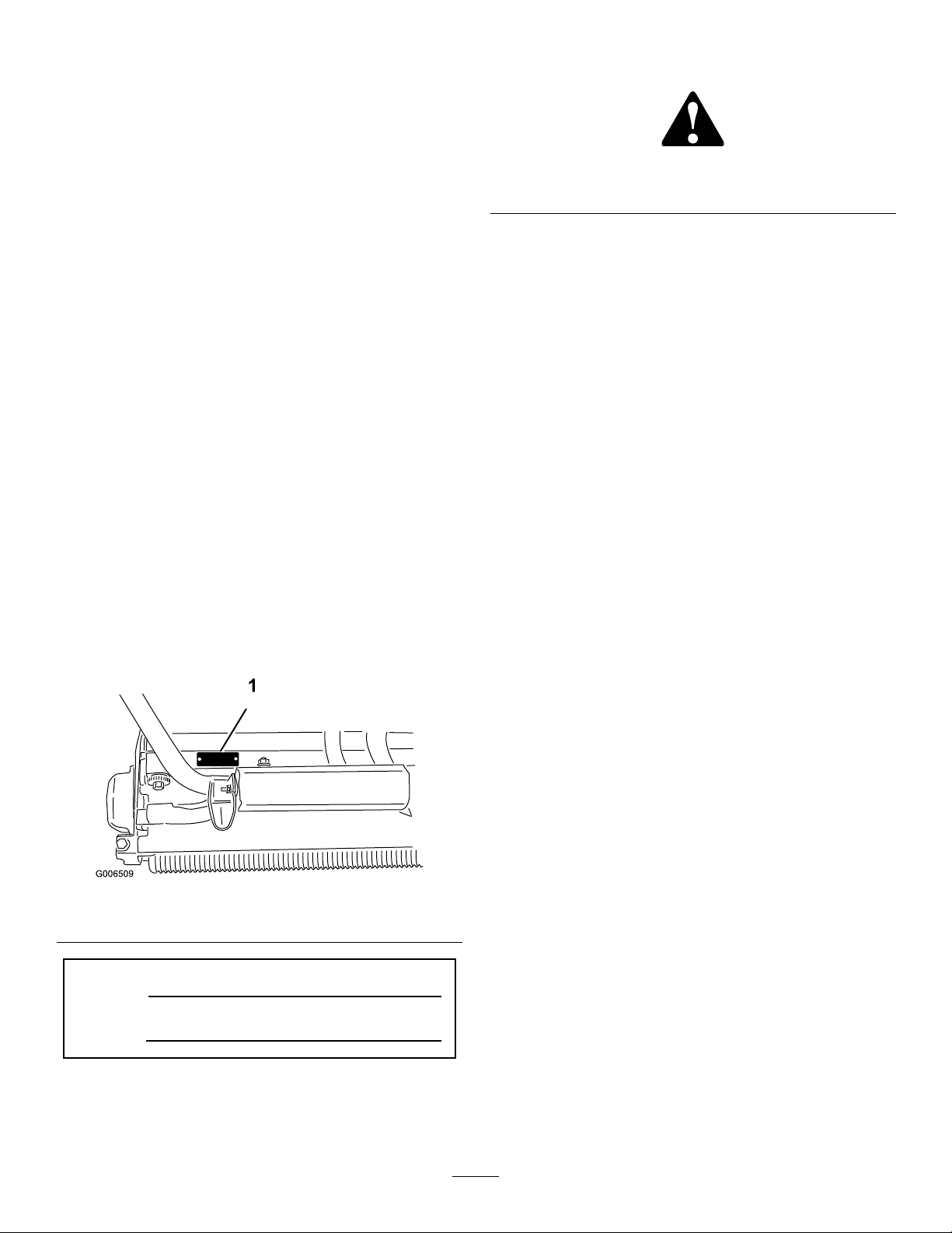
93-8064
1.Warning—readtheinstructionsbeforeservicingor
performingmaintenance.
2.Cuttinghazardoffootorhand—stoptheengineandwait
formovingpartstostop.
3
Page 4
Operation
Note:Determinetheleftandrightsidesofthe
machinefromthenormaloperatingposition.
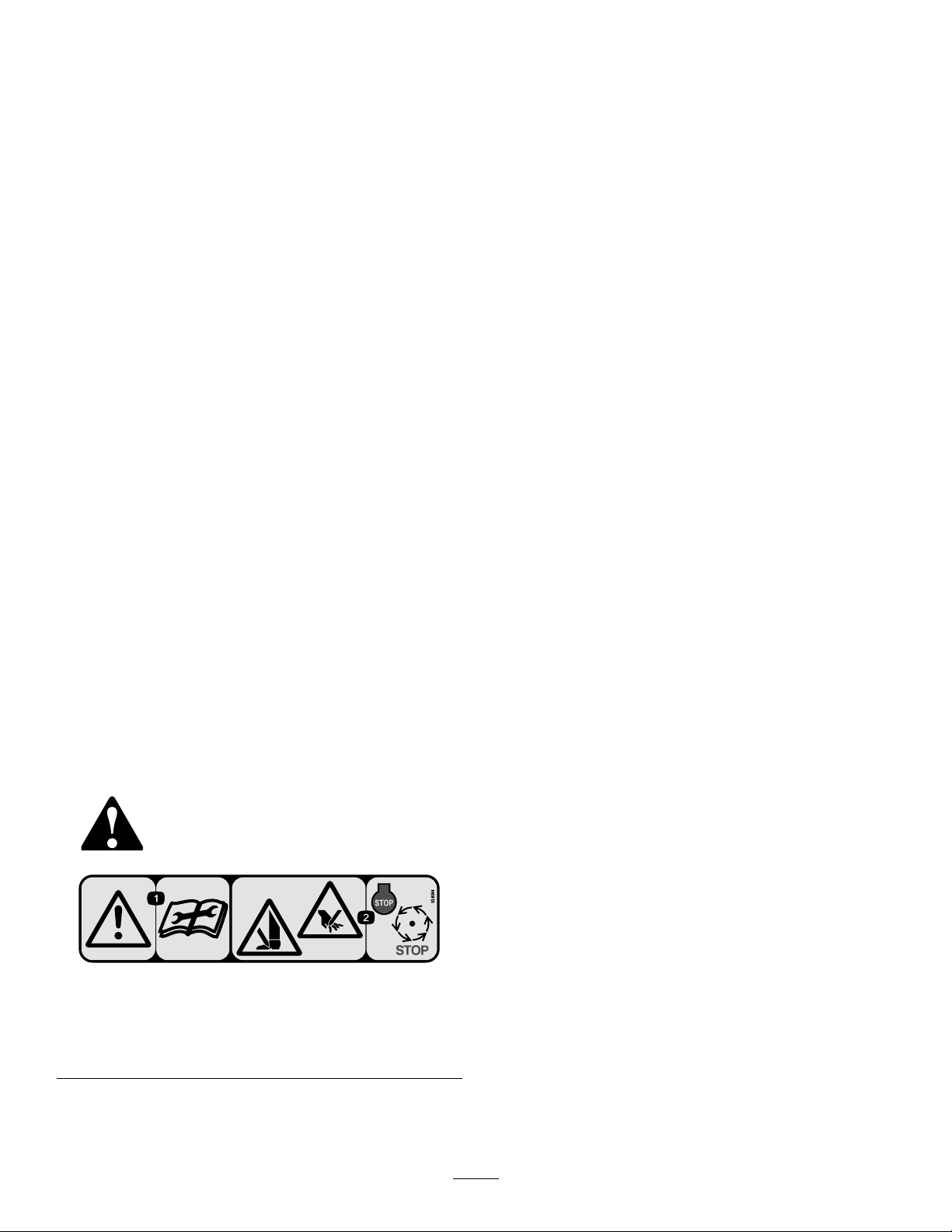
AdjustingtheRearRoller
1.Adjusttherearrollerbracketstotheloworhigh
positiondependingondesiredheightofcutrange
Figure3andFigure4).
(
•Positionthespacerabovethesideplate
mountingange(factorysetting)whenheight
ofcutsettingsrangefrom1/16to1/4inch(1.5
to6.3mm)(Figure3).
•Placespacersontoscrewsonrollerbrackets.
•Re-securerollerbracketandspacersto
undersideofsideplatemountingangeswith
nutspreviouslyremoved.
3.Verifythatthebedknifetoreelcontactiscorrect.
Tipmowertoexposefrontandrearrollersand
bedknife.
Note:Thepositionoftherearrollertothe
reeliscontrolledbythemachiningtolerances
oftheassembledcomponentsandparallelingis
notrequired.Alimitedamountofadjustmentis
possiblebysettingthecuttingunitonasurface
plateandlooseningthesideplatemountingbolts
Figure5).Adjustandre-tightenbolts.
(
Figure3
1.Spacer
2.Sideplatemountingange
•Positionthespacerbelowthesideplate
mountingangewhenheightofcutsettings
rangefrom1/8"to1"(
1.Sideplatemountingange
2.Spacer
3.Rollerbracket
Figure4
3.Rollerbracket
Figure4).
Figure5
1.Sideplatemountingbolts
Important:Wheneverthecuttingunithasto
betippedtoexposebedknife/reel,propuprear
ofcuttingunittomakesurenutsonbackend
ofbedbaradjustingscrewsarenotrestingon
worksurface.
AdjustingtheBedknifetothe
Reel
Bedknifetoreeladjustmentisaccomplishedby
looseningortighteningbedbaradjustingscrews,located
ontopofmower.
2.Toadjustrearrollerproceedasfollows:
•Raiserearofcuttingunitandplaceablock
underbedknife.
•Remove(2)nutssecuringeachrollerbracket
andspacertoeachsideplatemountingange.
•Lowerrollerandscrewsfromsideplate
mountingangesandspacers.
1.Positionmachineonaat,levelworksurface.
2.Makesurereelcontactisremovedbyturningbedbar
adjustingscrewscounterclockwise(Figure6).
4
Page 5

tothebedknife(Figure7).Itshouldbepossible
tocutpaperwithminimumcontactbetweenthe
bedknifeandthereelblades.Shouldexcessivereel
dragbeevidentitwillbeeithernecessarytobacklap
orregrindthecuttingunittoachievethesharp
edgesneededforprecisioncutting(seeTororeel
sharpeningmanual).
Figure6
1.Bedbaradjustingscrew
3.Tiltmoweronbacktoexposebedknifeandreel.
Note:Whentiltingthecuttingunitback,make
surethecenterofthecuttingunitisblockedupso
thebedbaradjusterscrewsarenotsupportingthe
cuttingunit.Restingthecuttingunitonthebedbar
adjustingscrewswillgiveafalsereel-to-bedknife
contactwhenthecuttingunitisloweredbackto
level.
4.Atoneendofreel,insertalongstripofnewspaper
betweenreelandbedknife(
Figure7).Whileslowly
rotatingreelforward,turnbedbaradjustingscrew
clockwise(onsameendofreel)(Figure6),one
clickatatime,untilpaperispinchedlightly ,when
insertedfromthefront,paralleltothebedknife.A
slightdragwillbenotedasthepaperispulled.
AdjustingtheHeightofCut
Forheightsofcutgreaterthan.500inch(12.7mm),the
highheightofcutkitmustbeinstalled.
1.Loosenlocknutssecuringheight-of-cutarmsto
cuttingunitsideplates(
Figure8).
Figure7
Note:Eachtimeadjustingscrewisrotatedone
clickclockwise,thebedknifemoves.0007inch
(.017mm)closertoreel.Donotovertightenthe
adjustingscrews.
5.Checkforlightcontactatotherendofreelusing
paperandadjustasrequired.
6.Afteradjustmentisaccomplished,checktosee
ifreelcanpinchpaperwheninsertedfromthe
frontandcutpaperwheninsertedatarightangle
Figure8
1.Rearrollerbracket3.Locknut
2.Height-of-cutarm
4.Adjustingscrew
2.Loosennutongaugebar(Figure9)andset
adjustingscrewtodesiredheight-of-cut.Distance
betweenbottomofscrewheadandfaceofbaris
height-of-cut.
Figure9
1.Gaugebar
2.Heightadjustingscrew
3.Nut
5
Page 6

3.Hookscrewheadoncuttingedgeofbedknifeand
restrearendofbaronrearroller(Figure10).
4.Rotateadjustingscrewuntilrollercontactsfrontof
gaugebar.Adjustbothendsofrolleruntilentire
rollerisparalleltothebedknife.
Important:Whensetproperly,therearand
frontrollerswillcontactthegaugebarandthe
screwwillbesnugagainstthebedknife.This
ensuresthattheheight-of-cutisidenticalat
bothendsofthebedknife.
Figure10
1.Gaugebar
Figure11
1.Cut-offbar
2.Insert.060inch(1.5mm)feelergaugebetweentop
ofreelandbarandtightenscrews.Ensurebarand
reelareequaldistanceapartacrosscompletereel.
Note:Thebarisadjustabletocompensatefor
changesinturfconditions.Thebarshouldbe
adjustedclosertoreelwhenturfisextremelydry.
Bycontrast,adjustbarfurtherawayfromreelwhen
turfconditionsarewet.Thebarshouldbeparallel
toreeltoensureoptimumperformanceandshould
beadjustedwheneverreelissharpenedonareel
grinder.
5.Tightennutstosecureadjustment.Donot
overtightennut.Tightenenoughtoremoveplay
fromwasher.
Note:Usethefollowingcharttodeterminewhich
bedknifeisbestsuitedforthedesiredheightofcut.
AdjustingtheCut-OffBar
Adjustcut-offbartoassureclippingsarecleanly
dischargedfromthereelarea:
1.Loosenscrewssecuringtopbar(Figure11)to
cuttingunit.
6
Page 7

SettingtheMachinetoMatchTurfConditions
Usethefollowingtabletosetthemachinetomatchturfconditions.
FlexGreensmowerCuttingUnitSet-upMatrix
Bedbars:StandardandOptional
PartNumberDescriptionMowerAggressiveness
106-2468-01
99-3794-03AggressiveFlex21More
110-2282-01
110-2281-03AggressiveFlex18More
Bedknives:StandardandOptional
PartNumberDescriptionMower
93-4262MicrocutFlex210.062-0.125inches
115–1880EdgeMaxMicrocutFlex210.062-0.125inches
93-4263TournamentFlex210.125-0.250inches
115–1881EdgeMaxT ournamentFlex210.125-0.250inches
93-4264
108-4303ExtendedMicrocutFlex210.062-0.125inches
98-7261MicrocutFlex180.062-0.125inches
117–1530‘
98-7260TournamentFlex180.125-0.250inches
117–1532‘
110-2300ExtendedMicrocutFlex180.062-0.125inches
110-2301
Standard
Standard
LowCut
EdgeMaxMicrocutFlex180.062-0.125inches
EdgeMaxT ournamentFlex180.125-0.250inches
LowCut
Flex21Less
Flex18Less
HeightofCutRangeComments
Flex21
Flex18
0.250inches(6mm)andup
0.250inches(6mm)andup
(1.57-3.1mm)
(1.57-3.1mm)
(1.57-3.1mm)
(1.57-3.1mm)
(1.57-3.1mm)
(1.57-3.1mm)
Comments
Standard
Standard
Standard(11Blade)
Standard(14Blade)
(3.1-6mm)
LongerWearing
(3.1-6mm)
LessAggressive
Standard(11Blade)
Standard(14Blade)
(3.1-6mm)
LongerWearing
(3.1-6mm)
LessAggressive
Rollers:StandardandOptional
PartNumberDescriptionMower
107-9037NarrowWiehleFlex21
107-9038WideWiehleFlex21
107-9039FullRollerFlex21
107-9036RearRollerFlex21
106-6945RearRollerFlex21
93–9045
AntiScalpWiehle
Flex21
Diameter/MaterialComments
2.5inches(63.5mm)
Aluminum
2.5inches(63.5mm)
Aluminum
2.5inches(63.5mm)Steel
2.0inches(50.8mm)
Aluminum
2.0inches(50.8mm)SteelSteelRear
2.5inches(63.5mm)
Aluminum1–7/8inches
(47.4mm)longer
7
StandardFront
MorePenetration
LeastPenetration
StandardRear
Moreedgesupport
Page 8

110-2304NarrowWiehleFlex18
110-2305WideWiehleFlex18
110-2306FullRollerFlex18
110-2303RearRollerFlex18
2.5inches(63.5mm)
Aluminum
2.5inches(63.5mm)
Aluminum
2.5(63.5mm)inchesSteel
2.0inches(50.8mm)
Aluminum
StandardFront
MorePenetration
LeastPenetration
StandardRear
UsethefollowingtableandFigure12tosettherateofclip.
Clip(RefertoFigure12forpulleylocations.)
Drivepulleynumber
ofteeth
27(standard)22(standard)0.112(2.9)0.143(3.6)0.197(5.0)
2222
2227
Drivenpulleynumber
ofteeth
14BladeClipinch(mm)11BladeClipinch(mm)8BladeClipinch(mm)
0.138(3.5)0.176(4.5)0.241(6.1)
0.172(4.4)0.219(5.6)0.301(7.7)
Thereelisshippedwithone27toothandone22toothpulley .Togeta.16inch(4mm)clip,youmustpurchase
a22toothpulley.Theclipcanonlybechangedonthereeldrive(Figure12).Donotchangethedriveratio
onthegearboxpulleys.
Figure12
1.Reeldrivebelt3.Drivenpulley
2.Drivepulley
8
Page 9

Maintenance
SeparatingtheCuttingUnit
fromtheTractionUnit
1.Placethemoweronitsdrumsonalevelsurface.
2.Lowerkickstand.Inserta1/4inch(6mm)diameter
pinorequivalentintoframeholeabovekickstand
mountingbolt(
Figure13).
Figure15
1.Transmissioncoupling
7.Reverseproceduretoinstallcuttingunit.
Note:Whentighteningthepivotarmmounting
fasteners,useanadjustableendwrenchtoholdthe
pivotarmparalleltothesideplate(
Figure16).
Figure13
1.1/4"Pin
2.Handle
3.Kickstand
3.Removegrassbasket.
4.Remove(2)boltssecuringcuttingunitpivotarmsto
tractionunitframetube(Figure14).
Figure14
1.Cuttingunitpivotarms
2.Tractionunitframetube
3.Bolts
Figure16
5.Rotatepivotarmsforward(Figure14)andrest
tractionunitonrestrainedkickstand.
6.Pullcuttingunitforwardabout2inch(51mm)
andthentotherighttodisengagethetransmission
coupling(Figure15).
9
Page 10

ServicingtheBedbar
RemovingtheBedbar
1.Turnthebedbaradjusterscrew,counterclockwise,to
backthebedknifeawayfromreel(Figure17).
Figure17
1.Bedbaradjustingscrew4.Jamnut
2.Springtensionnut
3.Bedbar
2.Backoutthespringtensionnut,untilthewasheris
nolongertensionedagainstthebedbar(Figure18).
3.Oneachsideofthemachine,loosenthejamnut
securingthebedbarbolt(
5.Bedbarbolt
Figure18).
Figure19
1.Bedbarbolt3.Nut
2.Steelwasher
4.Nylonwasher
AssemblingtheBedbar
1.Installbedbar,positioningmountingearsbetween
washerandbedbaradjuster.
2.Securebedbartoeachsideplatewithbedbarbolts
(jamnutsonbolts)and8washers.Anylonwasher
istobepositionedoneachsideofsideplateboss.
Placeasteelwasheroutsideeachofthenylon
washers.Torqueboltsto240-320in.-lb(27-36N-m).
Figure18
1.Bedbarbolt2.Nut
4.Removeeachbedbarboltallowingbedbartobe
pulleddownwardandremovedfrommachine.
Accountfor2nylonand2stampedsteelwasherson
eachendofbedbar(
Figure19).
3.Tightenthejamnutuntiltheendplayisremoved
fromtheoutsidethrustwashers.Donotovertighten.
Note:Itisacceptablethattheinsidethrustwashers
onthecuttingunitmayremainloose.
4.Tightenspringtensionnutuntilspringiscollapsed,
thenbackoff1/2turn.
5.Adjustbedbar;refertoAdjustingtheBedknifeto
theReel.
BacklappingtheReel
1.Removeplugfromthereeldrivecoverontheleft
sideofreelassembly(
Figure20)
10
Page 11

Figure20
1.Reeldrivecoverplug
2.Inserta18mmsocketontohexangenutonleft
endofreelshaft.
3.BacklapaccordingtotheprocedureintheToro
SharpeningReelandRotaryMowersManual,Form
No.80-300PT.
DANGER
Contactwiththereelorothermovingpartscan
resultinpersonalinjury.
•Stayawayfromthereelwhilebacklapping.
•Neveruseashorthandledpaintbrushfor
backlapping.PartNo.29-9100Handle
assemblycompleteorindividualpartsare
availablefromyourlocalAuthorizedToro
Distributor.
Note:Forabettercuttingedge,runaleacross
thefrontfaceofthebedknifewhenthelapping
operationiscompleted.Thiswillremoveanyburrs
orroughedgesthatmayhavebuiltuponthecutting
edge.
4.Reinstallplugwhenbacklapoperationiscompleted.
11
Page 12

TheToroTotalCoverageGuarantee
ALimitedWarranty
ConditionsandProductsCovered
TheT oro
toanagreementbetweenthem,jointlywarrantyourT oroCommercial
product(“Product”)tobefreefromdefectsinmaterialsorworkmanship
fortwoyearsor1500operationalhours*,whicheveroccursrst.This
warrantyisapplicabletoallproductswiththeexceptionofAerators
(refertoseparatewarrantystatementsfortheseproducts).Wherea
warrantableconditionexists,wewillrepairtheProductatnocosttoyou
includingdiagnostics,labor,parts,andtransportation.Thiswarranty
beginsonthedatetheProductisdeliveredtotheoriginalretailpurchaser.
*Productequippedwithanhourmeter.
®
Companyanditsafliate,T oroWarrantyCompany,pursuant
InstructionsforObtainingWarrantyService
YouareresponsiblefornotifyingtheCommercialProductsDistributoror
AuthorizedCommercialProductsDealerfromwhomyoupurchasedthe
Productassoonasyoubelieveawarrantableconditionexists.Ifyouneed
helplocatingaCommercialProductsDistributororAuthorizedDealer,or
ifyouhavequestionsregardingyourwarrantyrightsorresponsibilities,
youmaycontactusat:
CommercialProductsServiceDepartment
ToroWarrantyCompany
811 1LyndaleAvenueSouth
Bloomington,MN55420-1196
E-mail:commercial.warranty@toro.com
OwnerResponsibilities
AstheProductowner,youareresponsibleforrequiredmaintenance
andadjustmentsstatedinyourOperator’sManual.Failuretoperform
requiredmaintenanceandadjustmentscanbegroundsfordisallowinga
warrantyclaim.
ItemsandConditionsNotCovered
Notallproductfailuresormalfunctionsthatoccurduringthewarranty
periodaredefectsinmaterialsorworkmanship.Thiswarrantydoesnot
coverthefollowing:
•Productfailureswhichresultfromtheuseofnon-T ororeplacement
parts,orfrominstallationanduseofadd-on,ormodiednon-Toro
brandedaccessoriesandproducts.Aseparatewarrantymaybe
providedbythemanufactureroftheseitems.
•Productfailureswhichresultfromfailuretoperformrecommended
maintenanceand/oradjustments.Failuretoproperlymaintainyour
ToroproductpertheRecommendedMaintenancelistedinthe
Operator’sManualcanresultinclaimsforwarrantybeingdenied.
•ProductfailureswhichresultfromoperatingtheProductinan
abusive,negligentorrecklessmanner.
•Partssubjecttoconsumptionthroughuseunlessfoundtobe
defective.Examplesofpartswhichareconsumed,orusedup,during
normalProductoperationinclude,butarenotlimitedto,brakes
padsandlinings,clutchlinings,blades,reels,bedknives,tines,
sparkplugs,castorwheels,tires,lters,belts,andcertainsprayer
componentssuchasdiaphragms,nozzles,andcheckvalves,etc.
•Failurescausedbyoutsideinuence.Itemsconsideredtobeoutside
inuenceinclude,butarenotlimitedto,weather,storagepractices,
contamination,useofunapprovedcoolants,lubricants,additives,
fertilizers,water,orchemicals,etc.
•Normalnoise,vibration,wearandtear,anddeterioration.
•Normal“wearandtear”includes,butisnotlimitedto,damageto
seatsduetowearorabrasion,wornpaintedsurfaces,scratched
decalsorwindows,etc.
Parts
Partsscheduledforreplacementasrequiredmaintenancearewarranted
fortheperiodoftimeuptothescheduledreplacementtimeforthatpart.
Partsreplacedunderthiswarrantyarecoveredforthedurationofthe
originalproductwarrantyandbecomethepropertyofT oro.T orowill
makethenaldecisionwhethertorepairanyexistingpartorassemblyor
replaceit.Toromayuseremanufacturedpartsforwarrantyrepairs.
NoteRegardingDeepCycleBatteryWarranty:
Deepcyclebatterieshaveaspeciedtotalnumberofkilowatt-hoursthey
candeliverduringtheirlifetime.Operating,recharging,andmaintenance
techniquescanextendorreducetotalbatterylife.Asthebatteriesinthis
productareconsumed,theamountofusefulworkbetweencharging
intervalswillslowlydecreaseuntilthebatteryiscompletelywornout.
Replacementofwornoutbatteries,duetonormalconsumption,isthe
responsibilityoftheproductowner.Batteryreplacementmayberequired
duringthenormalproductwarrantyperiodatowner’sexpense.
MaintenanceisatOwner’sExpense
Enginetune-up,lubricationcleaningandpolishing,replacementof
ItemsandConditionsNotCoveredlters,coolant,andcompleting
RecommendedMaintenancearesomeofthenormalservicesT oro
productsrequirethatareattheowner’sexpense.
GeneralConditions
RepairbyanAuthorizedT oroDistributororDealerisyoursoleremedy
underthiswarranty.
NeitherTheToroCompanynorToroWarrantyCompanyisliablefor
indirect,incidentalorconsequentialdamagesinconnectionwiththe
useoftheT oroProductscoveredbythiswarranty,includingany
costorexpenseofprovidingsubstituteequipmentorserviceduring
reasonableperiodsofmalfunctionornon-usependingcompletion
ofrepairsunderthiswarranty.ExceptfortheEmissionswarranty
referencedbelow,ifapplicable,thereisnootherexpresswarranty.
Allimpliedwarrantiesofmerchantabilityandtnessforusearelimitedto
thedurationofthisexpresswarranty.Somestatesdonotallowexclusions
ofincidentalorconsequentialdamages,orlimitationsonhowlongan
impliedwarrantylasts,sotheaboveexclusionsandlimitationsmaynot
applytoyou.
Thiswarrantygivesyouspeciclegalrights,andyoumayalsohaveother
rightswhichvaryfromstatetostate.
Noteregardingenginewarranty:
TheEmissionsControlSystemonyourProductmaybecoveredby
aseparatewarrantymeetingrequirementsestablishedbytheU.S.
EnvironmentalProtectionAgency(EP A)and/ortheCaliforniaAir
ResourcesBoard(CARB).Thehourlimitationssetforthabovedonot
applytotheEmissionsControlSystemWarranty .RefertotheEngine
EmissionControlW arrantyStatementprintedinyourOperator’sManual
orcontainedintheenginemanufacturer’sdocumentationfordetails
CountriesOtherthantheUnitedStatesorCanada
CustomerswhohavepurchasedT oroproductsexportedfromtheUnitedStatesorCanadashouldcontacttheirToroDistributor(Dealer)toobtain
guaranteepoliciesforyourcountry ,province,orstate.IfforanyreasonyouaredissatisedwithyourDistributor’sserviceorhavedifcultyobtaining
guaranteeinformation,contacttheT oroimporter.Ifallotherremediesfail,youmaycontactusatT oroWarrantyCompany .
374-0253RevA
 Loading...