

Page 1

Greensmaster 500
Greensmaster Walk-Behind Mower
Model No. 04130—250000001 and Up (Traction Unit)
Model No. 04215—250000001 and Up (Cutting Unit)
Form No. 3350–271
Operator ’s Manual
Domestic English (EN)
Page 2

Warning
CALIFORNIA
Proposition 65 Warning
The engine exhaust from this product contains
chemicals known to the State of California to
cause cancer, birth defects, or other reproductive
harm.
This spark ignition system complies with Canadian
ICES-002.
Ce système d’allumage par étincelle de véhicule est
conforme à la norme NMB-002 du Canada.
Contents
Introduction 3. . . . . . . . . . . . . . . . . . . . . . . . . . . . . . . .
Safety 3. . . . . . . . . . . . . . . . . . . . . . . . . . . . . . . . . . . . .
Safe Operating Practices 3. . . . . . . . . . . . . . . . . . .
Toro Mower Safety 5. . . . . . . . . . . . . . . . . . . . . . .
Sound Pressure Level 6. . . . . . . . . . . . . . . . . . . . . .
Sound Power Level 6. . . . . . . . . . . . . . . . . . . . . . .
Vibration Level 6. . . . . . . . . . . . . . . . . . . . . . . . . .
Safety and Instruction Decals 7. . . . . . . . . . . . . . .
General Specifications 8. . . . . . . . . . . . . . . . . . . .
Dimensions 8. . . . . . . . . . . . . . . . . . . . . . . . . . . . . .
Optional Equipment 9. . . . . . . . . . . . . . . . . . . . . . .
Setup 10. . . . . . . . . . . . . . . . . . . . . . . . . . . . . . . . . . . . .
Loose Parts Chart 10. . . . . . . . . . . . . . . . . . . . . . . . .
Installing the Handle 11. . . . . . . . . . . . . . . . . . . . . .
Adjust Handle Height And Control Bail 11. . . . . . .
Before Operating 12. . . . . . . . . . . . . . . . . . . . . . . . . . . .
Add Engine Oil 12. . . . . . . . . . . . . . . . . . . . . . . . . .
Fill Fuel Tank 12. . . . . . . . . . . . . . . . . . . . . . . . . . . .
Check Transaxle Oil Level 13. . . . . . . . . . . . . . . . .
Adjusting Height-of-cut 13. . . . . . . . . . . . . . . . . . . .
Reel To Bedknife Adjustment 14. . . . . . . . . . . . . . .
Adjust Rear Roller Scraper 15. . . . . . . . . . . . . . . . .
Check Cutting Unit Alignment 15. . . . . . . . . . . . . .
Install Grass Catcher 15. . . . . . . . . . . . . . . . . . . . . .
Page
Page
Operation 17. . . . . . . . . . . . . . . . . . . . . . . . . . . . . . . . . .
Controls 17. . . . . . . . . . . . . . . . . . . . . . . . . . . . . . . .
Starting And Stopping 18. . . . . . . . . . . . . . . . . . . . .
Transport Operation 18. . . . . . . . . . . . . . . . . . . . . . .
Prior To Mowing 18. . . . . . . . . . . . . . . . . . . . . . . . .
Method Of Mowing 18. . . . . . . . . . . . . . . . . . . . . . .
Operating Controls 18. . . . . . . . . . . . . . . . . . . . . . . .
After Mowing 19. . . . . . . . . . . . . . . . . . . . . . . . . . . .
Lubrication 20. . . . . . . . . . . . . . . . . . . . . . . . . . . . . . . . .
Grease Fittings 20. . . . . . . . . . . . . . . . . . . . . . . . . . .
Greasing Traction Clutch 20. . . . . . . . . . . . . . . . . . .
Linkage Pivot Points 20. . . . . . . . . . . . . . . . . . . . . .
Maintenance 21. . . . . . . . . . . . . . . . . . . . . . . . . . . . . . . .
Recommended Maintenance Schedule 21. . . . . . . .
Daily Maintenance Checklist 22. . . . . . . . . . . . . . . .
Removal And Installation Of Cutting Unit 23. . . . .
Removing Yoke Assembly 23. . . . . . . . . . . . . . . . . .
Engine Care 23. . . . . . . . . . . . . . . . . . . . . . . . . . . . .
Changing Engine Oil 23. . . . . . . . . . . . . . . . . . . . . .
Traction Drive Belt Adjustment 24. . . . . . . . . . . . .
Clutch Adjustment 24. . . . . . . . . . . . . . . . . . . . . . . .
Cutting Unit Chain Adjustment 24. . . . . . . . . . . . . .
Reel Bearing Adjustment 25. . . . . . . . . . . . . . . . . . .
Backlap Operation 26. . . . . . . . . . . . . . . . . . . . . . . .
Reel And Bedknife Grinding 26. . . . . . . . . . . . . . . .
Cleaning Mower 26. . . . . . . . . . . . . . . . . . . . . . . . . .
Electrical Schematic 27. . . . . . . . . . . . . . . . . . . . . .
Storage 27. . . . . . . . . . . . . . . . . . . . . . . . . . . . . . . . .
The Toro General Commercial Products Warranty 28. .
2004 by The Toro Company
8111 Lyndale Avenue South
Bloomington, MN 55420-1196
All Rights Reserved
Printed in the USA
2
Page 3

Introduction
Safety
Read this manual carefully to learn how to operate and
maintain your product properly. The information in this
manual can help you and others avoid injury and product
damage. Although Toro designs and produces safe
products, you are responsible for operating the product
properly and safely.
Whenever you need service, genuine Toro parts, or
additional information, contact an Authorized Service
Dealer or Toro Customer Service and have the model and
serial numbers of your product ready.
Write the product model and serial numbers in the spaces
below:
Traction unit
Model No.
Serial No.
Cutting unit
Model No.
Serial No.
This machine meets or exceeds CEN standard EN
836:1997, ISO standard 5395:1990, and ANSI
B71.4-1999 specifications in effect at the time of
production.
Improper use or maintenance by the operator or owner
can result in injury. To reduce the potential for injury,
comply with these safety instructions and always pay
attention to the safety alert symbol, which means
CAUTION, WARNING, or DANGER—“personal
safety instruction.” Failure to comply with the
instruction may result in personal injury or death.
Safe Operating Practices
The following instructions are from the CEN standard EN
836:1997, ISO standard 5395:1990, and ANSI
B71.4-1999.
Training
• Read the Operator ’s Manual and other training
material carefully. Be familiar with the controls, safety
signs, and the proper use of the equipment.
• Never allow children or people unfamiliar with these
instructions to use or service the mower. Local
regulations may restrict the age of the operator.
• Never mow while people, especially children, or pets
are nearby.
This manual identifies potential hazards and has special
safety messages that help you and others avoid personal
injury and even death. Danger, Warning, and Caution are
signal words used to identify the level of hazard.
However, regardless of the hazard, be extremely careful.
Danger signals an extreme hazard that will cause serious
injury or death if you do not follow the recommended
precautions.
Warning signals a hazard that may cause serious injury or
death if you do not follow the recommended precautions.
Caution signals a hazard that may cause minor or
moderate injury if you do not follow the recommended
precautions.
This manual uses two other words to highlight
information. Important calls attention to special
mechanical information and Note: emphasizes general
information worthy of special attention.
• Keep in mind that the operator or user is responsible
for accidents or hazards occurring to other people or
their property.
• The owner/user can prevent and is responsible for
accidents or injuries occurring to himself or herself,
other people, or property.
Preparation
• While mowing, always wear substantial footwear, long
trousers, hard hat, safety glasses, and ear protection.
Long hair, loose clothing, or jewelry may get tangled
in moving parts. Do not operate the equipment when
barefoot or wearing open sandals.
• Thoroughly inspect the area where the equipment is to
be used and remove all objects which may be thrown
by the machine.
• Warning—Fuel is highly flammable. Take the
following precautions:
– Store fuel in containers specifically designed for
this purpose.
3
Page 4

– Refuel outdoors only and do not smoke while
refuelling.
– Add fuel before starting the engine. Never remove
the cap of the fuel tank or add fuel while the
engine is running or when the engine is hot.
– If fuel is spilled, do not attempt to start the engine
but move the machine away from the area of
spillage and avoid creating any source of ignition
until fuel vapors have dissipated.
– Replace all fuel tanks and container caps securely.
• Watch out for traffic when crossing or near roadways.
• Stop the blades rotating before crossing surfaces other
than grass.
• When using any attachments, never direct discharge of
material toward bystanders nor allow anyone near the
machine while in operation.
• Never operate the machine with damaged guards,
shields, or without safety protective devices in place.
Be sure all interlocks are attached, adjusted properly,
and functioning properly.
• Replace faulty silencers.
• Evaluate the terrain to determine what accessories and
attachments are needed to properly and safely perform
the job. Only use accessories and attachments
approved by the manufacturer.
• Check that operator ’s presence controls, safety
switches and shields are attached and functioning
properly. Do not operate unless they are functioning
properly.
Operation
• Do not operate the engine in a confined space where
dangerous carbon monoxide fumes can collect.
• Mow only in daylight or in good artificial light.
• Before attempting to start the engine, disengage all
blade attachment clutches, shift into neutral, and
engage the parking brake.
• Do not use on slopes of more than
–5° when mowing on side hills;
–10° when mowing uphill;
–15° when mowing downhill.
• Remember there is no such thing as a safe slope.
Travel on grass slopes requires particular care. To
guard against overturning:
– do not stop or start suddenly when going up or
downhill;
– engage clutch slowly, always keep machine in gear,
especially when travelling downhill;
– machine speeds should be kept low on slopes and
during tight turns;
– stay alert for humps and hollows and other hidden
hazards;
– never mow across the face of the slope, unless the
mower is designed for this purpose.
• Stay alert for holes in the terrain and other hidden
hazards.
• Do not change the engine governor settings or
overspeed the engine. Operating the engine at
excessive speed may increase the hazard of personal
injury.
• Before leaving the operator’s position:
– stop on level ground;
– disengage the power take-off and lower the
attachments;
– change into neutral;
– stop the engine.
• Disengage drive to attachments when transporting or
not in use.
• Stop the engine and disengage drive to attachment
– before refuelling;
– before removing the grass catcher/catchers;
– before making height adjustment unless adjustment
can be made from the operator’s position.
– before clearing blockages;
– before checking, cleaning or working on the
mower;
– after striking a foreign object or if an abnormal
vibration occurs. Inspect the mower for damage
and make repairs before restarting and operating
the equipment.
• Reduce the throttle setting during engine run-out and,
if the engine is provided with a shut-off valve, turn the
fuel off at the conclusion of mowing.
• Keep hands and feet away from the cutting unit.
• Slow down and use caution when making turns and
crossing roads and sidewalks. Stop reels if not
mowing.
• Do not operate the mower under the influence of
alcohol or drugs
• Use care when loading or unloading the machine into a
trailer or truck
4
Page 5

• Use care when approaching blind corners, shrubs,
trees, or other objects that may obscure vision.
This product is capable of amputating hands and feet and
throwing objects. Always follow all safety instructions to
avoid serious injury or death.
Maintenance and Storage
• Keep all nuts, bolts and screws tight to be sure the
equipment is in safe working condition.
• Never store the equipment with fuel in the tank inside
a building where fumes may reach an open flame or
spark.
• Allow the engine to cool before storing in any
enclosure.
• To reduce the fire hazard, keep the engine, silencer,
battery compartment and fuel storage area free of
grass, leaves, or excessive grease.
• Check the grass catcher frequently for wear or
deterioration.
• Keep all parts in good working condition and all
hardware and hydraulic fittings tightened. Replace all
worn or damaged parts and decals.
• If the fuel tank has to be drained, do this outdoors.
• Be careful during adjustment of the machine to
prevent entrapment of the fingers between moving
blades and fixed parts of the machine.
• Disengage drives, disengage the cutting unit, set
parking brake, stop engine and disconnect spark plug
wire. Wait for all movement to stop before adjusting,
cleaning or repairing.
• Clean grass and debris from cutting unit, drives,
mufflers, and engine to help prevent fires. Clean up oil
or fuel spillage.
• Carefully release pressure from components with
stored energy.
• Disconnect battery and remove spark plug wire before
making any repairs. Disconnect the negative terminal
first and the positive last. Reconnect positive first and
negative last.
Use of this product for purposes other than its intended
use could prove dangerous to user and bystanders.
• Know how to stop the engine quickly.
• Do not operate the machine while wearing tennis shoes
or sneakers.
• Wearing safety shoes and long pants is advisable and
required by some local ordinances and insurance
regulations.
• Handle gasoline carefully. Wipe up any spills.
• Check the safety interlock switches daily for proper
operation. If a switch should fail, replace the switch
before operating the machine. After every two years,
replace all interlock switches in the safety system,
regardless if they are working properly or not.
• Always stand behind the handle when starting and
operating the machine.
• To start and stop the engine:
A. Open fuel shut-off valve.
B. Verify that the traction and reel drive control levers
are in Neutral position.
C. Move on/off switch to ON position, set choke to
full choke position (cold start) and throttle to half
throttle.
D. Pull starter cord to start engine.
E. Move throttle to Slow and on/off switch to Off
position to stop engine.
• To transport mower from one area to another:
F. Disengage reel drive.
Important Excessive operating of the cutting unit with
the absence of any grass clippings (lubricant) can damage
the cutting unit.
• Use care when checking the reel. Wear gloves and use
caution when servicing them.
• Keep hands and feet away from moving parts. If
possible, do not make adjustments with the engine
running.
Toro Mower Safety
The following list contains safety information specific to
Toro products or other safety information that you must
know that is not included in the CEN, ISO, or ANSI
standard.
G. Start engine.
H. Press down on handle to raise front of mower and
engage traction drive.
• Before beginning mowing operation:
I. Disengage traction drive.
J. Stop engine.
K. Engage reel drive.
L. Start engine
5
Page 6

• Using the machine demands attention. To prevent loss
of control:
– Do not drive close to sand traps, ditches, creeks, or
other hazards.
– Reduce speed when making sharp turns. Avoid
sudden stops and starts.
– When near or crossing roads, always yield the
right-of-way.
• The grass basket must be in place during operation of
the reels or thatchers for maximum safety. Shut the
engine off before emptying the baskets.
• Do not touch the engine, muffler, or exhaust pipe
while the engine is running or soon after it has stopped
because these areas could be hot enough to cause
burns.
• Stay clear of the rotating screen at the side of the
engine to prevent direct contact with your body or
clothing.
• When a person or pet appears unexpectedly in or near
the mowing area, stop mowing. Careless operation,
combined with terrain angles, ricochets, or improperly
positioned guards can lead to thrown object injuries.
Do not resume mowing until the area is cleared.
Maintenance and Storage
• Check all fuel lines for tightness and wear on a regular
basis. Tighten or repair them as needed.
• To ensure safety and accuracy, have an Authorized
Toro Distributor check the maximum engine speed
with a tachometer. Maximum governed engine speed
should be 3600 RPM.
• If major repairs are ever needed or if assistance is
desired, contact an Authorized Toro Distributor.
• Use only Toro-approved attachments and replacement
parts. The warranty may be voided if used with
unapproved attachments.
Sound Pressure Level
This unit has an equivalent continuous A-weighted sound
pressure at the operator ear of: 88 dB(A), based on
measurements of identical machines per procedures
outlined in Directive 98/37/EC and amendments.
Sound Power Level
This unit has a guaranteed sound power level of:
100 dBA/1 pW, based on measurements of identical
machines per Directive 2000/14/EC and amendments.
Vibration Level
This unit has a hand–arm vibration level of 4.00 m/s
based on measurements of identical machines per ISO
5349 procedures.
2,
• If the engine must be running to perform a
maintenance adjustment, keep hands, feet, clothing,
and any parts of the body away from the cutting unit,
attachments, and any moving parts, especially the
screen at the side of the engine. Keep everyone away.
6
Page 7
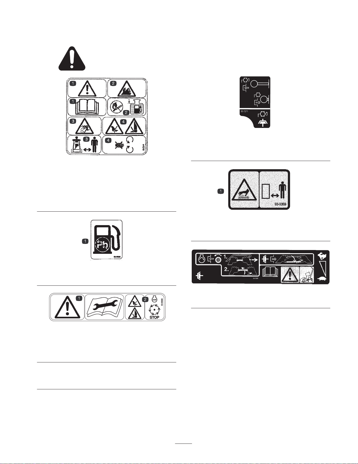
Safety and Instruction Decals
Safety decals and instructions are easily visible to the operator and are located near any
area of potential danger. Replace any decal that is damaged or lost.
Part No. 93-7348
1. Danger—read the operator’s manual.
2. Fire or open flame—sparks, flame, and smoking prohibited. Fill
the fuel tank no higher than to the bottom of the filler neck.
3. Thrown object hazard—keep bystanders away.
4. Cutting hazard to fingers, hands, and feet—do not open or
remove safety shields while engine is running.
Part No. 957271
1. Descriptions to come
Part No. 93-9886
1. Use unleaded fuel only.
Part No. 93-6688
1. Danger—read the
operator’s manual before
performing maintenance.
93-8069
1. Hot surface/burn hazard—stay a safe distance from the hot
surface.
Part No. 957298)
1. Descriptions to come
2. Cutting hazard to hands,
fingers, and feet—stop the
engine before going near
rotating reels.
7
Page 8

General Specifications
Kawasaki, 4-cycle, 3.7 (2.7 kw) air cooled OHV engine, 3600 RPM, 7.57 cu in.
Engine
Fuel capacity 2.64 qt. (2.5 l); regular grade unleaded gasoline
Traction drive
Reel Drive
Reel Clutch Engaging jaw-type, hand operated at transaxle.
Ground speed 2.1 mph (3.4 Km/hr) at 1600 RPM and 4.0 mph (6.4 Km/hr.) at 3100 RPM.
(124 cc) displacement, cast iron cylinder sleeve; electronic ignition with integral
lighting coil; maximum noise suppression muffler; 83 dB(A) at operator ’s ear
“A” section “V” belt on 2.0 P.D. and 3.70 P.D. to countershaft (1. 85:1) 18T and
48T gear) 2.67:1 and 20T and 56T gear (2 . 8:1). All gears 16 pitch, 20_ involute
full depth, 1/2 in. (13 mm) wide. Gears running in oil.
“A” section V-belt on 2.0 P.D. and 3.70 P.D. to countershaft (1. 85:1) 3/8 in. pitch x
3/16 in. wide chain on 20T and 14T sprockets from countershaft. Reduction Engine
to Reel – 1.30:1.
Traction drum
Reduction, Engine to
Traction Drum
Traction Drive Clutch Friction Disk type – Hand operated latch and bail at handle.
Differential Enclosed spur gears
Handle
Traction unit construction Cast aluminum housing.
Reel construction
Width of cut 21 in. (53.3 cm)
Height of cut 1/8 to 11/16 in. (3 to 17 mm).(Optional micro-cut bedknife 1/16” to 11/16”)
Clip frequency 0.197 in. (5.0 mm).
Bedknife/bedbar
Front Rollers
6 in. (15.2 cm) diameter solid rubber on 16 gauge (1.5 mm) steel rims. Two
sections running on ball bearings.
13.86:1
7/8 in. diameter, 17 gauge welded steel tubing with formed steel reinforcement
panel.
Cast aluminum and zinc side plates, aluminum extrusion back plate. Reel unit
independent of traction unit and catcher. 3-1/2 in. (89 mm) diameter 9 blade,
welded tubular construction. Reel blades, high carbon heat treated steel. Reel
bearings, taper roller with adjustment.
Single edge high carbon steel knife, extra hard for long life, screwed to extruded
aluminum one-piece bed bar and back plate.
2 in. (51 mm) O.D. Steel tube with ball bearings, moisture excluding oil seals and
replaceable wear sleeves.
Weight 186 pounds with catcher and cutting unit.
Dimensions
Width 27 in. (0.69 m)
Height 44-3/4 in. (1.1 m)
with handle
Length 60 in. (1.5 m)
including handle and
catcher
8
Page 9

Optional Equipment
Cutting Unit Model No. 04215
Light Kit Model No. 04058
Brush Kit Part No. 2–2949
Skid Kit Part No. 4–7299
Sectional Roller Part No. 4–7319
Urethane Comb Part No. 8–2560
Full Roller Part No. 4–7309
Micro Cut Bedknife Part No. 95–3147
Wiehle Roller (rear cutting unit) Part No. 100–1556
Spark Arrester Kit Part No. 98-3426
Low Cut Bedknife Part No. 88–8990
9
Page 10

Setup
Note: Determine the left and right sides of the machine from the normal operating position.
Loose Parts Chart
Note: Use this chart as a checklist to ensure all parts necessary for assembly have been shipped. If any of these parts are
missing, total setup cannot be completed.
Loose Parts Qty. Where Used
Handle Assembly 1 Install on machine. (Mounting fasteners loosely
installed on mower.)
Throttle stop
Wire retainer
Retainer screw
Retainer nut
Cotter pin
Washer
Spring
Gauge Bar Assembly 1 Use to set height-of-cut.
Machine Screw 10-32 x 0.88 in. (22 mm) 1 Install in gauge bar.
Jam Nut 10-32 1 Install on machine screw.
Grass Basket 1 Install on machine.
EEC Noise Certification 1
Operator’s Manual 1 Read before operating machine.
Operator’s Video 1 View before operating machine.
Engine Operator’s Manual 1
Parts Catalog 1
1
1
Mount throttle wire
1
1
1
1
Mount clutch rod
1
10
Page 11

Installing the Handle
1. Remove handle mounting capscrew, washer and flange
lock nut from main fame (Fig. 1).
2. Secure handle and bell cranks to frame with capscrew,
washer nut previously removed (Fig. 1).
1
3
2
Figure 1
1. Handle
2. Bellcrank–clutch
3. Bellcrank–throttle
3. Raise handle assembly, fit adjusting bar through
slotted hole in handle and latch handle into notch in
adjusting bar (Fig. 2).
2
1
2
3
4
6
5
1
Figure 3
1. Clutch rod
2. Throttle wire
3. Throttle stop
4. Throttle wire retainer
5. Return spring
6. Engine bracket
Adjust Handle Height And
Control Bail
Adjust the height of the handle and travel of the control
bail for operator comfort.
1. To adjust handle height. grasp handle, push down on
adjusting bar with your foot and move handle
assembly up or down until most comfortable position
is achieved (Fig. 2). Lift foot and allow handle to lock
into notch in adjusting handle.
3
Figure 2
1. Adjusting b a r
2. Notches
3. Handle
4. Secure clutch rod to center hole in clutch bell crank
with a flat washer and cotter pin (Fig. 3).
5. Insert throttle wire through small hole in throttle bell
crank and throttle stop (Fig. 3).
6. Secure throttle wire and throttle stop to bell crank with
throttle wire retainer, retainer screw and nut (Fig. 3).
7. Hook return spring into hole in engine bracket and
small hole in clutch bell crank (Fig. 3).
2. To adjust control bail travel, loosen nuts securing
turnbuckle to clutch rod (Fig. 4).
1
2
3
Figure 4
1. Clutch control bail
2. Control rod
3. Turnbuckle
3. Rotate turnbuckle until traction wheels spin, on a
cement floor, when clutch is engaged.
Important Mower should remain stationary when
engine is running and clutch is in the disengaged position.
4. Tighten nuts securing turnbuckle.
11
Page 12

Before Operating
Fill Fuel Tank
Refer to Engine Operator’s Manual for fuel requirements.
Add Engine Oil
Crankcase must be filled with the proper viscosity, grade
and quantity of oil before staring.
Refer to Engine Operator’s Manual for oil requirements.
1. Position mower so the engine is level and clean around
oil level gauge (Fig. 5).
1
Figure 5
1. Oil level gauge
2. Remove gauge by rotating counterclockwise.
3. Wipe gauge clean and insert it into filler port. Then
remove and check level of oil. Do not screw into port.
If level is low, add only enough oil to raise level to
filler opening.
Note: The TORO Company recommends that the oil level
be checked each time mower is used or after every 5
operating hours. Initially, change oil after the first 25
hours of operation; thereafter, change oil after every 50
hours of operation. More frequent oil changes are required
in dusty or dirty conditions.
1. Clean around fuel tank cap and remove cap from tank
(Fig. 6). Fill fuel tank no higher than to bottom of
filter screen. DO NOT OVER FILL.
1
Figure 6
1. Fuel tank cap
2. Install fuel tank cap and wipe up any spilled gasoline.
Danger
Because gasoline is flammable, caution must
be used when storing or handling it. Do not
fill fuel tank while engine is running, hot or
when machine is in an enclosed area. Vapors
may build up and be ignited by a spark or
flame source many feet away. DO NO SMOKE
while filling the fuel tank to prevent the
possibility of an explosion. Always fill fuel
tank outside and wipe up any spilled
gasoline before starting engine. Use a funnel
or spout to prevent spilling gasoline, and fill
tank no higher than to bottom of filter
screen. DO NOT OVER FILL. Store gasoline
in a clean safety approved container and
keep the cap on the container. Keep gasoline
in a cool, well-ventilated place; never in an
enclosed area such as a hot storage shed. To
assure volatility, do not buy more than a 30
day supply of gasoline. Gasoline is a fuel for
internal combustion engines; therefore do
not use it for any other purpose. Since many
children like the smell of gas, keep it out of
their reach because the fumes are explosive
and dangerous to inhale.
12
Page 13

Check Transaxle Oil Level
Adjusting Height-of-cut
Check transaxle oil level before initial startup and after
every 50 hours of operation.
1. Place mower on level surface and remove pipe plug at
rear of gear case. Oil should be to bottom of hole
(Fig. 7).
1
Figure 7
1. Pipe plug
2. If level is correct, replace plug. If level is too low,
remove plug in top cover and add SAE 90 gear oil
(Fig. 8). Replace both plugs.
Effective cutting height is dependent upon the condition
of the turf grass and the selection of various combinations
of skids or rollers available for the Greensmaster 500.
Effective height-of-cut on a green is influenced by the
type of grass, frequency of mowing, amount of thatch and
resilience of the soil — which is affected by the moisture
and organic matter content. The Greensmaster 500
provides an opportunity to select rollers, skids or
bedknives suitable for all types of greens turf grasses. For
example, progressively lower heights-of-cut with the same
gauge setting may be obtained by selecting, in the
following order: the skid, full front roller, sectional roller
or the Wiehle roller. The reason for this is that
progressively less supporting or contact area is provided
for the cutting unit. The micro-cut bedknife provides a
height-of-cut to 1/16, if desired.
1. Loosen nut on gauge bar and set adjusting screw to
obtain desired distance between bottom of screw head
and face of bar (Fig. 9). Tighten nut, making sure
adjustment is not altered.
2
3. To drain transaxle, remove both plugs and tip unit
rearward.
1
Figure 8
1. Transaxle oil fill plug
1
3
Figure 9
1. Gauge bar
2. Height adjustment screw
2. Remove the cutting unit; refer to removal and
Installation of Cutting Unit.
3. Place cutting unit upside down on bench, position
gauge bar on end of unit with one end on front
support: skid, full roller, sectional roller, etc., the other
end on rear roller (Fig. 10).
4. Loosen top nut on adjusting screws on each side plate
(Fig. 10) and turn adjusting nut to raise or lower front
roller or skid assembly (Fig. 10). Adjust to make
contact with outer end of gauge bar. When proper
adjustment is obtained, screw head on gauge bar will
just pass over cutting edge of bedknife (Fig. 10).
ASSURE HEIGHT-OF-CUT IS EXACTLY
IDENTICAL AT BOTH ENDS OF BEDKNIFE.
3. Nut
13
Page 14

1
3
4
2
3
Figure 10
1. Gauge bar against rollers
2. Screw head over cutting
edge
3. Top nut
4. Adjustment nut
5. Tighten top nuts to secure roller adjustment (Fig. 10).
Turn cutting unit over and place on a level surface
(Fig. 11). Press down on each end of the front and rear
rollers (Fig. 11). Each roller should contact level
surface completely across unit (Fig. 11). If rollers do
not contact, repeat steps 3 and 4.
2
1. Nut
2. Reel bracket
2
1
Figure 12
3. Side plate
1
1
Figure 11
1. Level surface 2. Press down
Reel To Bedknife Adjustment
Note: Adjustment procedures can usually be more
accurate and precise with cutting unit adjusted on a
workbench.
1. Loosen nuts securing left and right reel brackets to
side plates (Fig. 12).
2. Adjust reel to knife clearance with adjusting screws at
each end of unit (Fig. 13). NEVER ALLOW
BEDKNIFE TO BEAR HEAVILY AGAINST REEL.
Figure 13
1. Reel adjusting screw
3. Place the newspaper at right angles to the top face of
the bedknife against the front cutting edge and rotate
the reel blades against the paper. The reel blades
should cut the paper cleanly all across the bedknife. If
the paper is not cleanly cut, the mower should be
either backlapped or resharpened: refer to Backlap
Operation and Reel and Bedknife Grinding.
4. Place a strip of newspaper flat on the top face of the
bedknife and adjust reel down until reel blades pinch
the paper equally all across the bedknife.
5. Tighten nuts to secure the adjustment.
14
Page 15

Adjust Rear Roller Scraper
The adjustment of the rear roller scraper depends on the
many conditions of the green (i.e. leaves, seeds, dew,
etc.).
1. Adjust scraper rod locknuts and brackets to attain
.06”–.10” clearance between scraper rod and roller
surface. Distance between bottom of rod and level
surface should be the same height as height-of-cut
setting.
2. Slide sleeves back on each ball joint and rotate each
pull arm upward off the ball studs.
3. Align cutting unit with roller and driveshaft with
transaxle shaft and lengthen or shorten pull rods by
threading ball socket on rod (Fig. 15).
4. Align ball sockets with ball studs so hooded portion of
socket is at top and open side toward stud (Fig. 16).
Figure 16
1
Figure 14
1. Scraper rod 2. Bracket
2. Assure scraper rod is parallel to roller and level
surface.
Note: Readjust height of scraper rod if height-of-cut is
changed.
2
Check Cutting Unit Alignment
The cutting unit must be in alignment with the front yoke
roller so that the machine will track in a straight line
across the greens. The driveshaft must also be aligned
with the transaxle output shaft. If unit is not properly
aligned, use the following alignment procedures.
1. Loosen jam nut securing ball sockets to pull arms on
both side of the yoke (Fig. 15).
5. Slide the sleeve back on the ball joint and rotate the
pull arm down so the socket fits over the ball stud.
Release the sleeve so it slids forward over the stud and
locks the assemblies together. Tighten the jam nuts to
secure the sockets in position (Fig. 16).
Install Grass Catcher
1. Set pins on basket pivots into brackets on yoke and
allow basket adjusting screw to rest onto yoke
(Fig. 17).
2
1
4
3
3
1. Jam nut
2. Ball socket
2
1. Basket pivot
2. Yoke bracket
1
Figure 15
3. Pull arm
2. Measure distance between lip of basket and edge of
cutting unit shield. There should be a clearance
between the components of no more than 1/4 inch
(6 mm) (Fig. 18). If the dimension is incorrect, adjust
basket.
Figure 17
3. Adjusting screw
4. Jam nut
15
Page 16

Note: Basket should be lower in front to assist clipping
throw into basket. Adjust screw to lower basket (Fig. 17).
Make sure basket clears roller by at least 1/16 in.
(1.6 mm).
3. Tighten jam nuts on each side of basket for adjusting
screws (Fig. 17). Be sure dimension is equal on both
sides of unit.
1
Figure 18
1. 1/4 inch (6mm) maximum clearance
16
Page 17

Operation
Controls
Throttle Control Lever
Throttle control lever (Fig. 19) connects to and operates
throttle linkage to carburetor. Control has two positions:
SLOW and FAST. Engine speed can be varied between
the two settings.
2
1
Figure 19
1. Throttle control lever 2. Clutch control bail
Clutch Control Bail
2
1
Figure 20
1. Fuel shut–off valve 2. Choke lever
Engine Stop Switch
Engine stop switch (Fig. 21) is located at front of engine.
Rotate to OFF to stop engine.
Recoil Starter
Pull recoil starter handle (Fig. 21) to start engine.
Clutch control bail (Fig. 19) controls traction and cutting
unit drive. Control has two positions: ENGAGE and
DISENGAGE. Move control to the right before engaging.
Choke Lever
Choke lever (Fig. 20) is located at rear of engine. Lever
has two positions: RUN and CHOKE. Move lever to
CHOKE position when starting a cold engine. After
engine starts move lever to RUN position.
Fuel Shut–off Valve
Fuel shut–off valve (Fig. 20) is located at right side of
engine. Valve has two positions: CLOSED and OPEN.
Move lever to closed position when storing machine.
Open valve before starting engine.
2
1
Figure 21
1. Engine stop switch 2. Recoil starter
17
Page 18

Reel Drive Control
Reel drive control knob (Fig. 22), located at right side
transaxle, has two positions: ENGAGE and DISENGAGE.
Pull out knob to engage reel drive clutch. Push in to
disengage.
1
7. Pull wire off spark plug to prevent possibility of
accidental starting before storing machine.
8. Close fuel valve before storing machine (Fig. 20).
Transport Operation
1. Assure clutch bail is DISENGAGED and start engine.
2. Disengage cutting unit drive (Fig. 22).
Important Excessive operating of the cutting unit with
the absence of any grass clippings (lubricant) can damage
the cutting unit.
3. Place the handle assembly in the uppermost notch on
handle adjusting bar. Set throttle control in SLOW, tip
front of machine up and slowly increase engine speed
while gradually engaging clutch control bail so mower
moved forward slowly.
Figure 22
1. Reel drive control knob—Pull out to Engage
Starting And Stopping
Note: Make sure wire is installed on spark plug.
1. Assure traction clutch control bail (Fig. 19) and reel
drive knob (Fig. 22) are in DISENGAGED position.
2. Open fuel valve at right side of engine (Fig. 20).
3. Turn ON/OFF switch to ON (Fig. 21)
4. Move choke lever (Fig. 20) to CHOKE position before
starting a cold engine, only if necessary.
Note: A warm or hot engine does not require any choking.
To start a warm engine, move throttle control to mid
throttle position.
5. Stand behind the machine, move the throttle control
lever to mid throttle position (Fig. 19). Pull recoil
starter handle out until positive engagement results.
Pull handle to start engine and allow rope to recoil
slowly. Open choke as engine warms up, if used.
Important Do not pull recoil rope to its limit or let go
of starter handle when rope is pulled out because rope
may break or recoil assembly may be damaged.
6. To stop engine during operation, release clutch bail to
DISENGAGE position (Fig. 21), throttle control to
SLOW (Fig. 19) and turn ON/OFF switch to OFF
(Fig. 21).
4. Adjust throttle to operate mower at desired ground
speed and transport mower to desired destination.
Prior To Mowing
Remove all foreign objects from the turf prior to mowing.
Be sure the Greensmaster is carefully adjusted and is set
evenly on both sides of the reel. Improper mower
adjustment is magnified many times over in the
appearance of the clipped turf. Ensure everyone,
especially children and pets, is clear of the work area.
Method Of Mowing
The greens should be mowed in straight back and forth
direction across the green. Avoid circular mowing or
turning the mower on greens areas since scuffing may
occur. Turning the mower should be done off the green
proper by raising the cutting reel (pushing the handle
down) and turning on the large rubber covered traction
drums. Mowing should be done at a normal walking pace.
Faster speed saves very little time and will result in an
inferior mowing job.
Operating Controls
To operate controls for mowing;
1. Start engine, push down on handle to elevate cutting
unit, raise traction clutch bail to handle and transport
machine onto collar of green.
2. Release traction clutch bail (Fig. 23) to DISENGAGE
position and pull reel drive control knob on transaxle
fully out to ENGAGE reel (Fig. 24).
18
Page 19

After Mowing
1
Figure 23
1. Traction clutch contro l b a i l
1
1. Drive off green, release clutch control bail to
DISENGAGE, stop the engine and push the reel drive
control knob full in to DISENGAGE.
2. Empty the grass catcher of clippings, install grass
catcher and commence transport operation; refer to
Transport Operation.
3. Chock wheels if mower is left unattended on an
incline.
Figure 24
1. Reel drive control knob—Pull out to Engage
3. Raise the clutch control bail to handle, increase
throttle speed until the unit is traveling at the desired
ground speed, drive the mower out onto the green area,
drop the front of the mower down and commence
mowing operation.
19
Page 20

Lubrication
Grease Fittings
The grease fittings on the mower should be greased at
least every 25 hours. Lubricate using a No. 2
multi–purpose lithium base grease. A hand operated
grease gun is recommended for best results.
1. Wipe each grease fitting with a clean rag.
2. Grease components as follows:
• Cutting unit reel bearings, drive shaft bearing, front
roller or support, yoke pivot and pull arm bushings and
rear cutting unit and yoke rollers (Fig. 25).
2
1
1
1
Figure 25
1. Pipe plug
• To lubricate the rear cutting unit and yoke rollers,
remove pipe plugs at each end, install 1/8-27 NPT
grease fittings, lubricate bearings, remove fittings and
replace pipe plugs (Fig. 25). Apply grease to enclosed
bearing areas only until pressure is felt against the
grease gun.
• Front roller or support, yoke pivot and pull arms; apply
grease to bearings until it begins to show (Fig. 25).
Figure 26
1. Clutch assembly 2. Clutch friction discs
Linkage Pivot Points
Oil all pivot points of control linkages weekly with SAE
30 engine oil (Fig. 27, 28).
Figure 27
Important Do not apply too much pressure or grease
seals will be permanently damaged.
3. Wipe excess grease away.
Greasing Traction Clutch
1. At the end of each seasons cutting, remove the traction
clutch assembly and clean and re–pack the cam and
roller assembly with No. 5 multi–purpose (wheel)
bearing grease (Fig. 26). Take extreme care to make
sure that grease is kept off the clutch friction discs
(Fig. 26).
Figure 28
20
Page 21

Maintenance
Note: Determine the left and right sides of the machine from the normal operating position.
Recommended Maintenance Schedule
Maintenance Service
Interval
After first 10 hours • Adjust traction belt drive
After first 25 hours
Every 25 hours
Every 50 hours
Every 100 hours
Every 200 hours
Annually • Adjust reel drive chain
Maintenance Procedure
• Change the engine oil.
• Clean the fuel filter.
• Service the air filter pre-cleaner.
• Check for loose fasteners.
• Lubricate all grease fittings
• Clean the fuel filter and sediment bowl.
• Change the engine oil.
• Check the transmission fluid level.
• Adjust traction belt drive
• Check the cut-off bar adjustment.
• Service the air cleaner filter.
• Clean the combustion chamber.
• Replace the spark plug.
• Adjust the valves and torque the head bolts.
• Service the air cleaner filter.
Important Refer to your engine operator’s manual for additional maintenance procedures.
21
Page 22

Daily Maintenance Checklist
Duplicate this page for routine use.
For the week of:
Maintenance Check Item
Check that pivot joints operate freely.
Check the fuel level.
Check the engine oil level.
Check the air filter.
Clean the engine cooling fins.
Check for unusual engine noises.
Check for unusual operating noises.
Check the reel-to-bedknife adjustment.
Check the height-of-cut adjustment.
Touch up damaged paint.
Notation for Areas of Concern
Inspection performed by:
Item Date Information
1
2
3
Mon. Tues. Wed. Thurs. Fri. Sat. Sun.
4
5
6
7
8
22
Page 23

Removal And Installation Of
Cutting Unit
To remove the cutting unit:
2. Install the chains onto the support hooks (Fig. 29).
3. Align pull arms with ball studs, slide sleeves back on
sockets, and drop arm sockets down on ball studs
(Fig. 30).
1. Remove grass catcher and unhook the two chains from
the support hooks (Fig. 29).
2
1
3
Figure 29
1. Chains
2. Support hooks
2. Slide sleeves back on pull arm ball joints and lift pull
arm sockets straight up off ball studs (Fig. 30).
3. Cotter pin
4. Yoke pivot
4
2
1
4. Make sure the cutting unit is aligned with the yoke
roller and the drive shaft with the transaxle shaft. If
there is misalignment, refer to Check Cutting Unit
Alignment.
Removing Yoke Assembly
To remove yoke:
1. Remove grass catcher and unhook chains from support
hooks (Fig. 29).
2. Remove cotter pin from yoke pivot and slide yoke
assembly off pivot (Fig. 29).
3. Reverse procedure to install yoke.
Engine Care
The Engine Manual supplied with your Greensmaster 500
provides the maintenance procedures for service of the air
cleaner, oil requirements, ignition components, etc.
Changing Engine Oil
1. Start and run engine to warm the engine oil.
3
1
Figure 30
1. Sleeve
2. Pull arm socket
3. Grasp cutting unit chain case and pull cutting unit and
drive shaft out to right, away from traction unit.
Note: Right and left sides are determined by standing in
the operator’s position.
To install the cutting unit:
1. Slide the cutting unit under the yoke from the right
side, line the drive shaft up with the transaxle shaft,
and install the drive shaft.
2
3. Ball stud
2. Stop engine, place a drain pan under plug in crankcase
on handle side of engine, remove oil drain plug and
allow oil to drain into drain pan (Fig. 31).
1
2
3
Figure 31
1. Oil fill plug
2. Handle
3. Oil drain plug
23
Page 24

3. Install drain plug; remove oil fill plug (Fig. 31), assure
engine is level and fill crankcase with fresh clean oil;
refer to Engine Operator’s Manual for oil
requirements.
2. Traction wheels will spin, on a cement floor, when
clutch is engaged.
Traction Drive Belt Adjustment
The belt should be tight enough so traction wheels will
spin on cement floor when clutch is engaged with the
engine running. Belt should be checked after first 10 hours
of operation and tightened if necessary. To adjust the belt:
1. Remove belt cover from left side of machine (Fig. 32).
2
1
Figure 32
1. Cover 2. Engine mounting fastener
2
1
Figure 33
1. Locknut 2. Clutch friction discs
3. Repeat adjustment until clutch operates correctly.
Important Mower should remain stationary when
engine is running and clutch is in the disengaged position.
Note: Clutch plates and friction discs should be totally
free of grease or oil (Fig. 33).
Cutting Unit Chain Adjustment
2. Loosen the four engine hold down screws.
3. Slide engine rearward equally on both sides until belt
is tight. Tighten mounting fasteners and check
adjustment by placing unit on a cement floor, starting
engine and checking to see if traction wheels spin
when clutch is engaged.
4. Continue adjustment until tension is correct and install
belt guard (Fig. 32).
Clutch Adjustment
Should clutch slip during operation, check and adjust as
follows:
Warning
Do not adjust clutch with the engine running.
Clutch could catch and cause harm to both
you and machine.
1. Tighten clutch locknut in small increments, start
engine and test adjustment (Fig. 33).
Once each year, check the chain assembly inside the
cutting unit chain case. Use the following procedures:
1. Remove the grass catcher and cutting unit from the
traction unit; refer to Removal and Installation of
Cutting Unit.
2. Remove Allen head set screw anchoring steel shaft to
cover (Fig. 34).
1
2
3
Figure 34
1. Chain case
2. Allen head set screw
3. T apered nuts
24
Page 25

3. Remove (5) cover screws and (2) tapered nuts and
remove cover (Fig. 34).
4. Check chain for excess slack (Fig. 35). If chain is too
slack, loosen mounting screw for chain idler shoe,
push down against chain to remove slack and tighten
screw (Fig. 35).
1
3
3
2
1
2
Figure 35
1. Chain
2. Idler screw
3. Shoe
5. Make sure a liberal quantity of lithium base No.2
grease is around sprocket and install cover (Fig. 35).
Install tapered nuts first to make sure cover is aligned
with the case (Fig. 35).
6. If idler shoe is worn excessively, flip and use other
side or replace.
Reel Bearing Adjustment
Loose reel bearings will affect cutting performance. Do
not forget to make a check of the bearing adjustment as a
part of your troubleshooting procedures if your cutting
unit performance has deteriorated. Also check and adjust
the reel bearings before doing any reel grinding.
2
5
4
1
3
Figure 36
1. Locknut
2. Reel adjust screw
3. Allen head screw
4. Capscrew
5. Left reel bracket
3. Check the bearing preload either by use of a torque
wrench by the following method:
• Install a 1/4-20 screw into hole in end of reel shaft
(Fig. 37).
• Support the reel and hang a 5 lb. (2.27 Kg) weight 1
in. (25 mm) away from center of reel shaft and 10 in.
(25 cm) down (Fig. 37).
• Weight should be just held when screw is
perpendicular to center line of reel shaft.
1. Remove grass catcher and cutting unit from traction
unit; refer to Removal and Installation of Cutting Unit.
2. Remove locknut, reel adjustment screw, Allen head set
screw, and capscrew from left reel bracket. Remove
reel bracket from left side plate (Fig. 36).
Figure 37
25
Page 26

4. If torque wrench is used, there should be 5–10 in-lb
(5.6–11.3 Nm) drag on reel shaft. Rotate the shaft and
repeat check to be sure bearings are aligned in cup and
cone.
5. If bearings need adjustment, locate and remove lock
tab from lockwasher inserted into slot on locknut
(Fig. 38).
4. Use a good grade of medium grit (80) commercial
lapping compound with a water soluble carrier to
assure the compound will be easily washed away at the
completion of the backlapping operation. Dry lapping
compound should be mixed with liquid detergent
(soap) until the material is of free flowing consistency.
Note: Paste-type pre–mixed lapping compound is also
sold in some areas. This is generally used in its original
composition and therefore is not free flowing.
2
1
Figure 38
1. Locknut 2. Lockwasher
6. Adjust locknut in small increments and check for
proper preload. Bend ears of lockwasher into slots on
locknut when adjustment is completed to secure
locknut (Fig. 38).
Important Do not over–adjust or bearing life will be
affected.
7. Install left reel bracket.
Backlap Operation
5. Operate the lapping machine so the reel turns in a
reverse direction for about three minutes. apply
lapping solution continuously with a paint brush across
the full width of the reel.
Caution
Be careful when lapping the reel because
contact with the reel or other moving parts
can result in personal injury.
6. Again, lightly adjust the bedknife and reel. Then, lap
for approximately two additional minutes. Apply
lapping solution continuously.
7. Wash off all lapping solution.
8. Using newspaper, check for sharpness along the entire
length of each reel blade. If the newspaper cannot be
cut cleanly along the entire length of each blade,
grinding or re–grinding is necessary; refer to Reel and
Bedknife Grinding.
Note: For a better cutting edge, run a file across the front
face of the bedknife when the lapping operation is
completed. This will remove any burr or rough edge that
may have built up on the cutting edge.
Backlap when reel blades and bedknife edge are slightly
rounded and do not cut the grass cleanly with a light reel
to bedknife adjustment. Also backlap after a reel and
bedknife have been reground to establish a land area and
assure a perfect match between reel and bedknife cutting
edge. Backlapping will not correct nicked or severely
rounded reel blades or uneven bedknife wear. Correct
these conditions by repairing, replacing or re–grinding the
components.
1. Using a fine–tooth file, remove high spots from reel
blades. If any blade is bent, straighten by placing a
hammer on one side of blade and tapping on opposite
side.
2. Adjust the reel to bedknife to obtain a light contact;
refer to Reel to Bedknife Adjustment.
3. Connect a lapping machine to the cutting unit with an
extension coupler, and socket.
Reel And Bedknife Grinding
Refer to the TORO GUIDE TO REEL AND ROTARY
MOWER SHARPENING. Copies are available from your
local Toro distributor.
Note: In order to grind the bedknife, it has to be removed
from the cutting unit. The bedknife is then mounted on the
grinding bar (TOR 31397).
Cleaning Mower
It is recommended to wash the cutting unit, transaxle, and
grass basket after each day’s use. Chemicals in the turf
may cause premature deterioration to certain components
if not washed daily.
Important Do not direct “high–pressure” water at oil
seals, bearings, electrical connectors/switches, hot engine,
etc.; contamination of these parts could cause premature
wear.
26
Page 27

Electrical Schematic
INTEGRAL
LIGHTING
COIL
SPARK PLUG
COMBINATION
IGNITOR/IGNITION
COIL
SWITCH
ENGINE IGNITION,
OPEN TO RUN
Storage
• Drain gasoline from fuel tank. Start engine and let it
run at slow speed until it stops because all gasoline is
used.
• Drain oil from crankcase: refer to Engine Operator’s
Manual. However, do not fill crankcase with oil at this
time.
• Remove grass clippings, dirt and grime from external
parts of mower housing and engine. Also clean the
engine cooling system.
• Clean carbon from internal parts of engine and
re–assemble engine.
• Pull wire off spark plug and clean area around plug so
foreign matter cannot fall into cylinder when plug is
removed. Remove plug from cylinder head and pour
two tablespoons (25 ml) of engine oil into spark plug
hole. Pull recoil starter handle slowly to distribute oil
on inside of cylinder. Reinstall spark plug. If torque
wrench is not used, tighten plug firmly. DO NOT
INSTALL WIRE ON SPARK PLUG.
• Remove the belt cover over left side of machine.
Inspect the belt for excessive wear or damage. Repair
or replace as necessary. Assure belt is in disengaged
position.
• Check condition of reel blades and bedknife: repair
and sharpen as necessary; refer to Reel And Bedknife
Grinding.
• Lubricate mower: refer to Lubrication.
• Clean the air cleaner.
• Check and tighten all capscrews, screws, bolts, nuts
and mating parts. If any part is damaged, repair or
replace it.
• “Touch up” all rusted or chipped paint surfaces. Make
sure to sand affected area before painting.
Note: TORO Re–Kote “touch–up” paint is available from
an Authorized Toro Service Dealer or Distributor. The
spray paint dries in minutes to a glossy, factory–finish.
• Fill crankcase with oil: refer to Engine Operator’s
Manual.
• Store the mower in a clean, dry place. Cover the
mower to protect it and keep it clean.
27
Page 28

The Toro General Commercial Products Warranty
A Two-Year Limited Warranty
Conditions and Products Covered
The Toro Company and its affiliate, Toro Warranty Company,
pursuant to an a g r eement between them, jointly warrant your Toro
Commercial Product (“Product”) to be free from defects in
materials or workmanship for two years or 1500 operational
hours*, whichever occurs first. Where a warrantable condition
exists, we will repair the Product at no cost to you including
diagnosis, labor, parts, and transportation. This warranty begins
on the date the Product is delivered to the original retail purchaser.
* Product equipped with hour meter
Instructions for Obtaining Warranty Service
You are responsible for notifying the Commercial Products
Distributor or Authorized Commercial Products Dealer from whom
you purchased the Product as soon as you believe a warrantable
condition exists.
If you need help locating a Commercial Products Distributor or
Authorized Dealer, or if you have questions regarding your
warranty rights or responsibilities, you may contact us at:
Toro Commercial Products Service Department
Toro Warranty Company
8111 Lyndale Avenue South
Bloomington, MN 55420-1196
952-888-8801 or 800-982-2740
E-mail: commercial.service@toro.com
Owner Responsibilities
As the Product owner, you are responsible for required maintenance and adjustments stated in your operator’s manual. Failure
to perform required maintenance and adjustments can be grounds
for disallowing a warranty claim.
Items and Conditions Not Covered
Not all product failures or malfunctions that occur during the
warranty period are defects in materials or workmanship. This
express warranty does not cover the following:
• Product failures which result from the use of non-Toro
replacement parts, or from installation and use of add-on,
modified, or unapproved accessories
• Product failures which result from failure to perform required
maintenance and/or adjustments
• Product failures which result from operating the Product in an
abusive, negligent or reckless manner
• Parts subject to consumption through use unless found to be
defective. Examples of parts which are consumed, or used up,
during normal Product operation include, but are not limited to,
blades, reels, bedknives, tines, spark plugs, castor wheels,
tires, filters, belts, and certain sprayer components such as
diaphragms, nozzles, and check valves, etc.
• Failures caused by outside influence. Items considered to be
outside influence include, but are not limited to, weather,
storage practices, contamination, use of unapproved coolants,
lubricants, additives, or chemicals, etc.
• Normal “wear and tear” items. Normal “wear and tear” includes,
but is not limited to, damage to seats due to wear or abrasion,
worn painted surfaces, scratched decals or windows, etc.
Parts
Parts scheduled for replacement as required maintenance are
warranted for the period of time up to the scheduled replacement
time for that part.
Parts replaced under this warranty become the property of Toro.
T oro will make the final decision whether to repair any existing part
or assembly or replace it. Toro may use factory remanufactured
parts rather than new parts for some warranty repairs.
General Conditions
Repair by an Authorized Toro Distributor or Dealer is your sole
remedy under this warranty.
Neither The Toro Company nor Toro Warranty Company is
liable for indirect, incidental or consequential damages in
connection with t h e use of the T oro Products covered by this
warranty, including any cost or expense of providing substitute equipment or service during reasonable periods of
malfunction or non-use pending completion of repairs under
this warranty. Except for the Emissions warranty referenced
below, if applicable, there is no other express warranty. All
implied warranties of merchantability and fitness for use are
limited to the duration of this express warranty.
Some states do not allow exclusions of incidental or consequential
damages, or limitations on how long an implied warranty lasts, so
the above exclusions and limitations may not apply to you.
This warranty gives you specific legal rights, and you may also
have other rights which vary from state to state.
Note regarding engine warranty: The Emissions Control System
on your Product may be covered by a separate warranty meeting
requirements established by the U.S. Environmental Protection
Agency (EPA) and/or the California Air Resources Board (CARB).
The hour limitations set forth above do not apply to the Emissions
Control System Warranty. Refer to the Engine Emission Control
Warranty Statement printed in your operator’s manual or contained in the engine manufacturer’s documentation for details.
Countries Other than the United States or Canada
Customers who have purchased Toro products exported from the United States or Canada should contact their T oro Distributor (Dealer)
to obtain guarantee policies for your country, province, or state. If for any reason you are dissatisfied with your Distributor’s service or
have difficulty obtaining guarantee information, contact the Toro importer. If all other remedies fail, you may contact us at Toro Warranty
Company.
Part No. 374-0031 Rev. C
 Loading...