

Page 1
FormNo.3360-173RevA
LightKit
2008andlaterGreensmaster
ModelNo.04061
Beforeservicingormakingadjustmentstothemachine,stopengineandremovethewirefromthe
sparkplug.
®
WalkBehingMowers
InstallationInstructions
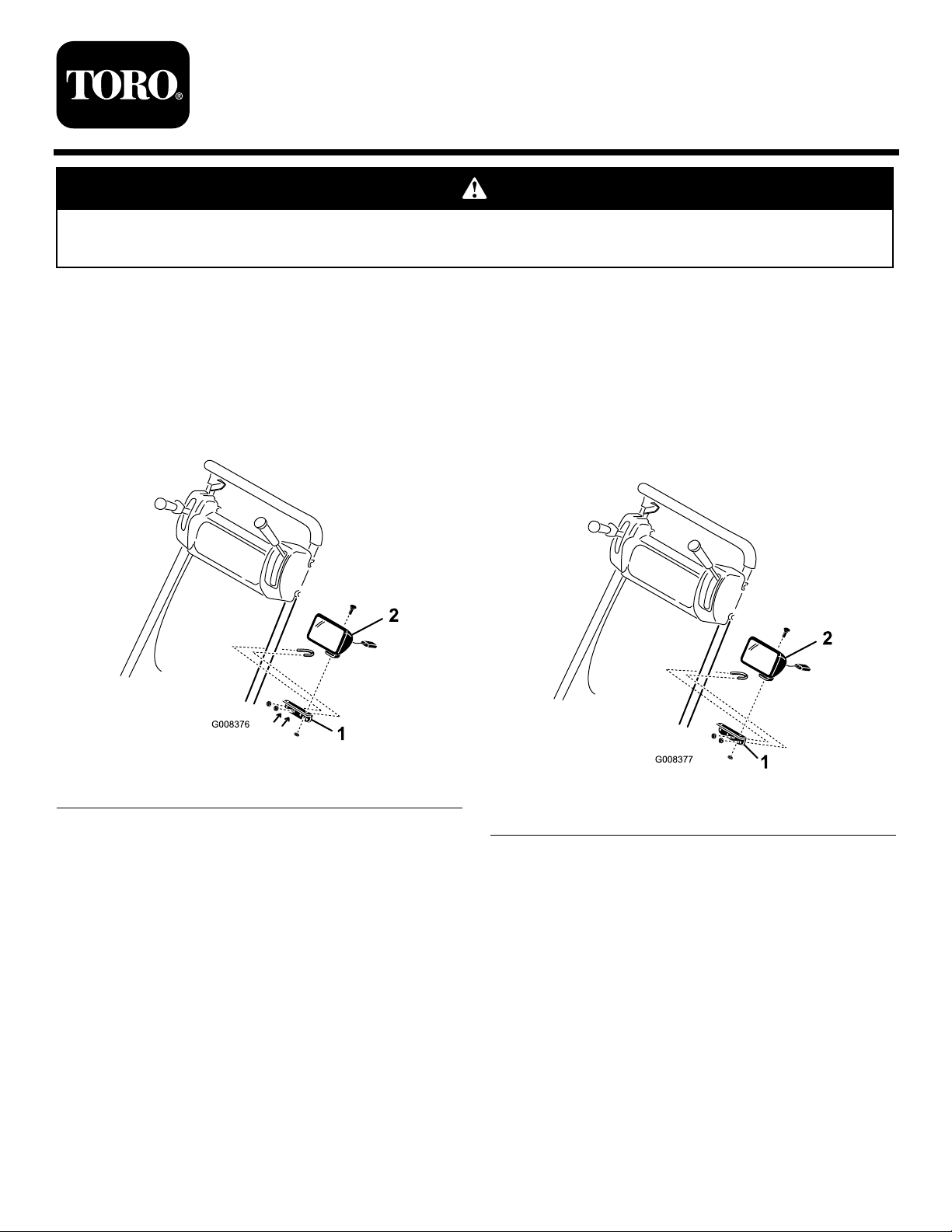
InstallingtheLights
ForGreensmasterFlex18
1.Aligntheinnersetoflightbracketmountingholes
withthehandle.Thelightbracketshouldextend
outwardfromthehandle(Figure1).
Figure1
1.Lightbracket2.Light
2.Looselysecurethelightbrackettothehandlewitha
clampandtwonyloninsertlocknuts(Figure1).
3.Positionthelightbracketapproximately6"below
theconsole.
4.Tightenthetwonyloninsertlocknuts(Figure1).
ForGreensmasterFlex21,
Greensmaster1000,Greensmaster
1600,Greensmaster2000and
Greensmaster2600
1.Aligntheoutersetoflightbracketmountingholes
withthehandle.Thelightbracketshouldextend
inwardfromthehandle(Figure2).
Figure2
1.Lightbracket2.Light
2.Looselysecurethelightbrackettothehandlewitha
clampandtwonyloninsertlocknuts(Figure2).
3.Positionthelightbracketapproximately6"below
theconsole.
5.Usingtheoutermountingholeinthelightbracket,
mountthelighttothebracketwithacarriagebolt,
lockwasherandnut(Figure1).
©2008—TheToro®Company
8111LyndaleAvenueSouth
Bloomington,MN55420
Registeratwww.Toro.com.
4.Tightenthetwonyloninsertlocknuts(Figure2).
5.Usingtheoutermountingholeinthelightbracket,
mountthelighttothebracketwithacarriagebolt,
lockwasherandnut(Figure2).
OriginalInstructions(EN)
PrintedintheUSA.
AllRightsReserved
Page 2
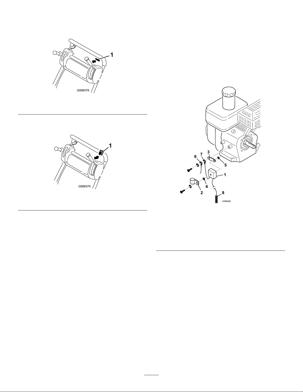
ConnectingtheLights
1.Removetheplugfromtheholeinthetopofthe
console(Figure3).
Figure3
1.Plug
2.InserttheON/OFFtoggleswitchintotheconsole
hole(Figure4).
5.Mountthevoltageregulatorstrap,voltageregulator
groundwireringterminalandtheharnessground
wireringterminaltotheenginebosswithaexternal
toothlockwasherandcapscrew(Figure5).Usethe
righthandboss.
6.Feedtheenginewiresandthevoltageregulatorwires
throughtheR-clamp(Figure5).
7.Securethewireharnesstothehandleusingthenylon
cableties.Checkallthewiresforexcessbending,
chafngorinterferencewithmountingparts.
Figure4
1.Toggleswitch
3.Connectthewireharnessasfollows:
A.Plugthelargewireharnessconnectorintothe
lefthandlelight.
B.Routetheharnessalongthebottomofthe
consolepanel.
C.Plugthewireconnectorintotheterminalonthe
toggleswitch.
D.Connectthedoublewireleadtothecenter
terminalonthetoggleswitch.
E.Plugthenextwireharnessconnectorintothe
righthandlelight.
F.Routetheharnessdowntherighthandletothe
rearoftheengine.
G.Plugthetwoharnessconnectorsintotheyellow
leadscomingfromengine.
H.Plugthevoltageregulatorconnectorintothe
wireharnessconnector.
4.Mountthevoltageregulator,voltageregulatorstrap,
washersandR-clamptothecapscrewwithajamnut
andlocknut(Figure5).
Figure5
1.Voltageregulator5.Locknut
2.R-clamp6.Harnessgroundwire
3.Voltageregulatorstrap7.Regulatorgroundwire
4.Jamnut8.Voltageregulator
connectortowireharness
connector
8.Adjustthelightsasfollows:
A.Removethetransporttiresandrestthemower
onthedrum.
B.Makesurethegrassbasketisinstalledonthe
mower.
Note:Donotpositionthemoweronthe
kickstand.
C.Loosenthefastenerssecuringthelightassemblies
tothemountingbrackets
D.Starttheengine.
E.Turnonthelights.
F.Adjustthelightstothedesiredposition.
G.Tightenthemountingfasteners.
2
 Loading...