

Toro 04055, 04056, Greensmaster 800, Greensmaster 1000, Greensmaster 1600 Operator's Manual
Page 1

FormNo.3389-568RevA
Greensmaster
®
800,1000,or
1600Mower
ModelNo.04054—SerialNo.314004001andUp
ModelNo.04055—SerialNo.314004001andUp
ModelNo.04056—SerialNo.314004001andUp
Registeratwww.T oro.com.
OriginalInstructions(EN)
*3389-568*A
Page 2
ThisproductcomplieswithallrelevantEuropeandirectives;
fordetails,pleaseseetheseparateproduct-specic
DeclarationofConformity(DOC)sheet.
WARNING
CALIFORNIA
Proposition65Warning
Thisproductcontainsachemicalorchemicals
knowntotheStateofCaliforniatocausecancer,
birthdefects,orreproductiveharm.
Theengineexhaustfromthisproduct
containschemicalsknowntotheStateof
Californiatocausecancer,birthdefects,
orotherreproductiveharm.
ThissparkignitionsystemcomplieswithCanadianICES-002.
Becauseinsomeareastherearelocal,state,orfederal
regulationsrequiringthatasparkarresterbeusedonthe
engineofthismachine,asparkarresterisincorporatedwith
themuferassembly.
GenuineT orosparkarrestersareapprovedbytheUSDA
ForestryService.
Important:Thisengineisequippedwithaspark
arrestermufer.ItisaviolationofCaliforniaPublic
ResourceCodeSection4442touseoroperatetheengine
onanyforest-covered,brush-covered,orgrass-covered
landwithoutasparkarrestermufermaintainedin
workingorder,ortheengineconstricted,equipped,and
maintainedforthepreventionofre.Otherstatesor
federalareasmayhavesimilarlaws.
CustomerServiceandhavethemodelandserialnumbers
ofyourproductready .Themodelandserialnumbersare
locatedonaplateontherearframe.Writethenumbersin
thespaceprovided.
ModelNo.
SerialNo.
Thismanualidentiespotentialhazardsandhassafety
messagesidentiedbythesafetyalertsymbol(Figure1),
whichsignalsahazardthatmaycauseseriousinjuryordeath
ifyoudonotfollowtherecommendedprecautions.
Figure1
1.Safetyalertsymbol
Thismanualuses2wordstohighlightinformation.
Importantcallsattentiontospecialmechanicalinformation
andNoteemphasizesgeneralinformationworthyofspecial
attention.
Introduction
Thismachineisawalkbehind,reel-bladelawnmower
intendedtobeusedbyprofessional,hiredoperatorsin
commercialapplications.Itisprimarilydesignedforcutting
grassonwell-maintainedlawnsinparks,golfcourses,sports
elds,andoncommercialgrounds.Itisnotdesignedfor
cuttingbrush,mowinggrassandothergrowthalongside
highways,orforagriculturaluses.
Readthisinformationcarefullytolearnhowtooperateand
maintainyourproductproperlyandtoavoidinjuryand
productdamage.Youareresponsibleforoperatingthe
productproperlyandsafely.
YoumaycontactTorodirectlyatwww .Toro.comforproduct
andaccessoryinformation,helpndingadealer,ortoregister
yourproduct.
Wheneveryouneedservice,genuineT oroparts,oradditional
information,contactanAuthorizedServiceDealerorToro
©2014—TheToro®Company
8111LyndaleAvenueSouth
Bloomington,MN55420
Contactusatwww.Toro.com.
2
PrintedintheUSA
AllRightsReserved
Page 3

Contents
Safety...........................................................................4
SafeOperatingPractices...........................................4
ToroMowerSafety..................................................6
Model04054...........................................................6
Model04055...........................................................6
Model04056...........................................................7
SafetyandInstructionalDecals.................................8
Setup...........................................................................10
1InstallingandAdjustingtheHandle........................11
2InstallingtheKickstand(Models04054and
04056)...............................................................12
3InstallingtheTransportWheelShafts(Models
04055and04056)................................................12
4InstallingtheTransportWheels(Optional)..............13
5AdjustingtheCuttingUnit....................................13
6InstallingtheGrassBasket....................................13
ProductOverview.........................................................14
Controls...............................................................14
Specications........................................................16
Attachments/Accessories........................................16
Operation....................................................................17
ThinkSafetyFirst...................................................17
CheckingtheEngine-oilLevel..................................17
FillingtheFuelTank...............................................17
Breaking-intheMachine..........................................18
CheckingtheInterlockSwitchOperation...................18
StartingandStoppingtheEngine..............................19
TransportingtheMachine........................................19
PreparingtoMow...................................................19
Mowing................................................................19
OperatingTips......................................................20
Maintenance.................................................................21
RecommendedMaintenanceSchedule(s)......................21
DailyMaintenanceChecklist....................................22
Lubrication...............................................................23
GreasingtheMachine.............................................23
EngineMaintenance..................................................24
ServicingtheEngineOil..........................................24
ServicingtheAirCleaner.........................................25
ReplacingtheSparkPlug.........................................26
FuelSystemMaintenance...........................................26
CleaningtheFuelFilter...........................................26
ElectricalSystemMaintenance....................................27
ServicingtheInterlockSwitch.................................27
BrakeMaintenance....................................................27
AdjustingtheService/ParkingBrake.........................27
BeltMaintenance......................................................29
AdjustingtheBelts.................................................29
ReplacingtheDifferentialBelt..................................31
ControlsSystemMaintenance.....................................32
AdjustingtheTractionControl.................................32
CuttingUnitMaintenance...........................................32
LevelingtheRearDrumtotheReel...........................32
AdjustingtheBedknifetotheReel............................33
AdjustingtheHeightofCut.....................................34
AdjustingtheGrassShieldHeight.............................35
AdjustingtheCut-offBar........................................35
BedbarIdentication..............................................35
SettingtheMachinetoMatchTurfConditions............36
ServicingtheBedbar...............................................37
BacklappingtheReel...............................................38
Storage........................................................................38
3
Page 4

Safety
–Fuelthemachineoutdoorsonlyanddonotsmoke
whilefuelling.
ThismachinemeetsorexceedsCENstandardEN836:1997,
ISOstandard5395:1990,andANSIB71.4-2012specications
ineffectatthetimeofproductionwhentheOperator
PresenceKit,Part112-9282isinstalled.
Improperlyusingormaintainingthemachinecanresult
ininjury.Toreducethepotentialforinjury,complywith
thesesafetyinstructionsandalwayspayattentiontothe
safetyalertsymbol,whichmeansCaution,Warning,or
Danger—personalsafetyinstruction.Failuretocomplywith
theinstructionmayresultinpersonalinjuryordeath.
SafeOperatingPractices
ThefollowinginstructionsareadaptedfromtheCEN
standardENISO5395:2013andANSIB71.4-2012.
Whenoperatingthismachinebetween5000to8000feet
abovesealevelyouwillneedtoobtainthehigh-altitude
kit.SeeyourAuthorizedToroDealer.
Training
•ReadtheOperator'sManualandothertrainingmaterial
carefully.Befamiliarwiththecontrols,safetysigns,and
theproperuseoftheequipment.
•Iftheoperatorormechaniccannotreadthelanguageof
theOperator'sManualitistheowner’ sresponsibilityto
explainthismaterialtothem.
•Neverallowchildrenorpeopleunfamiliarwiththese
instructionstouseorservicethemachine.Local
regulationsmayrestricttheageoftheoperator.
•Nevermowwhilepeople,especiallychildren,orpetsare
nearby.
•Theowner/usercanpreventandisresponsiblefor
accidentsorinjuriesoccurringtopeople,ordamageto
property.
•Alloperatorsormechanicsmustbetrained.Itisthe
owner’sresponsibilityfortrainingusers.
Preparation
•Whilemowing,alwayswearsubstantialfootwear,long
trousers,hardhat,safetyglasses,andhearingprotection.
Longhair,looseclothing,orjewelrymaygettangled
inmovingparts.Donotoperatetheequipmentwhen
barefootorwearingopensandals.
•Thoroughlyinspecttheareawheretheequipmentisto
beusedandremoveallobjectswhichmaybethrownby
themachine.
•Warning—Fuelishighlyammable.Takethefollowing
precautions:
–Storefuelincontainersspecicallydesignedforthis
purpose.
–Addfuelbeforestartingtheengine.Neverremove
thecapofthefueltankoraddfuelwhiletheengineis
runningorwhentheengineishot.
–Iffuelisspilled,donotattempttostarttheengine
butmovethemachineawayfromtheareaofspillage
andavoidcreatinganysourceofignitionuntilfuel
vaporshavedissipated.
–Secureallfueltanksandcontainercaps.
•Replacedamagedorwornsilencers.
•Evaluatetheterraintodeterminewhataccessoriesand
attachmentsareneededtoproperlyandsafelyperform
thejob.Onlyuseaccessoriesandattachmentsapproved
bythemanufacturer.
•Checkthattheoperator'spresencecontrols,safety
switches,andshieldsareattachedandfunctioning
properly.Donotoperatethemachineunlesstheyare
functioningproperly.
Operation
•Donotoperatetheengineinaconnedspacewhere
dangerouscarbonmonoxidefumescancollect.
•Mowonlyindaylightoringoodarticiallight.
•Beforeattemptingtostarttheengine,disengageallblade
attachmentclutches,shiftintoneutral,andengagethe
parkingbrake.
•Stayalertforholesintheterrainandotherhiddenhazards.
•Watchoutfortrafcwhencrossingornearroadways.
•Stopthebladesrotatingbeforecrossingsurfacesother
thangrass.
•Whenusinganyattachments,neverdirectthedischarge
ofmaterialtowardbystandersnorallowanyonenearthe
machinewhileitisinoperation.
•Neveroperatethemachinewithdamagedguards,shields,
orwithoutsafetyprotectivedevicesinplace.Besure
thatallinterlocksareattached,adjustedproperly ,and
functioningproperly.
•Donotchangetheenginegovernorsettingsoroverspeed
theengine.Operatingtheengineatexcessivespeedmay
increasethehazardofpersonalinjury.
4
Page 5

•Beforeleavingtheoperator'sposition:
–stoponlevelground;
–disengagethecuttingunitandtractiondrive;
–settheparkingbrake;
–stoptheengine.
•Disengagedrivetoattachmentswhentransportingornot
inuse.
•Stoptheengineanddisengagedrivetoattachment:
–beforefuelling;
–beforeremovingthegrasscatcher;
–beforemakingheightadjustments;
–beforeclearingblockages;
–beforechecking,cleaning,orworkingonthemachine;
–afterstrikingaforeignobjectorifanabnormal
vibrationoccurs.Inspectthemachinefordamage
andmakerepairsbeforestartingagainandoperating
theequipment.
•Reducethethrottlesettingbeforestoppingengineand,if
theengineisprovidedwithafuelshut-offvalve,turnthe
valveoffattheconclusionofmowing.
•Keephandsandfeetawayfromthecuttingunit.
•Slowdownandusecautionwhenmakingturnsand
crossingroadsandsidewalks.Stopthereelifyouarenot
mowing.
•Donotoperatethemachineundertheinuenceof
alcoholordrugs.
•Lightningcancausesevereinjuryordeath.Ifyousee
lightningorhearthunderinthearea,donotoperatethe
machine;seekshelter.
•Usecarewhenloadingorunloadingthemachineintoor
outofatraileroratruck.
•Usecarewhenapproachingblindcorners,shrubs,trees,
orotherobjectsthatmayobscurevision.
SafeHandlingofFuels
•Toavoidpersonalinjuryorpropertydamage,use
extremecareinhandlinggasoline.Gasolineisextremely
ammableandthevaporsareexplosive.
•Extinguishallcigarettes,cigars,pipes,andothersources
ofignition.
•Useonlyanapprovedfuelcontainer.
•Neverremovefuelcaporaddfuelwiththeengine
running.
•Allowenginetocoolbeforerefueling.
•Neverrefuelthemachineindoors.
•Neverstorethemachineorfuelcontainerwherethereis
anopename,spark,orpilotlightsuchasonawater
heateroronotherappliances.
•Neverllcontainersinsideavehicleoronatruckor
trailerbedwithaplasticliner.Alwaysplacecontainerson
thegroundawayfromyourvehiclebeforelling.
•Removeequipmentfromthetruckortrailerandrefuelit
ontheground.Ifthisisnotpossible,thenrefuelsuch
equipmentwithaportablecontainer,ratherthanfroma
fueldispensernozzle.
•Keepthenozzleincontactwiththerimofthefueltank
orcontaineropeningatalltimesuntilfuelingiscomplete.
•Donotuseanozzlelockopendevice.
•Iffuelisspilledonclothing,changeclothingimmediately.
•Neveroverllfueltank.Replacefuelcapandtighten
securely.
MaintenanceandStorage
•Keepallnuts,bolts,andscrewstighttobesurethatthe
equipmentisinsafeworkingcondition.
•Neverstoretheequipmentwithfuelinthetankinsidea
buildingwherefumesmayreachanopenameorspark.
•Allowtheenginetocoolbeforestoringinanyenclosure.
•Toreducetherehazard,keeptheengine,silencer,and
fuelstorageareafreeofgrass,leaves,orexcessivegrease.
•Checkthegrasscatcherfrequentlyforwearor
deterioration.
•Keepallpartsingoodworkingconditionandallhardware
andhydraulicttingstightened.Replaceallwornor
damagedpartsanddecals.
•Ifthefueltankhastobedrained,dothisoutdoors.
•Becarefulduringadjustmentofthemachinetoprevent
entrapmentofthengersbetweenmovingbladesand
xedpartsofthemachine.
•Disengagethedrives,disengagethecuttingunit,set
theparkingbrake,stoptheengine,anddisconnectthe
spark-plugwire.W aitforallmovementtostopbefore
adjusting,cleaning,orrepairingthemachine.
•Cleangrassanddebrisfromthecuttingunit,drives,
mufers,andenginetohelppreventres.Cleanupoil
orfuelspillage.
•Carefullyreleasepressurefromcomponentswithstored
energy.
•Removethespark-plugwirebeforemakinganyrepairs.
•Usecarewhencheckingthereel.W earglovesanduse
cautionwhenservicingit.
•Keephandsandfeetawayfrommovingparts.Ifpossible,
donotmakeadjustmentswiththeenginerunning.
Hauling
1.Usecarewhenloadingorunloadingthemachineintoa
trailerortruck.
2.Usefullwidthrampsforloadingmachineintotrailer
ortruck.
3.Tiethemachinedownsecurelyusingstraps,chains,
cable,orropes.Bothfrontandrearstrapsshouldbe
directeddownandoutwardfromthemachine.
5
Page 6

ToroMowerSafety
ThefollowinglistcontainssafetyinformationspecictoToro
productsorothersafetyinformationthatyoumustknowthat
isnotincludedintheCEN,ISO,orANSIstandard.
Thisproductiscapableofamputatinghandsandfeetand
throwingobjects.Alwaysfollowallsafetyinstructionsto
avoidseriousinjuryordeath.
•Ifmajorrepairsareeverneededorifassistanceisdesired,
contactanAuthorizedToroDistributor.
•Tobestprotectyourinvestmentandmaintainoptimal
performanceofyourToroequipment,countonToro
genuineparts.Whenitcomestoreliability ,Torodelivers
replacementpartsdesignedtotheexactengineering
specicationsofourequipment.Forpeaceofmind,insist
onTorogenuineparts.
Useofthisproductforpurposesotherthanitsintendeduse
couldprovedangeroustouserandbystanders.
•Knowhowtostoptheenginequickly.
•Donotoperatethemachinewhilewearingtennisshoes
orsneakers.
•Wearingsafetyshoesandlongpantsisadvisableand
requiredbysomelocalordinancesandinsurance
regulations.
•Handlegasolinecarefully.Wipeupanyspills.
•Checkthesafetyinterlockswitchesdailyforproper
operation.Ifaswitchshouldfail,replacetheswitch
beforeoperatingthemachine.
•Usingthemachinedemandsattention.Topreventloss
ofcontrol:
–Donotoperateclosetosandtraps,ditches,creeks,or
otherhazards.
–Reducespeedwhenmakingsharpturns.Avoid
suddenstopsandstarts.
–Whennearorcrossingroads,alwaysyieldthe
right-of-way.
–Reduceenginespeedandapplytheservicebrakes
whengoingdownhilltokeepforwardspeedslowand
tomaintaincontrolofthemachine.
•Donottouchtheengine,mufer,orexhaustpipewhile
theengineisrunningorsoonafterithasstoppedbecause
theseareascouldbehotenoughtocauseburns.
Model04054
SoundPowerLevel
Thisunithasaguaranteedsoundpowerlevelof95dBA,
whichincludesanUncertaintyValue(K)of1dBA.
Soundpowerlevelwasdeterminedaccordingtothe
proceduresoutlinedinISO11094.
SoundPressureLevel
Thisunithasasoundpressurelevelattheoperator’searof85
dBA,whichincludesanUncertaintyValue(K)of1dBA.
Soundpressurelevelwasdeterminedaccordingtothe
proceduresoutlinedinEN836.
VibrationLevel
Hand-Arm
Measuredvibrationlevelforrighthand=2.87m/s
Measuredvibrationlevelforlefthand=4.00m/s
UncertaintyValue(K)=2.0m/s
Measuredvaluesweredeterminedaccordingtotheprocedures
outlinedinEN836.
2
2
2
Model04055
•Whenapersonorpetappearsunexpectedlyinornear
themowingarea,stopmowing.Carelessoperation,
combinedwithterrainangles,ricochets,orimproperly
positionedguardscanleadtothrownobjectinjuries.Do
notresumemowinguntiltheareaiscleared.
MaintenanceandStorage
•Checkallfuellinesfortightnessandwearonaregular
basis.Tightenorrepairthemasneeded.
•Iftheenginemustberunningtoperformamaintenance
adjustment,keephands,feet,clothing,andanypartsof
thebodyawayfromthecuttingunit,attachments,andany
movingparts.Keepeveryoneaway.
•Toensuresafetyandaccuracy,haveanAuthorizedToro
Distributorcheckthemaximumenginespeedwitha
tachometer.Maximumgovernedenginespeedshould
be3600±100rpm.
SoundPowerLevel
Thisunithasaguaranteedsoundpowerlevelof95dBA,
whichincludesanUncertaintyValue(K)of1dBA.
Soundpowerlevelwasdeterminedaccordingtothe
proceduresoutlinedinISO11094.
SoundPressureLevel
Thisunithasasoundpressurelevelattheoperator’searof84
dBA,whichincludesanUncertaintyValue(K)of1dBA.
Soundpressurelevelwasdeterminedaccordingtothe
proceduresoutlinedinEN836.
VibrationLevel
Hand-Arm
Measuredvibrationlevelforrighthand=2.52m/s
6
2
Page 7

Measuredvibrationlevelforlefthand=2.39m/s
2
UncertaintyValue(K)=1.3m/s
2
Measuredvaluesweredeterminedaccordingtotheprocedures
outlinedinEN836.
Model04056
SoundPowerLevel
Thisunithasaguaranteedsoundpowerlevelof95dBA,
whichincludesanUncertaintyValue(K)of1dBA.
Soundpowerlevelwasdeterminedaccordingtothe
proceduresoutlinedinISO11094.
SoundPressureLevel
Thisunithasasoundpressurelevelattheoperator’searof85
dBA,whichincludesanUncertaintyValue(K)of1dBA.
Soundpressurelevelwasdeterminedaccordingtothe
proceduresoutlinedinEN836.
VibrationLevel
Hand-Arm
Measuredvibrationlevelforrighthand=3.35m/s
Measuredvibrationlevelforlefthand=2.59m/s
UncertaintyValue(K)=1.7m/s
Measuredvaluesweredeterminedaccordingtotheprocedures
outlinedinEN836.
2
2
2
7
Page 8
SafetyandInstructionalDecals
Safetydecalsandinstructionsareeasilyvisibletotheoperatorandarelocatednearanyareaofpotential
danger.Replaceanydecalthatisdamagedorlost.
93-9356
1.Entanglementhazard—stayawayfrommovingparts.
93-8064
1.Warning—readtheinstructionsbeforeservicingor
performingmaintenance.
2.Cuttinghazardoffootorhand—stoptheengineandwait
formovingpartstostop.
1.Reeldrive3.Disengage
2.Engage
1.Fast
2.Continuousvariable
setting
93-7346
115-1720
1.Forward3.Neutral
2.Drivewheel
117–2718
93-6085
3.Slow
8
Page 9
120–2769
1.Brake—toengage,pullthe
levertowardthehandle;
todisengage,releasethe
lever.
120-2727
2.Parkingbrake—tolock,
pullthelevertowardthe
handle,pressthebutton
inandreleasethelever
againstthelockingbutton;
torelease,pullthelever
towardthehandleuntil
thebuttonreleasesand
releasethelever ..
1.Toxicgasinhalation
hazard—donotoperate
indoors.
2.Explosionhazard—stop
theengineandkeepaway
fromopenameswhen
refueling.
3.Warning—stoptheengine
andturnoffthefuelbefore
leavingthemachine.
4.Warning—disconnectthe
sparkplugwireandread
theinstructionbefore
servicingorperforming
maintenance.
5.Hotsurface/burn
hazard—donottouch
hotsurfaces.
6.Warning—readthe
Operator’sManual;when
addingfueltothetank,
onlylltothebottomof
thelltube.
125–5245
1.Cuttinghazardofhandorfoot—keepawayfrommoving
parts;keepallguardsandshieldsinplace.
120–2761
1.Warning—readtheOperator’sManual.4.Thrownobjecthazard—keepbystandersawayfromthe
2.Warning—donotoperatethemachineunlesstheyaretrained.
3.Warning—wearhearingprotection.
machine.
5.Warning—keepawayfrommovingparts;keepallguardsin
place.
9
Page 10

Setup
LooseParts
Usethechartbelowtoverifythatallpartshavebeenshipped.
ProcedureDescription
Handle1
1
2
3
4
5
6
Cabletie
Kickstandassembly1
Spring
Wheelshaft,right
Wheelshaft,left
Transportwheel(optional)
Nopartsrequired
Grassbasket
MediaandAdditionalParts
Description
Operator'sManual
Engineoperator'smanual1
PartsCatalog
Operatortrainingmaterial
CerticateofCompliance
Qty.
Qty.
4
1
1
1
2
–
1Installthegrassbasket.
1
1
1
1
Readorviewtheitemsbeforeoperatingthemachine.
Installthehandle.
Installthekickstand.
Installthetransportwheelshafts.
Installthetransportwheels(optional).
Adjustthecuttingunit.
Use
Use
Note:Determinetheleftandrightsidesofthemachinefromthenormaloperatingposition.
10
Page 11
1
2
G017601
G017590
1
InstallingandAdjustingthe Handle
Partsneededforthisprocedure:
1Handle
4
Cabletie
Figure3
InstallingtheHandle
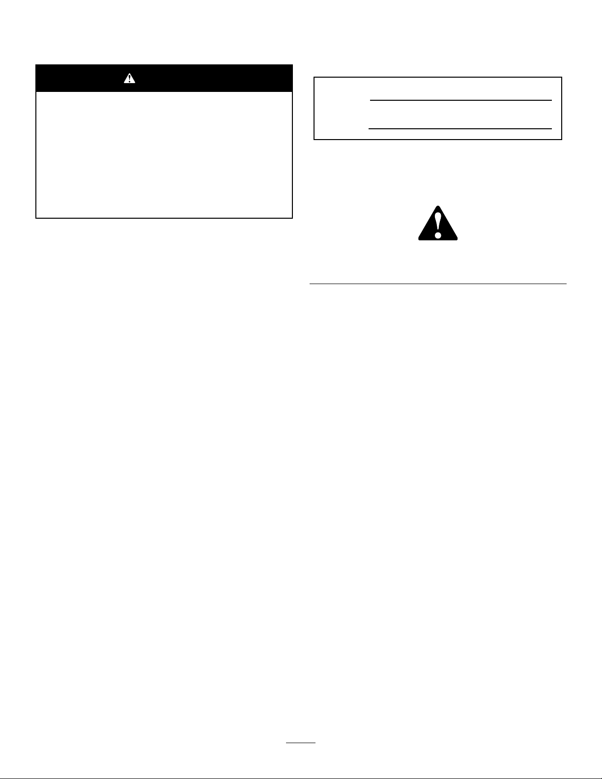
1.Removethebolts,locknuts,andwasherssecuringthe
bottomofthehandlearmstoeachsideofthemachine
(Figure2).
Figure2
1.Mountingpins3.Boltandlocknut
2.Handlearms4.Hairpincotterandringpin
2.Removethehairpincottersandtheringpinssecuring
thehandlearmstotherearoftheframe(Figure2).
1.Handleend
2.Bolt,washer,andlockwasher
5.Securethehandleendstothemountingpinswiththe
bolts,washers,andlockwasherspreviouslyremoved
(Figure3).
6.Securethehandlearmstotherearoftheframewiththe
hairpincottersandtheringpinspreviouslyremoved
(Figure3).
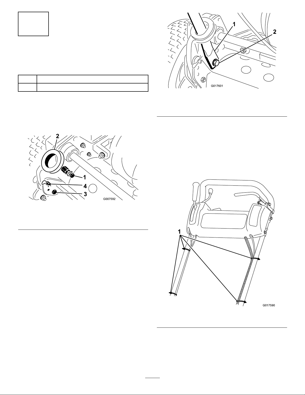
7.Securethecablesandthewiringharnesstothehandle
withthecableties(Figure4).
3.Insertthehandleendsthroughtheholesinthehandle
armsandaligntheholeswiththemountingpins
(Figure2).
4.Squeezethehandleendsinwardandinstallthemonthe
mountingpins(Figure3).
Figure4
1.Cableties
11
Page 12
AdjustingtheHandle
G017948
1
2
3
4
1.Removethehairpincottersfromtheringpinsoneach
sideofthemachine(Figure2).
2.Whilesupportingthehandle,removetheringpins
fromeachsideandraiseorlowerthehandletothe
desiredoperatingposition(Figure2).
3.Installtheringpinsandhairpincotters.
2
InstallingtheKickstand (Models04054and04056)
Partsneededforthisprocedure:
1Kickstandassembly
1
Spring
Procedure
Note:Thefastenersareshippedlooselyinstalledonthe
kickstandassembly .
1.OnModel04056only,connectthespringstudtothe
right-handsideofthekickstand(Figure5)usingthe
bolt,washer,andangenutprovided.
Figure6
1.Kickstand
2.Springbracket4.Spring
3.Mountthekickstandtoeachsideoftheframewith
abolt,lockwasher,spacer,atwasher,andlocknut
(Figure6).
Note:Positionthespacerinthekickstandmounting
hole.
3.Springstud
3
InstallingtheTransportWheel
Shafts(Models04055and
04056)
Partsneededforthisprocedure:
1
Wheelshaft,right
1
Wheelshaft,left
Procedure
1.Pushthekickstanddownwithyourfootandpullupon
thehandletosupportthemachineonthekickstand.
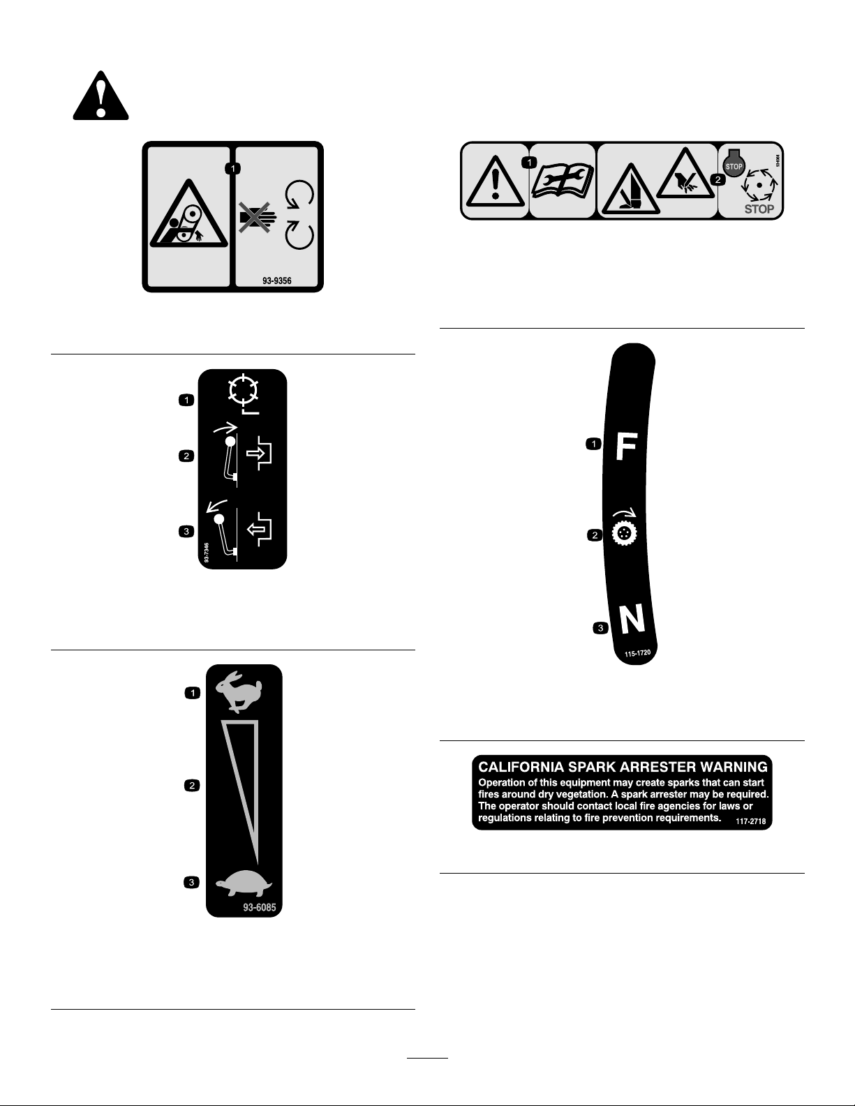
2.Applythread-lockingadhesivetothethreadsofthe
wheelshafts.
3.Threadtherightwheelshaftintothedrivepulleyon
therightsideofthemachine(Figure7).
Figure5
1.Bolt3.Washer
2.Springstud
2.Hookthespringintotheholeinthespringbracketand
ontothespringstudwhilealigningthekickstandwith
themountingholesintherearframe(Figure6).
4.Flangenut
Note:Therightwheelshafthasleft-handthreads.
12
Page 13

Figure7
G017591
1.Rightwheelshaft
4.Torquetheshaftto88to101N-m(65to75ft-lb).
5.Repeattheprocedureontheleftside.
4
InstallingtheTransport Wheels(Optional)
Partsneededforthisprocedure:
2
Transportwheel(optional)
Procedure
1.Slidethewheelontotheaxle(Figure8).
2.Pivotthewheellockingclipawayfromcenterofthe
wheelallowingittoslidefartherontotheaxle(Figure
8).
Figure8
1.Lockingclip
3.Rotatethewheelbackandforthuntilitslides
completelyontotheaxleandthelockingclipissecured
inthegrooveontheaxleshaft.
4.Repeattheprocedureontheoppositesideofthe
machine.
5.Inatethetiresto83to103kPa(12to15psi).
5
AdjustingtheCuttingUnit
NoPartsRequired
Procedure
Beforeoperatingthemachine,completethefollowing
adjustments:
•LevelingtheRearDrumtotheReel(page32)
•AdjustingtheBedknifetotheReel(page33)
•AdjustingtheHeightofCut(page34)
•AdjustingtheGrassShieldHeight(page35)
•AdjustingtheCut-offBar(page35)
13
Page 14

ProductOverview
1
2
3
4
5
6
7
G017592
6
InstallingtheGrassBasket
Partsneededforthisprocedure:
1
Grassbasket
Procedure
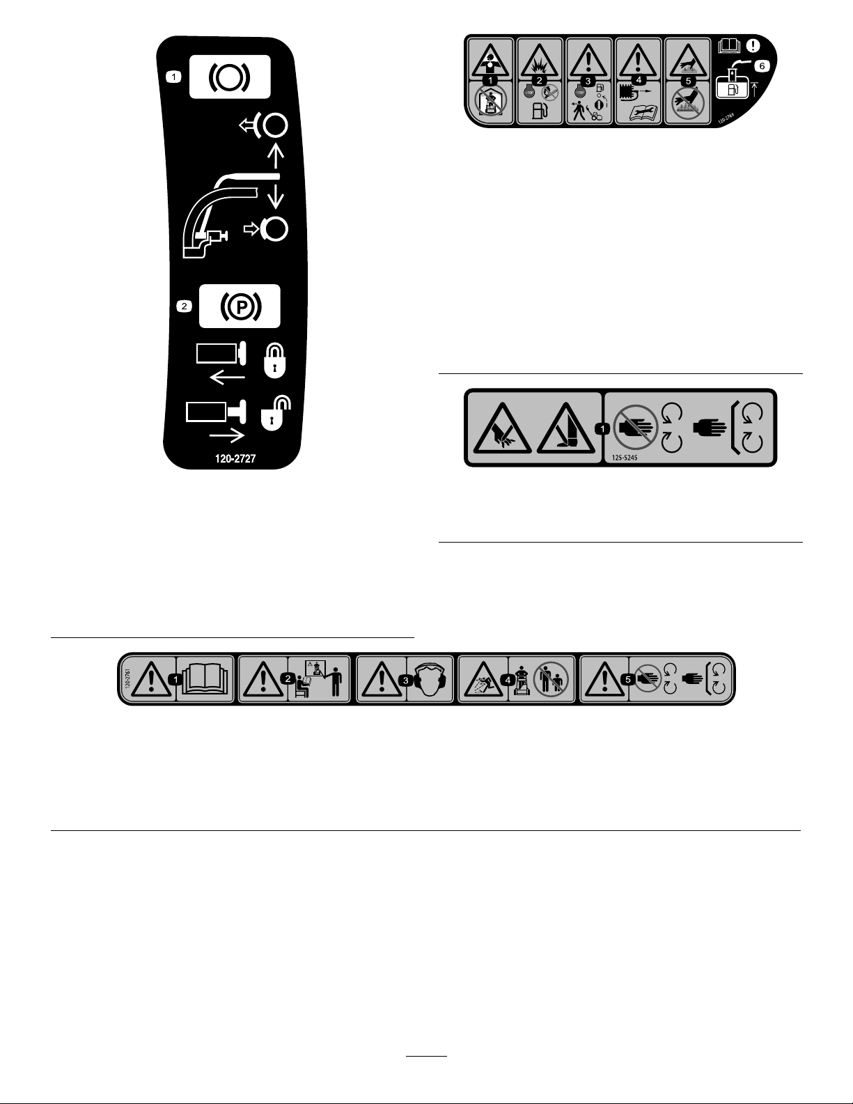
Graspthebasketbythetoplipandslideitontothebasket
mountingrods(Figure9).
Controls
Figure10
1.Traction-drivelever
2.Throttlecontrol6.Parkingbrake
3.On/offswitch7.Operatorpresencecontrol
4.Hourmeter
5.Servicebrake
(optional)
Figure9
1.Grassbasket
Note:Model04056only—Whencuttinginhigherheights
ofcut,youcanlowerthebasketbyremovingeachbasket
mountingrodandinstallingeachontheoppositesideofthe
machine.
2.Basketmountingrod
ThrottleControl
Thethrottlecontrol(Figure10)islocatedontherearright
sideofthecontrolpanel.Theleverconnectstoandoperates
thethrottlelinkagetothecarburetor.RefertoSpecications
(page16)fortheenginespeed.
Traction-driveLever
Thetraction-drivelever(Figure10)islocatedonthefront
rightsideofthecontrolpanel.Ithas2positions:Neutral
andForward.Pushingtheleverforwardengagesthetraction
drive.
ServiceBrake
Theservicebrake(Figure11)islocatedonthetopleftfront
sideofthecontrolpanel.Youcanusethebraketoslowor
stopthemachine.
14
Page 15

G016976
Figure11
G016977
G016978
1
1
g024364
2
Reel-driveLever
Thereel-drivelever(Figure13)islocatedontherightfront
cornerofthemachine.Theleverhas2positions:Engage
andDisengage.Movetheleverforwardtoengagethereelor
rearwardtodisengagethereel.
ParkingBrake
Theparkingbrake(Figure12)islocatedatthebaseofthe
servicebrake.Fullyengagetheservicebrakeandpushthe
parkingbrakeknobtoallowtheservicebraketorestonthe
parkingbrakepin.Engagetheservicebraketoreleasethe
parkingbrake.Youmustreleasethebrakebeforethetraction
driveisengaged.
Figure12
Figure13
1.Reel-drivelever
ChokeLever
Thechokelever(Figure14)islocatedontheleftfrontofthe
engine.Theleverhas2positions:RunandChoke.Movethe
levertotheChokepositionwhenstartingacoldengine.After
theenginestarts,movethelevertotheRunposition.
On/OffSwitch
Theon/offswitch(Figure10)islocatedonthetopofthe
controlpanel.MovetheswitchtotheOnpositiontostartthe
1.Chokelever2.Fuelshut-offvalve
engineandtheOffpositiontostoptheengine.
OperatorPresenceControl(Optional)
Ifequipped,theoperatorpresencecontrol(Figure10)is
locatedontherearofthehandle.Pushtheoperatorpresence
controlagainstthehandle.Ifequipped,theoperatorpresence
controlmustbeengagedbeforemovingthetraction-drive
leverortheenginewillstop.
FuelShut-offValve
Thefuelshut-offvalve(Figure14)islocatedontheleftfront
oftheenginenearthechokelever.Thevalvehas2positions:
ClosedandOpen.Movetheleveruptotheclosedposition
whenstoringortransportingthemachine.Openthevalve
beforestartingtheenginebyrotatingtheleverdown.
15
Figure14
Page 16

Recoil-startHandle
Pulltherecoil-starthandle(Figure15)tostarttheengine.
Figure15
1.Recoil-starthandle2.Kickstand
Kickstand
Thekickstand(Figure15)ismountedtotherearofthe
machineandisusedtoraisetherearofthemachinefor
installationorremovalofthetransportwheels.
Specications
Width
Height
Lengthwith
basket
Dryweight
(withbasket
andWiehle
roller;without
wheelsor
grooming
reel)
Widthofcut46cm(18
Heightofcut
Clip3.3mm(0.13
EnginespeedLowidle
Model04054Model04055Model04056
84cm(33
inches)
114cm(45
inches)
122cm(48
inches)
97kg(216lb)100kg(220
inches)
1.6mmto
31.8mm
(0.063to1.25
inches)
inches)
–1565±150
rpm,High
idle–3375
±100rpm
91cm(36
inches)
114cm(45
inches)
122cm(48
inches)
lb)
53cm(21
inches)
1.6mmto
31.8mm
(0.063to1.25
inches)
4.3mm(0.17
inch)
Lowidle
–1565±150
rpm,Highidle
–3375±100
rpm
104cm(41
inches)
122cm(48
inches)
150cm(59
inches)
105kg(232
lb)
66cm(26
inches)
3.1mmto
31.7mm
(0.125to1.25
inches)
5.8mm(0.23
inch)
Lowidle
–1565±150
rpm,Highidle
–3375±100
rpm
Attachments/Accessories
AselectionofToroapprovedattachmentsandaccessoriesis
availableforusewiththemachinetoenhanceandexpand
itscapabilities.ContactyourAuthorizedServiceDealeror
Distributororgotowww .Toro.comforalistofallapproved
attachmentsandaccessories.
16
Page 17

Operation
Note:Determinetheleftandrightsidesofthemachine
fromthenormaloperatingposition.
DANGER
Incertainconditions,gasolineisextremely
ammableandhighlyexplosive.Areorexplosion
fromgasolinecanburnyouandothersandcan
damageproperty.
ThinkSafetyFirst
Pleasecarefullyreadallofthesafetyinstructionsanddecals
inthesafetysection.Knowingthisinformationcouldhelp
youorbystandersavoidinjury.
CheckingtheEngine-oilLevel
Checktheengine-oillevelbeforeeachuseorevery8
operatinghours,refertoCheckingtheEngine-oilLevel(page
24)inEngineMaintenance(page24).
FillingtheFuelTank
Note:Thefueltankcapacityis2.7liters(2-3/4USqt).
•Forbestresults,useonlyclean,fresh(lessthan30days
old),unleadedgasolinewithanoctaneratingof87or
higher((R+M)/2ratingmethod).
•Ethanol:Gasolinewithupto10%ethanol(gasohol)
or15%MTBE(methyltertiarybutylether)byvolume
isacceptable.EthanolandMTBEarenotthesame.
Gasolinewith15%ethanol(E15)byvolumeisnot
approvedforuse.Neverusegasolinethatcontains
morethan10%ethanolbyvolume,suchasE15
(contains15%ethanol),E20(contains20%ethanol),or
E85(containsupto85%ethanol).Usingunapproved
gasolinemaycauseperformanceproblemsand/orengine
damagewhichmaynotbecoveredunderwarranty.
•Donotusegasolinecontainingmethanol.
•Donotstorefueleitherinthefueltankorfuelcontainers
overthewinterunlessafuelstabilizerisused.
•Donotaddoiltogasoline.
•Fillthefueltankoutdoors,inanopenarea,
whentheengineiscold.Wipeupanygasoline
thatspills.
•Neverllthefueltankinsideanenclosedtrailer.
•Donotllthefueltankcompletelyfull.Add
gasolinetothefueltankuntilthelevelis6to13
mm(1/4to1/2inch)belowthebottomofthe
llerneck.Thisemptyspaceinthetankallows
gasolinetoexpand.
•Neversmokewhenhandlinggasoline,andstay
awayfromanopenameorwheregasoline
fumesmaybeignitedbyaspark.
•Storegasolineinanapprovedcontainerand
keepitoutofthereachofchildren.Neverbuy
morethana30-daysupplyofgasoline.
•Donotoperatewithoutentireexhaustsystemin
placeandinproperworkingcondition.
DANGER
Incertainconditionsduringfueling,static
electricitycanbereleasedcausingasparkwhich
canignitethegasolinevapors.Areorexplosion
fromgasolinecanburnyouandothersandcan
damageproperty.
•Alwaysplacegasolinecontainersontheground
awayfromyourvehiclebeforelling.
•Donotllgasolinecontainersinsideavehicleor
onatruckortrailerbedbecauseinteriorcarpets
orplastictruck-bedlinersmayinsulatethe
containerandslowthelossofanystaticcharge.
•Whenpractical,removeequipmentfromthe
truckortrailerandfuelitontheground.Ifthis
isnotpossible,thenfuelsuchequipmentwith
aportablecontainer,ratherthanfromafuel
dispensernozzle.
•Ifagasolinedispensernozzlemustbeused,
keepthenozzleincontactwiththerimofthe
fueltankorcontaineropeningatalltimesuntil
fuelingiscomplete.
17
Page 18

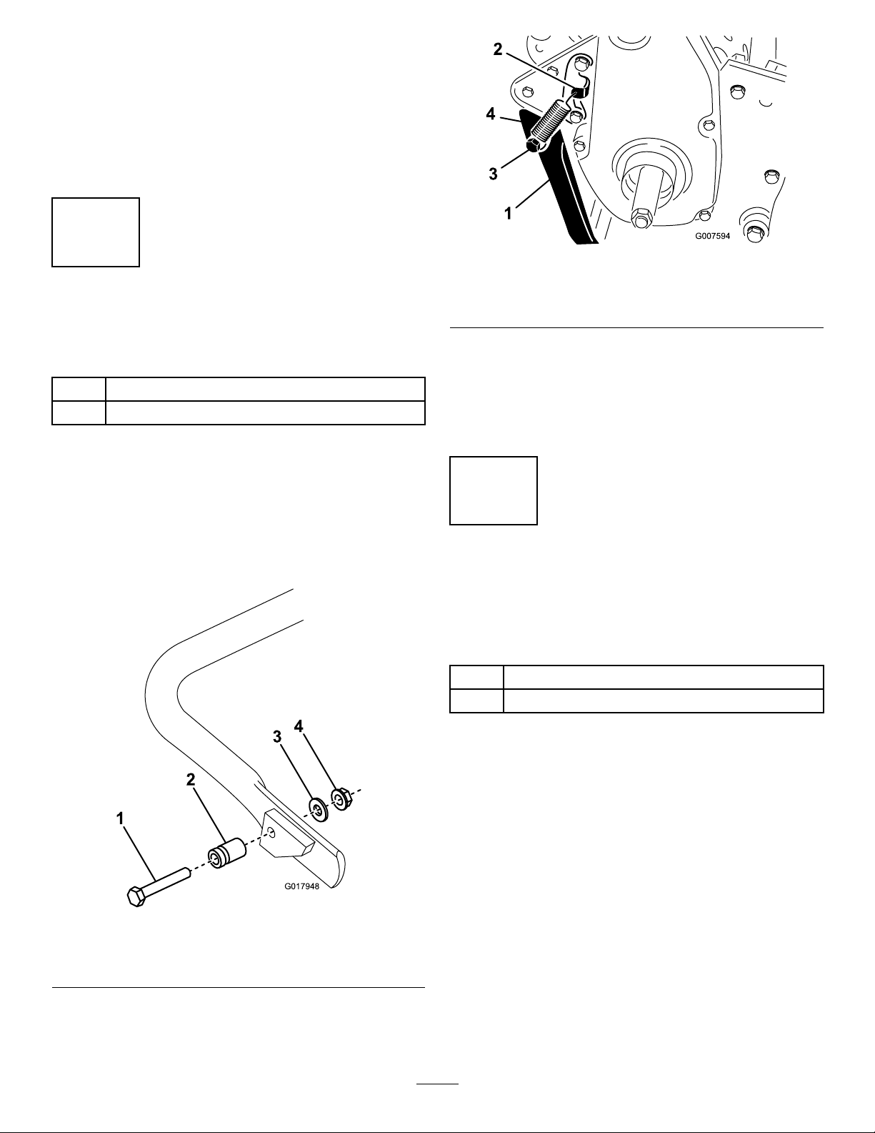
WARNING
G017594
1
Gasolineisharmfulorfatalifswallowed.Long-term
exposuretovaporscancauseseriousinjuryand
illness.
break-in;refertoAdjustingtheService/ParkingBrake(page
27).
CheckingtheInterlockSwitch
•Avoidprolongedbreathingofvapors.
•Keepfaceawayfromnozzleandgastankor
conditionerbottleopening.
•Avoidcontactwithskin;washoffspillagewith
soapandwater.
1.Cleanaroundthefuel-tankcapandremovethecap
fromthetank(Figure16).
Figure16
1.Fuel-tankcap
Operation
CAUTION
Ifsafetyinterlockswitchesaredisconnectedor
damagedthemachinecouldoperateunexpectedly
causingpersonalinjury.
•Donottamperwiththeinterlockswitches.
•Checktheoperationoftheinterlockswitches
dailyandreplaceanydamagedswitchesbefore
operatingthemachine.
1.Pushthekickstanddownwithyourfootandpullup
andbackonthehandletoraisethewheelsoffthe
ground.
2.PlacethetractionleverintotheEngagepositionand
theenginecontrolsinthestartingposition.
3.Attempttostarttheengine.
Theengineshouldnotstart.Iftheenginestarts,the
interlockswitchneedsservice.Correcttheproblem
beforeoperating.
2.Usingunleadedgasoline,llthefueltanknohigher
thanthebottomofthelterscreen.
Note:Thisspaceallowsthegasolinetoexpand.Do
notllthefueltankcompletelyfull.
3.Installfuel-tankcapandwipeupanyspilledgasoline.
Breaking-intheMachine
Refertotheenginemanualsuppliedwiththemachineforoil
changeandmaintenanceproceduresrecommendedduring
thebreak-inperiod.
Only8hoursofmowingoperationisrequiredforthebreak-in
period.
Sincethersthoursofoperationarecriticaltofuture
dependabilityofthemachine,monitoritsfunctionsand
performancecloselysothatminordifculties,whichcould
leadtomajorproblems,arenotedandcanbecorrected.
Inspectthemachinefrequentlyduringbreak-inforsignsof
oilleakage,loosefasteners,oranyothermalfunction.
Toensureoptimumperformanceofthebrakesystem,burnish
(break-in)thebrakesbeforeusingthemachine.Toburnish
thebrakes,rmlyapplythebrakesanddrivethemachineat
mowingspeeduntilthebrakesarehot,asindicatedbytheir
smell.Anadjustmenttothebrakesmayberequiredafter
4.Carefullyliftuponthehandletoreleasethekickstand.
18
Page 19

StartingandStoppingthe Engine
Note:Forillustrationsanddescriptionsofthecontrols
referencedinthissection,refertotheControls(page14)
sectioninProductOverview(page14).
StartingtheEngine
Note:Ensurethatthespark-plugwireisinstalledonthe
sparkplug.
1.Ensurethatthetractionandreel-driveleversareinthe
Disengagedposition.
Note:Theenginewillnotstartifthetractionleveris
intheEngagedposition.
2.Openthefuelshut-offvalveontheengine.
3.Movetheon/offswitchtotheOnposition.
4.MovethethrottlecontroltotheFastposition.
5.MovethechokeleverhalfwaybetweentheOnandOff
positionswhenstartingacoldengine.Thechokemay
notberequiredwhenstartingawarmengine.
6.Pulltherecoil-starthandleoutuntilpositive
engagementresults,thenpullitvigorouslytostartthe
engine.
Important:Donotpulltherecoilropetothe
limitorletgoofthestarterhandlewhentherope
ispulledout,becausetheropemaybreakorthe
recoilassemblymaybedamaged.
7.MovethechoketotheOffpositionastheengine
warmsup.
TransportingtheMachine
1.Ifthemachineisequippedwiththeoptionaltransport
wheels,pushthekickstanddownwithyourfootand
pulluponthehandletoraisetherearofthemachine
andinstallthetransportwheels.
2.Toreleasethekickstand,pulluponthehandle,push
themachineforward,andthenlowertherearofthe
machineontothetransportwheels.
3.Ensurethatthetractionandreeldrivecontrolsarein
theDisengagedpositionandstarttheengine.
4.SetthethrottlecontroltoSlow ,raisethefrontofthe
machineupslightly ,graduallyengagethetractiondrive
andslowlyincreasetheenginespeed.
5.Adjustthethrottletooperatethemachineatthe
desiredgroundspeedandtransportthemachinetothe
desireddestination.
6.Returnthetraction-controllevertotheDisengage
position,thethrottletotheSlowposition,andstop
theengine.
PreparingtoMow
1.Ifthemachineisequippedwiththeoptionaltransport
wheels,pushthekickstanddownwithyourfootand
pullupandbackonthehandletoraisethewheelsoff
theground.
2.Pushthelockingclipsonthewheelsoutofthegrooves
intheshafts.
3.Slidethewheelsofftheshafts.
4.Movethemachineoffthekickstand.
Mowing
StoppingtheEngine
1.Movethetractionandreeldrivecontrolstothe
Disengagedposition,thethrottlecontroltotheSlow
position,andtheOn/OffswitchtotheOffposition.
2.Pullthespark-plugwireoffthesparkplugtoprevent
thepossibilityofaccidentalstartingbeforestoringthe
machine.
3.Closethefuelshut-offvalvebeforestoringor
transportingthemachineinavehicle.
Properuseofthemachineprovidesthesmoothestturf
cuttingavailable.ReferalsotoOperatingTips(page20)for
fundamentalsuggestionstoobtaintheutmostperformance
fromyourmachine.
Important:Excessiveoperationofthecuttingunitwith
theabsenceofgrassclippings(lubricant)candamage
thecuttingunit.
1.Starttheengine,setthethrottleatareducedspeed,
pushdownonthehandletoraisethecuttingunit,
movethetractionlevertotheEngagedposition,and
transportthemachineontothecollarofthegreen.
2.MovethetractionlevertotheDisengagedpositionand
movethereel-drivelevertotheEngagedposition.
3.MovethetractionlevertotheEngagedposition,
increasethethrottlespeeduntilthemachineistraveling
atthedesiredgroundspeed,drivethemachineontothe
green,lowerthefrontofthemachine,andcommence
operation.
4.Whenyouarenishedmowing,driveoffthegreen,
movethetraction-controllevertotheDisengaged
19
Page 20

position,stoptheengine,andpushthereel-drivelever
intotheDisengagedposition.
OperatingTips
5.Emptythegrassbasketofclippings,installthegrass
basket,andcommencethetransportoperation.
BeforeMowing
•Ensurethatthemachineiscarefullyadjustedand
issetevenlyonbothsidesofthereel.Improper
machineadjustmentismagniedmanytimesoverinthe
appearanceoftheclippedturf.
•Removeallforeignobjectsfromtheturfpriortomowing.
•Ensurethateveryone,especiallychildrenandpets,are
clearoftheworkarea.
MowingTechniques
•Mowagreeninastraightbackandforthdirection,across
thegreen.
•Avoidcircularmowingorturningthemachineonagreen
becausescufngmayoccur.Turnthemachineoffthe
greenbyraisingthecuttingreel(pushingthehandle
down)andturningonthetractiondrum.
•Mowatanormalwalkingpace.Fastspeedsavesvery
littletimeandwillresultinaninferiormowingjob.
20
Page 21

Maintenance
Note:Determinetheleftandrightsidesofthemachinefromthenormaloperatingposition.
RecommendedMaintenanceSchedule(s)
MaintenanceService
Interval
Aftertherst20hours
Beforeeachuseordaily
Every25hours
Every50hours
Every100hours
Every500hours
Every1,000hours
MaintenanceProcedure
•Changetheengineoil.
•Cleanthefuellterandcup.
•Checktheinterlockswitchoperation.
•Checktheengine-oillevel.
•Greasethemachine(greasethettingsimmediatelyaftereverywashingregardless
oftheintervallisted).
•Changetheengineoil(morefrequentlyindustyordirtyconditions).
•Cleanandoilthefoamair-cleanerelement(moreoftenindirtyordustyconditions).
•Replacethepaperair-lterelement(moreoftenindirtyordustyconditions).
•Checkthesparkplug.
•Cleanthefuellterandcup.
•Checktheintakeandexhaustvalves.Adjustthemasnecessary.
•Cleanthecarburetor.
•Replacethefuelline.
•Checkthetransmissiondrivebelts.
•Checkthetransmissionbearings.
Important:Refertoyourengineoperator'smanualforadditionalmaintenanceprocedures.
21
Page 22

DailyMaintenanceChecklist
Important:Duplicatethispageforroutineuse.
Maintenance
CheckItem
Checkthe
safetyinterlock
operation.
Checkthe
parkingbrake
operation.
Checkthefuel
level.
Checktheengine
oillevel.
Checktheair
lter.
Cleantheengine
coolingns.
Checkfor
unusualengine
noises.
Checkfor
unusual
operatingnoises.
Checkthe
reel-to-bedknife
adjustment.
Checkthe
height-of-cut
adjustment.
Greaseall
ttings.
Touchup
damagedpaint.
Fortheweekof:
Mon.Tues.Wed.Thurs.Fri.
Sat.Sun.
NotationforAreasofConcern
Inspectionperformedby:
ItemDate
Information
22
Page 23

Lubrication
G016993
G016981
G016982
GreasingtheMachine
ServiceInterval:Every25hours
Lubricatethe13greasettingsonthemachineusinga#2
multipurpose,lithium-basedgrease.Ahand-operatedgrease
gunisrecommendedforbestresults.
Thegreasettinglocationsareasfollows:
•2onthefrontroller(Figure17)
•2onthereelbearings(Figure17)
•2onthedrumaxles(Figure18)
•3onthedifferential(Figure18)
•2onthereelcountershaftbearings(Figure19)
•2onthebeltidlerpivots(Figure20).
1.Wipeeachgreasettingwithacleanrag.
2.Pumpgreaseintoeachttinguntilitbeginstoget
difculttopumpthegun.
Important:Donotapplytoomuchpressureor
greasesealswillbecomepermanentlydamaged.
3.Wipeoffanyexcessgrease.
Figure19
Figure20
Figure17
Figure18
23
Page 24

EngineMaintenance
G016983
1
ServicingtheEngineOil
ServiceInterval:Aftertherst20hours—Changethe
engineoil.
Beforeeachuseordaily—Checktheengine-oillevel.
Every50hours—Changetheengineoil(more
frequentlyindustyordirtyconditions).
Thecrankcasemustbelledwithapproximately0.62liter(21
oz)ofproperviscosityoilbeforestarting.Theengineuses
anyhigh-qualityoilwithanAPlserviceclassicationSFor
higher.RefertoFigure21anduseanoilwithaviscositythat
correspondstotheambienttemperature.
CheckingtheEngine-oilLevel
1.Positionthemachinesothattheengineislevel,and
cleantheareaaroundtheoil-levelgauge(Figure22).
Figure22
Figure21
Note:Usingmulti-gradeoils(5W-20,10W -30,and10W -40)
increasesoilconsumption.Checktheoillevelmorefrequently
whenusingthem.
1.Oil-levelgauge
2.Removetheoil-levelgaugebyrotatingit
counterclockwise.
3.Wipetheoillevelgaugecleanandinsertitintotheller
port,butdonotscrewitintotheport.
4.Removethegaugeandchecktheleveloftheoil.
5.Ifthelevelislow,addonlyenoughoiltoraisethe
leveluntilitisbetweenthehatchmarksonthegauge
(Figure23).
Important:Donotoverllthecrankcase.
2.Drainplug
Figure23
1.Hatchmarks
6.Installtheoillevelgaugeandwipeupanyspilledoil.
24
Page 25

ChangingtheEngineOil
1
G016984
G016985
1
2
3
4
5
1.Startandruntheengineforafewminutestowarm
theengineoil.
2.Placeadrainpanattherearofmachine,underthe
drainplug(Figure22).
3.Removethedrainplug.
4.Pushdownonthehandletotipthemachineandthe
enginebackward,allowingmoreoiltorunintothe
drainpan.
5.Installthedrainplugandllthecrankcasewiththe
properoil;refertoServicingtheEngineOil(page24).
ServicingtheAirCleaner
ServiceInterval:Every50hours—Cleanandoilthefoam
air-cleanerelement(moreoftenindirty
ordustyconditions).
Every100hours—Replacethepaperair-lterelement
(moreoftenindirtyordustyconditions).
Figure25
1.Wingnut4.Foamelement
2.Air-cleanercover5.Paperelement
3.Plasticwingnut
Important:Servicetheaircleanermoreoftenindirty
ordustyconditions
1.Makesurethatthewireisoffthesparkplug.
2.Removethewingnutsecuringtheair-cleanercoverand
removethecover(Figure24).
5.Checktheconditionofthepaperelement.Cleanitby
gentlytappingorreplaceitasrequired.
Important:Donotusecompressedairtoclean
thepaperelement.
6.Installthefoamelement,paperelement,andaircleaner
cover.
Important:Donotoperatetheenginewithoutthe
air-cleanerelementbecauseextremeenginewear
anddamagewilllikelyresult.
Figure24
1.Air-cleanercover
3.Cleanthecoverthoroughly.
4.Ifthefoamelementisdirty ,removeitfromthepaper
element(Figure25)andcleanitthoroughly,asfollows:
A.Washthefoamelementinasolutionofliquid
soapandwarmwater.Squeezeittoremovedirt,
butdonottwistitbecausethefoammaytear.
B.Drythefoamelementbywrappingitinaclean
rag.Squeezetheragandfoamelementtodryit,
butdonottwistit.
C.Saturatethefoamelementwithcleanengineoil.
Squeezetheelementtoremoveexcessoilandto
distributetheoilthoroughly.Anoildampelement
isdesirable.
25
Page 26

ReplacingtheSparkPlug
G016986
1
G019300
1 2
4
3
G016988
1
2
FuelSystem
ServiceInterval:Every100hours
UseanNGKBR6HSsparkplugorequivalent.Thecorrect
airgapis0.6to0.7mm(0.024to0.028inch).
1.Pullthemoldedwireoffthesparkplug(Figure26).
Figure26
1.Spark-plugwire
2.Cleanaroundthesparkplugandremoveitfromthe
cylinderhead.
Maintenance
CleaningtheFuelFilter
ServiceInterval:Aftertherst20hours
Every100hours
1.Closethefuelshut-offvalveandunscrewthebowl
fromthelterbody(Figure28).
Important:Replaceacracked,fouled,ordirty
sparkplug.Donotsandblast,scrape,orclean
electrodesbecauseenginedamagecouldresult
fromgritenteringthecylinder.
3.Ensurethattheairgapiscorrect(Figure27).
Figure27
1.Sideelectrode
2.Centerelectrode4.0.6to0.7mm(0.024to
4.Installthecorrectlygappedsparkplugandtightenit
to23N-m(17ft-lb).
5.Installthespark-plugwireonthesparkplug.
3.Insulator
0.028inch)gap
Figure28
1.Bowl
2.Cleanthebowlandlterincleangasolineandinstallit.
2.Fuelshut-offvalve
26
Page 27

ElectricalSystem
G016989
1
2
3
4
G016990
Maintenance
BrakeMaintenance
AdjustingtheService/Parking
ServicingtheInterlockSwitch
Usethefollowingprocedureiftheswitchneedsadjustment
orreplacement.
1.Makesurethattheengineisoffandthetractionleveris
disengagedandrestingagainsttheneutralstop(Figure
29).
Brake
Iftheservice/parkingbrakeslipswhenoperated,an
adjustmentisrequired.
1.Engagetheservicebrake,pushinontheparkingbrake
knobandallowtheservicebraketorestontheparking
brakepin(Figure30).
Figure29
1.Tractionlever3.Interlockswitch
2.Neutralstop
2.Loosentheinterlockswitchmountingfasteners(Figure
29).
3.Placea0.8mm(.032inch)thickshimbetweenthe
tractionleverandtheinterlockswitch(Figure29).
4.Tightentheinterlockswitchmountingfastenersand
checkthegapagain.
Note:Thetractionlevermustnotcontacttheswitch.
5.Engagethetractionleverandverifythattheswitch
losescontinuity .
Note:Replacetheswitchifrequired.
4.0.8mm(0.032inch)gap
Figure30
2.Usingaspringscale,pressrearwardontheservice-brake
lever(Figure31).Theparkingbrakeshouldrelease
whenaforceof13.5to18kg(30to40lb)isattained.
Iftheparkingbrakereleasesbefore13.5to18kg(30to
40lb)offorceisattained,anadjustmenttothebrake
cableisrequired.Proceedtostep3.
27
Page 28

G016991
1
2
Figure33
Figure31
1.Rearpressureontheservice-brakelever
3.LoosentheretainersecuringtheV-beltcoverandpivot
thecoveropen(Figure32).
Figure32
1.V–beltcover2.Retainer
1.Service/parkingbrake
cable
2.Frontjamnut
5.Closethecoverandsecuretheretainer.
4.Toadjustthebrakecabletension,proceedasfollows.
•Todecreasethecabletension,loosenthefront
cablejamnutandtightentherearjamnut(Figure
33).Repeatsteps1and2andreadjustifrequired.
•Toincreasethecabletension,tightenthefront
cablejamnutandloosentherearjamnut(Figure
33).Repeatsteps1and2andreadjustifrequired.
Note:Theadjustmentcanbeperformedonthe
cableatthejamnutbracketsbythecontrolpanel
oratthebracketatthebaseoftheengine.
28
Page 29

BeltMaintenance
AdjustingtheBelts
Ensurethatthebeltsareproperlytensionedtoensureproper
operationofthemachineandpreventunnecessarywear.
Checkthebeltsfrequently.
5.Whilemaintainingaslightgapbetweenthecoverseal
andthesideplate,installeachmountingboltuntilthe
threadsengageintheinsert.
Note:Thegapallowsvisualalignmentoftheboltsto
thethreadedinserts.
6.Afterallboltsareinstalled,tightenthemuntilthe
stand-offsinsidethecovercontactthesideplate.
AdjustingtheReelDriveBelt
1.Removethebeltcovermountingfastenersandthebelt
covertoexposethebelt(Figure34).
Figure34
1.Beltcover
2.Checkthetensionbypressingthebeltatmidspanof
thepulleys(Figure35)with18to22N(4to5lb)of
force.Thebeltshoulddeect6mm(1/4inch).
Note:Donotovertightenthebolts.
AdjustingtheTractionDriveBelt
1.Removethebelt-covermountingfastenersandthebelt
covertoexposethebelt(Figure36).
Figure36
1.Tractiondrive-beltcover
2.Checkthetensionbypressingthebeltatmidspanof
thepulleys(Figure37)with18to22N(4to5lb)of
force.
Figure35
1.Reeldrivebelt2.Idlerpulley
3.Completethefollowingtoadjustthebelttension:
A.Loosentheidler-pulleymountingnutandpivot
theidlerpulleyclockwiseagainstthebacksideof
thebeltuntilyouattainthedesiredbelttension
(Figure35).
Important:Donotover-tensionthebelt.
B.Tightenthenuttolocktheadjustment.
4.Installthebeltcoverbyplacingitinposition.
Note:Thebeltshoulddeect6mm(1/4inch).
Figure37
1.Tractiondrivebelt2.Idlerpulley
3.Completethefollowingtoadjustthebelttension:
A.Loosentheidler-pulleymountingnutandpivot
theidlerpulleyclockwiseagainstthebacksideof
thebeltuntilthedesiredbelttensionisattained
(Figure37).
Important:Donotover-tensionthebelt.
29
Page 30

B.Tightenthenuttolocktheadjustment.
G016991
1
2
AdjustingthePrimaryV-Belts
4.Installthebeltcoverbyplacingitinposition.
5.Whilemaintainingaslightgapbetweenthecoverseal
andthesideplate,installeachmountingboltuntilthe
threadsengageintheinsert.
Note:Thegapallowsvisualalignmentoftheboltsto
thethreadedinserts.
6.Afterallboltsareinstalled,tightenthemuntilthe
stand-offsinsidethecovercontactthesideplate.
Note:Donotovertightenthebolts.
AdjustingtheDifferentialBelt
1.Removetheboltssecuringthefrontandrearsections
ofthedifferentialcovertothedifferentialhousingand
slidethecoversectionsawaytoexposethebelt.
2.Checkthetensionbypressingthebeltatmidspanof
thepulleys(Figure38)with22to26N(5to6lb)of
force.
Note:Thebeltshoulddeect6mm(1/4inch).
1.ToadjustthebelttensiononprimaryV -belts,rst
checktheadjustmentofthetractioncontrol;refer
toAdjustingtheTractionControl(page32).Ifyou
areunabletoattainthe18to22N(4to5lb)force
requiredinadjustingthetractioncontrol,proceedto
thenextstep.
2.LoosentheretainersecuringtheV-beltcoverandpivot
thecoveropen(Figure39).
Figure39
Figure38
1.Differentialbelt
2.Idlerpulley
3.Completethefollowingtoadjustthebelttension:
A.Loosentheidlerpulleymountingnutandpivot
theidlerpulleyclockwiseagainstthebacksideof
thebeltuntilthedesiredbelttensionisattained
(Figure38).
Important:Donotover-tensionthebelt.
B.Tightenthenuttolocktheadjustment.
1.V-beltcover2.Retainer
3.Toincreasebelttension,loosentheenginemounting
boltsandmovetheenginebackwardsintheslots.
Important:Donotover-tensionthebelt.
4.Tightenthemountingbolts.
Note:Thedistancebetweenthecenterofthedrive
pulleyandthecenterofthedrivenpulleyshouldbe
approximately12.85cm(5.06inches)afternewV -belts
areinstalled.
5.AftertensioningtheprimaryV -belts,checkthe
alignmentoftheengineoutput-shaftpulleyandthe
counter-shaftpulleywithastraightedge.
6.Ifthepulleysaremisaligned,loosenthescrewssecuring
theenginemountingbasetothemachineframeand
slidetheenginefromsidetosideuntilthepulleysare
alignedwithin0.7mm(0.030inch).
4.Installthebeltcoverbyplacingitinposition.
5.Whilemaintainingaslightgapbetweenthecoverseal
andthesideplate,installeachmountingboltuntilthe
threadsengageintheinsert.Thegapallowsvisual
alignmentoftheboltstothethreadedinserts.
6.Afterallboltsareinstalled,tightenthemuntilthe
stand-offsinsidethecovercontactthesideplate.Do
notovertightenthebolts.
30
Page 31

G016992
1
2
3
4
Figure40
1.Locknut3.Idlerpulley
2.Beltguide4.Idlerarm
7.Tightenthemountingscrewsandcheckthealignment.
8.Topushorpullthemachineeasierwithoutstarting
theengine,adjustthebeltguide(Figure40,inset)as
follows:
A.Engagetheclutch.
B.Loosenthelocknutsecuringtheidlerpulleyand
thebeltguidetotheidlerarm.
C.Rotatethebeltguideclockwiseuntilagapof
approximately1.5mm(0.06inch)isobtained
betweentheguidengerandthebacksideofthe
drivebelts.
D.Tightenthelocknutsecuringtheidlerpulleyand
thebeltguidetotheidlerarm.
9.Closethecoverandsecuretheretainer.
Figure41
1.Differentialcoversections
2.Frontclutchhousing
3.Rightrearbearinghousing
5.Loosentheidlerpulleymountingnutonthedifferential
idlerpulleyandpivottheidlerpulleycounterclockwise
awayfromthebacksideofthebelttoreleasethebelt
tension.
6.Removethe2boltsandlocknutssecuringthefront
clutchhousingtothesideplate(Figure41).
7.Rotatethehousing180°sothatthebottomofthe
housingpointsupward.
8.Removethe2boltsandlocknutssecuringtherightrear
bearinghousingtothesideplate(Figure41).
9.Rotatethehousing180°sothatthebottomofthe
housingpointsupward.
10.Removetheoldbelt.
11.Slidethenewbeltovertherotatedhousingcoversand
thedifferentialcoversections,andontothedifferential
pulleys.
ReplacingtheDifferentialBelt
1.Removetheboltssecuringthetractiondriveandreel
drivebeltcoverstotherightsideplateandremovethe
beltcovers.
2.Loosentheidlerpulleymountingnutoneachidler
pulleyandpivoteachidlerpulleycounterclockwise
awayfromthebacksideofeachbelttoreleasethebelt
tension.
3.Removethebelts.
4.Removetheboltssecuringthefrontandrearsections
ofthedifferentialcovertothedifferentialhousingand
slidethecoversectionsawaytoexposethebelt(Figure
41).
12.Ensurethattheidlerpulleyispositionedagainstthe
backsideofthebelt.
13.Rotatebothhousingsbackintotheuprightposition
andsecurethemtothesideplatewiththeboltsand
nutspreviouslyremoved.
14.Adjustthedifferentialbelttension;refertoAdjusting
theDifferentialBelt(page30).
15.Adjustthebelttensiononthetractiondriveandreel
drivebelts;refertoAdjustingtheTractionDriveBelt
(page29),andAdjustingtheReelDriveBelt(page29).
16.Installthedifferential,tractiondrive,andreeldrive
covers.
31
Page 32

ControlsSystem
Maintenance
CuttingUnitMaintenance
LevelingtheRearDrumtothe
AdjustingtheTractionControl
Ifthetractioncontroldoesnotengageoritslipsduring
operation,anadjustmentisrequired.
1.MovethetractioncontroltotheDisengagedposition.
2.LoosentheretainersecuringtheV-beltcoverandpivot
thecoveropen(Figure39).
3.Toincreasethecabletension,loosenthefrontcable
jamnutandtightenthebackcablejamnut(Figure
42)untilaforceof3to4kg(7to9lb)isrequiredto
engagethetractioncontrol.
Note:Measuretheforceatthecontrolknob.
Reel
1.Positionthemachineonaat,levelsurface,preferably
aprecisionsteelworkplate.
2.Placea0.6x2.5cm(1/4x1inch)atsteelstrip,
approximately73.6cm(29inches)long,underthereel
bladesandagainstthefrontedgeofthebedknifeto
preventthebedbarfromrestingontheworksurface.
3.Raisethefrontrollersothatonlythereardrumand
thereelareonthesurface.
4.Firmlypressdownonthemachineabovethereelso
thatallreelbladescontactthesteelstrip.
5.Whilepressingdownonthereel,slideafeelergauge
underoneendofthedrum,thenchecktheotherend
ofthedrum.
Note:Ifthereisagapbetweenthedrumandthe
worksurface,greaterthan0.25mm(0.010inch),on
eitherend,adjustthedrum(proceedtostep6).Ifthe
gapislessthan0.25mm(0.010inch)noadjustment
isrequired.
6.Removetherearbeltcoverfromtherightsideofthe
machine(Figure43).
Figure42
1.Tractioncable2.Frontjamnut
4.Tightenthefrontcablejamnut.
5.Closethecoverandsecuretheretainer.
6.Checkthetractioncontroloperation.
Figure43
1.Tractiondrive-beltcover
7.Rotatethedrivenpulleyuntiltheholesalignwiththe4
rollerbearingangescrews(Figure44).
32
Page 33

5.Insertthe0.05mm(0.002inch)shimbetweenthe
markedbladeandthebedknifeedgeatthepointwhere
themarkedbladecrossesthebedknifeedge.
6.Turntherightbedbaradjustingscrewuntilyoufeel
lightpressure(i.e.drag)ontheshimbyslidingit
side-to-side(Figure45).
7.Removetheshim.
8.Fortheleftsideofthecuttingunit,slowlyrotatethe
reelsothattheclosestbladecrossesthebedknifeedge
betweentherstandsecondscrewheads.
Figure44
1.Drivenpulley3.IdlerPulley
2.4holes
8.Loosenthe4rollerbearingscrewsandthescrew
securingtheidlerpulley.
9.Raiseorlowertherightsideoftherollerassemblyuntil
thegapislessthan0.25mm(0.010inch).
10.Tightentherollerbearingscrews.
11.Adjustthebelttensionandtightentheidlerpulley
mountingscrew(Figure44).
AdjustingtheBedknifetothe Reel
Note:Usethisprocedureaftergrinding,backlapping,or
disassembly.Itisnotintendedasadailyadjustment.
1.Positionthemachineonaat,levelworksurface.
2.Tiltthemachinebackonthehandletoexposethe
bedknifeandthereel.
9.Repeatsteps4through7fortheleftsideofthecutting
unitandleftbedbaradjustingscrew.
10.Repeatsteps5through7untillightdragisachievedon
boththerightandleftsidesofthecuttingunitutilizing
thesamecontactpoints.
11.Toobtainlightcontactbetweenthereelandbedknife,
turneachbedbaradjustingscrewclockwise3clicks.
Note:Eachclickturnedonthebedbaradjustingscrew
movesthebedknife0.018mm(0.0007inch).Clockwise
rotationmovesthebedknifeedgeclosertothereel
andcounterclockwiserotationmovethebedknifeedge
awayfromthereel.
12.Testthecuttingperformancebyinsertingalongstrip
ofcuttingperformancepaperbetweenthereeland
bedknife,perpendiculartothebedknife(Figure46).
Slowlyrotatethereelforward;itshouldcutpaper.
Important:Donottiltthemachinebackfurther
than60degreestopreventfuelleakage.
3.Rotatethereelsothatabladecrossesthebedknifeedge
betweentherstandsecondbedknifescrewheadson
therightsideofthecuttingunit(Figure45).
Figure45
1.Bedbaradjustingscrew
4.Rotatethereelsothatabladecrossesthebedknifeedge
betweentherstandsecondbedknifescrewheadson
therightsideofthecuttingunit.
Figure46
Note:Ifexcessivecontact/reeldragisevidentitwill
benecessarytobacklap,facethefrontofthebedknife,
orgrindthecuttingunittoachievethesharpedges
neededforprecisioncutting.
33
Page 34

AdjustingtheHeightofCut
1.Verifythattherearrollerislevelandthatthe
bedknife-to-reelcontactiscorrect.Tipthemachine
backonthehandletoexposethefrontandrearrollers
andthebedknife.
2.Loosenthelocknutssecuringtheheight-of-cutarmsto
theheight-of-cutbrackets(Figure47).
Figure49
5.Rotatetheadjustingscrewuntiltherollercontactsthe
frontofthegaugebar.
6.Adjustbothendsoftherolleruntiltheentirerolleris
paralleltothebedknife.
Figure47
1.Height-of-cutarm
2.Height-of-cutbracket
3.Locknut
4.Adjustingscrew
3.Loosenthenutonthegaugebar(Figure48)andset
theadjustingscrewtothedesiredheightofcut.The
distancebetweenthebottomofthescrewheadandthe
faceofthebaristheheightofcut.
Figure48
1.Gaugebar
2.Height-adjustingscrew
3.Nut
Important:Whensetproperly,therearandfront
rollerswillcontactthegaugebarandthescrew
willbesnugagainstthebedknife.Thisensures
thattheheightofcutisidenticalatbothendsof
thebedknife.
7.Tightennutstolocktheadjustment.
Important:Toavoidscalpingonundulatingturf,
ensurethattherollersupportsarepositioned
rearward(therollerclosertothereel).
Note:Thefrontrollercanbeputin3different
positions(Figure50),dependingontheapplicationand
needsoftheuser.
•Usethefrontpositionwhenagroomerisinstalled.
•Usethemiddlepositionwithoutagroomer.
•Usethethirdpositioninextremelyundulatingturf
conditions.
4.Hookthescrewheadonthecuttingedgeofthe
bedknifeandresttherearendofthebarontherear
roller(Figure49).
Figure50
34
Page 35

AdjustingtheGrassShield Height
Adjusttheshieldtoensurepropergrassclippingdischarge
intothebasket.
1.Measurethedistancefromthetopofthefrontsupport
rodtothefrontlipoftheshieldateachendofthe
cuttingunit(Figure51).
Figure51
1.Supportrod2.Shield
2.Theheightoftheshieldfromthesupportrodfor
normalcuttingconditionsshouldbe10cm(4inches).
Loosentheboltsandnutssecuringeachendofthe
shieldtothesideplateandadjusttheshieldtothe
correctheight.
Note:Thebarisadjustabletocompensateforchanges
inturfconditions.Adjustthebarclosertothereel
whentheturfisextremelywet.Bycontrast,adjustthe
barfurtherawayfromthereelwhenturfconditionsare
dry.Thebarshouldbeparalleltothereeltoensure
optimumperformance.Adjustthebarwheneverthe
shieldheightisadjustedorwhenthereelissharpened
onareelgrinder.
BedbarIdentication
Todetermineifthebedbarisstandardoraggressive,check
theleftbedbarmountingears.Ifthemountingearsare
roundeditisastandardbedbar.Ifthemountingearshavea
notchinthem,itisanaggressivebedbar(Figure53).
Figure53
1.Standardbedbar
2.Aggressivebedbar
3.Tightenthefasteners.
Note:Youcanlowertheshieldfordrierconditions
(clippingsyoverthetopofthebasket)orraiseitto
allowforheavy,wetgrassconditions(clippingsbuild
upontherearofthebasket).
AdjustingtheCut-offBar
Adjustthecut-offbartoensurethattheclippingsarecleanly
dischargedfromthereelarea.
1.Loosenthescrewssecuringthetopbar(Figure52)to
thecuttingunit.
Figure52
1.Cut-offbar
2.Inserta1.5mm(0.060inch)feelergaugebetweenthe
topofthereelandthebarandtightenthescrews.
3.Ensurethatthebarandreelareequaldistancesapart
acrosstheentirereel.
35
Page 36

SettingtheMachinetoMatchTurfConditions
Usethefollowingtabletosetthemachinetomatchturfconditions.
GreensmowerCuttingUnitSetupMatrix
Bedbars:StandardandOptional
PartNumberDescriptionMowerAggressiveness
120-2682-03
112-9281-01
112-9279-03Aggressive
112-9280-01
110-9278-03Aggressive
Bedknives:StandardandOptional
PartNumberDescriptionMower
98-7261Microcut
117-1530EdgeMaxMicrocut
98-7260T ournament
117-1532EdgeMaxT ournament
110-2300ExtendedMicrocut
110-2301Lowcut
93-4262Microcut
115-1880EdgeMaxMicrocut
93-4263T ournament
115-1881EdgeMaxT ournament
93-4264Lowcut
108-4303ExtendedMicrocut
112-9275Microcut
94-5885T ournament
104-2646Highcut
93-9015Lowcut
StandardGreensmaster800
StandardGreensmaster
1000
Greensmaster
1000
StandardGreensmaster
1600
Greensmaster
1600
Greensmaster800
Greensmaster800
Greensmaster800
Greensmaster800
Greensmaster800
Greensmaster8006.0mm(0.250inch)andup
Greensmaster
1000
Greensmaster
1000
Greensmaster
1000
Greensmaster
1000
Greensmaster
1000
Greensmaster
1000
Greensmaster
1600
Greensmaster
1600
Greensmaster
1600
Greensmaster
1600
Comments
Less
Less
More
Less
More
HeightofCutRangeComments
1.57–3.1mm
(0.062–0.125inch)
1.57–3.1mm
(0.062–0.125inch)
3.1–6.0mm
(0.125–0.250inch)
3.1–6.0mm
(0.125–0.250inch)
1.57–3.1mm
(0.062–0.125inch)
1.57–3.1mm
(0.062–0.125inch)
1.57–3.1mm
(0.062–0.125inch)
3.1–6.0mm
(0.125–0.250inch)
3.1–6.0mm
(0.125–0.250inch)
6.0mm(0.250inch)andup
1.57–3.1mm
(0.062–0.125inch)
Lessthan3.1mm
(0.125inch)
3.1–6.0mm
(0.125–0.250inch)
6.0mm(0.250inch)andup
6.0mm(0.250inch)andupStandardGreensmaster1600
StandardGreensmaster800
StandardGreensmaster1000
StandardGreensmaster1600
StandardGreensmaster800
Longerwearing
Lessaggressive
StandardGreensmaster1000
Longerwearing
Lessaggressive
Tees
36
Page 37

Rollers:StandardandOptional
g014780
1
2
PartNumberDescriptionMower
99-6240NarrowWiehle
99-6241NarrowWiehle
88-6790WideWiehle
104-2642Fullroller
71-1550Wiehleroller
93-9045Wiehleroller
52-3590
93-9039NarrowWiehle
95-0930Fullroller
ClipKit
PartNumberDescriptionMower
65-9000
SwagedrollerGreensmaster100063.5mm(2.5inches)
ClipkitGreensmaster1000&
Diameter/MaterialComments
Greensmaster80050.8mm(2.0inches)
Greensmaster100050.8mm(2.0inches)
Greensmaster100050.8mm(2.0inches)
Greensmaster100050.8mm(2.0inches)
Greensmaster100050.8mm(2.0inches)
Greensmaster100063.5mm(2.5inches)
Greensmaster160063.5mm(2.5inches)
Greensmaster160063.5mm(2.5inches)
Greensmaster1600
Greensmaster1000:Decreasesclipfrom
4.06mm(0.16inch)to6.35mm(0.25inch)
Aluminum
Aluminum
Aluminum
Steel
CastIron
Aluminum
Aluminum
Aluminum
Steel
forstandard11bladereel.
Standard,0.20inch
spacing
Standard,0.20inch
spacing
Morepenetration,0.43
inchspacing
Leastpenetration
Morepenetration,0.43
inchspacing
24incheswideforedge
support
Standard
Leastpenetration
Comments
ServicingtheBedbar
RemovingtheBedbar
1.Turnthebedbaradjusterscrewcounterclockwiseto
backthebedknifeawayfromthereel(Figure54).
Figure54
1.Bedbaradjustingscrew3.Bedbar
2.Springtensionnut
Greensmaster1600:Decreasesclipfrom
5.84mm(0.23inch)to8.64mm(0.34inch)
forstandard8bladereel.
Figure55
1.Jamnut2.Bedbarbolt
4.Removeeachbedbarboltallowingthebedbartobe
pulleddownwardandremovedfromthemachine.Save
the2nylonand2stampedsteelwashersoneachend
ofthebedbar(Figure55).
InstallingtheBedbar
2.Backoutthespringtensionnutuntilthewasherisno
longertensionedagainstthebedbar(Figure54).
3.Oneachsideofthemachineloosenthejamnut
securingthebedbarbolt(Figure55).
1.Installthebedbar,positioningthemountingears
betweenthewasherandthebedbaradjuster.
2.Securethebedbartoeachsideplatewiththebedbar
bolts(jamnutsonthebolts)and8washers.
37
Page 38

Note:Positionanylonwasheroneachsideoftheside
plateboss.Placeasteelwasheroutsideeachofthe
nylonwashers.
3.Torquetheboltsto27to36N-m(20to27ft-lb).
4.Tightenthejamnutsuntiltheoutsidethrustwashers
justrotatefreely.
5.Tightenthespringtensionnutuntilthespringis
collapsed,thenbackitoff1/2turn.
6.Adjustthebedbar;refertoAdjustingtheBedknifeto
theReel(page33).
BacklappingtheReel
1.Removetheplugintherightreeldrivecover(Figure
56).
Storage
1.Removegrassclippings,dirt,andgrimefromthe
externalpartsoftheentiremachine,especiallythe
engine.Cleandirtandchafffromtheoutsideofthe
cylinder-headnsandtheblowerhousing.
Important:Youcanwashthemachinewithmild
detergentandwater.Donotpressurewashthe
machine.Avoidexcessiveuseofwater,especially
neartheshiftleverplateandengine.
2.Forlong-termstorage(morethan90days)add
stabilizer/conditioneradditivetothefuelinthetank.
A.Runtheenginetodistributeconditionedfuel
throughthefuelsystem(5minutes).
B.Eitherstoptheengine,allowittocool,anddrain
thefueltank,oroperatetheengineuntilitstops.
C.Starttheengineandrunituntilitstops.Start
theengineagain,withthechokeclosed,untilthe
enginewillnotstart.
D.Disposeofthefuelproperly.Recycleitaccording
tolocalcodes.
Figure56
1.Coverplug
2.Inserta1/2-inch-driveextensionbar,connectedtothe
backlappingmachine,intothesquareholeinthecenter
ofthereelpulley.
3.BacklapaccordingtotheprocedureintheT oro
SharpeningReelandRotaryMowersManual,Form80-300
PT.
DANGER
Contactwiththereelorothermovingparts
canresultinpersonalinjury.
•Stayawayfromthereelwhilebacklapping.
•Neveruseashort-handledpaintbrush
forbacklapping.Handleassembly
Part29-9100isavailable—completeor
asindividualparts—fromyourlocal
AuthorizedT oroDistributor.
Note:Donotstorestabilizer/conditioned
gasolineover90days.
3.Checkandtightenallbolts,nuts,andscrews.Repairor
replaceanypartthatisdamagedorworn.
4.Paintallscratchedorbaremetalsurfaces.Paintis
availablefromyourAuthorizedServiceDealer.
5.Storethemachineinaclean,drygarageorstoragearea.
Coverthemachinetoprotectitandkeepitclean.
Note:Forabettercuttingedge,runaleacrossthe
frontfaceofthebedknifewhenthelappingoperation
iscompleted.Thiswillremoveanyburrsorrough
edgesthatmayhavebuiltuponthecuttingedge.
4.Installthepluginthecoverwhenyouarenishedwith
theprocedure.
38
Page 39

Notes:
39
Page 40

TheToroTotalCoverageGuarantee
ALimitedWarranty
ConditionsandProductsCovered
TheToroCompanyanditsafliate,T oroWarrantyCompany,pursuant
toanagreementbetweenthem,jointlywarrantyourT oroCommercial
product(“Product”)tobefreefromdefectsinmaterialsorworkmanship
fortwoyearsor1500operationalhours*,whicheveroccursrst.This
warrantyisapplicabletoallproductswiththeexceptionofAerators
(refertoseparatewarrantystatementsfortheseproducts).Wherea
warrantableconditionexists,wewillrepairtheProductatnocosttoyou
includingdiagnostics,labor,parts,andtransportation.Thiswarranty
beginsonthedatetheProductisdeliveredtotheoriginalretailpurchaser.
*Productequippedwithanhourmeter.
InstructionsforObtainingWarrantyService
YouareresponsiblefornotifyingtheCommercialProductsDistributoror
AuthorizedCommercialProductsDealerfromwhomyoupurchasedthe
Productassoonasyoubelieveawarrantableconditionexists.Ifyouneed
helplocatingaCommercialProductsDistributororAuthorizedDealer,or
ifyouhavequestionsregardingyourwarrantyrightsorresponsibilities,
youmaycontactusat:
ToroCommercialProductsServiceDepartment
ToroWarrantyCompany
811 1LyndaleAvenueSouth
Bloomington,MN55420-1196
952–888–8801or800–952–2740
E-mail:commercial.warranty@toro.com
OwnerResponsibilities
AstheProductowner,youareresponsibleforrequiredmaintenanceand
adjustmentsstatedinyourOperator'sManual.Failuretoperformrequired
maintenanceandadjustmentscanbegroundsfordisallowingawarranty
claim.
ItemsandConditionsNotCovered
Notallproductfailuresormalfunctionsthatoccurduringthewarranty
periodaredefectsinmaterialsorworkmanship.Thiswarrantydoesnot
coverthefollowing:
•Productfailureswhichresultfromtheuseofnon-T ororeplacement
parts,orfrominstallationanduseofadd-on,ormodiednon-Toro
brandedaccessoriesandproducts.Aseparatewarrantymaybe
providedbythemanufactureroftheseitems.
•Productfailureswhichresultfromfailuretoperformrecommended
maintenanceand/oradjustments.Failuretoproperlymaintainyour
ToroproductpertheRecommendedMaintenancelistedinthe
Operator’sManualcanresultinclaimsforwarrantybeingdenied.
•ProductfailureswhichresultfromoperatingtheProductinanabusive,
negligent,orrecklessmanner.
•Partssubjecttoconsumptionthroughuseunlessfoundtobedefective.
Examplesofpartswhichareconsumed,orusedup,duringnormal
Productoperationinclude,butarenotlimitedto,brakepadsand
linings,clutchlinings,blades,reels,rollersandbearings(sealedor
greasable),bedknives,sparkplugs,castorwheelsandbearings,tires,
lters,belts,andcertainsprayercomponentssuchasdiaphragms,
nozzles,andcheckvalves,etc.
•Failurescausedbyoutsideinuence.Conditionsconsideredtobe
outsideinuenceinclude,butarenotlimitedto,weather,storage
practices,contamination,useofunapprovedfuels,coolants,lubricants,
additives,fertilizers,water,orchemicals,etc.
•Failureorperformanceissuesduetotheuseoffuels(e.g.gasoline,
diesel,orbiodiesel)thatdonotconformtotheirrespectiveindustry
standards.
•Normalnoise,vibration,wearandtear ,anddeterioration.
•Normal“wearandtear”includes,butisnotlimitedto,damagetoseats
duetowearorabrasion,wornpaintedsurfaces,scratcheddecalsor
windows,etc.
Parts
Partsscheduledforreplacementasrequiredmaintenancearewarranted
fortheperiodoftimeuptothescheduledreplacementtimeforthatpart.
Partsreplacedunderthiswarrantyarecoveredforthedurationofthe
originalproductwarrantyandbecomethepropertyofT oro.T orowillmake
thenaldecisionwhethertorepairanyexistingpartorassemblyorreplace
it.T oromayuseremanufacturedpartsforwarrantyrepairs.
DeepCycleandLithium-IonBatteryWarranty:
DeepcycleandLithium-Ionbatterieshaveaspeciedtotalnumberof
kilowatt-hourstheycandeliverduringtheirlifetime.Operating,recharging,
andmaintenancetechniquescanextendorreducetotalbatterylife.Asthe
batteriesinthisproductareconsumed,theamountofusefulworkbetween
chargingintervalswillslowlydecreaseuntilthebatteryiscompletelyworn
out.Replacementofwornoutbatteries,duetonormalconsumption,
istheresponsibilityoftheproductowner.Batteryreplacementmaybe
requiredduringthenormalproductwarrantyperiodatowner’sexpense.
Note:(Lithium-Ionbatteryonly):ALithium-Ionbatteryhasapartonly
proratedwarrantybeginningyear3throughyear5basedonthetime
inserviceandkilowatthoursused.RefertotheOperator'sManualfor
additionalinformation.
MaintenanceisatOwner’sExpense
Enginetune-up,lubrication,cleaningandpolishing,replacementoflters,
coolant,andcompletingrecommendedmaintenancearesomeofthe
normalservicesT oroproductsrequirethatareattheowner’sexpense.
GeneralConditions
RepairbyanAuthorizedToroDistributororDealerisyoursoleremedy
underthiswarranty.
NeitherTheToroCompanynorToroWarrantyCompanyisliablefor
indirect,incidentalorconsequentialdamagesinconnectionwiththe
useoftheToroProductscoveredbythiswarranty,includingany
costorexpenseofprovidingsubstituteequipmentorserviceduring
reasonableperiodsofmalfunctionornon-usependingcompletion
ofrepairsunderthiswarranty.ExceptfortheEmissionswarranty
referencedbelow,ifapplicable,thereisnootherexpresswarranty.All
impliedwarrantiesofmerchantabilityandtnessforusearelimitedto
thedurationofthisexpresswarranty.
Somestatesdonotallowexclusionsofincidentalorconsequential
damages,orlimitationsonhowlonganimpliedwarrantylasts,sotheabove
exclusionsandlimitationsmaynotapplytoyou.Thiswarrantygivesyou
speciclegalrights,andyoumayalsohaveotherrightswhichvaryfrom
statetostate.
Noteregardingenginewarranty:
TheEmissionsControlSystemonyourProductmaybecoveredby
aseparatewarrantymeetingrequirementsestablishedbytheU.S.
EnvironmentalProtectionAgency(EP A)and/ortheCaliforniaAirResources
Board(CARB).Thehourlimitationssetforthabovedonotapplytothe
EmissionsControlSystemWarranty.RefertotheEngineEmissionControl
WarrantyStatementsuppliedwithyourproductorcontainedintheengine
manufacturer’sdocumentationfordetails
CountriesOtherthantheUnitedStatesorCanada
CustomerswhohavepurchasedT oroproductsexportedfromtheUnitedStatesorCanadashouldcontacttheirT oroDistributor(Dealer)toobtain
guaranteepoliciesforyourcountry ,province,orstate.IfforanyreasonyouaredissatisedwithyourDistributor'sserviceorhavedifcultyobtaining
guaranteeinformation,contacttheT oroimporter.
374-0253RevB
 Loading...