

Toro 04054 Greensmaster 800, 04055 Greensmaster 1000, 04056 Greensmaster 1600 Operator's Manual
Page 1

FormNo.3380-159RevC
Greensmaster
®
800,1000,and
1600Mower
ModelNo.04054—SerialNo.314000001andUp
ModelNo.04055—SerialNo.314000001andUp
ModelNo.04056—SerialNo.314000001andUp
Registeratwww.T oro.com.
OriginalInstructions(EN)
*3380-159*C
Page 2
ThisproductcomplieswithallrelevantEuropeandirectives,
fordetailspleaseseetheseparateproductspecicDeclaration
ofConformity(DOC)sheet.
WARNING
CALIFORNIA
Proposition65Warning
Thisproductcontainsachemicalorchemicals
knowntotheStateofCaliforniatocausecancer,
birthdefects,orreproductiveharm.
Theengineexhaustfromthisproduct
containschemicalsknowntotheStateof
Californiatocausecancer,birthdefects,
orotherreproductiveharm.
ThissparkignitionsystemcomplieswithCanadianICES-002.
Becauseinsomeareastherearelocal,state,orfederal
regulationsrequiringthatasparkarresterbeusedonthe
engineofthismachine,asparkarresterisincorporatedwith
themuferassembly.
GenuineT orosparkarrestersareapprovedbytheUSDA
ForestryService.
Important:Thisengineisequippedwithaspark
arrestermufer.ItisaviolationofCaliforniaPublic
ResourceCodeSection4442touseoroperatetheengine
onanyforest-covered,brush-covered,orgrass-covered
landwithoutasparkarrestermufermaintainedin
workingorder,ortheengineconstricted,equipped,and
maintainedforthepreventionofre.Otherstatesor
federalareasmayhavesimilarlaws.
CustomerServiceandhavethemodelandserialnumbers
ofyourproductready .Themodelandserialnumbersare
locatedonaplateontherearframe.Writethenumbersin
thespaceprovided.
ModelNo.
SerialNo.
Thismanualidentiespotentialhazardsandhassafety
messagesidentiedbythesafetyalertsymbol(Figure1),
whichsignalsahazardthatmaycauseseriousinjuryordeath
ifyoudonotfollowtherecommendedprecautions.
Figure1
1.Safetyalertsymbol.
Thismanualusestwootherwordstohighlightinformation.
Importantcallsattentiontospecialmechanicalinformation
andNoteemphasizesgeneralinformationworthyofspecial
attention.
Introduction
Thismachineisawalkbehind,reel-bladelawnmower
intendedtobeusedbyprofessional,hiredoperatorsin
commercialapplications.Itisprimarilydesignedforcutting
grassonwell-maintainedlawnsinparks,golfcourses,sports
elds,andoncommercialgrounds.Itisnotdesignedfor
cuttingbrush,mowinggrassandothergrowthalongside
highways,orforagriculturaluses.
Readthisinformationcarefullytolearnhowtooperateand
maintainyourproductproperlyandtoavoidinjuryand
productdamage.Youareresponsibleforoperatingthe
productproperlyandsafely.
YoumaycontactTorodirectlyatwww .Toro.comforproduct
andaccessoryinformation,helpndingadealer,ortoregister
yourproduct.
Wheneveryouneedservice,genuineT oroparts,oradditional
information,contactanAuthorizedServiceDealerorToro
©2014—TheToro®Company
8111LyndaleAvenueSouth
Bloomington,MN55420
Contactusatwww.Toro.com.
2
PrintedintheUSA.
AllRightsReserved
Page 3

Contents
Safety...........................................................................4
SafeOperatingPractices...........................................4
ToroMowerSafety..................................................6
ForModel04054.....................................................6
ForModel04055.....................................................6
ForModel04056.....................................................7
SafetyandInstructionalDecals.................................8
Setup...........................................................................10
1InstallingandAdjustingtheHandle........................10
2InstallingtheKickstand(ForGR800and
GR1600)...........................................................11
3InstallingtheTransportWheelShafts(For
GR1000andGR1600).........................................12
4InstallingtheTransportWheels(Optional)..............12
5AdjustingtheCuttingUnit....................................13
6InstallingtheGrassBasket....................................13
7InstallingtheHigh-AltitudeKit(Optional)...............13
ProductOverview.........................................................14
Controls...............................................................14
Specications........................................................15
Attachments/Accessories........................................16
Operation....................................................................16
ThinkSafetyFirst...................................................16
CheckingtheEngineOilLevel.................................16
FillingtheFuelTank...............................................16
Break-inPeriod......................................................17
CheckingtheInterlockSwitchOperation...................18
DailyAdjustmentsoftheCuttingUnit.......................18
StartingandStoppingtheEngine..............................18
DrivingtheMachineinTransport.............................19
PreparingtoMow...................................................19
Mowing................................................................19
OperatingTips......................................................19
Maintenance.................................................................20
RecommendedMaintenanceSchedule(s)......................20
DailyMaintenanceChecklist....................................21
Lubrication...............................................................22
GreasingtheMachine.............................................22
EngineMaintenance..................................................23
ServicingtheEngineOil..........................................23
ServicingtheAirCleaner.........................................24
ReplacingtheSparkPlug.........................................24
FuelSystemMaintenance...........................................25
CleaningtheFuelFilter...........................................25
ElectricalSystemMaintenance....................................26
ServicingtheInterlockSwitch.................................26
BrakeMaintenance....................................................26
AdjustingtheService/ParkingBrake.........................26
BeltMaintenance......................................................28
AdjustingtheBelts.................................................28
ReplacingtheDifferentialBelt..................................30
ControlsSystemMaintenance.....................................31
AdjustingtheTractionControl.................................31
CuttingUnitMaintenance...........................................31
LevelingtheRearDrumtotheReel...........................31
AdjustingtheBedknifetotheReel............................32
AdjustingtheHeightofCut.....................................33
AdjustingtheGrassShieldHeight.............................34
AdjustingtheCut-OffBar.......................................34
BedbarIdentication..............................................35
SettingtheMachinetoMatchTurfConditions............36
ServicingtheBedbar...............................................37
BacklappingtheReel...............................................38
Storage........................................................................38
3
Page 4

Safety
–Storefuelincontainersspecicallydesignedforthis
purpose.
ThismachinemeetsorexceedsCENstandardEN836:1997,
ISOstandard5395:1990,andANSIB71.4-2004specications
ineffectatthetimeofproductionwhentheOperator
PresenceKit,PartNo.112-9282isinstalled.
Improperuseormaintenancebytheoperatororownercan
resultininjury.Toreducethepotentialforinjury,comply
withthesesafetyinstructionsandalwayspayattentiontothe
safetyalertsymbol,whichmeansCaution,Warning,or
Danger—personalsafetyinstruction.Failuretocomplywith
theinstructionmayresultinpersonalinjuryordeath.
SafeOperatingPractices
ThefollowinginstructionsareadaptedfromtheCEN
standardEN836:1997,ISOstandard5395:1990,andANSI
B71.4-2012.
Training
•ReadtheOperator'sManualandothertrainingmaterial
carefully.Befamiliarwiththecontrols,safetysigns,and
theproperuseoftheequipment.
•Iftheoperatorormechaniccannotreadthelanguage
oftheOperator'sManualitistheowner’ sresponsibilityto
explainthismaterialtothem.
•Neverallowchildrenorpeopleunfamiliarwiththese
instructionstouseorservicethemower.Local
regulationsmayrestricttheageoftheoperator.
•Nevermowwhilepeople,especiallychildren,orpetsare
nearby.
•Keepinmindthattheoperatororuserisresponsiblefor
accidentsorhazardsoccurringtootherpeopleortheir
property.
•Theowner/usercanpreventandisresponsiblefor
accidentsorinjuriesoccurringtohimselforherself,other
people,orproperty.
•Alloperatorsormechanicsmustbetrained.Itisthe
owner’sresponsibilityfortrainingusers.
Preparation
•Whilemowing,alwayswearsubstantialfootwear,long
trousers,hardhat,safetyglasses,andhearingprotection.
Longhair,looseclothing,orjewelrymaygettangled
inmovingparts.Donotoperatetheequipmentwhen
barefootorwearingopensandals.
–Refueloutdoorsonlyanddonotsmokewhile
refuelling.
–Addfuelbeforestartingtheengine.Neverremove
thecapofthefueltankoraddfuelwhiletheengineis
runningorwhentheengineishot.
–Iffuelisspilled,donotattempttostarttheengine
butmovethemachineawayfromtheareaofspillage
andavoidcreatinganysourceofignitionuntilfuel
vaporshavedissipated.
–Secureallfueltanksandcontainercaps.
•Replacefaultysilencers.
•Evaluatetheterraintodeterminewhataccessoriesand
attachmentsareneededtoproperlyandsafelyperform
thejob.Onlyuseaccessoriesandattachmentsapproved
bythemanufacturer.
•Checkthatoperator'spresencecontrols,safetyswitches
andshieldsareattachedandfunctioningproperly.Donot
operateunlesstheyarefunctioningproperly.
Operation
•Donotoperatetheengineinaconnedspacewhere
dangerouscarbonmonoxidefumescancollect.
•Mowonlyindaylightoringoodarticiallight.
•Beforeattemptingtostarttheengine,disengageallblade
attachmentclutches,shiftintoneutral,andengagethe
parkingbrake.
•Stayalertforholesintheterrainandotherhiddenhazards.
•Watchoutfortrafcwhencrossingornearroadways.
•Stopthebladesrotatingbeforecrossingsurfacesother
thangrass.
•Whenusinganyattachments,neverdirectdischargeof
materialtowardbystandersnorallowanyonenearthe
machinewhileinoperation.
•Neveroperatethemachinewithdamagedguards,shields,
orwithoutsafetyprotectivedevicesinplace.Besureall
interlocksareattached,adjustedproperly ,andfunctioning
properly.
•Donotchangetheenginegovernorsettingsoroverspeed
theengine.Operatingtheengineatexcessivespeedmay
increasethehazardofpersonalinjury.
•Thoroughlyinspecttheareawheretheequipmentisto
beusedandremoveallobjectswhichmaybethrownby
themachine.
•Warning—Fuelishighlyammable.Takethefollowing
precautions:
4
Page 5

•Beforeleavingtheoperator'sposition:
–stoponlevelground;
–disengagethecuttingunitandtractiondrive;
–settheparkingbrake;
–stoptheengine.
•Disengagedrivetoattachmentswhentransportingornot
inuse.
•Stoptheengineanddisengagedrivetoattachment:
–beforerefuelling;
–beforeremovingthegrasscatcher;
–beforemakingheightadjustments;
–beforeclearingblockages;
–beforechecking,cleaningorworkingonthemower;
–afterstrikingaforeignobjectorifanabnormal
vibrationoccurs.Inspectthemowerfordamage
andmakerepairsbeforerestartingandoperatingthe
equipment.
•Reducethethrottlesettingbeforestoppingengineand,if
theengineisprovidedwithafuelshut-offvalve,turnthe
valveoffattheconclusionofmowing.
•Keephandsandfeetawayfromthecuttingunit.
•Slowdownandusecautionwhenmakingturnsand
crossingroadsandsidewalks.Stopreelsifnotmowing.
•Donotoperatethemowerundertheinuenceofalcohol
ordrugs
•Lightningcancausesevereinjuryordeath.Iflightning
isseenorthunderisheardinthearea,donotoperate
themachine;seekshelter.
•Usecarewhenloadingorunloadingthemachineinto
atrailerortruck
•Usecarewhenapproachingblindcorners,shrubs,trees,
orotherobjectsthatmayobscurevision.
SafeHandlingofFuels
•Toavoidpersonalinjuryorpropertydamage,use
extremecareinhandlinggasoline.Gasolineisextremely
ammableandthevaporsareexplosive.
•Extinguishallcigarettes,cigars,pipes,andothersources
ofignition.
•Useonlyanapprovedfuelcontainer.
•Neverremovefuelcaporaddfuelwiththeengine
running.
•Allowenginetocoolbeforerefueling.
•Neverrefuelthemachineindoors.
•Neverstorethemachineorfuelcontainerwherethereis
anopename,spark,orpilotlightsuchasonawater
heateroronotherappliances.
•Neverllcontainersinsideavehicleoronatruckor
trailerbedwithaplasticliner.Alwaysplacecontainerson
thegroundawayfromyourvehiclebeforelling.
•Removeequipmentfromthetruckortrailerandrefuelit
ontheground.Ifthisisnotpossible,thenrefuelsuch
equipmentwithaportablecontainer,ratherthanfroma
fueldispensernozzle.
•Keepthenozzleincontactwiththerimofthefueltank
orcontaineropeningatalltimesuntilfuelingiscomplete.
•Donotuseanozzlelockopendevice.
•Iffuelisspilledonclothing,changeclothingimmediately.
•Neveroverllfueltank.Replacefuelcapandtighten
securely.
MaintenanceandStorage
•Keepallnuts,boltsandscrewstighttobesurethe
equipmentisinsafeworkingcondition.
•Neverstoretheequipmentwithfuelinthetankinsidea
buildingwherefumesmayreachanopenameorspark.
•Allowtheenginetocoolbeforestoringinanyenclosure.
•Toreducetherehazard,keeptheengine,silencer,and
fuelstorageareafreeofgrass,leaves,orexcessivegrease.
•Checkthegrasscatcherfrequentlyforwearor
deterioration.
•Keepallpartsingoodworkingconditionandallhardware
andhydraulicttingstightened.Replaceallwornor
damagedpartsanddecals.
•Ifthefueltankhastobedrained,dothisoutdoors.
•Becarefulduringadjustmentofthemachinetoprevent
entrapmentofthengersbetweenmovingbladesand
xedpartsofthemachine.
•Disengagedrives,disengagethecuttingunit,setparking
brake,stopengineanddisconnectsparkplugwire.Wait
forallmovementtostopbeforeadjusting,cleaningor
repairing.
•Cleangrassanddebrisfromcuttingunit,drives,mufers,
andenginetohelppreventres.Cleanupoilorfuel
spillage.
•Carefullyreleasepressurefromcomponentswithstored
energy.
•Removethesparkplugwirebeforemakinganyrepairs.
•Usecarewhencheckingthereel.W earglovesanduse
cautionwhenservicingthem.
•Keephandsandfeetawayfrommovingparts.Ifpossible,
donotmakeadjustmentswiththeenginerunning.
Hauling
1.Usecarewhenloadingorunloadingthemachineintoa
trailerortruck.
2.Usefullwidthrampsforloadingmachineintotrailer
ortruck.
3.Tiethemachinedownsecurelyusingstraps,chains,
cable,orropes.Bothfrontandrearstrapsshouldbe
directeddownandoutwardfromthemachine.
5
Page 6

ToroMowerSafety
ThefollowinglistcontainssafetyinformationspecictoToro
productsorothersafetyinformationthatyoumustknowthat
isnotincludedintheCEN,ISO,orANSIstandard.
Thisproductiscapableofamputatinghandsandfeetand
throwingobjects.Alwaysfollowallsafetyinstructionsto
avoidseriousinjuryordeath.
•Ifmajorrepairsareeverneededorifassistanceisdesired,
contactanAuthorizedToroDistributor.
•UseonlyToro-approvedattachmentsandreplacement
parts.Thewarrantymaybevoidedifusedwith
unapprovedattachments.
ForModel04054
Useofthisproductforpurposesotherthanitsintendeduse
couldprovedangeroustouserandbystanders.
•Knowhowtostoptheenginequickly.
•Donotoperatethemachinewhilewearingtennisshoes
orsneakers.
•Wearingsafetyshoesandlongpantsisadvisableand
requiredbysomelocalordinancesandinsurance
regulations.
•Handlegasolinecarefully.Wipeupanyspills.
•Checkthesafetyinterlockswitchesdailyforproper
operation.Ifaswitchshouldfail,replacetheswitch
beforeoperatingthemachine.
•Usingthemachinedemandsattention.Topreventloss
ofcontrol:
–Donotoperateclosetosandtraps,ditches,creeks,or
otherhazards.
–Reducespeedwhenmakingsharpturns.Avoid
suddenstopsandstarts.
–Whennearorcrossingroads,alwaysyieldthe
right-of-way.
–Reduceenginespeedandapplytheservicebrakes
whengoingdownhilltokeepforwardspeedslowand
tomaintaincontrolofthemachine.
SoundPowerLevel
Thisunithasaguaranteedsoundpowerlevelof95dBA,
whichincludesanUncertaintyValue(K)of1dBA.
Soundpowerlevelwasdeterminedaccordingtothe
proceduresoutlinedinISO11094.
SoundPressureLevel
Thisunithasasoundpressurelevelattheoperator’searof85
dBA,whichincludesanUncertaintyValue(K)of1dBA.
Soundpressurelevelwasdeterminedaccordingtothe
proceduresoutlinedinEN836.
VibrationLevel
Hand-Arm
Measuredvibrationlevelforlefthand=4.00m/s
Measuredvibrationlevelforrighthand=2.87m/s
UncertaintyValue(K)=0.5m/s
Measuredvaluesweredeterminedaccordingtotheprocedures
outlinedinEN836.
2
2
2
ForModel04055
•Donottouchtheengine,mufer,orexhaustpipewhile
theengineisrunningorsoonafterithasstoppedbecause
theseareascouldbehotenoughtocauseburns.
•Whenapersonorpetappearsunexpectedlyinornear
themowingarea,stopmowing.Carelessoperation,
combinedwithterrainangles,ricochets,orimproperly
positionedguardscanleadtothrownobjectinjuries.Do
notresumemowinguntiltheareaiscleared.
MaintenanceandStorage
•Checkallfuellinesfortightnessandwearonaregular
basis.Tightenorrepairthemasneeded.
•Iftheenginemustberunningtoperformamaintenance
adjustment,keephands,feet,clothing,andanypartsof
thebodyawayfromthecuttingunit,attachments,andany
movingparts.Keepeveryoneaway.
•Toensuresafetyandaccuracy,haveanAuthorizedToro
Distributorcheckthemaximumenginespeedwitha
tachometer.Maximumgovernedenginespeedshould
be3600±100RPM.
SoundPowerLevel
Thisunithasaguaranteedsoundpowerlevelof95dBA,
whichincludesanUncertaintyValue(K)of1dBA.
Soundpowerlevelwasdeterminedaccordingtothe
proceduresoutlinedinISO11094.
SoundPressureLevel
Thisunithasasoundpressurelevelattheoperator’searof84
dBA,whichincludesanUncertaintyValue(K)of1dBA.
Soundpressurelevelwasdeterminedaccordingtothe
proceduresoutlinedinEN836.
VibrationLevel
Hand-Arm
Measuredvibrationlevelforrighthand=2.52m/s
Measuredvibrationlevelforlefthand=2.39m/s
UncertaintyValue(K)=1.3m/s
2
2
2
6
Page 7

Measuredvaluesweredeterminedaccordingtotheprocedures
outlinedinEN836.
ForModel04056
SoundPowerLevel
Thisunithasaguaranteedsoundpowerlevelof95dBA,
whichincludesanUncertaintyValue(K)of1dBA.
Soundpowerlevelwasdeterminedaccordingtothe
proceduresoutlinedinISO11094.
SoundPressureLevel
Thisunithasasoundpressurelevelattheoperator’searof85
dBA,whichincludesanUncertaintyValue(K)of1dBA.
Soundpressurelevelwasdeterminedaccordingtothe
proceduresoutlinedinEN836.
VibrationLevel
Hand-Arm
Measuredvibrationlevelforrighthand=3.35m/s
Measuredvibrationlevelforlefthand=2.59m/s
UncertaintyValue(K)=1.7m/s
Measuredvaluesweredeterminedaccordingtotheprocedures
outlinedinEN836.
2
2
2
7
Page 8
SafetyandInstructionalDecals
Safetydecalsandinstructionsareeasilyvisibletotheoperatorandarelocatednearanyareaofpotential
danger.Replaceanydecalthatisdamagedorlost.
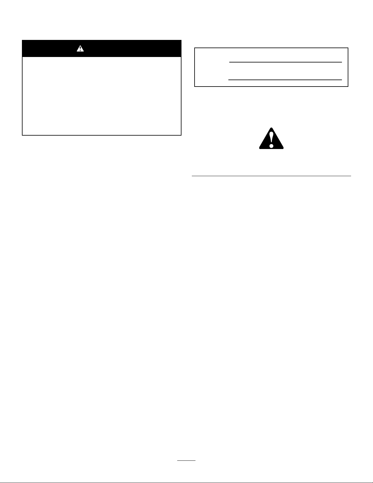
115-7355
1.Warning—toxicgas
inhalationhazard;do
notusethemachine
indoors.
2.Explosionhazard;stopthe
engineandextinguishall
ameswhenfueling.
3.Warning;stoptheengine
andturnofftheignition
beforeleavingthemachine
orfueling.
4.Warning;disconnectthe
sparkplugwireandread
theinstructionsbefore
servicingorperforming
maintenance.
5.Hotsurface;donottouch.
93-9356
1.Entanglementhazard—stayawayfrommovingparts.
93-6085
1.Fast
2.Continuousvariable
setting
3.Slow
93-8064
1.Warning—readtheinstructionsbeforeservicingor
performingmaintenance.
2.Cuttinghazardoffootorhand—stoptheengineandwait
formovingpartstostop.
1.Reeldrive3.Disengage
2.Engage
93-7346
8
Page 9
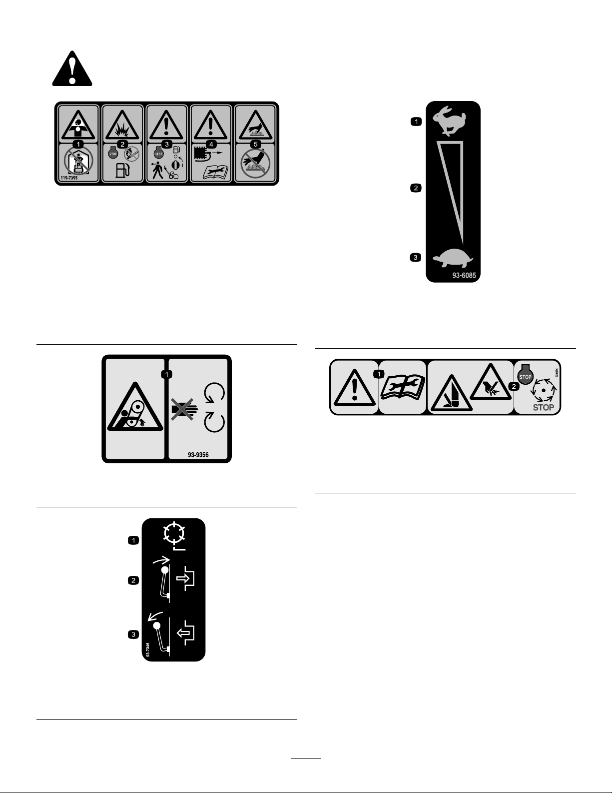
115-1614
1.Warning—readtheOperator'sManual.3.Thrownobjecthazard—keepbystandersasafedistancefrom
2.Warning—donotoperatethemachineunlessyouaretrained.
themachine.
4.Warning—stayawayfrommovingparts;keepallguardsin
place.
115-1720
1.Forward3.Neutral
2.Drivewheel
117–2718
120-2727
1.Brake—toengage,pullthe
levertowardthehandle;
todisengage,releasethe
lever.
2.Parkingbrake—tolock,
pullthelevertowardthe
handle,pressthebutton
inandreleasethelever
againstthelockingbutton;
torelease,pullthelever
towardthehandleuntil
thebuttonreleasesand
releasethelever ..
106-8120
1.Thrownobjecthazard—keepbystandersasafedistance
fromthemachine.
2.Cuttinghazardofhandandfoot—stayawayfrommoving
parts.
9
Page 10
Setup
LooseParts
Usethechartbelowtoverifythatallpartshavebeenshipped.
ProcedureDescription
1
2
3
4
5
6
7
MediaandAdditionalParts
Description
Operator'sManual
EngineOperator'sManual
PartsCatalog
OperatorTrainingMaterial
CerticateofCompliance
Handle1
Cabletie
Kickstandassembly1
Spring
Wheelshaft,right
Wheelshaft,left
Transportwheels(optional)
Nopartsrequired
Grassbasket
High-altitudekit,partnumber117-0073
(acquireseparatelyasneeded)
Qty.
1
1
1
1
1
Readorviewbeforeoperatingthemachine
Qty.
2
1
1
1
2
–
1Installthegrassbasket.
1
Installthehandle.
Installthekickstand.
Installthetransportwheelshafts.
Installthetransportwheels(optional).
Adjustthecuttingunit.
Installthehigh-altitudekit(optional).
Use
Use
Note:Determinetheleftandrightsidesofthemachine
fromthenormaloperatingposition.
1
InstallingandAdjustingthe Handle
Partsneededforthisprocedure:
1Handle
2
Cabletie
InstallingtheHandle
1.Removetheboltsandlocknutssecuringthebottomof
thehandlearmstoeachsideofthemower(Figure2).
Figure2
1.Mountingpins3.Boltandlocknut
2.Handlearms4.Hairpincotterandringpin
2.Removethehairpincottersandringpinssecuringthe
handlearmstotherearoftheframe(Figure2).
3.Insertthehandleendsthroughtheholesinthehandle
armsandaligntheholeswiththemountingpins
(Figure2).
10
Page 11
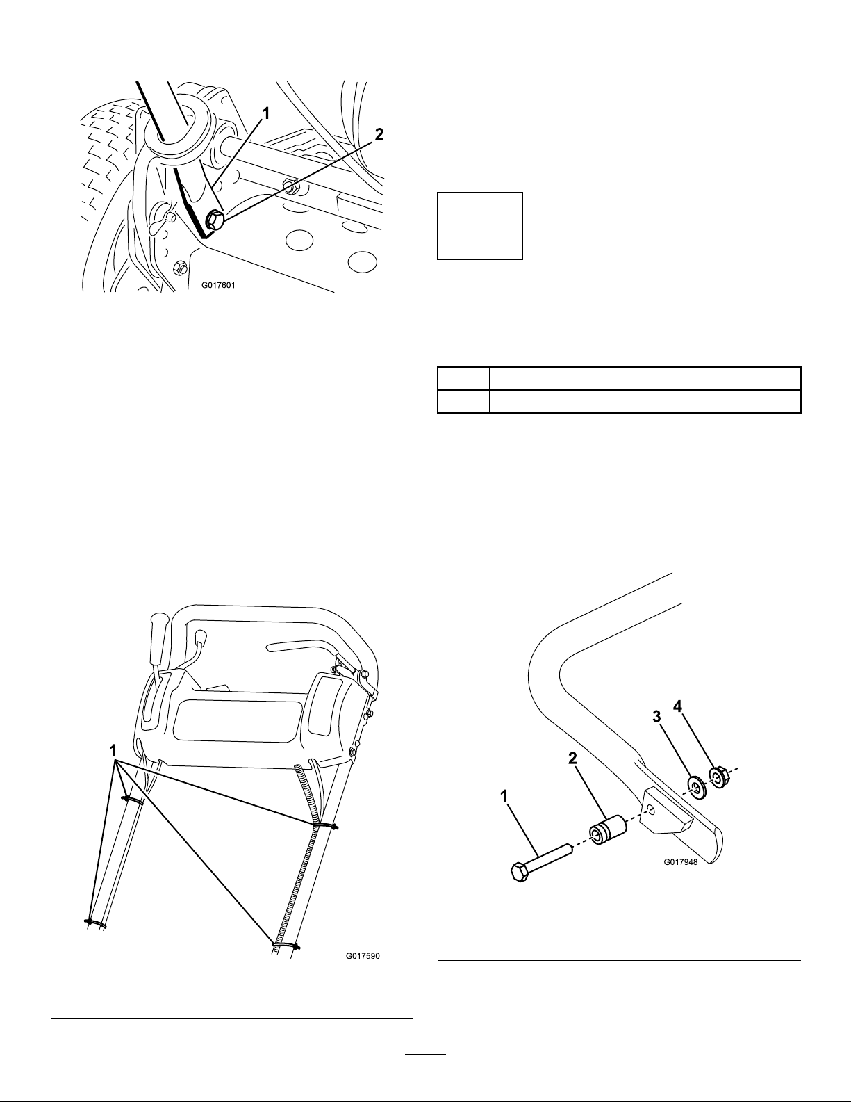
4.Squeezethehandleendsinwardandinstallthemonthe
2
G017601
G017590
1
G017948
1
2
3
4
mountingpins(Figure3).
Figure3
1.Handleend
2.Bolt,washer,andlockwasher
AdjustingtheHandle
1.Removethehairpincottersfromtheringpinsoneach
sideofthemower(Figure2).
2.Whilesupportingthehandle,removetheringpins
fromeachsideandraiseorlowerthehandletothe
desiredoperatingposition(Figure2).
3.Installtheringpinsandhairpincotters.
2
InstallingtheKickstand(For GR800andGR1600)
Partsneededforthisprocedure:
5.Securethehandleendstothemountingpinswiththe
bolts,washers,andlockwashersprovided(Figure3).
6.Securethebottomofthehandlearmstoeachside
ofthemowerwiththeboltsandlocknutspreviously
removed(Figure3).Ensurethatyouinstallthe
bushingsinthehandlearmmountingholes.
7.Securethehandlearmstotherearoftheframewith
thehairpincottersandringpinspreviouslyremoved
(Figure3).
8.Securethecablesandwireharnesstothehandlewith
cableties(Figure4).
1Kickstandassembly
1
Spring
Procedure
Note:Thefastenersareshippedlooselyinstalledonthe
kickstandassembly .
1.OntheGR1600only,connectthespringstudtothe
righthandsideofthekickstand(Figure5)usingthe
bolt,washer,andange-headnutprovided.
1.Cableties
Figure4
1.Bolt3.Washer
2.Springstud
2.Hookthespringintotheholeinthespringbracketand
ontothespringstudwhilealigningthekickstandwith
themountingholesintherearframe(Figure6).
11
Figure5
4.Flange-headnut
Page 12
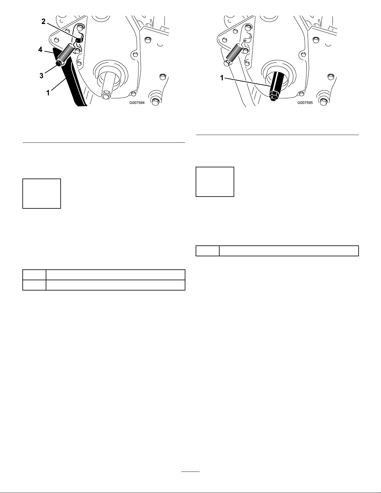
Figure6
Figure7
1.Kickstand
2.Springbracket4.Spring
3.Mountthekickstandtoeachsideoftheframewitha
bolt,lockwasher,spacer,atwasherandlocknut(Figure
6).Positionthespacerinthekickstandmountinghole.
3.Springstud
3
InstallingtheTransportWheel Shafts(ForGR1000and GR1600)
Partsneededforthisprocedure:
1
Wheelshaft,right
1
Wheelshaft,left
Procedure
1.Pushthekickstanddownwithyourfootandpullup
onthehandletosupportthemoweronthekickstand.
1.Rightwheelshaft
4.Torquetheshaftto88to101N-m(65to75ft-lb).
5.Repeatontheleftside.
4
InstallingtheTransport Wheels(Optional)
Partsneededforthisprocedure:
2
Transportwheels(optional)
Procedure
1.Slidethewheelontotheaxle(Figure8).
2.Pivotthewheellockingclipawayfromcenterofthe
wheelallowingittoslidefartherontotheaxle(Figure
8).
2.Apply#242Loctitetothethreadsofthewheelshafts.
3.Threadtherightwheelshaftintothedrivepulleyon
therightsideofthemachine(Figure7).
Note:Therightwheelshafthaslefthandthreads.
12
Page 13

G017591
Figure8
1.Lockingclip
3.Rotatethewheelbackandforthuntilitslides
completelyontotheaxleandthelockingclipissecured
inthegrooveontheaxleshaft.
4.Repeattheprocedureontheoppositesideofthe
machine.
5.Inatethetiresto574to718Pa(12to15psi.).
6
InstallingtheGrassBasket
Partsneededforthisprocedure:
1
Grassbasket
Procedure
Graspthebasketbythetoplipandslideitontothebasket
mountingrods(Figure9).
Figure9
1.Grassbasket
2.Basketmountingrod
5
AdjustingtheCuttingUnit
NoPartsRequired
Procedure
Beforeoperatingthemachine,completethefollowing
adjustments:
•LevelingtheRearDrumtotheReel(page31).
•AdjustingtheBedknifetotheReel(page32).
•AdjustingtheHeightofCut(page33).
•AdjustingtheGrassShieldHeight(page34).
•AdjustingtheCut-OffBar(page34).
RefertotheCuttingUnitMaintenancesectioninMaintenance
forinstructionsonperformingtheseprocedures.
Note:Model04056only—Whencuttinginhigher
heights-of-cut,thebasketmaybeloweredbyremovingeach
basketmountingrodandinstallingeachontheoppositeside
ofthemachine.
7
InstallingtheHigh-AltitudeKit (Optional)
Partsneededforthisprocedure:
High-altitudekit,partnumber117-0073(acquire
1
separatelyasneeded)
Procedure
Ifyouwillbeusingthemachineataltitudesabove1500
m(5000ft),obtainandinstalltheHigh-AltitudeKit,part
number117-0073.
13
Page 14

ProductOverview
1
2
3
4
5
6
7
G017592
G016976
G016977
Controls
Figure11
ParkingBrake
Figure10
1.Tractiondrivelever
2.Throttlecontrol6.Parkingbrake
3.On/offswitch7.Operatorpresencecontrol
4.Hourmeter
5.Servicebrake
(optional)
ThrottleControl
Thethrottlecontrol(Figure10)islocatedontherearright
sideofthecontrolpanel.Theleverconnectstoandoperates
thethrottlelinkagetothecarburetor.SeeSpecications(page
15)forenginespeed.
TractionDriveLever
Thetractiondrivelever(Figure10)islocatedonthefront
rightsideofthecontrolpanel.Ithastwopositions:Neutral
andForward.Pushingtheleverforwardengagesthetraction
drive.
Theparkingbrake(Figure12)islocatedatthebaseofthe
servicebrake.Fullyengagetheservicebrakeandpushthe
parkingbrakeknobtoallowtheservicebraketorestonthe
parkingbrakepin.Engagetheservicebraketoreleasethe
parkingbrake.Youmustreleasethebrakebeforethetraction
driveisengaged.
Figure12
ServiceBrake
Theservicebrake(Figure11)islocatedonthetopleftfront
sideofthecontrolpanel.Youcanusethebraketoslowor
stopthemachine.
On/OffSwitch
Theon/offswitch(Figure10)islocatedonthetopofthe
controlpanel.MovetheswitchtotheOnpositiontostartthe
engineandtheOffpositiontostoptheengine.
OperatorPresenceControl(Optional)
Ifequipped,theoperatorpresencecontrol(Figure10)is
locatedontherearofthehandle.Pushtheoperatorpresence
controlagainstthehandle.Ifequipped,theoperatorpresence
controlmustbeengagedbeforemovingthetractiondrive
leverortheenginewillstop.
14
Page 15

ReelDriveLever
G016978
1
1
g024364
2
RecoilStarter
Thereeldrivelever(Figure13)islocatedontherightfront
cornerofthemachine.Theleverhastwopositions:Engage
andDisengage.Movetheleverforwardtoengagethereelor
rearwardtodisengagethereel.
Figure13
1.Reeldrivelever
ChokeLever
Pulltherecoilstarterhandle(Figure15)tostarttheengine.
Figure15
1.Recoilstarter2.Kickstand
Kickstand
Thekickstand(Figure15)ismountedtotherearofthe
machineandisusedtoraisetherearofthemachinefor
installationorremovalofthetransportwheels.
Thechokelever(Figure14)islocatedontheleftfrontofthe
engine.Theleverhastwopositions:RunandChoke.Move
thelevertotheChokepositionwhenstartingacoldengine.
Aftertheenginestarts,movethelevertotheRunposition.
Figure14
1.Chokelever2.Fuelshut-offvalve
FuelShut-OffValve
Thefuelshut-offvalve(Figure14)islocatedontheleft
frontoftheenginenearthechokelever.Thevalvehastwo
Specications
Width
Height
Lengthwith
basket
Dryweight
(withbasket
andWiehle
roller;without
wheelsor
grooming
reel)
Widthofcut46cm(18
Heightofcut
Clip3.3mm(0.13
EnginespeedLowidle
Model04054Model04055Model04056
84cm(33
inches)
114cm(45
inches)
122cm(48
inches)
97kg(216lb)100kg(220
inches)
1.6mmto
31.8mm
(0.063to1.25
inches)
inches)
–1565±150
RPM,High
idle–3375
±100RPM
91cm(36
inches)
114cm(45
inches)
122cm(48
inches)
lb)
53cm(21
inches)
1.6mmto
31.8mm
(0.063to1.25
inches)
4.3mm(0.17
inch)
Lowidle
–1565±150
RPM,High
idle–3375
±100RPM
104cm(41
inches)
122cm(48
inches)
150cm(59
inches)
105kg(232
lb)
66cm(26
inches)
3.1mmto
31.7mm
(0.125to1.25
inches)
5.8mm(0.23
inch)
Lowidle
–1565±150
RPM,High
idle–3375
±100RPM
positions:ClosedandOpen.Movetheleveruptotheclosed
positionwhenstoringortransportingthemachine.Openthe
valvebeforestartingtheenginebyrotatingtheleverdown.
15
Page 16

Attachments/Accessories
AselectionofToroapprovedattachmentsandaccessoriesis
availableforusewiththemachinetoenhanceandexpand
itscapabilities.ContactyourAuthorizedServiceDealeror
Distributororgotowww .Toro.comforalistofallapproved
attachmentsandaccessories.
Operation
Note:Determinetheleftandrightsidesofthemachine
fromthenormaloperatingposition.
ThinkSafetyFirst
Pleasecarefullyreadallofthesafetyinstructionsanddecals
inthesafetysection.Knowingthisinformationcouldhelp
youorbystandersavoidinjury.
CheckingtheEngineOilLevel
Checktheengineoillevelbeforeeachuseorevery8operating
hours,refertoCheckingtheEngineOilLevel(page23)in
EngineMaintenance(page23).
FillingtheFuelTank
Note:Thefueltankcapacityis2.7liters(2-3/4quarts).
•Forbestresults,useonlyclean,fresh(lessthan30days
old),unleadedgasolinewithanoctaneratingof87or
higher((R+M)/2ratingmethod).
•Ethanol:Gasolinewithupto10%ethanol(gasohol)
or15%MTBE(methyltertiarybutylether)byvolume
isacceptable.EthanolandMTBEarenotthesame.
Gasolinewith15%ethanol(E15)byvolumeisnot
approvedforuse.Neverusegasolinethatcontains
morethan10%ethanolbyvolume,suchasE15
(contains15%ethanol),E20(contains20%ethanol),or
E85(containsupto85%ethanol).Usingunapproved
gasolinemaycauseperformanceproblemsand/orengine
damagewhichmaynotbecoveredunderwarranty.
•Donotusegasolinecontainingmethanol.
•Donotstorefueleitherinthefueltankorfuelcontainers
overthewinterunlessafuelstabilizerisused.
•Donotaddoiltogasoline.
16
Page 17

DANGER
G017594
1
WARNING
Incertainconditions,gasolineisextremely
ammableandhighlyexplosive.Areorexplosion
fromgasolinecanburnyouandothersandcan
damageproperty.
•Fillthefueltankoutdoors,inanopenarea,
whentheengineiscold.Wipeupanygasoline
thatspills.
•Neverllthefueltankinsideanenclosedtrailer.
•Donotllthefueltankcompletelyfull.Add
gasolinetothefueltankuntilthelevelis6to13
mm(1/4to1/2inch)belowthebottomofthe
llerneck.Thisemptyspaceinthetankallows
gasolinetoexpand.
•Neversmokewhenhandlinggasoline,andstay
awayfromanopenameorwheregasoline
fumesmaybeignitedbyaspark.
•Storegasolineinanapprovedcontainerand
keepitoutofthereachofchildren.Neverbuy
morethana30-daysupplyofgasoline.
•Donotoperatewithoutentireexhaustsystemin
placeandinproperworkingcondition.
Gasolineisharmfulorfatalifswallowed.Long-term
exposuretovaporscancauseseriousinjuryand
illness.
•Avoidprolongedbreathingofvapors.
•Keepfaceawayfromnozzleandgastankor
conditionerbottleopening.
•Avoidcontactwithskin;washoffspillagewith
soapandwater.
1.Cleanaroundthefueltankcapandremovethecap
fromthetank(Figure16).
Figure16
DANGER
Incertainconditionsduringfueling,static
electricitycanbereleasedcausingasparkwhich
canignitethegasolinevapors.Areorexplosion
fromgasolinecanburnyouandothersandcan
damageproperty.
•Alwaysplacegasolinecontainersontheground
awayfromyourvehiclebeforelling.
•Donotllgasolinecontainersinsideavehicleor
onatruckortrailerbedbecauseinteriorcarpets
orplastictruckbedlinersmayinsulatethe
containerandslowthelossofanystaticcharge.
•Whenpractical,removegas-poweredequipment
fromthetruckortrailerandrefueltheequipment
withitswheelsontheground.
•Ifthisisnotpossible,thenrefuelsuch
equipmentonatruckortrailerfromaportable
container,ratherthanfromagasolinedispenser
nozzle.
•Ifagasolinedispensernozzlemustbeused,
keepthenozzleincontactwiththerimofthe
fueltankorcontaineropeningatalltimesuntil
fuelingiscomplete.
1.Fueltankcap
2.Usingunleadedgasoline,llthefueltanknohigher
thanthebottomofthelterscreen.Thisspaceallows
thegasolinetoexpand.Donotllthefueltank
completelyfull.
3.Installfueltankcapandwipeupanyspilledgasoline.
Break-inPeriod
RefertotheEngineManualsuppliedwiththemachineforoil
changeandmaintenanceproceduresrecommendedduring
thebreak-inperiod.
Only8hoursofmowingoperationisrequiredforthebreak-in
period.
Sincethersthoursofoperationarecriticaltofuture
dependabilityofthemachine,monitoritsfunctionsand
performancecloselysothatminordifculties,whichcould
leadtomajorproblems,arenotedandcanbecorrected.
Inspectthemachinefrequentlyduringbreak-inforsignsof
oilleakage,loosefasteners,oranyothermalfunction.
Toensureoptimumperformanceofthebrakesystem,burnish
(break-in)thebrakesbeforeusingthemachine.Toburnish
thebrakes,rmlyapplythebrakesanddrivethemachineat
mowingspeeduntilthebrakesarehot,asindicatedbytheir
smell.Anadjustmenttothebrakesmayberequiredafter
17
Page 18

break-in;refertoAdjustingtheService/ParkingBrake(page
26).
CheckingtheInterlockSwitch Operation
CAUTION
Ifsafetyinterlockswitchesaredisconnectedor
damagedthemachinecouldoperateunexpectedly
causingpersonalinjury.
•Donottamperwiththeinterlockswitches.
•Checktheoperationoftheinterlockswitches
dailyandreplaceanydamagedswitchesbefore
operatingthemachine.
1.Pushthekickstanddownwithyourfootandpullup
andbackonthehandletoraisethewheelsoffofthe
ground.
2.PlacethetractionleverintotheEngagepositionand
theenginecontrolsinthestartingposition.
3.Attempttostarttheengine.
Theengineshouldnotstart.Iftheenginestarts,the
interlockswitchneedsservice.Correcttheproblem
beforeoperating.RefertoServicingtheInterlock
Switch(page26).
4.Carefullyliftuponthehandletoreleasethekickstand.
DailyAdjustmentsofthe
Figure17
Note:Ifexcessivecontact/reeldragisevidentitwill
beeithernecessarytobacklap,refacethefrontofthe
bedknife,orregrindthecuttingunittoachievethe
sharpedgesneededforprecisioncutting(Refertothe
ToroManualforSharpeningReelandRotaryMowers,
FormNo.09168SL).
Important:Lightcontactispreferredatalltimes.If
youdonotmaintainlightcontact,thebedknifeandreel
edgeswillnotsufcientlyself-sharpenandwilldullafter
aperiodofoperation.Ifyoumaintainexcessivecontact,
thebedknifeandreelwillwearquicker,wearunevenly,
andthequalityofcutmaybeadverselyaffected.
Note:Afterextendedrunning,aridgewilleventually
developatbothendsofthebedknife.Roundofforlethese
notchesushwiththecuttingedgeofthebedknifetoensure
smoothoperation.
CuttingUnit
Priortomowingeachday,orasrequired,checkeachcutting
unittoverifyproperbedknife-to-reelcontact.Thismustbe
performedeventhoughqualityofcutisacceptable.
1.Lowerthecuttingunitsontoahardsurface,shutoff
theengine,andremovetheignitionkey .
2.Slowlyrotatethereelinareversedirection,listening
forreel-to-bedknifecontact.
Note:Theadjustmentknobshavedetents
correspondingto0.018mm(0.0007inch)bedknife
movementforeachindexedposition.Referto
AdjustingtheBedknifetotheReel.
3.Testthecuttingperformancebyinsertingalongstrip
ofcuttingperformancepaper(T oropartnumber
125-5610)betweenreelandbedknife,perpendicular
tothebedknife(Figure17).Slowlyrotatethereel
forward;itshouldcutthepaper.
StartingandStoppingthe Engine
Note:Forillustrationsanddescriptionsofthecontrols
referencedinthissection,refertotheControls(page14)
sectioninProductOverview(page14).
StartingtheEngine
Note:Ensurethatthesparkplugwireisinstalledonthe
sparkplug.
1.Ensurethatthetractionandreeldriveleversareinthe
Disengagedposition.
Note:Theenginewillnotstartifthetractionleveris
intheEngagedposition.
2.Openthefuelshut-offvalveontheengine.
3.Movetheon/offswitchtotheOnposition.
4.MovethethrottlecontroltotheFastposition.
18
Page 19

5.MovethechokeleverhalfwaybetweentheOnandOff
positionswhenstartingacoldengine.Thechokemay
notberequiredwhenstartingawarmengine.
6.Pulltherecoilstarterhandleoutuntilpositive
engagementresults,thenpullitvigorouslytostartthe
engine.
Important:Donotpullrecoilropetoitslimitor
letgoofstarterhandlewhenropeispulledout
becauseropemaybreakorrecoilassemblymay
bedamaged.
7.MovethechoketotheOffpositionastheengine
warmsup.
3.Slidethewheelsoffoftheshafts.
4.Movetheunitoffofthekickstand.
Mowing
Properuseofthemachineprovidesthesmoothestturf
cuttingavailable.ReferalsotoOperatingTips(page19)for
fundamentalsuggestionstoobtaintheutmostperformance
fromyourmower.
Important:Excessiveoperationofthecuttingunitwith
theabsenceofgrassclippings(lubricant)candamage
thecuttingunit.
StoppingtheEngine
1.Movethetractionandreeldrivecontrolstothe
Disengagedposition,thethrottlecontroltotheSlow
position,andtheOn/OffswitchtotheOffposition.
2.Pullthesparkplugwireoffofthesparkplugtoprevent
thepossibilityofaccidentalstartingbeforestoringthe
machine.
3.Closethefuelshut-offvalvebeforestoringor
transportingthemowerinavehicle.
DrivingtheMachinein Transport
1.Ifthemachineisequippedwiththeoptionaltransport
wheels,pushthekickstanddownwithyourfootand
pulluponthehandletoraisetherearofthemower
andinstallthetransportwheels.
2.Toreleasethekickstand,pulluponthehandle,push
themowerforward,andthenlowertherearofthe
mowerontothetransportwheels.
3.Ensurethatthetractionandreeldrivecontrolsarein
theDisengagedpositionandstarttheengine.
4.SetthethrottlecontroltoSlow ,raisethefrontofthe
machineupslightly ,graduallyengagethetractiondrive
andslowlyincreasetheenginespeed.
5.Adjustthethrottletooperatethemoweratthedesired
groundspeedandtransportthemowertothedesired
destination.
6.ReturnthetractioncontrollevertotheDisengage
position,thethrottletotheSlowposition,andstop
theengine.
1.Starttheengine,setthethrottleatareducedspeed,
pushdownonthehandletoraisethecuttingunit,
movethetractionlevertotheEngagedposition,and
transportthemowerontothecollarofthegreen.
2.MovethetractionlevertotheDisengagedpositionand
movethereeldrivelevertotheEngagedposition.
3.MovethetractionlevertotheEngagedposition,
increasethethrottlespeeduntilthemoweristraveling
atthedesiredgroundspeed,drivethemowerontothe
green,lowerthefrontofthemower,andcommence
operation.
4.Whennishedmowing,driveoffofthegreen,move
thetractioncontrollevertotheDisengageposition,
stoptheengineandpushthereeldriveleverintothe
Disengageposition.
5.Emptythegrassbasketofclippings,installthegrass
basket,andcommencetransportoperation.
OperatingTips
BeforeMowing
•Ensurethatthemoweriscarefullyadjustedandisset
evenlyonbothsidesofthereel.Impropermower
adjustmentismagniedmanytimesoverinthe
appearanceoftheclippedturf.
•Removeallforeignobjectsfromtheturfpriortomowing.
•Ensurethateveryone,especiallychildrenandpets,are
clearoftheworkarea.
MowingTechniques
PreparingtoMow
1.Ifthemachineisequippedwiththeoptionaltransport
wheels,pushthekickstanddownwithyourfootand
pullupandbackonthehandletoraisethewheelsoff
oftheground.
2.Pushthelockingclipsonthewheelsoutofthegrooves
intheshafts.
•Mowagreeninastraightbackandforthdirection,across
thegreen.
•Avoidcircularmowingorturningthemoweronagreen
becausescufngmayoccur.Turnthemoweroffofthe
greenbyraisingthecuttingreel(pushingthehandle
down)andturningonthetractiondrum.
•Mowatanormalwalkingpace.Fastspeedsavesvery
littletimeandwillresultinaninferiormowingjob.
19
Page 20

Maintenance
Note:Determinetheleftandrightsidesofthemachinefromthenormaloperatingposition.
RecommendedMaintenanceSchedule(s)
MaintenanceService
Interval
Aftertherst20hours
Beforeeachuseordaily
Every25hours
Every50hours
Every100hours
Every500hours
Every1,000hours
Important:Refertoyour
MaintenanceProcedure
•Changetheengineoil.
•Cleanthefuellterandcup.
•Checktheinterlockswitchoperation.
•Checktheengineoillevel.
•Greasethemachine.(Greasethettingsimmediatelyaftereverywashing
regardlessoftheintervallisted.)
•Changetheengineoil.(Morefrequentlyindustyordirtyconditions)
•Cleanandoiltheaircleanerfoamelement.(Moreoftenindirtyordustyconditions)
•Replacethepaperairlterelement.(Moreoftenindirtyordustyconditions)
•Checkthesparkplug.
•Cleanthefuellterandcup.
•Checkintakeandexhaustvalves.Adjustasnecessary.
•Cleanthecarburetor.
•replacethefuelline.
•Checkthetransmissiondrivebelts.
•Checkthetransmissionbearings.
Engine Operator's Man ual
foradditionalmaintenanceprocedures.
20
Page 21

DailyMaintenanceChecklist
Important:Duplicatethispageforroutineuse.
Maintenance
CheckItem
Checkthe
safetyinterlock
operation.
Checkthe
parkingbrake
operation.
Checkthefuel
level.
Checktheengine
oillevel.
Checktheair
lter.
Cleantheengine
coolingns.
Checkfor
unusualengine
noises.
Checkfor
unusual
operatingnoises.
Checkthe
reel-to-bedknife
adjustment.
Checkthe
height-of-cut
adjustment.
Greaseall
ttings.
Touchup
damagedpaint.
Fortheweekof:
Mon.Tues.Wed.Thurs.Fri.
Sat.Sun.
NotationforAreasofConcern
Inspectionperformedby:
ItemDate
Information
21
Page 22

Lubrication
G016993
G016981
G016982
GreasingtheMachine
ServiceInterval:Every25hours
Lubricatethe13greasettingsonthemowerusingaNo.2
multipurposelithiumbasegrease.Ahandoperatedgrease
gunisrecommendedforbestresults.
Thegreasettinglocationsareasfollows:
•2onthefrontroller(Figure18)
•2onthereelbearings(Figure18)
•2onthedrumaxles(Figure19)
•3onthedifferential(Figure19)
•2onthereelcountershaftbearings(Figure20)
•2onthebeltidlerpivots(Figure21).
1.Wipeeachgreasettingwithacleanrag.
2.Pumpgreaseintoeachttinguntilitbeginstoget
difculttopumpthegun.
Important:Donotapplytoomuchpressureor
greasesealswillbecomepermanentlydamaged.
3.Wipeoffanyexcessgrease.
Figure20
Figure21
Figure18
Figure19
22
Page 23

EngineMaintenance
G016983
1
ServicingtheEngineOil
ServiceInterval:Aftertherst20hours—Changethe
engineoil.
Beforeeachuseordaily—Checktheengineoillevel.
Every50hours—Changetheengineoil.(More
frequentlyindustyordirtyconditions)
Thecrankcasemustbelledwithapproximately21uid
ouncesofproperviscosityoilbeforestaring.Theengine
usesanyhigh-qualityoilhavingtheAmericanPetroleum
Institute-APl-“serviceclassication"SF,SG,SHorSJ.Oil
viscosity-weight-mustbeselectedaccordingtoambient
temperature.Figure22illustratesthetemperature/viscosity
recommendations.
Figure23
1.Oillevelgauge
2.Removetheoillevelgaugebyrotatingit
counterclockwise.
3.Wipetheoillevelgaugecleanandinsertitintotheller
port.Donotscrewitintotheport.
2.Drainplug
Figure22
Note:Usingmulti-gradeoils(5W-20,10W -30,and10W -40)
willincreaseoilconsumption.Checktheoillevelmore
frequentlywhenusingthem.
CheckingtheEngineOilLevel
1.Positionthemowersothattheengineislevelandclean
aroundtheoillevelgauge(Figure23).
4.Removethegaugeandchecktheleveloftheoil.
5.Ifthelevelislow,addonlyenoughoiltoraisethelevel
untilitisbetweenthehatchmarksonthegauge(Figure
24).Donotoverll.
Figure24
1.Hatchmarks
6.Installtheoillevelgaugeandwipeupanyspilledoil.
ChangingtheEngineOil
1.Startandruntheengineforafewminutestowarm
theengineoil.
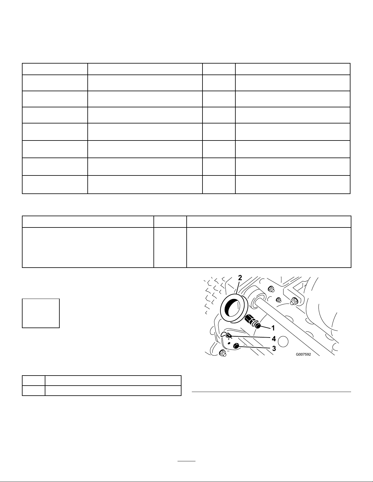
2.Placeadrainpanattherearofmachine,underthe
drainplug(Figure23).
3.Removethedrainplug.
4.Pushdownonthehandletotipthemowerandthe
enginebackward,allowingmoreoiltorunintothe
drainpan.
23
Page 24

5.Installthedrainplugandrellthecrankcasewiththe
1
G016984
G016985
1
2
3
4
5
G016986
1
properoil;refertoCheckingtheEngineOilLevel
(page16).
ServicingtheAirCleaner
ServiceInterval:Every50hours—Cleanandoiltheair
cleanerfoamelement.(Moreoftenin
dirtyordustyconditions)
Every100hours—Replacethepaperairlterelement.
(Moreoftenindirtyordustyconditions)
Important:Servicetheaircleanermoreoftenindirty
ordustyconditions
1.Makesurethewireisoffofthesparkplug.
2.Removethewingnutsecuringtheaircleanercoverand
removethecover(Figure25).
Figure26
1.Wingnut4.Foamelement
2.Aircleanercover5.Paperelement
3.Plasticwingnut
5.Checktheconditionofthepaperelement.Cleanitby
gentlytappingorreplaceitasrequired.
Important:Donotusecompressedairtoclean
thepaperelement.
6.Installthefoamelement,paperelement,andaircleaner
cover.
Figure25
1.Aircleanercover
Important:Donotoperatetheenginewithoutthe
aircleanerelementbecauseextremeenginewear
anddamagewilllikelyresult.
3.Cleanthecoverthoroughly.
4.Ifthefoamelementisdirty ,removeitfromthepaper
element(Figure26)andcleanitthoroughly,asfollows:
A.Washthefoamelementinasolutionofliquid
soapandwarmwater.Squeezeittoremovedirt,
ReplacingtheSparkPlug
ServiceInterval:Every100hours
UseanNGKBR6HSsparkplugorequivalent.Thecorrect
airgapis0.6-0.7mm(0.024-0.028inches).
butdonottwistitbecausethefoammaytear.
1.Pullthemoldedwireoffofthesparkplug(Figure27).
B.Drythefoamelementbywrappingitinaclean
rag.Squeezetheragandfoamelementtodryit,
butdonottwistit.
C.Saturatethefoamelementwithcleanengineoil.
Squeezetheelementtoremoveexcessoilandto
distributetheoilthoroughly.Anoildampelement
isdesirable.
1.Sparkplugwire
Figure27
24
Page 25

2.Cleanaroundthesparkplugandremoveitfromthe
4
G016987
G016988
1
2
cylinderhead.
FuelSystem
Important:Replaceacracked,fouled,ordirty
sparkplug.Donotsandblast,scrape,orclean
electrodesbecauseenginedamagecouldresult
fromgritenteringthecylinder.
3.Ensurethattheairgapiscorrect(Figure28).
Figure28
4.Installthecorrectlygappedsparkplugandtightenitto
23N-m(17ft.-lb).
5.Installthesparkplugwireonthesparkplug.
Maintenance
CleaningtheFuelFilter
ServiceInterval:Aftertherst20hours
Every100hours
1.Closethefuelshut–offvalveandunscrewthebowl
fromthelterbody(Figure29).
Figure29
1.Bowl
2.Cleanthebowlandlterincleangasolineandinstallit.
2.Fuelshut–offvalve
25
Page 26

ElectricalSystem
G016989
1
2
3
4
G016990
Maintenance
BrakeMaintenance
AdjustingtheService/Parking
ServicingtheInterlockSwitch
Usethefollowingprocedureiftheswitchneedsadjustment
orreplacement.
1.Makesuretheengineisoffandthetractionleveris
disengagedandrestingagainsttheneutralstop(Figure
30).
Brake
Iftheservice/parkingbrakeslipswhenoperated,an
adjustmentisrequired.
1.Engagetheservicebrake,pushinontheparkingbrake
knobandallowtheservicebraketorestontheparking
brakepin(Figure31)
Figure30
1.Tractionlever3.Interlockswitch
2.Neutralstop
2.Loosentheinterlockswitchmountingfasteners(Figure
30).
3.Placea.032"thickshimbetweenthetractionleverand
theinterlockswitch(Figure30).
4.Tightentheinterlockswitchmountingfasteners.
Recheckthegap.Thetractionlevermustnotcontact
theswitch.
5.Engagethetractionleverandverifythattheswitch
losescontinuity.Replaceifrequired.
4..032"Gap
Figure31
2.Usingaspringscale,pressrearwardontheservice
brakelever(Figure32).Theparkingbrakeshould
releasewhenaforceof13.5to18kg(30to40lbs)is
attained.Iftheparkingbrakereleasesbefore13.5to18
kg(30to40lbs)offorceisattained,anadjustmentto
thebrakecableisrequired.Proceedtostep3.
26
Page 27

G016991
1
2
Figure34
Figure32
1.Rearpressureonservicebrakelever
3.LoosentheretainersecuringtheV-beltcoverandpivot
thecoveropen(Figure33).
Figure33
1.V–beltcover2.Retainer
1.Service/Parkingbrake
cable
2.Frontjamnut
5.Closethecoverandsecuretheretainer.
4.Toadjustthebrakecabletension,proceedasfollows.
•Todecreasethecabletension,loosenthefront
cablejamnutandtightentherearjamnut(Figure
34).Repeatsteps1and2andreadjustifrequired.
•Toincreasethecabletension,tightenthefront
cablejamnutandloosentherearjamnut(Figure
34).Repeatsteps1and2andreadjustifrequired.
Note:Theadjustmentcanbeperformedonthe
cableatthejamnutbracketsbythecontrolpanel
oratthebracketatthebaseoftheengine.
27
Page 28

BeltMaintenance
AdjustingtheBelts
Ensurethatthebeltsareproperlytensionedtoensureproper
operationofthemachineandunnecessarywear.Checkthe
beltsfrequently.
5.Whilemaintainingaslightgapbetweenthecoverseal
andthesideplate,installeachmountingboltuntilthe
threadsengageintheinsert.Thegapallowsvisual
alignmentoftheboltstothethreadedinserts.
6.Afterallboltsareinstalled,tightenthemuntilthe
stand-offsinsidethecovercontactthesideplate.Do
notovertighten.
AdjustingtheReelDriveBelt
1.Removethebeltcovermountingfastenersandbelt
covertoexposethebelt(Figure35).
Figure35
1.Beltcover
2.Checkthetensionbypressingthebeltatmidspanof
thepulleys(Figure36)with18–22N(4to5lbs)of
force.Thebeltshoulddeect6mm(1/4inch).
AdjustingtheTractionDriveBelt
1.Removethebeltcovermountingfastenersandthebelt
covertoexposethebelt(Figure37).
Figure37
1.Tractiondrivebeltcover
2.Checkthetensionbypressingthebeltatmidspanof
thepulleys(Figure38)with18–22N(4to5lbs)of
force.Thebeltshoulddeect6mm(1/4inch).
Figure36
1.Reeldrivebelt2.Idlerpulley
3.Completethefollowingtoadjustthebelttension:
A.Loosentheidlerpulleymountingnutandpivot
theidlerpulleyclockwiseagainstthebacksideof
thebeltuntilyouattainthedesiredbelttension
(Figure36).
Important:Donotovertensionthebelt.
B.Tightenthenuttolocktheadjustment.
4.Installthebeltcoverbyplacingitinposition.
Figure38
1.Tractiondrivebelt2.Idlerpulley
3.Completethefollowingtoadjustthebelttension:
A.Loosentheidlerpulleymountingnutandpivot
theidlerpulleyclockwiseagainstthebacksideof
thebeltuntilthedesiredbelttensionisattained
(Figure38).
Important:Donotovertensionthebelt.
B.Tightenthenuttolocktheadjustment.
4.Installthebeltcoverbyplacingitinposition.
28
Page 29

5.Whilemaintainingaslightgapbetweenthecoverseal
G016991
1
2
G016992
1
2
3
4
andthesideplate,installeachmountingboltuntilthe
threadsengageintheinsert.Thegapallowsvisual
alignmentoftheboltstothethreadedinserts.
6.Afterallboltsareinstalled,tightenthemuntilthe
stand-offsinsidethecovercontactthesideplate.Do
notovertighten.
AdjustingtheDifferentialBelt
1.Removetheboltssecuringthefrontandrearsections
ofthedifferentialcovertothedifferentialhousingand
slidethecoversectionsawaytoexposethebelt.
2.Checkthetensionbypressingthebeltatmidspan
ofthepulleys(Figure39)with22–26N(5to6lb)of
force.Thebeltshoulddeect6mm(1/4inch).
2.LoosentheretainersecuringtheV-beltcoverandpivot
thecoveropen(Figure40).
Figure40
1.V-beltcover2.Retainer
3.Toincreasebelttension,loosentheenginemounting
boltsandmovetheenginebackwardsintheslots.
Important:Donotovertensionthebelt.
4.Tightenthemountingbolts.
Note:Thedistancebetweenthecentersofthedriver
andthedrivenpulleysshouldbeapproximately12.85
cm(5.06inches)afternewV -beltsareinstalled.
5.AftertensioningtheprimaryV -belts,checkthe
alignmentoftheengineoutputshaftpulleyandthe
countershaftpulleywithastraightedge.
1.Differentialbelt
Figure39
2.Idlerpulley
6.Ifthepulleysaremisaligned,loosenthescrewssecuring
3.Completethefollowingtoadjustthebelttension:
A.Loosentheidlerpulleymountingnutandpivot
theidlerpulleyclockwiseagainstthebacksideof
theenginemountingbasetothemowerframeand
slidetheenginefromsidetosideuntilthepulleysare
alignedwithin0.07cm(0.030inch).
thebeltuntilthedesiredbelttensionisattained
(Figure39).
Important:Donotovertensionthebelt.
B.Tightenthenuttolocktheadjustment.
4.Installthebeltcoverbyplacingitinposition.
5.Whilemaintainingaslightgapbetweenthecoverseal
andthesideplate,installeachmountingboltuntilthe
threadsengageintheinsert.Thegapallowsvisual
alignmentoftheboltstothethreadedinserts.
6.Afterallboltsareinstalled,tightenthemuntilthe
stand-offsinsidethecovercontactthesideplate.Do
notovertighten.
AdjustingthePrimaryV-Belts
1.ToadjustthebelttensiononprimaryV -belts,rst
checktheadjustmentofthetractioncontrol.Referto
AdjustingtheTractionControl(page31).Ifyouare
unabletoattainthe18–22N(4to5lb)forcerequiredin
adjustingthetractioncontrol,proceedtothenextstep.
Figure41
1.Locknut3.Idlerpulley
2.Beltguide4.Idlerarm
7.Tightenthemountingscrewsandcheckthealignment.
29
Page 30

8.Topushorpullthemachineeasierwithoutstarting
theengine,adjustthebeltguide(Figure41,inset)as
follows:
A.Engagetheclutch.
B.Loosenthelocknutsecuringtheidlerpulleyand
beltguidetotheidlerarm.
C.Rotatethebeltguideclockwiseuntilagapof
approximately0.15cm(0.06inch)isobtained
betweentheguidengerandthebacksideofthe
drivebelts.
D.Tightenthelocknutsecuringtheidlerpulleyand
beltguidetotheidlerarm.
9.Closethecoverandsecuretheretainer.
ReplacingtheDifferentialBelt
1.Removetheboltssecuringthetractiondriveandreel
drivebeltcoverstotherightsideplateandremovethe
beltcovers.
2.Loosentheidlerpulleymountingnutoneachidler
pulleyandpivoteachidlerpulleycounterclockwise
awayfromthebacksideofeachbelttoreleasethebelt
tension.
3.Removethebelts.
4.Removetheboltssecuringthefrontandrearsections
ofthedifferentialcovertothedifferentialhousingand
slidethecoversectionsawaytoexposethebelt(Figure
42).
8.Removethe2boltsandlocknutssecuringtherightrear
bearinghousingtothesideplate(Figure42).
9.Rotatethehousing180°sothebottomofthehousing
pointsupward.Removetheoldbelt.
10.Slidethenewbeltovertherotatedhousingcovers,the
differentialcoversections,andontothedifferential
pulleys.
11.Ensurethattheidlerpulleyispositionedagainstthe
backsideofthebelt.
12.Rotatebothhousingsbackintotheuprightposition
andsecurethemtothesideplatewiththeboltsand
nutspreviouslyremoved.
13.Adjustthedifferentialbelttension;refertoAdjusting
theDifferentialBelt(page29).
14.Adjustthebelttensiononthetractiondriveandreel
drivebelts;refertoAdjustingtheTractionDriveBelt
(page28),andAdjustingtheReelDriveBelt(page28).
15.Installthedifferential,tractiondrive,andreeldrive
covers.
Figure42
1.Differentialcoversections
2.Frontclutchhousing
3.Rightrearbearinghousing
5.Loosentheidlerpulleymountingnutonthedifferential
idlerpulleyandpivottheidlerpulleycounterclockwise
awayfromthebacksideofthebelttoreleasethebelt
tension.
6.Removethe2boltsandlocknutssecuringthefront
clutchhousingtothesideplate(Figure42).
7.Rotatethehousing180°sothebottomofthehousing
pointsupward.
30
Page 31

ControlsSystem
Maintenance
CuttingUnitMaintenance
LevelingtheRearDrumtothe
AdjustingtheTractionControl
Ifthetractioncontroldoesnotengageoritslipsduring
operation,anadjustmentisrequired.
1.MovethetractioncontroltotheDisengagedposition.
2.LoosentheretainersecuringtheV-beltcoverandpivot
thecoveropen(Figure40).
3.Toincreasethecabletension,loosenthefrontcable
jamnutandtightenthebackcablejamnut(Figure
43)untilaforceof3to4kg(7to9lbs)isrequiredto
engagethetractioncontrol.Measuretheforceatthe
controlknob.
Reel
1.Positionthemachineonaat,levelsurface,preferably
aprecisionsteelworkplate.
2.Placea0.6x2.5cm(1/4x1inch)atsteelstrip,
approximately73.6cm(29inches)long,underthereel
bladesandagainstthefrontedgeofthebedknifeto
preventthebedbarfromrestingontheworksurface.
3.Raisethefrontrollersoonlythereardrumandreelare
onthesurface.
4.Firmlypressdownonthemachineabovethereelso
allreelbladescontactthesteelstrip.
5.Whilepressingdownonthereel,slideafeelergauge
underoneendofthedrum,thenchecktheotherend
ofthedrum.
Ifthereisagapbetweenthedrumandtheworksurface,
greaterthan.025cm(0.010inch),oneitherend,adjust
thedrum(proceedtostep6).Ifthegapislessthan
.025cm(0.010inch)noadjustmentisrequired.
6.Removetherearbeltcoverfromtherightsideofthe
machine(Figure44).
Figure43
1.Tractioncable2.Frontjamnut
4.Tightenthefrontcablejamnut.
5.Closethecoverandsecuretheretainer.
6.Checkthetractioncontroloperation.
Figure44
1.Tractiondrivebeltcover
7.Rotatethedrivenpulleyuntiltheholesalignwiththe4
rollerbearingangescrews(Figure45).
31
Page 32

Figure45
g026076
1
2
1.Drivenpulley3.IdlerPulley
2.4holes
Figure46
8.Loosenthe4rollerbearingscrewsandthescrew
securingtheidlerpulley.
9.Raiseorlowertherightsideoftherollerassemblyuntil
thegapislessthan.025cm(0.010inch).
10.Tightentherollerbearingscrews.
11.Adjustthebelttensionandtightentheidlerpulley
mountingscrew(Figure45).
AdjustingtheBedknifetothe Reel
Note:Usethisprocedureaftergrinding,backlapping,or
disassembly.Itisnotintendedasadailyadjustment.
1.Positionthecuttingunitonaat,levelworksurface.
2.Tiltthemowerbackonthehandletoexposethe
bedknifeandreel.
Note:Donottiltthemachinebackfurtherthan60
degreestopreventfuelleakage.
3.Rotatethereelsothatabladecrossesthebedknifeedge
betweentherstandsecondbedknifescrewheadson
therightsideofthecuttingunit.
4.Putanidentifyingmarkonthebladewhereit
crossesthebedknifeedge;thiswillmakesubsequent
adjustmentseasier.
1.Bedbaradjustingscrew2.Nut
7.Fortheleftsideofthecuttingunit,slowlyrotatethe
reelsothattheclosestbladecrossesthebedknifeedge
betweentherstandsecondscrewheads.
8.Repeatsteps4through6fortheleftsideofthecutting
unitandleftbedbaradjustingscrew.
9.Repeatsteps5and6untillightdragisachievedon
boththerightandleftsidesofthecuttingunitutilizing
thesamecontactpoints.
Thebedknifeisnowparalleltothereel.
10.Toobtainlightcontactbetweenthereelandbedknife,
turneachbedbaradjustingscrewclockwise3clicks.
Note:Eachclickturnedonthebedbaradjusting
screwmovesthebedknife0.018mm(0.0007inches).
Clockwiserotationmovesthebedknifeedgecloser
tothereelandcounterclockwiserotationmovethe
bedknifeedgeawayfromthereel.Donotovertighten
theadjustingscrews.
11.Testthecuttingperformancebyinsertingalongstrip
ofcuttingperformancepaper(T oropartnumber
125-5610)betweenthereelandbedknife,perpendicular
tothebedknife(Figure47).Slowlyrotatethereel
forward;itshouldcutpaper
5.Insertthe0.05mm(0.002inch)shimbetweenthe
markedbladeandthebedknifeedgeatthepointwhere
themarkedbladecrossesthebedknifeedge.
6.Turntherightbedbaradjustingscrewuntilyoufeel
lightpressure(i.e.drag)ontheshimbyslidingit
side-to-side.Removetheshim.
32
Page 33

Figure49
Figure47
Note:Ifexcessivecontact/reeldragisevidentitwill
beeithernecessarytobacklap,refacethefrontofthe
bedknife,orregrindthecuttingunittoachievethe
sharpedgesneededforprecisioncutting(Refertothe
ToroManualforSharpeningReelandRotaryMowers,
FormNo.09168SL).
AdjustingtheHeightofCut
1.Verifythattherearrollerislevelandthatthebedknife
toreelcontactiscorrect.Tipthemowerbackonthe
handletoexposethefrontandrearrollersandthe
bedknife.
2.Loosenthelocknutssecuringtheheight-of-cutarmsto
theheight-of-cutbrackets(Figure48).
1.Gaugebar
2.Heightadjustingscrew
3.Nut
4.Hookthescrewheadonthecuttingedgeofthe
bedknifeandresttherearendofthebarontherear
roller(Figure50).
Figure50
5.Rotatetheadjustingscrewuntiltherollercontactsthe
frontofthegaugebar.
Figure48
1.Height-of-cutarm
2.Height-of-cutbracket
3.Locknut
4.Adjustingscrew
3.Loosenthenutonthegaugebar(Figure49)andset
theadjustingscrewtothedesiredheight-of-cut.The
distancebetweenthebottomofthescrewheadandthe
faceofthebaristheheight-of-cut.
6.Adjustbothendsoftherolleruntiltheentirerolleris
paralleltothebedknife.
Important:Whensetproperly,therearandfront
rollerswillcontactthegaugebarandthescrew
willbesnugagainstthebedknife.Thisensures
theheight-of-cutisidenticalatbothendsofthe
bedknife.
7.Tightennutstolocktheadjustment.
Important:Toavoidscalpingonundulatingturf,
ensurethattherollersupportsarepositioned
rearward(therollerclosertothereel).
Note:Thefrontrollercanbeputinthreedifferent
positions(Figure51),dependingontheapplicationand
needsoftheuser.
•Usethefrontpositionwhenagroomerisinstalled.
•Usethemiddlepositionwithoutagroomer.
•Usethethirdpositioninextremelyundulatingturf
conditions.
33
Page 34

Figure51
AdjustingtheGrassShield
Figure53
1.Cut-offbar
2.Inserta0.15cm(0.060inch)feelergaugebetweenthe
topofthereelandthebarandtightenthescrews.
3.Ensurethatthebarandreelareequaldistancesapart
acrosstheentirereel.
Height
Adjusttheshieldtoensurepropergrassclippingdischarge
intothebasket.
1.Measurethedistancefromthetopofthefrontsupport
rodtothefrontlipoftheshieldateachendofthe
cuttingunit(Figure52).
Figure52
1.Supportrod2.Shield
2.Theheightoftheshieldfromthesupportrodfor
normalcuttingconditionsshouldbe10cm(4inches).
Loosentheboltsandnutssecuringeachendofthe
shieldtothesideplateandadjusttheshieldtothe
correctheight.
Note:Thebarisadjustabletocompensateforchanges
inturfconditions.Adjustthebarclosertothereel
whentheturfisextremelywet.Bycontrast,adjustthe
barfurtherawayfromthereelwhenturfconditionsare
dry.Thebarshouldbeparalleltothereeltoensure
optimumperformance.Adjustthebarwheneverthe
shieldheightisadjustedorwhenthereelissharpened
onareelgrinder.
3.Tightenthefasteners.
Note:Theshieldcanbeloweredfordrierconditions
(clippingsyovertopofthebasket)orraisedtoallow
forheavywetgrassconditions(clippingsbuildupon
therearofthebasket).
AdjustingtheCut-OffBar
Adjustthecut-offbartoensurethattheclippingsarecleanly
dischargedfromthereelarea.
1.Loosenthescrewssecuringthetopbar(Figure53)to
thecuttingunit.
34
Page 35

BedbarIdentication
Todetermineifthebedbarisstandardoraggressive,check
theleftbedbarmountingears.Ifthemountingearsare
roundeditisastandardbedbar.Ifthemountingearshavea
notchinthem,itisanaggressivebedbar(Figure54).
Figure54
1.Standardbedbar
2.Aggressivebedbar
35
Page 36

SettingtheMachinetoMatch TurfConditions
Usethefollowingtabletosetthemachinetomatchturf
conditions.
GreensmowerCuttingUnitSet-upMatrix
Bedbars:StandardandOptional
PartNumberDescriptionMowerAggressiveness
120-2682-03
112-9281-01
112-9279-03Aggressive
112-9280-01
110-9278-03Aggressive
Bedknives:StandardandOptional
PartNumberDescriptionMower
98-7261Microcut
117-1530EdgeMaxMicrocut
98-7260T ournament
117-1532EdgeMaxT ournament
110-2300ExtendedMicrocut
110-2301
93-4262Microcut
115-1880EdgeMaxMicrocut
93-4263T ournament
115-1881EdgeMaxT ournament
93-4264
112-9275Microcut
94-5885T ournament
104-2646
93-9015
107-8181
StandardGreensmaster800
StandardGreensmaster
StandardGreensmaster
Greensmaster8001.57–4.78mm(0.062–0.188
Greensmaster8001.57–4.78mm(0.062–0.188
Greensmaster8003.18–12.70mm(0.125–0.500
Greensmaster8003.18–12.70mm(0.125–0.500
Greensmaster8001.57–4.78mm(0.062–0.188
LowCutGreensmaster8004.78–25.40mm(0.188–1.000
LowCutGreensmaster
HighCutGreensmaster
LowCutGreensmaster
FairwayCutGreensmaster
Comments
Less
1000
Greensmaster
1000
1600
Greensmaster
1600
HeightofCutRangeComments
Greensmaster
1000
Greensmaster
1000
Greensmaster
1000
Greensmaster
1000
1000
Greensmaster
1600
Greensmaster
1600
1600
1600
1600
1.57–4.78mm(0.062–0.188
1.57–4.78mm(0.062–0.188
3.1–6mm(0.125–0.250
3.1–6mm(0.125–0.250
4.78–25.40mm(0.188–1.000
1.57–4.78mm(0.062–0.188
3.18–12.70mm(0.125–0.500
7.94–25.40mm(0.313–1.000
4.78–25.40mm(0.188–1.000
9.53–25.40mm(0.375–1.000
Less
More
Less
More
inches)
inches)
inches)
inches)
inches)
inches)
inches)
inches)
inches)
inches)
inches)
inches)
inches)
inches)
inches)
inches)
StandardGreensmaster800
StandardGreensmaster1000
StandardGreensmaster1600
StandardGreensmaster800
LongerWearing
LessAggressive
StandardGreensmaster1000
LongerWearing
Tees
StandardGreensmaster1600
36
Page 37

Rollers:StandardandOptional
g014780
1
2
PartNumberDescriptionMower
99-6240NarrowWiehle
99-6241NarrowWiehle
88-6790WideWiehle
104-2642FullRoller
71-1550WiehleRoller
93-9045WiehleRoller
52-3590
93-9039NarrowWiehle
95-0930FullRoller
ClipKit
PartNumberDescriptionMower
65-9000
SwagedRollerGreensmaster
ClipKitGreensmaster1000
Diameter/MaterialComments
Greensmaster80050.8mm(2.0inches)
Greensmaster
1000
Greensmaster
1000
Greensmaster
1000
Greensmaster
1000
Greensmaster
1000
1000
Greensmaster
1600
Greensmaster
1600
&Greensmaster
1600
50.8mm(2.0inches)
50.8mm(2.0inches)
50.8mm(2.0inches)Steel
50.8mm(2.0inches)CastIron
63.5mm(2.5inches)
63.5mm(2.5inches)
63.5mm(2.5inches)
63.5mm(2.5inches)Steel
Greensmaster1000:Decreasesclipfrom4.06mm(0.16inch)
to6.35mm(0.25inch)forstandard11bladereel.
Greensmaster1600:Decreasesclipfrom5.84mm(0.23inch)
to8.64mm(0.34inch)forstandard8bladereel.
Aluminum
Aluminum
Aluminum
Aluminum
Aluminum
Aluminum
Standard,0.20inchSpacing
Standard,0.20inchSpacing
MorePenetration,0.43inch
Spacing
LeastPenetration
MorePenetration,0.43inch
Spacing
24inchesWideforEdge
Support
Standard
LeastPenetration
Comments
ServicingtheBedbar
RemovingtheBedbar
1.Turnthebedbaradjusterscrewcounterclockwiseto
backthebedknifeawayfromthereel(Figure55).
Figure55
1.Bedbaradjustingscrew3.Bedbar
2.Springtensionnut
2.Backoutthespringtensionnutuntilthewasherisno
longertensionedagainstthebedbar(Figure55).
3.Oneachsideofthemachineloosenthejamnut
securingthebedbarbolt(Figure56).
Figure56
1.Jamnut2.Bedbarbolt
4.Removeeachbedbarboltallowingthebedbartobe
pulleddownwardandremovedfromthemachine.Save
the2nylonand2stampedsteelwashersoneachend
ofthebedbar(Figure56).
InstallingtheBedbar
1.Installthebedbar,positioningthemountingears
betweenthewasherandthebedbaradjuster.
2.Securethebedbartoeachsideplatewiththebedbar
bolts(jamnutsonthebolts)and8washers.Positiona
37
Page 38

nylonwasheroneachsideofthesideplateboss.Place
asteelwasheroutsideeachofthenylonwashers.
Storage
3.Torquetheboltsto27to36N-m(240to320inch-lb).
4.Tightenthejamnutsuntiltheoutsidethrustwashers
justrotatefreely.
5.Tightenthespringtensionnutuntilthespringis
collapsed,thenbackitoff1/2turn.
6.Adjustthebedbar;refertoAdjustingtheBedknifeto
theReel(page32).
BacklappingtheReel
1.Removetheplugintherightreeldrivecover(Figure
57).
1.Removegrassclippings,dirt,andgrimefromthe
externalpartsoftheentiremachine,especiallythe
engine.Cleandirtandchafffromtheoutsideofthe
engine'scylinderheadnsandblowerhousing.
Important:Youcanwashthemachinewithmild
detergentandwater.Donotpressurewashthe
machine.Avoidexcessiveuseofwater,especially
neartheshiftleverplateandengine.
2.Forlong-termstorage(morethan90days)add
stabilizer/conditioneradditivetothefuelinthetank.
A.Runtheenginetodistributeconditionedfuel
throughthefuelsystem(5minutes).
B.Eitherstoptheengine,allowittocool,anddrain
thefueltank,oroperatetheengineuntilitstops.
C.Restarttheengineandrunituntilitstops.Repeat,
onChoke,untiltheenginewillnotrestart.
D.Disposeofthefuelproperly.Recycleasperlocal
codes.
Note:Donotstorestabilizer/conditioned
gasolineover90days.
Figure57
1.Coverplug
2.Inserta1/2inchsocketextension,connectedtothe
backlappingmachine,intothesquareholeinthecenter
ofthereelpulley.
3.BacklapaccordingtotheprocedureintheToro
SharpeningReelandRotaryMowersManual,FormNo.
80-300PT.
DANGER
Contactwiththereelorothermovingparts
canresultinpersonalinjury.
•Stayawayfromthereelwhilebacklapping.
•Neveruseashorthandledpaintbrushfor
backlapping.PartNo.29-9100Handle
assemblycompleteorindividualpartsare
availablefromyourlocalAuthorizedT oro
Distributor.
3.Checkandtightenallbolts,nuts,andscrews.Repairor
replaceanypartthatisdamagedordefective.
4.Paintallscratchedorbaremetalsurfaces.Paintis
availablefromyourAuthorizedServiceDealer.
5.Storethemachineinaclean,drygarageorstoragearea.
Coverthemachinetoprotectitandkeepitclean.
Note:Forabettercuttingedge,runaleacrossthe
frontfaceofthebedknifewhenthelappingoperation
iscompleted.Thiswillremoveanyburrsorrough
edgesthatmayhavebuiltuponthecuttingedge.
4.Installthepluginthecoverwhennished.
38
Page 39

Notes:
39
Page 40

TheToroTotalCoverageGuarantee
ALimitedWarranty
ConditionsandProductsCovered
TheToroCompanyanditsafliate,T oroWarrantyCompany,pursuant
toanagreementbetweenthem,jointlywarrantyourT oroCommercial
product(“Product”)tobefreefromdefectsinmaterialsorworkmanship
fortwoyearsor1500operationalhours*,whicheveroccursrst.This
warrantyisapplicabletoallproductswiththeexceptionofAerators
(refertoseparatewarrantystatementsfortheseproducts).Wherea
warrantableconditionexists,wewillrepairtheProductatnocosttoyou
includingdiagnostics,labor,parts,andtransportation.Thiswarranty
beginsonthedatetheProductisdeliveredtotheoriginalretailpurchaser.
*Productequippedwithanhourmeter.
InstructionsforObtainingWarrantyService
YouareresponsiblefornotifyingtheCommercialProductsDistributoror
AuthorizedCommercialProductsDealerfromwhomyoupurchasedthe
Productassoonasyoubelieveawarrantableconditionexists.Ifyouneed
helplocatingaCommercialProductsDistributororAuthorizedDealer,or
ifyouhavequestionsregardingyourwarrantyrightsorresponsibilities,
youmaycontactusat:
ToroCommercialProductsServiceDepartment
ToroWarrantyCompany
811 1LyndaleAvenueSouth
Bloomington,MN55420-1196
952–888–8801or800–952–2740
E-mail:commercial.warranty@toro.com
OwnerResponsibilities
AstheProductowner,youareresponsibleforrequiredmaintenanceand
adjustmentsstatedinyourOperator'sManual.Failuretoperformrequired
maintenanceandadjustmentscanbegroundsfordisallowingawarranty
claim.
ItemsandConditionsNotCovered
Notallproductfailuresormalfunctionsthatoccurduringthewarranty
periodaredefectsinmaterialsorworkmanship.Thiswarrantydoesnot
coverthefollowing:
•Productfailureswhichresultfromtheuseofnon-T ororeplacement
parts,orfrominstallationanduseofadd-on,ormodiednon-Toro
brandedaccessoriesandproducts.Aseparatewarrantymaybe
providedbythemanufactureroftheseitems.
•Productfailureswhichresultfromfailuretoperformrecommended
maintenanceand/oradjustments.Failuretoproperlymaintainyour
ToroproductpertheRecommendedMaintenancelistedinthe
Operator’sManualcanresultinclaimsforwarrantybeingdenied.
•ProductfailureswhichresultfromoperatingtheProductinanabusive,
negligent,orrecklessmanner.
•Partssubjecttoconsumptionthroughuseunlessfoundtobedefective.
Examplesofpartswhichareconsumed,orusedup,duringnormal
Productoperationinclude,butarenotlimitedto,brakepadsand
linings,clutchlinings,blades,reels,rollersandbearings(sealedor
greasable),bedknives,sparkplugs,castorwheelsandbearings,tires,
lters,belts,andcertainsprayercomponentssuchasdiaphragms,
nozzles,andcheckvalves,etc.
•Failurescausedbyoutsideinuence.Conditionsconsideredtobe
outsideinuenceinclude,butarenotlimitedto,weather,storage
practices,contamination,useofunapprovedfuels,coolants,lubricants,
additives,fertilizers,water,orchemicals,etc.
•Failureorperformanceissuesduetotheuseoffuels(e.g.gasoline,
diesel,orbiodiesel)thatdonotconformtotheirrespectiveindustry
standards.
•Normalnoise,vibration,wearandtear ,anddeterioration.
•Normal“wearandtear”includes,butisnotlimitedto,damagetoseats
duetowearorabrasion,wornpaintedsurfaces,scratcheddecalsor
windows,etc.
Parts
Partsscheduledforreplacementasrequiredmaintenancearewarranted
fortheperiodoftimeuptothescheduledreplacementtimeforthatpart.
Partsreplacedunderthiswarrantyarecoveredforthedurationofthe
originalproductwarrantyandbecomethepropertyofT oro.T orowillmake
thenaldecisionwhethertorepairanyexistingpartorassemblyorreplace
it.T oromayuseremanufacturedpartsforwarrantyrepairs.
DeepCycleandLithium-IonBatteryWarranty:
DeepcycleandLithium-Ionbatterieshaveaspeciedtotalnumberof
kilowatt-hourstheycandeliverduringtheirlifetime.Operating,recharging,
andmaintenancetechniquescanextendorreducetotalbatterylife.Asthe
batteriesinthisproductareconsumed,theamountofusefulworkbetween
chargingintervalswillslowlydecreaseuntilthebatteryiscompletelyworn
out.Replacementofwornoutbatteries,duetonormalconsumption,
istheresponsibilityoftheproductowner.Batteryreplacementmaybe
requiredduringthenormalproductwarrantyperiodatowner’sexpense.
Note:(Lithium-Ionbatteryonly):ALithium-Ionbatteryhasapartonly
proratedwarrantybeginningyear3throughyear5basedonthetime
inserviceandkilowatthoursused.RefertotheOperator'sManualfor
additionalinformation.
MaintenanceisatOwner’sExpense
Enginetune-up,lubrication,cleaningandpolishing,replacementoflters,
coolant,andcompletingrecommendedmaintenancearesomeofthe
normalservicesT oroproductsrequirethatareattheowner’sexpense.
GeneralConditions
RepairbyanAuthorizedToroDistributororDealerisyoursoleremedy
underthiswarranty.
NeitherTheToroCompanynorToroWarrantyCompanyisliablefor
indirect,incidentalorconsequentialdamagesinconnectionwiththe
useoftheToroProductscoveredbythiswarranty,includingany
costorexpenseofprovidingsubstituteequipmentorserviceduring
reasonableperiodsofmalfunctionornon-usependingcompletion
ofrepairsunderthiswarranty.ExceptfortheEmissionswarranty
referencedbelow,ifapplicable,thereisnootherexpresswarranty.All
impliedwarrantiesofmerchantabilityandtnessforusearelimitedto
thedurationofthisexpresswarranty.
Somestatesdonotallowexclusionsofincidentalorconsequential
damages,orlimitationsonhowlonganimpliedwarrantylasts,sotheabove
exclusionsandlimitationsmaynotapplytoyou.Thiswarrantygivesyou
speciclegalrights,andyoumayalsohaveotherrightswhichvaryfrom
statetostate.
Noteregardingenginewarranty:
TheEmissionsControlSystemonyourProductmaybecoveredby
aseparatewarrantymeetingrequirementsestablishedbytheU.S.
EnvironmentalProtectionAgency(EP A)and/ortheCaliforniaAirResources
Board(CARB).Thehourlimitationssetforthabovedonotapplytothe
EmissionsControlSystemWarranty.RefertotheEngineEmissionControl
WarrantyStatementsuppliedwithyourproductorcontainedintheengine
manufacturer’sdocumentationfordetails
CountriesOtherthantheUnitedStatesorCanada
CustomerswhohavepurchasedT oroproductsexportedfromtheUnitedStatesorCanadashouldcontacttheirT oroDistributor(Dealer)toobtain
guaranteepoliciesforyourcountry ,province,orstate.IfforanyreasonyouaredissatisedwithyourDistributor'sserviceorhavedifcultyobtaining
guaranteeinformation,contacttheT oroimporter.
374-0253RevB
 Loading...