

Toro 04054, 04055, 04056, Greensmaster 800, Greensmaster 1000 Operator's Manual
...
FormNo.3376-120RevB
Greensmaster
®
800,1000,and
1600Mower
ModelNo.04054—SerialNo.313000001andUp
ModelNo.04055—SerialNo.313000001andUp
ModelNo.04056—SerialNo.313000001andUp
Registeratwww.T oro.com.
OriginalInstructions(EN)
*3376-120*B
ThisproductcomplieswithallrelevantEuropeandirectives,
G019969
1
fordetailspleaseseetheseparateproductspecicDeclaration
ofConformity(DOC)sheet.
WARNING
CALIFORNIA
Proposition65Warning
Theengineexhaustfromthisproduct
containschemicalsknowntotheStateof
Californiatocausecancer,birthdefects,
orotherreproductiveharm.
Becauseinsomeareastherearelocal,state,orfederal
regulationsrequiringthatasparkarresterbeusedonthe
engineofthismachine,asparkarresterisincorporatedwith
themuferassembly.
GenuineTorosparkarrestersareapprovedbytheUSDA
ForestryService.
Important:Thisengineisequippedwithaspark
arrestermufer.ItisaviolationofCaliforniaPublic
ResourceCodeSection4442touseoroperatetheengine
onanyforest-covered,brush-covered,orgrass-covered
landwithoutasparkarrestermufermaintainedin
workingorder,ortheengineconstricted,equipped,and
maintainedforthepreventionofre.Otherstatesor
federalareasmayhavesimilarlaws.
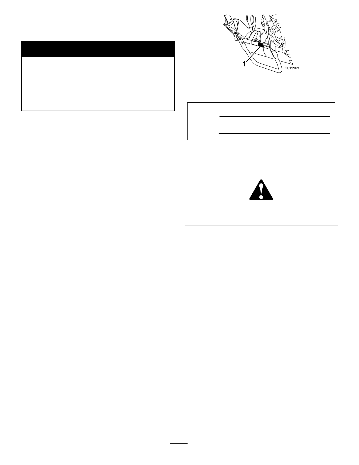
Figure1
1.Locationofthemodelandserialnumbers-Tractionunit
ModelNo.
SerialNo.
Thismanualidentiespotentialhazardsandhassafety
messagesidentiedbythesafetyalertsymbol(Figure2),
whichsignalsahazardthatmaycauseseriousinjuryordeath
ifyoudonotfollowtherecommendedprecautions.
Figure2
1.Safetyalertsymbol.
ThissparkignitionsystemcomplieswithCanadianICES-002.
Introduction
Thismachineisawalk-behind,reel-bladelawnmower
intendedtobeusedbyprofessional,hiredoperatorsin
commercialapplications.Itisprimarilydesignedforcutting
grassonwell-maintainedlawnsinparks,golfcourses,sports
elds,andoncommercialgrounds.Itisnotdesignedfor
cuttingbrush,mowinggrassandothergrowthalongside
highways,orforagriculturaluses.
Readthisinformationcarefullytolearnhowtooperateand
maintainyourproductproperlyandtoavoidinjuryand
productdamage.Youareresponsibleforoperatingthe
productproperlyandsafely .
YoumaycontactTorodirectlyatwww .Toro.comforproduct
andaccessoryinformation,helpndingadealer,ortoregister
yourproduct.
Wheneveryouneedservice,genuineToroparts,oradditional
information,contactanAuthorizedServiceDealerorToro
CustomerServiceandhavethemodelandserialnumbersof
yourproductready .Figure1identiesthelocationofthe
modelandserialnumbersontheproduct.Writethenumbers
inthespaceprovided.
Thismanualusestwootherwordstohighlightinformation.
Importantcallsattentiontospecialmechanicalinformation
andNoteemphasizesgeneralinformationworthyofspecial
attention.
©2013—TheToro®Company
8111LyndaleAvenueSouth
Bloomington,MN55420
Contactusatwww.T oro.com.
2
PrintedintheUSA.
AllRightsReserved

Contents
Introduction..................................................................2
Safety...........................................................................4
SafeOperatingPractices...........................................4
ToroMowerSafety..................................................5
ForModel04054.....................................................6
ForModel04055.....................................................6
ForModel04056.....................................................6
SafetyandInstructionalDecals.................................7
Setup............................................................................9
1InstallingandAdjustingtheHandle.........................9
2InstallingtheKickstand(ForGR800and
GR1600)...........................................................10
3InstallingtheTransportWheelShafts(For
GR1000andGR1600).........................................11
4InstallingtheTransportWheels(Optional)..............11
5AdjustingtheCuttingUnit....................................12
6InstallingtheGrassBasket....................................12
ProductOverview.........................................................13
Controls...............................................................13
Specications........................................................15
Attachments/Accessories........................................16
Operation....................................................................16
ThinkSafetyFirst...................................................16
CheckingtheEngineOilLevel.................................16
FillingtheFuelTank...............................................16
CheckingtheInterlockSwitchOperation...................17
StartingandStoppingtheEngine..............................18
DrivingtheMachineinTransport.............................18
PreparingtoMow...................................................18
PriortoMowing.....................................................18
MethodofMowing.................................................18
ControlOperation..................................................18
Maintenance.................................................................20
RecommendedMaintenanceSchedule(s)......................20
DailyMaintenanceChecklist....................................21
Lubrication...............................................................22
GreasingtheMachine.............................................22
EngineMaintenance..................................................23
ServicingtheEngineOil..........................................23
ServicingtheAirCleaner.........................................24
ReplacingtheSparkPlug.........................................24
FuelSystemMaintenance...........................................25
CleaningtheFuelFilter...........................................25
ElectricalSystemMaintenance....................................26
ServicingtheInterlockSwitch.................................26
BrakeMaintenance....................................................26
AdjustingtheService/ParkingBrake.........................26
BeltMaintenance......................................................28
AdjustingtheBelts.................................................28
ReplacingtheDifferentialBelt..................................30
ControlsSystemMaintenance.....................................31
AdjustingtheTractionControl.................................31
CuttingUnitMaintenance...........................................31
LevelingtheRearDrumtotheReel...........................31
AdjustingtheBedknifetotheReel............................32
AdjustingtheHeightofCut.....................................32
AdjustingtheGrassShieldHeight.............................33
AdjustingtheCut-OffBar.......................................34
BedbarIdentication..............................................34
SettingtheMachinetoMatchTurfConditions............35
ServicingtheBedbar...............................................36
BacklappingtheReel...............................................36
Storage........................................................................37
3

Safety
ThismachinemeetsorexceedsCENstandardEN836:1997,
ISOstandard5395:1990,andANSIB71.4-2004specications
ineffectatthetimeofproductionwhentheOperator
PresenceKit,PartNo.112-9282isinstalled.
Improperuseormaintenancebytheoperatororownercan
resultininjury.Toreducethepotentialforinjury,comply
withthesesafetyinstructionsandalwayspayattentiontothe
safetyalert
Danger—personalsafetyinstruction.Failuretocomplywith
theinstructionmayresultinpersonalinjuryordeath.
SafeOperatingPractices
ThefollowinginstructionsarefromtheCENstandardEN
836:1997,ISOstandard5395:1990,andANSIB71.4-2004.
Training
•ReadtheOperator'sManualandothertrainingmaterial
carefully.Befamiliarwiththecontrols,safetysigns,and
theproperuseoftheequipment.
•Neverallowchildrenorpeopleunfamiliarwiththese
instructionstouseorservicethemower.Local
regulationsmayrestricttheageoftheoperator.
•Nevermowwhilepeople,especiallychildren,oranimals
arenearby.
•Keepinmindthattheoperatororuserisresponsiblefor
accidentsorhazardsoccurringtootherpeopleortheir
property.
•Theowner/usercanpreventandisresponsiblefor
accidentsorinjuriesoccurringtohimselforherself,other
people,orproperty.
Preparation
•Whilemowing,alwayswearsubstantialfootwear,long
trousers,hardhat,safetyglasses,andhearingprotection.
Longhair,looseclothing,orjewelrymaygettangled
inmovingparts.Donotoperatetheequipmentwhen
barefootorwearingopensandals.
•Thoroughlyinspecttheareawheretheequipmentisto
beusedandremoveallobjectswhichmaybethrownby
themachine.
•Warning—Fuelishighlyammable.Takethefollowing
precautions:
–Storefuelincontainersspecicallydesignedforthis
–Refueloutdoorsonlyanddonotsmokewhile
–Addfuelbeforestartingtheengine.Neverremove
–Iffuelisspilled,donotattempttostarttheengine
symbol,whichmeansCaution,Warning,or
purpose.
refuelling.
thecapofthefueltankoraddfuelwhiletheengineis
runningorwhentheengineishot.
butmovethemachineawayfromtheareaofspillage
andavoidcreatinganysourceofignitionuntilfuel
vaporshavedissipated.
–Secureallfueltanksandcontainercaps.
•Replacefaultysilencers.
•Evaluatetheterraintodeterminewhataccessoriesand
attachmentsareneededtoproperlyandsafelyperform
thejob.Onlyuseaccessoriesandattachmentsapproved
bythemanufacturer.
•Checkthatoperator'spresencecontrols,safetyswitches
andshieldsareattachedandfunctioningproperly .Donot
operateunlesstheyarefunctioningproperly.
Operation
•Donotoperatetheengineinaconnedspacewhere
dangerouscarbonmonoxidefumescancollect.
•Mowonlyindaylightoringoodarticiallight.
•Beforeattemptingtostarttheengine,disengageallblade
attachmentclutches,shiftintoneutral,andengagethe
parkingbrake.
•Stayalertforholesintheterrainandotherhiddenhazards.
•Watchoutfortrafcwhencrossingornearroadways.
•Stopthebladesrotatingbeforecrossingsurfacesother
thangrass.
•Whenusinganyattachments,neverdirectdischargeof
materialtowardbystandersnorallowanyonenearthe
machinewhileinoperation.
•Neveroperatethemachinewithdamagedguards,shields,
orwithoutsafetyprotectivedevicesinplace.Besureall
interlocksareattached,adjustedproperly,andfunctioning
properly.
•Donotchangetheenginegovernorsettingsoroverspeed
theengine.Operatingtheengineatexcessivespeedmay
increasethehazardofpersonalinjury.
•Beforeleavingtheoperator'sposition:
–stoponlevelground;
–disengagethepowertake-offandlowerthe
attachments;
–changeintoneutralandsettheparkingbrake;
–stoptheengine.
•Disengagedrivetoattachmentswhentransportingornot
inuse.
•Stoptheengineanddisengagedrivetoattachment:
–beforerefuelling;
–beforeremovingthegrassbasket;
–beforemakingheightadjustmentunlessadjustment
canbemadefromtheoperator'sposition;
–beforeclearingblockages;
–beforechecking,cleaningorworkingonthemower;
–afterstrikingaforeignobjectorifanabnormal
vibrationoccurs.Inspectthemowerfordamage
andmakerepairsbeforerestartingandoperatingthe
equipment.
4

•Reducethethrottlesettingbeforestoppingengineand,if
theengineisprovidedwithafuelshut-offvalve,turnthe
valveoffattheconclusionofmowing.
•Keephandsandfeetawayfromthecuttingunit.
•Slowdownandusecautionwhenmakingturnsand
crossingroadsandsidewalks.Stopreelsifnotmowing.
•Donotoperatethemowerundertheinuenceofalcohol
ordrugs.
•Lightningcancausesevereinjuryordeath.Iflightning
isseenorthunderisheardinthearea,donotoperate
themachine;seekshelter.
•Usecarewhenloadingorunloadingthemachineintoa
trailerortruck.
•Usecarewhenapproachingblindcorners,shrubs,trees,
orotherobjectsthatmayobscurevision.
MaintenanceandStorage
•Keepallnuts,boltsandscrewstighttobesurethe
equipmentisinsafeworkingcondition.
•Neverstoretheequipmentwithfuelinthetankinsidea
buildingwherefumesmayreachanopenameorspark.
•Allowtheenginetocoolbeforestoringinanyenclosure.
•Toreducetherehazard,keeptheengine,silencer,and
fuelstorageareafreeofgrass,leaves,orexcessivegrease.
•Checkthegrassbasketfrequentlyforwearor
deterioration.
•Keepallpartsingoodworkingconditionandallhardware
andhydraulicttingstightened.Replaceallwornor
damagedpartsanddecals.
•Ifthefueltankhastobedrained,dothisoutdoors.
•Becarefulduringadjustmentofthemachinetoprevent
entrapmentofthengersbetweenmovingbladesand
xedpartsofthemachine.
•Disengagedrives,disengagethecuttingunit,setparking
brake,stopengineanddisconnectsparkplugwire.W ait
forallmovementtostopbeforeadjusting,cleaningor
repairing.
•Cleangrassanddebrisfromcuttingunit,drives,mufers,
andenginetohelppreventres.Cleanupoilorfuel
spillage.
•Carefullyreleasepressurefromcomponentswithstored
energy.
•Removethesparkplugwirebeforemakinganyrepairs.
•Usecarewhencheckingthereel.Wearglovesanduse
cautionwhenservicingthem.
•Keephandsandfeetawayfrommovingparts.Ifpossible,
donotmakeadjustmentswiththeenginerunning.
ToroMowerSafety
ThefollowinglistcontainssafetyinformationspecictoToro
productsorothersafetyinformationthatyoumustknowthat
isnotincludedintheCEN,ISO,orANSIstandard.
Thisproductiscapableofamputatinghandsandfeetand
throwingobjects.Alwaysfollowallsafetyinstructionsto
avoidseriousinjuryordeath.
Useofthisproductforpurposesotherthanitsintendeduse
couldprovedangeroustouserandbystanders.
•Knowhowtostoptheenginequickly.
•Donotoperatethemachinewhilewearingtennisshoes
orsneakers.
•Wearingsafetyshoesandlongpantsisadvisableand
requiredbysomelocalordinancesandinsurance
regulations.
•Handlegasolinecarefully .Wipeupanyspills.
•Checkthesafetyinterlockswitchesdailyforproper
operation.Ifaswitchshouldfail,replacetheswitch
beforeoperatingthemachine.
•Alwaysstandbehindthehandlewhenstartingand
operatingthemachine.
•Usingthemachinedemandsattention.Topreventloss
ofcontrol:
–Donotoperateclosetosandtraps,ditches,creeks,or
otherhazards.
–Reducespeedwhenmakingsharpturns.Avoid
suddenstopsandstarts.
–Whennearorcrossingroads,alwaysyieldthe
right-of-way.
•Thegrassbasketmustbeinplace,duringthemowing
operation,formaximumsafety.Shuttheengineoff
beforeemptyingthebasket.
•Donottouchtheengine,mufer,orexhaustpipewhile
theengineisrunningorsoonafterithasstoppedbecause
theseareascouldbehotenoughtocauseburns.
•Whenapersonorpetappearsunexpectedlyinornear
themowingarea,stopmowing.Carelessoperation,
combinedwithterrainangles,ricochets,orimproperly
positionedguardscanleadtothrownobjectinjuries.Do
notresumemowinguntiltheareaiscleared.
MaintenanceandStorage
•Checkallfuellinesfortightnessandwearonaregular
basis.Tightenorrepairthemasneeded.
•Iftheenginemustberunningtoperformamaintenance
adjustment,keephands,feet,clothing,andanypartsof
thebodyawayfromthecuttingunit,attachments,andany
movingparts.Keepeveryoneaway .
•Toensuresafetyandaccuracy,haveanAuthorizedToro
Distributorcheckthemaximumenginespeedwitha
tachometer.Maximumgovernedenginespeedshould
be3375±100RPM.
•Ifmajorrepairsareeverneededorifassistanceisdesired,
contactanAuthorizedToroDistributor.
•UseonlyToro-approvedattachmentsandreplacement
parts.Thewarrantymaybevoidedifusedwith
unapprovedattachments.
5

ForModel04054
ForModel04056
SoundPowerLevel
Thisunithasaguaranteedsoundpowerlevelof95dBA,
whichincludesanUncertaintyValue(K)of1dBA.
Soundpowerlevelwasdeterminedaccordingtothe
proceduresoutlinedinISO11094.
SoundPressureLevel
Thisunithasasoundpressurelevelattheoperator’searof85
dBA,whichincludesanUncertaintyValue(K)of1dBA.
Soundpressurelevelwasdeterminedaccordingtothe
proceduresoutlinedinEN836.
VibrationLevel
Hand-Arm
Measuredvibrationlevelforlefthand=4.00m/s
Measuredvibrationlevelforrighthand=2.87m/s
UncertaintyValue(K)=0.5m/s
Measuredvaluesweredeterminedaccordingtotheprocedures
outlinedinEN836.
2
2
2
SoundPowerLevel
Thisunithasaguaranteedsoundpowerlevelof95dBA,
whichincludesanUncertaintyValue(K)of1dBA.
Soundpowerlevelwasdeterminedaccordingtothe
proceduresoutlinedinISO11094.
SoundPressureLevel
Thisunithasasoundpressurelevelattheoperator’searof85
dBA,whichincludesanUncertaintyValue(K)of1dBA.
Soundpressurelevelwasdeterminedaccordingtothe
proceduresoutlinedinEN836.
VibrationLevel
Hand-Arm
Measuredvibrationlevelforrighthand=3.35m/s
Measuredvibrationlevelforlefthand=2.59m/s
UncertaintyValue(K)=1.7m/s
Measuredvaluesweredeterminedaccordingtotheprocedures
outlinedinEN836.
2
2
2
ForModel04055
SoundPowerLevel
Thisunithasaguaranteedsoundpowerlevelof95dBA,
whichincludesanUncertaintyValue(K)of1dBA.
Soundpowerlevelwasdeterminedaccordingtothe
proceduresoutlinedinISO11094.
SoundPressureLevel
Thisunithasasoundpressurelevelattheoperator’searof84
dBA,whichincludesanUncertaintyValue(K)of1dBA.
Soundpressurelevelwasdeterminedaccordingtothe
proceduresoutlinedinEN836.
VibrationLevel
Hand-Arm
Measuredvibrationlevelforrighthand=2.52m/s
Measuredvibrationlevelforlefthand=2.39m/s
2
2
UncertaintyValue(K)=1.3m/s
Measuredvaluesweredeterminedaccordingtotheprocedures
outlinedinEN836.
2
6
SafetyandInstructionalDecals
Safetydecalsandinstructionsareeasilyvisibletotheoperatorandarelocatednearanyareaofpotential
danger.Replaceanydecalthatisdamagedorlost.
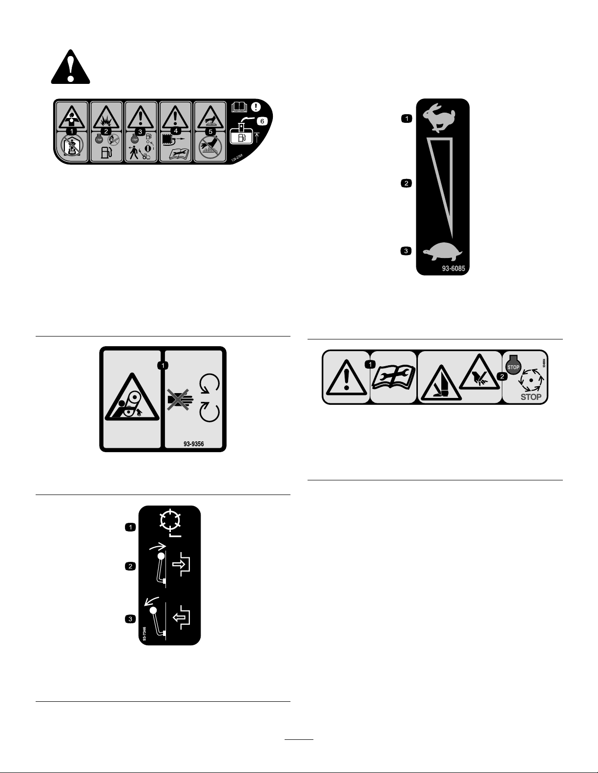
120–2769
1.Toxicgasinhalation
hazard—donotoperate
indoors.
2.Explosionhazard—stop
theengineandkeepaway
fromopenameswhen
refueling.
3.Warning—stoptheengine
andturnoffthefuelbefore
leavingthemachine.
4.Warning—disconnectthe
sparkplugwireandread
theinstructionbefore
servicingorperforming
maintenance.
5.Hotsurface/burn
hazard—donottouch
hotsurfaces.
6.Warning—readthe
Operator’sManual;when
addingfueltothetank,
onlylltothebottomof
thelltube.
93-9356
1.Entanglementhazard—stayawayfrommovingparts.
93-6085
1.Fast
2.Continuousvariable
setting
3.Slow
93-8064
1.Warning—readtheinstructionsbeforeservicingor
performingmaintenance.
2.Cuttinghazardoffootorhand—stoptheengineandwait
formovingpartstostop.
1.Reeldrive3.Disengage
2.Engage
93-7346
7
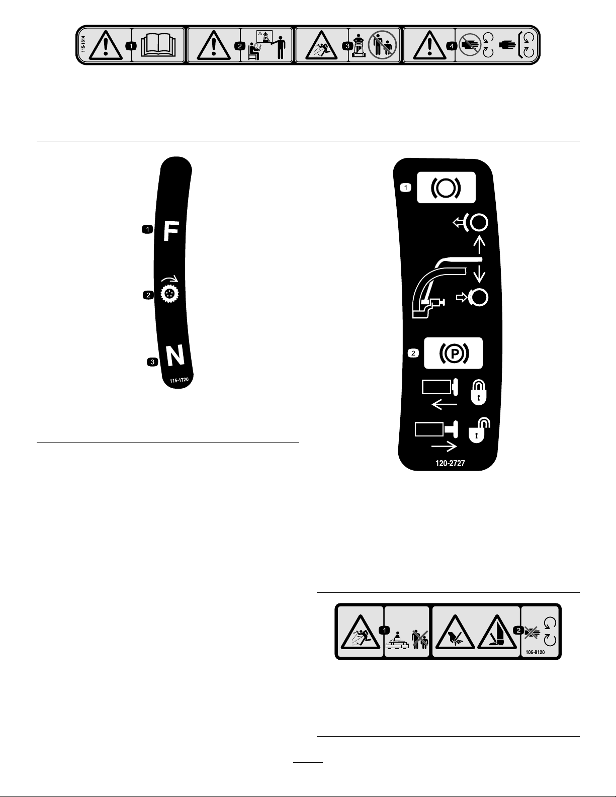
115-1614
1.Warning—readtheOperator'sManual.3.Thrownobjecthazard—keepbystandersasafedistancefrom
2.Warning—donotoperatethemachineunlessyouaretrained.
themachine.
4.Warning—stayawayfrommovingparts;keepallguardsin
place.
115-1720
1.Forward3.Neutral
2.Drivewheel
120-2727
1.Brake—toengage,pullthe
levertowardthehandle;
todisengage,releasethe
lever.
2.Parkingbrake—tolock,
pullthelevertowardthe
handle,pressthebutton
inandreleasethelever
againstthelockingbutton;
torelease,pullthelever
towardthehandleuntil
thebuttonreleasesand
releasethelever..
106-8120
1.Thrownobjecthazard—keepbystandersasafedistance
fromthemachine.
2.Cuttinghazardofhandandfoot—stayawayfrommoving
parts.
8
Setup
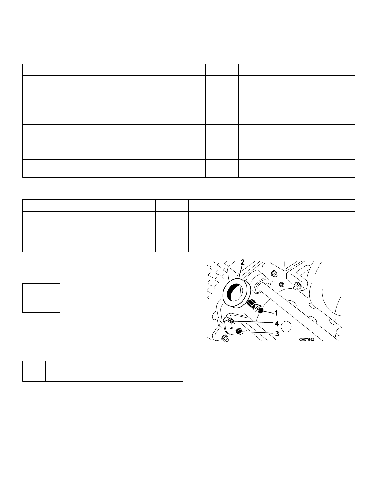
LooseParts
Usethechartbelowtoverifythatallpartshavebeenshipped.
ProcedureDescription
1
2
3
4
5
6
MediaandAdditionalParts
Description
Operator'sManual
EngineOperator'sManual
PartsCatalog
OperatorTrainingMaterial
CerticateofCompliance
Handle1
Cabletie
Kickstandassembly1
Spring
Wheelshaft,right
Wheelshaft,left
Transportwheels(optional)
Nopartsrequired
Grassbasket
Qty.
1
1
1
1
1
Readorviewbeforeoperatingthemachine
Qty.
4
1
1
1
2
–
1Installthegrassbasket.
Installthehandle.
Installthekickstand.
Installthetransportwheelshafts.
Installthetransportwheels(optional).
Adjustthecuttingunit.
Use
Use
Note:Determinetheleftandrightsidesofthemachine
fromthenormaloperatingposition.
1
InstallingandAdjustingthe Handle
Partsneededforthisprocedure:
1Handle
4
Cabletie
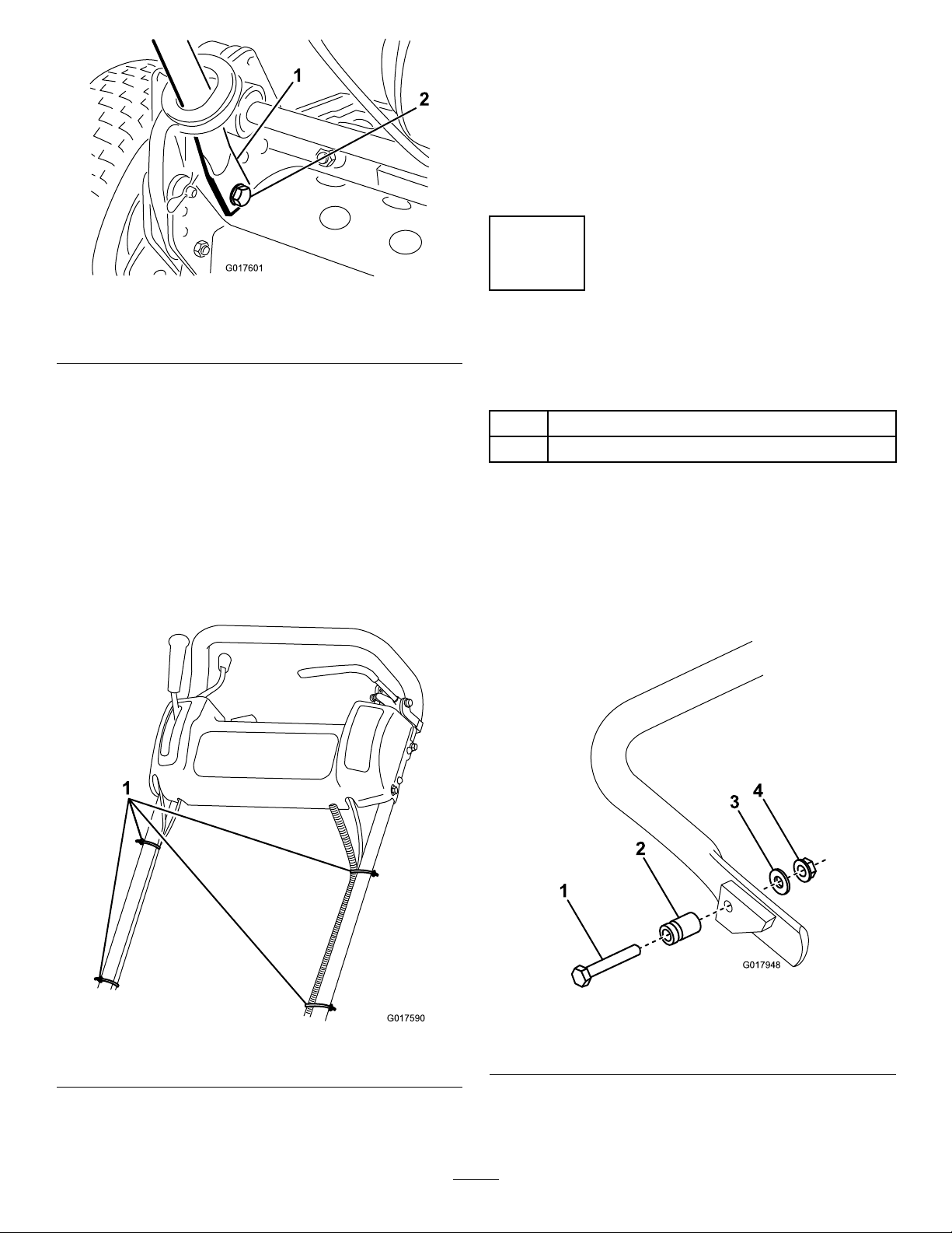
InstallingtheHandle
1.Removetheboltsandlocknutssecuringthebottomof
thehandlearmstoeachsideofthemower(Figure3).
Figure3
1.Mountingpins3.Boltandlocknut
2.Handlearms4.Hairpincotterandringpin
2.Removethehairpincottersandringpinssecuringthe
handlearmstotherearoftheframe(
3.Insertthehandleendsthroughtheholesinthehandle
armsandaligntheholeswiththemountingpins
(Figure3).
4.Squeezethehandleendsinwardandinstallthemonthe
mountingpins(Figure4).
Figure3).
9
2
G017601
G017590
1
AdjustingtheHandle
G017948
1
2
3
4
1.Removethehairpincottersfromtheringpinsoneach
sideofthemower(Figure3).
2.Whilesupportingthehandle,removetheringpins
fromeachsideandraiseorlowerthehandletothe
desiredoperatingposition(
3.Installtheringpinsandhairpincotters.
Figure3).
Figure4
1.Handleend
2.Bolt,washer,andlockwasher
5.Securethehandleendstothemountingpinswiththe
bolts,washers,andlockwashersprovided(Figure4).
6.Securethebottomofthehandlearmstoeachside
ofthemowerwiththeboltsandlocknutspreviously
removed(Figure4).Ensurethatyouinstallthe
bushingsinthehandlearmmountingholes.
7.Securethehandlearmstotherearoftheframewith
thehairpincottersandringpinspreviouslyremoved
(Figure4).
8.Securethecablesandwireharnesstothehandlewith
cableties(
Figure5).
2
InstallingtheKickstand(For GR800andGR1600)
Partsneededforthisprocedure:
1Kickstandassembly
1
Spring
Procedure
Note:Thefastenersareshippedlooselyinstalledonthe
kickstandassembly.
1.OntheGR1600only,connectthespringstudtothe
righthandsideofthekickstand(Figure6)usingthe
bolt,washer,andange-headnutprovided.
1.Cableties
Figure5
1.Bolt3.Washer
2.Springstud
2.Hookthespringintotheholeinthespringbracketand
ontothespringstudwhilealigningthekickstandwith
themountingholesintherearframe(
10
Figure6
4.Flange-headnut
Figure7).
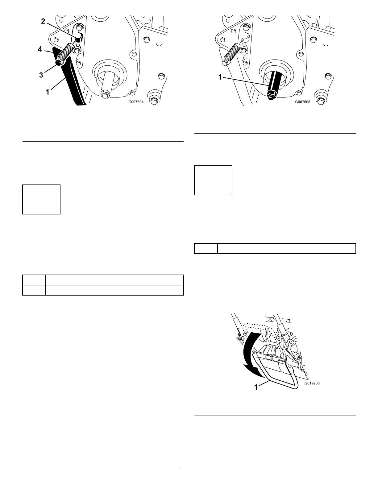
Figure7
G019968
1
Figure8
1.Kickstand
2.Springbracket4.Spring
3.Mountthekickstandtoeachsideoftheframewith
abolt,lockwasher,spacer,atwasherandlocknut
(Figure7).Positionthespacerinthekickstand
mountinghole.
3.Springstud
3
InstallingtheTransportWheel Shafts(ForGR1000and GR1600)
Partsneededforthisprocedure:
1
Wheelshaft,right
1
Wheelshaft,left
Procedure
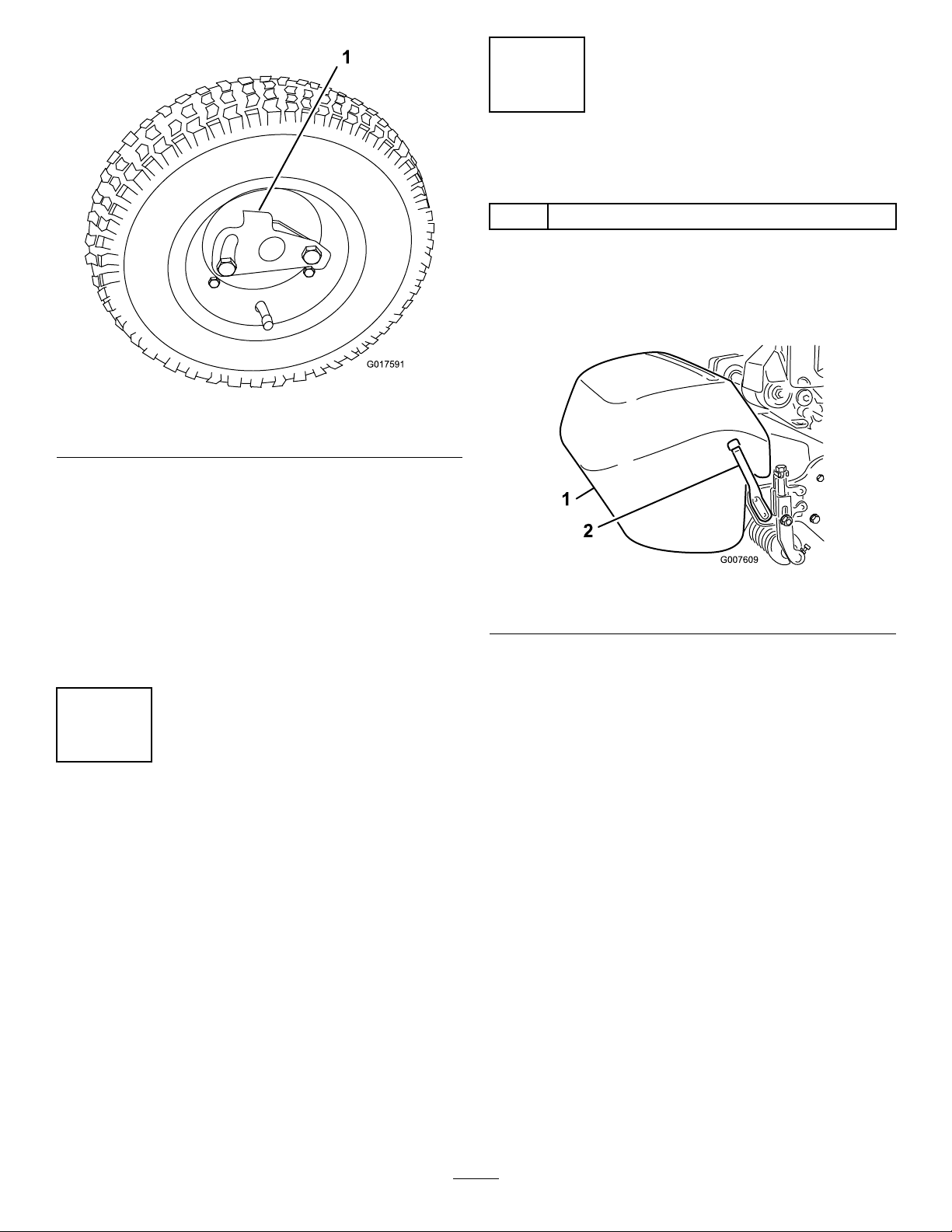
1.Rightwheelshaft
4.Torquetheshaftto65to75ft-lb(88to101N-m).
5.Repeatontheleftside.
4
InstallingtheTransport Wheels(Optional)
Partsneededforthisprocedure:
2
Transportwheels(optional)
Procedure
1.Pushthekickstanddownwithyourfootinthecenter
ofthekickstandandpulluponthemachinehandle
untilthekickstandhasrotatedforward,overcenter
(Figure9).
1.Pushthekickstanddownwithyourfootandpullup
onthehandletosupportthemoweronthekickstand.
2.Apply#242Loctitetothethreadsofthewheelshafts.
3.Threadtherightwheelshaftintothedrivepulleyon
therightsideofthemachine(Figure8).
Note:Therightwheelshafthaslefthandthreads.
Figure9
1.Kickstand
2.Pressthewheellockingcliptowardthecenterofthe
wheelontothewheelshaft(Figure10).
11
G017591
Figure10
1.Lockingclip
3.Rotatethewheelbackandforthuntilitslides
completelyontotheaxleandthelockingclipissecured
inthegrooveontheaxleshaft.
4.Repeattheprocedureontheoppositesideofthe
machine.
5.Inatethetiresto12to15psi.(574to718Pa).
6.Carefullylowerthemachineoffthekickstandby
pushingforwardslowly,allowingthekickstandto
springbacktoitsnormalposition.
6
InstallingtheGrassBasket
Partsneededforthisprocedure:
1
Grassbasket
Procedure
Graspthebasketbythetoplipandslideitontothebasket
mountingrods(Figure11).
Figure11
1.Grassbasket
Note:Model04056only—Whencuttinginhigher
heights-of-cut,thebasketmaybeloweredbyremovingeach
basketmountingrodandinstallingeachontheoppositeside
ofthemachine.
2.Basketmountingrod
5
AdjustingtheCuttingUnit
NoPartsRequired
Procedure
Beforeoperatingthemachine,completethefollowing
adjustments:
•LevelingtheRearDrumtotheReel(page31).
•AdjustingtheBedknifetotheReel(page32).
•AdjustingtheHeightofCut(page32).
•
AdjustingtheGrassShieldHeight(page33).
•AdjustingtheCut-OffBar(page34).
RefertotheCuttingUnitMaintenancesectioninMaintenance
forinstructionsonperformingtheseprocedures.
12
 Loading...