

Page 1

FormNo.3324-149RevA
Greensmaster
ModelNo.04052—SerialNo.200000001andUp
ModelNo.04052TE—SerialNo.200000001andUp
®
1000
Registeratwww.T oro.com.OriginalInstructions(EN)
Page 2

Warning
CALIFORNIA
Proposition65Warning
Theengineexhaustfromthisproduct
containschemicalsknowntotheStateof
Californiatocausecancer,birthdefects,
orotherreproductiveharm.
Becauseinsomeareastherearelocal,state,orfederal
regulationsrequiringthatasparkarresterbeusedonthe
engineofthismachine,asparkarresterisavailableas
anoption.Ifyourequireasparkarrestor,contactyour
AuthorizedServiceDealer.
GenuineTorosparkarrestersareapprovedbytheUSDA
ForestryService.
Important:ItisaviolationofCaliforniaPublic
ResourceCodeSection4442touseoroperate
theengineonanyforest-covered,brush-covered,
orgrass-coveredlandwithoutasparkarrester
mufermaintainedinworkingorder,ortheengine
constricted,equipped,andmaintainedforthe
preventionofre.Otherstatesorfederalareasmay
havesimilarlaws.
(Figure1),whichsignalsahazardthatmaycauseserious
injuryordeathifyoudonotfollowtherecommended
precautions.
Figure1
1.Safetyalertsymbol.
Thismanualusestwootherwordstohighlight
information.Importantcallsattentiontospecial
mechanicalinformationandNoteemphasizesgeneral
informationworthyofspecialattention.
ThissparkignitionsystemcomplieswithCanadian
ICES-002.
Introduction
Readthisinformationcarefullytolearnhowtooperate
andmaintainyourproductproperlyandtoavoidinjury
andproductdamage.Youareresponsibleforoperating
theproductproperlyandsafely.
YoumaycontactTorodirectlyatwww .Toro.comfor
productandaccessoryinformation,helpndinga
dealer,ortoregisteryourproduct.
Wheneveryouneedservice,genuineToroparts,or
additionalinformation,contactanAuthorizedService
DealerorToroCustomerServiceandhavethemodel
andserialnumbersofyourproductready .Themodel
andserialnumbersarelocatedonaplateontherear
frame.Writethenumbersinthespaceprovided.
ModelNo.
SerialNo.
Thismanualidentiespotentialhazardsandhas
safetymessagesidentiedbythesafetyalertsymbol
©2000,2008—TheToro®Company
8111LyndaleAvenueSouth
Bloomington,MN55420
Contactusatwww.Toro.com.
2
PrintedintheUSA.
AllRightsReserved
Page 3

Contents
Introduction.................................................................2
Safety...........................................................................4
SafeOperatingPractices.......................................4
ToroMowerSafety...............................................5
SoundPressure.....................................................6
Vibration..............................................................6
SafetyandInstructionalDecals.............................7
Setup............................................................................9
1InstallingandAdjustingtheHandle....................9
2InstallingtheTransportWheels
(Optional)......................................................10
3CheckingFluidLevels......................................10
4AdjustingtheCuttingUnit...............................10
5InstallingtheGrassBasket...............................11
ProductOverview......................................................11
Controls.............................................................11
Specications.....................................................12
Attachments/Accessories...................................12
Operation...................................................................13
ThinkSafetyFirst...............................................13
CheckingtheEngineOilLevel............................13
FillingtheFuelTank...........................................13
CheckingtheInterlockSwitchOperation............15
StartingandStoppingtheEngine........................15
DrivingtheMachineinTransport.......................15
PreparingtoMow...............................................15
Mowing..............................................................15
OperatingTips...................................................16
Maintenance...............................................................17
RecommendedMaintenanceSchedule(s)................17
DailyMaintenanceChecklist...............................18
Lubrication.............................................................19
GreasingtheMachine.........................................19
EngineMaintenance...............................................20
ServicingtheEngineOil.....................................20
ServicingtheAirCleaner....................................21
ReplacingtheSparkPlug....................................21
FuelSystemMaintenance.......................................22
CleaningtheFuelFilter.......................................22
BrakeMaintenance.................................................23
AdjustingtheService/ParkingBrake...................23
BeltMaintenance....................................................23
AdjustingtheBelts.............................................23
ReplacingtheDifferentialBelt............................25
ControlsSystemMaintenance.................................26
AdjustingtheTractionControl...........................26
CuttingUnitMaintenance.......................................27
LevelingtheRearDrumtotheReel.....................27
AdjustingtheBedknifetotheReel......................27
AdjustingtheHeightofCut................................28
AdjustingtheGrassShieldHeight.......................29
AdjustingtheCut-OffBar..................................29
ServicingtheBedbar..........................................29
BacklappingtheReel..........................................30
Storage.......................................................................31
3
Page 4

Safety
Improperuseormaintenancebytheoperatoror
ownercanresultininjury.T oreducethepotential
forinjury,complywiththesesafetyinstructionsand
alwayspayattentiontothesafetyalertsymbol,which
meansCaution,Warning,orDanger—personalsafety
instruction.Failuretocomplywiththeinstructionmay
resultinpersonalinjuryordeath.
SafeOperatingPractices
Training
•ReadtheOperator’sManualandothertraining
materialcarefully .Befamiliarwiththecontrols,
safetysigns,andtheproperuseoftheequipment.
•Iftheoperatorormechaniccannotreadthe
languageoftheOperator’sManualitistheowner’s
responsibilitytoexplainthismaterialtothem.
•Neverallowchildrenorpeopleunfamiliarwiththese
instructionstouseorservicethemower.Local
regulationsmayrestricttheageoftheoperator.
•Nevermowwhilepeople,especiallychildren,orpets
arenearby .
•Keepinmindthattheoperatororuserisresponsible
foraccidentsorhazardsoccurringtootherpeopleor
theirproperty.
•Theowner/usercanpreventandisresponsiblefor
accidentsorinjuriesoccurringtohimselforherself,
otherpeople,orproperty.
•Alloperatorsormechanicsmustbetrained.Itisthe
owner’sresponsibilityfortrainingusers.
Preparation
•Whilemowing,alwayswearsubstantialfootwear,
longtrousers,hardhat,safetyglasses,andhearing
protection.Longhair,looseclothing,orjewelrymay
gettangledinmovingparts.Donotoperatethe
equipmentwhenbarefootorwearingopensandals.
•Thoroughlyinspecttheareawheretheequipment
istobeusedandremoveallobjectswhichmaybe
thrownbythemachine.
•Warning—Fuelishighlyammable.Takethe
followingprecautions:
–Storefuelincontainersspecicallydesignedfor
thispurpose.
–Refueloutdoorsonlyanddonotsmokewhile
refuelling.
–Addfuelbeforestartingtheengine.Never
removethecapofthefueltankoraddfuelwhile
theengineisrunningorwhentheengineishot.
–Iffuelisspilled,donotattempttostartthe
enginebutmovethemachineawayfromthe
areaofspillageandavoidcreatinganysourceof
ignitionuntilfuelvaporshavedissipated.
–Replaceallfueltanksandcontainercapssecurely.
•Replacefaultysilencers.
•Evaluatetheterraintodeterminewhataccessories
andattachmentsareneededtoproperlyand
safelyperformthejob.Onlyuseaccessoriesand
attachmentsapprovedbythemanufacturer.
•Checkthatoperator’spresencecontrols,safety
switchesandshieldsareattachedandfunctioning
properly.Donotoperateunlesstheyarefunctioning
properly.
Operation
•Donotoperatetheengineinaconnedspacewhere
dangerouscarbonmonoxidefumescancollect.
•Mowonlyindaylightoringoodarticiallight.
•Beforeattemptingtostarttheengine,disengageall
bladeattachmentclutches,shiftintoneutral,and
engagetheparkingbrake.
•Donotuseonslopesofmorethan15°.
•Rememberthereisnosuchthingasasafeslope.
Travelongrassslopesrequiresparticularcare.To
guardagainstoverturning:
–donotstoporstartsuddenlywhengoingupor
downhill;
–engageclutchslowly,alwayskeepmachinein
gear,especiallywhentravellingdownhill;
–machinespeedsshouldbekeptlowonslopes
andduringtightturns;
–stayalertforhumpsandhollowsandother
hiddenhazards;
–nevermowacrossthefaceoftheslope,unless
themowerisdesignedforthispurpose.
•Stayalertforholesintheterrainandotherhidden
hazards.
•Watchoutfortrafcwhencrossingornearroadways.
•Stopthebladesrotatingbeforecrossingsurfaces
otherthangrass.
•Whenusinganyattachments,neverdirectdischarge
ofmaterialtowardbystandersnorallowanyonenear
themachinewhileinoperation.
•Neveroperatethemachinewithdamagedguards,
shields,orwithoutsafetyprotectivedevicesinplace.
4
Page 5

Besureallinterlocksareattached,adjustedproperly,
andfunctioningproperly .
•Donotchangetheenginegovernorsettingsor
overspeedtheengine.Operatingtheengineat
excessivespeedmayincreasethehazardofpersonal
injury.
•Beforeleavingtheoperator’sposition:
–stoponlevelground;
–disengagethecuttingunitandtractiondrive;
–settheparkingbrake;
–stoptheengine.
•Disengagedrivetoattachmentswhentransporting
ornotinuse.
•Stoptheengineanddisengagedrivetoattachment:
–beforerefuelling;
–beforeremovingthegrasscatcher;
–beforemakingheightadjustmentunless
adjustmentcanbemadefromtheoperator’s
position.
–beforeclearingblockages;
–beforechecking,cleaningorworkingonthe
mower;
–afterstrikingaforeignobjectorifanabnormal
vibrationoccurs.Inspectthemowerfordamage
andmakerepairsbeforerestartingandoperating
theequipment.
•Reducethethrottlesettingbeforestoppingengine
and,iftheengineisprovidedwithafuelshut-off
valve,turnthevalveoffattheconclusionofmowing.
•Keephandsandfeetawayfromthecuttingunit.
•Slowdownandusecautionwhenmakingturns
andcrossingroadsandsidewalks.Stopreelsifnot
mowing.
•Donotoperatethemowerundertheinuenceof
alcoholordrugs
•Usecarewhenloadingorunloadingthemachine
intoatrailerortruck
•Usecarewhenapproachingblindcorners,shrubs,
trees,orotherobjectsthatmayobscurevision.
MaintenanceandStorage
•Keepallnuts,boltsandscrewstighttobesurethe
equipmentisinsafeworkingcondition.
•Neverstoretheequipmentwithfuelinthetank
insideabuildingwherefumesmayreachanopen
ameorspark.
•Allowtheenginetocoolbeforestoringinany
enclosure.
•Toreducetherehazard,keeptheengine,silencer,
batterycompartmentandfuelstorageareafreeof
grass,leaves,orexcessivegrease.
•Checkthegrasscatcherfrequentlyforwearor
deterioration.
•Keepallpartsingoodworkingconditionandall
hardwareandhydraulicttingstightened.Replaceall
wornordamagedpartsanddecals.
•Ifthefueltankhastobedrained,dothisoutdoors.
•Becarefulduringadjustmentofthemachineto
prevententrapmentofthengersbetweenmoving
bladesandxedpartsofthemachine.
•Disengagedrives,disengagethecuttingunit,set
parkingbrake,stopengineanddisconnectsparkplug
wire.Waitforallmovementtostopbeforeadjusting,
cleaningorrepairing.
•Cleangrassanddebrisfromcuttingunit,drives,
mufers,andenginetohelppreventres.Cleanup
oilorfuelspillage.
•Carefullyreleasepressurefromcomponentswith
storedenergy.
•Removethesparkplugwirebeforemakingany
repairs.
•Usecarewhencheckingthereel.Wearglovesand
usecautionwhenservicingthem.
•Keephandsandfeetawayfrommovingparts.If
possible,donotmakeadjustmentswiththeengine
running.
ToroMowerSafety
Thefollowinglistcontainssafetyinformationspecic
toToroproductsorothersafetyinformationthatyou
mustknowthatisnotincludedintheCEN,ISO,or
ANSIstandard.
Thisproductiscapableofamputatinghandsand
feetandthrowingobjects.Alwaysfollowallsafety
instructionstoavoidseriousinjuryordeath.
Useofthisproductforpurposesotherthanitsintended
usecouldprovedangeroustouserandbystanders.
•Knowhowtostoptheenginequickly.
•Donotoperatethemachinewhilewearingtennis
shoesorsneakers.
•Wearingsafetyshoesandlongpantsisadvisableand
requiredbysomelocalordinancesandinsurance
regulations.
•Handlegasolinecarefully.Wipeupanyspills.
5
Page 6

•Checkthesafetyinterlockswitchesdailyforproper
operation.Ifaswitchshouldfail,replacetheswitch
beforeoperatingthemachine.
•Usingthemachinedemandsattention.Toprevent
lossofcontrol:
SoundPressure
Thisunithasamaximumsoundpressurelevelatthe
operator’searof83dBA,basedonmeasurementsof
identicalmachinesperEN836andISO11201.
–Donotdriveclosetosandtraps,ditches,creeks,
orotherhazards.
–Reducespeedwhenmakingsharpturns.Avoid
suddenstopsandstarts.
–Whennearorcrossingroads,alwaysyieldthe
right-of-way.
–Applytheservicebrakeswhengoingdownhillto
keepforwardspeedslowandtomaintaincontrol
ofthemachine.
•Thegrassbasketmustbeinplaceduringthemowing
operationformaximumsafety .Shuttheengineoff
beforeemptyingthebasket.
•Donottouchtheengine,mufer,orexhaustpipe
whiletheengineisrunningorsoonafterithas
stoppedbecausetheseareascouldbehotenough
tocauseburns.
•Whenapersonorpetappearsunexpectedlyinor
nearthemowingarea,stopmowing.Careless
operation,combinedwithterrainangles,ricochets,
orimproperlypositionedguardscanleadtothrown
objectinjuries.Donotresumemowinguntilthe
areaiscleared.
Vibration
Thisunitdoesnotexceedahand/armvibrationlevel
of10.05m/s
machinesperEN1033andEN836.
2
,basedonmeasurementsofidentical
MaintenanceandStorage
•Checkallfuellinesfortightnessandwearona
regularbasis.Tightenorrepairthemasneeded.
•Iftheenginemustberunningtoperforma
maintenanceadjustment,keephands,feet,clothing,
andanypartsofthebodyawayfromthecuttingunit,
attachments,andanymovingparts.Keepeveryone
away.
•Toensuresafetyandaccuracy ,haveanAuthorized
ToroDistributorcheckthemaximumenginespeed
withatachometer.Maximumgovernedenginespeed
shouldbe3600RPM.
•Ifmajorrepairsareeverneededorifassistanceis
desired,contactanAuthorizedToroDistributor.
•UseonlyToro-approvedattachmentsand
replacementparts.Thewarrantymaybevoidedif
usedwithunapprovedattachments.
6
Page 7
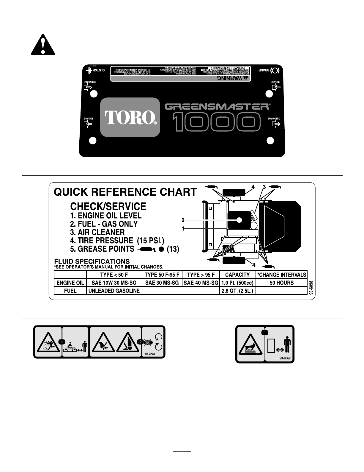
SafetyandInstructionalDecals
Safetydecalsandinstructionsareeasilyvisibletotheoperatorandarelocatednearanyareaof
potentialdanger.Replaceanydecalthatisdamagedorlost.
104-051
93-7273
1.Thrownobjecthazard—keepbystandersasafedistance
fromthemachine.
2.Cuttinghazardofhandorfoot—stayawayfrommoving
parts.
93-6098
93-8069
1.Hotsurface/burnhazard—stayasafedistancefromthe
hotsurface.
7
Page 8
93-7348
1.Warning—readtheOperator’sManual.
2.Firehazard—nore,openames,orsmoking;whenadding
fueltothetank,leavespacebetweenthefuelandthetopof
thetank.
3.Thrownobjecthazard—keepbystandersasafedistance
fromthemachine.
4.Cuttinghazardofhandorfoot—stayawayfrommoving
parts
93-9356
1.Entanglementhazard—stayawayfrommovingparts.
1.Fast
2.Continuousvariable
setting
1.Useunleadedgasoline.
93-6085
3.Slow
93-9886
1.Reeldrive3.Disengage
2.Engage
93-8064
1.Warning—readtheinstructionsbeforeservicingor
performingmaintenance.
2.Cuttinghazardofhandorfoot—stoptheengineandwait
formovingpartstostop.
93-7346
8
Page 9
Setup
LooseParts
Usethechartbelowtoverifythatallpartshavebeenshipped.
ProcedureDescription
Handle1
1
2
4
5
Cabletie
Transportwheels(obtainseparately)
Nopartsrequired
Grassbasket
MediaandAdditionalParts
Description
Operator’sManual
EngineOperator’sManual
PartsCatalog
OperatorTrainingMaterial
CerticateofCompliance
Note:Determinetheleftandrightsidesofthemachine
fromthenormaloperatingposition.
Qty.
Qty.
2
2Installthetransportwheels.
–
1Installthegrassbasket.
1
1
1
1
1
Readorviewbeforeoperatingthemachine
Installthehandle.
Adjustthecuttingunit.
Use
Use
1
InstallingandAdjustingthe
Handle
Partsneededforthisprocedure:
1Handle
2
Cabletie
InstallingtheHandle
1.Removethebolt,washer,andlockwasherfromthe
mountingpinoneachsideofthemower(Figure2).
Figure2
1.Mountingpins3.Boltandlocknut
2.Handlearms4.Hairpincotterandringpin
2.Insertthehandleendsthrutheholesinthehandle
armsandaligntheholeswiththemountingpins
(Figure2).
Note:Hairpincottersandringpinsmayhave
toberemovedfromhandlearmstoallowhandle
installation(Figure2).
3.Squeezethehandleendsinwardandinstallthemon
themountingpins(Figure3).
9
Page 10
Figure3
1.Handleend
4.Securethehandleendstothemountingpinswiththe
bolts,washers,andlockwasherspreviouslyremoved
(Figure3).
5.Securethecablestothehandlewithcableties.
Figure4
1.Lockingclip
AdjustingtheHandle
1.Removethehairpincottersfromtheringpinson
eachsideofthemower(Figure2).
2.Whilesupportingthehandle,removetheringpins
fromeachsideandraiseorlowerthehandletothe
desiredoperatingposition(Figure2).
3.Installtheringpinsandhairpincotters.
2
InstallingtheTransport
Wheels(Optional)
Partsneededforthisprocedure:
2
Transportwheels(obtainseparately)
Procedure
4.Rotatewheelbackandforthuntilitslidescompletely
ontoaxleandlockingclipissecuredingrooveon
axleshaft.
5.Repeatprocedureonoppositesideofmachine.
6.Inatethetiresto12to15psi.(574to718Pa).
3
CheckingFluidLevels
NoPartsRequired
Procedure
1.Checktheengineoillevel,refertoCheckingthe
EngineOilLevelinEngineMaintenance.
2.Checkthetransmissionuidlevel,refertoChecking
theTransmissionFluidLevelinDriveSystem
Maintenance.
1.Pushthekickstanddownwithyourfootandpull
uponthehandletosupportthemoweronthekick
stand.
2.ApplyNever–Seeztotheexposedendsoftheaxles
andslidethewheelontotheaxle(Figure4).
3.Pivotthewheellockingclipawayfromcenterof
thewheelallowingittoslidefartherontotheaxle
(Figure4).
10
Page 11

ProductOverview
4
AdjustingtheCuttingUnit
NoPartsRequired
Procedure
Beforeoperatingthemachine,completethefollowing
adjustments:
•Levelthereardrumtothereel.
•Adjustthebedknifetothereel.
•Adjusttheheight-of-cut.
•Adjustthegrassshieldheight
•Adjustthecut-offbar.
RefertotheCuttingUnitMaintenancesectionin
Maintenanceforinstructionsonperformingthese
procedures.
5
Controls
Figure6
1.Throttlecontrol
2.Tractiondrivelever
ThrottleControl
Thethrottlecontrol(Figure6)islocatedonrearright
sideofthecontrolpanel.Theleverconnectstoand
operatesthrottlelinkagetothecarburetor.Theengine
speedcanbevariedfrom1600to3600RPM.
3.Service/parkingbrake
4.Operatorpresencecontrol
(optional)
InstallingtheGrassBasket
Partsneededforthisprocedure:
1
Grassbasket
Procedure
Graspbasketbytoplipandslideitontothebasket
mountingrods(Figure5).
TractionDriveLever
Thetractiondrivelever(Figure6)islocatedonthefront
rightsideofthecontrolpanel.Ithastwopositions:
NeutralandForward.Pushingtheleverforwardengages
thetractiondrive.
Service/ParkingBrake
Theservice/parkingbrake(Figure6)islocatedonleft
frontsideofcontrolpanel.Youcanusethebraketo
sloworstopthemachine.Pullingtheleverbackover
centerwillsettheparkingbrake.Youmustreleasethe
brakebeforetractiondriveisengaged.
OperatorPresenceControl(Optional)
Ifequipped,theoperatorpresencecontrol(Figure6)
islocatedontherearofthehandle.Pushtheoperator
presencecontrolagainstthehandle.Ifequipped,the
operatorpresencecontrolmustbeengagedbefore
movingthetractiondriveleverortheenginewillstop.
1.Grassbasket
Figure5
2.Basketmountingrod
ReelDriveLever
Thereeldrivelever(Figure7)islocatedontheright
frontcornerofthemachine.Theleverhastwo
11
Page 12

positions:EngageandDisengage.Pulluponthelever
toengagethereelorpushitdowntodisengagethereel.
RecoilStarter
Pullrecoilstarterhandle(Figure9)tostartengine.
Figure7
1.Reeldrivelever
ChokeLever
Thechokelever(Figure8)islocatedonleftfrontofthe
engine.Theleverhastwopositions:RunandChoke.
MovethelevertotheChokepositionwhenstarting
acoldengine.AfterenginestartsmovelevertoRun
position.
Figure8
1.Chokelever2.Fuelshut-offvalve
Figure9
1.Recoilstarter
2.Kickstand
3.On/offswitch
Kickstand(Optional)
Thekickstand(Figure9)ismountedtotherearof
machineandisusedtoraisetherearofmachinefor
installationorremovalofthetransportwheels.
Specications
Width
Height
Lengthwithbasket
Dryweight(withbasketand
Wiehleroller;withoutwheels
orgroomingreel)
Widthofcut21inches(53cm)
Heightofcut5/64to1inch(0.2to2.5cm)
Clip0.16inch(0.4cm)
36inches(91cm)
47inches(1 19cm)
59inches(150cm)
208lb(94kg.)
FuelShut-OffValve
Thefuelshut-offvalve(Figure8)islocatedonleft
frontofengine.Thevalvehastwopositions:Closed
andOpen.Movethelevertotheclosedpositionwhen
storingortransportingmachine.Openthevalvebefore
startingtheengine.
On/OffSwitch
Theon/offswitch(Figure9)islocatedonthetopofthe
controlpanel.MoveswitchtotheOnpositiontostart
theengineandtheOffpositiontostoptheengine.
Attachments/Accessories
AselectionofToroapprovedattachmentsand
accessoriesareavailableforusewiththemachineto
enhanceandexpanditscapabilities.Contactyour
AuthorizedServiceDealerorDistributororgoto
www.Toro.comforalistofallapprovedattachments
andaccessories.
12
Page 13

Operation
Note:Determinetheleftandrightsidesofthe
machinefromthenormaloperatingposition.
ThinkSafetyFirst
Pleasecarefullyreadallofthesafetyinstructionsand
decalsinthesafetysection.Knowingthisinformation
couldhelpyouorbystandersavoidinjury.
CheckingtheEngineOilLevel
Checktheengineoillevelbeforeeachuseorevery8
operatinghours,refertoCheckingtheEngineOilLevel
inEngineMaintenance,page20.
FillingtheFuelTank
Important:Neverusemethanol,gasoline
containingmethanol,gasoholcontainingmore
than10%ethanol,gasolineadditives,premium
gasoline,orwhitegasbecausethefuelsystem
couldbedamaged.Donotmixoilwithgasoline.
Incertainconditions,gasolineisextremely
ammableandhighlyexplosive.Areor
explosionfromgasolinecanburnyouand
othersandcandamageproperty.
•Fillthefueltankoutdoors,inanopenarea,
whentheengineiscold.Wipeupany
gasolinethatspills.
•Neverllthefueltankinsideanenclosed
trailer.
•Donotllthefueltankcompletelyfull.Add
gasolinetothefueltankuntilthelevelis1
inch(2.5cm)belowthebottomoftheller
neck.Thisemptyspaceinthetankallows
gasolinetoexpand.
•Neversmokewhenhandlinggasoline,and
stayawayfromanopenameorwhere
gasolinefumesmaybeignitedbyaspark.
•Storegasolineinanapprovedcontainerand
keepitoutofthereachofchildren.Never
buymorethana30-daysupplyofgasoline.
Figure10
1.Fueltankcap2.Fuelgauge
•Donotoperatewithoutentireexhaust
systeminplaceandinproperworking
condition.
13
Page 14

Incertainconditionsduringfueling,static
electricitycanbereleasedcausingaspark
whichcanignitethegasolinevapors.Are
orexplosionfromgasolinecanburnyouand
othersandcandamageproperty.
•Alwaysplacegasolinecontainersonthe
groundawayfromyourvehiclebeforelling.
•Donotllgasolinecontainersinsidea
vehicleoronatruckortrailerbedbecause
interiorcarpetsorplastictruckbedliners
mayinsulatethecontainerandslowtheloss
ofanystaticcharge.
•Whenpractical,removegas-powered
equipmentfromthetruckortrailerand
refueltheequipmentwithitswheelsonthe
ground.
•Ifthisisnotpossible,thenrefuelsuch
equipmentonatruckortrailerfroma
portablecontainer,ratherthanfroma
gasolinedispensernozzle.
•Ifagasolinedispensernozzlemustbeused,
keepthenozzleincontactwiththerimof
thefueltankorcontaineropeningatall
timesuntilfuelingiscomplete.
Gasolineisharmfulorfatalifswallowed.
Long-termexposuretovaporscancauseserious
injuryandillness.
•Avoidprolongedbreathingofvapors.
•Keepfaceawayfromnozzleandgastankor
conditioneropening.
•Keepgasawayfromeyesandskin.
1.Cleanaroundfueltankcapandremovecapfrom
tank(Figure10).
2.Usingunleadedgasoline,llfueltanknohigher
thantobottomoflterscreen.Donotoverll.
3.Installfueltankcapandwipeupanyspilledgasoline.
14
Page 15

CheckingtheInterlockSwitch
Operation
ServiceInterval:Beforeeachuseordaily
Ifsafetyinterlockswitchesaredisconnected
ordamagedthemachinecouldoperate
unexpectedlycausingpersonalinjury.
•Donottamperwiththeinterlockswitches.
•Checktheoperationoftheinterlock
switchesdailyandreplaceanydamaged
switchesbeforeoperatingthemachine.
1.PlacetractionleverintoEngagepositionandengine
controlsinstartingposition.
2.Attempttostartengine.
Theengineshouldnotstart.Ifenginestarts,the
interlockswitchneedsservice.Correctproblem
beforeoperating.RefertoServicingInterlock
Switch.
StartingandStoppingthe
Engine
Note:Forillustrationsanddescriptionsofthecontrols
referencedinthissection,refertotheControlssection
inProductOverview.
StartingtheEngine
Note:Ensurethatthesparkplugwireisinstalledon
thesparkplug..
1.Ensurethatthetractionandreeldriveleversarein
theDisengagedposition.
Note:Theenginewillnotstartifthetractionlever
isintheEngagedposition.
2.Openthefuelshut-offvalveontheengine.
3.Movetheon/offswitchtotheOnposition.
4.MovethethrottlecontroltotheFastposition.
5.MovethechokeleverhalfwaybetweentheOnand
Offpositionswhenstartingacoldengine.The
chokemaynotberequiredwhenstartingawarm
engine.
6.Pulltherecoilstarterhandleoutuntilpositive
engagementresults,thenpullitvigorouslytostart
theengine.
outbecauseropemaybreakorrecoilassembly
maybedamaged.
7.MovethechoketotheOffpositionastheengine
warmsup.
StoppingtheEngine
1.Movethetractionandreeldrivecontrolstothe
Disengagedposition,thethrottlecontroltothe
Slowposition,andtheOn/OffswitchtotheOff
position.
2.Pullthesparkplugwireoffofthesparkplugto
preventthepossibilityofaccidentalstartingbefore
storingthemachine.
3.Closethefuelshut-offvalvebeforestoringor
transportingthemowerinavehicle.
DrivingtheMachinein
Transport
1.Pushthekickstanddownwithyourfootandpull
uponthehandletoraisetherearofmowerand
installthetransportwheels.
2.Toreleasethekickstand,pulluponthehandle,
pushthemowerforward,andthenlowertherearof
mowerontothetransportwheels.
3.Ensurethatthetractionandreeldrivecontrolsare
intheDisengagedpositionandstarttheengine.
4.SetthethrottlecontroltoSlow ,tipthefrontofthe
machineupgradually,engagethetractiondriveand
slowlyincreasetheenginespeed.
5.Adjustthethrottletooperatethemoweratthe
desiredgroundspeedandtransportthemowerto
thedesireddestination.
PreparingtoMow
1.ReturnthetractioncontrollevertotheDisengage
position,thethrottletotheSlowposition,andstop
theengine.
2.Pushthekickstanddownwithyourfootandpull
upandbackonthehandletoraisethewheelsoff
oftheground.
3.Pushthelockingclipsonthewheelsoutofthe
groovesintheshafts.
4.Slidethewheelsoffoftheshafts.
5.Movetheunitoffofthekickstand.
Mowing
Important:Donotpullrecoilropetoitslimit
orletgoofstarterhandlewhenropeispulled
Properuseofthemachineprovidesthesmoothest
turfcuttingavailable.ReferalsotoOperatingTips
15
Page 16

forfundamentalsuggestionstoobtaintheutmost
performancefromyourmower.
Important:Excessiveoperationofthecuttingunit
withtheabsenceofgrassclippings(lubricant)can
damagethecuttingunit.
1.Starttheengine,setthethrottleatreducedspeed,
pushdownonthehandletoraisethecuttingunit,
movethetractionlevertotheEngagedposition,
andtransportthemowerontocollarofthegreen.
2.MovethetractionlevertotheDisengagedposition
andmovethereeldrivelevertotheEngaged
position.
3.MovethetractionlevertotheEngagedposition,
increasethethrottlespeeduntilthemoweris
travelingatthedesiredgroundspeed,drivethe
mowerontothegreen,lowerthefrontofthe
mower,andcommenceoperation.
4.Whennishedmowing,driveoffofthegreen,
movethetractioncontrollevertotheDisengage
position,stoptheengineandpushthereeldrive
leverintotheDisengageposition.
5.Emptythegrasscatcherofclippings,installthe
grasscatcher,andcommencetransportoperation.
OperatingTips
BeforeMowing
•Ensurethatthemoweriscarefullyadjustedand
issetevenlyonbothsidesofthereel.Improper
moweradjustmentismagniedmanytimesoverin
theappearanceoftheclippedturf.
•Removeallforeignobjectsfromtheturfpriorto
mowing.
•Ensurethateveryone,especiallychildrenandpets,
areclearoftheworkarea.
MowingTechniques
•Mowagreeninastraightbackandforthdirection,
acrossthegreen.
•Avoidcircularmowingorturningthemowerona
greenbecausescufngmayoccur.Turnthemower
offofthegreenbyraisingthecuttingreel(pushing
thehandledown)andturningonthetractiondrum.
•Mowatanormalwalkingpace.Fastspeedsaves
verylittletimeandwillresultinaninferiormowing
job.
16
Page 17

Maintenance
Note:Determinetheleftandrightsidesofthemachinefromthenormaloperatingposition.
RecommendedMaintenanceSchedule(s)
MaintenanceService
Interval
Aftertherst8hours
Aftertherst25hours
Beforeeachuseordaily
Every25hours
Every50hours
Every100hours
Every200hours
Every300hours
Beforestorage
Important:Refertoyour
MaintenanceProcedure
•Changetheengineoil.
•Cleanthefuellter.
•Checktheinterlockswitchoperation.
•Checktheengineoillevel.
•Greasethemachine.
•Cleanandoiltheaircleanerfoamelement.(Moreoftenindirtyordustyconditions)
•Changetheengineoil.(Morefrequentlyindustyordirtyconditions)
•Cleanthefuellter.
•Cleanorreplacethepaperairlterelement.(Moreoftenindirtyordustyconditions)
•Checkthesparkplug.
•Decarbontheengine.
•Changetheairlterpaperelement
•Paintchippedsurfaces.
Engine Operator’ s Man ual
foradditionalmaintenanceprocedures.
17
Page 18

DailyMaintenanceChecklist
Important:Duplicatethispageforroutineuse.
Maintenance
CheckItem
Checkthe
safetyinterlock
operation.
Checktheparking
brakeoperation.
Checkthefuel
level.
Checktheengine
oillevel.
Checktheair
lter.
Cleantheengine
coolingns.
Checkforunusual
enginenoises.
Checkforunusual
operatingnoises.
Checkthe
reel-to-bedknife
adjustment.
Checkthe
height-of-cut
adjustment.
Greaseallttings.
Touchup
damagedpaint.
Fortheweekof:
Mon.Tues.Wed.Thurs.Fri.
Sat.Sun.
NotationforAreasofConcern
Inspectionperformedby:
ItemDate
Information
18
Page 19

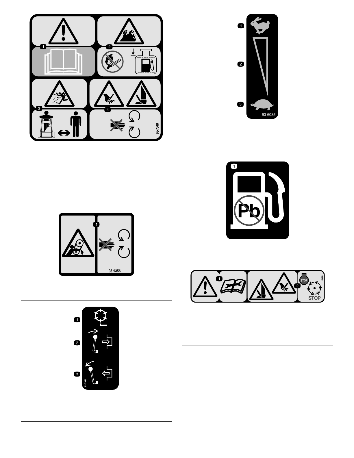
Lubrication
GreasingtheMachine
ServiceInterval:Every25hours
Lubricatethe13greasettingsonthemowerusing
aNo.2multipurposelithiumbasegrease.Ahand
operatedgreasegunisrecommendedforbestresults.
Thegreasettinglocationsareasfollows:
•2onthefrontroller(Figure11)
•2onthereelbearings(Figure11)
•2onthedrumaxles(Figure12)
•3onthedifferential(Figure12)
•2onthereelcountershaftbearings(Figure13)
•2onthebeltidlerpivots(Figure14)
1.Wipeeachgreasettingwithacleanrag.
2.Pumpgreaseintoeachttinguntilitbeginstoget
difculttopumpthegun.
Important:Donotapplytoomuchpressureor
greasesealswillbecomepermanentlydamaged.
3.Wipeoffexcessgrease.
Figure13
Figure14
Figure11
Figure12
19
Page 20

EngineMaintenance
ServicingtheEngineOil
ServiceInterval:Aftertherst8hours—Changethe
engineoil.
Beforeeachuseordaily—Checkthe
engineoillevel.
Every50hours—Changetheengine
oil.(Morefrequentlyindustyordirty
conditions)
Thecrankcasemustbelledwithapproximately20
uidouncesofproperviscosityoilbeforestaring.The
engineusesanyhigh-qualityoilhavingtheAmerican
PetroleumInstitute-APl-“serviceclassication"SF,
SG,SHorSJ.Oilviscosity-weight-mustbeselected
accordingtoambienttemperature.illustratesthe
temperature/viscosityrecommendations.
Figure16
1.Oillevelgauge
2.Removetheoillevelgaugebyrotatingit
counterclockwise.
2.Drainplug
Figure15
Note:Usingmulti-gradeoils(5W-20,10W-30,and
10W-40)willincreaseoilconsumption.Checktheoil
levelmorefrequentlywhenusingthem.
CheckingtheEngineOilLevel
1.Positionmowersotheengineislevelandclean
aroundoillevelgauge(Figure16).
3.Wipetheoillevelgaugecleanandinsertitintothe
llerport.Donotscrewitintotheport.
4.Removethegaugeandchecktheleveloftheoil.
5.Ifthelevelislow,addonlyenoughoiltoraisethe
leveluntilitisbetweentheHandLmarksonthe
gauge(Figure17).Donotoverll.
Figure17
6.Installtheoillevelgaugeandwipeupanyspilledoil.
ChangingtheEngineOil
1.Startandruntheengineforafewminutestowarm
theengineoil.
2.Placeadrainpanattherearofmachine,underthe
drainplug(Figure16).
3.Removethedrainplug.
20
Page 21

4.Pushdownonthehandletotipthemowerandthe
enginebackward,allowingmoreoiltorunintothe
drainpan.
5.Installthedrainplugandrellthecrankcasewiththe
properoil;refertoCheckingtheEngineOilLevel.
ServicingtheAirCleaner
ServiceInterval:Every25hours—Cleanandoiltheair
cleanerfoamelement.(Moreoftenin
dirtyordustyconditions)
Every100hours—Cleanorreplace
thepaperairlterelement.(More
oftenindirtyordustyconditions)
Every300hours—Changetheair
lterpaperelement
Important:Servicetheaircleanermoreoftenin
dirtyordustyconditions
1.Makesurethewireisoffofthesparkplug.
2.Removethewingnutssecuringtheaircleanercover
andremovethecover(Figure18).
Figure19
1.Foamelement2.Paperelement
5.Checkconditionofthepaperelement.Cleanby
gentlytappingthelterorreplaceitasrequired.
Important:Donotusecompressedairtoclean
thepaperelement.
6.Installthefoamelement,paperelement,andair
cleanercover.
Important:Donotoperatetheenginewithout
theaircleanerelementbecauseextremeengine
wearanddamagewilllikelyresult.
Figure18
1.Aircleanercover
3.Cleanthecoverthoroughly .
4.Ifthefoamelementisdirty,removeitfromthepaper
element(Figure19)andcleanthoroughly,asfollows:
A.Washthefoamelementinasolutionofliquid
soapandwarmwater.Squeezeittoremovedirt,
butdonottwistitbecausethefoammaytear.
B.Drythefoamelementbywrappingitinaclean
rag.Squeezetheragandfoamelementtodry
it,butdonottwistit.
C.Saturatethefoamelementwithcleanengineoil.
Squeezetheelementtoremoveexcessoiland
todistributetheoilthoroughly.Anoildamp
elementisdesirable.
ReplacingtheSparkPlug
ServiceInterval:Every100hours
UseanNGKBPR5ESsparkplugorequivalent.The
correctairgapis0.028-0.032inch.
1.Pullthemoldedwireoffofthesparkplug(Figure20).
Figure20
1.Sparkplugwire
2.Cleanaroundthesparkplugandremoveitfromthe
cylinderhead.
Important:Replaceacracked,fouled,ordirty
sparkplug.Donotsandblast,scrape,orclean
electrodesbecauseenginedamagecouldresult
fromgritenteringthecylinder.
21
Page 22

3.Settheairgapat0.028to0.032inch(0.05to0.07
cm)(Figure21).
FuelSystem
Maintenance
CleaningtheFuelFilter
ServiceInterval:Aftertherst25hours
Every50hours
Figure21
4.Installthecorrectlygappedsparkplugandtighten
itto17ft.-lb(23N-m).
5.Installthesparkplugwireonthesparkplug.
1.Closethefuelshutoffvalveandunscrewthebowl
fromthelterbody(Figure22).
Figure22
1.Shut-offvalve
2.Cleanthebowlandlterincleangasolineandinstall
it.
2.Bowl
22
Page 23

BrakeMaintenance
BeltMaintenance
AdjustingtheService/Parking
Brake
Ifservice/parkingbrakeslipswhenoperated,an
adjustmentisrequired.
1.Moveservice/parkingbrakelevertotheOff
position.
2.LoosentheretainersecuringtheV-beltcoverand
pivotthecoveropen.
3.Toincreasethecabletension,loosenthefront
cablejamnutandtightenthebackcablejamnut
(Figure23)untilaforceof3to5lb(1.5to2.3kg)
isrequiredtoengagethebrake.Measuretheforce
attheleverknob.Donotover-adjustitsothatthe
brakebanddrags.
AdjustingtheBelts
Ensurethatthebeltsareproperlytensionedtoensure
properoperationofthemachineandunnecessarywear.
Checkbeltsfrequently.
AdjustingtheReelDriveBelt
1.Removethebeltcovermountingfastenersandbelt
covertoexposethebelt(Figure24).
Figure24
1.Beltcover
Figure23
1.Tractioncable
4.Closethecoverandsecuretheretainer.
2.Service/parkingbrake
cable
2.Checkthetensionbypressingthebeltatmidspan
ofthepulleys(Figure25)with3to5lbofforce.The
beltshoulddeect1/4inch(0.63cm).
Figure25
1.Reeldrivebelt2.Idlerpulley
3.Completethefollowingtoadjustthebelttension:
A.Loosentheidlerpulleymountingnutandpivot
theidlerpulleyclockwiseagainstthebacksideof
thebeltuntilyouattainthedesiredbelttension
(Figure25).
Important:Donotovertensionthebelt.
B.Tightenthenuttolocktheadjustment.
23
Page 24

4.Installthebeltcoverbyplacingitinposition.
B.Tightenthenuttolocktheadjustment.
5.Whilemaintainingaslightgapbetweenthecover
sealandthesideplate,installeachmountingbolt
untilthethreadsengageintheinsert.Thegapallows
visualalignmentoftheboltstothethreadedinserts.
6.Afterallboltsareinstalled,tightenthemuntilthe
stand-offsinsidethecovercontactthesideplate.Do
notovertighten.
AdjustingtheTractionDriveBelt
1.Removethebeltcovermountingfastenersandthe
beltcovertoexposethebelt(Figure26).
4.Installthebeltcoverbyplacingitinposition.
5.Whilemaintainingaslightgapbetweenthecover
sealandthesideplate,installeachmountingbolt
untilthethreadsengageintheinsert.Thegapallows
visualalignmentoftheboltstothethreadedinserts.
6.Afterallboltsareinstalled,tightenthemuntilthe
stand-offsinsidethecovercontactthesideplate.Do
notovertighten.
AdjustingtheDifferentialBelt
1.Removetheboltssecuringthefrontandrearsections
ofthedifferentialcovertothedifferentialhousing
andslidethecoversectionsawaytoexposethebelt.
2.Checkthetensionbypressingthebeltatmidspan
ofthepulleys(Figure28)with4to6lbofforce.The
beltshoulddeect1/4inch(0.63cm).
Figure26
1.Tractiondrivebeltcover
2.Checkthetensionbypressingthebeltatmidspanof
thepulleys(Figure27)with3to5lb(1.5to2.3kg)
offorce.Thebeltshoulddeect1/4inch(0.63cm).
Figure27
1.Tractiondrivebelt2.Idlerpulley
3.Completethefollowingtoadjustthebelttension:
A.Loosentheidlerpulleymountingnutandpivot
theidlerpulleyclockwiseagainstthebacksideof
thebeltuntilthedesiredbelttensionisattained
(Figure27).
Important:Donotovertensionthebelt.
Figure28
1.Differentialbelt
2.Idlerpulley
3.Completethefollowingtoadjustthebelttension:
A.Loosentheidlerpulleymountingnutandpivot
theidlerpulleyclockwiseagainstthebacksideof
thebeltuntilthedesiredbelttensionisattained
(Figure28).
Important:Donotovertensionthebelt.
B.Tightenthenuttolocktheadjustment.
4.Installthebeltcoverbyplacingitinposition.
5.Whilemaintainingaslightgapbetweenthecover
sealandthesideplate,installeachmountingbolt
untilthethreadsengageintheinsert.Thegapallows
visualalignmentoftheboltstothethreadedinserts.
6.Afterallboltsareinstalled,tightenthemuntilthe
stand-offsinsidethecovercontactthesideplate.Do
notovertighten.
24
Page 25

AdjustingthePrimaryV-Belts
1.ToadjustthebelttensiononprimaryV -belts,rst
checktheadjustmentofthetractioncontrol.Refer
toAdjustingtheTractionControl.Ifunabletoattain
the3to5lb(1.5to2.3kg)forcerequiredinadjusting
thetractioncontrol,proceedtonextstep.
2.LoosentheretainersecuringtheV-beltcoverand
pivotthecoveropen(Figure29).
Figure29
1.V-beltcover2.Retainer
Figure30
1.PrimaryV-belts3.Idlerpulley
2.Beltguide
7.Tightenthemountingscrewsandcheckthe
alignment.
8.Topushorpullthemachineeasierwithoutstarting
theengine,adjustthebeltguide(Figure30,inset)
asfollows:
A.Engagetheclutch.
3.Toincreasebelttension,loosentheenginemounting
boltsandmoveenginebackwardsintheslots.
Important:Donotovertensionthebelt.
4.Tightenthemountingbolts.
Note:Thedistancebetweenthecentersofthe
driverandthedrivenpulleysshouldbeapproximately
5.18inches(13.15cm)afternewV-beltsareinstalled.
5.AftertensioningtheprimaryV-belts,checkthe
alignmentoftheengineoutputshaftpulleyandthe
countershaftpulleywithastraightedge.
6.Ifthepulleysaremisaligned,loosenthescrews
securingtheenginemountingbasetothemower
frameandslidetheenginefromsidetosideuntilthe
pulleysarealignedwithin0.030inch(0.07cm).
B.Loosentheboltsecuringtheidlerpulleyandbelt
guidetotheidlerarm.
C.Rotatethebeltguideclockwiseuntilagapof
approximately0.06inch(0.15cm)isobtained
betweentheguidengerandthebacksideofthe
drivebelts.
D.Tightentheboltandlocknutsecuringtheidler
pulleyandbeltguidetotheidlerarm.
9.Closethecoverandsecuretheretainer.
ReplacingtheDifferentialBelt
1.Removetheboltssecuringthetractiondriveandreel
drivebeltcoverstotherightsideplateandremove
thebeltcovers.
2.Loosentheidlerpulleymountingnut,oneachidler
pulley,andpivoteachidlerpulleycounterclockwise
awayfromthebacksideofeachbelttoreleasebelt
tension.
3.Removethebelts.
4.Removetheboltssecuringthefrontandrearsections
ofthedifferentialcovertothedifferentialhousing
andslidethecoversectionsawaytoexposethebelt
(Figure31).
25
Page 26

Figure31
1.Differentialcoversections
2.Frontclutchhousing
5.Loosentheidlerpulleymountingnutonthe
differentialidlerpulleyandpivottheidlerpulley
counterclockwiseawayfromthebacksideofthebelt
toreleasethebelttension.
6.Removethe2boltsandlocknutssecuringthefront
clutchhousingtothesideplate(Figure31).
3.Rightrearbearinghousing
ControlsSystem
Maintenance
AdjustingtheTractionControl
Iftractioncontroldoesnotengageoritslipsduring
operation,anadjustmentisrequired.
1.MovethetractioncontroltotheDisengaged
position.
2.LoosentheretainersecuringtheV-beltcoverand
pivotthecoveropen(Figure29).
3.Toincreasethecabletension,loosenthefront
cablejamnutandtightenthebackcablejamnut
(Figure32)untilaforceof3to5lb(1.5to2.3kg)is
requiredtoengagethetractioncontrol.Measurethe
forceatthecontrolknob.
Measuretheforceatthecontrolknob.
7.Rotatethehousing180°sothebottomofthe
housingpointsupward.
8.Removethe2boltsandlocknutssecuringtheright
rearbearinghousingtothesideplate(Figure31).
9.Rotatethehousing180°sothebottomofthe
housingpointsupward.Removeoldbelt.
10.Slidethenewbeltovertherotatedhousingcovers,
thedifferentialcoversections,andontothe
differentialpulleys.
11.Ensurethattheidlerpulleyispositionedagainstthe
backsideofbelt.
12.Rotatebothhousingsbackintotheuprightposition
andsecurethemtothesideplatewiththeboltsand
nutspreviouslyremoved.
13.Adjustthedifferentialbelttension;refertoAdjusting
theDifferentialBelt.
14.Adjustthebelttensiononthetractiondriveandreel
drivebelts;refertoAdjustingtheTractionDrive
Belt,andAdjustingtheReelDriveBelt
Figure32
1.Tractioncable2.Frontjamnut
4.Tightenfrontcablejamnut.
5.Closethecoverandsecuretheretainer.
6.Checkthetractioncontroloperation.
15.Installthedifferential,tractiondrive,andreeldrive
covers.
26
Page 27

CuttingUnitMaintenance
LevelingtheRearDrumtothe
Reel
1.Positionthemachineonaat,levelsurface,
preferablyaprecisionsteelworkplate.
2.Placea1/4x1inch(0.6x2.5cm)atsteelstrip,
approximately29inches(73.6cm)long,underthe
reelbladesandagainstthefrontedgeofthebedknife
topreventthebedbarfromrestingonthework
surface.
3.Raisethefrontrollersoonlythereardrumandreel
areonthesurface.
4.Firmlypressdownonthemachineabovethereelso
allreelbladescontactthesteelstrip.
5.Whilepressingdownonthereel,slideafeelergauge
underoneendofthedrum,thenchecktheother
endofthedrum.
Ifthereisagapbetweenthedrumandthework
surface,greaterthan0.010inch(.025cm),oneither
end,adjustthedrum(proceedtostep6).Ifthegap
islessthan0.010inch(.025cm)noadjustmentis
required.
Figure34
1.Drivepulley3.IdlerPulley
2.4holes
8.Loosenthe4rollerbearingscrewsandthescrew
securingtheidlerpulley .
9.Raiseorlowertherightsideoftherollerassembly
untilthegapislessthan0.010inch(.025cm).
10.Tightentherollerbearingscrews.
11.Adjustthebelttensionandtightentheidlerpulley
mountingscrew(Figure34).
AdjustingtheBedknifetothe
Reel
6.Removetherearbeltcoverfromtherightsideof
themachine(Figure33).
Figure33
1.Tractiondrivebeltcover
7.Rotatethedrivepulleyuntiltheholesalignwiththe
4rollerbearingangescrews(Figure34).
Thebedknifetoreeladjustmentisaccomplishedby
looseningortighteningthebedbaradjustingscrews,
locatedontopofthemower.
1.Positionthemachineonaat,levelworksurface.
2.Ensurethatthereelcontactisremovedbyturning
thebedbaradjustingscrewscounterclockwise
(Figure35).
Figure35
1.Bedbaradjustingscrew
3.Tiltthemowerbackonthehandletoexposethe
bedknifeandreel.
4.Ononeendofthefrontsideofthereel,insertalong
stripofnewspaperbetweenthereelandbedknife
(Figure36).Whileslowlyrotatingthereelforward,
27
Page 28

turnthebedbaradjustingscrewclockwise(onthe
sameendofreel,oneclickatatime,untilthepaper
ispinchedlightly ,wheninsertedfromthefront,
paralleltothebedknife,whichresultsinaslightdrag
whenpaperispulled(Figure35).
Figure36
Note:Eachtimetheadjustingscrewisrotatedone
clickclockwise,thebedknifemoves0.0007inch
(0.0017cm)closertothereel.Donotovertighten
theadjustingscrews.
Figure37
1.Height-of-cutarm
2.Height-of-cutbracket
3.Locknut
4.Adjustingscrew
3.Loosenthenutonthegaugebar(Figure38)andset
theadjustingscrewtothedesiredheight-of-cut.The
distancebetweenthebottomofthescrewheadand
thefaceofthebaristheheight-of-cut.
5.Checkforlightcontactattheotherendofthereel
usingpaperandadjustitasrequired.
6.Aftertheadjustmentisaccomplished,checktosee
ifthereelcanpinchpaperwheninsertedfromthe
frontandcutpaperwheninsertedatarightangleto
thebedknife(Figure36).Itshouldbepossibletocut
paperwithminimumcontactbetweenthebedknife
andthereelblades.Shouldexcessivereeldragbe
evident(morethan7inch-lb(0.79N-m)),either
backlaporgrindthecuttingunittoachievethesharp
edgesneededforprecisioncutting;refertotheToro
reelsharpeningmanual.
AdjustingtheHeightofCut
1.Verifythattherearrollerislevelandthatthe
bedknifetoreelcontactiscorrect.Tipthemower
backonthehandletoexposethefrontandrear
rollersandthebedknife.
2.Loosenthelocknutssecuringtheheight-of-cutarms
totheheight-of-cutbrackets(Figure37).
Figure38
1.Gaugebar
2.Heightadjustingscrew
3.Nut
4.Hookthescrewheadonthecuttingedgeofthe
bedknifeandresttherearendofthebarontherear
roller(Figure39).
Figure39
5.Rotatetheadjustingscrewuntiltherollercontacts
thefrontofthegaugebar.
6.Adjustbothendsoftherolleruntiltheentireroller
isparalleltothebedknife.
28
Page 29

Important:Whensetproperly,therearand
frontrollerswillcontactthegaugebarandthe
screwwillbesnugagainstthebedknife.This
ensurestheheight-of-cutisidenticalatboth
endsofthebedknife.
7.Tightennutstolocktheadjustment.
Important:Toavoidscalpingonundulating
turf,ensurethattherollersupportsare
positionedrearward(therollerclosertothereel).
cm).Loosentheboltsandnutssecuringeachendof
theshieldtothesideplateandadjusttheshieldto
thecorrectheight.
3.Tightenthefasteners.
Note:Theshieldcanbeloweredfordrier
conditions(clippingsyovertopofbasket)orraised
toallowforheavywetgrassconditions(clippings
builduponrearofbasket).
Note:Thefrontrollercanbeputinthreedifferent
positions(Figure40),dependingontheapplication
andneedsoftheuser.
•Usethefrontpositionwhenagroomeris
installed.
•Usethemiddlepositionwithoutagroomer.
•Usethethirdpositioninextremelyundulating
turfconditions.
Figure40
AdjustingtheCut-OffBar
Adjustthecut-offbartoensurethattheclippingsare
cleanlydischargedfromthereelarea.
1.Loosenthescrewssecuringthetopbar(Figure42)
tocuttingunit.
Figure42
1.Cut-offbar
2.Inserta0.060inch(0.15cm)feelergaugebetween
thetopofthereelandthebarandtightenthescrews.
3.Ensurethatthebarandreelareequaldistanceapart
acrosstheentirereel.
AdjustingtheGrassShield
Height
Adjusttheshieldtoensurepropergrassclipping
dischargeintothebasket.
1.Measurethedistancefromtopofthefrontsupport
rodtothefrontlipoftheshieldateachendofthe
cuttingunit(Figure41).
Figure41
1.Supportrod2.Shield
2.Theheightoftheshieldfromthesupportrodfor
normalcuttingconditionsshouldbe4inches(10
Note:Thebarisadjustabletocompensatefor
changesinturfconditions.Adjustthebarcloserto
thereelwhentheturfisextremelywet.Bycontrast,
adjustthebarfurtherawayfromthereelwhenturf
conditionsaredry.Thebarshouldbeparalleltothe
reeltoensureoptimumperformance.Adjustthebar
whenevertheshieldheightisadjustedorwhenthe
reelissharpenedonareelgrinder.
ServicingtheBedbar
RemovingtheBedbar
1.Turnthebedbaradjusterscrew,counterclockwise,
untilthechannelbottomsoutintheadjusterframe
(Figure43).
29
Page 30

Figure43
1.Bedbaradjustingscrew4.Bedbar
2.Springtensionscrew5.Channel
3.Thrustwasher
6.Adjusterframe
2.Usinga7/8inchstandardwrench,backoutthe
springtensionscrewuntilthethrustwasherisno
longertensionedagainstthebedbar(Figure43).
3.Oneachsideofthemachine,loosenthejamnut
securingthebedbarbolt(Figure44).
BacklappingtheReel
1.Removetheplugintherightreeldrivecover
(Figure45).
Figure45
1.Coverplug
2.Inserta1/2inchsocketextension,connectedtothe
backlappingmachine,intothesquareholeinthe
centerofthereelpulley .
Figure44
1.Jamnut2.Bedbarbolt
4.Removeeachbedbarboltallowingthebedbartobe
pulleddownwardandremovedfromthemachine.
Savethe2nylonand2stampedsteelwasherson
eachendofbedbar(Figure44).
InstallingtheBedbar
1.Installthebedbar,positioningthemountingears
betweenthethrustwasherandthechannelonthe
bedbaradjuster.
2.Securethebedbartoeachsideplatewiththebedbar
bolts(angenutsonthebolts)and8washers.
Positionanylonwashereachsideofthesideplate
boss.Placeasteelwasheroutsideeachofthenylon
washers.
3.BacklapaccordingtotheprocedureintheToro
SharpeningReelandRotaryMowersManual,FormNo.
80-300PT .
Contactwiththereelorothermovingpartscan
resultinpersonalinjury.
•Stayawayfromthereelwhilebacklapping.
•Neveruseashorthandledpaintbrushfor
backlapping.PartNo.29-9100Handle
assemblycompleteorindividualpartsare
availablefromyourlocalAuthorizedToro
Distributor.
Note:Forabettercuttingedge,runaleacross
thefrontfaceofthebedknifewhenthelapping
operationiscompleted.Thiswillremoveanyburrs
orroughedgesthatmayhavebuiltuponthecutting
edge.
4.Installthepluginthecoverwhennished.
3.Torqueboltsto240to320inch-lb(27to36N-m).
4.Tightenthejamnutsuntilthethrustwashersjust
rotatefreely .
5.Adjustthebedbar;refertoAdjustingtheBedknife
totheReel.
30
Page 31

Storage
1.Removegrassclippings,dirt,andgrimefromthe
externalpartsoftheentiremachine,especiallythe
engine.Cleandirtandchafffromtheoutsideofthe
engine’scylinderheadnsandblowerhousing.
Important:Youcanwashthemachinewith
milddetergentandwater.Donotpressurewash
themachine.Avoidexcessiveuseofwater,
especiallyneartheshiftleverplate,andengine.
2.Forlong-termstorage(morethan90days)add
stabilizer/conditioneradditivetofuelinthetank.
A.Runtheenginetodistributeconditionedfuel
throughthefuelsystem(5minutes).
B.Eitherstopengine,allowittocool,anddrainthe
fueltank,oroperatetheengineuntilitstops.
C.Restarttheengineandrunituntilitstops.
Repeat,onChoke,untiltheenginewillnot
restart.
D.Disposeoffuelproperly.Recycleasperlocal
codes.
Note:Donotstorestabilizer/conditioned
gasolineover90days.
3.Checkandtightenallbolts,nuts,andscrews.Repair
orreplaceanypartthatisdamagedordefective.
4.Paintallscratchedorbaremetalsurfaces.Paintis
availablefromyourAuthorizedServiceDealer.
5.Storethemachineinaclean,drygarageorstorage
area.Coverthemachinetoprotectitandkeepit
clean.
31
Page 32

Toro General Commercial Products Warranty
A Two-Year Limited Warranty
Conditions and Products Covered
The Toro Company and its affi liate, Toro Warranty Company,
pursuant to an agreement between them, jointly warrant your Toro
Commercial Product (“Product”) to be free from defects in materials or workmanship for two years or 1500 operational hours*,
whichever occurs fi rst. This warranty is applicable to all products
with the exception of Aerators (refer to separate warranty statements for these products). Where a warrantable condition exists,
we will repair the Product at no cost to you including diagnosis,
labor, parts, and transportation. This warranty begins on the date
the Product is delivered to the original retail purchaser.
* Product equipped with hour meter
Instructions for Obtaining Warranty Service
You are responsible for notifying the Commercial Products Distributor or Authorized Commercial Products Dealer from whom
you purchased the Product as soon as you believe a warrantable
condition exists. If you need help locating a Commercial Products
Distributor or Authorized Dealer, or if you have questions regarding your warranty rights or responsibilities, you may contact us at:
Toro Commercial Products Service Department
Toro Warranty Company
8111 Lyndale Avenue South
Bloomington, MN 55420-1196
952-888-8801
E-mail: commercial.warrnty@toro.com
Owner Responsibilities
As the Product owner, you are responsible for required maintenance and adjustments stated in your Operator’s Manual.
Failure to perform required maintenance and adjustments can be
grounds for disallowing a warranty claim.
Items and Conditions Not Covered
Not all product failures or malfunctions that occur during the
warranty period are defects in materials or workmanship. This
warranty does not cover the following:
Product failures which result from the use of non-Toro
•
replacement parts, or from installation and use of add-on,
or modifi ed non-Toro branded accessories and products. A
separate warranty may be provided by the manufacturer of
these items.
Product failures which result from failure to perform recom-
•
mended maintenance and/or adjustments. Failure to properly
maintain your Toro product per the Recommended Maintenance listed in the Operator’s Manual can result in claims for
warranty being denied.
Product failures which result from operating the Product in an
•
abusive, negligent or reckless manner.
Parts subject to consumption through use unless found to be
•
defective. Examples of parts which are consumed, or used
up, during normal Product operation include, but are not limited to, brakes pads and linings, clutch linings, blades, reels,
bed knives, tines, spark plugs, castor wheels, tires, fi lters,
belts, and certain sprayer components such as diaphragms,
nozzles, and check valves, etc.
Failures caused by outside infl uence. Items considered to be
•
outside infl uence include, but are not limited to, weather, stor-
age practices, contamination, use of unapproved coolants,
Countries Other than the United States or Canada
Customers who have purchased Toro products exported from the United States or Canada should contact their Toro Distributor (Dealer)
to obtain guarantee policies for your country, province, or state. If for any reason you are dissatisfi ed with your Distributor’s service or
have diffi culty obtaining guarantee information, contact the Toro importer.
lubricants, additives, fertilizers, water, or chemicals, etc.
Normal noise, vibration, wear and tear, and deterioration.
•
Normal “wear and tear” includes, but is not limited to, dam-
•
age to seats due to wear or abrasion, worn painted surfaces,
scratched decals or windows, etc.
Parts
Parts scheduled for replacement as required maintenance are warranted for the period of time up to the scheduled replacement time
for that part. Parts replaced under this warranty are covered for the
duration of the original product warranty and become the property
of Toro. Toro will make the fi nal decision whether to repair any ex-
isting part or assembly or replace it. Toro may use remanufactured
parts for warranty repairs.
Note Regarding Deep Cycle Battery Warranty:
Deep cycle batteries have a specifi ed total number of kilowatt-
hours they can deliver during their lifetime. Operating, recharging,
and maintenance techniques can extend or reduce total battery
life. As the batteries in this product are consumed, the amount
of useful work between charging intervals will slowly decrease
until the battery is completely worn out. Replacement of worn out
batteries, due to normal consumption, is the responsibility of the
product owner. Battery replacement may be required during the
normal product warranty period at owner’s expense.
Maintenance is at Owner’s Expense
Engine tune-up, lubrication cleaning and polishing, replacement of
fi lters, coolant, and completing Recommended Maintenance are
some of the normal services Toro products require that are at the
owner’s expense.
General Conditions
Repair by an Authorized Toro Distributor or Dealer is your sole
remedy under this warranty.
Neither The Toro Company nor Toro Warranty Company is
liable for indirect, incidental or consequential damages in
connection with the use of the Toro Products covered by this
warranty, including any cost or expense of providing substitute equipment or service during reasonable periods of
malfunction or non-use pending completion of repairs under
this warranty. Except for the Emissions warranty referenced
below, if applicable, there is no other express warranty. All
implied warranties of merchantability and fi tness for use are
limited to the duration of this express warranty.
Some states do not allow exclusions of incidental or consequential
damages, or limitations on how long an implied warranty lasts, so
the above exclusions and limitations may not apply to you. This
warranty gives you specifi c legal rights, and you may also have
other rights which vary from state to state.
Note regarding engine warranty:
The Emissions Control System on your Product may be covered
by a separate warranty meeting requirements established by the
U.S. Environmental Protection Agency (EPA) and/or the California
Air Resources Board (CARB). The hour limitations set forth above
do not apply to the Emissions Control System Warranty. Refer to
the Engine Emission Control Warranty Statement printed in your
Operator’s Manual or contained in the engine manufacturer’s
documentation for details.
Part No. 374-0031 Rev. D
 Loading...