

Page 1
FormNo.3404-369RevC
Greensmaster
®
Flex
™
2120TractionUnit
ModelNo.04044—SerialNo.316000001andUp
ModelNo.04045—SerialNo.316000001andUp
1820and
Registeratwww.T oro.com.
OriginalInstructions(EN)
*3404-369*C
Page 2
ThisproductcomplieswithallrelevantEuropean
directives;fordetails,pleaseseetheseparateproduct
specicDeclarationofConformity(DOC)sheet.
WARNING
CALIFORNIA
Proposition65Warning
Thisproductcontainsachemical
orchemicalsknowntotheStateof
Californiatocausecancer,birthdefects,
orreproductiveharm.
Theengineexhaustfromthisproduct
containschemicalsknowntotheStateof
Californiatocausecancer,birthdefects,
orotherreproductiveharm.
andserialnumbersofyourproductready.Figure1
identiesthelocationofthemodelandserialnumbers
ontheproduct.Writethenumbersinthespace
provided.
g016832
Figure1
1.Locationofthemodelandserialnumbers-Tractionunit
ItisaviolationofCaliforniaPublicResourceCode
Section4442or4443touseoroperatetheengineon
anyforest-covered,brush-covered,orgrass-covered
landunlesstheengineisequippedwithaspark
arrester,asdenedinSection4442,maintainedin
effectiveworkingorderortheengineisconstructed,
equipped,andmaintainedforthepreventionofre.
ThissparkignitionsystemcomplieswithCanadian
ICES-002.
Operatingthismachinebetween1,524to2,438
m(5,000to8,000ft)abovesealevelrequiresthe
high-altitudekit.SeeyourAuthorizedToroDealer.
Introduction
Thismachineisawalk-behind,reel-bladelawnmower
intendedtobeusedbyprofessional,hiredoperators
incommercialapplications.Itisprimarilydesignedfor
cuttinggrassonwell-maintainedlawnsinparks,golf
courses,sportselds,andoncommercialgrounds.It
isnotdesignedforcuttingbrush,mowinggrassand
othergrowthalongsidehighways,orforagricultural
uses.
ModelNo.
SerialNo.
Thismanualidentiespotentialhazardsandhas
safetymessagesidentiedbythesafety-alertsymbol
(Figure2),whichsignalsahazardthatmaycause
seriousinjuryordeathifyoudonotfollowthe
recommendedprecautions.
g000502
Figure2
1.Safety-alertsymbol.
Thismanualuses2wordstohighlightinformation.
Importantcallsattentiontospecialmechanical
informationandNoteemphasizesgeneralinformation
worthyofspecialattention.
Readthisinformationcarefullytolearnhowtooperate
andmaintainyourproductproperlyandtoavoid
injuryandproductdamage.Youareresponsiblefor
operatingtheproductproperlyandsafely .
YoumaycontactT orodirectlyatwww.T oro.com
forproductsafetyandoperationtrainingmaterials,
accessoryinformation,helpndingadealer,orto
registeryourproduct.
Wheneveryouneedservice,genuineToroparts,or
additionalinformation,contactanAuthorizedService
DealerorToroCustomerServiceandhavethemodel
©2017—TheToro®Company
8111LyndaleAvenueSouth
Bloomington,MN55420
Contactusatwww.Toro.com.
2
PrintedintheUSA
AllRightsReserved
Page 3

Contents
Safety.......................................................................4
SafeOperatingPractices....................................4
ToroMowerSafety..............................................5
SoundPowerLevel............................................6
SoundPressureLevel........................................6
VibrationLevel....................................................6
SafetyandInstructionalDecals..........................7
Setup........................................................................9
1PreparingtheTractionUnit............................10
2InstallingtheCuttingUnittotheTraction
Unit...............................................................10
3InstallingtheHandleRetainers.......................11
4InstallingtheTransportWheels.......................11
5CheckingtheEngine-OilLevel.......................12
6InstallingtheGrassBasket.............................12
ProductOverview...................................................14
Controls...........................................................14
Specications..................................................18
Attachments/Accessories.................................18
Operation................................................................18
ThinkSafetyFirst..............................................18
CheckingtheEngine-OilLevel..........................18
FillingtheFuelTank..........................................18
AdjustingtheHandleHeight.............................20
AdjustingtheHandleAngle...............................20
AdjustingtheThrottleControl...........................20
StartingandShuttingOfftheEngine.................21
TransportingtheMachine.................................21
PreparingtoMow.............................................21
MowingTips.....................................................22
CheckingtheOperationoftheInterlock
Switches......................................................23
ReleasingtheTransmission..............................24
SettingtheMachinetoMatchTurf
Conditions.....................................................25
Maintenance...........................................................26
RecommendedMaintenanceSchedule(s)...........26
DailyMaintenanceChecklist.............................27
EngineMaintenance...........................................28
ServicingtheEngineOil....................................28
ServicingtheAirCleaner..................................29
ServicingtheSparkPlug...................................30
FuelSystemMaintenance...................................30
CleaningtheFuelCupandFuel-T ank
Screen..........................................................30
ReplacingtheFuelLine....................................31
ElectricalSystemMaintenance...........................31
ServicingtheTractionInterlockSwitch
......................................................................31
ServicingtheBrake-InterlockSwitch.................32
BrakeMaintenance.............................................32
AdjustingtheService/ParkingBrake.................32
BeltMaintenance................................................33
InspectingtheReel-DriveBelt...........................33
VisuallyInspectingtheReelClutch...................33
Engaging/Disengagingthe
Transmission-BeltT ensioner.........................34
ControlsSystemMaintenance.............................34
AdjustingtheTractionControl...........................34
AdjustingtheReelControl................................35
Storage...................................................................36
3
Page 4

Safety
Thismachinehasbeendesignedinaccordancewith
ENISO5395:2013andANSIB71.4-2012.
Improperuseormaintenancebytheoperatororowner
canresultininjury.T oreducethepotentialforinjury,
complywiththesesafetyinstructionsandalways
payattentiontothesafety-alertsymbol,which
meansCaution,Warning,orDanger—personalsafety
instruction.Failuretocomplywiththeinstructionmay
resultinpersonalinjuryordeath.
Hazardcontrolandaccidentpreventionare
dependentupontheawareness,concern,and
propertrainingofthepersonnelinvolvedinthe
operation,transport,maintenance,andstorageof
themachine.Improperuseormaintenanceofthe
machinecanresultininjuryordeath.Toreduce
thepotentialforinjuryordeath,complywiththe
followingsafetyinstructions.
SafeOperatingPractices
Training
•ReadtheOperator'sManualandothertraining
materialcarefully.Befamiliarwiththecontrols,
safetysigns,andtheproperuseoftheequipment.
•Neverallowchildrenorpeopleunfamiliarwith
theseinstructionstouseorservicethemachine.
Localregulationsmayrestricttheageofthe
operator.
•Nevermowwhilepeople,especiallychildren,or
petsarenearby.
•Keepinmindthattheoperatororuseris
responsibleforaccidentsorhazardsoccurringto
otherpeopleortheirproperty.
•Theowner/usercanpreventandisresponsible
foraccidentsorinjuriesoccurringtopeople,or
damagetoproperty.
Preparation
•Whilemowing,alwayswearsubstantial,
slip-resistantfootwear,longtrousers,safety
glasses,andearprotection.Tiebacklonghair.
Donotwearjewelry.
•Thoroughlyinspecttheareawheretheequipment
istobeusedandremoveallobjectswhichthe
machinemaythrow.
•Warning—Fuelishighlyammable.Takethe
followingprecautions:
–Storefuelincontainersspecicallydesigned
forthispurpose.
–Refueloutdoorsonlyanddonotsmokewhile
refuelling.
–Addfuelbeforestartingtheengine.Never
removethecapofthefueltankoraddfuel
whiletheengineisrunningorwhentheengine
ishot.
–Ifyouspillfuel,donotattempttostartthe
enginebutmovethemachineawayfromthe
spillandavoidcreatinganysourceofignition
untilthefuelvaporshavedissipated.
–Replaceallfueltanksandcontainercaps
securely.
•Replacefaultysilencers.
•Evaluatetheterraintodeterminewhataccessories
andattachmentsareneededtoproperlyand
safelyperformthejob.Useonlyaccessoriesand
attachmentsapprovedbythemanufacturer.
•Checkthatoperator'spresencecontrols,safety
switchesandshieldsareattachedandfunctioning
properly.Donotoperatethemachineunlessthey
arefunctioningproperly.
Operation
•Donotoperatetheengineinaconnedspace
wheredangerouscarbonmonoxideandother
exhaustgassescancollect.
•Mowonlyindaylightoringoodarticiallight.
•Beforeattemptingtostarttheengine,disengage
allbladeattachmentclutches,shiftintoneutral,
andengagetheparkingbrake.
•Stayalertforholesintheterrainandotherhidden
hazards.
•Watchoutfortrafcwhencrossingornear
roadways.
•Stopthebladesrotatingbeforecrossingsurfaces
otherthangrass.
•Whenusinganyattachments,neverdirect
dischargeofmaterialtowardbystandersnorallow
anyonenearthemachinewhileinoperation.
•Neveroperatethemachinewithdamagedguards,
shields,orwithoutsafetyprotectivedevicesin
place.Besureallinterlocksareattached,adjusted
properly,andfunctioningproperly.
•Donotchangetheenginegovernorsettingsor
overspeedtheengine.Operatingtheengineat
excessivespeedmayincreasethehazardof
personalinjury.
•Shutofftheengineanddisengagethedrivetothe
attachment:
4
Page 5

–Beforeleavingtheoperator’sposition
–Beforerefuelling
–Beforeremovingthegrassbasket
–Beforemakingheightadjustmentunless
adjustmentcanbemadefromtheoperator's
position
–Beforeclearingblockages
–Beforechecking,cleaning,orworkingonthe
machine
–Afterstrikingaforeignobjectorifanabnormal
vibrationoccurs.Inspectthemachinefor
damageandmakerepairsbeforerestarting
andoperatingtheequipment.
Disengagedrivetoattachmentswhentransporting
ornotinuse.
•Reducethethrottlesettingbeforestoppingengine
and,iftheengineisprovidedwithafuelshut-off
valve,turnthevalveoffattheconclusionof
mowing.
•Keephandsandfeetawayfromthecuttingunit.
•Slowdownandusecautionwhenmakingturns
andcrossingroadsandsidewalks.Stopreelsif
notmowing.
•Donotoperatethemachineifyouareill,tired,or
undertheinuenceofalcoholordrugs
•Lightningcancausesevereinjuryordeath.If
lightningisseenorthunderisheardinthearea,do
notoperatethemachine;seekshelter.
•Usecarewhenloadingorunloadingthemachine
intoatrailerortruck
•Usecarewhenapproachingblindcorners,shrubs,
trees,orotherobjectsthatmayobscurevision.
•Becarefulduringadjustmentofthemachineto
prevententrapmentofthengersbetweenmoving
bladesandxedpartsofthemachine.
•Disengagedrives,disengagethecuttingunit,
settheparkingbrake,shutofftheengine,and
disconnectthespark-plugwire.Waitforall
movementtostopbeforeadjusting,cleaning,or
repairing.
•Cleangrassanddebrisfromthecuttingunit,
drives,mufers,andtheenginetohelpprevent
res.Cleanupoilorfuelspillage.
•Carefullyreleasepressurefromcomponentswith
storedenergy.
•Disconnectthebatteryandremovethespark-plug
wirebeforemakinganyrepairs.Disconnect
thenegativeterminalrstandthepositivelast.
Reconnectthepositiverstandnegativelast.
•Usecarewhencheckingthereel.Weargloves
andusecautionwhenservicingthem.
•Keephandsandfeetawayfrommovingparts.If
possible,donotmakeadjustmentswiththeengine
running.
Hauling
•Usecarewhenloadingorunloadingthemachine
intoatrailerortruck.
•Usefullwidthrampsforloadingmachineinto
trailerortruck.
•Tiethemachinedownsecurelyusingstraps,
chains,cable,orropes.Bothfrontandrearstraps
shouldbedirecteddownandoutwardfromthe
machine.
MaintenanceandStorage
•Keepallnuts,boltsandscrewstighttobesurethe
equipmentisinsafeworkingcondition.
•Neverstoretheequipmentwithfuelinthetank
insideabuildingwherefumesmayreachanopen
ameorspark.
•Allowtheenginetocoolbeforestoringinany
enclosure.
•Toreducetherehazard,keeptheengine,
silencer,batterycompartment,andfuelstorage
areafreeofgrass,leaves,orexcessivegrease.
•Checkthegrassbasketfrequentlyforwearor
deterioration.
•Keepallpartsingoodworkingconditionandall
hardwareandhydraulicttingstightened.Replace
allwornordamagedpartsanddecals.
•Ifthefueltankhastobedrained,dothisoutdoors.
ToroMowerSafety
Thefollowinglistcontainssafetyinformationspecic
toT oroproductsorothersafetyinformationthatyou
mustknowthatisnotincludedintheCEN,ISO,or
ANSIstandard.
Thisproductiscapableofamputatinghandsand
feetandthrowingobjects.Alwaysfollowallsafety
instructionstoavoidseriousinjuryordeath.
Useofthisproductforpurposesotherthanitsintended
usecouldprovedangeroustouserandbystanders.
•Knowhowtoshutofftheenginequickly.
•Handlegasolinecarefully.Wipeupanyspills.
•Checkthesafetyinterlockswitchesdailyforproper
operation.Ifaswitchshouldfail,replacethe
switchbeforeoperatingthemachine.
•Alwaysstandbehindthehandlewhenstartingand
operatingthemachine.
5
Page 6

•Whennearorcrossingroads,alwaysyieldthe
right-of-way.
•Thegrassbasketmustbeinplace,duringthe
mowingoperation,formaximumsafety.Shutthe
engineoffbeforeemptyingthebasket.
•Donottouchtheengine,mufer,orexhaustpipe
whiletheengineisrunningorsoonafterithas
shutoffbecausetheseareascouldbehotenough
tocauseburns.
•Whenapersonorpetappearsunexpectedlyin
ornearthemowingarea,stopmowing.Careless
operation,combinedwithterrainangles,ricochets,
orimproperlypositionedguardscanleadtothrown
objectinjuries.Donotresumemowinguntilthe
areaiscleared.
Thisunithasaguaranteedsoundpowerlevelof
95dBA,whichincludesanUncertaintyV alue(K)
of1dBA.
Soundpowerlevelwasdeterminedaccordingto
theproceduresoutlinedinEN11094.
SoundPressureLevel
•Model04044
Thisunithasasoundpressurelevelatthe
operator’searof84dBA,whichincludesan
UncertaintyValue(K)of1dBA.
Soundpressurelevelwasdeterminedaccording
totheproceduresoutlinedinENISO5395:2013.
MaintenanceandStorage
•Checkallfuellinesfortightnessandwearona
regularbasis.Tightenorrepairthemasneeded.
•Iftheenginemustberunningtoperforma
maintenanceadjustment,keephands,feet,
clothing,andanypartsofthebodyawayfromthe
cuttingunit,attachmentsandanymovingparts.
Keepeveryoneaway.
•Toensuresafetyandaccuracy,haveanAuthorized
ToroDistributorcheckthemaximumenginespeed
withatachometer.Themaximumgovernedengine
speedshouldbebetween3,190and3,340rpm.
•Ifmajorrepairsareeverneededorifassistanceis
desired,contactanAuthorizedToroDistributor.
•Toensureoptimumperformanceandcontinued
safetycerticationofthemachine,useonly
genuineT ororeplacementpartsandaccessories.
Replacementpartsandaccessoriesmadeby
othermanufacturerscouldbedangerous,and
suchusecouldvoidtheproductwarranty.
SoundPowerLevel
CAUTION
•Model04045
Thisunithasasoundpressurelevelatthe
operator’searof87dBA,whichincludesan
UncertaintyValue(K)of1dBA.
Soundpressurelevelwasdeterminedaccording
totheproceduresoutlinedinENISO5395:2013.
VibrationLevel
Hand-Arm
•Model04044
Measuredvibrationlevelforrighthand=2.86m/s
Measuredvibrationlevelforlefthand=3.24m/s
UncertaintyValue(K)=1.6m/s
•Model04045
Measuredvibrationlevelforrighthand=3.16m/s
Measuredvibrationlevelforlefthand=2.73m/s
UncertaintyValue(K)=1.6m/s
Measuredvaluesweredeterminedaccordingtothe
proceduresoutlinedinENISO5395:2013.
2
2
2
2
2
2
Thismachineproducessoundlevelsthatcan
causehearinglossthroughextendedperiods
ofexposure.
Wearhearingprotectionwhenoperatingthis
machine.
•Model04044
Thisunithasaguaranteedsoundpowerlevelof
96dBA,whichincludesanUncertaintyV alue(K)
of1dBA.
Soundpowerlevelwasdeterminedaccordingto
theproceduresoutlinedinEN11094.
•Model04045
6
Page 7
SafetyandInstructionalDecals
Safetydecalsandinstructionsareeasilyvisibletotheoperatorandarelocatednearanyarea
ofpotentialdanger.Replaceanydecalthatisdamagedormissing.
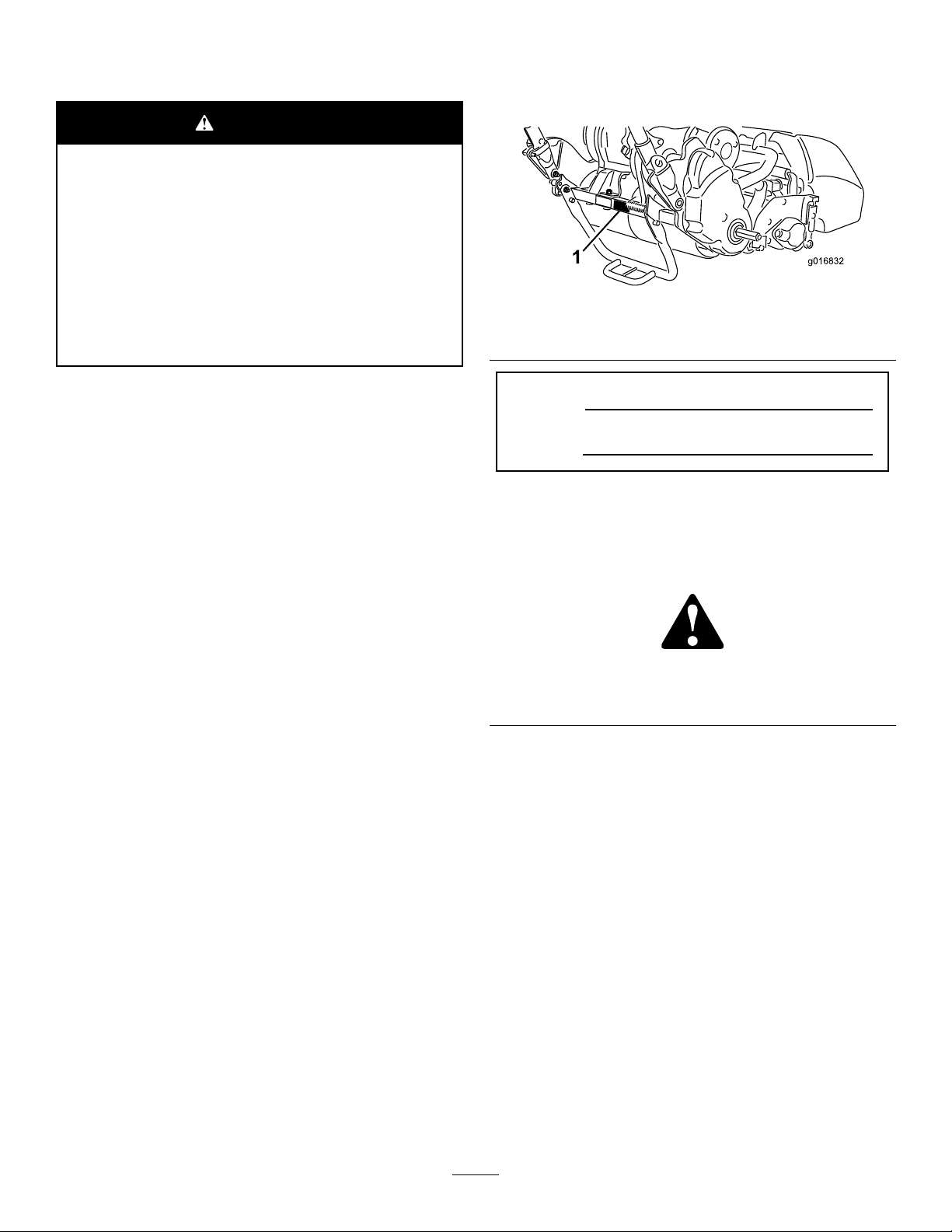
117–2718
130-8322
1.Onlyusegasolinethat
contains10%ethanolby
volume(E10)orless.
2.ReadtheOperator's
Manual.
3.Donotusegasolinethat
containsmorethan10%
ethanolbyvolume(E10).
decal117-2718
decal120-9598
120-9598
1.Brake4.Parkingbrake
decal130-8322
2.Releasehandleto
disengagethebrake.
3.Compressthehandleto
engagethebrake.
5.Rotatethelatchtolockthe
parkingbrake;compress
thehandletoreleasethe
latch.
120-9571
1.Lowerthelevertodisengagethetraction.
120-9570
1.Warning—stayawayfrommovingparts,keepallguards
andshieldsinplace.
decal120-9571
decal120-9570
decal131-311 1
131-3111
1.Fast
2.Slow
7
Page 8
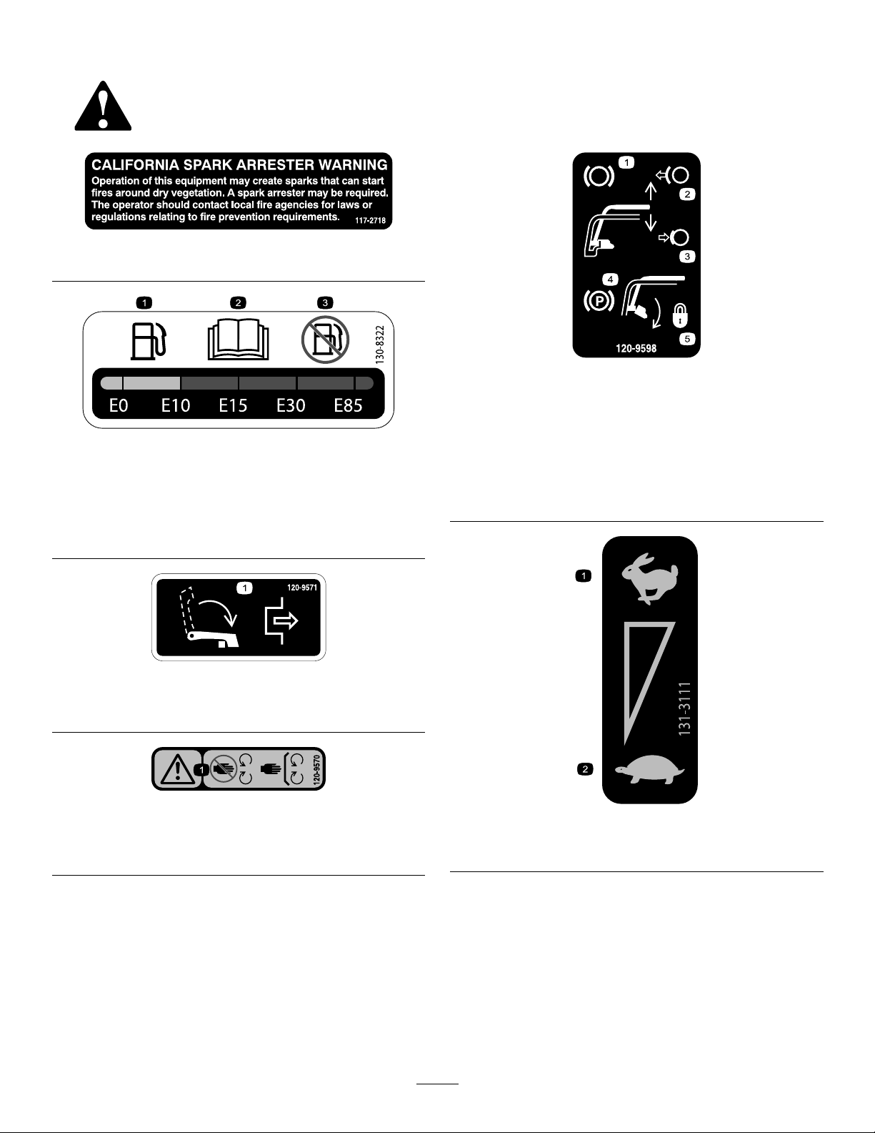
decal120-2769
120–2769
1.Toxicgasinhalation
hazard—donotoperate
indoors.
4.Warning—disconnectthe
spark-plugwireandread
theinstructionbefore
servicingorperforming
maintenance.
2.Explosionhazard—shut
offtheengineandkeep
awayfromopenames
5.Hotsurface/burn
hazard—donottouch
hotsurfaces.
whenrefueling.
3.Warning—shutoffthe
engineandturnoffthe
fuelbeforeleavingthe
machine.
6.Warning—readthe
Operator’sManual;when
addingfueltothetank,
onlylltothebottomof
thelltube.
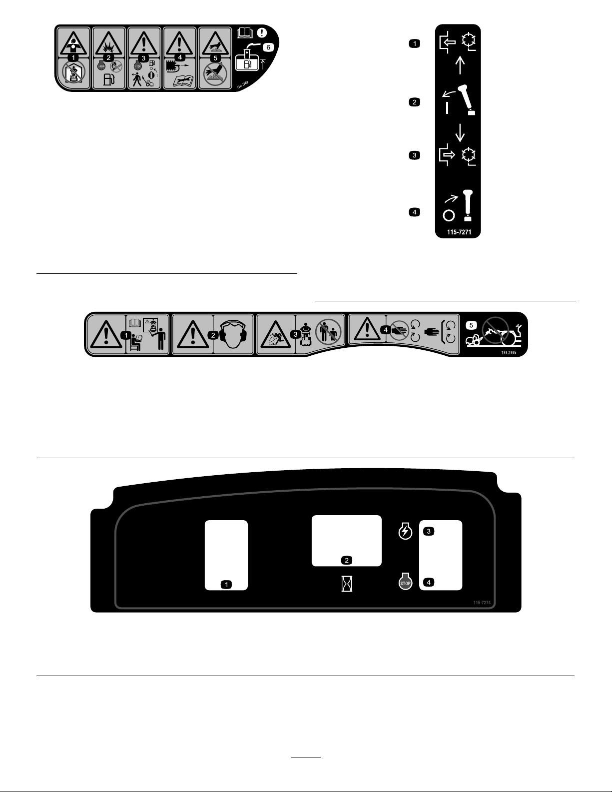
1.Warning—readtheOperator’sManual;
donotoperatethemachineunlessyou
aretrained.
2.Warning—wearhearingprotection.
1.Engagethereel.3.Disengagethereel.
2.Engagethelever .4.Disengagethelever.
133–2335
3.Thrownobjecthazard—keep
bystandersasafedistancefromthe
machine.
4.Warning—stayawayfrommoving
parts;keepallguardsandshieldsin
place.
decal115-7271
115-7271
decal133-2335
5.Donottowthemachine.
1.Lights(optional)
2.Hourmeter
decal115-7274
115-7274
3.Engine—start
4.Engine—shutoff
8
Page 9

Setup
LooseParts
Usethechartbelowtoverifythatallpartshavebeenshipped.
ProcedureDescription
1
2
3
4
5
6
MediaandAdditionalParts
Description
Operator'sManual
EngineOperator'sManual
PartsCatalog
OperatorTrainingMaterial
CerticateofCompliance
Nopartsrequired
Bolt,3/8x3/4inch
Handleretainer2
Hairpincotter2
Transportwheels(OptionalTransport
WheelKit,Model04123)
Nopartsrequired
Grassbasket
Qty.
1
1
1
1
1
Readorviewthesematerialsbeforeoperatingthe
machine.
Qty.
–
2Installthecuttingunittothetractionunit.
2Installthetransportwheels.
–
1Installthegrassbasket.
Preparethetractionunit(optional).
Installthehandleretainers.
Checktheengine-oillevel.
Use
Use
9
Page 10
Note:Determinetheleftandrightsidesofthe
G018142
1
2
3
machinefromthenormaloperatingposition.
1
PreparingtheTractionUnit
Optional
NoPartsRequired
2
InstallingtheCuttingUnit totheTractionUnit
Partsneededforthisprocedure:
2
Bolt,3/8x3/4inch
Procedure
Procedure
Ifyouareinstallingcuttingunit04251,02452,04253,
or04254onthistractionunit,completethefollowing
steps:
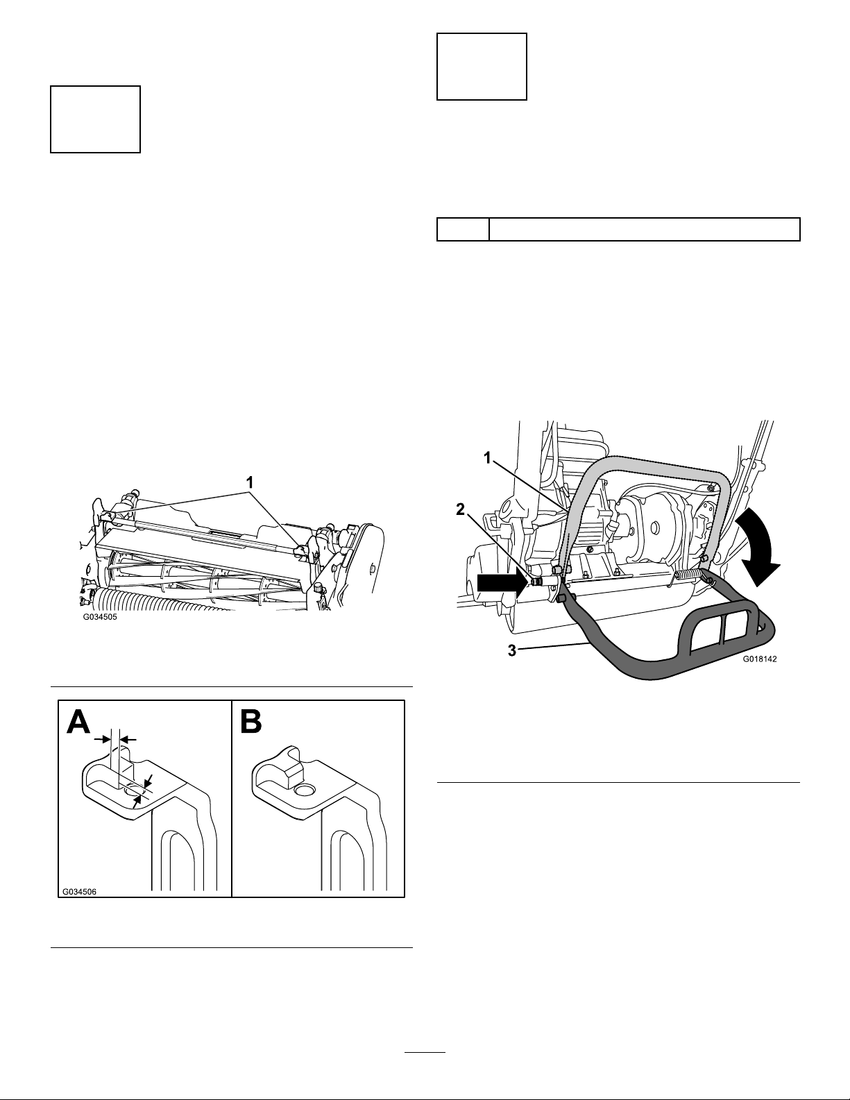
1.Positionthecuttingunitonaat,levelsurface.
2.Onbothpitcharms(Figure3),measure2.28
mm(0.09inch)inonthetabsandgrinddown
thecornerasshowninFigure4.
Figure3
1.Pitcharms
1.Placethemachineonitsdrumsonalevel
surface.
2.Lowerthekickstandandpushinthelocking
pintolockthekickstandintheserviceposition
(Figure5).Allowthemachinetorestonthe
lockingpin.
g034505
g018142
Figure5
1.Kickstand—storage
position
2.Lockingpin
3.Pushthecuttingunitunderthetractionunitand
tothelefttoengagethetransmissioncoupling
(Figure6).
g034506
3.Painttherevealedmetaltopreventcorrosion.
Figure4
10
3.Kickstand—service
position
Page 11
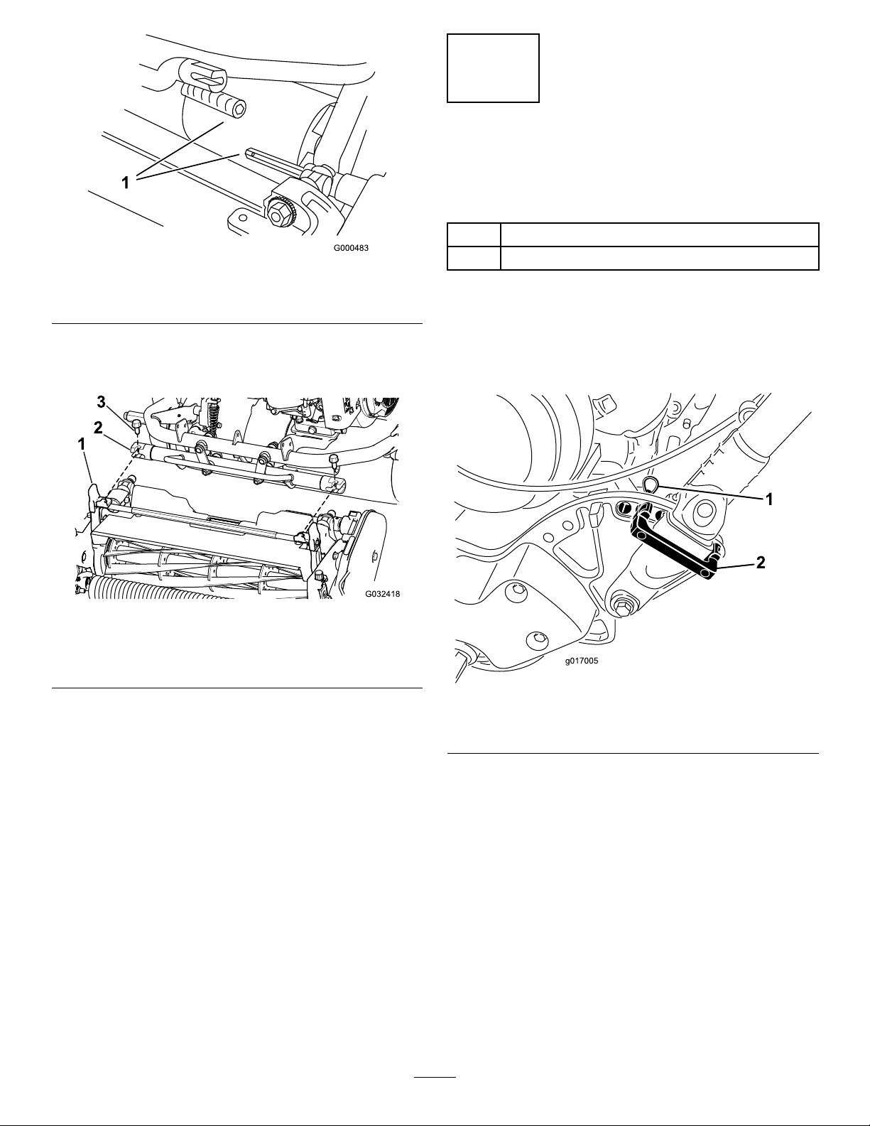
Figure6
3
InstallingtheHandle Retainers
Partsneededforthisprocedure:
2Handleretainer
g000483
2Hairpincotter
1.Transmissioncoupling
4.Maneuverthetractionunitframe(Figure7)
forwarduntilitengagesthecuttingunitpivot
arms.
Figure7
1.Cuttingunitpivotarms
2.Tractionunitframe
5.Securethetractionunitframetothecuttingunit
pivotarmswith2bolts(3/8x3/4inch)(Figure7).
3.Bolts
Procedure
1.Whilesupportingthehandle,removethecable
tiessecuringthehandleclampstotheside
plates(Figure8).
g032418
g017005
Figure8
1.Hairpincotter2.Handleretainer
Note:Toremovethecuttingunit,justloosen
the2bolts(3/8x3/4inch)approximately1-1/2
turnsandrotatethepivotarmsout.
6.Pushdownonthekickstandtoreleasethe
spring-loadedlockingpinandallowthekick
standtorotateuptothestorageposition.
2.Pivotthehandletothedesiredoperating
position,insertahandleretaineroverthehandle
clampandintothematchingholesintheside
plate(Figure8).
3.Securetheclampinpositionwithahairpincotter
(Figure8).
4.Repeattheprocedureontheoppositesideof
thehandle.
5.Adjustthehandleheighttothedesiredposition;
refertoAdjustingtheHandleHeight(page20).
Note:Themachineisshippedwiththe
handleadjustedtothelowestposition.The
machineistraditionallyoperatedwiththehandle
telescopedouttoitsmaximumheight.
11
Page 12
4
InstallingtheTransport
Wheels
Partsneededforthisprocedure:
Transportwheels(OptionalTransportWheelKit,
2
Model04123)
Procedure
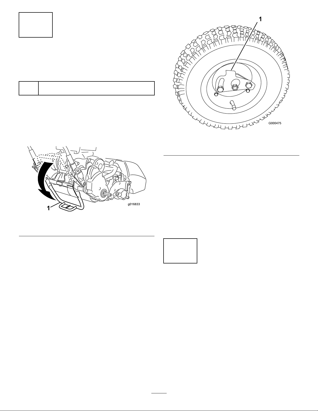
1.Pushthekickstanddownwithyourfootinthe
centerofthekickstandandpulluponthe
lowercentermachinehandleuntilthekickstand
hasrotatedforward,overcenter(Figure9).
g000475
Figure10
1.Lockingclip
3.Rotatethewheelbackandforthuntilitslides
completelyontotheaxleandthelockingclipis
securedinthegrooveontheaxleshaft.
Figure9
1.Kickstand
2.Pressthewheellockingcliptowardthecenter
ofwheelandslidethewheelontothehexshaft
(Figure10).
4.Repeattheprocedureontheoppositesideof
themachine.
5.Inatethetiresto83to103kPa(12to15psi).
g016833
6.Carefullylowerthemachineoffthekickstand
bypushingforwardslowlyorbyliftingthelower
centerhandlesupport,allowingthekickstandto
springbacktoitsnormalposition.
5
CheckingtheEngine-Oil Level
NoPartsRequired
Procedure
Checktheengine-oillevel,refertoCheckingthe
Engine-OilLevel(page28).
12
Page 13

6
InstallingtheGrassBasket
Partsneededforthisprocedure:
1
Grassbasket
Procedure
1.Graspthebasketbythehandle(Figure11).
Figure11
1.Baskethooks
2.Guidethebasketlipbetweenthecuttingunit
sideplatesandoverthefrontroller(Figure1 1).
g032408
Figure12
1.Pitcharmcontactpoint
g032407
3.Installthebaskethooksovertheframeloop
(Figure11).
Important:Ifyoueverdropthebasket,examine
thepitcharmcontactpointsnearthelowerlip
ofthebasketfordamage(Figure12).Straighten
thembeforeusingthebasket.Usingthebasket
withbentpitcharmcontactpointsmaycause
contactbetweenthebasketandreelcausing
undesirednoiseand/ordamagetothebasketand
reel.
13
Page 14

ProductOverview
ThrottleControl
Thethrottlecontrol(Figure14andFigure15)is
locatedontheright,rearsideofthecontrolpanel.
Rotatethethrottletoregulatetheenginespeed.
g032409
Figure13
1.Tractionandreel-drive
engagementlever
2.Operator-presencecontrol7.Grassbasket
3.Handle
4.Servicebrake
5.Controlpanel
Controls
6.Fueltank
8.Cuttingunit
9.Transportwheelaxle
Figure15
1.Fullspeed
2.Slowspeed
TractionandReel-Drive
EngagementLever
Thetractionandreel-driveengagementlever(Figure
16)islocatedonthefrontrightsideofthecontrol
panel.Fortransportoperation,theleverhas2
positions:NEUTRALandFORWARD.Pushingthelever
forwardengagesthetractiondrive.
Note:Tomovetheleveryoumustrstengagethe
operator-presencecontrol.
g027738
Figure14
1.Openspaceforoptional
lights
2.Parking-brakelatch
3.Servicebrake
4.Handle8.Tractionandreel-drive
5.Operator-presencecontrol
6.On/offswitch
7.Throttlecontrol
engagementlever
g032410
14
Page 15

ServiceBrake
Theservicebrake(Figure17)islocatedontheleft
frontsideofthehandle.Pullingtheleverbackwill
applytheservicebrake.Y oumustreleasethebrake
beforeyouengagethetractiondrive.
Figure16
1.NEUTRAL3.Tractiondrive-engaged
2.Tractiondriveneutraland
reeldriveoff
(transport)
4.Tractiondriveandreel
driveengaged
Forreeloperation,theleverhas2positions:ENGAGE
andDISENGAGE.Movethetopofthelevertotheleft
thenforwardtoengagethereelandbeginmowing.
Pushthelevertotherighttodisengagethereel
andcontinueforwardmotionorpullbackonitto
disengageboththereelandthetractiondrive.
Note:Ifyoureleasetheoperator-presencecontrol,
theleverreturnstoneutralandthemachinestops.
g000494
1.Parking-brakelatch
Figure17
2.Servicebrake
g016853
Parking-BrakeLatch
Theparking-brakelatch(Figure17)isusedwiththe
servicebrake.Withtheservicebrakeengaged,rotate
theparking-brakelatchtowardthebrakehandleand
releasetheservicebrakeontothelatchtoholdthe
servicebrakeinplace.Pullthebrakelevertorelease
it.
On/OffSwitch
Theon/offswitch(Figure14)islocatedontopofthe
controlpanel.MovetheswitchtotheONpositionto
starttheengineandOFFtoshutofftheengine.
Operator-PresenceControl(OPC)
Theoperator-presencecontrol(Figure14)mustbe
engagedbeforeengagingthetractionlever.Releasing
theOPCduringoperationreturnsthemachineto
neutralbutdoesnotshutofftheengine.
15
Page 16

ChokeLever
g018267
g018268
Recoil-StarterHandle
Thechokelever(Figure18)islocatedontheengine.
Theleverhas2positions:RUNandCHOKE.Movethe
chokelevertothehalf-openpositionwhenstartinga
coldengine.Aftertheenginestarts,movethelever
totheRUNposition.
g018267
Figure18
1.ChokeleverintheCHOKEposition
Fuel-ShutoffValve
Thefuel-shutoffvalve(Figure19)islocatedonthe
engine.Thevalvehas2positions:CLOSEDandOPEN.
MovethelevertotheCLOSEDpositionwhenstoringor
transportingmachine.Openthevalvebeforestarting
theengine.Thefuelcupislocatedbelowtheshutoff
valve.
Pulltherecoil-starterhandle(Figure20)tostartthe
engine.
g018268
Figure20
1.Recoil-starterhandle
Kickstand
Thekickstand(Figure22)ismountedtotherearofthe
machineandisusedtoraisetherearofthemachine
forinstallingorremovingthetransportwheelsandfor
preventingthemachineforfallingontothehandle
whenyouremovethereel.
•Tousethekickstandtoinstallthetransportwheels,
lowerittothegroundandstepdownonthe
kickstandloopwhilepullingupandbackonthe
lowercentermachinehandle(Figure21).
1.Fuel-shutoffvalvein
closedposition
CAUTION
Themachineisheavyandcancauseback
strainifliftedimproperly.
Putfootpressuredownonlyonthe
kickstandloopandonlyusethelower
centermachinehandletoraisetheunit.
Attemptingtoraisetheunitontothe
kickstandanyotherwaycancauseinjury.
g016847
Figure19
2.Fuelcup
16
Page 17

g018793
G018142
1
2
3
Figure23
g018142
Figure21
1.Lowercentermachine
handle
2.Kickstandloop
Figure22
1.Kickstand2.Kickstandloop
1.Kickstand—STORAGE
position
2.Lockingpin
g018793
g016833
3.Kickstand—SERVICE
position
•Topreventtheunitfromtippingbackwardwhen
removingthereel,lowerthekickstandandpush
inthelockingpintolockitintheSERVICEposition
(Figure23).
17
Page 18

Specications
G009027
1
2
1820TractionUnit
Width
Height
Lengthwithbasket
NetWeight(with11
bladecuttingunit
andgrassbasket
installed)
Widthofcut46cm(18inches)
Heightofcut1.5to7.5mm(1/16to19/64inches)
ClipfrequencyAdjustable(refertoCuttingUnit
82.5cm(32-1/2inches)
104.8cm(41–1/4inches)
152.4cm(60inches)
117kg(258lb)
withMicro-Cutbedknife
Operator’sManual)
Operation
Note:Determinetheleftandrightsidesofthe
machinefromthenormaloperatingposition.
ThinkSafetyFirst
Carefullyreadallsafetyinstructionsandsymbolsin
thesafetysection.Knowingthisinformationcould
helpyouorbystandersavoidinjury.
CAUTION
Thismachineproducessoundlevelsthatcan
causehearinglossthroughextendedperiods
ofexposure.
2120TractionUnit
Width
Height
Lengthwithbasket
NetWeight(with11
bladecuttingunit
andgrassbasket
installed)
Widthofcut53.3cm(21inches)
Heightofcut1.5to7.5mm(1/16to19/64inches)
ClipfrequencyAdjustable(refertoCuttingUnit
90.1cm(35-1/2inches)
104.8cm(41–1/4inches)
152.4cm(60inches)
117.9kg(260lb)
withMicro-Cutbedknife
Operator’sManual)
Wearhearingprotectionwhenoperatingthis
machine.
g009027
Figure24
1.Weareyeprotection.2.Wearhearingprotection.
CheckingtheEngine-Oil Level
Attachments/Accessories
AselectionofToroapprovedattachmentsand
accessoriesisavailableforusewiththemachineto
enhanceandexpanditscapabilities.Contactyour
AuthorizedServiceDealerorDistributororgoto
www.T oro.comforalistofallapprovedattachments
andaccessories.
Tobestprotectyourinvestmentandmaintainoptimal
performanceofyourToroequipment,countonToro
genuineparts.Whenitcomestoreliability,T oro
deliversreplacementpartsdesignedtotheexact
engineeringspecicationofourequipment.Forpeace
ofmind,insistonTorogenuineparts.
Checktheengine-oillevelbeforeeachuseorevery
8operatinghours,refertoCheckingtheEngine-Oil
Level(page28).
FillingtheFuelTank
Thefueltankcapacityis3.0L(0.79gallons).
•Forbestresults,useonlyclean,fresh(lessthan
30daysold),unleadedgasolinewithanoctane
ratingof87orhigher((R+M)/2ratingmethod).
•Ethanol:Gasolinewithupto10%ethanol
(gasohol)or15%MTBE(methyltertiarybutyl
ether)byvolumeisacceptable.Ethanoland
MTBEarenotthesame.Gasolinewith15%
ethanol(E15)byvolumeisnotapprovedforuse.
Neverusegasolinethatcontainsmorethan
10%ethanolbyvolume,suchasE15(contains
15%ethanol),E20(contains20%ethanol),orE85
(containsupto85%ethanol).Usingunapproved
gasolinemaycauseperformanceproblemsand/or
enginedamagewhichmaynotbecoveredunder
warranty.
18
Page 19

•Donotusegasolinecontainingmethanol.
•Donotstorefueleitherinthefueltankorfuel
containersoverthewinterunlessafuelstabilizer
isused.
•Donotaddoiltogasoline.
DANGER
Incertainconditions,gasolineisextremely
ammableandhighlyexplosive.Areor
explosionfromgasolinecanburnyouand
othersandcandamageproperty.
•Fillthefueltankoutdoors,inanopenarea,
whentheengineiscold.Wipeupany
gasolinethatspills.
DANGER
Incertainconditionsduringfueling,static
electricitycanbereleasedcausingaspark
whichcanignitethegasolinevapors.Are
orexplosionfromgasolinecanburnyouand
othersandcandamageproperty.
•Alwaysplacegasolinecontainersonthe
groundawayfromyourvehiclebefore
lling.
•Donotllgasolinecontainersinsidea
vehicleoronatruckortrailerbedbecause
interiorcarpetsorplastictruckbedliners
mayinsulatethecontainerandslowthe
lossofanystaticcharge.
•Neverllthefueltankinsideanenclosed
trailer.
•Donotllthefueltankcompletelyfull.Add
gasolinetothefueltankuntilthelevelis6
to13mm(1/4to1/2inch)belowthebottom
ofthellerneck.Thisemptyspaceinthe
tankallowsgasolinetoexpand.
•Neversmokewhenhandlinggasoline,and
stayawayfromanopenameorwhere
gasolinefumesmaybeignitedbyaspark.
•Storegasolineinanapprovedcontainer
andkeepitoutofthereachofchildren.
Neverbuymorethana30-daysupplyof
gasoline.
•Donotoperatewithoutentireexhaust
systeminplaceandinproperworking
condition.
•Whenpractical,removegas-powered
equipmentfromthetruckortrailerand
refueltheequipmentwithitswheelsonthe
ground.
•Ifthisisnotpossible,thenrefuelsuch
equipmentonatruckortrailerfroma
portablecontainer,ratherthanfroma
gasolinedispensernozzle.
•Ifagasolinedispensernozzlemustbe
used,keepthenozzleincontactwiththe
rimofthefueltankorcontaineropeningat
alltimesuntilfuelingiscomplete.
WARNING
Gasolineisharmfulorfatalifswallowed.
Long-termexposuretovaporscancause
seriousinjuryandillness.
•Avoidprolongedbreathingofvapors.
•Keepfaceawayfromnozzleandgastank
orconditionerbottleopening.
•Avoidcontactwithskin;washoffspillage
withsoapandwater.
1.Cleanaroundthefuel-tankcapandremovethe
capfromthetank(Figure25).Usingunleaded
gasoline,llthefueltanknohigherthantothe
bottomofthelterscreen.Donotoverll.
19
Page 20

g018269
Figure25
1.Fuel-tankcap
2.Installthefuel-tankcapandwipeupanyspilled
gasoline.
AdjustingtheHandleAngle
1.Removethehairpincottersfromthehandle
retainersoneachsideofthemachine(Figure
27).
g018269
AdjustingtheHandle Height
Note:Themachineisshippedwiththehandle
adjustedtothelowestposition.Themachineis
traditionallyoperatedwiththehandletelescopedout
toitsmaximumheight.
1.Loosenthe3carriageboltsandnutssecuring
eachsideofthehandleinthehandleclamps
(Figure26).
g017005
Figure27
1.Hairpincotter2.Handleretainer
2.Whilesupportingthehandle,removethehairpin
cottersfromeachsideandpivotthehandleto
thedesiredoperatingposition(Figure27).
3.Installthehandleretainersandhairpincotters.
AdjustingtheThrottle Control
1.Removetheconsolecover.
2.Loosenthe2fastenerssecuringthethrottle
control(Figure28).
Figure26
1.Handleclamp
2.Nut
2.Pulluponthehandleslowlyandevenlyoneach
sideuntilitisinthedesiredoperatingposition.
3.Tightenthecarriageboltsandnutstolockthe
adjustment.
3.Carriagebolts
g016851
20
Page 21

Figure28
1.Fasteners2.Throttlecontrol
3.Adjustthethrottlecontroltothedesiredposition.
ShuttingOfftheEngine
1.Movethetractionandreeldrivecontrolsto
theDISENGAGEDposition,thethrottlecontrolto
SLOW,andtheon/offswitchtoOFF.
2.Pullthemoldedspark-plugwireoffofthespark
plugtopreventthepossibilityofaccidental
startingbeforestoringthemachine.
3.Closethefuel-shutoffvalvebeforestoringor
transportingthemachineinavehicle.
TransportingtheMachine
g027739
Note:Donotruntheenginewhiletransportingitin
atransporttrailerbecausedamagecanoccurtothe
machine.
Iftheoptionaltransportwheelsarenotgoingtobe
installed,proceedtostep4.
4.Tightenthethrottle-controlfasteners.
5.Installthepreviouslyremovedconsolecover.
StartingandShuttingOff theEngine
Note:Forillustrationsanddescriptionsofthecontrols
referencedinthissection,refertoControls(page14).
StartingtheEngine
Note:Ensurethatthespark-plugwireisinstalledon
thesparkplug.
1.Ensurethatthetractionandreel-driveleversare
intheDisengagedposition.
Note:Theenginewillnotstartifthetraction
leverisintheengagedposition.
2.Movetheon/offswitchtotheONposition.
3.MovethethrottlecontroltotheFASTposition.
4.Openthefuel-shutoffvalveontheengine.
5.Movethechokelevertothehalf-openposition
whenstartingacoldengine.Thechokemaynot
berequiredwhenstartingawarmengine.
6.Pulltherecoilstarterhandleoutuntilpositive
engagementresults,thenpullitvigorouslyto
starttheengine.Openthechokeastheengine
warmsup.
Important:Donotpulltherecoilropeto
itslimitorletgoofthestarterhandlewhen
theropeispulledoutbecausetherope
maybreakortherecoilassemblymaybe
damaged.
1.Pushthekickstanddownwithyourfootandpull
uponthehandlesupportuntilthekickstandhas
rotatedforward,overcenter.
2.Installthetransportwheels.
3.T oreleasethekickstand,pulluponthehandle
andlowertherearofthemachineontothe
transportwheels.
4.Ensurethatthetractionandreeldrivecontrols
areintheDISENGAGEDpositionandstartthe
engine.
5.SetthethrottlecontroltoSLOW,tipthefrontof
themachineup,graduallyengagethetraction
drive,andslowlyincreasetheenginespeed.
6.Adjustthethrottletooperatethemachineat
thedesiredgroundspeedandtransportthe
machinetothedesireddestination.
PreparingtoMow
1.Returnthetractioncontrollevertothe
DISENGAGEDposition,thethrottletotheSLOW
position,andshutofftheengine.
2.Pushthekickstanddownwithyourfootandpull
uponthehandlesupportuntilthekickstandhas
rotatedforward,overcenter.
3.Removethetransportwheels.
4.Carefullylowerthemachineoffthekickstand.
Ensurethatthemachineiscarefullyadjustedandthat
itissetevenlyonbothsidesofthereel.Improper
machineadjustmentismagniedintheappearance
oftheclippedturf.Removeallforeignobjectsfrom
theturfpriortomowing.Makesurethateveryone,
21
Page 22

especiallychildrenandpets,areclearofthework
area.
MowingTips
Important:Grassclippingsactasalubricant
whenmowing.Excessiveoperationofthecutting
unitwiththeabsenceofgrassclippingscan
damagethecuttingunit.
•Thegreensshouldbemowedinastraightback
andforthdirectionacrossthegreen.
•Avoidcircularmowingorturningthemachineon
thegreensareastopreventscufng.
•Turningthemachineshouldbedoneoffthegreen
byraisingthecuttingreel(pushingthehandle
down)andturningonthetractiondrum.
•Mowingshouldbedoneatanormalwalkingpace.
Fastspeedssavesverylittletimeandresultsin
aninferiormowingjob.
•Toassistinmaintainingastraightlineacross
thegreenandtokeepthemachineanequal
distancefromtheedgeofthepreviouscut,usethe
alignmentstripesonthebasket(Figure29).
OperatingtheControlswhile
Mowing
1.Starttheengine,setthethrottletoareduced
speed,pushdownonthehandletoraisethe
cuttingunit,presstheoperator-presencecontrol,
movethetractionlevertotheENGAGEDposition
andtransportthemachineontothecollarofthe
green(Figure30).
2.MovethetractionlevertotheDISENGAGED
positionandengagethereel-drivelever(Figure
30).
Figure29
1.Alignmentstripes
OperatingtheMachineinLow
LightConditions
Whenoperatingthemachineinlowlightconditions,
usetheoptionalLEDLightKit,availablefromyour
AuthorizedT oroDistributor.
Important:Donotuseotherlightsystemswith
thismachineastheywillnotoperateproperlywith
theengineACoutput.
g000494
Figure30
1.Tractiondrive—neutral3.Tractiondrive—engaged
g016840
2.Tractiondriveneutraland
reeldriveoff
3.MovethetractionlevertotheENGAGEDposition,
increasethethrottlespeeduntilthemachineis
travelingatthedesiredgroundspeed,drivethe
machineoutontothegreenarea,lowerthefront
ofthemachinedown,andcommenceoperation
(Figure30).
(transport)
4.Tractiondriveandreel
driveengaged
OperatingtheControlsafter
Mowing
1.Driveoffthegreen,movethereeldriveand
tractioncontrolleverstotheDISENGAGED
position,andshutofftheengine.
22
Page 23

2.Emptythegrassbasketofclippings,installthe
grassbasketonthemachine,andcommence
thetransportoperation.
CheckingtheOperationof theInterlockSwitches
ServiceInterval:Beforeeachuseordaily
CAUTION
Ifthesafetyinterlockswitchesare
disconnectedordamaged,themachinecould
operateunexpectedly,causingpersonal
injury.
•Donottamperwiththeinterlockswitches.
•Checktheoperationoftheinterlock
switchesdailyandreplaceanydamaged
switchesbeforeoperatingthemachine.
CheckingtheOperator-Presence
Control(OPC)InterlockSwitch
4.WiththeOPCpressedandthetractionlever
engaged,releasetheOPC(Figure31).The
tractionlevershoulddisengage.Ifthetraction
leverdoesnotdisengage,theinterlocksystem
needsservice.Correcttheproblembefore
operating;refertoServicingtheTraction
InterlockSwitch(page31).
5.WiththeOPCpressedandtheshiftlevermoved
totheleft,engagethetractionandreeldrive,
releasetheOPC(Figure31).Thetractionlever
shoulddisengage.Ifthetractionleverdoesnot
disengage,theinterlocksystemneedsservice.
Correcttheproblembeforeoperating.;referto
ServicingtheTractionInterlockSwitch(page31)
orAdjustingtheReelControl(page35).
6.WiththeOPCpressedandtheshiftlevermoved
tothelefttoengagethetractionandreeldrive,
movetheshiftlevertotherighttodisengage
thereeldrive(Figure31).Thereeldriveshould
disengage.Ifthereeldrivedoesnotdisengage,
theinterlocksystemneedsservice.Correctthe
problembeforeoperating.;refertoAdjustingthe
ReelControl(page35).
7.Carefullylowerthemachineoffthekickstand.
1.Pushthekickstanddownwithyourfootandpull
uponthehandlesupportuntilthekickstandhas
rotatedforward,overcenter.
2.Starttheengine.
3.WiththeOPCreleased,attempttoengagethe
tractionlever(Figure31).Thetractionlever
shouldnotengage.Ifthetractionleverengages,
theinterlocksystemneedsservice.Correctthe
problembeforeoperating;refertoServicingthe
TractionInterlockSwitch(page31).
CheckingtheTractionInterlock
Switch
1.Pushthekickstanddownwithyourfootandpull
uponthehandlesupportuntilthekickstandhas
rotatedforward,overcenter.
2.WiththeOPCpressed,thetractionlever
engaged,andtheenginecontrolsinthestarting
position(Figure31).Attempttostarttheengine.
Theengineshouldnotstart.Iftheenginestarts,
theinterlockswitchneedsservice.Correctthe
problembeforeoperating.RefertoServicingthe
TractionInterlockSwitch(page31).
3.Carefullylowerthemachineoffthekickstand.
1.Operator-presencecontrol
(OPC)
2.Tractionlever
g032412
Figure31
3.Brakelever
23
Page 24

CheckingtheBrake-Interlock
Switch
1.Pushthekickstanddownwithyourfootandpull
uponthehandlesupportuntilthekickstandhas
rotatedforward,overcenter.
2.Withthetractionleverdisengaged,theservice
brakeengaged,andtheenginecontrolsin
thestartingposition(Figure31),attemptto
starttheengine.Theengineshouldstart.If
theenginedoesnotstart,theinterlockswitch
needsservice.Correcttheproblembefore
operatingthemachine;refertoServicingthe
Brake-InterlockSwitch(page32).
3.Withtheenginerunning,engagetheservice
brake(nottheparkingbrake),presstheOPC,
andengagethetractionlever(Figure31).The
engineshouldlabortoovercomethebrake
butshouldnotshutoff.Iftheengineshutsoff
immediately,theinterlockswitchneedsservice.
Correcttheproblembeforeoperatingthe
machine;refertoServicingtheBrake-Interlock
Switch(page32).
4.Withtheenginerunning,engagethe
parking-brakelatch,presstheOPC,andengage
thetractionlever(Figure31).Theengineshould
shutoff.Iftheenginedoesnotshutoff,the
interlockswitchneedsservice.Correctthe
problembeforeoperating;refertoServicingthe
Brake-InterlockSwitch(page32).
5.Carefullylowerthemachineoffthekickstand.
ReleasingtheTransmission
Ifthemachinebecomesdisabled,youcandisengage
thedrumfromthetransmissiontoallowthemachine
tobemaneuvered.
1.Ontherightrearcornerofthemachine,locate
thetractionengage/disengagelevernexttothe
drivehousingdrum(Figure32).
Figure32
1.Traction
engage/disengage
lever—engaged
2.Rotatetheleverrearwardtodisengagethe
transmissionfromthedrum.
2.Traction
engage/disengage
lever—disengaged
g032413
CAUTION
Notcarefullyrotatingthelevermay
causethespring-loadedlevertostrike
yourhand.
Carefullyrotatethelever.
3.Movethemachineasneeded.
Important:Ifpossible,donottowthe
machine.Ifitisabsolutelynecessary ,do
nottowatanyspeedgreaterthan4.8kph(3
mph);alwaysdisengagethetransmission
fromthedrum.Failingtodosowilllikely
damagethemachine.
4.Whennished,rotatetheleverforwardto
engagethetransmissiontothedrum.
Note:Thebrakeisstilloperationalwiththe
transmissiondisengagedfromthedrum.
24
Page 25

SettingtheMachinetoMatchTurfConditions
Usethefollowingtabletosetthemachinetomatchturfconditions.
Bedbars:StandardandOptional(Flex/eFlex2120Machines)
PartNumberDescriptionAggressiveness
106-2468-01Non-AggressiveLess
99-3794-03AggressiveMoreBlack
Bedbars:StandardandOptional(Flex/eFlex1820Mowers)
110-2282-01Non-AggressiveLess
110-2281-03AggressiveMoreBlack
Bedknives:StandardandOptional(Flex/eFlex2120Machines)
PartNumberDescription
115-1880Microcut-EdgeMax
93-4262Microcut
108-4303ExtendedMicrocut
115-1881Tournament-EdgeMax
93-4263T ournament
108-4302ExtendedTournament
93-4264
Bedknives:StandardandOptional(Flex/eFlex1820Machines)
117-1530Microcut-EdgeMax
98-7261Microcut
110-2300ExtendedMicrocut
98-7260T ournament
117-1532Tournament-EdgeMax
110-2301
LowCut6.4mm(0.25inch)andup
LowCut6.4mm(0.25inch)andup
Height-of-cutRangeComments
1.6to3.2mm(0.062to0.125inch)Standard
1.6to3.2mm(0.062to0.125inch)
1.6to3.2mm(0.062to0.125inch)
3.2to6.4mm(0.125to0.25inch)
3.2to6.4mm(0.125to0.25inch)
3.2to6.4mm(0.125to0.25inch)
1.6to3.2mm(0.062to0.125inch)Standard
1.6to3.2mm(0.062to0.125inch)
1.6to3.2mm(0.062to0.125inch)
3.2to6.4mm(0.125to0.25inch)
3.2to6.4mm(0.125to0.25inch)
Comments
Red,Standard
Red,Standard
Lessaggressive
Lessaggressive
Lessaggressive
Rollers(Flex/eFlex2120Machines)
PartNumberDescription
04255NarrowWiehle
04256WideWiehle
04257FullRoller
04258NarrowWiehle—Long
04267Paspalum
115-7356RearRoller
120-9595RearRoller
Rollers(Flex/eFlex1820Machines)
120-9607NarrowWiehle
120-9609WideWiehle
120-9611FullRoller
121-4681NarrowWiehle—Long
120-9605RearRoller
Diameter/MaterialComments
6.4cm(2.5inches)/Aluminum
6.4cm(2.5inches)/Aluminum
6.4cm(2.5inches)/Steel
6.4cm(2.5inches)/AluminumMoreedgesupport;4.3cm(1.7inches)longer
6.4cm(2.5inches)/AluminumLesspenetration,softenednarrowspacedgrooves
5.1cm(2.0inches)/AluminumStandardrear
5.1cm(2.0inches)/SteelSteelrear
6.4cm(2.5inches)/Aluminum
6.4cm(2.5inches)/Aluminum
6.4cm(2.5inches)/Steel
6.4cm(2.5inches)/AluminumMoreedgesupport;4.3cm(1.7inches)longer
5.1cm(2.0inches)/AluminumStandardrear
Narrowspacedgrooves
Morepenetration,widespacedgrooves
Leastpenetration
Narrowspacedgrooves
Morepenetration,widespacedgrooves
Leastpenetration
25
Page 26

Maintenance
Note:Determinetheleftandrightsidesofthemachinefromthenormaloperatingposition.
Important:WhenusingthemachineinconjunctionwiththeTransPro80,alwaysusethestopsonthe
trailerwhenservicingthemachine.Overtippingcanresultinfuelspillage.
ThestopontheRailRampKitrequiresabroomhandleorsimilaritemtobeinsertedthroughthe
holesbehindthewheels.
RecommendedMaintenanceSchedule(s)
MaintenanceService
Interval
Aftertherst20hours
Beforeeachuseordaily
Every50hours
Every100hours
Every500hours
Every1,000hours
Beforestorage
MaintenanceProcedure
•Changetheengineoil.
•Cleanthefuelcupandfuel-tankscreen.
•Checktheoperationoftheinterlockswitches.
•Checktheengine-oillevel.
•Changetheengineoil.
•Cleantheaircleaner(moreoftenindirtyordustyconditions).
•Replacethepaperairlterelement(moreoftenindirtyordustyconditions).
•Checkthesparkplug.
•Cleanthefuelcupandfuel-tankscreen.
•Replacetheclutchoil.
•Cleanthecarburetor.
•Inspecttheintakeandexhaustvalves.Adjustasnecessary.
•Replacethefuelline.
•Inspectthereel-drivebelt.
•Inspectthetransmissionbearingsandreplaceasnecessary.
•Paintchippedsurfaces.
Important:Refertoyourengineowner'smanualforadditionalmaintenanceprocedures.
26
Page 27

DailyMaintenanceChecklist
Important:Duplicatethispageforroutineuse.
Maintenance
CheckItem
Checkthe
safetyinterlock
operation.
Checkthe
parkingbrake
operation.
Checkthatpivot
jointsoperate
freely.
Checkthefuel
level.
Checktheengine
oillevel.
Checktheair
lter.
Cleantheengine
coolingns.
Checkfor
unusualengine
noises.
Checkfor
unusual
operatingnoises.
Checkthe
reel-to-bedknife
adjustment.
Checkthe
height-of-cut
adjustment.
Touchup
damagedpaint.
Fortheweekof:
Mon.Tues.Wed.Thurs.Fri.
Sat.Sun.
NotationforAreasofConcern
Inspectionperformedby:
ItemDate
Information
27
Page 28

EngineMaintenance
g018270
1
2
ServicingtheEngineOil
Fillthecrankcasewithapproximately0.6L(20
oz)oftheproperviscosityoilbeforestarting.Use
ahigh-qualityoilhavingtheAmericanPetroleum
Institute(API)serviceclassicationSEorhigher.
Selecttheproperoilviscosity(weight)basedon
theambienttemperature.Figure33illustratesthe
temperature/viscosityrecommendations.
g018270
Figure34
Figure33
Note:Usingmulti-gradeoils(5W-20,10W-30and
10W-40)willincreaseoilconsumption.Checktheoil
levelmorefrequentlywhenusingthem.
CheckingtheEngine-OilLevel
ServiceInterval:Beforeeachuseordaily
Note:Thebesttimetochecktheengineoiliswhen
theengineiscool,beforeithasbeenstartedforthe
day.Ifithasalreadybeenrun,allowtheoiltodrain
backdowntothesumpforatleast10minutesbefore
checking.IftheoillevelisatorbelowtheLmarkon
thedipstick,addoiltobringtheoilleveltotheHmark.
Donotoverll.IftheoillevelisbetweentheHand
Lmarks,donotaddoil.
1.Oil-levelgauge
3.Removetheoil-levelgaugebyrotatingit
counterclockwise(Figure34).
4.Wipetheoil-levelgaugecleanandinsertitinto
thellerport.Donotscrewthegaugeintothe
port.Thenremoveitandcheckthelevelofthe
oil.Ifthelevelislow,addonlyenoughoilto
g016841
raisetheleveluntilitisbetweentheHandL
marksonthegauge(Figure35).Checkthelevel
oftheoil.Donotoverll.
5.Installtheoil-levelgaugeandwipeupany
spilledoil.
2.Drainplug
g007620
Figure35
1.Removethetransportwheels(ifinstalled).
2.Positionthemachinesothattheengineislevel
andcleanaroundtheoil-levelgauge(Figure34).
ChangingtheEngineOil
ServiceInterval:Aftertherst20hours
Every50hours
1.Startandruntheengineforafewminutesto
warmtheengineoil.
2.Attherearofthemachine,placeadrainpan
underthedrainplug(Figure34).Loosenthe
drainplug.
3.Pushdownonthehandletotipthemachineand
enginebackward,allowingalltheoiltoruninto
thedrainpan.
28
Page 29

4.Installthedrainplugandrellthecrankcase
g018271
1
withthespeciedoil.
5.Wipeupanyspilledoil.
6.Disposeoftheusedoilproperly .Recycle
accordingtolocalcodes.
ServicingtheAirCleaner
ServiceInterval:Every50hours
1.Disconnectthewirefromthesparkplug.
2.Removethewingnutsecuringtheair-cleaner
covertotheaircleanerandremovethecover.
Cleanthecoverthoroughly(Figure36and
Figure37).
g016845
Figure37
Figure36
1.Air-cleanercover
3.Ifthefoamelementisdirty,removeitfromthe
paperelement(Figure37).Cleanitthoroughly.
A.Washthefoamelementinasolutionof
liquidsoapandwarmwater.Squeezeitto
removethedirt,butdonottwistitbecause
thefoammaytear.
B.Drybywrappinginacleanrag.Squeeze
theragandfoamelementtodry,butdonot
twistbecausethefoammaytear.
C.Saturatetheelementwithcleanengineoil.
Squeezetheelementtoremovetheexcess
oilandtodistributetheoilthoroughly.
Note:Anelementdampwithoilis
desirable.
1.Wingnut4.Foamelement
2.Air-cleanercover5.Paperelement
3.Wingnut6.Air-cleanerbase
g018271
4.Whenservicingthefoamelement,checkthe
conditionofthepaperelement.Replaceas
required.
Note:Donotusecompressedairtocleanthe
paperelement.
5.Installthefoamelement,paperelement,and
air-cleanercover.
Important:Donotoperatetheengine
withouttheair-cleanerelementbecause
extremeenginewearanddamagewillresult.
29
Page 30

ServicingtheSparkPlug
g018272
1
FuelSystem
ServiceInterval:Every100hours
UseanNGKBR6HSsparkplugorequivalent.The
correctairgapis0.6to0.7mm(0.024to0.028inch).
1.Pullthemoldedwireoffthesparkplug(Figure
38).
Figure38
Maintenance
CleaningtheFuelCupand Fuel-TankScreen
ServiceInterval:Aftertherst20hours
Every100hours/Monthly(whichevercomes
rst)
1.Closethefuelshutoffvalveandunscrewthe
fuelcupfromthelterbody(Figure40).
Note:A17mm,12pointsockettsoverthe
bodyofthefuelcupandaidsintheremoval.
g018272
1.Spark-plugwire
2.Cleanaroundthesparkplugandremovethe
plugfromthecylinderhead.
Important:Replaceacracked,fouled,or
dirtysparkplug.Donotsandblast,scrape,
orcleantheelectrodesbecauseengine
damagecouldresultfromgritenteringthe
cylinder.
3.Settheairgapat0.6to0.7mm(0.024to0.028
inch)asshowninFigure39.Installthecorrectly
gappedsparkplugandtightenitrmlyto23
N∙m(17ft-lb).
Figure40
1.Shutoffvalve
2.Cleanthefuelcupincleanfuelandinstallit.
3.Unscrewandremovethefuel-tankcapfromthe
fueltank(Figure41).
2.Fuelcup
g016847
1.Center-electrodeinsulator
2.Sideelectrode
Figure39
3.Airgap—0.6to0.7mm
(0.024to0.028inch)
g016950
g016857
Figure41
1.Fuel-tankcap2.Fuel-tankscreen
30
Page 31

4.Removethefuel-tankscreenfrominsidethe
fueltank.
ElectricalSystem
5.Cleanthescreenincleanfuelandinstallitin
thetank.
6.Installthefuel-tankcaptothefueltank.
ReplacingtheFuelLine
ServiceInterval:Every1,000hours
Iffuelleaksfromtheline,replaceitimmediately.
Maintenance
ServicingtheTraction InterlockSwitch
Usethefollowingprocedureiftheswitchneeds
adjustmentorreplacement.
1.Makesurethattheengineisoff.
2.Removethecontrolpanel.
3.Engagethetractionlever.
Figure42
1.Tractionlever2.Interlockswitch
4.Loosentheinterlockswitchmountingfasteners
(Figure42).
5.Placea1.6mm(0.062inch)thickshimbetween
thetractionleverandtheinterlockswitch(Figure
42).
6.Tightentheinterlockswitchmountingfasteners.
7.Engagethetractionleverandcheckthegap.
Thenormaloperatingrangeisbetween0.76to
3.05mm(0.03to0.12inch).Withthetraction
leverengaged,verifythattheswitchloses
continuity.Replacetheswitchifrequired.
g016912
31
Page 32

Servicingthe
3
Brake-InterlockSwitch
BrakeMaintenance
1.Makesurethattheengineisoff.
2.Removethecontrolpanel.
3.Engagetheservice-brakeleverandengagethe
parking-brakelatch.
4.Loosentheinterlockswitchmountingfasteners
(Figure43).
Adjustingthe Service/ParkingBrake
Iftheservice/parkingbrakeslipswhenoperated,
adjustthecableasfollows:
1.Movetheservice/parkingbrakelevertotheOFF
position.
2.Removethecontrolpanel.
3.T oincreasethecabletension,loosentheupper
cablejamnutandtightenthelowercablejam
nut(Figure44)untilaforceof156N(35lb)
appliedtothebrakeleverhandleisrequiredto
releasetheparking-brakelatch.Donotover
adjustitorthebrakebandmaydrag.
Figure43
1.Parking-brakelatch
2.Interlockswitch
5.Placea1.6mm(0.062inch)thickshimbetween
theparking-brakelatchandtheinterlockswitch
(Figure43).
6.Tighteninterlockswitchmountingfasteners.
Checkthegap.Thelatchmustnotcontactthe
switch.
7.Engagethebrakeleverandrotatethelatch.
Verifythattheswitchlosescontinuity.Replace
theswitchifrequired.
3.Service-brakelever
g016913
g016920
Figure44
1.Jamnuts
2.Service-brakecable
32
Page 33

BeltMaintenance
g018273
InspectingtheReel-Drive Belt
D.Makesurethatthecompressionspringis
applyingthepropertensiononthebelt.
E.Tightenthebearinghousingmountingnut.
F.Installthebeltcover.
ServiceInterval:Every1,000hours
1.Loosentheangeboltsecuringthebeltcover
andremovethebeltcovertoexposethebelt
(Figure45).
Figure45
1.Beltcover
2.T oadjustthebelttension:
A.Loosenthebearinghousingmountingnut
(Figure46).
VisuallyInspectingtheReel Clutch
Removetherubberplug(Figure47)fromtheholein
thefrontofthetransmissiontovisuallyinspectthe
reelclutchwhenmakingadjustments.
Important:Replacetheplugwhennishedto
preventwateranddebrisfromcontaminatingthe
clutch.
g018273
Figure46
1.Bearinghousingmounting
nut
2.Reel-drivebelt
B.Usinga16mm(5/8inch)wrench,rotate
thebearinghousingtomakesurethatit
operatesfreely.
C.Cleananydebrisfrominsidethebelt
compartmentandfromaroundthe
compressionspring(Figure46).
3.Compressionspring
g016949
Figure47
1.Rubber-holeplug
g017116
2.Engage/disengageshaft
33
Page 34

Engaging/Disengaging
1
2
G019886
ControlsSystem
theTransmission-Belt
Tensioner
Thetransmissionbeltistensionedbyaspringloaded
idlerpulley.Ifyoumustengageordisengagethe
belttension,usea3/8inchwrenchtorotatethe
engage/disengageshaft(Figure47)tothedesired
position.Rotatingtheshaft1/4turnclockwise
disengagestheidlerfromthebelt(Figure48).
Note:Thebelttensionmustbedisengagedpriorto
removingthetransmissioncover.
Figure48
1.Engaged2.Disengaged
Maintenance
AdjustingtheTraction Control
ServiceInterval:Every500hours—Replacethe
clutchoil.
Ifthetractioncontroldoesnotengageorslipsduring
operation,thetractioncontrolmayneedadjusting.
1.MovethetractioncontroltotheENGAGED
position.
2.Measurethedistancefromthepinoneither
endofthetraction-controlspring(Figure49);if
itisnotwithin7.3to7.6cm(2-7/8to3inches),
adjusttheclutchaccordingtothestepsbelow.
g019886
g032417
Figure49
1.Measurethisdistance;
shouldbe7.3to7.6cm
(2-7/8to3inches)
2.Traction-controlspring5.Jamnut
3.Clevispin
A.Disengagethetraction-controllever.
B.Loosenthejamnutontheturnbuckleand
34
removetheclevispin,disconnectingthe
springfromtheturnbuckle(Figure49).
C.Turntheturnbuckleinorouttoadjustthe
lengthasneeded.
4.Turnbuckle
Page 35

D.Installtheturnbuckletothespringusingthe
G027790
1
2
3
clevispin.
E.MovethetractioncontroltotheENGAGED
position.
F.Measurethedistancefromthepinoneither
endofthetraction-controlspring(Figure
49);repeatstepsAthroughFuntilitis
within7.3to7.6cm(2-7/8to3inches).
AdjustingtheReelControl
Ifthereelcontroldoesnotproperlyengage,an
adjustmentisrequired.
1.Ensurethatthereelcontrolisdisengaged.
2.Atthetransmissionbulkhead,adjustthe
reel-controlcable(Figure50)toattainaspring
lengthof70.6to72.4mm(2.78to2.85inches).
g027790
Figure51
1.Jamnuts3.Reel-controlcable
2.Traction-controlcable
4.Atthecontrolhandlebulkhead,tightenthe
reel-controlcableenoughtoremovetheslack
fromthecablewithoutextendingthespring.
5.Checktheoperationasfollows:
Figure50
1.Reel-controlcable2.Jamnuts
3.Atthecontrolhandlebulkhead,loosenthe
reel-controlcableuntilthereisslackinthecable
(Figure51).
•Verifythatthereelclutchteethdisengage
whentheclutchisreleasedandthereel
clutchteethdonotbottomoutwhen
engaged.
Note:Removetherubberplug(Figure47)
fromtheholeinthefrontofthetransmission
toviewreelclutch.
•Thereelstoppingtimemustbelessthan7
secondswiththereeltobedknifebackedoff.
•RefertotheServiceManualorcontact
g017020
yourauthorizedT orodistributorforfurther
assistance.
35
Page 36

Storage
1.Removeanygrassclippings,dirt,andgrime
fromtheexternalpartsoftheentiremachine,
especiallytheengine.Cleanthedirtandchaff
fromtheoutsideoftheenginecylinder-headns
andtheblowerhousing.
Important:Youcanwashthemachinewith
milddetergentandwater.Donotpressure
washthemachine.Avoidexcessiveuseof
water,especiallyneartheshiftleverplate,
andtheengine.
2.Forlong-termstorage(morethan30days)add
stabilizer/conditioneradditivetothefuelinthe
tank.
A.Runtheenginetodistributeconditionedfuel
throughthefuelsystem(5minutes).
B.Eithershutofftheengine,allowittocool,
anddrainthefueltank,oroperatethe
engineuntilitshutsoff.
C.Starttheengineandrunituntilitshuts
off.Repeat,onCHOKE,untiltheengineno
longerstarts.
D.Disposeoffuelproperly .Recycleaccording
tolocalcodes.
Note:Donotstorestabilizer/conditioned
fuelover90days.
3.Checkandtightenallbolts,nuts,andscrews.
Repairorreplaceanypartthatiswornor
damaged.
4.Paintallscratchedorbaremetalsurfaces.Paint
isavailablefromyourauthorizedT orodistributor.
5.Storethemachineinaclean,drygarageor
storagearea.Coverthemachinetoprotectit
andkeepitclean.
36
Page 37

Notes:
Page 38

Notes:
Page 39

InternationalDistributorList
Distributor:
AgrolancKft
AsianAmericanIndustrial(AAI)
B-RayCorporation
BrisaGoodsLLC
CascoSalesCompany
CeresS.A.CostaRica
CSSCTurfEquipment(pvt)Ltd.SriLanka
CyrilJohnston&Co.
CyrilJohnston&Co.RepublicofIreland
FatDragon
FemcoS.A.Guatemala
FIVEMANSNew-T echCo.,LtdChina
ForGarderOU
G.Y .K.CompanyLtd.
GeomechanikiofAthensGreece
GolfinternationalTurizm
HakoGroundandGardenSweden
HakoGroundandGarden
HayterLimited(U.K.)
HydroturfInt.CoDubai
HydroturfEgyptLLC
IrrimacPortugal351212388260ToroEuropeNVBelgium3214562960
IrrigationProductsInt'lPvtLtd.India00914424494387ValtechMorocco212537663636
JeanHeybroekb.v.Netherlands31306394611VictusEmakPoland48618238369
Country:
Hungary3627539640
HongKong85224977804
Korea82325512076
Mexico12104952417
PuertoRico7877888383
NorthernIreland442890813121
China
Estonia3723846060
Japan81726325861Riversa
Turkey902163365993
Norway4722907760
UnitedKingdom441279723444
UnitedArabEmirates97143479479T-MarktLogisticsLtd.Hungary3626525500
Egypt2025194308ToroAustraliaAustralia61395807355
PhoneNumber:Distributor:
MaquiverS.A.Colombia
MaruyamaMfg.Co.Inc.
Mountelda.s.CzechRepublic
Mountelda.s.Slovakia
5062391138
94112746100
442890813121ParklandProductsLtd.NewZealand6433493760
8861080841322
5024423277
86-10-63816136
30109350054
4635100000
MunditolS.A.
NormaGarden
OslingerTurfEquipmentSA
OyHakoGroundandGardenAb
Perfetto
PratoverdeSRL.
Prochaska&Cie
RTCohen2004Ltd.
LelyTurfcare
Lely(U.K.)Limited
SolvertS.A.S.
SpyprosStavrinidesLimitedCyprus
SurgeSystemsIndiaLimited
Country:
Japan81332522285
Argentina541 148219999
Russia749541 16120
Ecuador59342396970
Finland35898700733
Poland48618208416
Italy390499128128
Austria4312785100
Israel97298617979
Spain
Denmark4566109200
UnitedKingdom441480226800
France33130817700
India911292299901
PhoneNumber:
5712364079
420255704220
420255704220
34952837500
35722434131
EuropeanPrivacyNotice
TheInformationToroCollects
ToroWarrantyCompany(T oro)respectsyourprivacy .Inordertoprocessyourwarrantyclaimandcontactyouintheeventofaproductrecall,weaskyou
tosharecertainpersonalinformationwithus,eitherdirectlyorthroughyourlocalT orocompanyordealer.
TheT orowarrantysystemishostedonserverslocatedwithintheUnitedStateswhereprivacylawmaynotprovidethesameprotectionasapplies
inyourcountry.
BYSHARINGYOURPERSONALINFORMATIONWITHUS,YOUARECONSENTINGTOTHEPROCESSINGOFYOURPERSONALINFORMA TION
ASDESCRIBEDINTHISPRIV ACYNOTICE.
TheWayT oroUsesInformation
Toromayuseyourpersonalinformationtoprocesswarrantyclaims,tocontactyouintheeventofaproductrecallandforanyotherpurposewhichwetell
youabout.ToromayshareyourinformationwithT oro'safliates,dealersorotherbusinesspartnersinconnectionwithanyoftheseactivities.Wewillnot
sellyourpersonalinformationtoanyothercompany.Wereservetherighttodisclosepersonalinformationinordertocomplywithapplicablelawsand
withrequestsbytheappropriateauthorities,tooperateoursystemsproperlyorforourownprotectionorthatofotherusers.
RetentionofyourPersonalInformation
Wewillkeepyourpersonalinformationaslongasweneeditforthepurposesforwhichitwasoriginallycollectedorforotherlegitimatepurposes
(suchasregulatorycompliance),orasrequiredbyapplicablelaw .
Toro'sCommitmenttoSecurityofY ourPersonalInformation
Wetakereasonableprecautionsinordertoprotectthesecurityofyourpersonalinformation.Wealsotakestepstomaintaintheaccuracyandcurrent
statusofpersonalinformation.
AccessandCorrectionofyourPersonalInformation
Ifyouwouldliketorevieworcorrectyourpersonalinformation,pleasecontactusbyemailatlegal@toro.com.
AustralianConsumerLaw
AustraliancustomerswillnddetailsrelatingtotheAustralianConsumerLaweitherinsidetheboxoratyourlocalT oroDealer.
374-0269RevK
Page 40

ToroGeneralCommercialProductWarranty
ATwo-YearLimitedWarranty
ConditionsandProductsCovered
TheToroCompanyanditsafliate,ToroWarrantyCompany,pursuant
toanagreementbetweenthem,jointlywarrantyourT oroCommercial
product(“Product”)tobefreefromdefectsinmaterialsorworkmanship
fortwoyearsor1500operationalhours*,whicheveroccursrst.This
warrantyisapplicabletoallproductswiththeexceptionofAerators
(refertoseparatewarrantystatementsfortheseproducts).Wherea
warrantableconditionexists,wewillrepairtheProductatnocosttoyou
includingdiagnostics,labor,parts,andtransportation.Thiswarranty
beginsonthedatetheProductisdeliveredtotheoriginalretailpurchaser.
*Productequippedwithanhourmeter.
InstructionsforObtainingWarrantyService
YouareresponsiblefornotifyingtheCommercialProductsDistributoror
AuthorizedCommercialProductsDealerfromwhomyoupurchasedthe
Productassoonasyoubelieveawarrantableconditionexists.Ifyouneed
helplocatingaCommercialProductsDistributororAuthorizedDealer,or
ifyouhavequestionsregardingyourwarrantyrightsorresponsibilities,
youmaycontactusat:
ToroCommercialProductsServiceDepartment
ToroWarrantyCompany
811 1LyndaleAvenueSouth
Bloomington,MN55420-1196
952–888–8801or800–952–2740
E-mail:commercial.warranty@toro.com
OwnerResponsibilities
AstheProductowner,youareresponsibleforrequiredmaintenanceand
adjustmentsstatedinyourOperator'sManual.Failuretoperformrequired
maintenanceandadjustmentscanbegroundsfordisallowingawarranty
claim.
ItemsandConditionsNotCovered
Notallproductfailuresormalfunctionsthatoccurduringthewarranty
periodaredefectsinmaterialsorworkmanship.Thiswarrantydoesnot
coverthefollowing:
•Productfailureswhichresultfromtheuseofnon-Tororeplacement
parts,orfrominstallationanduseofadd-on,ormodiednon-Toro
brandedaccessoriesandproducts.Aseparatewarrantymaybe
providedbythemanufactureroftheseitems.
•Productfailureswhichresultfromfailuretoperformrecommended
maintenanceand/oradjustments.Failuretoproperlymaintainyour
ToroproductpertheRecommendedMaintenancelistedinthe
Operator’sManualcanresultinclaimsforwarrantybeingdenied.
•ProductfailureswhichresultfromoperatingtheProductinanabusive,
negligent,orrecklessmanner.
•Partssubjecttoconsumptionthroughuseunlessfoundtobedefective.
Examplesofpartswhichareconsumed,orusedup,duringnormal
Productoperationinclude,butarenotlimitedto,brakepadsand
linings,clutchlinings,blades,reels,rollersandbearings(sealedor
greasable),bedknives,sparkplugs,castorwheelsandbearings,tires,
lters,belts,andcertainsprayercomponentssuchasdiaphragms,
nozzles,andcheckvalves,etc.
•Failurescausedbyoutsideinuence.Conditionsconsideredtobe
outsideinuenceinclude,butarenotlimitedto,weather,storage
practices,contamination,useofunapprovedfuels,coolants,lubricants,
additives,fertilizers,water,orchemicals,etc.
•Failureorperformanceissuesduetotheuseoffuels(e.g.gasoline,
diesel,orbiodiesel)thatdonotconformtotheirrespectiveindustry
standards.
•Normalnoise,vibration,wearandtear,anddeterioration.
•Normal“wearandtear”includes,butisnotlimitedto,damagetoseats
duetowearorabrasion,wornpaintedsurfaces,scratcheddecalsor
windows,etc.
Parts
Partsscheduledforreplacementasrequiredmaintenancearewarranted
fortheperiodoftimeuptothescheduledreplacementtimeforthatpart.
Partsreplacedunderthiswarrantyarecoveredforthedurationofthe
originalproductwarrantyandbecomethepropertyofT oro.T orowillmake
thenaldecisionwhethertorepairanyexistingpartorassemblyorreplace
it.T oromayuseremanufacturedpartsforwarrantyrepairs.
DeepCycleandLithium-IonBatteryWarranty:
DeepcycleandLithium-Ionbatterieshaveaspeciedtotalnumberof
kilowatt-hourstheycandeliverduringtheirlifetime.Operating,recharging,
andmaintenancetechniquescanextendorreducetotalbatterylife.Asthe
batteriesinthisproductareconsumed,theamountofusefulworkbetween
chargingintervalswillslowlydecreaseuntilthebatteryiscompletelyworn
out.Replacementofwornoutbatteries,duetonormalconsumption,
istheresponsibilityoftheproductowner.Batteryreplacementmaybe
requiredduringthenormalproductwarrantyperiodatowner’sexpense.
Note:(Lithium-Ionbatteryonly):ALithium-Ionbatteryhasapartonly
proratedwarrantybeginningyear3throughyear5basedonthetime
inserviceandkilowatthoursused.RefertotheOperator'sManualfor
additionalinformation.
MaintenanceisatOwner’sExpense
Enginetune-up,lubrication,cleaningandpolishing,replacementoflters,
coolant,andcompletingrecommendedmaintenancearesomeofthe
normalservicesT oroproductsrequirethatareattheowner’sexpense.
GeneralConditions
RepairbyanAuthorizedToroDistributororDealerisyoursoleremedy
underthiswarranty.
NeitherTheToroCompanynorToroWarrantyCompanyisliablefor
indirect,incidentalorconsequentialdamagesinconnectionwiththe
useoftheToroProductscoveredbythiswarranty,includingany
costorexpenseofprovidingsubstituteequipmentorserviceduring
reasonableperiodsofmalfunctionornon-usependingcompletion
ofrepairsunderthiswarranty.ExceptfortheEmissionswarranty
referencedbelow,ifapplicable,thereisnootherexpresswarranty.All
impliedwarrantiesofmerchantabilityandtnessforusearelimitedto
thedurationofthisexpresswarranty.
Somestatesdonotallowexclusionsofincidentalorconsequential
damages,orlimitationsonhowlonganimpliedwarrantylasts,sotheabove
exclusionsandlimitationsmaynotapplytoyou.Thiswarrantygivesyou
speciclegalrights,andyoumayalsohaveotherrightswhichvaryfrom
statetostate.
Noteregardingenginewarranty:
TheEmissionsControlSystemonyourProductmaybecoveredby
aseparatewarrantymeetingrequirementsestablishedbytheU.S.
EnvironmentalProtectionAgency(EP A)and/ortheCaliforniaAirResources
Board(CARB).Thehourlimitationssetforthabovedonotapplytothe
EmissionsControlSystemWarranty.RefertotheEngineEmissionControl
WarrantyStatementsuppliedwithyourproductorcontainedintheengine
manufacturer’sdocumentationfordetails
CountriesOtherthantheUnitedStatesorCanada
CustomerswhohavepurchasedT oroproductsexportedfromtheUnitedStatesorCanadashouldcontacttheirT oroDistributor(Dealer)toobtain
guaranteepoliciesforyourcountry ,province,orstate.IfforanyreasonyouaredissatisedwithyourDistributor'sserviceorhavedifcultyobtaining
guaranteeinformation,contacttheT oroimporter.
374-0253RevC
 Loading...