

Page 1

FormNo.3391-564RevA
Greensmaster
®
1010and1610
Mower
ModelNo.04038—SerialNo.315000001andUp
ModelNo.04039—SerialNo.315000001andUp
Registeratwww.T oro.com.
OriginalInstructions(EN)
*3391-564*A
Page 2
ThisproductcomplieswithallrelevantEuropeandirectives,
fordetailspleaseseetheseparateproductspecicDeclaration
ofConformity(DOC)sheet.
WARNING
CALIFORNIA
Proposition65Warning
Thisproductcontainsachemicalorchemicals
knowntotheStateofCaliforniatocausecancer,
birthdefects,orreproductiveharm.
Theengineexhaustfromthisproduct
containschemicalsknowntotheStateof
Californiatocausecancer,birthdefects,
orotherreproductiveharm.
Becauseinsomeareastherearelocal,state,orfederal
regulationsrequiringthatasparkarresterbeusedonthe
engineofthismachine,asparkarresterisincorporatedwith
themuferassembly.
GenuineT orosparkarrestersareapprovedbytheUSDA
ForestryService.
Important:Thisengineisequippedwithaspark
arrestermufer.ItisaviolationofCaliforniaPublic
ResourceCodeSection4442touseoroperatetheengine
onanyforest-covered,brush-covered,orgrass-covered
landwithoutasparkarrestermufermaintainedin
workingorder,ortheengineconstricted,equipped,and
maintainedforthepreventionofre.Otherstatesor
federalareasmayhavesimilarlaws.
CustomerServiceandhavethemodelandserialnumbers
ofyourproductready .Themodelandserialnumbersare
locatedonaplateontherearframe.Writethenumbersin
thespaceprovided.
ModelNo.
SerialNo.
Thismanualidentiespotentialhazardsandhassafety
messagesidentiedbythesafetyalertsymbol(Figure1),
whichsignalsahazardthatmaycauseseriousinjuryordeath
ifyoudonotfollowtherecommendedprecautions.
Figure1
1.Safetyalertsymbol.
Thismanualuses2wordstohighlightinformation.
Importantcallsattentiontospecialmechanicalinformation
andNoteemphasizesgeneralinformationworthyofspecial
attention.
ThissparkignitionsystemcomplieswithCanadianICES-002.
Introduction
Thismachineisawalkbehind,reel-bladelawnmower
intendedtobeusedbyprofessional,hiredoperatorsin
commercialapplications.Itisprimarilydesignedforcutting
grassonwell-maintainedlawnsinparks,golfcourses,sports
elds,andoncommercialgrounds.Itisnotdesignedfor
cuttingbrush,mowinggrassandothergrowthalongside
highways,orforagriculturaluses.
Readthisinformationcarefullytolearnhowtooperateand
maintainyourproductproperlyandtoavoidinjuryand
productdamage.Youareresponsibleforoperatingthe
productproperlyandsafely.
YoumaycontactTorodirectlyatwww .Toro.comforproduct
andaccessoryinformation,helpndingadealer,ortoregister
yourproduct.
Wheneveryouneedservice,genuineT oroparts,oradditional
information,contactanAuthorizedServiceDealerorToro
©2014—TheToro®Company
8111LyndaleAvenueSouth
Bloomington,MN55420
Contactusatwww.Toro.com.
2
PrintedintheUSA
AllRightsReserved
Page 3

Contents
Safety...........................................................................4
SafeOperatingPractices...........................................4
ToroMowerSafety..................................................5
Model04038...........................................................6
Model04039...........................................................6
SafetyandInstructionalDecals.................................7
Setup............................................................................9
1InstallingandAdjustingtheHandle.........................9
2InstallingtheKickstand(ModelGR1610)................10
3InstallingtheTransportWheelShafts......................11
4InstallingtheTransportWheels(Optional)..............11
5AdjustingtheCuttingUnit....................................12
6InstallingtheGrassBasket....................................12
ProductOverview.........................................................13
Controls...............................................................13
Specications........................................................14
Attachments/Accessories........................................15
Operation....................................................................15
ThinkSafetyFirst...................................................15
CheckingtheEngineOilLevel.................................15
FillingtheFuelTank...............................................15
BreakingintheMachine..........................................17
CheckingtheInterlockSwitchOperation...................17
StartingandStoppingtheEngine..............................17
UsingtheTransportWheels.....................................17
TransportingtheMachine........................................18
LoadingtheMachine..............................................18
PreparingtoMow...................................................19
Mowing................................................................19
OperatingTips......................................................19
Maintenance.................................................................20
RecommendedMaintenanceSchedule(s)......................20
DailyMaintenanceChecklist....................................21
Lubrication...............................................................22
GreasingtheMachine.............................................22
EngineMaintenance..................................................23
ServicingtheEngineOil..........................................23
ServicingtheAirCleaner.........................................24
ReplacingtheSparkPlug.........................................25
FuelSystemMaintenance...........................................25
CleaningtheFuelFilter...........................................25
ElectricalSystemMaintenance....................................26
ServicingtheInterlockSwitch.................................26
BrakeMaintenance....................................................26
AdjustingtheService/ParkingBrake.........................26
BeltMaintenance......................................................28
AdjustingtheBelts.................................................28
ReplacingtheDifferentialBelt..................................30
ControlsSystemMaintenance.....................................31
AdjustingtheTractionControl.................................31
CuttingUnitMaintenance...........................................31
LevelingtheRearDrumtotheReel...........................31
AdjustingtheBedknifetotheReel............................32
AdjustingtheHeight-of-Cut....................................33
AdjustingtheGrassShieldHeight.............................34
AdjustingtheCut-offBar........................................34
BedbarIdentication..............................................34
SettingtheMachinetoMatchTurfConditions............35
ServicingtheBedbar...............................................36
BacklappingtheReel...............................................37
Storage........................................................................37
3
Page 4

Safety
ThismachinehasbeendesignedinaccordancewithEN
ISO5395:2013andANSIB71.4-2012whentheOperator
PresenceKit,Part112–9282isinstalled..
Improperuseormaintenancebytheoperatororownercan
resultininjury.Toreducethepotentialforinjury,comply
withthesesafetyinstructionsandalwayspayattentiontothe
safetyalertsymbol,whichmeansCAUTION,W ARNING,
orDANGER-“personalsafetyinstruction."Failuretocomply
withtheinstructionmayresultinpersonalinjuryordeath.
Whenoperatingthismachinebetween5000to8000feet
abovesealevelyouwillneedtoobtainthehigh-altitude
kit.SeeyourAuthorizedToroDealer.
SafeOperatingPractices
–Addfuelbeforestartingtheengine.Neverremove
thecapofthefueltankoraddfuelwhiletheengineis
runningorwhentheengineishot.
–Iffuelisspilled,donotattempttostarttheengine
butmovethemachineawayfromtheareaofspillage
andavoidcreatinganysourceofignitionuntilfuel
vaporshavedissipated.
–Secureallfueltanksandcontainercaps.
•Replacefaultysilencers.
•Evaluatetheterraintodeterminewhataccessoriesand
attachmentsareneededtoproperlyandsafelyperform
thejob.Onlyuseaccessoriesandattachmentsapproved
bythemanufacturer.
•Checkthatoperator'spresencecontrols,safetyswitches
andshieldsareattachedandfunctioningproperly.Donot
operateunlesstheyarefunctioningproperly.
Training
•ReadtheOperator'sManualandothertrainingmaterial
carefully.Befamiliarwiththecontrols,safetysigns,and
theproperuseoftheequipment.
•Iftheoperatorormechaniccannotreadthelanguage
oftheOperator'sManualitistheowner’ sresponsibilityto
explainthismaterialtothem.
•Neverallowchildrenorpeopleunfamiliarwiththese
instructionstouseorservicethemower.Local
regulationsmayrestricttheageoftheoperator.
•Nevermowwhilepeople,especiallychildren,orpetsare
nearby.
•Keepinmindthattheoperatororuserisresponsiblefor
accidentsorhazardsoccurringtootherpeopleortheir
property.
•Theowner/usercanpreventandisresponsiblefor
accidentsorinjuriesoccurringtopeople,ordamageto
property.
•Alloperatorsormechanicsmustbetrained.Itisthe
owner’sresponsibilityfortrainingusers.
Preparation
•Whilemowing,alwayswearsubstantial,slip-resistant
footwear,longtrousers,hardhat,safetyglasses,and
hearingprotection.Longhair,looseclothing,orjewelry
maygettangledinmovingparts.Donotoperatethe
equipmentwhenbarefootorwearingopensandals.
•Thoroughlyinspecttheareawheretheequipmentisto
beusedandremoveallobjectswhichmaybethrownby
themachine.
•Warning—Fuelishighlyammable.Takethefollowing
precautions:
–Storefuelincontainersspecicallydesignedforthis
purpose.
–Refueloutdoorsonlyanddonotsmokewhile
refuelling.
Operation
•Donotoperatetheengineinaconnedspacewhere
dangerouscarbonmonoxideandotherexhaustgasses
cancollect.
•Mowonlyindaylightoringoodarticiallight.
•Beforeattemptingtostarttheengine,disengageallblade
attachmentclutches,shiftintoneutral,andengagethe
parkingbrake.
•Stayalertforholesintheterrainandotherhiddenhazards.
•Watchoutfortrafcwhencrossingornearroadways.
•Stopthebladesrotatingbeforecrossingsurfacesother
thangrass.
•Whenusinganyattachments,neverdirectdischargeof
materialtowardbystandersnorallowanyonenearthe
machinewhileinoperation.
•Neveroperatethemachinewithdamagedguards,shields,
orwithoutsafetyprotectivedevicesinplace.Besureall
interlocksareattached,adjustedproperly ,andfunctioning
properly.
•Donotchangetheenginegovernorsettingsoroverspeed
theengine.Operatingtheengineatexcessivespeedmay
increasethehazardofpersonalinjury.
•Beforeleavingtheoperator'sposition:
–stoponlevelground;
–disengagethecuttingunitandtractiondrive;
–settheparkingbrake;
–stoptheengine.
•Disengagedrivetoattachmentswhentransportingornot
inuse.
•Stoptheengineanddisengagedrivetoattachment:
–beforerefuelling;
–beforeremovingthegrasscatcher;
4
Page 5

–beforemakingheightadjustments;
–beforeclearingblockages;
–beforechecking,cleaningorworkingonthemower;
–afterstrikingaforeignobjectorifanabnormal
vibrationoccurs.Inspectthemowerfordamage
andmakerepairsbeforerestartingandoperatingthe
equipment.
•Reducethethrottlesettingbeforestoppingengineand,if
theengineisprovidedwithafuelshut-offvalve,turnthe
valveoffattheconclusionofmowing.
•Keephandsandfeetawayfromthecuttingunit.
•Slowdownandusecautionwhenmakingturnsand
crossingroadsandsidewalks.Stopreelsifnotmowing.
•Donotoperatethemowerundertheinuenceofalcohol
ordrugs
•Lightningcancausesevereinjuryordeath.Iflightning
isseenorthunderisheardinthearea,donotoperate
themachine;seekshelter.
•Usecarewhenloadingorunloadingthemachineintoa
trailerortruck.
•Usecarewhenapproachingblindcorners,shrubs,trees,
orotherobjectsthatmayobscurevision.
SafeHandlingofFuels
•Toavoidpersonalinjuryorpropertydamage,use
extremecareinhandlinggasoline.Gasolineisextremely
ammableandthevaporsareexplosive.
•Extinguishallcigarettes,cigars,pipes,andothersources
ofignition.
•Useonlyanapprovedfuelcontainer.
•Neverremovefuelcaporaddfuelwiththeengine
running.
•Allowenginetocoolbeforerefueling.
•Neverrefuelthemachineindoors.
•Neverstorethemachineorfuelcontainerwherethereis
anopename,spark,orpilotlightsuchasonawater
heateroronotherappliances.
•Neverllcontainersinsideavehicleoronatruckor
trailerbedwithaplasticliner.Alwaysplacecontainerson
thegroundawayfromyourvehiclebeforelling.
•Removeequipmentfromthetruckortrailerandrefuelit
ontheground.Ifthisisnotpossible,thenrefuelsuch
equipmentwithaportablecontainer,ratherthanfroma
fueldispensernozzle.
•Keepthenozzleincontactwiththerimofthefueltank
orcontaineropeningatalltimesuntilfuelingiscomplete.
•Donotuseanozzlelockopendevice.
•Iffuelisspilledonclothing,changeclothingimmediately.
•Neveroverllfueltank.Replacefuelcapandtighten
securely.
MaintenanceandStorage
•Keepallnuts,boltsandscrewstighttobesurethe
equipmentisinsafeworkingcondition.
•Neverstoretheequipmentwithfuelinthetankinsidea
buildingwherefumesmayreachanopenameorspark.
•Allowtheenginetocoolbeforestoringinanyenclosure.
•Toreducetherehazard,keeptheengine,silencer,and
fuelstorageareafreeofgrass,leaves,orexcessivegrease.
•Checkthegrasscatcherfrequentlyforwearor
deterioration.
•Keepallpartsingoodworkingconditionandallhardware
andhydraulicttingstightened.Replaceallwornor
damagedpartsanddecals.
•Ifthefueltankhastobedrained,dothisoutdoors.
•Becarefulduringadjustmentofthemachinetoprevent
entrapmentofthengersbetweenmovingbladesand
xedpartsofthemachine.
•Disengagedrives,disengagethecuttingunit,setparking
brake,stopengineanddisconnectsparkplugwire.Wait
forallmovementtostopbeforeadjusting,cleaningor
repairing.
•Cleangrassanddebrisfromcuttingunit,drives,mufers,
andenginetohelppreventres.Cleanupoilorfuel
spillage.
•Carefullyreleasepressurefromcomponentswithstored
energy.
•Removethesparkplugwirebeforemakinganyrepairs.
•Usecarewhencheckingthereel.W earglovesanduse
cautionwhenservicingthem.
•Keephandsandfeetawayfrommovingparts.Ifpossible,
donotmakeadjustmentswiththeenginerunning.
Hauling
•Usecarewhenloadingorunloadingthemachineintoa
trailerortruck.
•Usefullwidthrampsforloadingmachineintotraileror
truck.
•Tiethemachinedownsecurelyusingstraps,chains,cable,
orropes.Bothfrontandrearstrapsshouldbedirected
downandoutwardfromthemachine.
ToroMowerSafety
ThefollowinglistcontainssafetyinformationspecictoToro
productsorothersafetyinformationthatyoumustknowthat
isnotincludedintheCEN,ISO,orANSIstandard.
Thisproductiscapableofamputatinghandsandfeetand
throwingobjects.Alwaysfollowallsafetyinstructionsto
avoidseriousinjuryordeath.
Useofthisproductforpurposesotherthanitsintendeduse
couldprovedangeroustouserandbystanders.
5
Page 6

•Knowhowtostoptheenginequickly.
•Donotoperatethemachinewhilewearingtennisshoes
orsneakers.
•Wearingsafetyshoesandlongpantsisadvisableand
requiredbysomelocalordinancesandinsurance
regulations.
•Handlegasolinecarefully.Wipeupanyspills.
•Checkthesafetyinterlockswitchesdailyforproper
operation.Ifaswitchshouldfail,replacetheswitch
beforeoperatingthemachine.
•Usingthemachinedemandsattention.Topreventloss
ofcontrol:
–Donotoperateclosetosandtraps,ditches,creeks,or
otherhazards.
–Reducespeedwhenmakingsharpturns.Avoid
suddenstopsandstarts.
–Whennearorcrossingroads,alwaysyieldthe
right-of-way.
–Reduceenginespeedandapplytheservicebrakes
whengoingdownhilltokeepforwardspeedslowand
tomaintaincontrolofthemachine.
•Donottouchtheengine,mufer,orexhaustpipewhile
theengineisrunningorsoonafterithasstoppedbecause
theseareascouldbehotenoughtocauseburns.
•Whenapersonorpetappearsunexpectedlyinornearthe
mowingarea,stopmowing.Carelessoperation,combined
withterrainangles,ricochets,orimproperlypositioned
guardscanleadtothrownobjectinjuries.Donotresume
mowinguntiltheareaiscleared.
Soundpowerlevelwasdeterminedaccordingtothe
proceduresoutlinedinISO11094.
SoundPressureLevel
Thisunithasasoundpressurelevelattheoperator’searof84
dBA,whichincludesanUncertaintyValue(K)of1dBA.
Soundpressurelevelwasdeterminedaccordingtothe
proceduresoutlinedinENISO5395:2013.
VibrationLevel
Hand-Arm
Measuredvibrationlevelforrighthand=2.31m/s
Measuredvibrationlevelforlefthand=2.55m/s
UncertaintyValue(K)=1.28m/s
Measuredvaluesweredeterminedaccordingtotheprocedures
outlinedinENISO5395:2013.
2
2
2
Model04039
SoundPowerLevel
Thisunithasaguaranteedsoundpowerlevelof94dBA,
whichincludesanUncertaintyValue(K)of1dBA.
Soundpowerlevelwasdeterminedaccordingtothe
proceduresoutlinedinISO11094.
MaintenanceandStorage
•Checkallfuellinesfortightnessandwearonaregular
basis.Tightenorrepairthemasneeded.
•Iftheenginemustberunningtoperformamaintenance
adjustment,keephands,feet,clothing,andanypartsof
thebodyawayfromthecuttingunit,attachments,andany
movingparts.Keepeveryoneaway.
•Toensuresafetyandaccuracy,haveanAuthorizedToro
Distributorcheckthemaximumenginespeedwitha
tachometer.Maximumgovernedenginespeedshould
be3475±100RPM.
•Ifmajorrepairsareeverneededorifassistanceisdesired,
contactanAuthorizedToroDistributor.
•UseonlyToro-approvedattachmentsandreplacement
parts.Thewarrantymaybevoidedifusedwith
unapprovedattachments.
Model04038
SoundPowerLevel
Thisunithasaguaranteedsoundpowerlevelof92dBA,
whichincludesanUncertaintyValue(K)of1dBA.
SoundPressureLevel
Thisunithasasoundpressurelevelattheoperator’searof86
dBA,whichincludesanUncertaintyValue(K)of1dBA.
Soundpressurelevelwasdeterminedaccordingtothe
proceduresoutlinedinENISO5395:2013.
VibrationLevel
Hand-Arm
Measuredvibrationlevelforrighthand=2.76m/s
Measuredvibrationlevelforlefthand=2.85m/s
UncertaintyValue(K)=1.42m/s
Measuredvaluesweredeterminedaccordingtotheprocedures
outlinedinENISO5395:2013.
2
2
2
6
Page 7
SafetyandInstructionalDecals
Safetydecalsandinstructionsareeasilyvisibletotheoperatorandarelocatednearanyareaofpotential
danger.Replaceanydecalthatisdamagedorlost.
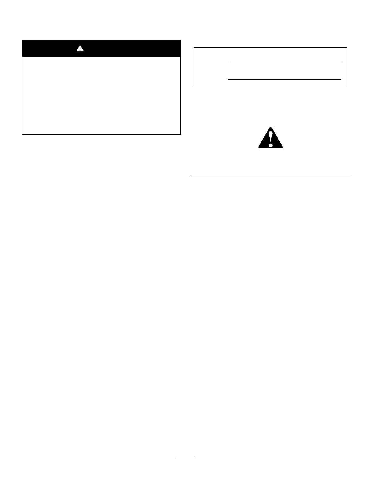
120–2769
93-9356
1.Entanglementhazard—stayawayfrommovingparts.
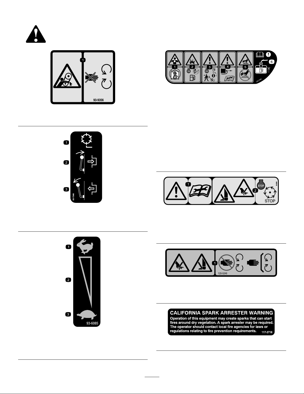
93-7346
1.Reeldrive3.Disengage
2.Engage
1.Toxicgasinhalation
hazard—donotoperate
indoors.
2.Explosionhazard—stop
theengineandkeepaway
fromopenameswhen
refueling.
3.Warning—stoptheengine
andturnoffthefuelbefore
leavingthemachine.
4.Warning—disconnectthe
sparkplugwireandread
theinstructionbefore
servicingorperforming
maintenance.
5.Hotsurface/burn
hazard—donottouch
hotsurfaces.
6.Warning—readthe
Operator’sManual;when
addingfueltothetank,
onlylltothebottomof
thelltube.
93-8064
1.Warning—readtheinstructionsbeforeservicingor
performingmaintenance.
2.Cuttinghazardoffootorhand—stoptheengineandwait
formovingpartstostop.
1.Fast
2.Continuousvariable
setting
125–5245
1.Cuttinghazardofhandorfoot—keepawayfrommoving
parts;keepallguardsandshieldsinplace.
93-6085
3.Slow
117–2718
7
Page 8
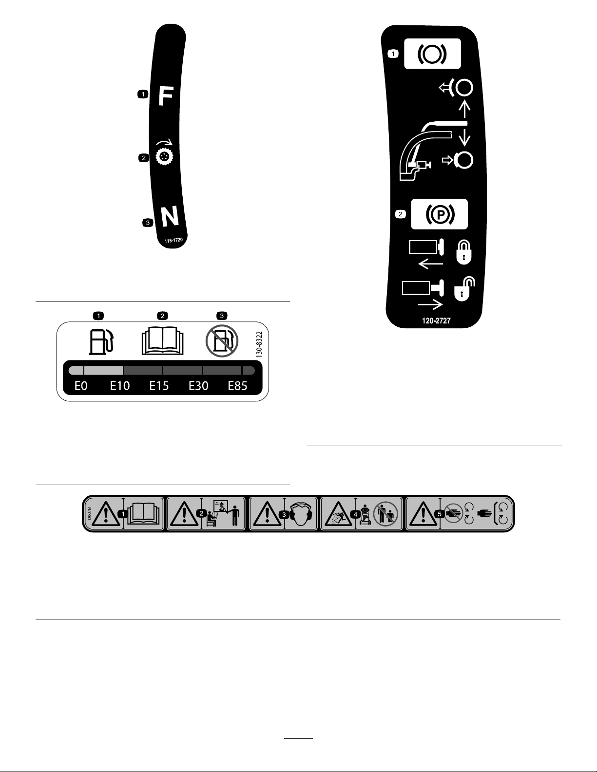
115-1720
1.Forward3.Neutral
2.Drivewheel
120-2727
1.Onlyusegasolinethat
contains10%ethanolby
volume(E10)orless.
2.ReadtheOperator's
Manual.
1.Brake—toengage,pullthe
levertowardthehandle;
todisengage,releasethe
lever.
130-8322
3.Donotusegasolinethat
containsmorethan10%
ethanolbyvolume(E10).
2.Parkingbrake—tolock,
pullthelevertowardthe
handle,pressthebutton
inandreleasethelever
againstthelockingbutton;
torelease,pullthelever
towardthehandleuntil
thebuttonreleasesand
releasethelever .
120–2761
1.Warning—readtheOperator’sManual.4.Thrownobjecthazard—keepbystandersawayfromthe
2.Warning—donotoperatethemachineunlesstheyaretrained.
3.Warning—wearhearingprotection.
machine.
5.Warning—keepawayfrommovingparts;keepallguardsin
place.
8
Page 9
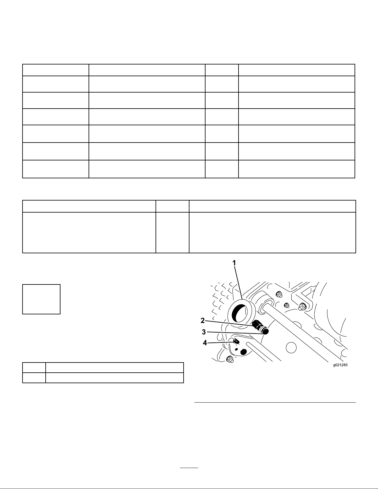
Setup
1
2
3
4
g021285
LooseParts
Usethechartbelowtoverifythatallpartshavebeenshipped.
ProcedureDescription
1
2
3
4
5
6
MediaandAdditionalParts
Description
Operator'sManual
EngineOperator'sManual
PartsCatalog
OperatorTrainingMaterial
CerticateofCompliance
Handle1
Cabletie
Kickstandassembly1
Spring
Wheelshaft,right
Wheelshaft,left
Transportwheels(optional)
Nopartsrequired
Grassbasket
Qty.
1
1
1
1
1
Readorviewbeforeoperatingthemachine.
Qty.
2
1
1
1
2
–
1Installthegrassbasket.
Installthehandle.
Installthekickstand.
Installthetransportwheelshafts.
Installthetransportwheels(optional).
Adjustthecuttingunit.
Use
Use
Note:Determinetheleftandrightsidesofthemachine
fromthenormaloperatingposition.
1
InstallingandAdjustingthe Handle
Partsneededforthisprocedure:
1Handle
2
Cabletie
1.Handlearms3.Bolt,locknutandwasher
2.Mountingpins4.Hairpincotterandringpin
InstallingtheHandle
1.Removethebolts,locknuts,andwasherssecuringthe
bottomofthehandlearmstoeachsideofthemower
(Figure2).
2.Removethehairpincottersandringpinssecuringthe
handlearmstotherearoftheframe(Figure2).
3.Insertthehandleendsthroughtheholesinthehandle
armsandaligntheholeswiththemountingpins
(Figure2).
Figure2
9
Page 10

4.Squeezethehandleendsinwardandinstallthemonthe
g021288
1
2
3
4
G017590
1
G017948
1
2
3
4
mountingpins(Figure3).
Figure3
AdjustingtheHandle
1.Removethehairpincottersfromtheringpinsoneach
sideofthemower(Figure2).
2.Whilesupportingthehandle,removetheringpins
fromeachsideandraiseorlowerthehandletothe
desiredoperatingposition(Figure2).
3.Installtheringpinsandhairpincotters.
2
InstallingtheKickstand(Model GR1610)
1.Handleend
2.Bolt,washer,andlockwasher
3.Hairpincotterandringpin
4.Handlearm
5.Securethehandleendstothemountingpinswiththe
bolts,washers,andlockwasherspreviouslyremoved
(Figure3).
6.Securethehandlearmstotherearoftheframewith
thehairpincottersandringpinspreviouslyremoved
(Figure3).
7.Securethecablesandwireharnesstothehandlewith
cableties(Figure4).
Partsneededforthisprocedure:
1Kickstandassembly
1
Spring
Procedure
Note:Thefastenersareshippedlooselyinstalledonthe
kickstandassembly .
1.Connectthespringstudtotherighthandsideof
thekickstand(Figure5)usingthebolt,washer,and
ange-headnutprovided.
1.Cableties
Figure4
1.Bolt3.Washer
2.Springstud
2.Hookthespringintotheholeinthespringbracketand
ontothespringstudwhilealigningthekickstandwith
themountingholesintherearframe(Figure6).
10
Figure5
4.Flange-headnut
Page 11
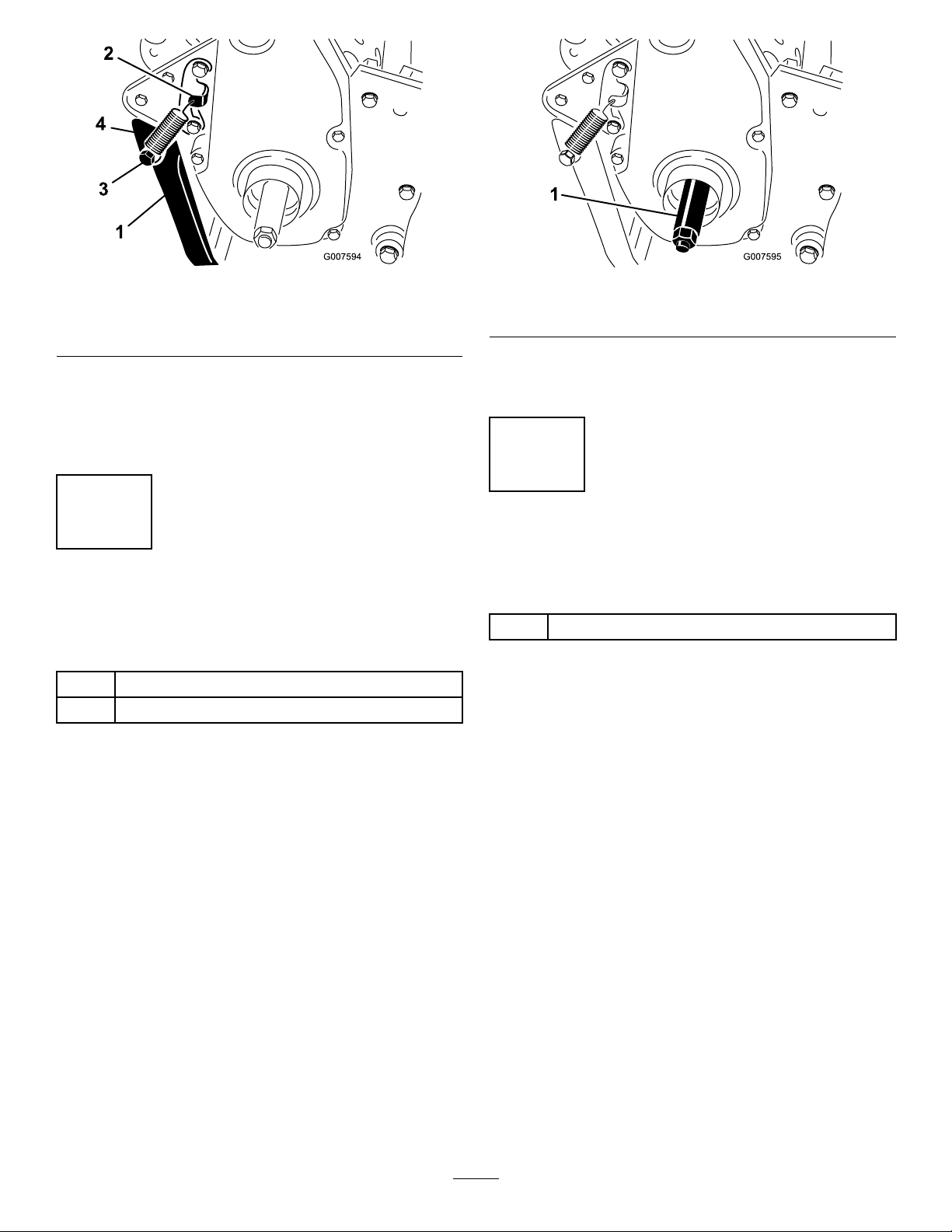
Figure6
Figure7
1.Kickstand
2.Springbracket4.Spring
3.Mountthekickstandtoeachsideoftheframewith
abolt,lockwasher,spacer,atwasherandlocknut
(Figure6).
4.Positionthespacerinthekickstandmountinghole.
3.Springstud
3
InstallingtheTransportWheel Shafts
Partsneededforthisprocedure:
1
Wheelshaft,right
1
Wheelshaft,left
Procedure
1.Pushthekickstanddownwithyourfootandpullup
onthehandletosupportthemoweronthekickstand.
1.Rightwheelshaft
4.Torquetheshaftto688to101N-m(5to75ft-lb).
5.Repeatontheleftside.
4
InstallingtheTransport Wheels(Optional)
Partsneededforthisprocedure:
2
Transportwheels(optional)
Procedure
1.Slidethewheelontotheaxle(Figure8).
2.Pivotthewheellockingclipawayfromcenterofthe
wheelallowingittoslidefartherontotheaxle(Figure
8).
2.Applythread-lockingadhesivetothethreadsofthe
wheelshafts.
3.Threadtherightwheelshaftintothedrivepulleyon
therightsideofthemachine(Figure7).
Note:Therightwheelshafthaslefthandthreads.
11
Page 12
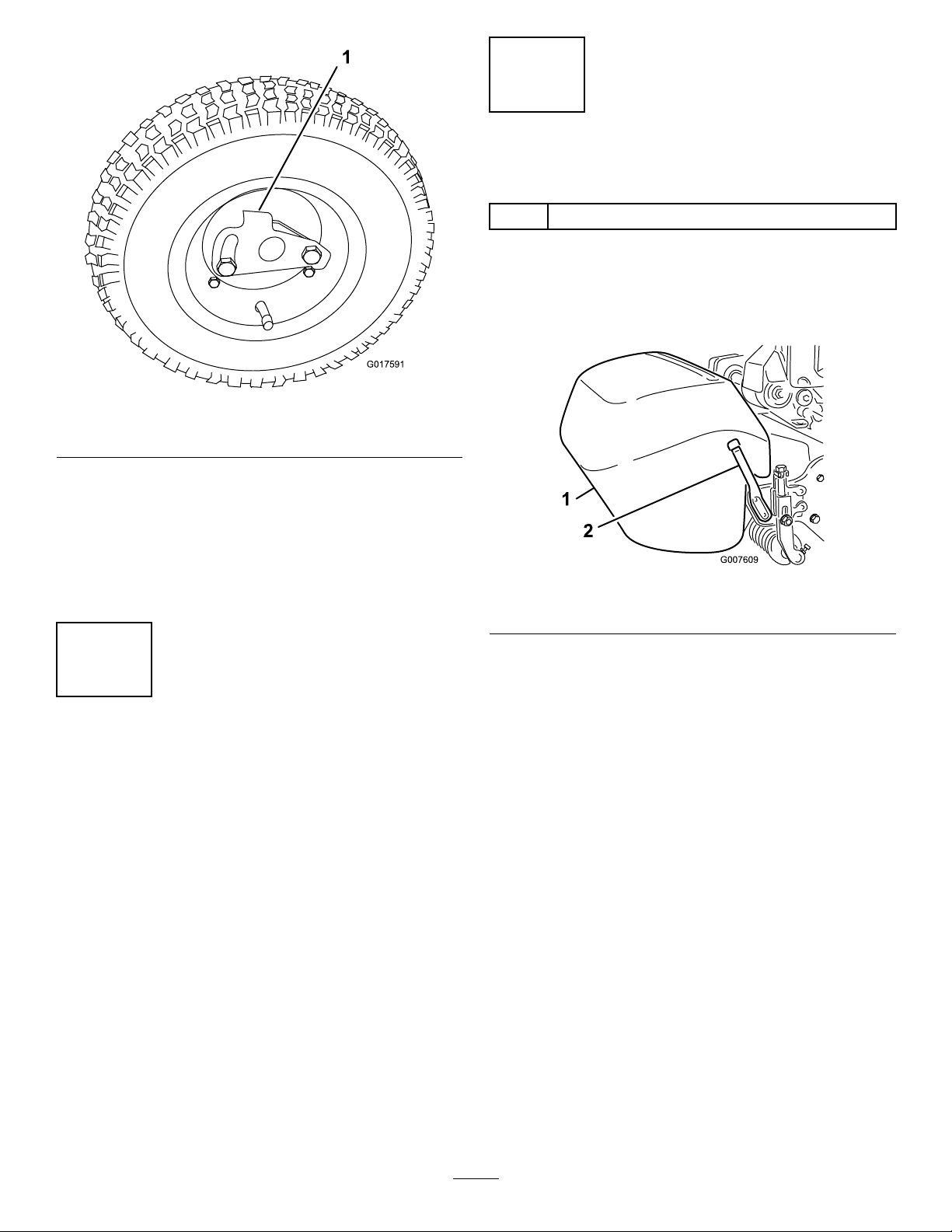
G017591
Figure8
1.Lockingclip
3.Rotatethewheelbackandforthuntilitslides
completelyontotheaxleandthelockingclipissecured
inthegrooveontheaxleshaft.
4.Repeattheprocedureontheoppositesideofthe
machine.
5.Inatethetiresto574to718Pa(12to15psi.).
6
InstallingtheGrassBasket
Partsneededforthisprocedure:
1
Grassbasket
Procedure
Graspthebasketbythetoplipandslideitontothebasket
mountingrods(Figure9).
Figure9
1.Grassbasket
2.Basketmountingrod
5
AdjustingtheCuttingUnit
NoPartsRequired
Procedure
Beforeoperatingthemachine,completethefollowing
adjustments:
•AdjustingtheBedknifetotheReel(page32).
•AdjustingtheHeight-of-Cut(page33).
•AdjustingtheGrassShieldHeight(page34).
•AdjustingtheCut-offBar(page34).
Note:Model04039only—Whencuttinginhigher
heights-of-cut,thebasketmaybeloweredbyremovingeach
basketmountingrodandinstallingeachontheoppositeside
ofthemachine.
12
Page 13

ProductOverview
1
2
3
4
5
6
7
G017592
G016976
G016977
Controls
Figure11
ParkingBrake
Figure10
1.Tractiondrivelever
2.Throttlecontrol6.Parkingbrake
3.On/offswitch7.Operatorpresencecontrol
4.Hourmeter
5.Servicebrake
(optional)
ThrottleControl
Thethrottlecontrol(Figure10)islocatedontherearright
sideofthecontrolpanel.Theleverconnectstoandoperates
thethrottlelinkagetothecarburetor.SeeSpecications(page
14)forenginespeed.
TractionDriveLever
Thetractiondrivelever(Figure10)islocatedonthefront
rightsideofthecontrolpanel.Ithas2positions:Neutral
andForward.Pushingtheleverforwardengagesthetraction
drive.
Theparkingbrake(Figure12)islocatedatthebaseofthe
servicebrake.Fullyengagetheservicebrakeandpushthe
parkingbrakeknobtoallowtheservicebraketorestonthe
parkingbrakepin.Engagetheservicebraketoreleasethe
parkingbrake.Youmustreleasethebrakebeforethetraction
driveisengaged.
Figure12
ServiceBrake
Theservicebrake(Figure11)islocatedonthetopleftfront
sideofthecontrolpanel.Youcanusethebraketoslowor
stopthemachine.
On/OffSwitch
Theon/offswitch(Figure10)islocatedonthetopofthe
controlpanel.MovetheswitchtotheOnpositiontostartthe
engineandtheOffpositiontostoptheengine.
OperatorPresenceControl(Optional)
Ifequipped,theoperatorpresencecontrol(Figure10)is
locatedontherearofthehandle.Pushtheoperatorpresence
controlagainstthehandle.Ifequipped,theoperatorpresence
controlmustbeengagedbeforemovingthetractiondrive
leverortheenginewillstop.
13
Page 14

ReelDriveLever
G016978
1
1
G019637
2
RecoilStarter
Thereeldrivelever(Figure13)islocatedontherightfront
cornerofthemachine.Theleverhas2positions:Engage
andDisengage.Movetheleverforwardtoengagethereelor
rearwardtodisengagethereel.
Figure13
1.Reeldrivelever
ChokeLever
Pulltherecoilstarterhandle(Figure15)tostarttheengine.
Figure15
1.Recoilstarter2.Kickstand
Kickstand
Thekickstand(Figure15)ismountedtotherearofthe
machineandisusedtoraisetherearofthemachinefor
installationorremovalofthetransportwheels.
Thechokelever(Figure14)islocatedontheleftfrontofthe
engine.Theleverhas2positions:RunandChoke.Movethe
levertotheChokepositionwhenstartingacoldengine.After
theenginestarts,movethelevertotheRunposition.
Figure14
1.Chokelever2.Fuelshut-offvalve
Specications
Model04038Model04039
Width
Height
Lengthwithbasket
Dryweight(with
basketandWiehle
roller;without
wheelsorgrooming
reel)
Widthofcut53cm(21inches)66cm(26inches)
Heightofcut
Clip3.6mm(0.14inch)3.6mm(0.14inch)
EnginespeedLowidle–1565
91cm(36inches)104cm(41inches)
99cm(39inches)99cm(39inches)
140cm(55inches)142cm(56inches)
100kg(220lb)105kg(232lb)
1.6mmto31.8
mm(0.063to1.25
inches)
±150rpm,Highidle
–3375±100rpm
3.1mmto31.7
mm(0.125to1.25
inches)
Lowidle–1565
±150rpm,Highidle
–3375±100rpm
FuelShut-offValve
Thefuelshut-offvalve(Figure14)islocatedontheleftfront
oftheenginenearthechokelever.Thevalvehas2positions:
ClosedandOpen.Movetheleveruptotheclosedposition
whenstoringortransportingthemachine.Openthevalve
beforestartingtheenginebyrotatingtheleverdown.
14
Page 15

Attachments/Accessories
AselectionofToroapprovedattachmentsandaccessoriesis
availableforusewiththemachinetoenhanceandexpand
itscapabilities.ContactyourAuthorizedServiceDealeror
Distributororgotowww .Toro.comforalistofallapproved
attachmentsandaccessories.
Operation
Note:Determinetheleftandrightsidesofthemachine
fromthenormaloperatingposition.
ThinkSafetyFirst
Pleasecarefullyreadallofthesafetyinstructionsanddecals
inthesafetysection.Knowingthisinformationcouldhelp
youorbystandersavoidinjury.
CheckingtheEngineOilLevel
Checktheengineoillevelbeforeeachuseorevery8operating
hours,refertoCheckingtheEngineOilLevel(page23)in
EngineMaintenance(page23).
FillingtheFuelTank
Note:Thefueltankcapacityis3.0liters(0.69gallons).
•Forbestresults,useonlyclean,fresh(lessthan30days
old),unleadedgasolinewithanoctaneratingof87or
higher((R+M)/2ratingmethod).
•Ethanol:Gasolinewithupto10%ethanol(gasohol)
or15%MTBE(methyltertiarybutylether)byvolume
isacceptable.EthanolandMTBEarenotthesame.
Gasolinewith15%ethanol(E15)byvolumeisnot
approvedforuse.Neverusegasolinethatcontains
morethan10%ethanolbyvolume,suchasE15
(contains15%ethanol),E20(contains20%ethanol),or
E85(containsupto85%ethanol).Usingunapproved
gasolinemaycauseperformanceproblemsand/orengine
damagewhichmaynotbecoveredunderwarranty.
•Donotusegasolinecontainingmethanol.
•Donotstorefueleitherinthefueltankorfuelcontainers
overthewinterunlessafuelstabilizerisused.
•Donotaddoiltogasoline.
15
Page 16

DANGER
G017594
1
WARNING
Incertainconditions,gasolineisextremely
ammableandhighlyexplosive.Areorexplosion
fromgasolinecanburnyouandothersandcan
damageproperty.
•Fillthefueltankoutdoors,inanopenarea,
whentheengineiscold.Wipeupanygasoline
thatspills.
•Neverllthefueltankinsideanenclosedtrailer.
•Donotllthefueltankcompletelyfull.Add
gasolinetothefueltankuntilthelevelis6to13
mm(1/4to1/2inch)belowthebottomofthe
llerneck.Thisemptyspaceinthetankallows
gasolinetoexpand.
•Neversmokewhenhandlinggasoline,andstay
awayfromanopenameorwheregasoline
fumesmaybeignitedbyaspark.
•Storegasolineinanapprovedcontainerand
keepitoutofthereachofchildren.Neverbuy
morethana30-daysupplyofgasoline.
•Donotoperatewithoutentireexhaustsystemin
placeandinproperworkingcondition.
Gasolineisharmfulorfatalifswallowed.Long-term
exposuretovaporscancauseseriousinjuryand
illness.
•Avoidprolongedbreathingofvapors.
•Keepfaceawayfromnozzleandgastankor
conditionerbottleopening.
•Avoidcontactwithskin;washoffspillagewith
soapandwater.
1.Cleanaroundthefueltankcapandremovethecap
fromthetank(Figure16).
Figure16
DANGER
Incertainconditionsduringfueling,static
electricitycanbereleasedcausingasparkwhich
canignitethegasolinevapors.Areorexplosion
fromgasolinecanburnyouandothersandcan
damageproperty.
•Alwaysplacegasolinecontainersontheground
awayfromyourvehiclebeforelling.
•Donotllgasolinecontainersinsideavehicleor
onatruckortrailerbedbecauseinteriorcarpets
orplastictruckbedlinersmayinsulatethe
containerandslowthelossofanystaticcharge.
•Whenpractical,removegas-poweredequipment
fromthetruckortrailerandrefueltheequipment
withitswheelsontheground.
•Ifthisisnotpossible,thenrefuelsuch
equipmentonatruckortrailerfromaportable
container,ratherthanfromagasolinedispenser
nozzle.
•Ifagasolinedispensernozzlemustbeused,
keepthenozzleincontactwiththerimofthe
fueltankorcontaineropeningatalltimesuntil
fuelingiscomplete.
1.Fueltankcap
2.Usingunleadedgasoline,llthefueltanknohigher
thanthebottomofthelterscreen.Thisspaceallows
thegasolinetoexpand.Donotllthefueltank
completelyfull.
3.Installfueltankcapandwipeupanyspilledgasoline.
16
Page 17

BreakingintheMachine
StartingandStoppingthe
RefertotheEngineManualsuppliedwiththemachineforoil
changeandmaintenanceproceduresrecommendedduring
thebreak-inperiod.
Only8hoursofmowingoperationisrequiredforthebreak-in
period.
Sincethersthoursofoperationarecriticaltofuture
dependabilityofthemachine,monitoritsfunctionsand
performancecloselysothatminordifculties,whichcould
leadtomajorproblems,arenotedandcanbecorrected.
Inspectthemachinefrequentlyduringbreak-inforsignsof
oilleakage,loosefasteners,oranyothermalfunction.
Toensureoptimumperformanceofthebrakesystem,burnish
(break-in)thebrakesbeforeusingthemachine.Toburnish
thebrakes,rmlyapplythebrakesanddrivethemachineat
mowingspeeduntilthebrakesarehot,asindicatedbytheir
smell.Anadjustmenttothebrakesmayberequiredafter
break-in;refertoAdjustingtheService/ParkingBrake(page
26).
CheckingtheInterlockSwitch Operation
Engine
Note:Forillustrationsanddescriptionsofthecontrols
referencedinthissection,refertotheProductOverview
(page13)section.
StartingtheEngine
Note:Ensurethatthesparkplugwireisinstalledonthe
sparkplug.
1.Ensurethatthetractionandreeldriveleversareinthe
Disengagedposition.
Note:Theenginewillnotstartifthetractionleveris
intheEngagedposition.
2.Openthefuelshut-offvalveontheengine.
3.Movetheon/offswitchtotheOnposition.
4.MovethethrottlecontroltotheFastposition.
5.MovethechokeleverhalfwaybetweentheOnandOff
positionswhenstartingacoldengine.Thechokemay
notberequiredwhenstartingawarmengine.
6.Pulltherecoilstarterhandleoutuntilpositive
engagementresults,thenpullitvigorouslytostartthe
engine.
CAUTION
Ifsafetyinterlockswitchesaredisconnectedor
damagedthemachinecouldoperateunexpectedly
causingpersonalinjury.
•Donottamperwiththeinterlockswitches.
•Checktheoperationoftheinterlockswitches
dailyandreplaceanydamagedswitchesbefore
operatingthemachine.
1.Pushthekickstanddownwithyourfootandpullup
andbackonthehandletoraisethewheelsoffofthe
ground.
2.PlacethetractionleverintotheEngagepositionand
theenginecontrolsinthestartingposition.
3.Attempttostarttheengine.
Theengineshouldnotstart.Iftheenginestarts,the
interlockswitchneedsservice.Correcttheproblem
beforeoperating.RefertoServicingtheInterlock
Switch(page26).
4.Carefullyliftuponthehandletoreleasethekickstand.
Important:Donotpullrecoilropetoitslimitor
letgoofstarterhandlewhenropeispulledout
becauseropemaybreakorrecoilassemblymay
bedamaged.
7.MovethechoketotheOffpositionastheengine
warmsup.
StoppingtheEngine
1.Movethetractionandreeldrivecontrolstothe
Disengagedposition,thethrottlecontroltotheSlow
position,andtheOn/OffswitchtotheOffposition.
2.Pullthesparkplugwireoffofthesparkplugtoprevent
thepossibilityofaccidentalstartingbeforestoringthe
machine.
3.Closethefuelshut-offvalvebeforestoringor
transportingthemowerinavehicle.
UsingtheTransportWheels
1.Ifthemachineisequippedwiththeoptionaltransport
wheels,pushthekickstanddownwithyourfootand
pulluponthehandletoraisetherearofthemower
andinstallthetransportwheels.
2.Toreleasethekickstand,pulluponthehandle,push
themowerforward,andthenlowertherearofthe
mowerontothetransportwheels.
3.Ensurethatthetractionandreeldrivecontrolsarein
theDisengagedpositionandstarttheengine.
17
Page 18

4.SetthethrottlecontroltoSlow ,raisethefrontofthe
machineupslightly ,graduallyengagethetractiondrive
andslowlyincreasetheenginespeed.
5.Adjustthethrottletooperatethemoweratthedesired
groundspeedandtransportthemowertothedesired
destination.
6.ReturnthetractioncontrollevertotheDisengage
position,thethrottletotheSlowposition,andstop
theengine.
positionthetrailerortrucksothatitisonthedownside
oftheslopeandtherampextendsuptheslope.Thiswill
minimizetherampangle.Thetrailerortruckshouldbeas
levelaspossible.
Important:Donotattempttoturnthemachinewhile
ontheramp;youmaylosecontrolanddriveofftheside.
Avoidsuddenaccelerationwhendrivinguparampand
suddendecelerationwhenbackingdownaramp.Both
maneuverscancausethemachinetotipbackward.
TransportingtheMachine
Useaheavy-dutytrailerortrucktotransportthemachine.
Ensurethatthetrailerortruckhasallnecessarybrakes,
lighting,andmarkingasrequiredbylaw .Pleasecarefullyread
allthesafetyinstructions.Knowingthisinformationcould
helpyou,yourfamily,pets,orbystandersavoidinjury.
WARNING
Drivingonthestreetorroadwaywithoutturn
signals,lights,reectivemarkings,oraslow
movingvehicleemblemisdangerousandcanlead
toaccidentscausingpersonalinjury.
Donotdrivemachineonapublicstreetorroadway.
Totransportthemachine:
1.Ifusingatrailer,connectittothetowingvehicleand
connectthesafetychains.
2.Ifapplicable,connectthetrailerbrakes.
3.Loadthemachineontothetrailerortruck.
4.Stoptheengine,removethekey,setthebrake,and
closethefuelvalve.
5.Usethemetaltiedownloopsonthemachineto
securelyfastenthemachinetothetrailerortruckwith
straps,chains,cable,orropes.
WARNING
Loadingamachineontoatrailerortruckincreases
thepossibilityofbackwardtip-overandcouldcause
seriousinjuryordeath.
•Useextremecautionwhenoperatingamachine
onaramp.
•EnsurethattheROPSisintheuppositionwhile
usingtheseatbeltwhenloadingthemachine.
EnsurethattheROPSwillclearthetopofan
enclosedtrailer.
•Useonlyasingle,full-widthramp;donotuse
individualrampsforeachsideofthemachine.
•Ifindividualrampsmustbeused,useenough
rampstocreateanunbrokenrampsurfacewider
thanthemachine.
•Donotexceeda15-degreeanglebetweenthe
rampandthegroundorbetweentherampand
thetrailerortruck.
•Avoidsuddenaccelerationwhiledrivingthe
machineuparamp,toavoidtippingbackward.
•Avoidsuddendecelerationwhilebacking
themachinedownaramp,toavoidtipping
backward.
LoadingtheMachine
Useextremecautionwhenloadingthemachineontoatrailer
oratruck.Onefull-widthrampthatiswideenoughtoextend
beyondthereartiresisrecommendedinsteadofindividual
rampsforeachsideofthemachine(Figure17).Thelower
rearsectionofthemachineframeextendsbackbetweenthe
rearwheelsandservesasastopfortippingbackward.Having
afull-widthrampprovidesasurfacefortheframemembers
tocontactifthemachinestartstotipbackward.Ifitisnot
possibletouseonefull-widthramp,useenoughindividual
rampstosimulateafull-widthcontinuousramp.
Therampshouldbelongenoughsothattheanglesdonot
exceed15degrees(Figure17).Asteeperanglemaycause
mowercomponentstogetcaughtastheunitmovesfromthe
ramptothetrailerortruck.Steeperanglesmayalsocause
themachinetotipbackward.Ifloadingonornearaslope,
18
Page 19

Figure17
atthedesiredgroundspeed,drivethemowerontothe
green,lowerthefrontofthemower,andcommence
operation.
4.Whennishedmowing,driveoffofthegreen,move
thetractioncontrollevertotheDisengageposition,
stoptheengineandpushthereeldriveleverintothe
Disengageposition.
5.Emptythegrassbasketofclippings,installthegrass
basket,andcommencetransportoperation.
OperatingTips
BeforeMowing
•Ensurethatthemoweriscarefullyadjustedandisset
evenlyonbothsidesofthereel.Impropermower
adjustmentismagniedmanytimesoverinthe
appearanceoftheclippedturf.
1.Trailer3.Notgreaterthan15
degrees
2.Full-widthramp4.Full-widthramp—side
view
PreparingtoMow
1.Ifthemachineisequippedwiththeoptionaltransport
wheels,pushthekickstanddownwithyourfootand
pullupandbackonthehandletoraisethewheelsoff
oftheground.
2.Pushthelockingclipsonthewheelsoutofthegrooves
intheshafts.
3.Slidethewheelsoffoftheshafts.
4.Movetheunitoffofthekickstand.
Mowing
Properuseofthemachineprovidesthesmoothestturf
cuttingavailable.ReferalsotoOperatingTips(page19)for
fundamentalsuggestionstoobtaintheutmostperformance
fromyourmower.
•Removeallforeignobjectsfromtheturfpriortomowing.
•Ensurethateveryone,especiallychildrenandpets,are
clearoftheworkarea.
MowingTechniques
•Mowagreeninastraightbackandforthdirection,across
thegreen.
•Avoidcircularmowingorturningthemoweronagreen
becausescufngmayoccur.Turnthemoweroffofthe
greenbyraisingthecuttingreel(pushingthehandle
down)andturningonthetractiondrum.
•Mowatanormalwalkingpace.Fastspeedsavesvery
littletimeandwillresultinaninferiormowingjob.
Important:Excessiveoperationofthecuttingunitwith
theabsenceofgrassclippings(lubricant)candamage
thecuttingunit.
1.Starttheengine,setthethrottleatareducedspeed,
pushdownonthehandletoraisethecuttingunit,
movethetractionlevertotheEngagedposition,and
transportthemowerontothecollarofthegreen.
2.MovethetractionlevertotheDisengagedpositionand
movethereeldrivelevertotheEngagedposition.
3.MovethetractionlevertotheEngagedposition,
increasethethrottlespeeduntilthemoweristraveling
19
Page 20

Maintenance
Note:Determinetheleftandrightsidesofthemachinefromthenormaloperatingposition.
RecommendedMaintenanceSchedule(s)
MaintenanceService
Interval
Aftertherst20hours
Beforeeachuseordaily
Every25hours
Every50hours
Every100hours
Every500hours
Every1,000hours
Important:Refertoyour
MaintenanceProcedure
•Changetheengineoil.
•Cleanthefuellterandcup.
•Checktheinterlockswitchoperation.
•Checktheengineoillevel.
•Greasethemachine.(Greasethettingsimmediatelyaftereverywashing
regardlessoftheintervallisted.)
•Changetheengineoil.(Morefrequentlyindustyordirtyconditions)
•Cleanandoiltheaircleanerfoamelement.(Moreoftenindirtyordustyconditions)
•Replacethepaperairlterelement.(Moreoftenindirtyordustyconditions)
•Checkthesparkplug.
•Cleanthefuellterandcup.
•Checkintakeandexhaustvalves.Adjustasnecessary.
•Cleanthecarburetor.
•Replacethefuelline.
•Checkthetransmissiondrivebelts.
•Checkthetransmissionbearings.
Engine Operator's Man ual
foradditionalmaintenanceprocedures.
20
Page 21

DailyMaintenanceChecklist
Important:Duplicatethispageforroutineuse.
Maintenance
CheckItem
Checkthe
safetyinterlock
operation.
Checkthe
parkingbrake
operation.
Checkthefuel
level.
Checktheengine
oillevel.
Checktheair
lter.
Cleantheengine
coolingns.
Checkfor
unusualengine
noises.
Checkfor
unusual
operatingnoises.
Checkthe
reel-to-bedknife
adjustment.
Checkthe
height-of-cut
adjustment.
Greaseall
ttings.
Touchup
damagedpaint.
Fortheweekof:
Mon.Tues.Wed.Thurs.Fri.
Sat.Sun.
NotationforAreasofConcern
Inspectionperformedby:
ItemDate
Information
21
Page 22

Lubrication
G016993
G016981
GreasingtheMachine
ServiceInterval:Every25hours
Lubricatethe13greasettingsonthemowerusingaNo.2
multipurposelithiumbasegrease.Ahandoperatedgrease
gunisrecommendedforbestresults.
Thegreasettinglocationsareasfollows:
•2onthefrontroller(Figure18)
•2onthereelbearings(Figure18)
•2onthedrumaxles(Figure19)
•3onthedifferential(Figure19)
•2onthereelcountershaftbearings(Figure20)
•1onthepowershaftbearing.
•2onthebeltidlerpivots(Figure21).
1.Wipeeachgreasettingwithacleanrag.
2.Pumpgreaseintoeachttinguntilitbeginstoget
difculttopumpthegun.
Important:Donotapplytoomuchpressureor
greasesealswillbecomepermanentlydamaged.
3.Wipeoffanyexcessgrease.
Figure20
Figure21
Figure18
Figure19
22
Page 23

EngineMaintenance
G016983
1
ServicingtheEngineOil
ServiceInterval:Aftertherst20hours—Changethe
engineoil.
Beforeeachuseordaily—Checktheengineoillevel.
Every50hours—Changetheengineoil.(More
frequentlyindustyordirtyconditions)
Thecrankcasemustbelledwithapproximately21uid
ouncesofproperviscosityoilbeforestaring.Theengine
usesanyhigh-qualityoilhavingtheAmericanPetroleum
Institute-APl-“serviceclassication"SF,SG,SHorSJ.Oil
viscosity-weight-mustbeselectedaccordingtoambient
temperature.Figure22illustratesthetemperature/viscosity
recommendations.
CheckingtheEngineOilLevel
1.Positionthemowersothattheengineislevelandclean
aroundtheoillevelgauge(Figure23).
Figure23
1.Oillevelgauge
2.Removetheoillevelgaugebyrotatingit
counterclockwise.
2.Drainplug
Figure22
Note:Usingmulti-gradeoils(5W-20,10W -30,and10W -40)
willincreaseoilconsumption.Checktheoillevelmore
frequentlywhenusingthem.
3.Wipetheoillevelgaugecleanandinsertitintotheller
port.Donotscrewitintotheport.
4.Removethegaugeandchecktheleveloftheoil.
5.Ifthelevelislow,addonlyenoughoiltoraisethelevel
untilitisbetweenthehatchmarksonthegauge(Figure
24).Donotoverll.
Figure24
1.Hatchmarks
6.Installtheoillevelgaugeandwipeupanyspilledoil.
23
Page 24

ChangingtheEngineOil
1
G016984
G016985
1
2
3
4
5
1.Startandruntheengineforafewminutestowarm
theengineoil.
2.Placeadrainpanattherearofmachine,underthe
drainplug(Figure23).
3.Removethedrainplug.
4.Pushdownonthehandletotipthemowerandthe
enginebackward,allowingmoreoiltorunintothe
drainpan.
5.Installthedrainplugandrellthecrankcasewiththe
properoil;refertoCheckingtheEngineOilLevel
(page15).
ServicingtheAirCleaner
distributetheoilthoroughly.Anoildampelement
isdesirable.
ServiceInterval:Every50hours—Cleanandoiltheair
cleanerfoamelement.(Moreoftenin
dirtyordustyconditions)
Every100hours—Replacethepaperairlterelement.
(Moreoftenindirtyordustyconditions)
Important:Servicetheaircleanermoreoftenindirty
ordustyconditions
1.Makesurethewireisoffofthesparkplug.
2.Removethewingnutsecuringtheaircleanercoverand
removethecover(Figure25).
Figure25
Figure26
1.Wingnut4.Foamelement
2.Aircleanercover5.Paperelement
3.Plasticwingnut
5.Checktheconditionofthepaperelement.Cleanitby
gentlytappingorreplaceitasrequired.
Important:Donotusecompressedairtoclean
thepaperelement.
6.Installthefoamelement,paperelement,andaircleaner
cover.
Important:Donotoperatetheenginewithoutthe
aircleanerelementbecauseextremeenginewear
anddamagewilllikelyresult.
1.Aircleanercover
3.Cleanthecoverthoroughly.
4.Ifthefoamelementisdirty ,removeitfromthepaper
element(Figure26)andcleanitthoroughly,asfollows:
A.Washthefoamelementinasolutionofliquid
soapandwarmwater.Squeezeittoremovedirt,
butdonottwistitbecausethefoammaytear.
B.Drythefoamelementbywrappingitinaclean
rag.Squeezetheragandfoamelementtodryit,
butdonottwistit.
C.Saturatethefoamelementwithcleanengineoil.
Squeezetheelementtoremoveexcessoilandto
24
Page 25

ReplacingtheSparkPlug
G016986
1
G019300
1 2
4
3
FuelSystem
ServiceInterval:Every100hours
UseanNGKBR6HSsparkplugorequivalent.Thecorrect
airgapis0.6to0.7mm(0.024to0.028inches).
1.Pullthemoldedwireoffofthesparkplug(Figure27).
Figure27
1.Sparkplugwire
2.Cleanaroundthesparkplugandremoveitfromthe
cylinderhead.
Maintenance
CleaningtheFuelFilter
ServiceInterval:Aftertherst20hours
Every100hours
1.Closethefuelshut–offvalveandunscrewthebowl
fromthelterbody(Figure29).
Important:Replaceacracked,fouled,ordirty
sparkplug.Donotsandblast,scrape,orclean
electrodesbecauseenginedamagecouldresult
fromgritenteringthecylinder.
3.Ensurethattheairgapiscorrect(Figure28).
Figure28
1.Sideelectrode
2.Centerelectrode4.0.6to0.7mm(0.024to
4.Installthecorrectlygappedsparkplugandtightenit
to23N-m(17ft-lb).
5.Installthesparkplugwireonthesparkplug.
3.Insulator
0.028inch)gap
Figure29
1.Bowl
2.Cleanthebowlandlterincleangasolineandinstallit.
2.Fuelshut–offvalve
25
Page 26

ElectricalSystem
G016989
1
2
3
4
G016990
Maintenance
BrakeMaintenance
AdjustingtheService/Parking
ServicingtheInterlockSwitch
Usethefollowingprocedureiftheswitchneedsadjustment
orreplacement.
1.Makesurethattheengineisoffandthetractionleveris
disengagedandrestingagainsttheneutralstop(Figure
30).
Brake
Iftheservice/parkingbrakeslipswhenoperated,an
adjustmentisrequired.
1.Engagetheservicebrake,pushinontheparkingbrake
knobandallowtheservicebraketorestontheparking
brakepin(Figure31)
Figure30
1.Tractionlever3.Interlockswitch
2.Neutralstop
2.Loosentheinterlockswitchmountingfasteners(Figure
30).
3.Placea0.8mm(.032inch)thickshimbetweenthe
tractionleverandtheinterlockswitch(Figure30).
4.Tightentheinterlockswitchmountingfastenersand
checkthegapagain.
Note:Thetractionlevermustnotcontacttheswitch.
5.Engagethetractionleverandverifythattheswitch
losescontinuity .
Note:Replacetheswitchifrequired.
4.0.8mm(0.032inch)gap
Figure31
2.Usingaspringscale,pressrearwardontheservice
brakelever(Figure32).Theparkingbrakeshould
releasewhenaforceof13.5to18kg(30to40lb)is
attained.Iftheparkingbrakereleasesbefore13.5to18
kg(30to40lb)offorceisattained,anadjustmentto
thebrakecableisrequired.Proceedtostep3.
26
Page 27

G016991
1
2
Figure34
Figure32
1.Rearpressureonservicebrakelever
3.LoosentheretainersecuringtheV-beltcoverandpivot
thecoveropen(Figure33).
Figure33
1.V–beltcover2.Retainer
1.Service/Parkingbrake
cable
2.Frontjamnut
5.Closethecoverandsecuretheretainer.
4.Toadjustthebrakecabletension,proceedasfollows.
•Todecreasethecabletension,loosenthefront
cablejamnutandtightentherearjamnut(Figure
34).Repeatsteps1and2andreadjustifrequired.
•Toincreasethecabletension,tightenthefront
cablejamnutandloosentherearjamnut(Figure
34).Repeatsteps1and2andreadjustifrequired.
Note:Theadjustmentcanbeperformedonthe
cableatthejamnutbracketsbythecontrolpanel
oratthebracketatthebaseoftheengine.
27
Page 28

BeltMaintenance
AdjustingtheBelts
Ensurethatthebeltsareproperlytensionedtoensureproper
operationofthemachineandunnecessarywear.Checkthe
beltsfrequently.
5.Whilemaintainingaslightgapbetweenthecoverseal
andthesideplate,installeachmountingboltuntilthe
threadsengageintheinsert.Thegapallowsvisual
alignmentoftheboltstothethreadedinserts.
6.Afterallboltsareinstalled,tightenthemuntilthe
stand-offsinsidethecovercontactthesideplate.Do
notovertighten.
AdjustingtheReelDriveBelt
1.Removethebeltcovermountingfastenersandbelt
covertoexposethebelt(Figure35).
Figure35
1.Beltcover
2.Checkthetensionbypressingthebeltatmidspan
ofthepulleys(Figure36)with18–22N(4to5lb)of
force.Thebeltshoulddeect6mm(1/4inch).
AdjustingtheTractionDriveBelt
1.Removethebeltcovermountingfastenersandthebelt
covertoexposethebelt(Figure37).
Figure37
1.Tractiondrivebeltcover
2.Checkthetensionbypressingthebeltatmidspanof
thepulleys(Figure38)with18to22N(4to5lb)of
force.Thebeltshoulddeect6mm(1/4inch).
Figure36
1.Reeldrivebelt2.Idlerpulley
3.Completethefollowingtoadjustthebelttension:
A.Loosentheidlerpulleymountingnutandpivot
theidlerpulleyclockwiseagainstthebacksideof
thebeltuntilyouattainthedesiredbelttension
(Figure36).
Important:Donotovertensionthebelt.
B.Tightenthenuttolocktheadjustment.
4.Installthebeltcoverbyplacingitinposition.
Figure38
1.Tractiondrivebelt2.Idlerpulley
3.Completethefollowingtoadjustthebelttension:
A.Loosentheidlerpulleymountingnutandpivot
theidlerpulleyclockwiseagainstthebacksideof
thebeltuntilthedesiredbelttensionisattained
(Figure38).
Important:Donotovertensionthebelt.
B.Tightenthenuttolocktheadjustment.
4.Installthebeltcoverbyplacingitinposition.
28
Page 29

5.Whilemaintainingaslightgapbetweenthecoverseal
G016991
1
2
andthesideplate,installeachmountingboltuntilthe
threadsengageintheinsert.Thegapallowsvisual
alignmentoftheboltstothethreadedinserts.
6.Afterallboltsareinstalled,tightenthemuntilthe
stand-offsinsidethecovercontactthesideplate.Do
notovertighten.
AdjustingtheDifferentialBelt
1.Removetheboltssecuringthefrontandrearsections
ofthedifferentialcovertothedifferentialhousingand
slidethecoversectionsawaytoexposethebelt.
2.Checkthetensionbypressingthebeltatmidspanof
thepulleys(Figure39)with22to26N(5to6lb)of
force.Thebeltshoulddeect6mm(1/4inch).
AdjustingthePrimaryV-Belts
1.ToadjustthebelttensiononprimaryV -belts,rst
checktheadjustmentofthetractioncontrol.Refer
toAdjustingtheTractionControl(page31).Ifyou
areunabletoattainthe18to22N(4to5lb)force
requiredinadjustingthetractioncontrol,proceedto
thenextstep.
2.LoosentheretainersecuringtheV-beltcoverandpivot
thecoveropen(Figure40).
Figure39
1.Differentialbelt
2.Idlerpulley
3.Completethefollowingtoadjustthebelttension:
A.Loosentheidlerpulleymountingnutandpivot
theidlerpulleyclockwiseagainstthebacksideof
thebeltuntilthedesiredbelttensionisattained
(Figure39).
Important:Donotovertensionthebelt.
B.Tightenthenuttolocktheadjustment.
4.Installthebeltcoverbyplacingitinposition.
5.Whilemaintainingaslightgapbetweenthecoverseal
andthesideplate,installeachmountingboltuntilthe
threadsengageintheinsert.Thegapallowsvisual
alignmentoftheboltstothethreadedinserts.
Figure40
1.V-beltcover2.Retainer
3.Toincreasebelttension,loosentheenginemounting
boltsandmovetheenginebackwardsintheslots.
Important:Donotovertensionthebelt.
4.Tightenthemountingbolts.
Note:Thedistancebetweenthecentersofthedriver
andthedrivenpulleysshouldbeapproximately12.85
cm(5.06inches)afternewV -beltsareinstalled.
5.AftertensioningtheprimaryV -belts,checkthe
alignmentoftheengineoutputshaftpulleyandthe
counter-shaftpulleywithastraightedge.
6.Ifthepulleysaremisaligned,loosenthescrewssecuring
theenginemountingbasetothemowerframeand
slidetheenginefromsidetosideuntilthepulleysare
alignedwithin0.7mm(0.030inch).
6.Afterallboltsareinstalled,tightenthemuntilthe
stand-offsinsidethecovercontactthesideplate.Do
notovertighten.
29
Page 30

Figure41
1.Locknut3.Idlerpulley
2.Beltguide4.Idlerarm
1.Differentialcoversections
2.Frontclutchhousing
Figure42
3.Rightrearbearinghousing
7.Tightenthemountingscrewsandcheckthealignment.
8.Topushorpullthemachineeasierwithoutstarting
theengine,adjustthebeltguide(Figure41,inset)as
follows:
A.Engagetheclutch.
B.Loosenthelocknutsecuringtheidlerpulleyand
beltguidetotheidlerarm.
C.Rotatethebeltguideclockwiseuntilagapof
approximately0.15cm(0.06inch)isobtained
betweentheguidengerandthebacksideofthe
drivebelts.
D.Tightenthelocknutsecuringtheidlerpulleyand
beltguidetotheidlerarm.
9.Closethecoverandsecuretheretainer.
ReplacingtheDifferentialBelt
1.Removetheboltssecuringthetractiondriveandreel
drivebeltcoverstotherightsideplateandremovethe
beltcovers.
2.Loosentheidlerpulleymountingnutoneachidler
pulleyandpivoteachidlerpulleycounterclockwise
awayfromthebacksideofeachbelttoreleasethebelt
tension.
3.Removethebelts.
4.Removetheboltssecuringthefrontandrearsections
ofthedifferentialcovertothedifferentialhousingand
slidethecoversectionsawaytoexposethebelt(Figure
42).
5.Loosentheidlerpulleymountingnutonthedifferential
idlerpulleyandpivottheidlerpulleycounterclockwise
awayfromthebacksideofthebelttoreleasethebelt
tension.
6.Removethe2boltsandlocknutssecuringthefront
clutchhousingtothesideplate(Figure42).
7.Rotatethehousing180°sothebottomofthehousing
pointsupward.
8.Removethe2boltsandlocknutssecuringtherightrear
bearinghousingtothesideplate(Figure42).
9.Rotatethehousing180°sothebottomofthehousing
pointsupward.Removetheoldbelt.
10.Slidethenewbeltovertherotatedhousingcovers,the
differentialcoversections,andontothedifferential
pulleys.
11.Ensurethattheidlerpulleyispositionedagainstthe
backsideofthebelt.
12.Rotatebothhousingsbackintotheuprightposition
andsecurethemtothesideplatewiththeboltsand
nutspreviouslyremoved.
13.Adjustthedifferentialbelttension;refertoReplacing
theDifferentialBelt(page30).
14.Adjustthebelttensiononthetractiondriveandreel
drivebelts;refertoAdjustingtheTractionDriveBelt
(page28),andAdjustingtheReelDriveBelt(page28).
15.Installthedifferential,tractiondrive,andreeldrive
covers.
30
Page 31

ControlsSystem
Maintenance
CuttingUnitMaintenance
LevelingtheRearDrumtothe
AdjustingtheTractionControl
Ifthetractioncontroldoesnotengageoritslipsduring
operation,anadjustmentisrequired.
1.MovethetractioncontroltotheDisengagedposition.
2.LoosentheretainersecuringtheV-beltcoverandpivot
thecoveropen(Figure40).
3.Toincreasethecabletension,loosenthefrontcable
jamnutandtightenthebackcablejamnut(Figure43)
untilaforceof2.75to3.25kg(6to7lb)toengage
thetractioncontrol.
Note:Measuretheforceatthecontrolknob.
Reel
1.Positionthemachineonaat,levelsurface,preferably
aprecisionsteelworkplate.
2.Placea0.6x2.5cm(1/4x1inch)atsteelstrip,
approximately74cm(29inches)long,underthereel
bladesandagainstthefrontedgeofthebedknifeto
preventthebedbarfromrestingontheworksurface.
3.Raisethefrontrollersoonlythereardrumandreelare
onthesurface.
4.Firmlypressdownonthemachineabovethereelso
allreelbladescontactthesteelstrip.
5.Whilepressingdownonthereel,slideafeelergauge
underoneendofthedrum,thenchecktheotherend
ofthedrum.
Ifthereisagapbetweenthedrumandthework
surface,greaterthan0.25mm(0.010inch),oneither
end,adjustthedrum(proceedtostep6).Ifthegap
islessthan0.25mm(0.010inch)noadjustmentis
required.
6.Removetherearbeltcoverfromtherightsideofthe
machine(Figure44).
Figure43
1.Tractioncable3.Backjamnut
2.Frontjamnut
4.Tightenthefrontcablejamnut.
5.Closethecoverandsecuretheretainer.
6.Checkthetractioncontroloperation.
Figure44
1.Tractiondrivebeltcover
7.Rotatethedrivenpulleyuntiltheholesalignwiththe4
rollerbearingangescrews(Figure45).
31
Page 32

Figure45
1.Drivenpulley3.IdlerPulley
2.4holes
8.Loosenthe4rollerbearingscrewsandthescrew
securingtheidlerpulley.
9.Raiseorlowertherightsideoftherollerassemblyuntil
thegapislessthan0.25mm(0.010inch).
10.Tightentherollerbearingscrews.
11.Adjustthebelttensionandtightentheidlerpulley
mountingscrew(Figure45).
AdjustingtheBedknifetothe
5.Insertthe0.05mm(0.002inch)shimbetweenthe
markedbladeandthebedknifeedgeatthepointwhere
themarkedbladecrossesthebedknifeedge.
6.Turntherightbedbaradjustingscrewuntilyoufeel
lightpressure(i.e.drag)ontheshimbyslidingit
side-to-side(Figure46).Removetheshim.
7.Fortheleftsideofthecuttingunit,slowlyrotatethe
reelsothattheclosestbladecrossesthebedknifeedge
betweentherstandsecondscrewheads.
8.Repeatsteps4through6fortheleftsideofthecutting
unitandleftbedbaradjustingscrew.
9.Repeatsteps5and6untillightdragisachievedon
boththerightandleftsidesofthecuttingunitutilizing
thesamecontactpoints.
10.Toobtainlightcontactbetweenthereelandbedknife,
turneachbedbaradjustingscrewclockwise3clicks.
Note:Eachclickturnedonthebedbaradjusting
screwmovesthebedknife0.018mm(0.0007inches).
Clockwiserotationmovesthebedknifeedgecloser
tothereelandcounterclockwiserotationmovethe
bedknifeedgeawayfromthereel.
11.Testthecuttingperformancebyinsertingalongstrip
ofcuttingperformancepaperbetweenthereeland
bedknife,perpendiculartothebedknife(Figure47).
Slowlyrotatethereelforward;itshouldcutpaper.
Reel
Note:Usethisprocedureaftergrinding,backlapping,or
disassembly.Itisnotintendedasadailyadjustment.
1.Positionthemachineonaat,levelworksurface.
2.Tiltthemowerbackonthehandletoexposethe
bedknifeandthereel.
Important:Donottiltthemachinebackfurther
than60degreestopreventfuelleakage.
3.Rotatethereelsothatabladecrossesthebedknifeedge
betweentherstandsecondbedknifescrewheadson
therightsideofthecuttingunit(Figure46).
Figure46
1.Bedbaradjustingscrew
Figure47
Note:Ifexcessivecontact/reeldragisevidentitwill
benecessarytobacklap,facethefrontofthebedknife,
orgrindthecuttingunittoachievethesharpedges
neededforprecisioncutting.
4.Rotatethereelsothatabladecrossesthebedknifeedge
betweentherstandsecondbedknifescrewheadson
therightsideofthecuttingunit.
32
Page 33

AdjustingtheHeight-of-Cut
1.Verifythattherearrollerislevelandthatthebedknife
toreelcontactiscorrect.Tipthemowerbackonthe
handletoexposethefrontandrearrollersandthe
bedknife.
2.Loosenthelocknutssecuringtheheight-of-cutarmsto
theheight-of-cutbrackets(Figure48).
Figure50
5.Rotatetheadjustingscrewuntiltherollercontactsthe
frontofthegaugebar.
6.Adjustbothendsoftherolleruntiltheentirerolleris
paralleltothebedknife.
Figure48
1.Height-of-cutarm
2.Height-of-cutbracket
3.Locknut
4.Adjustingscrew
3.Loosenthenutonthegaugebar(Figure49)andset
theadjustingscrewtothedesiredheight-of-cut.The
distancebetweenthebottomofthescrewheadandthe
faceofthebaristheheight-of-cut.
Figure49
1.Gaugebar
2.Heightadjustingscrew
3.Nut
Important:Whensetproperly,therearandfront
rollerswillcontactthegaugebarandthescrew
willbesnugagainstthebedknife.Thisensures
theheight-of-cutisidenticalatbothendsofthe
bedknife.
7.Tightennutstolocktheadjustment.
Important:Toavoidscalpingonundulatingturf,
ensurethattherollersupportsarepositioned
rearward(therollerclosertothereel).
Note:Thefrontrollercanbeputinthreedifferent
positions(Figure51),dependingontheapplicationand
needsoftheuser.
•Usethefrontpositionwhenagroomerisinstalled.
•Usethemiddlepositionwithoutagroomer.
•Usethethirdpositioninextremelyundulatingturf
conditions.
4.Hookthescrewheadonthecuttingedgeofthe
bedknifeandresttherearendofthebarontherear
roller(Figure50).
Figure51
33
Page 34

AdjustingtheGrassShield Height
Adjusttheshieldtoensurepropergrassclippingdischarge
intothebasket.
1.Measurethedistancefromthetopofthefrontsupport
rodtothefrontlipoftheshieldateachendofthe
cuttingunit(Figure52).
Figure52
1.Supportrod2.Shield
whentheturfisextremelywet.Bycontrast,adjustthe
barfurtherawayfromthereelwhenturfconditionsare
dry.Thebarshouldbeparalleltothereeltoensure
optimumperformance.Adjustthebarwheneverthe
shieldheightisadjustedorwhenthereelissharpened
onareelgrinder.
BedbarIdentication
Todetermineifthebedbarisstandardoraggressive,check
theleftbedbarmountingears.Ifthemountingearsare
roundeditisastandardbedbar.Ifthemountingearshavea
notchinthem,itisanaggressivebedbar(Figure54).
2.Theheightoftheshieldfromthesupportrodfor
normalcuttingconditionsshouldbe10cm(4inches).
Loosentheboltsandnutssecuringeachendofthe
shieldtothesideplateandadjusttheshieldtothe
correctheight.
3.Tightenthefasteners.
Note:Theshieldcanbeloweredfordrierconditions
(clippingsyovertopofthebasket)orraisedtoallow
forheavywetgrassconditions(clippingsbuildupon
therearofthebasket).
AdjustingtheCut-offBar
Adjustthecut-offbartoensurethattheclippingsarecleanly
dischargedfromthereelarea.
1.Loosenthescrewssecuringthetopbar(Figure53)to
thecuttingunit.
1.Standardbedbar
Figure54
2.Aggressivebedbar
Figure53
1.Cut-offbar
2.Inserta0.15cm(0.060inch)feelergaugebetweenthe
topofthereelandthebarandtightenthescrews.
3.Ensurethatthebarandreelareequaldistancesapart
acrosstheentirereel.
Note:Thebarisadjustabletocompensateforchanges
inturfconditions.Adjustthebarclosertothereel
34
Page 35

SettingtheMachinetoMatchTurfConditions
Usethefollowingtabletosetthemachinetomatchturfconditions.
GreensmowerCuttingUnitSet-upMatrix
Bedbars:StandardandOptional
PartNumberDescriptionMowerAggressiveness
112-9281-01
112-9279-03Aggressive
112-9280-01
110-9278-03Aggressive
Bedknives:StandardandOptional
PartNumberDescriptionMower
93-4262Microcut
115-1880EdgeMaxMicrocut
93-4263T ournament
115-1881EdgeMaxT ournament
93-4264
108-4303ExtendedMicrocut
112-9275Microcut
94-5885T ournament
104-2646
93-9015
117-1548EdgeMaxT ournament
StandardGreensmaster
1010
Greensmaster
1010
StandardGreensmaster
1610
Greensmaster
1610
Greensmaster
1010
Greensmaster
1010
Greensmaster
1010
Greensmaster
1010
LowCutGreensmaster
1010
Greenmaster10101.57-3.1mm(0.062-0.125
Greensmaster
1610
Greensmaster
1610
HighCutGreensmaster
1610
LowCutGreensmaster
1610
Greensmaster
1610
Less
More
Less
More
HeightofCutRangeComments
1.57-3.1mm(0.062-0.125
inches)
1.57-3.1mm(0.062-0.125
inches)
3.1-6mm(0.125-0.250
inches)
3.1-6mm(0.125-0.250
inches)
6mm(0.250inches)andup
inches)
3.1mm(<0.125inches)
6mm(0.250inches)andup
6mm(0.250inches)andup
3.1-6mm(0.125-0.250
inches)
Comments
Standard
Standard
Standard
LessAggressive
Tees
Standard
35
Page 36

Rollers:StandardandOptional
g014780
1
2
PartNumberDescriptionMower
99-6241NarrowWiehle
88-6790WideWiehle
104-2642FullRoller
71-1550WiehleRoller
93-9045WiehleRoller
52-3590
93-9039NarrowWiehle
95-0930FullRoller
ClipTableforFixed-HeadWalk-BehindGreensmowers
Model
04038
04039
Groundspeed4.80km/h(2.98mph)
SwagedRollerGreensmaster1010
StandardClipKit65–9000
StandardreelOptionalreelStandardreelOptionalreel
11–blade
3.8mm(0.15
inches)
11–blade
4.1mm(0.16
inches)
14–blade
3.0mm(0.12
inches)
Greensmaster1010
Greensmaster1010
Greensmaster10102.0inchesSteel
Greensmaster10102.0inchesCastIron
Greensmaster1010
Greensmaster1610
Greensmaster16102.5inchesSteel
8–blade
5.1mm(0.20
inches)
8–blade
5.8mm(0.23
inches)
Diameter/MaterialComments
2.0inchesAluminum
2.0inchesAluminumMorePenetration,0.43
2.5inchesAluminum
2.5inchesAluminum
2.5inchesAluminum
11–blade
5.6mm(0.22
inches)
11–blade
5.6mm(0.22
inches)
14–blade
4.3mm(0.17
Standard,0.2Spacing
Spacing
LeastPenetration
MorePenetration,0.43
Spacing
24inchesWideforEdge
Support
Standard
LeastPenetration
inches)
8–blade
7.6mm(0.30
inches)
8–blade
7.6mm(0.30
inches)
ServicingtheBedbar
RemovingtheBedbar
1.Turnthebedbaradjusterscrewcounterclockwiseto
backthebedknifeawayfromthereel(Figure55).
Figure55
1.Bedbaradjustingscrew3.Bedbar
2.Springtensionnut
2.Backoutthespringtensionnutuntilthewasherisno
longertensionedagainstthebedbar(Figure55).
3.Oneachsideofthemachineloosenthejamnut
securingthebedbarbolt(Figure56).
Figure56
1.Jamnut2.Bedbarbolt
4.Removeeachbedbarboltallowingthebedbartobe
pulleddownwardandremovedfromthemachine.Save
the2nylonand2stampedsteelwashersoneachend
ofthebedbar(Figure56).
InstallingtheBedbar
1.Installthebedbar,positioningthemountingears
betweenthewasherandthebedbaradjuster.
2.Securethebedbartoeachsideplatewiththebedbar
bolts(jamnutsonthebolts)and8washers.Positiona
nylonwasheroneachsideofthesideplateboss.Place
asteelwasheroutsideeachofthenylonwashers.
3.Torquetheboltsto27to36N-m(240to320inch-lb).
36
Page 37

4.Tightenthejamnutsuntiltheoutsidethrustwashers
justrotatefreely.
Storage
5.Tightenthespringtensionnutuntilthespringis
collapsed,thenbackitoff1/2turn.
6.Adjustthebedbar;refertoServicingtheBedbar(page
36).
BacklappingtheReel
1.Removetheplugintherightreeldrivecover(Figure
57).
Figure57
1.Coverplug
1.Removegrassclippings,dirt,andgrimefromthe
externalpartsoftheentiremachine,especiallythe
engine.Cleandirtandchafffromtheoutsideofthe
engine'scylinderheadnsandblowerhousing.
Important:Youcanwashthemachinewithmild
detergentandwater.Donotpressurewashthe
machine.Avoidexcessiveuseofwater,especially
neartheshiftleverplateandengine.
2.Forlong-termstorage(morethan90days)add
stabilizer/conditioneradditivetothefuelinthetank.
A.Runtheenginetodistributeconditionedfuel
throughthefuelsystem(5minutes).
B.Eitherstoptheengine,allowittocool,anddrain
thefueltank,oroperatetheengineuntilitstops.
C.Restarttheengineandrunituntilitstops.Repeat,
onChoke,untiltheenginewillnotrestart.
D.Disposeofthefuelproperly.Recycleasperlocal
codes.
Note:Donotstorestabilizer/conditioned
gasolineover90days.
3.Checkandtightenallbolts,nuts,andscrews.Repairor
replaceanypartthatisdamagedordefective.
2.Inserta1/2inchsocketextension,connectedtothe
backlappingmachine,intothesquareholeinthecenter
ofthereelpulley.
3.BacklapaccordingtotheprocedureintheToro
SharpeningReelandRotaryMowersManual,FormNo.
80-300PT.
DANGER
Contactwiththereelorothermovingparts
canresultinpersonalinjury.
•Stayawayfromthereelwhilebacklapping.
•Neveruseashorthandledpaintbrushfor
backlapping.PartNo.29-9100Handle
assemblycompleteorindividualpartsare
availablefromyourlocalAuthorizedT oro
Distributor.
Note:Forabettercuttingedge,runaleacrossthe
frontfaceofthebedknifewhenthelappingoperation
iscompleted.Thiswillremoveanyburrsorrough
edgesthatmayhavebuiltuponthecuttingedge.
4.Paintallscratchedorbaremetalsurfaces.Paintis
availablefromyourAuthorizedServiceDealer.
5.Storethemachineinaclean,drygarageorstoragearea.
Coverthemachinetoprotectitandkeepitclean.
4.Installthepluginthecoverwhenyouarenishedwith
theprocedure.
37
Page 38

Notes:
38
Page 39

InternationalDistributorList
Distributor:
AgrolancKft
BalamaPrimaEngineeringEquip.HongKong85221552163
B-RayCorporation
CascoSalesCompany
CeresS.A.CostaRica
CSSCTurfEquipment(pvt)Ltd.SriLanka
CyrilJohnston&Co.
CyrilJohnston&Co.RepublicofIreland
EquiverMexico525553995444ParklandProductsLtd.NewZealand6433493760
FemcoS.A.Guatemala
ForGarderOU
G.Y .K.CompanyLtd.
GeomechanikiofAthensGreece
GolfinternationalTurizm
GuandongGoldenStarChina
HakoGroundandGardenSweden
HakoGroundandGarden
HayterLimited(U.K.)
HydroturfInt.CoDubai
HydroturfEgyptLLC
IrrimacPortugal351212388260T oroEuropeNVBelgium3214562960
IrrigationProductsInt'lPvtLtd.India0091442449
JeanHeybroekb.v.Netherlands31306394611VictusEmakPoland48618238369
Country:
Hungary3627539640
Korea82325512076
PuertoRico7877888383
NorthernIreland442890813121
Estonia3723846060
Japan81726325861
Turkey902163365993Riversa
Norway4722907760
UnitedKingdom441279723444
UnitedArabEmirates97143479479T-MarktLogisticsLtd.Hungary3626525500
Egypt2025194308ToroAustraliaAustralia61395807355
PhoneNumber:Distributor:
5062391138
94112746100
442890813121
5024423277
30109350054
862087651338
4635100000
4387
Country:
MaquiverS.A.Colombia
MaruyamaMfg.Co.Inc.
Mountelda.s.CzechRepublic
Mountelda.s.Slovakia
MunditolS.A.
NormaGarden
OslingerTurfEquipmentSA
OyHakoGroundandGarden
Ab
Perfetto
PratoverdeSRL.
Prochaska&Cie
RTCohen2004Ltd.
LelyTurfcare
SolvertS.A.S.
SpyprosStavrinidesLimitedCyprus
SurgeSystemsIndiaLimited
ValtechMorocco21253766
Japan81332522285
Argentina54114821
Russia749541 16120
Ecuador59342396970
Finland35898700733
Poland48618208416
Italy390499128
Austria4312785100
Israel97298617979
Spain
Denmark4566109200
France331308177
India911292299901
Phone
Number:
5712364079
420255704
220
420255704
220
9999
128
34952837500
00
35722434131
3636
EuropeanPrivacyNotice
TheInformationToroCollects
ToroWarrantyCompany(T oro)respectsyourprivacy.Inordertoprocessyourwarrantyclaimandcontactyouintheeventofaproductrecall,weaskyou
tosharecertainpersonalinformationwithus,eitherdirectlyorthroughyourlocalT orocompanyordealer.
TheT orowarrantysystemishostedonserverslocatedwithintheUnitedStateswhereprivacylawmaynotprovidethesameprotectionasapplies
inyourcountry.
BYSHARINGYOURPERSONALINFORMATIONWITHUS,YOUARECONSENTINGTOTHEPROCESSINGOFYOURPERSONALINFORMA TION
ASDESCRIBEDINTHISPRIV ACYNOTICE.
TheWayT oroUsesInformation
Toromayuseyourpersonalinformationtoprocesswarrantyclaims,tocontactyouintheeventofaproductrecallandforanyotherpurposewhichwetell
youabout.ToromayshareyourinformationwithT oro'safliates,dealersorotherbusinesspartnersinconnectionwithanyoftheseactivities.Wewillnot
sellyourpersonalinformationtoanyothercompany.Wereservetherighttodisclosepersonalinformationinordertocomplywithapplicablelawsand
withrequestsbytheappropriateauthorities,tooperateoursystemsproperlyorforourownprotectionorthatofotherusers.
RetentionofyourPersonalInformation
Wewillkeepyourpersonalinformationaslongasweneeditforthepurposesforwhichitwasoriginallycollectedorforotherlegitimatepurposes
(suchasregulatorycompliance),orasrequiredbyapplicablelaw .
Toro'sCommitmenttoSecurityofYourPersonalInformation
Wetakereasonableprecautionsinordertoprotectthesecurityofyourpersonalinformation.Wealsotakestepstomaintaintheaccuracyandcurrent
statusofpersonalinformation.
AccessandCorrectionofyourPersonalInformation
Ifyouwouldliketorevieworcorrectyourpersonalinformation,pleasecontactusbyemailatlegal@toro.com.
AustralianConsumerLaw
AustraliancustomerswillnddetailsrelatingtotheAustralianConsumerLaweitherinsidetheboxoratyourlocalT oroDealer.
374-0269RevH
Page 40

ToroGeneralCommercialProductWarranty
ATwo-YearLimitedWarranty
ConditionsandProductsCovered
TheToroCompanyanditsafliate,T oroWarrantyCompany,pursuant
toanagreementbetweenthem,jointlywarrantyourT oroCommercial
product(“Product”)tobefreefromdefectsinmaterialsorworkmanship
fortwoyearsor1500operationalhours*,whicheveroccursrst.This
warrantyisapplicabletoallproductswiththeexceptionofAerators
(refertoseparatewarrantystatementsfortheseproducts).Wherea
warrantableconditionexists,wewillrepairtheProductatnocosttoyou
includingdiagnostics,labor,parts,andtransportation.Thiswarranty
beginsonthedatetheProductisdeliveredtotheoriginalretailpurchaser.
*Productequippedwithanhourmeter.
InstructionsforObtainingWarrantyService
YouareresponsiblefornotifyingtheCommercialProductsDistributoror
AuthorizedCommercialProductsDealerfromwhomyoupurchasedthe
Productassoonasyoubelieveawarrantableconditionexists.Ifyouneed
helplocatingaCommercialProductsDistributororAuthorizedDealer,or
ifyouhavequestionsregardingyourwarrantyrightsorresponsibilities,
youmaycontactusat:
ToroCommercialProductsServiceDepartment
ToroWarrantyCompany
811 1LyndaleAvenueSouth
Bloomington,MN55420-1196
952–888–8801or800–952–2740
E-mail:commercial.warranty@toro.com
OwnerResponsibilities
AstheProductowner,youareresponsibleforrequiredmaintenanceand
adjustmentsstatedinyourOperator'sManual.Failuretoperformrequired
maintenanceandadjustmentscanbegroundsfordisallowingawarranty
claim.
ItemsandConditionsNotCovered
Notallproductfailuresormalfunctionsthatoccurduringthewarranty
periodaredefectsinmaterialsorworkmanship.Thiswarrantydoesnot
coverthefollowing:
•Productfailureswhichresultfromtheuseofnon-T ororeplacement
parts,orfrominstallationanduseofadd-on,ormodiednon-Toro
brandedaccessoriesandproducts.Aseparatewarrantymaybe
providedbythemanufactureroftheseitems.
•Productfailureswhichresultfromfailuretoperformrecommended
maintenanceand/oradjustments.Failuretoproperlymaintainyour
ToroproductpertheRecommendedMaintenancelistedinthe
Operator’sManualcanresultinclaimsforwarrantybeingdenied.
•ProductfailureswhichresultfromoperatingtheProductinanabusive,
negligent,orrecklessmanner.
•Partssubjecttoconsumptionthroughuseunlessfoundtobedefective.
Examplesofpartswhichareconsumed,orusedup,duringnormal
Productoperationinclude,butarenotlimitedto,brakepadsand
linings,clutchlinings,blades,reels,rollersandbearings(sealedor
greasable),bedknives,sparkplugs,castorwheelsandbearings,tires,
lters,belts,andcertainsprayercomponentssuchasdiaphragms,
nozzles,andcheckvalves,etc.
•Failurescausedbyoutsideinuence.Conditionsconsideredtobe
outsideinuenceinclude,butarenotlimitedto,weather,storage
practices,contamination,useofunapprovedfuels,coolants,lubricants,
additives,fertilizers,water,orchemicals,etc.
•Failureorperformanceissuesduetotheuseoffuels(e.g.gasoline,
diesel,orbiodiesel)thatdonotconformtotheirrespectiveindustry
standards.
•Normalnoise,vibration,wearandtear ,anddeterioration.
•Normal“wearandtear”includes,butisnotlimitedto,damagetoseats
duetowearorabrasion,wornpaintedsurfaces,scratcheddecalsor
windows,etc.
Parts
Partsscheduledforreplacementasrequiredmaintenancearewarranted
fortheperiodoftimeuptothescheduledreplacementtimeforthatpart.
Partsreplacedunderthiswarrantyarecoveredforthedurationofthe
originalproductwarrantyandbecomethepropertyofT oro.T orowillmake
thenaldecisionwhethertorepairanyexistingpartorassemblyorreplace
it.T oromayuseremanufacturedpartsforwarrantyrepairs.
DeepCycleandLithium-IonBatteryWarranty:
DeepcycleandLithium-Ionbatterieshaveaspeciedtotalnumberof
kilowatt-hourstheycandeliverduringtheirlifetime.Operating,recharging,
andmaintenancetechniquescanextendorreducetotalbatterylife.Asthe
batteriesinthisproductareconsumed,theamountofusefulworkbetween
chargingintervalswillslowlydecreaseuntilthebatteryiscompletelyworn
out.Replacementofwornoutbatteries,duetonormalconsumption,
istheresponsibilityoftheproductowner.Batteryreplacementmaybe
requiredduringthenormalproductwarrantyperiodatowner’sexpense.
Note:(Lithium-Ionbatteryonly):ALithium-Ionbatteryhasapartonly
proratedwarrantybeginningyear3throughyear5basedonthetime
inserviceandkilowatthoursused.RefertotheOperator'sManualfor
additionalinformation.
MaintenanceisatOwner’sExpense
Enginetune-up,lubrication,cleaningandpolishing,replacementoflters,
coolant,andcompletingrecommendedmaintenancearesomeofthe
normalservicesT oroproductsrequirethatareattheowner’sexpense.
GeneralConditions
RepairbyanAuthorizedToroDistributororDealerisyoursoleremedy
underthiswarranty.
NeitherTheToroCompanynorToroWarrantyCompanyisliablefor
indirect,incidentalorconsequentialdamagesinconnectionwiththe
useoftheToroProductscoveredbythiswarranty,includingany
costorexpenseofprovidingsubstituteequipmentorserviceduring
reasonableperiodsofmalfunctionornon-usependingcompletion
ofrepairsunderthiswarranty.ExceptfortheEmissionswarranty
referencedbelow,ifapplicable,thereisnootherexpresswarranty.All
impliedwarrantiesofmerchantabilityandtnessforusearelimitedto
thedurationofthisexpresswarranty.
Somestatesdonotallowexclusionsofincidentalorconsequential
damages,orlimitationsonhowlonganimpliedwarrantylasts,sotheabove
exclusionsandlimitationsmaynotapplytoyou.Thiswarrantygivesyou
speciclegalrights,andyoumayalsohaveotherrightswhichvaryfrom
statetostate.
Noteregardingenginewarranty:
TheEmissionsControlSystemonyourProductmaybecoveredby
aseparatewarrantymeetingrequirementsestablishedbytheU.S.
EnvironmentalProtectionAgency(EP A)and/ortheCaliforniaAirResources
Board(CARB).Thehourlimitationssetforthabovedonotapplytothe
EmissionsControlSystemWarranty.RefertotheEngineEmissionControl
WarrantyStatementsuppliedwithyourproductorcontainedintheengine
manufacturer’sdocumentationfordetails
CountriesOtherthantheUnitedStatesorCanada
CustomerswhohavepurchasedT oroproductsexportedfromtheUnitedStatesorCanadashouldcontacttheirT oroDistributor(Dealer)toobtain
guaranteepoliciesforyourcountry ,province,orstate.IfforanyreasonyouaredissatisedwithyourDistributor'sserviceorhavedifcultyobtaining
guaranteeinformation,contacttheT oroimporter.
374-0253RevC
 Loading...