

Page 1

FormNo.3367-413RevA
Greensmaster
®
2000and2600
Walk-BehindMower
ModelNo.04036—SerialNo.311000001andUp
ModelNo.04037—SerialNo.311000001andUp
ToregisteryourproductordownloadanOperator'sManualorPartsCatalogatnocharge,gotowww.T oro.com.OriginalInstructions(EN)
Page 2

ThisproductcomplieswithallrelevantEuropean
directives,fordetailspleaseseetheseparateproduct
specicDeclarationofConformity(DOC)sheet.
WARNING
Figure1
1.Safetyalertsymbol.
CALIFORNIA
Proposition65Warning
Theengineexhaustfromthisproduct
containschemicalsknowntotheStateof
Californiatocausecancer,birthdefects,
orotherreproductiveharm.
ThissparkignitionsystemcomplieswithCanadian
ICES-002.
Introduction
Thismachineisawalkbehind,reel-bladelawnmower
intendedtobeusedbyprofessional,hiredoperatorsin
commercialapplications.Itisprimarilydesignedfor
cuttinggrassonwell-maintainedlawnsinparks,golf
courses,sportselds,andoncommercialgrounds.Itis
notdesignedforcuttingbrush,mowinggrassandother
growthalongsidehighways,orforagriculturaluses.
Readthisinformationcarefullytolearnhowtooperate
andmaintainyourproductproperlyandtoavoidinjury
andproductdamage.Youareresponsibleforoperating
theproductproperlyandsafely.
Thismanualusestwootherwordstohighlight
information.Importantcallsattentiontospecial
mechanicalinformationandNoteemphasizesgeneral
informationworthyofspecialattention.
YoumaycontactTorodirectlyatwww .Toro.comfor
productandaccessoryinformation,helpndinga
dealer,ortoregisteryourproduct.
Wheneveryouneedservice,genuineToroparts,or
additionalinformation,contactanAuthorizedService
DealerorToroCustomerServiceandhavethemodel
andserialnumbersofyourproductready .Themodel
andserialnumbersarelocatedonaplateontherear
frame.Writethenumbersinthespaceprovided.
ModelNo.
SerialNo.
Thismanualidentiespotentialhazardsandhas
safetymessagesidentiedbythesafetyalertsymbol
(Figure1),whichsignalsahazardthatmaycauseserious
injuryordeathifyoudonotfollowtherecommended
precautions.
©2010—TheT oro®Company
8111LyndaleAvenueSouth
Bloomington,MN55420
Contactusatwww.Toro.com.
2
PrintedintheUSA.
AllRightsReserved
Page 3

Contents
Introduction.................................................................2
Safety...........................................................................4
SafeOperatingPractices.......................................4
ToroMowerSafety...............................................5
SoundPressure.....................................................6
SoundPower........................................................6
Vibration(Model04036)......................................6
Vibration(Model04037)......................................6
SafetyandInstructionalDecals.............................7
Setup............................................................................9
1InstallingandAdjustingtheHandle....................9
2InstalltheLiftHandles.....................................11
3InstallingtheKickstand(Model04037
Only)..............................................................11
4InstallingtheTransportWheels........................12
5AdjustingtheCuttingUnit...............................13
6InstallingtheGrassBasket...............................13
ProductOverview......................................................14
Controls.............................................................14
Specications.....................................................15
Attachments/Accessories...................................15
Operation...................................................................16
ThinkSafetyFirst...............................................16
CheckingtheEngineOilLevel............................16
FillingtheFuelTank...........................................16
CheckingtheInterlockSwitchOperation............17
StartingandStoppingtheEngine........................17
DrivingtheMachineinTransport.......................17
PreparingtoMow...............................................18
Mowing..............................................................18
OperatingTips...................................................18
Maintenance...............................................................19
RecommendedMaintenanceSchedule(s)................19
DailyMaintenanceChecklist...............................20
Lubrication.............................................................21
GreasingtheMachine.........................................21
EngineMaintenance...............................................22
ServicingtheEngineOil.....................................22
ServicingtheAirCleaner....................................23
ReplacingtheSparkPlug....................................23
FuelSystemMaintenance.......................................24
CleaningtheFuelFilter.......................................24
ElectricalSystemMaintenance................................25
ServicingtheInterlockSwitch............................25
BrakeMaintenance.................................................25
AdjustingtheService/ParkingBrake...................25
BeltMaintenance....................................................27
AdjustingtheBelts.............................................27
ReplacingtheDifferentialBelt............................29
ControlsSystemMaintenance.................................30
AdjustingtheTractionControl...........................30
CuttingUnitMaintenance.......................................30
LevelingtheRearDrumtotheReel.....................30
AdjustingtheBedknifetotheReel......................31
AdjustingtheHeightofCut................................31
AdjustingtheGrassShieldHeight.......................32
AdjustingtheCut-OffBar..................................33
BedbarIdentication..........................................33
SettingtheMachinetoMatchTurf
Conditions.....................................................34
ServicingtheBedbar...........................................35
BacklappingtheReel..........................................35
Storage.......................................................................36
3
Page 4

Safety
ThismachinemeetsorexceedsCENstandard
EN836:1997,ISOstandard5395:1990,andANSI
B71.4-2004specicationsineffectatthetimeof
productionwhentheOperatorPresenceKit,PartNo.
105–5363isinstalled.
Improperuseormaintenancebytheoperatoror
ownercanresultininjury.Toreducethepotential
forinjury,complywiththesesafetyinstructionsand
alwayspayattentiontothesafetyalertsymbol,which
meansCaution,Warning,orDanger—personalsafety
instruction.Failuretocomplywiththeinstructionmay
resultinpersonalinjuryordeath.
•Warning—Fuelishighlyammable.Takethe
followingprecautions:
–Storefuelincontainersspecicallydesignedfor
thispurpose.
–Refueloutdoorsonlyanddonotsmokewhile
refuelling.
–Addfuelbeforestartingtheengine.Never
removethecapofthefueltankoraddfuelwhile
theengineisrunningorwhentheengineishot.
–Iffuelisspilled,donotattempttostartthe
enginebutmovethemachineawayfromthe
areaofspillageandavoidcreatinganysourceof
ignitionuntilfuelvaporshavedissipated.
–Replaceallfueltanksandcontainercapssecurely.
SafeOperatingPractices
ThefollowinginstructionsarefromtheCENstandard
EN836:1997,ISOstandard5395:1990,andANSI
B71.4-2004.
Training
•ReadtheOperator’sManualandothertraining
materialcarefully .Befamiliarwiththecontrols,
safetysigns,andtheproperuseoftheequipment.
•Iftheoperatorormechaniccannotreadthe
languageoftheOperator’sManualitistheowner’s
responsibilitytoexplainthismaterialtothem.
•Neverallowchildrenorpeopleunfamiliarwiththese
instructionstouseorservicethemower.Local
regulationsmayrestricttheageoftheoperator.
•Nevermowwhilepeople,especiallychildren,orpets
arenearby .
•Keepinmindthattheoperatororuserisresponsible
foraccidentsorhazardsoccurringtootherpeopleor
theirproperty.
•Theowner/usercanpreventandisresponsiblefor
accidentsorinjuriesoccurringtohimselforherself,
otherpeople,orproperty.
•Alloperatorsormechanicsmustbetrained.Itisthe
owner’sresponsibilityfortrainingusers.
•Replacefaultysilencers.
•Evaluatetheterraintodeterminewhataccessories
andattachmentsareneededtoproperlyand
safelyperformthejob.Onlyuseaccessoriesand
attachmentsapprovedbythemanufacturer.
•Checkthatoperatorspresencecontrols,safety
switchesandshieldsareattachedandfunctioning
properly.Donotoperateunlesstheyarefunctioning
properly.
Operation
•Donotoperatetheengineinaconnedspacewhere
dangerouscarbonmonoxidefumescancollect.
•Mowonlyindaylightoringoodarticiallight.
•Beforeattemptingtostarttheengine,disengageall
bladeattachmentclutches,shiftintoneutral,and
engagetheparkingbrake.
•Stayalertforholesintheterrainandotherhidden
hazards.
•Watchoutfortrafcwhencrossingornearroadways.
•Stopthebladesrotatingbeforecrossingsurfaces
otherthangrass.
•Whenusinganyattachments,neverdirectdischarge
ofmaterialtowardbystandersnorallowanyonenear
themachinewhileinoperation.
Preparation
•Whilemowing,alwayswearsubstantialfootwear,
longtrousers,hardhat,safetyglasses,andhearing
protection.Longhair,looseclothing,orjewelrymay
gettangledinmovingparts.Donotoperatethe
equipmentwhenbarefootorwearingopensandals.
•Thoroughlyinspecttheareawheretheequipment
istobeusedandremoveallobjectswhichmaybe
thrownbythemachine.
•Neveroperatethemachinewithdamagedguards,
shields,orwithoutsafetyprotectivedevicesinplace.
Besureallinterlocksareattached,adjustedproperly ,
andfunctioningproperly .
•Donotchangetheenginegovernorsettingsor
overspeedtheengine.Operatingtheengineat
excessivespeedmayincreasethehazardofpersonal
injury.
•Beforeleavingtheoperatorsposition:
4
Page 5

–stoponlevelground;
–disengagethecuttingunitandtractiondrive;
–settheparkingbrake;
–stoptheengine.
•Disengagedrivetocuttingunitwhentransportingor
notinuse.
•Stoptheengineanddisengagedrivetocuttingunit:
–beforerefuelling;
–beforeremovingthegrasscatcher;
–beforemakingheightadjustment.
–beforeclearingblockages;
–beforechecking,cleaningorworkingonthe
mower;
–afterstrikingaforeignobjectorifanabnormal
vibrationoccurs.Inspectthemowerfordamage
andmakerepairsbeforerestartingandoperating
theequipment.
•Reducethethrottlesettingbeforestoppingengine
andclosethefuelshutoffvalveattheconclusion
ofmowing.
•Keephandsandfeetawayfromthecuttingunit.
•Slowdownandusecautionwhenmakingturns
andcrossingroadsandsidewalks.Stopreelifnot
mowing.
•Donotoperatethemowerundertheinuenceof
alcoholordrugs
•Lightningcancausesevereinjuryordeath.If
lightningisseenorthunderisheardinthearea,do
notoperatethemachine;seekshelter.
•Usecarewhenloadingorunloadingthemachine
intoatrailerortruck
•Usecarewhenapproachingblindcorners,shrubs,
trees,orotherobjectsthatmayobscurevision.
MaintenanceandStorage
•Keepallnuts,boltsandscrewstighttobesurethe
equipmentisinsafeworkingcondition.
•Neverstoretheequipmentwithfuelinthetank
insideabuildingwherefumesmayreachanopen
ameorspark.
•Allowtheenginetocoolbeforestoringinany
enclosure.
•Toreducetherehazard,keeptheengine,silencer
andfuelstorageareafreeofgrass,leaves,orexcessive
grease.
•Checkthegrasscatcherfrequentlyforwearor
deterioration.
•Keepallpartsingoodworkingconditionandall
hardwareandhydraulicttingstightened.Replaceall
wornordamagedpartsanddecals.
•Ifthefueltankhastobedrained,dothisoutdoors.
•Becarefulduringadjustmentofthemachineto
prevententrapmentofthengersbetweenmoving
bladesandxedpartsofthemachine.
•Disengagedrives,disengagethecuttingunit,set
parkingbrake,stopengineanddisconnectsparkplug
wire.Waitforallmovementtostopbeforeadjusting,
cleaningorrepairing.
•Cleangrassanddebrisfromcuttingunit,drives,
mufers,andenginetohelppreventres.Cleanup
oilorfuelspillage.
•Carefullyreleasepressurefromcomponentswith
storedenergy.
•Removethesparkplugwirebeforemakingany
repairs.
•Usecarewhencheckingthereel.W earglovesand
usecautionwhenservicingthem.
•Keephandsandfeetawayfrommovingparts.If
possible,donotmakeadjustmentswiththeengine
running.
ToroMowerSafety
Thefollowinglistcontainssafetyinformationspecic
toToroproductsorothersafetyinformationthatyou
mustknowthatisnotincludedintheCEN,ISO ,or
ANSIstandard.
Thisproductiscapableofamputatinghandsand
feetandthrowingobjects.Alwaysfollowallsafety
instructionstoavoidseriousinjuryordeath.
Useofthisproductforpurposesotherthanitsintended
usecouldprovedangeroustouserandbystanders.
•Knowhowtostoptheenginequickly.
•Donotoperatethemachinewhilewearingtennis
shoesorsneakers.
•Wearingsafetyshoesandlongpantsisadvisableand
requiredbysomelocalordinancesandinsurance
regulations.
•Handlegasolinecarefully.Wipeupanyspills.
•Checkthesafetyinterlockswitchesdailyforproper
operation.Ifaswitchshouldfail,replacetheswitch
beforeoperatingthemachine.
•Usingthemachinedemandsattention.T oprevent
lossofcontrol:
–Donotoperateclosetosandtraps,ditches,
creeks,orotherhazards.
5
Page 6

–Reducespeedwhenmakingsharpturns.Avoid
suddenstopsandstarts.
–Whennearorcrossingroads,alwaysyieldthe
right-of-way.
–Reduceenginespeedandapplytheservicebrake
whengoingdownhilltokeepforwardspeedslow
andtomaintaincontrolofthemachine.
•Donottouchtheengine,mufer,orexhaustpipe
whiletheengineisrunningorsoonafterithas
stoppedbecausetheseareascouldbehotenough
tocauseburns.
•Whenapersonorpetappearsunexpectedlyinor
nearthemowingarea,stopmowing.Careless
operation,combinedwithterrainangles,ricochets,
orimproperlypositionedguardscanleadtothrown
objectinjuries.Donotresumemowinguntilthe
areaiscleared.
MaintenanceandStorage
•Checkallfuellinesfortightnessandwearona
regularbasis.Tightenorrepairthemasneeded.
•Iftheenginemustberunningtoperforma
maintenanceadjustment,keephands,feet,clothing,
andanypartsofthebodyawayfromthecuttingunit
andanymovingparts.Keepeveryoneaway.
•Toensuresafetyandaccuracy,haveanAuthorized
ToroDistributorcheckthemaximumenginespeed
withatachometer.Maximumgovernedenginespeed
shouldbe3600±100RPM.
•Ifmajorrepairsareeverneededorifassistanceis
desired,contactanAuthorizedToroDistributor.
•UseonlyToroapprovedattachmentsand
replacementparts.Thewarrantymaybevoidedif
usedwithunapprovedattachments.
Vibration(Model04037)
Thisunitdoesnotexceedahand/armvibrationlevelof
4.50m/s
perEN1033andEN836.
2
,basedonmeasurementsofidenticalmachines
SoundPressure
Thisunithasamaximumsoundpressurelevelatthe
operatorsearof84dBA,basedonmeasurementsof
identicalmachinesperEN836andISO11201.
SoundPower
Thisunithasaguaranteedsoundpowerlevelof95
dBA,basedonmeasurementsofidenticalmachinesper
ISO11094.
Vibration(Model04036)
Thisunitdoesnotexceedahand/armvibrationlevelof
4.50m/s
perEN1033andEN836.
2
,basedonmeasurementsofidenticalmachines
6
Page 7
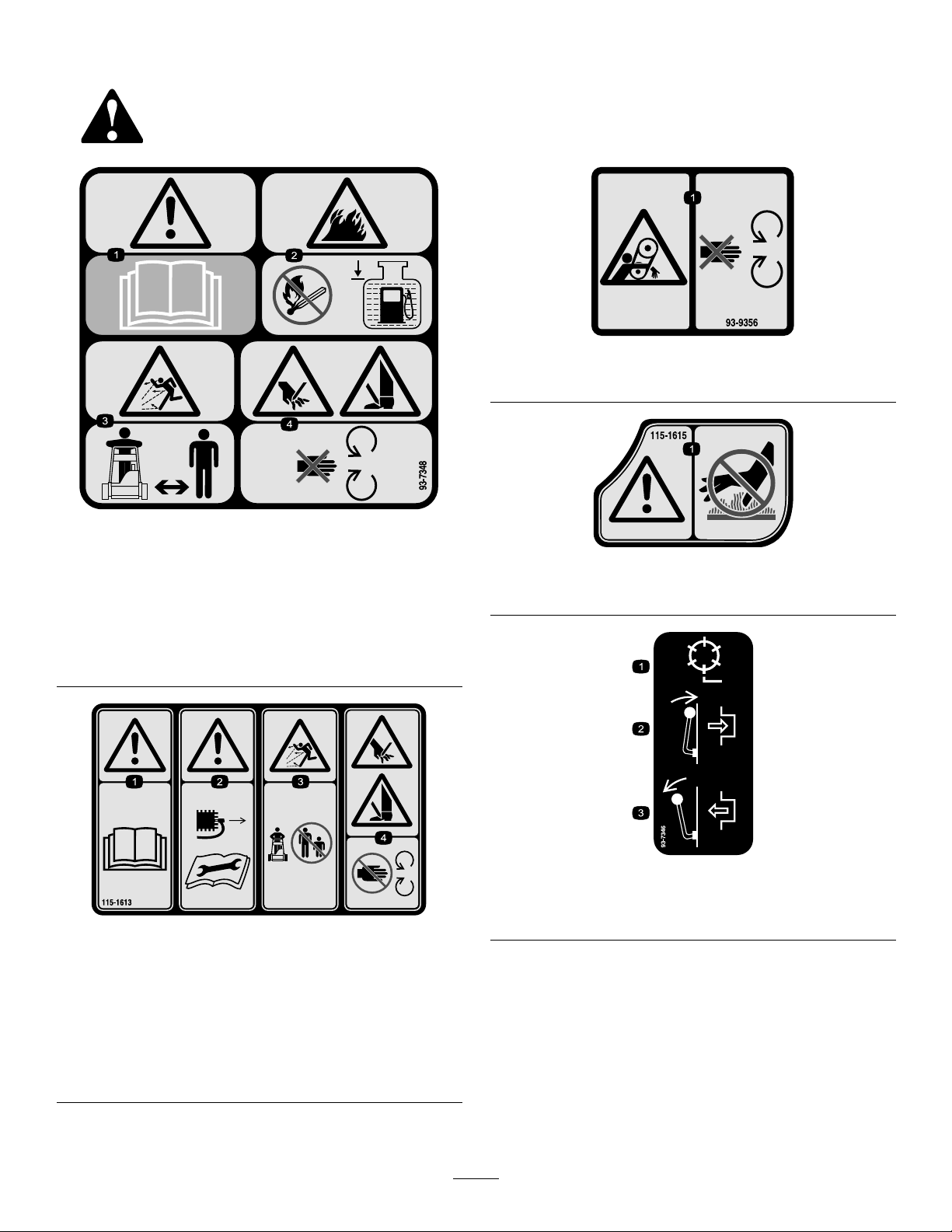
SafetyandInstructionalDecals
Safetydecalsandinstructionsareeasilyvisibletotheoperatorandarelocatednearanyareaof
potentialdanger.Replaceanydecalthatisdamagedorlost.
93-9356
1.Entanglementhazard—stayawayfrommovingparts.
93-7348
1.Warning—readtheOperator’sManual.
2.Firehazard—nore,openames,orsmoking;whenadding
fueltothetank,leavespacebetweenthefuelandthetopof
thetank.
3.Thrownobjecthazard—keepbystandersasafedistance
fromthemachine.
4.Cuttinghazardofhandorfoot—stayawayfrommoving
parts
115-1613
1.Warning—readthe
Operator’sManual.
2.Warning—remove
thesparkplugwire
beforeperformingany
maintenanceonthe
machine.
3.Thrownobject
hazard—keepbystanders
asafedistancefromthe
machine.
4.Cutting,dismemberment
hazardofhandor
foot—stayawayfrom
movingparts.
115-1615
1.Warning—donottouchthehotsurface.
93-7346
1.Reeldrive3.Disengage
2.Engage
7
Page 8
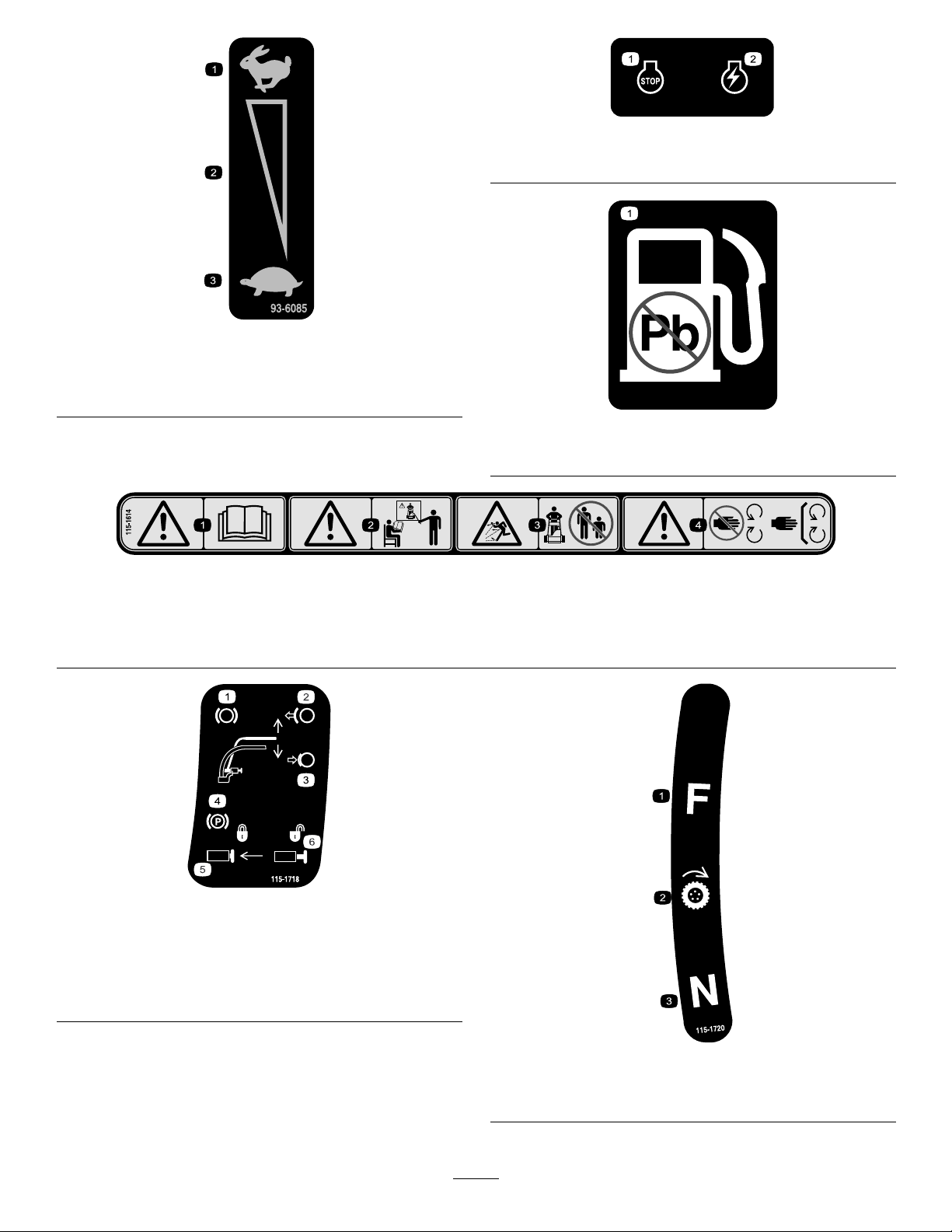
112-9408
1.Engine—stop2.Engine—run
93-6085
1.Fast
2.Continuousvariable
setting
3.Slow
93-9886
1.Useunleadedgasoline.
115-1614
1.Warning—readtheOperator’sManual.3.Thrownobjecthazard—keepbystandersasafedistancefrom
2.Warning—donotoperatethemachineunlessyouaretrained.
themachine.
4.Warning—stayawayfrommovingparts;keepallguardsin
place.
115-1718
1.Brake4.Parkingbrake
2.Releasethehandleto
disengagethebrake
3.Compressthehandleto
engagethebrake
5.Pushintheswitchtolock
theparkingbrake
6.Pullouttheswitchto
unlocktheparkingbrake
115-1720
1.Forward3.Neutral
2.Drivewheel
8
Page 9

Setup
LooseParts
Usethechartbelowtoverifythatallpartshavebeenshipped.
ProcedureDescription
1
2
3
4
5
6
Handle1
Cabletie
Lifthandle
Clamp
Locknut8
Kickstandassembly1
Spring
Smallspacer
Largespacer2
Largebolt2
Smallbolt
Locknut2
Washer2
Wheelshaft,right
Wheelshaft,left
Transportwheels(obtainseparately)
Nopartsrequired
Grassbasket
Qty.
2
2
4
2
2
2
1
1
2
–
1Installthegrassbasket.
Installthehandle.
Installthelifthandles.
Installthekickstand(model04037only).
Installthetransportwheels.
Adjustthecuttingunit.
Use
MediaandAdditionalParts
Description
Operator’sManual
EngineOperator’sManual
PartsCatalog
OperatorTrainingMaterial
CerticateofCompliance
Note:Determinetheleftandrightsidesofthemachine
fromthenormaloperatingposition.
Qty.
Use
1
1
1
1
1
Readorviewbeforeoperatingthemachine
9
Page 10
1
InstallingandAdjustingthe
Handle
Partsneededforthisprocedure:
1Handle
2
Cabletie
InstallingtheHandle
Figure3
1.Handleend
1.Removethebolt,washer,andlockwasherfromthe
mountingpinoneachsideofthemower(Figure2).
Figure2
1.Mountingpins3.Boltandlocknut
2.Handlearms4.Hairpincotterandringpin
2.Removetheboltsandlocknutssecuringthebottom
ofthehandlearmstoeachsideofthemower
Figure2).
(
3.Removethehairpincottersandringpinssecuring
thehandlearmstotherearoftheframe(Figure2).
6.Securethehandleendstothemountingpinswiththe
bolts,washers,andlockwasherspreviouslyremoved
Figure3).
(
7.Securethebottomofhandlearmstoeachsideof
themowerwiththeboltsandlocknutspreviously
removed(Figure3).Ensurethatyouinstallthe
bushingsinthehandlearmmountingholes.
8.Securethehandlearmstotherearoftheframewith
thehairpincottersandringpinspreviouslyremoved
Figure3).
(
AdjustingtheHandle
1.Removethehairpincottersfromtheringpinson
eachsideofthemower(Figure2).
2.Whilesupportingthehandle,removetheringpins
fromeachsideandraiseorlowerthehandletothe
desiredoperatingposition(
3.Installtheringpinsandhairpincotters.
Figure2).
4.Insertthehandleendsthrutheholesinthehandle
armsandaligntheholeswiththemountingpins
Figure2).
(
5.Squeezethehandleendsinwardandinstallthemon
themountingpins(Figure3).
10
Page 11
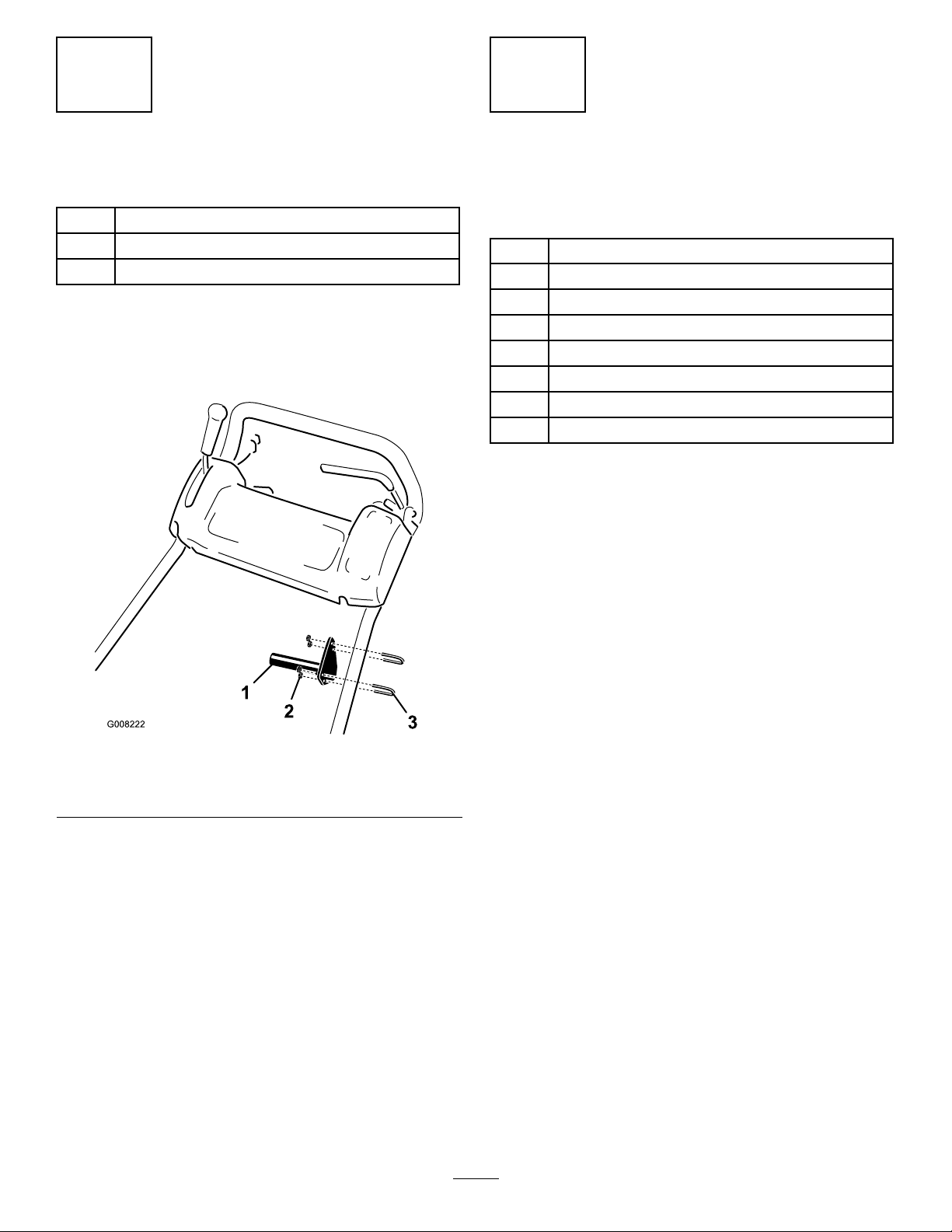
2
3
InstalltheLiftHandles
Partsneededforthisprocedure:
2
Lifthandle
4
Clamp
8Locknut
Procedure
1.Looselymountalifthandletoeachsideofthe
handlewith2clampsand4locknuts(Figure4).
InstallingtheKickstand(Model
04037Only)
Partsneededforthisprocedure:
1Kickstandassembly
2
Spring
2
Smallspacer
2Largespacer
2Largebolt
2
Smallbolt
2Locknut
2Washer
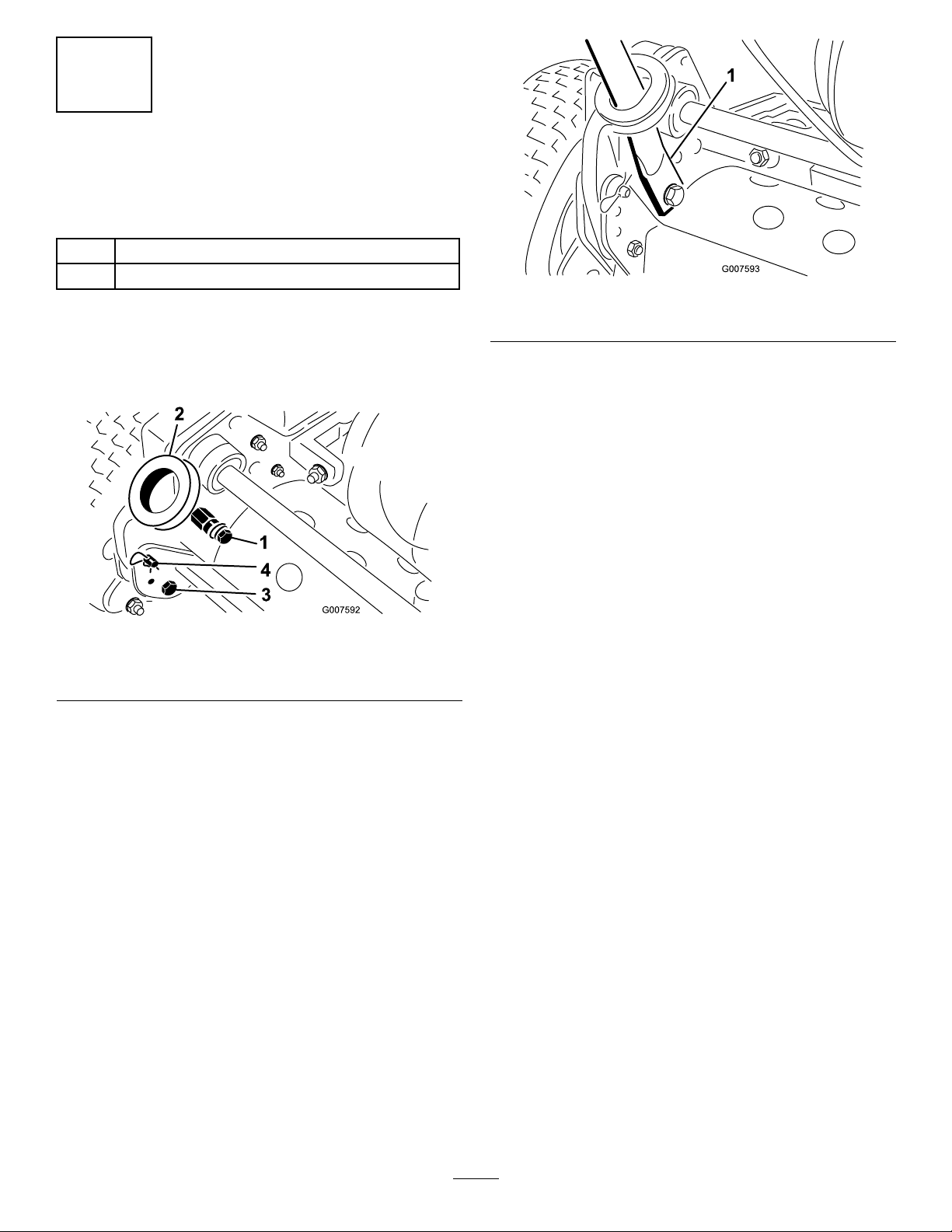
Procedure
1.Positionthekickstandbetweenthetabsontherear
oftheframe.
2.Installawasherontothesmallbolt.Installtheright
sideofthekickstandtotheframewiththeboltand
washer,thesmallspacer,andlocknut(
Ensuretheboltisinstalledfromtheinsideofthe
frameasshownin
Figure5.
Figure5).
Figure4
1.Lifthandle3.Clamp
2.Locknut
2.Positionthehandlesabout6inchesbelowthe
controlpanel(Figure4).Tightenthemountingnuts.
Note:Thelifthandlesmayberelocatedfor
operatorcomfort.
3.Securethecontrolcablestothehandle,belowthelift
handles,withcableties.
3.Installawasherontothelargebolt.
4.Installthespacerintothespringandinstallthelarge
boltintothespacer.
Important:Wheninstallingthespring,place
oneendofthespringundertherearframe
Figure5).
(
5.Installtheleftsideofthekickstandtotheframewith
theboltandwasher,thelargespacerandspring,and
locknut(Figure5).Ensuretheboltisinstalledfrom
theinsideoftheframeasshowninFigure5.
11
Page 12
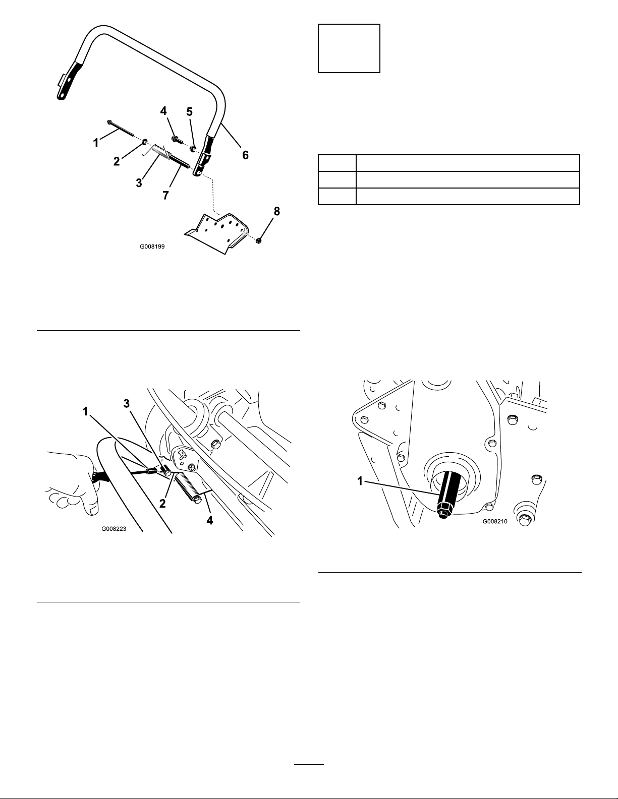
Figure5
1.Largebolt
2.Washer
3.Spring
4.Smallbolt
5.Smallspacer
6.Lefthandleend
7.Largespacer
8.Locknut
6.Placeanutrunnerovertheendofthespringpointing
towardstherearandmovetheendofthespringover
andunderthekickstandspacer(
Figure6).
4
InstallingtheTransport
Wheels
Partsneededforthisprocedure:
1
Wheelshaft,right
1
Wheelshaft,left
2
Transportwheels(obtainseparately)
Procedure
1.Pushthekickstanddownwithyourfootandpull
uponthehandletosupportthemoweronthekick
stand.
2.Apply#242Loctitetothethreadsofthewheel
shafts.
3.Threadtherightwheelshaftintothedrivepulleyon
therightsideofthemachine(
Note:Therightwheelshafthaslefthandthreads.
Figure7).
Figure6
1.Nutrunner3.Movethespringendunder
thekickstandspacer
2.Spring4.Springendunderframe
Figure7
1.Rightwheelshaft
4.Torquetheshaftto65to75ft-lb(88to101N-m).
5.Slidethewheelontotheaxle(Figure8).
6.Pivotthewheellockingclipawayfromcenterof
thewheelallowingittoslidefartherontotheaxle
(Figure8).
12
Page 13

Figure8
1.Lockingclip
7.Rotatewheelbackandforthuntilitslidescompletely
ontoaxleandlockingclipissecuredingrooveon
axleshaft.
6
InstallingtheGrassBasket
Partsneededforthisprocedure:
1
Grassbasket
Procedure
Graspbasketbytoplipandslideitontothebasket
mountingrods(Figure9).
8.Repeatprocedureonoppositesideofmachine.
9.Inatethetiresto12to15psi.(574to718Pa).
5
AdjustingtheCuttingUnit
NoPartsRequired
Procedure
Beforeoperatingthemachine,completethefollowing
adjustments:
•Levelthereardrumtothereel.
•Adjustthebedknifetothereel.
•Adjusttheheight-of-cut.
•Adjustthegrassshieldheight
1.Grassbasket
Figure9
2.Basketmountingrod
•Adjustthecutoffbar.
RefertotheCuttingUnitMaintenancesectionin
Maintenanceforinstructionsonperformingthese
procedures.
13
Page 14

ProductOverview
Controls
Figure10
1.Tractiondrivelever
2.Throttlecontrol5.Parkingbrake
3.On/offswitch
4.Servicebrake
theservicebraketoreleasetheparkingbrake.Youmust
releasethebrakebeforetractiondriveisengaged.
TractionDriveLever
Thetractiondrivelever(Figure10)islocatedonthe
frontrightsideofthecontrolpanel.Ithastwopositions:
NeutralandForward.Pushingtheleverforwardengages
thetractiondrive.
ThrottleControl
Thethrottlecontrol(Figure10)islocatedontopright
sideofthecontrolpanel.Theleverconnectstoand
operatesthrottlelinkagetothecarburetor.Theengine
speedcanbevariedfrom1600to3600RPM.
On/OffSwitch
Theon/offswitch(Figure10)islocatedonthetopof
thecontrolpanel.MoveswitchtotheOnpositionto
starttheengineandtheOffpositiontostoptheengine.
ServiceBrake
Theservicebrake(Figure10)islocatedontopleftside
ofcontrolpanel.Youcanusethebraketosloworstop
themachine.
Figure11
ReelDriveLever
Thereeldrivelever(Figure12)islocatedonthe
rightfrontcornerofthemachine.Theleverhastwo
positions:EngageandDisengage.Pulluponthelever
toengagethereelorpushitdowntodisengagethereel.
ParkingBrake
Theparkingbrake(Figure10&Figure11)islocatedat
thebaseoftheservicebrake.Fullyengagetheservice
brake,pushintheparkingbrakeknobandallowthe
servicebraketorestontheparkingbrakepin.Engage
Figure12
1.Reeldrivelever
14
Page 15

ChokeLever
Specications
Thechokelever(Figure13)islocatedonleftfrontof
theengine.Theleverhastwopositions:RunandChoke.
MovethelevertotheChokepositionwhenstarting
acoldengine.AfterenginestartsmovelevertoRun
position.
Figure13
1.Chokelever2.Fuelshutoffvalve
FuelShut-OffValve
Thefuelshutoffvalve(Figure13)islocatedonleft
frontofengine.Thevalvehastwopositions:Closed
andOpen.Movethelevertotheclosedpositionwhen
storingortransportingmachine.Openthevalvebefore
startingtheengine.
Model04036Model04037
Width
Height
Lengthwithbasket
Dryweight(with
basketandWiehle
roller;without
wheelsorgrooming
reel)
Widthofcut21inches(53cm)26inches(66cm)
Heightofcut1/8to1-1/4inches
Clip0.15inch(3.7mm)0.15inch(3.7mm)
EnginespeedLowidle–1600
36inches(91cm)41inches(104cm)
47inches(1 19cm)41-1/2inches
59inches(150cm)54-1/4inches
208lb(94kg.)229lb(104kg)
(0.3to3.2cm)
±100,Highidle–
3600±100
(105.4cm)
(137.8cm)
1/8to1-1/4inches
(0.3to3.2cm)
Lowidle–1600
±100,Highidle–
3600±100
Attachments/Accessories
AselectionofToroapprovedattachmentsand
accessoriesareavailableforusewiththemachineto
enhanceandexpanditscapabilities.Contactyour
AuthorizedServiceDealerorDistributororgoto
www.Toro.comforalistofallapprovedattachments
andaccessories.
RecoilStarter
Pullrecoilstarterhandle(Figure14)tostartengine.
Figure14
1.Recoilstarter2.Kickstand
Kickstand
Thekickstand(Figure14)ismountedtotherearof
machineandisusedtoraisetherearofmachinefor
installationorremovalofthetransportwheels.
15
Page 16

Operation
g014638
Note:Determinetheleftandrightsidesofthe
machinefromthenormaloperatingposition.
DANGER
Incertainconditions,gasolineisextremely
ammableandhighlyexplosive.Areorexplosion
fromgasolinecanburnyouandothersandcan
damageproperty.
ThinkSafetyFirst
Pleasecarefullyreadallofthesafetyinstructionsand
decalsinthesafetysection.Knowingthisinformation
couldhelpyouorbystandersavoidinjury.
CheckingtheEngineOilLevel
Checktheengineoillevelbeforeeachuseorevery8
operatinghours,refertoCheckingtheEngineOilLevel
EngineMaintenance(page22).
in
FillingtheFuelTank
Important:Neverusemethanol,gasoline
containingmethanol,gasoholcontainingmore
than10%ethanol,gasolineadditives,premium
gasoline,orwhitegasbecausethefuelsystem
couldbedamaged.Donotmixoilwithgasoline.
•Fillthefueltankoutdoors,inanopenarea,
whentheengineiscold.Wipeupanygasoline
thatspills.
•Neverllthefueltankinsideanenclosedtrailer.
•Donotllthefueltankcompletelyfull.Add
gasolinetothefueltankuntilthelevelis1inch
(2.5cm)belowthebottomofthellerneck.
Thisemptyspaceinthetankallowsgasoline
toexpand.
•Neversmokewhenhandlinggasoline,andstay
awayfromanopenameorwheregasoline
fumesmaybeignitedbyaspark.
•Storegasolineinanapprovedcontainerand
keepitoutofthereachofchildren.Neverbuy
morethana30daysupplyofgasoline.
•Donotoperatewithoutentireexhaustsystem
inplaceandinproperworkingcondition.
WARNING
Figure15
1.Fueltankcap
1.Cleanaroundfueltankcapandremovecapfrom
tank(Figure15).
2.Usingunleadedgasoline,llfueltanknohigher
thantobottomoflterscreen.Donotoverll.
3.Installfueltankcapandwipeupanyspilledgasoline.
Gasolineisharmfulorfatalifswallowed.
Long-termexposuretovaporscancauseserious
injuryandillness.
•Avoidprolongedbreathingofvapors.
•Keepfaceawayfromnozzleandgastankor
conditioneropening .
•Keepgasawayfromeyesandskin.
16
Page 17

DANGER
StartingandStoppingthe
Incertainconditionsduringfueling,static
electricitycanbereleasedcausingasparkwhich
canignitethegasolinevapors.Areorexplosion
fromgasolinecanburnyouandothersandcan
damageproperty.
•Alwaysplacegasolinecontainersontheground
awayfromyourvehiclebeforelling.
•Donotllgasolinecontainersinsideavehicle
oronatruckortrailerbedbecauseinterior
carpetsorplastictruckbedlinersmayinsulate
thecontainerandslowthelossofanystatic
charge.
•Whenpractical,removegas-powered
equipmentfromthetruckortrailerandrefuel
theequipmentwithitswheelsontheground.
•Ifthisisnotpossible,thenrefuelsuch
equipmentonatruckortrailerfromaportable
container,ratherthanfromagasolinedispenser
nozzle.
•Ifagasolinedispensernozzlemustbeused,
keepthenozzleincontactwiththerimofthe
fueltankorcontaineropeningatalltimesuntil
fuelingiscomplete.
CheckingtheInterlockSwitch
Operation
ServiceInterval:Beforeeachuseordaily
CAUTION
Ifsafetyinterlockswitchesaredisconnectedor
damagedthemachinecouldoperateunexpectedly
causingpersonalinjury.
•Donottamperwiththeinterlockswitches.
•Checktheoperationoftheinterlockswitches
dailyandreplaceanydamagedswitchesbefore
operatingthemachine.
1.Pushthekickstanddownwithyourfootandpull
upandbackonthehandletoraisethewheelsoff
oftheground.
2.PlacetractionleverintoEngagepositionandengine
controlsinstartingposition.
3.Attempttostartengine.
Theengineshouldnotstart.Ifenginestarts,the
interlockswitchneedsservice.Correctproblem
beforeoperating.RefertoServicingInterlock
Switch.
4.Carefullyliftuponhandletoreleasekickstand.
Engine
Note:Forillustrationsanddescriptionsofthecontrols
referencedinthissection,refertotheControlssection
inProductOverview.
StartingtheEngine
Note:Ensurethatthesparkplugwireisinstalledon
thesparkplug.
1.Ensurethatthetractionandreeldriveleversarein
theDisengagedposition.
Note:Theenginewillnotstartifthetractionlever
isintheEngagedposition.
2.Openthefuelshutoffvalveontheengine.
3.Movetheon/offswitchtotheOnposition.
4.MovethethrottlecontroltotheFastposition.
5.MovethechokeleverhalfwaybetweentheOnand
Offpositionswhenstartingacoldengine.The
chokemaynotberequiredwhenstartingawarm
engine.
6.Pulltherecoilstarterhandleoutuntilpositive
engagementresults,thenpullitvigorouslytostart
theengine.
Important:Donotpullrecoilropetoitslimit
orletgoofstarterhandlewhenropeispulled
outbecauseropemaybreakorrecoilassembly
maybedamaged.
7.MovethechoketotheOffpositionastheengine
warmsup.
StoppingtheEngine
1.Movethetractionandreeldrivecontrolstothe
Disengagedposition,thethrottlecontroltothe
Slowposition,andtheOn/OffswitchtotheOff
position.
2.Pullthesparkplugwireoffofthesparkplugto
preventthepossibilityofaccidentalstartingbefore
storingthemachine.
3.Closethefuelshutoffvalvebeforestoringor
transportingthemowerinavehicle.
DrivingtheMachinein
Transport
1.Pushthekickstanddownwithyourfootandpull
uponthehandletoraisetherearofmowerand
installthetransportwheels.
17
Page 18

2.Toreleasethekickstand,pulluponthehandle,
pushthemowerforward,andthenlowertherearof
mowerontothetransportwheels.
3.Ensurethatthetractionandreeldrivecontrolsare
intheDisengagedpositionandstarttheengine.
position,stoptheengineandpushthereeldrive
leverintotheDisengageposition.
5.Emptythegrassbasketofclippings,installthegrass
basket,andcommencetransportoperation.
4.SetthethrottlecontroltoSlow ,raisethefrontofthe
machineupslightly,graduallyengagethetraction
driveandslowlyincreasetheenginespeed.
5.Adjustthethrottletooperatethemoweratthe
desiredgroundspeedandtransportthemowerto
thedesireddestination.
PreparingtoMow
1.ReturnthetractioncontrollevertotheDisengage
position,thethrottletotheSlowposition,andstop
theengine.
2.Pushthekickstanddownwithyourfootandpull
upandbackonthehandletoraisethewheelsoff
oftheground.
3.Pushthelockingclipsonthewheelsoutofthe
groovesintheshafts.
4.Slidethewheelsoffoftheshafts.
5.Movetheunitoffofthekickstand.
OperatingTips
BeforeMowing
•Ensurethatthemoweriscarefullyadjustedand
issetevenlyonbothsidesofthereel.Improper
moweradjustmentismagniedmanytimesoverin
theappearanceoftheclippedturf.
•Removeallforeignobjectsfromtheturfpriorto
mowing.
•Ensurethateveryone,especiallychildrenandpets,
areclearoftheworkarea.
MowingT echniques
•Mowagreeninastraightbackandforthdirection,
acrossthegreen.
•Avoidcircularmowingorturningthemowerona
greenbecausescufngmayoccur.Turnthemower
offofthegreenbyraisingthecuttingreel(pushing
thehandledown)andturningonthetractiondrum.
Mowing
Properuseofthemachineprovidesthesmoothest
turfcuttingavailable.ReferalsotoOperatingTips
forfundamentalsuggestionstoobtaintheutmost
performancefromyourmower.
Important:Excessiveoperationofthecuttingunit
withtheabsenceofgrassclippings(lubricant)can
damagethecuttingunit.
1.Starttheengine,setthethrottleatreducedspeed,
pushdownonthehandletoraisethecuttingunit,
movethetractionlevertotheEngagedposition,
andtransportthemowerontocollarofthegreen.
2.MovethetractionlevertotheDisengagedposition
andmovethereeldrivelevertotheEngaged
position.
3.MovethetractionlevertotheEngagedposition,
increasethethrottlespeeduntilthemoweris
travelingatthedesiredgroundspeed,drivethe
mowerontothegreen,lowerthefrontofthe
mower,andcommenceoperation.
•Mowatanormalwalkingpace.Fastspeedsaves
verylittletimeandwillresultinaninferiormowing
job.
4.Whennishedmowing,driveoffofthegreen,
movethetractioncontrollevertotheDisengage
18
Page 19

Maintenance
Note:Determinetheleftandrightsidesofthemachinefromthenormaloperatingposition.
RecommendedMaintenanceSchedule(s)
MaintenanceService
Interval
Aftertherst8hours
Aftertherst25hours
Beforeeachuseordaily
Every25hours
Every50hours
Every100hours
Every200hours
Every300hours
Beforestorage
Important:Refertoyour
MaintenanceProcedure
•Changetheengineoil.
•Cleanthefuellter.
•Checktheinterlockswitchoperation.
•Checktheengineoillevel.
•Greasethemachine.(Greasethettingsimmediatelyaftereverywashingregardless
oftheintervallisted.)
•Cleanandoiltheaircleanerfoamelement.(Moreoftenindirtyordustyconditions)
•Changetheengineoil.(Morefrequentlyindustyordirtyconditions)
•Cleanthefuellter.
•Cleanorreplacethepaperairlterelement.(Moreoftenindirtyordustyconditions)
•Checkthesparkplug.
•Decarbontheengine.
•Changetheairlterpaperelement
•Checktheconditionandtensionofbelts.
•Paintchippedsurfaces.
•RefertoStorageSectionforadditionalinformation
Engine Operator’ s Man ual
foradditionalmaintenanceprocedures.
19
Page 20

DailyMaintenanceChecklist
Important:Duplicatethispageforroutineuse.
Maintenance
CheckItem
Checkthe
safetyinterlock
operation.
Checktheparking
brakeoperation.
Checkthefuel
level.
Checktheengine
oillevel.
Checktheair
lter.
Cleantheengine
coolingns.
Checkforunusual
enginenoises.
Checkforunusual
operatingnoises.
Checkthe
reel-to-bedknife
adjustment.
Checkthe
height-of-cut
adjustment.
Greaseallttings.
Touchup
damagedpaint.
Fortheweekof:
Mon.Tues.Wed.Thurs.Fri.
Sat.Sun.
NotationforAreasofConcern
Inspectionperformedby:
ItemDate
Information
20
Page 21

Lubrication
GreasingtheMachine
ServiceInterval:Every25hours
Lubricatethe13greasettingsonthemowerusing
aNo.2multipurposelithiumbasegrease.Ahand
operatedgreasegunisrecommendedforbestresults.
Thegreasettinglocationsareasfollows:
•2onthefrontroller(Figure16)
•2onthereelbearings(Figure16)
•2onthedrumaxles(Figure17)
•3onthedifferential(
•2onthereelcountershaftbearings(Figure18)
•2onthebeltidlerpivots(Figure19).
1.Wipeeachgreasettingwithacleanrag.
2.Pumpgreaseintoeachttinguntilitbeginstoget
difculttopumpthegun.
Important:Donotapplytoomuchpressureor
greasesealswillbecomepermanentlydamaged.
3.Wipeoffexcessgrease.
Figure17)
Figure18
Figure19
Figure16
Figure17
21
Page 22

EngineMaintenance
ServicingtheEngineOil
ServiceInterval:Aftertherst8hours—Changethe
engineoil.
Beforeeachuseordaily—Checkthe
engineoillevel.
Every50hours—Changetheengine
oil.(Morefrequentlyindustyordirty
conditions)
Crankcasecapacity:20oz.(.59l)
Theengineusesanyhigh-qualityoilhavingtheAmerican
PetroleumInstitute-APl-“serviceclassication"SF,
SG,SHorSJ .Oilviscosity-weight-mustbeselected
accordingtoambienttemperature.illustratesthe
temperature/viscosityrecommendations.
Figure20
Figure21
1.Oillevelgauge
2.Removetheoillevelgaugebyrotatingit
counterclockwise.
3.Wipetheoillevelgaugecleanandinsertitintothe
llerport.Donotscrewitintotheport.
4.Removethegaugeandchecktheleveloftheoil.
5.Ifthelevelislow,addonlyenoughoiltoraisethe
leveluntilitisbetweenthe“H”and“L”markson
thegauge(
Figure22).Donotoverll.
2.Drainplug
Note:Usingmultigradeoils(5W-20,10W-30,and
10W-40)willincreaseoilconsumption.Checktheoil
levelmorefrequentlywhenusingthem.
CheckingtheEngineOilLevel
1.Positionmowersotheengineislevelandclean
aroundoillevelgauge(Figure21).
Figure22
6.Installtheoillevelgaugeandwipeupanyspilledoil.
ChangingtheEngineOil
1.Startandruntheengineforafewminutestowarm
theengineoil.
2.Placeadrainpanattherearofmachine,underthe
drainplug(
3.Removethedrainplug.
22
Figure21).
Page 23

4.Pushdownonthehandletotipthemowerandthe
enginebackward,allowingmoreoiltorunintothe
drainpan.
5.Installthedrainplugandrellthecrankcasewiththe
properoil;refertoCheckingtheEngineOilLevel.
ServicingtheAirCleaner
ServiceInterval:Every25hours—Cleanandoiltheair
cleanerfoamelement.(Moreoftenin
dirtyordustyconditions)
Every100hours—Cleanorreplace
thepaperairlterelement.(More
oftenindirtyordustyconditions)
Every300hours—Changetheair
lterpaperelement
Important:Servicetheaircleanermoreoftenin
dirtyordustyconditions
1.Makesurethewireisoffofthesparkplug.
2.Removethewingnutssecuringtheaircleanercover
andremovethecover(
Figure23).
Figure24
1.Foamelement2.Paperelement
5.Checkconditionofthepaperelement.Cleanby
gentlytappingthelterorreplaceitasrequired.
Important:Donotusecompressedairtoclean
thepaperelement.
6.Installthefoamelement,paperelement,andair
cleanercover.
Important:Donotoperatetheenginewithout
theaircleanerelementbecauseextremeengine
wearanddamagewilllikelyresult.
Figure23
1.Aircleanercover
3.Cleanthecoverthoroughly .
4.Ifthefoamelementisdirty,removeitfromthepaper
element(Figure24)andcleanthoroughly,asfollows:
A.Washthefoamelementinasolutionofliquid
soapandwarmwater.Squeezeittoremovedirt,
butdonottwistitbecausethefoammaytear.
B.Drythefoamelementbywrappingitinaclean
rag.Squeezetheragandfoamelementtodry
it,butdonottwistit.
C.Saturatethefoamelementwithcleanengineoil.
Squeezetheelementtoremoveexcessoiland
todistributetheoilthoroughly.Anoildamp
elementisdesirable.
ReplacingtheSparkPlug
ServiceInterval:Every100hours
UseanNGKBPR5ESsparkplugorequivalent.The
correctairgapis0.028-0.032inch.
1.Pullthemoldedwireoffofthesparkplug(Figure25).
Figure25
1.Sparkplugwire
2.Cleanaroundthesparkplugandremoveitfromthe
cylinderhead.
Important:Replaceacracked,fouled,ordirty
sparkplug.Donotsandblast,scrape,orclean
electrodesbecauseenginedamagecouldresult
fromgritenteringthecylinder.
23
Page 24

3.Settheairgapat0.028to0.032inch(0.05to0.07
cm)(Figure26).
FuelSystem
Maintenance
CleaningtheFuelFilter
ServiceInterval:Aftertherst25hours
Every50hours
Figure26
4.Installthecorrectlygappedsparkplugandtighten
itto17ft.-lb(23N-m).
5.Installthesparkplugwireonthesparkplug.
1.Closethefuelshutoffvalveandunscrewthebowl
fromthelterbody(
1.Shutoffvalve
2.Cleanthebowlandlterincleangasolineandinstall
it.
Figure27).
Figure27
2.Bowl
24
Page 25

ElectricalSystem
Maintenance
BrakeMaintenance
AdjustingtheService/Parking
ServicingtheInterlockSwitch
Usethefollowingprocedureiftheswitchneeds
adjustmentorreplacement.
1.Makesuretheengineisoffandthetractionlever
isdisengagedandrestingagainsttheneutralstop
Figure28).
(
Brake
Ifservice/parkingbrakeslipswhenoperated,an
adjustmentisrequired.
1.Engagetheservicebrake,pushinontheparking
brakeknobandallowtheservicebraketorestonthe
parkingbrakepin(
Figure29).
Figure28
1.Tractionlever3.Interlockswitch
2.Neutralstop
2.Loosentheinterlockswitchmountingfasteners
(Figure28).
3.Placea.032"thickshimbetweenthetractionlever
andtheinterlockswitch(Figure28).
4.Tighteninterlockswitchmountingfasteners.
Recheckgap.Thetractionlevermustnotcontact
theswitch.
5.Engagetractionleverandverifythattheswitchloses
continuity.Replaceifrequired.
4..032"Gap
Figure29
2.Usingaspringscale,pressrearwardontheservice
brakelever(Figure30).Theparkingbrakeshould
releasewhenaforceof30to40poundsisattained.
Iftheparkingbrakereleasesbefore30to40pounds
offorceisattained,anadjustmenttothebrakecable
isrequired.Proceedtostep3.
25
Page 26

Figure30
1.Rearpressureonservicebrakelever
(Bracketatthebaseoftheengineshown)
1.Service/parkingbrake
cable
Figure32
2.Frontjamnut
3.LoosentheretainersecuringtheV-beltcoverand
pivotthecoveropen(Figure31).
Figure31
1.V-beltcover2.Retainer
4.Toadjustthebrakecabletension,proceedasfollows.
•Todecreasethecabletension,loosenthefront
cablejamnutandtightentherearjamnut
Figure32).Repeatstepsoneandtwoand
(
readjustifrequired.
•Toincreasethecabletension,tightenthefront
cablejamnutandloosentherearjamnut
Figure32).Repeatstepsoneandtwoand
(
readjustifrequired.
5.Closethecoverandsecuretheretainer.
Note:Theadjustmentscanbeperformedon
thecableatthejamnutbracketsbythecontrol
paneloratthebracketatthebaseoftheengine.
26
Page 27

BeltMaintenance
Important:Donotovertensionthebelt.
B.Tightenthenuttolocktheadjustment.
AdjustingtheBelts
ServiceInterval:Every300hours—Checkthe
conditionandtensionofbelts.
Ensurethatthebeltsareproperlytensionedtoensure
properoperationofthemachineandunnecessarywear.
Checkbeltsfrequently.
AdjustingtheReelDriveBelt
1.Removethebeltcovermountingfastenersandbelt
covertoexposethebelt(
Figure33).
4.Installthebeltcoverbyplacingitinposition.
5.Whilemaintainingaslightgapbetweenthecover
sealandthesideplate,installeachmountingbolt
untilthethreadsengageintheinsert.Thegapallows
visualalignmentoftheboltstothethreadedinserts.
6.Afterallboltsareinstalled,tightenthemuntilthe
standoffsinsidethecovercontactthesideplate.Do
notovertighten.
AdjustingtheTractionDriveBelt
1.Removethebeltcovermountingfastenersandthe
beltcovertoexposethebelt(Figure35).
Figure33
1.Beltcover
2.Checkthetensionbypressingthebeltatmidspan
ofthepulleys(Figure34)with4to5lbofforce.The
beltshoulddeect1/4inch.
Figure34
1.Reeldrivebelt2.Idlerpulley
3.Completethefollowingtoadjustthebelttension:
Figure35
1.Tractiondrivebeltcover
2.Checkthetensionbypressingthebeltatmidspan
ofthepulleys(Figure36)with4to5lbofforce.The
beltshoulddeect1/4inch.
Figure36
1.Tractiondrivebelt2.Idlerpulley
A.Loosentheidlerpulleymountingnutandpivot
theidlerpulleydownwardagainstthebacksideof
thebeltuntilyouattainthedesiredbelttension
(Figure34).
3.Completethefollowingtoadjustthebelttension:
A.Loosentheidlerpulleymountingnutandpivot
theidlerpulleyclockwiseagainstthebacksideof
27
Page 28

thebeltuntilthedesiredbelttensionisattained
(Figure36).
Important:Donotovertensionthebelt.
B.Tightenthenuttolocktheadjustment.
4.Installthebeltcoverbyplacingitinposition.
5.Whilemaintainingaslightgapbetweenthecover
sealandthesideplate,installeachmountingbolt
untilthethreadsengageintheinsert.Thegapallows
visualalignmentoftheboltstothethreadedinserts.
6.Afterallboltsareinstalled,tightenthemuntilthe
stand-offsinsidethecovercontactthesideplate.Do
notovertighten.
AdjustingtheDifferentialBelt
1.Removetheboltssecuringthefrontandrearsections
ofthedifferentialcovertothedifferentialhousing
andslidethecoversectionsawaytoexposethebelt.
2.Checkthetensionbypressingthebeltatmidspan
ofthepulleys(Figure37)with5to6lbofforce.The
beltshoulddeect1/4inch.
AdjustingthePrimaryV-Belts
1.ToadjustthebelttensiononprimaryV-belts,rst
checktheadjustmentofthetractioncontrol.Refer
toAdjustingtheTractionControl.Ifunabletoattain
the4to5lbforcerequiredinadjustingthetraction
control,proceedtonextstep.
2.LoosentheretainersecuringtheV-beltcoverand
pivotthecoveropen(
1.V-beltcover2.Retainer
Figure38).
Figure38
Figure37
1.Differentialbelt
2.Idlerpulley
3.Completethefollowingtoadjustthebelttension:
A.Loosentheidlerpulleymountingnutandpivot
theidlerpulleyclockwiseagainstthebacksideof
thebeltuntilthedesiredbelttensionisattained
Figure37).
(
Important:Donotovertensionthebelt.
B.Tightenthenuttolocktheadjustment.
4.Installthebeltcoverbyplacingitinposition.
5.Whilemaintainingaslightgapbetweenthecover
sealandthesideplate,installeachmountingbolt
untilthethreadsengageintheinsert.Thegapallows
visualalignmentoftheboltstothethreadedinserts.
6.Afterallboltsareinstalled,tightenthemuntilthe
stand-offsinsidethecovercontactthesideplate.Do
notovertighten.
3.Toincreasebelttension,loosentheenginemounting
boltsandmoveenginebackwardsintheslots.
Important:Donotovertensionthebelt.
4.Tightenthemountingbolts.
Note:Thedistancebetweenthecentersofthe
driverandthedrivenpulleysshouldbeapproximately
5.18inches(13.15cm)afternewV-beltsareinstalled.
5.AftertensioningtheprimaryV-belts,checkthe
alignmentoftheengineoutputshaftpulleyandthe
countershaftpulleywithastraightedge.
6.Ifthepulleysaremisaligned,loosenthescrews
securingtheenginemountingbasetothemower
frameandslidetheenginefromsidetosideuntilthe
pulleysarealignedwithin0.030inch(0.07cm).
28
Page 29

Figure39
1.PrimaryV-belts3.Idlerpulley
2.Beltguide
1.Differentialcoversections
2.Frontclutchhousing
Figure40
3.Rightrearbearinghousing
7.Tightenthemountingscrewsandcheckthe
alignment.
8.Topushorpullthemachineeasierwithoutstarting
theengine,adjustthebeltguide(Figure39,inset)
asfollows:
A.Engagetheclutch.
B.Loosenthenutsecuringtheidlerpulleyandbelt
guidetotheidlerarm.
C.Rotatethebeltguideclockwiseuntilagapof
approximately0.06inch(0.15cm)isobtained
betweentheguidengerandthebacksideofthe
drivebelts.
D.Tightentheboltandlocknutsecuringtheidler
pulleyandbeltguidetotheidlerarm.
9.Closethecoverandsecuretheretainer.
ReplacingtheDifferentialBelt
1.Removetheboltssecuringthetractiondriveandreel
drivebeltcoverstotherightsideplateandremove
thebeltcovers.
5.Loosentheidlerpulleymountingnutonthe
differentialidlerpulleyandpivottheidlerpulley
counterclockwiseawayfromthebacksideofthebelt
toreleasethebelttension.
6.Removethe2boltsandlocknutssecuringthefront
clutchhousingtothesideplate(
Figure40).
7.Rotatethehousing180°sothebottomofthe
housingpointsupward.
8.Removethe2boltsandlocknutssecuringtheright
rearbearinghousingtothesideplate(
Figure40).
9.Rotatethehousing180°sothebottomofthe
housingpointsupward.Removeoldbelt.
10.Slidethenewbeltovertherotatedhousingcovers,
thedifferentialcoversections,andontothe
differentialpulleys.
11.Ensurethattheidlerpulleyispositionedagainstthe
backsideofbelt.
12.Rotatebothhousingsbackintotheuprightposition
andsecurethemtothesideplatewiththeboltsand
nutspreviouslyremoved.
2.Loosentheidlerpulleymountingnut,oneachidler
pulley,andpivoteachidlerpulleycounterclockwise
awayfromthebacksideofeachbelttoreleasebelt
tension.
3.Removethebelts.
4.Removetheboltssecuringthefrontandrearsections
ofthedifferentialcovertothedifferentialhousing
andslidethecoversectionsawaytoexposethebelt
(Figure40).
13.Adjustthedifferentialbelttension;refertoAdjusting
theDifferentialBelt.
14.Adjustthebelttensiononthetractiondriveandreel
drivebelts;refertoAdjustingtheTractionDrive
Belt,andAdjustingtheReelDriveBelt
15.Installthedifferential,tractiondrive,andreeldrive
covers.
29
Page 30

ControlsSystem
Maintenance
CuttingUnitMaintenance
LevelingtheRearDrumtothe
AdjustingtheTractionControl
Iftractioncontroldoesnotengageoritslipsduring
operation,anadjustmentisrequired.
1.MovethetractioncontroltotheDisengaged
position.
2.LoosentheretainersecuringtheV-beltcoverand
pivotthecoveropen(
3.Toincreasethecabletension,loosenthefront
cablejamnutandtightenthebackcablejamnut
(Figure41)untilaforceof7to9lbisrequiredto
engagethetractioncontrol.Measuretheforceatthe
controlknob.
Figure38).
Reel
1.Positionthemachineonaat,levelsurface,
preferablyaprecisionsteelworkplate.
2.Placea1/4x1inch(0.6x2.5cm)atsteelstrip,
approximately29inches(73.6cm)long,underthe
reelbladesandagainstthefrontedgeofthebedknife
topreventthebedbarfromrestingonthework
surface.
3.Raisethefrontrollersoonlythereardrumandreel
areonthesurface.
4.Firmlypressdownonthemachineabovethereelso
allreelbladescontactthesteelstrip.
5.Whilepressingdownonthereel,slideafeelergauge
underoneendofthedrum,thenchecktheother
endofthedrum.
Ifthereisagapbetweenthedrumandthework
surface,greaterthan0.010inch(.025cm),oneither
end,adjustthedrum(proceedtostep6).Ifthegap
islessthan0.010inch(.025cm)noadjustmentis
required.
Figure41
1.Tractioncable2.Frontjamnut
4.Tightenfrontcablejamnut.
5.Closethecoverandsecuretheretainer.
6.Checkthetractioncontroloperation.
6.Removetherearbeltcoverfromtherightsideof
themachine(
1.Tractiondrivebeltcover
7.Rotatethedrivenpulleyuntiltheholesalignwiththe
4rollerbearingangescrews(Figure43).
Figure42).
Figure42
30
Page 31

Figure43
1.Drivenpulley3.IdlerPulley
2.4holes
8.Loosenthe4rollerbearingscrewsandthescrew
securingtheidlerpulley .
9.Raiseorlowertherightsideoftherollerassembly
untilthegapislessthan0.010inch(.025cm).
10.Tightentherollerbearingscrews.
11.Adjustthebelttensionandtightentheidlerpulley
mountingscrew(Figure43).
AdjustingtheBedknifetothe
Reel
Thebedknifetoreeladjustmentisaccomplishedby
looseningortighteningthebedbaradjustingscrews,
locatedontopofthemower.
1.Positionthemachineonaat,levelworksurface.
2.Ensurethatthereelcontactisremovedbyturning
thebedbaradjustingscrewscounterclockwise
(Figure44).
sameendofreel,oneclickatatime,untilthepaper
ispinchedlightly,wheninsertedfromthefront,
paralleltothebedknife,whichresultsinaslightdrag
whenpaperispulled(
Note:Eachtimetheadjustingscrewisrotatedone
clickclockwise,thebedknifemoves0.0007inch
(0.0017cm)closertothereel.Donotovertighten
theadjustingscrews.
5.Checkforlightcontactattheotherendofthereel
usingpaperandadjustitasrequired.
6.Aftertheadjustmentisaccomplished,checktosee
ifthereelcanpinchpaperwheninsertedfromthe
frontandcutpaperwheninsertedatarightangleto
thebedknife(
paperwithminimumcontactbetweenthebedknife
andthereelblades.Shouldexcessivereeldragbe
evident(morethan7inch-lb(0.79N•m),either
backlaporgrindthecuttingunittoachievethesharp
edgesneededforprecisioncutting;refertotheToro
reelsharpeningmanual.
Figure45).Itshouldbepossibletocut
Figure44)
Figure45
AdjustingtheHeightofCut
Figure44
1.Bedbaradjustingscrew
3.Tiltthemowerbackonthehandletoexposethe
bedknifeandreel.
4.Ononeendofthefrontsideofthereel,insertalong
stripofnewspaperbetweenthereelandbedknife
(Figure45).Whileslowlyrotatingthereelforward,
turnthebedbaradjustingscrewclockwise(onthe
1.Verifythattherearrollerislevelandthatthe
bedknifetoreelcontactiscorrect.Tipthemower
backonthehandletoexposethefrontandrear
rollersandthebedknife.
2.Loosenthelocknutssecuringtheheight-of-cutarms
totheheight-of-cutbrackets(Figure46).
31
Page 32

Figure46
1.Height-of-cutarm
2.Height-of-cutbracket
3.Locknut
4.Adjustingscrew
3.Loosenthenutonthegaugebar(Figure47)andset
theadjustingscrewtothedesiredheight-of-cut.The
distancebetweenthebottomofthescrewheadand
thefaceofthebaristheheight-of-cut.
ensurestheheight-of-cutisidenticalatboth
endsofthebedknife.
7.Tightennutstolocktheadjustment.
Important:T oavoidscalpingonundulating
turf,ensurethattherollersupportsare
positionedrearward(therollerclosertothereel).
Note:Thefrontrollercanbeputinthreedifferent
positions(
Figure49),dependingontheapplication
andneedsoftheuser.
•Usethefrontpositionwhenagroomeris
installed.
•Usethemiddlepositionwithoutagroomer.
•Usethethirdpositioninextremelyundulating
turfconditions.
Figure47
1.Gaugebar
2.Heightadjustingscrew
3.Nut
4.Hookthescrewheadonthecuttingedgeofthe
bedknifeandresttherearendofthebarontherear
roller(
Figure48).
Figure48
5.Rotatetheadjustingscrewuntiltherollercontacts
thefrontofthegaugebar.
6.Adjustbothendsoftherolleruntiltheentireroller
isparalleltothebedknife.
Figure49
AdjustingtheGrassShield
Height
Adjusttheshieldtoensurepropergrassclipping
dischargeintothebasket.
1.Measurethedistancefromtopofthefrontsupport
rodtothefrontlipoftheshieldateachendofthe
cuttingunit(Figure50).
Figure50
1.Supportrod2.Shield
Important:Whensetproperly,therearand
frontrollerswillcontactthegaugebarandthe
screwwillbesnugagainstthebedknife.This
2.Theheightoftheshieldfromthesupportrodfor
normalcuttingconditionsshouldbe4inches(10
cm).Loosentheboltsandnutssecuringeachendof
32
Page 33

theshieldtothesideplateandadjusttheshieldto
thecorrectheight.
3.Tightenthefasteners.
Note:Theshieldcanbeloweredfordrier
conditions(clippingsyovertopofbasket)orraised
toallowforheavywetgrassconditions(clippings
builduponrearofbasket).
AdjustingtheCut-OffBar
Adjustthecut-offbartoensurethattheclippingsare
cleanlydischargedfromthereelarea.
BedbarIdentication
Todetermineifthebedbarisstandardoraggressive,
checktheleftbedbarmountingears.Ifthemounting
earsareroundeditisastandardbedbar.Ifthemounting
earshaveanotchinthem,itisanaggressivebedbar
(Figure52).
1.Loosenthescrewssecuringthetopbar(
Figure51)
tocuttingunit.
Figure51
1.Cut-offbar
2.Inserta0.060inch(0.15cm)feelergaugebetween
thetopofthereelandthebarandtightenthescrews.
3.Ensurethatthebarandreelareequaldistanceapart
acrosstheentirereel.
Note:Thebarisadjustabletocompensatefor
changesinturfconditions.Adjustthebarcloserto
thereelwhentheturfisextremelywet.Bycontrast,
adjustthebarfurtherawayfromthereelwhenturf
conditionsaredry.Thebarshouldbeparalleltothe
reeltoensureoptimumperformance.Adjustthebar
whenevertheshieldheightisadjustedorwhenthe
reelissharpenedonareelgrinder.
1.Standardbedbar
Figure52
2.Aggressivebedbar
33
Page 34

SettingtheMachinetoMatch
TurfConditions
Usethefollowingtabletosetthemachinetomatch
turfconditions.
GreensmowerCuttingUnitSetUpMatrix
Bedbars:StandardandOptional
PartNumberDescriptionMowerAggressiveness
112-9281-01
112-9279-03Aggressive
112-9280-01
110-9278-03Aggressive
Bedknives:StandardandOptional
PartNumberDescriptionMower
93-4262Microcut
93-4263T ournament
93-4264
112-9275Microcut
94-5885T ournament
104-2646
StandardGreensmaster2000
Greensmaster2000
StandardGreensmaster2600
Greensmaster2600
Greensmaster2000
Greensmaster2000
LowCutGreensmaster2000
Greensmaster2600
Greensmaster2600
HighCutGreensmaster2600
Less
More
Less
More
HeightofCutRangeComments
<0.125inches
0.125-0.25inches
0.25inchesandup
<0.125inches
0.125-0.25inches
0.25inchesandupTees
Comments
StandardGreensmaster2000
StandardGreensmaster2600
StandardGreensmaster2000
StandardGreensmaster2600
93-9015
Rollers:StandardandOptional
PartNumberDescriptionMower
99-6241NarrowWiehle
88-6790WideWiehle
104-2642FullRoller
71-1550WiehleRoller
93-9045WiehleRoller
52-3590
93-9039NarrowWiehle
95-0930FullRoller
ClipKit
PartNumberDescriptionMower
65–9000
LowCutGreensmaster2600
SwagedRollerGreensmaster2000
ClipKitGreensmaster2000
0.25inchesandup
Diameter/MaterialComments
Greensmaster2000
Greensmaster2000
Greensmaster20002.0"Steel
Greensmaster20002.0inchesCastIron
Greensmaster2000
Greensmaster2600
Greensmaster26002.5inchesSteel
&Greensmaster
2600
2.0inchesAluminum
2.0inchesAluminumMorePenetration,0.43
2.5inchesAluminum
2.5inchesAluminum
2.5inchesAluminum
Standard,0.2Spacing
Spacing
LeastPenetration
MorePenetration,0.43
Spacing
24inchesWideforEdge
Support
Standard
LeastPenetration
Comments
Decreaseclipto0.25"
34
Page 35

ServicingtheBedbar
BacklappingtheReel
RemovingtheBedbar
1.Turnbedbaradjusterscrew,counterclockwise,to
backbedknifeawayfromreel(Figure53).
Figure53
1.Bedbaradjustingscrew3.Bedbar
2.Springtensionnut
2.Backoutthespringtensionnut,untilthewasheris
nolongertensionedagainstthebedbar(Figure53).
3.Oneachsideofthemachine,loosenthejamnut
securingthebedbarbolt(Figure54).
1.Removetheplugintherightreeldrivecover
(Figure55).
Figure55
1.Coverplug
2.Inserta1/2inchsocketextension,connectedtothe
backlappingmachine,intothesquareholeinthe
centerofthereelpulley .
3.BacklapaccordingtotheprocedureintheToro
SharpeningReelandRotaryMowersManual,FormNo.
80-300PT .
Figure54
1.Jamnut2.Bedbarbolt
4.Removeeachbedbarboltallowingthebedbartobe
pulleddownwardandremovedfromthemachine.
Savethe2nylonand2stampedsteelwasherson
eachendofbedbar(
Figure54).
InstallingtheBedbar
1.Installthebedbar,positioningthemountingears
betweenthewasherandthebedbaradjuster.
2.Securethebedbartoeachsideplatewiththebedbar
bolts(jamnutsonthebolts)and8washers.Position
anylonwasheroneachsideofthesideplateboss.
Placeasteelwasheroutsideeachofthenylon
washers.
3.Torqueboltsto240to320inch-lb(27to36N-m).
4.Tightenthejamnutsuntilthethrustwashersjust
rotatefreely .
5.Tightenthespringtensionnutuntilthespringis
collapsed,thenbackitoff1/2turn.
6.Adjustthebedbar;refertoAdjustingtheBedknife
totheReel.
DANGER
Contactwiththereelorothermovingpartscan
resultinpersonalinjury.
•Stayawayfromthereelwhilebacklapping.
•Neveruseashorthandledpaintbrushfor
backlapping.PartNo.29-9100Handle
assemblycompleteorindividualpartsare
availablefromyourlocalAuthorizedT oro
Distributor.
Note:Forabettercuttingedge,runaleacross
thefrontfaceofthebedknifewhenthelapping
operationiscompleted.Thiswillremoveanyburrs
orroughedgesthatmayhavebuiltuponthecutting
edge.
4.Installthepluginthecoverwhennished.
35
Page 36

Storage
1.Removegrassclippings,dirt,andgrimefromthe
externalpartsoftheentiremachine,especiallythe
engine.Cleandirtandchafffromtheoutsideofthe
engine’scylinderheadnsandblowerhousing.
Important:Youcanwashthemachinewith
milddetergentandwater.Donotpressurewash
themachine.Avoidexcessiveuseofwater,
especiallyneartheshiftleverplate,andengine.
2.Forlong-termstorage(morethan90days)add
stabilizer/conditioneradditivetofuelinthetank.
A.Runtheenginetodistributeconditionedfuel
throughthefuelsystem(5minutes).
B.Eitherstopengine,allowittocool,anddrainthe
fueltank,oroperatetheengineuntilitstops.
C.Restarttheengineandrunituntilitstops.
Repeat,onChoke,untiltheenginewillnot
restart.
D.Disposeoffuelproperly.Recycleasperlocal
codes.
Note:Donotstorestabilizer/conditioned
gasolineover90days.
3.Checkandtightenallbolts,nuts,andscrews.Repair
orreplaceanypartthatisdamagedordefective.
4.Paintallscratchedorbaremetalsurfaces.Paintis
availablefromyourAuthorizedServiceDealer.
5.Storethemachineinaclean,drygarageorstorage
area.Coverthemachinetoprotectitandkeepit
clean.
36
Page 37

Notes:
37
Page 38

Notes:
38
Page 39

Notes:
39
Page 40

TheToroT otalCoverageGuarantee
ALimitedWarranty
ConditionsandProductsCovered
TheToro
toanagreementbetweenthem,jointlywarrantyourT oroCommercial
product(“Product”)tobefreefromdefectsinmaterialsorworkmanship
fortwoyearsor1500operationalhours*,whicheveroccursrst.This
warrantyisapplicabletoallproductswiththeexceptionofAerators
(refertoseparatewarrantystatementsfortheseproducts).Wherea
warrantableconditionexists,wewillrepairtheProductatnocosttoyou
includingdiagnostics,labor,parts,andtransportation.Thiswarranty
beginsonthedatetheProductisdeliveredtotheoriginalretailpurchaser.
*Productequippedwithanhourmeter.
®
Companyanditsafliate,ToroWarrantyCompany,pursuant
InstructionsforObtainingWarrantyService
YouareresponsiblefornotifyingtheCommercialProductsDistributoror
AuthorizedCommercialProductsDealerfromwhomyoupurchasedthe
Productassoonasyoubelieveawarrantableconditionexists.Ifyouneed
helplocatingaCommercialProductsDistributororAuthorizedDealer,or
ifyouhavequestionsregardingyourwarrantyrightsorresponsibilities,
youmaycontactusat:
CommercialProductsServiceDepartment
ToroWarrantyCompany
811 1LyndaleAvenueSouth
Bloomington,MN55420-1196
E-mail:commercial.warranty@toro.com
OwnerResponsibilities
AstheProductowner,youareresponsibleforrequiredmaintenance
andadjustmentsstatedinyourOperator’sManual.Failuretoperform
requiredmaintenanceandadjustmentscanbegroundsfordisallowinga
warrantyclaim.
ItemsandConditionsNotCovered
Notallproductfailuresormalfunctionsthatoccurduringthewarranty
periodaredefectsinmaterialsorworkmanship.Thiswarrantydoesnot
coverthefollowing:
•Productfailureswhichresultfromtheuseofnon-Tororeplacement
parts,orfrominstallationanduseofadd-on,ormodiednon-T oro
brandedaccessoriesandproducts.Aseparatewarrantymaybe
providedbythemanufactureroftheseitems.
•Productfailureswhichresultfromfailuretoperformrecommended
maintenanceand/oradjustments.Failuretoproperlymaintainyour
ToroproductpertheRecommendedMaintenancelistedinthe
Operator’sManualcanresultinclaimsforwarrantybeingdenied.
•ProductfailureswhichresultfromoperatingtheProductinan
abusive,negligentorrecklessmanner.
•Partssubjecttoconsumptionthroughuseunlessfoundtobe
defective.Examplesofpartswhichareconsumed,orusedup,during
normalProductoperationinclude,butarenotlimitedto,brakes
padsandlinings,clutchlinings,blades,reels,bedknives,tines,
sparkplugs,castorwheels,tires,lters,belts,andcertainsprayer
componentssuchasdiaphragms,nozzles,andcheckvalves,etc.
•Failurescausedbyoutsideinuence.Itemsconsideredtobeoutside
inuenceinclude,butarenotlimitedto,weather,storagepractices,
contamination,useofunapprovedcoolants,lubricants,additives,
fertilizers,water,orchemicals,etc.
•Normalnoise,vibration,wearandtear ,anddeterioration.
•Normal“wearandtear”includes,butisnotlimitedto,damageto
seatsduetowearorabrasion,wornpaintedsurfaces,scratched
decalsorwindows,etc.
Parts
Partsscheduledforreplacementasrequiredmaintenancearewarranted
fortheperiodoftimeuptothescheduledreplacementtimeforthatpart.
Partsreplacedunderthiswarrantyarecoveredforthedurationofthe
originalproductwarrantyandbecomethepropertyofToro.Torowill
makethenaldecisionwhethertorepairanyexistingpartorassemblyor
replaceit.T oromayuseremanufacturedpartsforwarrantyrepairs.
NoteRegardingDeepCycleBatteryWarranty:
Deepcyclebatterieshaveaspeciedtotalnumberofkilowatt-hoursthey
candeliverduringtheirlifetime.Operating,recharging,andmaintenance
techniquescanextendorreducetotalbatterylife.Asthebatteriesinthis
productareconsumed,theamountofusefulworkbetweencharging
intervalswillslowlydecreaseuntilthebatteryiscompletelywornout.
Replacementofwornoutbatteries,duetonormalconsumption,isthe
responsibilityoftheproductowner.Batteryreplacementmayberequired
duringthenormalproductwarrantyperiodatowner’sexpense.
MaintenanceisatOwner’sExpense
Enginetune-up,lubricationcleaningandpolishing,replacementof
ItemsandConditionsNotCoveredlters,coolant,andcompleting
RecommendedMaintenancearesomeofthenormalservicesT oro
productsrequirethatareattheowner’sexpense.
GeneralConditions
RepairbyanAuthorizedT oroDistributororDealerisyoursoleremedy
underthiswarranty .
NeitherTheToroCompanynorToroWarrantyCompanyisliablefor
indirect,incidentalorconsequentialdamagesinconnectionwiththe
useoftheT oroProductscoveredbythiswarranty,includingany
costorexpenseofprovidingsubstituteequipmentorserviceduring
reasonableperiodsofmalfunctionornon-usependingcompletion
ofrepairsunderthiswarranty.ExceptfortheEmissionswarranty
referencedbelow,ifapplicable,thereisnootherexpresswarranty.
Allimpliedwarrantiesofmerchantabilityandtnessforusearelimitedto
thedurationofthisexpresswarranty.Somestatesdonotallowexclusions
ofincidentalorconsequentialdamages,orlimitationsonhowlongan
impliedwarrantylasts,sotheaboveexclusionsandlimitationsmaynot
applytoyou.
Thiswarrantygivesyouspeciclegalrights,andyoumayalsohaveother
rightswhichvaryfromstatetostate.
Noteregardingenginewarranty:
TheEmissionsControlSystemonyourProductmaybecoveredby
aseparatewarrantymeetingrequirementsestablishedbytheU.S.
EnvironmentalProtectionAgency(EP A)and/ortheCaliforniaAir
ResourcesBoard(CARB).Thehourlimitationssetforthabovedonot
applytotheEmissionsControlSystemWarranty.RefertotheEngine
EmissionControlWarrantyStatementprintedinyourOperator’sManual
orcontainedintheenginemanufacturer’sdocumentationfordetails
CountriesOtherthantheUnitedStatesorCanada
CustomerswhohavepurchasedT oroproductsexportedfromtheUnitedStatesorCanadashouldcontacttheirToroDistributor(Dealer)toobtain
guaranteepoliciesforyourcountry ,province,orstate.IfforanyreasonyouaredissatisedwithyourDistributor’sserviceorhavedifcultyobtaining
guaranteeinformation,contacttheToroimporter.Ifallotherremediesfail,youmaycontactusatT oroWarrantyCompany.
374-0253RevA
 Loading...