

Toro 04018, 04019, 04030, 04022, 04024 Service Manual
...
(Models 04018, 04019, 04030, 04022, 04024, 04025, 04031)
PART NO. 06149SL
Service Manual
Greensmaster
Flex 18/21
Preface
The purpose of this publication is to provide the service
technician with information for troubleshooting, testing
and repairing assemblies and components on the
Greensmaster Flex 18 (Model 04018) and Flex 21
(Model 04022).
REFER TO THE OPERATOR’S MANUAL FOR OPERATING, MAINTENANCE AND ADJUSTMENT
INSTRUCTIONS. Space is provided in Chapter 2 of this
book to insert the Operator’s Manual and Parts Catalogs
for your machine. Replacement Operator’s Manuals
and Parts Catalogs are available on the internet at
www.toro.com o r b y sending complete Model and Serial
Number to:
The Toro Company
Attn. Technical Publications
8111 Lyndale Avenue South
Minneapolis, MN 55420–1196
The Toro Company reserves the right to change product
specifications or this publication without notice.
This safety symbol means DANGER, WARNING
or CAUTION, PERSONAL SAFETY INSTRUCTION. When you see this symbol, carefully read
the instructions that follow. Failure to obey the
instructions may result in personal injury.
NOTE: A NOTE will give general information about the
correct operation, maintenance, service, testing or repair of the machine.
IMPORTANT: The IMPORTANT notice will give important instructions which must be followed to prevent damage to systems or components on the
machine.
The Toro Company – 2006

Greensmaster Flex 18/21
This page is intentionally blank.

Greensmaster Flex 18/21
Table Of Contents
Chapter 1 – Safety
Safety Instructions 1 – 2. . . . . . . . . . . . . . . . . . . . . . . . . .
Safety and Instruction Decals 1 – 4. . . . . . . . . . . . . . . .
Chapter 2 – Product Records and Maintenance
Product Records 2 – 1. . . . . . . . . . . . . . . . . . . . . . . . . . .
Maintenance 2 – 1. . . . . . . . . . . . . . . . . . . . . . . . . . . . . . .
Equivalents and Conversions 2 – 2. . . . . . . . . . . . . . . .
Torque Specifications 2 – 3. . . . . . . . . . . . . . . . . . . . . . .
Chapter 3 – Engine
Specifications 3 – 2. . . . . . . . . . . . . . . . . . . . . . . . . . . . . .
Introduction 3 – 3. . . . . . . . . . . . . . . . . . . . . . . . . . . . . . . .
General Information 3 – 3. . . . . . . . . . . . . . . . . . . . . . . .
Adjustments 3 – 4. . . . . . . . . . . . . . . . . . . . . . . . . . . . . . .
Service and Repairs 3 – 5. . . . . . . . . . . . . . . . . . . . . . . .
KAWASAKI FE120 SERVICE MANUAL
Chapter 4 – Traction and Reel Drive System
Specifications 4 – 2. . . . . . . . . . . . . . . . . . . . . . . . . . . . . .
General Information 4 – 3. . . . . . . . . . . . . . . . . . . . . . . .
Service and Repairs 4 – 5. . . . . . . . . . . . . . . . . . . . . . . .
Chapter 5 – Electrical System
Wiring Schematic 5 – 2. . . . . . . . . . . . . . . . . . . . . . . . . .
Special Tools 5 – 3. . . . . . . . . . . . . . . . . . . . . . . . . . . . . .
Troubleshooting 5 – 5. . . . . . . . . . . . . . . . . . . . . . . . . . . .
Component Testing 5 – 6. . . . . . . . . . . . . . . . . . . . . . . . .
Service and Repairs 5 – 8. . . . . . . . . . . . . . . . . . . . . . . .
Chapter 6 – Chassis and Controls
Specifications 6 – 2. . . . . . . . . . . . . . . . . . . . . . . . . . . . . .
General Information 6 – 3. . . . . . . . . . . . . . . . . . . . . . . .
Service and Repairs 6 – 4. . . . . . . . . . . . . . . . . . . . . . . .
Chapter 7 – Cutting Unit
Specifications 7 – 2. . . . . . . . . . . . . . . . . . . . . . . . . . . . . .
General Information 7 – 3. . . . . . . . . . . . . . . . . . . . . . . .
Special Tools 7 – 4. . . . . . . . . . . . . . . . . . . . . . . . . . . . . .
Factors That Affect Quality Of Cut 7 – 6. . . . . . . . . . . .
Adjustments 7 – 8. . . . . . . . . . . . . . . . . . . . . . . . . . . . . . .
Service and Repairs 7 – 9. . . . . . . . . . . . . . . . . . . . . . . .
Chapter 8 – Groomer
Specifications 8 – 2. . . . . . . . . . . . . . . . . . . . . . . . . . . . . .
General Information 8 – 3. . . . . . . . . . . . . . . . . . . . . . . .
Troubleshooting 8 – 4. . . . . . . . . . . . . . . . . . . . . . . . . . . .
Adjustments 8 – 6. . . . . . . . . . . . . . . . . . . . . . . . . . . . . . .
Service and Repairs 8 – 7. . . . . . . . . . . . . . . . . . . . . . . .
SafetyProduct Records
and Maintenance
Engine
Traction and Reel
Drive System
Electrical
System
Chassis andCutting Unit
Controls
Groomer

Greensmaster Flex 18/21
This page is intentionally blank.

Greensmaster Flex 18/21 Page 1 – 1 Safety
Chapter 1
Safety
Table of Contents
SAFETY INSTRUCTIONS 2. . . . . . . . . . . . . . . . . . . . . .
Before Operating 2. . . . . . . . . . . . . . . . . . . . . . . . . . . .
While Operating 3. . . . . . . . . . . . . . . . . . . . . . . . . . . .
Maintenance and Service 3. . . . . . . . . . . . . . . . . . . .
SAFETY AND INSTRUCTION DECALS 4. . . . . . . . . .
Safety

Greensmaster Flex 18/21Page 1 – 2Safety
Safety Instructions
Although hazard control and accident prevention partially are dependent upon the design and configuration
of the machine, these factors are also dependent upon
the awareness, concern and proper training of the personnel involved in the operation, transport, maintenance and storage of the machine. Improper use or
maintenance of the machine can result in injury or
death. To reduce the potential for injury or death, comply
with the following safety instructions.
To reduce the potential for injury or death,
comply with the following safety instructions.
WARNING
Before Operating
1. Operate the machine only after reviewing and understanding the contents of the Operator’s Manual and Operator T raining DVD. A replacement Operator’s Manual
is available on the internet at www.toro.com o r b y sending the complete model and serial number to:
The Toro Company
Attn. Technical Publications
8111 Lyndale Avenue South
Minneapolis, Minnesota 55420–1196
2. Never allow children to operate the machine or allow
adults to operate it without proper instructions.
3. Become familiar with the controls and know how to
stop the machine and engine quickly.
4. Keep all shields, safety devices and decals in place.
If a shield, safety device or decal is malfunctioning, illegible or damaged, repair or replace it before operating the
machine.
5. Always wear substantial shoes. Do not operate machine while wearing sandals, tennis shoes or sneakers.
Do not wear loose fitting clothing which could get caught
in moving parts and cause personal injury.
6. Wearing safety glasses, safety shoes, long pants,
ear protection and a helmet is advisable and required by
some local safety and insurance regulations.
7. Ensure work area is clear of objects which might be
picked up and thrown by the cutting reel.
8. Keep everyone, especially children and pets away
from the areas of operation.
9. Since gasoline is highly flammable; handle it carefully.
A. Use an approved gasoline container.
B. Do not remove cap from fuel tank when engine is
hot or running.
C. Do not smoke while handling gasoline.
D. Fill fuel tank outdoors and no higher than to the
bottom of filter screen. Do not overfill fuel tank.
E. Wipe up any spilled gasoline.
F. Fuel may leak from filler neck when mower is
tilted for servicing if tank is over filled.
10.Check the safety interlock switch daily for proper operation; see Component Testing in Chapter 5 – Electrical System. If safety switch should malfunction, replace
the switch before operating machine. After every two
years, replace the safety interlock switch, whether it is
working properly or not.

Greensmaster Flex 18/21 Page 1 – 3 Safety
While Operating
1. Do not run the engine in a confined area without adequate ventilation. Exhaust fumes are hazardous and
could be deadly.
2. Always stand behind the handle when starting and
operating the machine.
3. To start the engine:
A. Open fuel shut-off valve. Make sure spark plug
wire is connected to spark plug.
B. Verify that the control lever on handle is in NEU-
TRAL position for both traction and reel drives.
C. Move on/off switch to ON position, set choke to
full choke position (cold start) and throttle to half
throttle.
D. Pull starter cord to start engine.
4. To stop the engine:
A. Disengage reel and traction drives and reduce
engine speed to SLOW.
B. Move on/off switch to OFF position to stop en-
gine.
5. Before emptying basket of clippings, disengage traction and reel drives, reduce engine speed and move on/
off switch to OFF position to stop engine.
6. Do not touch engine, muffler or exhaust pipe while
engine is running or soon after it has stopped because
these areas are hot enough to cause burns.
7. If the cutting unit strikes a solid object or vibrates abnormally, stop immediately, turn engine off, wait for all
motion to stop and inspect for damage. A damaged reel
or bedknife must be repaired or replaced before operation is commenced.
8. Whenever machine is left unattended, be sure engine is stopped and cutting unit reel is not spinning.
9. Close fuel shut-off valve if machine is not to be used
for an extended period of time. Also, close fuel shut-off
valve if machine is to be transported on a trailer or in a
vehicle.
Maintenance and Service
1. Before servicing or making adjustments to the ma-
chine, stop the engine and wait for all machine movement to stop. Remove the spark plug wire from the spark
plug to prevent accidental starting of the engine.
2. To make sure entire machine is in good condition,
keep all nuts, bolts, screws and belts properly tightened.
3. To reduce potential fire hazard, keep the engine area
free of excessive grease, grass, leaves and accumulation of dirt.
4. Wear heavy gloves and use caution when checking
or servicing the cutting unit.
5. If the engine must be running to perform mainte-
nance or make an adjustment, keep hands, feet, clothing and all parts of the body away from the cutting unit
and all moving parts. Keep bystanders away.
6. Do not overspeed the engine by changing governor
settings. Maximum engine speed is 3600 RPM. To ensure safety and accuracy, check maximum engine
speed with a tachometer.
7. Engine must be shut off before checking oil or adding
oil to the engine crankcase or transmission.
8. If major repairs are ever needed or assistance is required, contact an Authorized TORO Distributor.
9. At the time of manufacture, the machine conformed
to all applicable safety standards. To assure optimum
performance and continued safety certification of the
machine, use genuine Toro replacement parts and accessories. Replacement parts and accessories made
by other manufacturers may result in non-conformance
with the safety standards and the warranty may be
voided.
Safety

Greensmaster Flex 18/21Page 1 – 4Safety
Safety and Instruction Decals
Safety decals and instructions are easily visible to the
operator and are located near any area of potential danger. Replace any decal that is damaged or lost. Decal
part numbers are listed in your Parts Catalog. Order replacement decals from your Authorized TORO Distributor.

Greensmaster Flex 18/21 Page 2 – 1 Product Records and Maintenance
Chapter 2
Product Records and Maintenance
Table of Contents
PRODUCT RECORDS 1. . . . . . . . . . . . . . . . . . . . . . . . .
MAINTENANCE 1. . . . . . . . . . . . . . . . . . . . . . . . . . . . . .
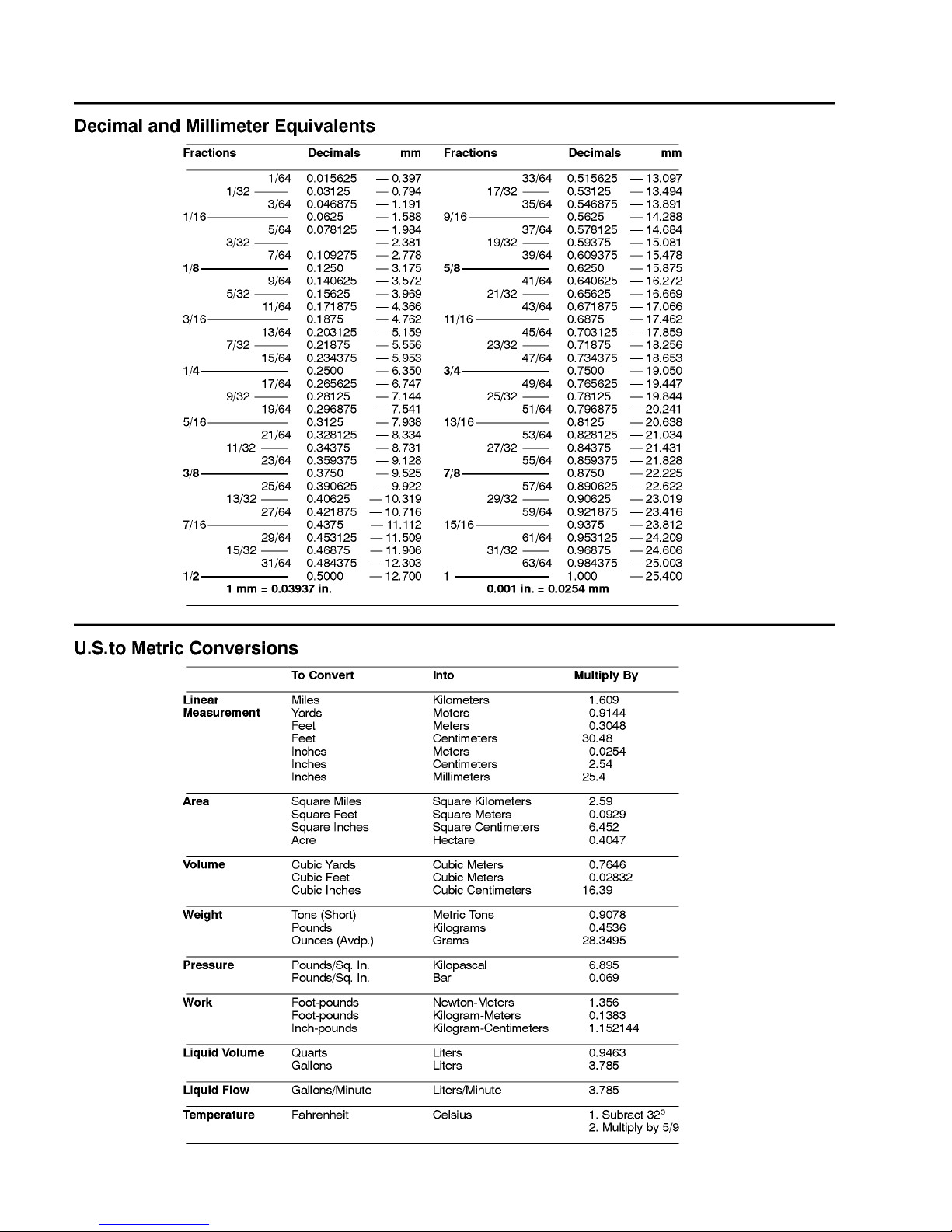
EQUIVALENTS AND CONVERSIONS 2. . . . . . . . . . .
Decimal and Millimeter Equivalents 2. . . . . . . . . . . .
U.S. to Metric Conversions 2. . . . . . . . . . . . . . . . . . .
TORQUE SPECIFICATIONS 3. . . . . . . . . . . . . . . . . . .
Fastener Identification 3. . . . . . . . . . . . . . . . . . . . . . .
Standard Torque for Dry, Zinc Plated, and Steel
Fasteners (Inch Series Fasteners) 4. . . . . . . . . . .
Standard Torque for Dry, Zinc Plated, and Steel
Fasteners (Metric Fasteners) 5. . . . . . . . . . . . . . .
Other Torque Specifications 6. . . . . . . . . . . . . . . . . .
Conversion Factors 6. . . . . . . . . . . . . . . . . . . . . . . . .
Product Records
Insert Operator’s Manual and Parts Catalog for your
Greensmaster Flex 18 or Flex 21 at the end of this section. Additionally, if any optional equipment or accessories have been installed to your machine, insert the
Installation Instructions, Operator’s Manuals and Parts
Catalogs for those options at the end of this chapter.
Maintenance
Maintenance procedures and recommended service intervals for the Greensmaster Flex 18 and Flex 21 are
covered in the Operator’s Manual. Refer to that publication when performing regular equipment maintenance.
Product Records
and Maintenance
0.09375
Greensmaster Flex 18/21Page 2 – 2Product Records and Maintenance
Equivalents and Conversions
Greensmaster Flex 18/21 Page 2 – 3 Product Records and Maintenance
Torque Specifications
Recommended fastener torque values are listed in the
following tables. For critical applications, as determined
by Toro, either the recommended torque or a torque that
is unique to the application is clearly identified and specified in this Service Manual.
These Torque Specifications for the installation and
tightening of fasteners shall apply to all fasteners which
do not have a specific requirement identified in this Service Manual. The following factors shall be considered
when applying torque: cleanliness of the fastener, use
of a thread sealant (e.g. Loctite), degree of lubrication
on the fastener, presence of a prevailing torque feature
(e.g. Nylock nut), hardness of the surface underneath
the fastener’s head or similar condition which affects the
installation.
As noted in the following tables, torque values should be
reduced by 25% for lubricated fasteners to achieve
the similar stress as a dry fastener. Torque values may
also have to be reduced when the fastener is threaded
into aluminum or brass. The specific torque value
should be determined based on the aluminum or brass
material strength, fastener size, length of thread engagement, etc.
The standard method of verifying torque shall be performed by marking a line on the fastener (head or nut)
and mating part, then back off fastener 1/4 of a turn.
Measure the torque required to tighten the fastener until
the lines match up.
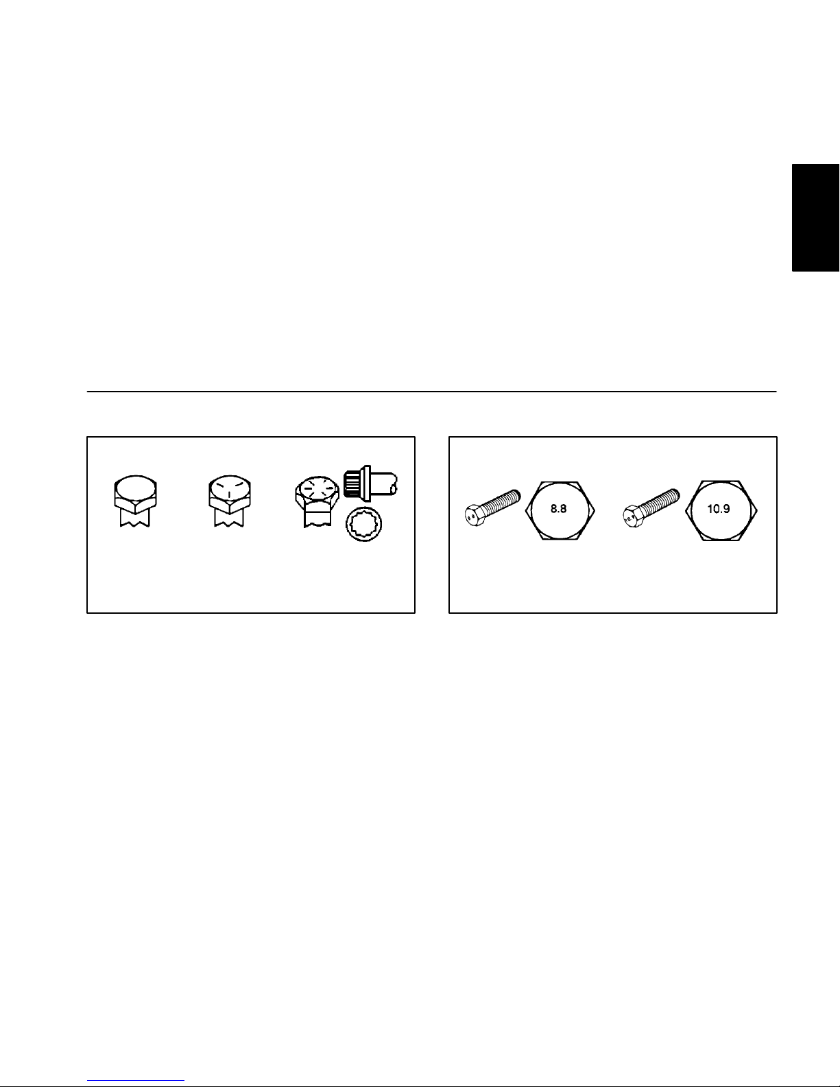
Fastener Identification
Grade 1 Grade 5 Grade 8
Inch Series Bolts and Screws
Class 8.8 Class 10.9
Metric Bolts and Screws
Product Records
and Maintenance

Greensmaster Flex 18/21Page 2 – 4Product Records and Maintenance
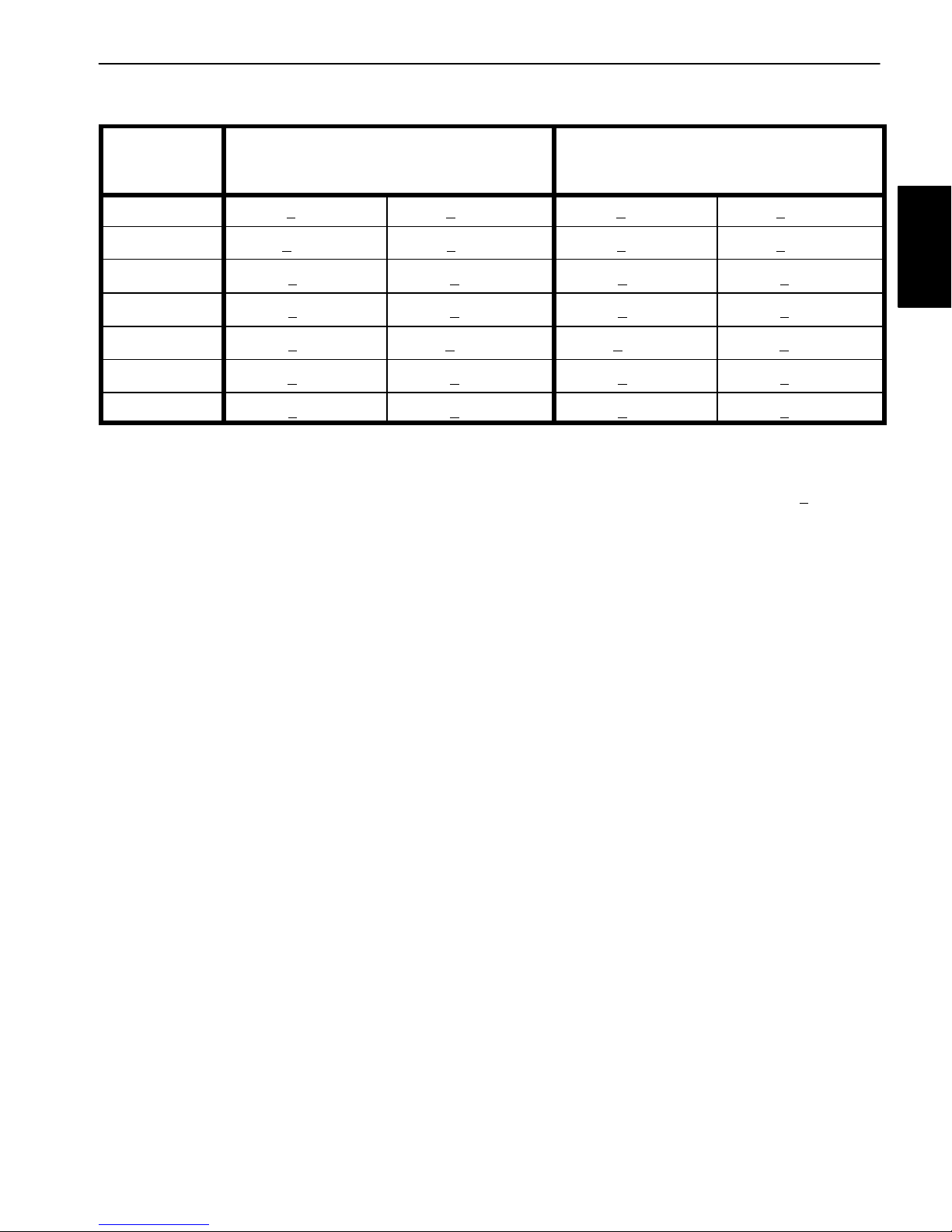
Standard Torque for Dry, Zinc Plated and Steel Fasteners (Inch Series Fasteners)
Thread Size
Grade 1, 5 &
8 with Thin
Height Nuts
SAE Grade 1 Bolts, Screws, Studs &
Sems with Regular Height Nuts
(SAE J995 Grade 2 or Stronger Nuts)
SAE Grade 5 Bolts, Screws, Studs &
Sems with Regular Height Nuts
(SAE J995 Grade 2 or Stronger Nuts)
SAE Grade 8 Bolts, Screws, Studs &
Sems with Regular Height Nuts
(SAE J995 Grade 5 or Stronger Nuts)
in–lb in–lb N–cm in–lb N–cm in–lb N–cm
# 6 – 32 UNC
15 + 2 169 + 23 23 + 3 262 + 34
# 6 – 40 UNF
10 + 2 13 + 2 147 + 23
17 + 2 192 + 23 25 + 3 282 + 34
# 8 – 32 UNC
29 + 3 328 + 34 41 + 5 463 + 56
# 8 – 36 UNF
13 + 2 25 + 5 282 + 56
31 + 4 350 + 45 43 + 5 486 + 56
# 10 – 24 UNC
42 + 5 475 + 56 60 + 6 678 + 68
# 10 – 32 UNF
18 + 2 30 + 5 339 + 56
48 + 5 542 + 56 68 + 7 768 + 79
1/4 – 20 UNC 48 + 7 53 + 7 599 + 79 100 + 10 1130 + 113 140 + 15 1582 + 169
1/4 – 28 UNF 53 + 7 65 + 10 734 + 113 115 + 12 1299 + 136 160 + 17 1808 + 192
5/16 – 18 UNC 115 + 15 105 + 15 1186 + 169 200 + 25 2260 + 282 300 + 30 3390 + 339
5/16 – 24 UNF 138 + 17 128 + 17 1446 + 192 225 + 25 2542 + 282 325 + 33 3672 + 373
ft–lb ft–lb N–m ft–lb N–m ft–lb N–m
3/8 – 16 UNC 16 + 2 16 + 2 22 + 3 30 + 3 41 + 4 43 + 5 58 + 7
3/8 – 24 UNF 17 + 2 18 + 2 24 + 3 35 + 4 47 + 5 50 + 6 68 + 8
7/16 – 14 UNC 27 + 3 27 + 3 37 + 4 50 + 5 68 + 7 70 + 7 95 + 9
7/16 – 20 UNF 29 + 3 29 + 3 39 + 4 55 + 6 75 + 8 77 + 8 104 + 11
1/2 – 13 UNC 30 + 3 48 + 7 65 + 9 75 + 8 102 + 11 105 + 11 142 + 15
1/2 – 20 UNF 32 + 4 53 + 7 72 + 9 85 + 9 115 + 12 120 + 12 163 + 16
5/8 – 11 UNC 65 + 10 88 + 12 119 + 16 150 + 15 203 + 20 210 + 21 285 + 28
5/8 – 18 UNF 75 + 10 95 + 15 129 + 20 170 + 18 230 + 24 240 + 24 325 + 33
3/4 – 10 UNC 93 + 12 140 + 20 190 + 27 265 + 27 359 + 37 375 + 38 508 + 52
3/4 – 16 UNF 115 + 15 165 + 25 224 + 34 300 + 30 407 + 41 420 + 43 569 + 58
7/8 – 9 UNC 140 + 20 225 + 25 305 + 34 430 + 45 583 + 61 600 + 60 813 + 81
7/8 – 14 UNF 155 + 25 260 + 30 353 + 41 475 + 48 644 + 65 667 + 66 904 + 89
NOTE: Torque values may have to be reduced when
installing fasteners into threaded aluminum or brass.
The specific torque value should be determined based
on the fastener size, the aluminum or base material
strength, length of thread engagement, etc.
NOTE: Reduce torque values listed in the table above
by 25% for lubricated fasteners. Lubricated fasteners
are defined as threads coated with a lubricant such as
engine oil or thread sealant such as Loctite.
NOTE: The nominal torque values listed above for
Grade 5 and 8 fasteners are based on 75% of the minimum proof load specified in SAE J429. The tolerance is
approximately +
10% of the nominal torque value. Thin
height nuts include jam nuts.
Greensmaster Flex 18/21 Page 2 – 5 Product Records and Maintenance
Standard Torque for Dry, Zinc Plated and Steel Fasteners (Metric Fasteners)
Class 8.8 Bolts, Screws and Studs with
Class 10.9 Bolts, Screws and Studs with
Thread Size Regular Height Nuts
(Class 8 or Stronger Nuts)
Regular Height Nuts
(Class 10 or Stronger Nuts)
M5 X 0.8 57 + 6 in–lb 644 + 68 N–cm 78 + 8 in–lb 881 + 90 N–cm
M6 X 1.0 96 + 10 in–lb 1085 + 113 N–cm 133 + 14 in–lb 1503 + 158 N–cm
M8 X 1.25 19 + 2 ft–lb 26 + 3 N–m 28 + 3 ft–lb 38 + 4 N–m
M10 X 1.5 38 + 4 ft–lb 52 + 5 N–m 54 + 6 ft–lb 73 + 8 N–m
M12 X 1.75 66 + 7 ft–lb 90 + 10 N–m 93 + 10 ft–lb 126 + 14 N–m
M16 X 2.0 166 + 17 ft–lb 225 + 23 N–m 229 + 23 ft–lb 310 + 31 N–m
M20 X 2.5 325 + 33 ft–lb 440 + 45 N–m 450 + 46 ft–lb 610 + 62 N–m
NOTE: Torque values may have to be reduced when
installing fasteners into threaded aluminum or brass.
The specific torque value should be determined based
on the fastener size, the aluminum or base material
strength, length of thread engagement, etc.
NOTE: Reduce torque values listed in the table above
by 25% for lubricated fasteners. Lubricated fasteners
are defined as threads coated with a lubricant such as
engine oil or thread sealant such as Loctite.
NOTE: The nominal torque values listed above are
based on 75% of the minimum proof load specified in
SAE J1199. The tolerance is approximately +
10% of the
nominal torque value.
Product Records
and Maintenance
Greensmaster Flex 18/21Page 2 – 6Product Records and Maintenance
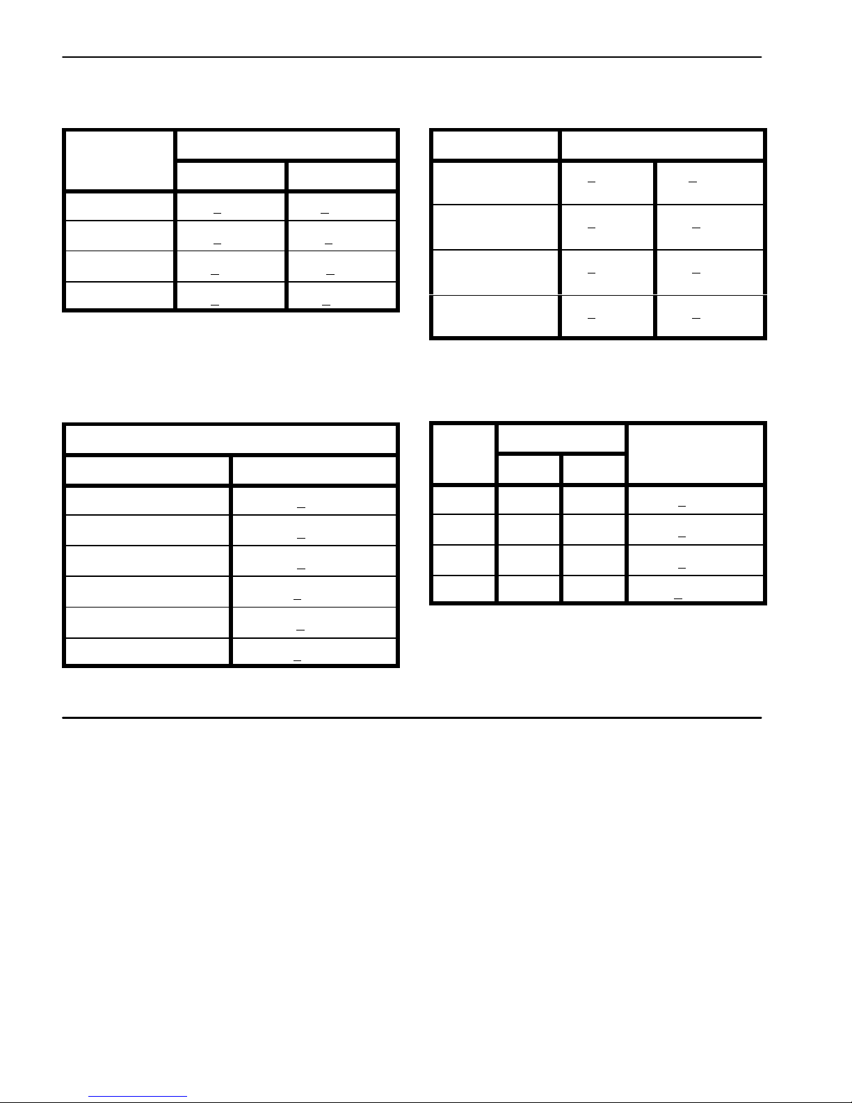
Other Torque Specifications
SAE Grade 8 Steel Set Screws
Recommended Torque
Thread Size
Square Head Hex Socket
1/4 – 20 UNC 140 + 20 in–lb 73 + 12 in–lb
5/16 – 18 UNC 215 + 35 in–lb 145 + 20 in–lb
3/8 – 16 UNC 35 + 10 ft–lb 18 + 3 ft–lb
1/2 – 13 UNC 75 + 15 ft–lb 50 + 10 ft–lb
Thread Cutting Screws
(Zinc Plated Steel)
Type 1, Type 23 or Type F
Thread Size Baseline Torque*
No. 6 – 32 UNC 20 + 5 in–lb
No. 8 – 32 UNC 30 + 5 in–lb
No. 10 – 24 UNC 38 + 7 in–lb
1/4 – 20 UNC 85 + 15 in–lb
5/16 – 18 UNC 110 + 20 in–lb
3/8 – 16 UNC 200 + 100 in–lb
Wheel Bolts and Lug Nuts
Thread Size
Recommended Torque**
7/16 – 20 UNF
Grade 5
65 + 10 ft–lb 88 + 14 N–m
1/2 – 20 UNF
Grade 5
80 + 10 ft–lb 108 + 14 N–m
M12 X 1.25
Class 8.8
80 + 10 ft–lb 108 + 14 N–m
M12 X 1.5
Class 8.8
80 + 10 ft–lb 108 + 14 N–m
** For steel wheels and non–lubricated fasteners.
Thread Cutting Screws
(Zinc Plated Steel)
Thread
Threads per Inch
Size
Type A Type B
Baseline Torque*
No. 6 18 20 20 + 5 in–lb
No. 8 15 18 30 + 5 in–lb
No. 10 12 16 38 + 7 in–lb
No. 12 11 14 85 + 15 in–lb
* Hole size, material strength, material thickness & finish
must be considered when determining specific torque
values. All torque values are based on non–lubricated
fasteners.
Conversion Factors
in–lb X 11.2985 = N–cm N–cm X 0.08851 = in–lb
ft–lb X 1.3558 = N–m N–m X 0.7376 = ft–lb

Greensmaster Flex 18/21 Page 3 – 1 Engine
Chapter 3
Engine
Table of Contents
SPECIFICATIONS 2. . . . . . . . . . . . . . . . . . . . . . . . . . . .
INTRODUCTION 3. . . . . . . . . . . . . . . . . . . . . . . . . . . . . .
GENERAL INFORMATION 3. . . . . . . . . . . . . . . . . . . . .
Operator’s Manual 3. . . . . . . . . . . . . . . . . . . . . . . . . .
ADJUSTMENTS 4. . . . . . . . . . . . . . . . . . . . . . . . . . . . . .
Throttle Cable Adjustment 4. . . . . . . . . . . . . . . . . . . .
SERVICE AND REPAIRS 5. . . . . . . . . . . . . . . . . . . . . .
Cooling System 5. . . . . . . . . . . . . . . . . . . . . . . . . . . . .
Ignition Components 5. . . . . . . . . . . . . . . . . . . . . . . .
Spark Plug 6. . . . . . . . . . . . . . . . . . . . . . . . . . . . . . . . .
Engine 8. . . . . . . . . . . . . . . . . . . . . . . . . . . . . . . . . . . . .
KAWASAKI FE120 SERVICE MANUAL
Engine

Greensmaster Flex 18/21Page 3 – 2Engine
Specifications
Item Description
Make / Designation Kawasaki, 4–stroke, OHV, single cylinder,
air–cooled, gasoline engine, FE120D
Bore x Stroke 2.36” x 1.73” (60 mm x 44 mm)
Total Displacement 7.6 in3 (124 cc)
Compression Ratio 8.4:1
Carburetor Float feed, fixed main jet
Governor Mechanical flyweight
Low Idle Speed (no load) 2400 + 100 RPM
High Idle Speed (no load) 3600 + 100 RPM
Direction of rotation Counter clockwise (facing PTO shaft)
Fuel Unleaded, automotive grade gasoline
Fuel Tank Capacity 2.6 U.S. qt (2.5 l)
Engine Oil See Operator’s Manual
Lubrication System Splash type
Oil Capacity 0.63 U.S. qt (0.6 l)
Air Cleaner Dual element
Ignition System Transistorized flywheel magneto with ignition advance
Spark Plug NGK BPR 5ES
Spark Plug Gap 0.028” to 0.032” (0.7 to 0.8 mm)
Dry Weight 32.4 lbs (14.7 kg)
Engine

Greensmaster Flex 18/21 Page 3 – 3 Engine
Introduction
This Chapter gives information about specifications,
maintenance, troubleshooting, testing and repair of the
gasoline engine used in the Greensmaster Flex 18 and
Flex 21 mowers.
Most repairs and adjustments require tools which are
commonly available in many service shops. Special
tools are described in the Kawasaki FE120D Service
Manual that is included at the end of this Chapter. The
use of some specialized test equipment is explained.
However, the cost of the test equipment and the specialized nature of some repairs may dictate that the work be
done at an engine repair facility.
Service and repair parts for Kawasaki engines are supplied through your local Toro distributor. Be prepared to
provide your distributor with the Toro model and serial
number.
General Information
Operator’s Manual
The Operator’s Manual provides information regarding
the operation, general maintenance and maintenance
intervals for your Greensmaster machine. Refer to the
Operator’s Manual for additional information when servicing the machine.
Greensmaster Flex 18/21Page 3 – 4Engine
Adjustments
Throttle Cable Adjustment
If a new throttle cable must be installed or the cable is
out of adjustment, adjust the cable as follows:
1. Park machine on a level surface. Make sure engine
is OFF. Remove spark plug wire from the spark plug.
2. Move throttle control lever on the handle to the F AST
position.
3. Loosen throttle cable screw that secures the throttle
cable to the governor lever.
4. Make sure throttle lever is in the FAST position and
the governor lever is against the high idle speed screw.
5. Tighten throttle cable screw to secure the throttle
cable to the governor lever.
6. After cable adjustment, connect spark plug wire to
spark plug, start engine and check engine speed with a
tachometer:
A. Low idle speed should be 2300 to 2500 RPM. Ad-
just low idle speed screw in or out to attain the correct
low idle speed setting.
B. High idle speed should be 3500 to 3700 RPM.
Adjust high idle speed screw in or out to attain the
correct high idle speed setting.
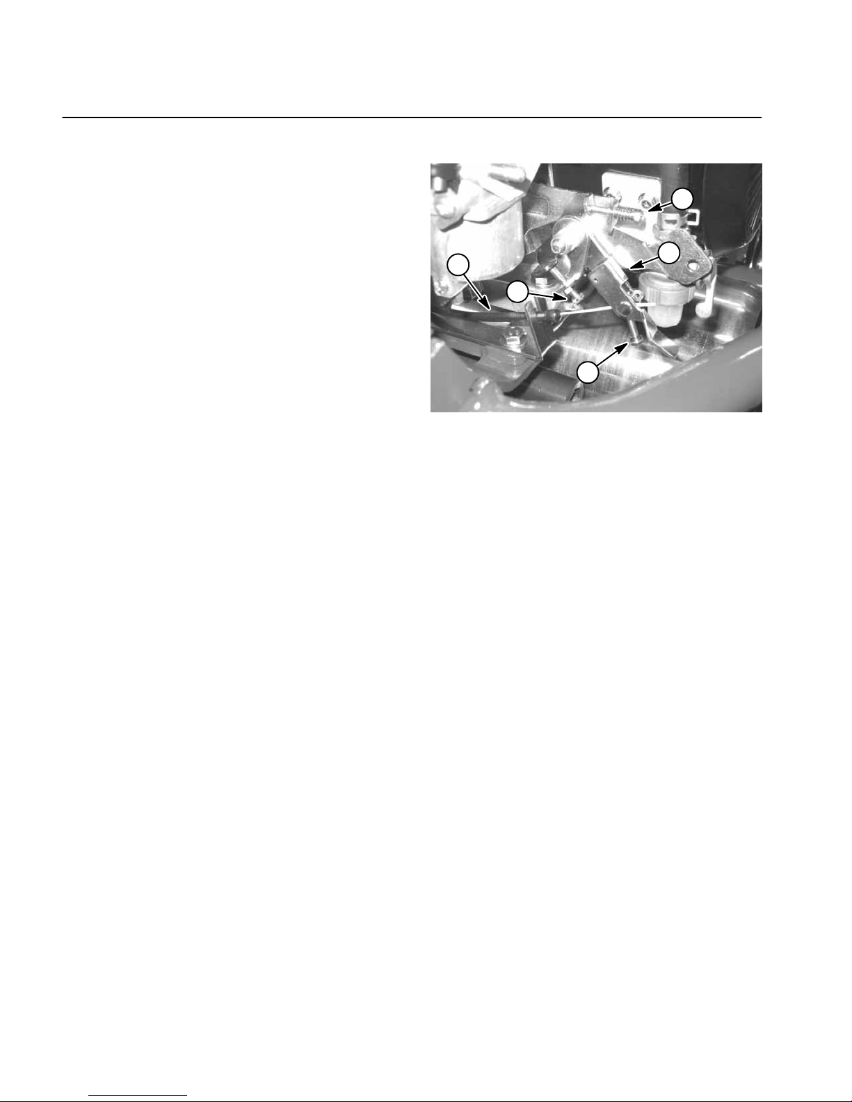
Figure 1
1. Throttle cable screw
2. Throttle cable
3. Governor lever
4. Low idle speed screw
5. High idle speed screw
3
2
4
1
5
Greensmaster Flex 18/21 Page 3 – 5 Engine
Service and Repairs
Cooling System
IMPORTANT: The engine that powers the Flex 18
and Flex 21 is air–cooled. Operating the engine with
dirty or plugged cooling fins or a plugged or dirty blower housing will result in engine overheating and
damage.
1. Park machine on a level surface. Make sure engine
is OFF. Remove spark plug wire from the spark plug.
IMPORTANT: Never clean engine with pressurized
water. Water could enter and contaminate the fuel
system.
2. Clean cooling fins on cylinder and cylinder head. Remove engine cylinder shroud from engine for more thorough cleaning (Fig. 2).
3. Clean blower housing of dirt and debris (Fig. 3). Remove housing if necessary.
IMPORTANT: Never operate engine without the
blower housing installed. Overheating and engine
damage will result.
4. Make sure blower housing and/or engine cylinder
shroud are installed to the engine if removed.
5. Attach spark plug wire to spark plug.
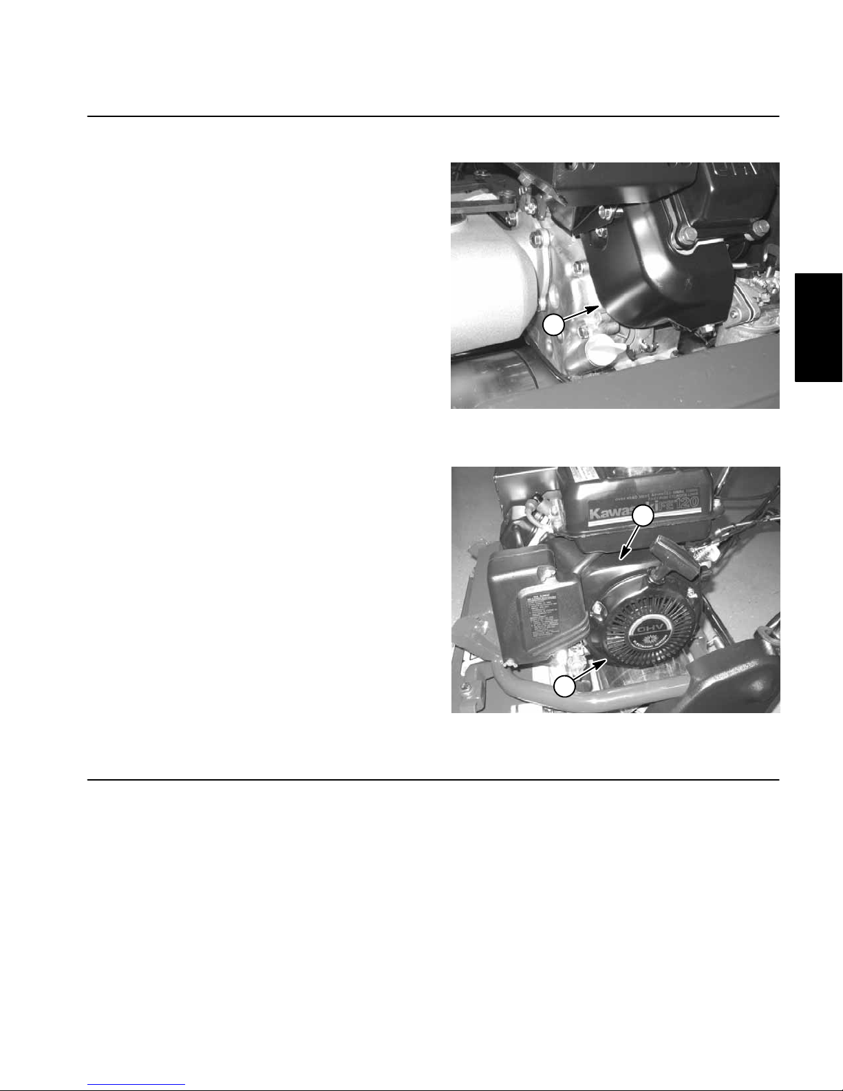
Figure 2
1. Engine cylinder shroud
1
Figure 3
1. Blower housing 2. Rewind starter
1
2
Ignition Components
Engine ignition component information is included in
Chapter 5 – Electrical System.
Engine
Greensmaster Flex 18/21Page 3 – 6Engine
Spark Plug
Use a NGK BPR 5ES spark plug or equivalent.
1. Make sure engine is OFF. Carefully pull spark plug
wire off the spark plug.
2. Clean around spark plug and remove plug from the
cylinder head.
NOTE: The condition of the spark plug can give an accurate picture of the overall condition of the engine. Use
the chart on the following page as a guide to determine
possible problems with the engine.
3. Inspect the spark plug.
IMPORTANT: Replace a cracked, fouled or dirty
spark plug. Do not sand blast, scrape or clean spark
plug electrodes because engine damage could result from grit entering cylinder.
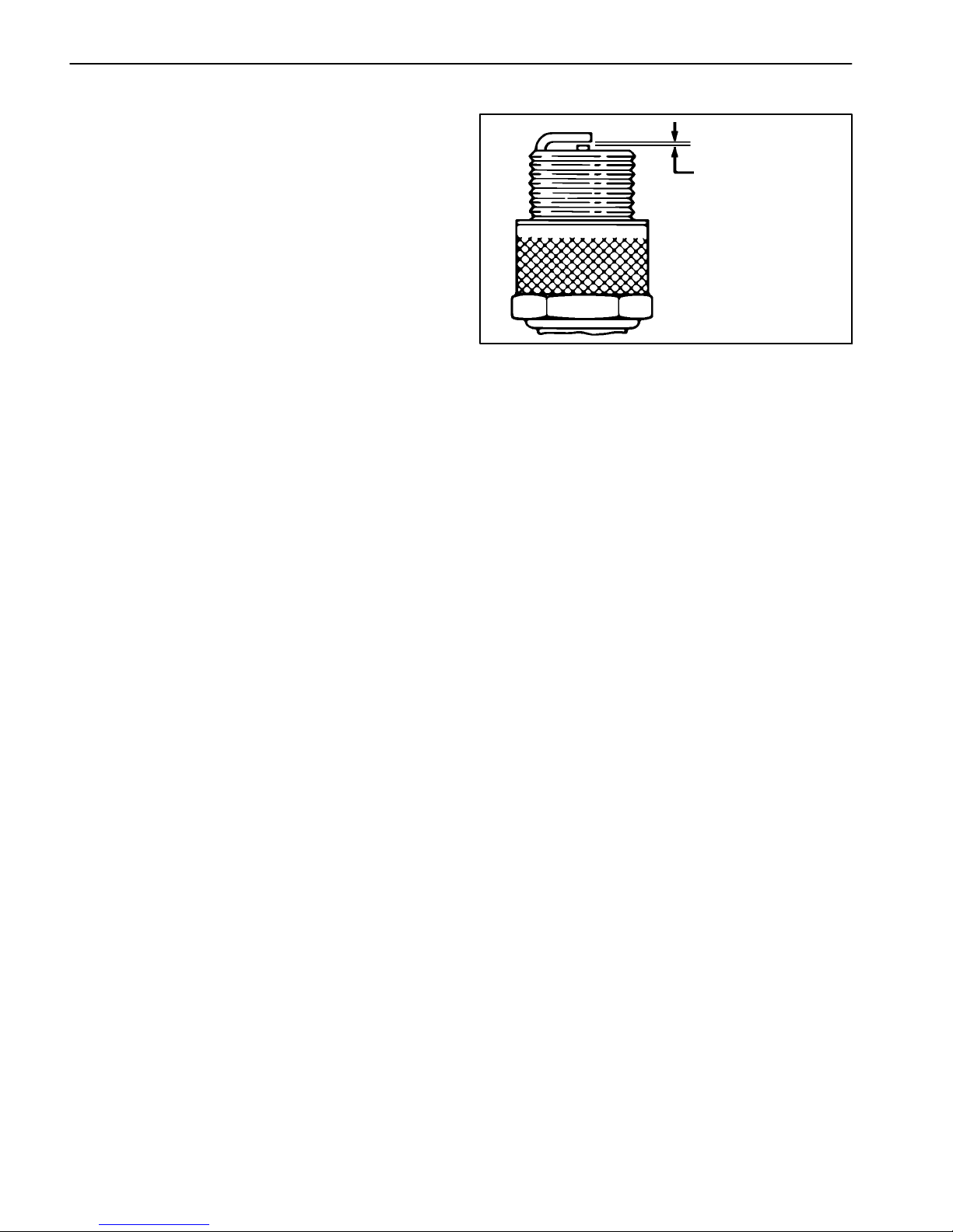
4. Set electrode gap from 0.028” to 0.032” (0.7 to 0.8
mm). Install correctly gapped spark plug into cylinder
head and torque plug to 17 ft–lb (23 N–m). Connect
spark plug wire to spark plug.
Figure 4
0.028” to 0.032“
(0.7 to 0.8 mm)

Greensmaster Flex 18/21 Page 3 – 7 Engine
OIL FOULED PRE–IGNITION
WORN
NORMAL
LEAD FOULED CARBON FOULED
OVER HEATING FUSED SPOT DEPOSIT
GAP BRIDGED
Black dry fluffy carbon deposits are found
on insulator tip, electrodes and exposed
shell surfaces.
Weak ignition, plug heat range too cold, fuel
mixture too rich or excessive idling may be
the cause.
Replace spark plug.
Has dark black, gray, tan or yellow deposits.
May have a fused glazed coating on the insulator tip.
Caused by highly leaded gasoline.
Replace spark plug.
Gap between electrodes is closed by deposit build up.
May be caused by carbon or oil fouling.
Replace spark plug.
Wet black deposits can be found on electrodes, insulator and in the bore.
Excessive oil entering the combustion
chamber past worn valve guides, valve
stems, rings, piston and/or cylinder bore.
Replace spark plug.
Has gray or light tan deposits on the firing
tip.
Light gray or white insulator with small gray
brown or black spots. Electrode has a bluish
burnt appearance.
May be caused by engine overheating,
loose spark plug, wrong fuel type, plug heat
range too hot or incorrect ignition timing.
Replace spark plug.
Has spotty or melted deposits resembling
blisters or bubbles.
Replace spark plug.
Has severely eroded or worn electrodes.
Caused by normal wear.
Replace spark plug.
Electrodes are melted and the insulator
may be blistered. Metallic deposits on the
insulator indicate engine damage.
Engine overheating, burnt valves, plug heat
range too hot, incorrect ignition timing or
wrong type of fuel are causes.
Replace spark plug.
Engine

Greensmaster Flex 18/21Page 3 – 8Engine
Engine
Figure 5
1. Gearbox assembly
2. Flange gasket
3. Engine gear
4. Engine adapter
5. Engine
6. Flat washer (4 used)
7. Flange nut (8 used)
8. Cap screw (4 used)
9. Hourmeter bracket
10. Damper
11. Cap screw (3 used)
12. Wire harness
13. Interlock module
14. Module bracket
15. Throttle cable screw
16. Set screw (4 used)
17. Cap screw
18. Lock washer (2 used)
19. Flat washer
20. Flat washer
21. Lock nut
22. Cap screw
23. Isolator mount (2 used)
24. Jam nut (2 used)
25. Tab washer (2 used)
26. Hourmeter
27. Lock washer (2 used)
28. Muffler guard
29. Cap screw (4 used)
30. Muffler guard bracket (2 used)
31. Square key
32. Washer head screw (4 used)
33. Flat washer (4 used)
34. Hourmeter mounting clip
FRONT
RIGHT
1
17
18
19
3
4
16
32
28
29
33
30
21
11
18
14
13
20
22
11
27
12
11
27
26
9
34
5
15
6
8
10
23
25
24
7
7
2
Loctite #242
7 to 10 in–lb
(0.8 to 1.1 N–m)
31
Greensmaster Flex 18/21 Page 3 – 9 Engine
Engine Removal (Fig. 5)
1. Make sure machine is parked on a level surface with
the engine OFF . Remove spark plug wire from the spark
plug to prevent the engine from starting. Close fuel
shut–off valve.
2. If engine is to be disassembled, it may be easier to
drain oil from engine before removing engine from traction unit.
3. Drain oil from gearbox.
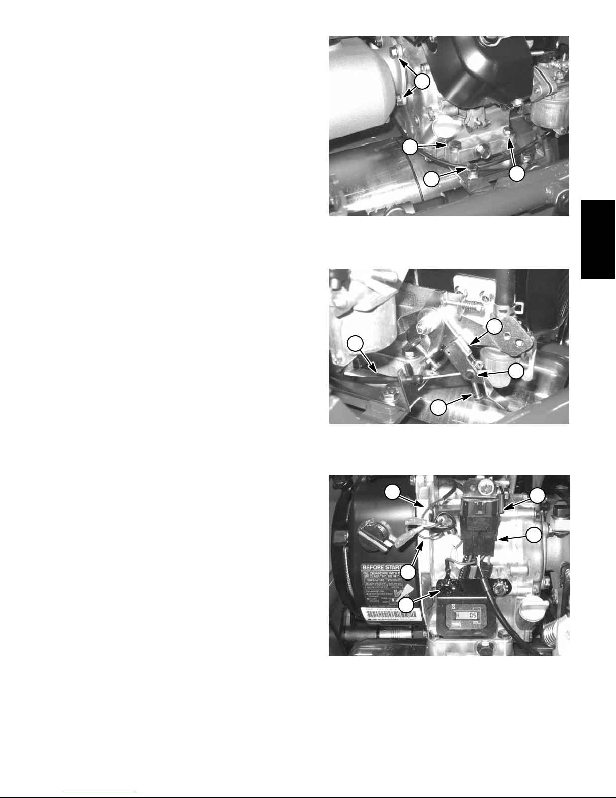
4. Remove throttle cable from engine:
A. Remove cap screw and flange nut that secure
cable clamp to traction unit frame (Fig. 6). Locate
and retrieve three (3) washers from under clamp.
B. Loosen screw that secures throttle cable to
throttle cable nut enough to slide the cable out of the
nut (Fig. 7).
C. Position throttle cable away from engine.
5. Disconnect electrical connections from engine (Fig.
8):
A. Unplug wire harness connector from interlock
module.
B. Disconnect engine stop switch and armature
wires from wire harness connectors.
C. Disconnect wire harness ground wire from en-
gine by removing cap screw and lock washer.
6. Remove engine from the engine base (Fig. 6):
A. Remove four (4) flange nuts that secure gearbox
assembly to set screws on engine crankcase cover.
B. Support gearbox between mower frame and
gearbox flange.
C. Remove four (4) cap screws, flat washers and
flange nuts that secure engine to engine base of traction unit.
D. Carefully slide engine away from gearbox assembly to allow engine gear to clear gearbox. Remove and discard flange gasket (item 2).
E. Remove the engine from the traction unit.
7. If necessary, remove cap screw, lock washer and flat
washer that secure engine gear to crankshaft. Slide
gear from crankshaft. Remove square key from engine
crankshaft keyway.
Figure 6
1. Gearbox flange nuts
2. Engine mounting screws
3. Throttle cable clamp
2
1
2
3
Figure 7
1. Governor lever
2. Throttle cable
3. Throttle cable screw
4. Throttle cable nut
1
2
4
3
Figure 8
1. Wire harness
2. Interlock module
3. Stop switch wire
4. Armature wire
5. Cap screw/lock washer
1
5
2
4
3
Engine

Greensmaster Flex 18/21Page 3 – 10Engine
Engine Installation (Fig. 5)
1. Position machine on a level surface. Make sure that
spark plug wire is not connected to engine spark plug.
2. Make sure that all parts removed from the engine
during maintenance or rebuilding are properly installed
to the engine.
3. If engine gear was removed from crankshaft, position square key in crankshaft keyway. Slide gear onto
crankshaft. Secure gear to crankshaft with cap screw,
lock washer and flat washer.
4. Install engine to engine base (Fig. 5 and 6):
A. Make sure that four (4) set screws are secure in
engine crankcase cover. If set screws were removed
from engine cover , apply Loctite #242 (or equivalent)
to set screw threads, install into engine cover and
tighten securely.
B. Install new flange gasket (item 2) to set screws on
crankcase cover.
C. Position engine on the engine base with the drive
gear towards the gearbox assembly.
D. Slide engine toward gearbox while guiding drive
gear into gearbox input area. Crankshaft may have
to be turned to mesh engine gear teeth with gearbox
input gears.
E. Install and finger tighten four (4) flange nuts that
secure gearbox assembly to set screws on engine
crankcase cover.
F. Install four (4) cap screws with flat washers
through the engine and engine base. Put flange nut
on each cap screw and hand tighten.
G. Fully tighten flange nuts that secure gearbox assembly to engine and then tighten flange nuts that
secure engine to engine base.
5. Connect electrical connections to engine (Fig. 8):
A. Connect wire harness connectors to engine stop
switch and armature wires.
B. Secure ground wire to engine with cap screw and
lock washer.
C. Connect wire harness to interlock module.
6. Connect throttle cable to engine.
A. Position throttle cable to engine.
B. Slide throttle cable through throttle cable nut (Fig.
7).
C. Position three (3) washers and cable clamp to
frame (Fig. 6). Secure with cap screw and flange nut.
D. Adjust throttle cable (See Throttle Cable Adjust-
ment in the Adjustment section of this chapter).
Make sure that throttle cable screw is tightened after
cable adjustment.
7. Fill gearbox to proper fluid level.
8. Check and adjust engine oil level as needed.
9. Attach spark plug wire to the spark plug. Open fuel
shut–off valve.

Greensmaster Flex 18/21 Traction and Reel Drive SystemPage 4 – 1
Chapter 4
Traction and Reel Drive System
Table of Contents
SPECIFICATIONS 2. . . . . . . . . . . . . . . . . . . . . . . . . . . .
GENERAL INFORMATION 3. . . . . . . . . . . . . . . . . . . . .
Operator’s Manual 3. . . . . . . . . . . . . . . . . . . . . . . . . .
Gearbox Seals 3. . . . . . . . . . . . . . . . . . . . . . . . . . . . . .
SERVICE AND REPAIRS 5. . . . . . . . . . . . . . . . . . . . . .
Reel Drive and Transmission Coupler
Drive Belt Replacement 5. . . . . . . . . . . . . . . . . . . .
Reel Drive Assembly 6. . . . . . . . . . . . . . . . . . . . . . . .
Reel Drive and Transmission Coupler
Bearing Housing 7. . . . . . . . . . . . . . . . . . . . . . . . . .
Traction Drive Belt Replacement 10. . . . . . . . . . . . .
Traction Drive Idler Pulley and Bearings 11. . . . . . . .
Traction Drum Assembly 12. . . . . . . . . . . . . . . . . . . .
Gearbox 16. . . . . . . . . . . . . . . . . . . . . . . . . . . . . . . . . .
Gearbox Service 18. . . . . . . . . . . . . . . . . . . . . . . . . . .
Differential Service 22. . . . . . . . . . . . . . . . . . . . . . . . .
Traction and Reel
Drive System

Greensmaster Flex 18/21Traction and Reel Drive System Page 4 – 2
Specifications
Item Description
Traction Drive Integral Gearbox Assembly Attached Directly to Engine
Differential to Traction Drive has 8 mm Pitch Positive Drive Belts
Gearbox Fluid Dexron III Automatic Transmission Fluid (or equivalent)
Gearbox Fluid Capacity 2.9 U.S. qt (2.8 l)
Differential Integral in Gearbox Assembly
Parking Brake Band Drum (in gearbox)
Traction Drum Dual Cast Aluminum, 7.5 inch (19.1 cm) Diameter
Cutting Reel Drive Gear Driven Countershaft (in gearbox) with Cone Wet Clutch
Flexible Coupler Shaft Used in Reel Drive System
Gearbox to Reel Drive has 8 mm Pitch Positive Drive Belts

Greensmaster Flex 18/21 Traction and Reel Drive SystemPage 4 – 3
General Information
Operator’s Manual
The Operator’s Manual provides information regarding
the operation, general maintenance and maintenance
intervals for your Greensmaster machine. Refer to the
Operator’s Manual for additional information when servicing the machine.
Gearbox Seals
The Greensmaster Flex 18 and Flex 21 use cannister
seals in the gearbox. This type of seal is internally lubricated and, like other seals, could normally have a light
lubricant film evident at the seal lips. Cannister seals will
also cause a slightly higher amount of drag than other
seal types.
Traction and Reel
Drive System

Greensmaster Flex 18/21Traction and Reel Drive System Page 4 – 4
This page is intentionally blank.

Greensmaster Flex 18/21 Traction and Reel Drive SystemPage 4 – 5
Service and Repairs
Reel Drive and Transmission Coupler Drive Belt Replacement (Fig. 1 and 2)
Flex 18 and Flex 21 machines use two identical positive
drive belts to operate the cutting unit. Replacement of
these belts requires the same procedure.
Removal
1. Park machine on a level surface. Make sure engine
is OFF. Remove spark plug wire from the engine spark
plug.
2. Remove belt cover to expose appropriate drive belt:
right side (Fig. 1) or left side (Fig. 2).
3. Loosen the two (2) bearing housing mounting nuts.
4. Pivot bearing housing to loosen belt tension. Remove drive belt from the two pulleys.
Installation
1. Park machine on a level surface. Make sure engine
is OFF. Remove spark plug wire from the spark plug.
2. Place a new drive belt onto the two pulleys.
3. Adjust drive belt tension (see Operator’s Manual).
4. Install belt cover to machine and secure with flange
nut. Torque flange nut 100 in–lb (11.3 N–m).
5. Connect spark plug wire to spark plug.
1. RH reel drive belt
2. Bearing housing nuts
3. Gearbox assembly
Figure 1
2
1
2
3
1. LH reel drive belt
2. Bearing housing nuts
3. LH cutting reel sideplate
Figure 2
2
1
2
3
Traction and Reel
Drive System
Greensmaster Flex 18/21Traction and Reel Drive System Page 4 – 6
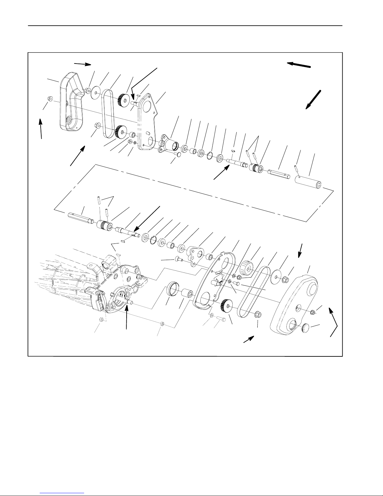
Reel Drive Assembly
1. Hex shaft
2. Flex coupling
3. Spring pin
4. Shaft
5. Oil seal
6. Retaining ring
7. Bearing
8. Spacer
9. Carriage screw (2 used per housing)
10. Bearing housing
11. Spacer
12. Flange nut (2 used per housing)
13. Flat washer (2 used per housing)
14. Woodruff key
15. Pulley (22 tooth)
16. Belt
17. Flange nut
18. Pulley washer
19. Belt cover assembly
20. Cap screw (2 used)
21. Spacer (2 used)
22. Lock nut (2 used)
23. Hex tube
24. Drive shaft plate assembly
25. Gearbox shaft
26. Reel drive plate assembly
27. Reel drive cover
28. Plug
29. Spacer
30. Spacer
31. Lock washer
32. Cap screw
33. Pulley (27 tooth)
Figure 3
3
1
2
3
4
5
6
7
8
7
10
11
15
16
17
15
12
9
13
FRONT
RIGHT
Antiseize Lubricant
100 in–lb
(11.3 N–m)
1
3
2
4
5
6
7
8
7
10
11
33
13
16
9
15
17
17
17
18
18
12
12
12
14
14
14
19
20
21
22
23
25
24
26
27
28
29
30
31
32
40 to 50 ft–lb
(54 to 68 N–m)
40 to 50 ft–lb
(54 to 68 N–m)
40 to 50 ft–lb
(54 to 68 N–m)
40 to 50 ft–lb
(54 to 68 N–m)
Antiseize Lubricant
Antiseize Lubricant
Antiseize
100 in–lb
(11.3 N–m)
Lubricant
13
NOTE: On early production Flex 18 cutting units, the 22
tooth pulley attached to the cutting reel (left side of cutting unit) is mounted with the flange toward the cutting
unit and has a pulley washer on the outside. These machines do not use a pulley washer (item 18) on the 27
tooth pulley (item 33).
 Loading...