

Page 1

Form No. 3327–369 Rev. A
Greensmaster Flex 21
Greensmaster Walk-Behind Mower
Model No. 04021—210000001 and Up (Traction Unit)
Model No. 04200—210000001 and Up (Cutting Unit)
Operator ’s Manual
Domestic English (EN)
Page 2

Warning
The engine exhaust from this product contains
chemicals known to the State of California to
cause cancer, birth defects, or other reproductive
harm.
This spark ignition system complies with Canadian
ICES-002.
Ce système d’allumage par étincelle de véhicule est
conforme à la norme NMB-002 du Canada.
Contents
Introduction 3. . . . . . . . . . . . . . . . . . . . . . . . . . . . . . . .
Safety 4. . . . . . . . . . . . . . . . . . . . . . . . . . . . . . . . . . . . .
Safe Operating Practices 4. . . . . . . . . . . . . . . . . . .
Toro Mower Safety 6. . . . . . . . . . . . . . . . . . . . . . .
Sound Pressure Level 7. . . . . . . . . . . . . . . . . . . . . .
Sound Power Level 7. . . . . . . . . . . . . . . . . . . . . . .
Vibration Level 7. . . . . . . . . . . . . . . . . . . . . . . . . .
Safety and Instruction Decals 7. . . . . . . . . . . . . . .
Specifications 9. . . . . . . . . . . . . . . . . . . . . . . . . . . . . . .
General Specifications 9. . . . . . . . . . . . . . . . . . . .
Dimensions 10. . . . . . . . . . . . . . . . . . . . . . . . . . . . . .
Optional Equipment 10. . . . . . . . . . . . . . . . . . . . . . .
Setup 11. . . . . . . . . . . . . . . . . . . . . . . . . . . . . . . . . . . . .
Loose Parts Chart 11. . . . . . . . . . . . . . . . . . . . . . . . .
Installing the Handle 11. . . . . . . . . . . . . . . . . . . . . .
Adjusting the Handle 12. . . . . . . . . . . . . . . . . . . . . .
Installing the Transport Wheels 12. . . . . . . . . . . . . .
Before Operating 13. . . . . . . . . . . . . . . . . . . . . . . . . . . .
Adding Engine Oil 13. . . . . . . . . . . . . . . . . . . . . . . .
Filling the Fuel Tank 13. . . . . . . . . . . . . . . . . . . . . .
Checking the Transmission Fluid 14. . . . . . . . . . . .
Separating Cutting Unit from Traction Unit 14. . . .
Leveling the Rear Roller to the Reel 15. . . . . . . . . .
Adjusting the Bedknife to the Reel 16. . . . . . . . . . .
Adjusting the Height of Cut 16. . . . . . . . . . . . . . . . .
Adjusting the Cut-Off Bar 17. . . . . . . . . . . . . . . . . .
Installing the Grass Basket 17. . . . . . . . . . . . . . . . .
Checking the Interlock Switch Operation 18. . . . . .
Page
Page
Operation 18. . . . . . . . . . . . . . . . . . . . . . . . . . . . . . . . . .
Think Safety First 18. . . . . . . . . . . . . . . . . . . . . . . .
Controls 18. . . . . . . . . . . . . . . . . . . . . . . . . . . . . . . .
Starting and Stopping 19. . . . . . . . . . . . . . . . . . . . . .
Transport Operation 20. . . . . . . . . . . . . . . . . . . . . . .
Preparing to Mow 20. . . . . . . . . . . . . . . . . . . . . . . . .
Mowing Operation 20. . . . . . . . . . . . . . . . . . . . . . . .
Maintenance 22. . . . . . . . . . . . . . . . . . . . . . . . . . . . . . . .
Recommended Maintenance Schedule 22. . . . . . . .
Daily Maintenance Checklist 23. . . . . . . . . . . . . . . .
Engine Oil 24. . . . . . . . . . . . . . . . . . . . . . . . . . . . . .
Servicing the Air Cleaner 24. . . . . . . . . . . . . . . . . .
Replacing the Spark Plug 25. . . . . . . . . . . . . . . . . . .
Cleaning the Fuel Filter 25. . . . . . . . . . . . . . . . . . . .
Changing the Transmission Fluid 25. . . . . . . . . . . .
Adjusting the Belts 26. . . . . . . . . . . . . . . . . . . . . . . .
Adjusting the Traction Control 29. . . . . . . . . . . . . .
Adjusting the Service/Parking Brake 29. . . . . . . . . .
Adjusting the Reel Control 29. . . . . . . . . . . . . . . . .
Servicing the Interlock Switch 30. . . . . . . . . . . . . . .
Servicing the Bedbar 30. . . . . . . . . . . . . . . . . . . . . .
Backlapping the Reel 31. . . . . . . . . . . . . . . . . . . . . .
The Toro General Commercial Products Warranty 32. .
2000 by The Toro Company
8111 Lyndale Avenue South
Bloomington, MN 55420-1196
All Rights Reserved
Printed in the USA
2
Page 3
Introduction
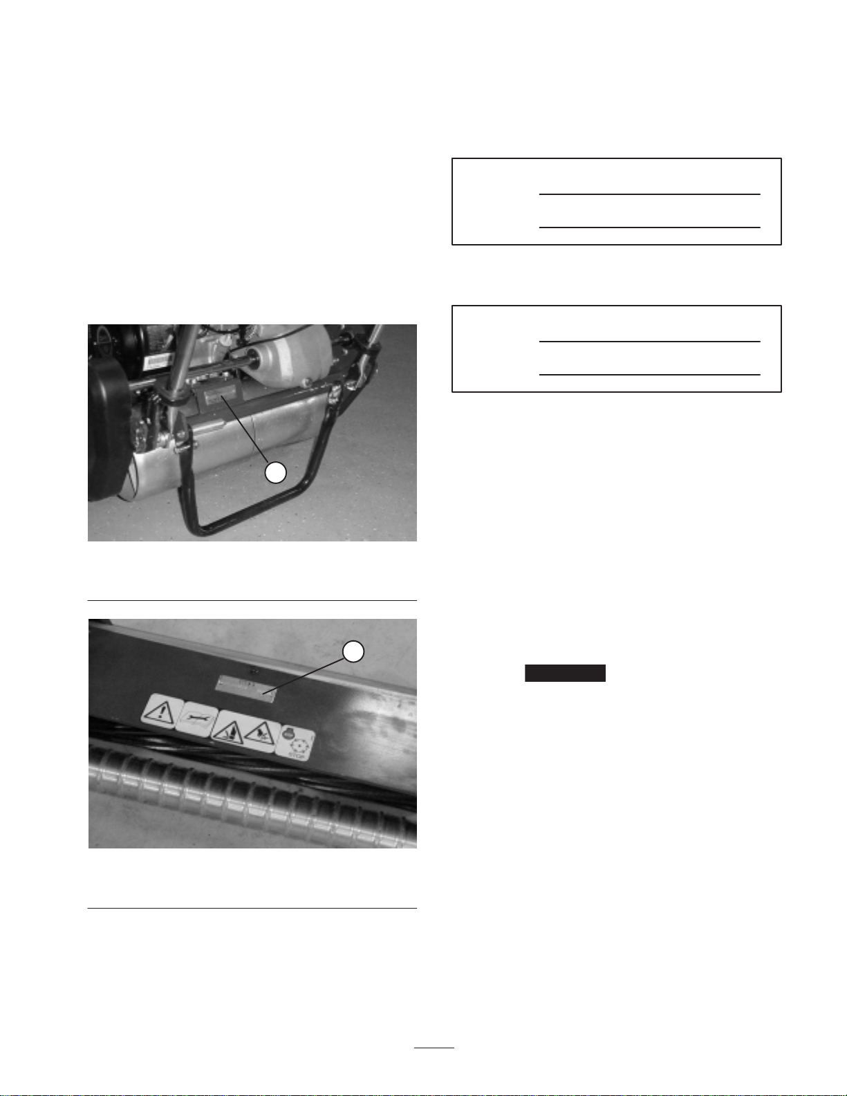
Write the product model and serial numbers in the space
below:
Read this manual carefully to learn how to operate and
maintain your product properly. The information in this
manual can help you and others avoid injury and product
damage. Although Toro designs and produces safe
products, you are responsible for operating the product
properly and safely.
Whenever you need service, genuine Toro parts, or
additional information, contact an Authorized Service
Dealer or Toro Customer Service and have the model and
serial numbers of your product ready. Figures 1 & 2
illustrate the location of the model and serial numbers on
the product.
1
Traction unit
Model No.
Serial No.
Cutting unit
Model No.
Serial No.
This manual identifies potential hazards and has special
safety messages that help you and others avoid personal
injury and even death. Danger, Warning, and Caution are
signal words used to identify the level of hazard.
However, regardless of the hazard, be extremely careful.
Danger signals an extreme hazard that will cause serious
injury or death if you do not follow the recommended
precautions.
Figure 1
1. Location o f the model and serial numbers–Traction unit
1
Figure 2
1. Location o f the model and serial numbers–Cutting unit
Warning signals a hazard that may cause serious injury or
death if you do not follow the recommended precautions.
Caution signals a hazard that may cause minor or
moderate injury if you do not follow the recommended
precautions.
This manual uses two other words to highlight
information. Important calls attention to special
mechanical information and Note: emphasizes general
information worthy of special attention.
3
Page 4

Safety
– Refuel outdoors only and do not smoke while
refuelling.
This machine meets or exceeds CEN standard EN
836:1997, ISO standard 5395:1990, and ANSI
B71.4-1999 specifications in effect at the time of
production when the Operator Presence Kit, Part No.
105–5333 is installed.
Improper use or maintenance by the operator or owner
can result in injury. To reduce the potential for injury,
comply with these safety instructions and always pay
attention to the safety alert symbol, which means
CAUTION, WARNING, or DANGER—“personal
safety instruction.” Failure to comply with the
instruction may result in personal injury or death.
Safe Operating Practices
The following instructions are from the CEN standard EN
836:1997, ISO standard 5395:1990, and ANSI
B71.4-1999.
Training
• Read the Operator ’s Manual and other training
material carefully. Be familiar with the controls, safety
signs, and the proper use of the equipment.
• Never allow children or people unfamiliar with these
instructions to use or service the mower. Local
regulations may restrict the age of the operator.
• Never mow while people, especially children, or pets
are nearby.
• Keep in mind that the operator or user is responsible
for accidents or hazards occurring to other people or
their property.
• The owner/user can prevent and is responsible for
accidents or injuries occurring to himself or herself,
other people, or property.
Preparation
• While mowing, always wear substantial footwear, long
trousers, hard hat, safety glasses, and ear protection.
Long hair, loose clothing, or jewelry may get tangled
in moving parts. Do not operate the equipment when
barefoot or wearing open sandals.
• Thoroughly inspect the area where the equipment is to
be used and remove all objects which may be thrown
by the machine.
– Add fuel before starting the engine. Never remove
the cap of the fuel tank or add fuel while the
engine is running or when the engine is hot.
– If fuel is spilled, do not attempt to start the engine
but move the machine away from the area of
spillage and avoid creating any source of ignition
until fuel vapors have dissipated.
– Replace all fuel tanks and container caps securely.
• Replace faulty silencers.
• Evaluate the terrain to determine what accessories and
attachments are needed to properly and safely perform
the job. Only use accessories and attachments
approved by the manufacturer.
• Check that operator ’s presence controls, safety
switches and shields are attached and functioning
properly. Do not operate unless they are functioning
properly.
Operation
• Do not operate the engine in a confined space where
dangerous carbon monoxide fumes can collect.
• Mow only in daylight or in good artificial light.
• Before attempting to start the engine, disengage all
blade attachment clutches, shift into neutral, and
engage the parking brake.
• Do not use on slopes of more than
–5° when mowing on side hills;
–10° when mowing uphill;
–15° when mowing downhill.
• Remember there is no such thing as a safe slope.
Travel on grass slopes requires particular care. To
guard against overturning:
– do not stop or start suddenly when going up or
downhill;
– engage clutch slowly, always keep machine in gear,
especially when travelling downhill;
– machine speeds should be kept low on slopes and
during tight turns;
– stay alert for humps and hollows and other hidden
hazards;
• Warning—Fuel is highly flammable. Take the
following precautions:
– Store fuel in containers specifically designed for
this purpose.
– never mow across the face of the slope, unless the
mower is designed for this purpose.
• Stay alert for holes in the terrain and other hidden
hazards.
4
Page 5

• Watch out for traffic when crossing or near roadways.
• Stop the blades rotating before crossing surfaces other
than grass.
• When using any attachments, never direct discharge of
material toward bystanders nor allow anyone near the
machine while in operation.
• Never operate the machine with damaged guards,
shields, or without safety protective devices in place.
Be sure all interlocks are attached, adjusted properly,
and functioning properly.
• Do not change the engine governor settings or
overspeed the engine. Operating the engine at
excessive speed may increase the hazard of personal
injury.
• Before leaving the operator’s position:
– stop on level ground;
– disengage the power take-off and lower the
attachments;
– change into neutral and set the parking brake;
– stop the engine.
• Disengage drive to attachments when transporting or
not in use.
• Stop the engine and disengage drive to attachment
– before refuelling;
– before removing the grass catcher/catchers;
– before making height adjustment unless adjustment
can be made from the operator’s position.
– before clearing blockages;
– before checking, cleaning or working on the
mower;
– after striking a foreign object or if an abnormal
vibration occurs. Inspect the mower for damage
and make repairs before restarting and operating
the equipment.
• Reduce the throttle setting during engine run-out and,
if the engine is provided with a shut-off valve, turn the
fuel off at the conclusion of mowing.
• Keep hands and feet away from the cutting unit.
• Slow down and use caution when making turns and
crossing roads and sidewalks. Stop reels if not
mowing.
• Use care when approaching blind corners, shrubs,
trees, or other objects that may obscure vision.
Maintenance and Storage
• Keep all nuts, bolts and screws tight to be sure the
equipment is in safe working condition.
• Never store the equipment with fuel in the tank inside
a building where fumes may reach an open flame or
spark.
• Allow the engine to cool before storing in any
enclosure.
• To reduce the fire hazard, keep the engine, silencer,
battery compartment and fuel storage area free of
grass, leaves, or excessive grease.
• Check the grass catcher frequently for wear or
deterioration.
• Keep all parts in good working condition and all
hardware and hydraulic fittings tightened. Replace all
worn or damaged parts and decals.
• If the fuel tank has to be drained, do this outdoors.
• Be careful during adjustment of the machine to
prevent entrapment of the fingers between moving
blades and fixed parts of the machine.
• Disengage drives, disengage the cutting unit, set
parking brake, stop engine and disconnect spark plug
wire. Wait for all movement to stop before adjusting,
cleaning or repairing.
• Clean grass and debris from cutting unit, drives,
mufflers, and engine to help prevent fires. Clean up oil
or fuel spillage.
• Carefully release pressure from components with
stored energy.
• Disconnect battery and remove spark plug wire before
making any repairs. Disconnect the negative terminal
first and the positive last. Reconnect positive first and
negative last.
• Use care when checking the reel. Wear gloves and use
caution when servicing them.
• Keep hands and feet away from moving parts. If
possible, do not make adjustments with the engine
running.
• Do not operate the mower under the influence of
alcohol or drugs
• Use care when loading or unloading the machine into a
trailer or truck
5
Page 6

Toro Mower Safety
The following list contains safety information specific to
Toro products or other safety information that you must
know that is not included in the CEN, ISO, or ANSI
standard.
This product is capable of amputating hands and feet and
throwing objects. Always follow all safety instructions to
avoid serious injury or death.
Use of this product for purposes other than its intended
use could prove dangerous to user and bystanders.
• Know how to stop the engine quickly.
• Do not operate the machine while wearing tennis shoes
or sneakers.
• Wearing safety shoes and long pants is advisable and
required by some local ordinances and insurance
regulations.
• Handle gasoline carefully. Wipe up any spills.
L. Remove transport wheels.
M. Start engine
N. Engage reel drive.
• Using the machine demands attention. To prevent loss
of control:
– Do not drive close to sand traps, ditches, creeks, or
other hazards.
– Reduce speed when making sharp turns. Avoid
sudden stops and starts.
– When near or crossing roads, always yield the
right-of-way.
– Apply the service brakes when going downhill to
keep forward speed slow and to maintain control of
the machine.
• The grass basket must be in place during operation of
the reels or thatchers for maximum safety. Shut the
engine off before emptying the baskets.
• Check the safety interlock switches daily for proper
operation. If a switch should fail, replace the switch
before operating the machine. After every two years,
replace all interlock switches in the safety system,
regardless if they are working properly or not.
• Always stand behind the handle when starting and
operating the machine.
• To start and stop the engine:
A. Open fuel shut-off valve.
B. Verify that the traction and reel drive control levers
on handle are in Neutral position.
C. Move on/off switch to ON position, set choke to
full choke position (cold start) and throttle to half
throttle.
D. Pull starter cord to start engine.
E. Move throttle to Slow and on/off switch to Off
position to stop engine.
• To transport mower from one area to another:
F. Install transport wheels.
G. Disengage reel drive.
H. Start engine.
I. Press down on handle to raise front of mower and
engage traction drive.
• Before beginning mowing operation:
J. Disengage traction drive.
K. Stop engine.
• Do not touch the engine, muffler, or exhaust pipe
while the engine is running or soon after it has stopped
because these areas could be hot enough to cause
burns.
• Stay clear of the rotating screen at the side of the
engine to prevent direct contact with your body or
clothing.
• When a person or pet appears unexpectedly in or near
the mowing area, stop mowing. Careless operation,
combined with terrain angles, ricochets, or improperly
positioned guards can lead to thrown object injuries.
Do not resume mowing until the area is cleared.
Maintenance and Storage
• Check all fuel lines for tightness and wear on a regular
basis. Tighten or repair them as needed.
• If the engine must be running to perform a
maintenance adjustment, keep hands, feet, clothing,
and any parts of the body away from the cutting unit,
attachments, and any moving parts, especially the
screen at the side of the engine. Keep everyone away.
• To ensure safety and accuracy, have an Authorized
Toro Distributor check the maximum engine speed
with a tachometer. Maximum governed engine speed
should be 3600 RPM.
• If major repairs are ever needed or if assistance is
desired, contact an Authorized Toro Distributor.
• Use only Toro-approved attachments and replacement
parts. The warranty may be voided if used with
unapproved attachments.
6
Page 7
Sound Pressure Level
This unit has an equivalent continuous A-weighted sound
pressure at the operator ear of: 84 dB(A), based on
measurements of identical machines per procedures
outlined in Directive 98/37/EC and amendments.
Sound Power Level
This unit has a guaranteed sound power level of:
95 dBA/1 pW, based on measurements of identical
machines per Directive 2000/14/EC and amendments.
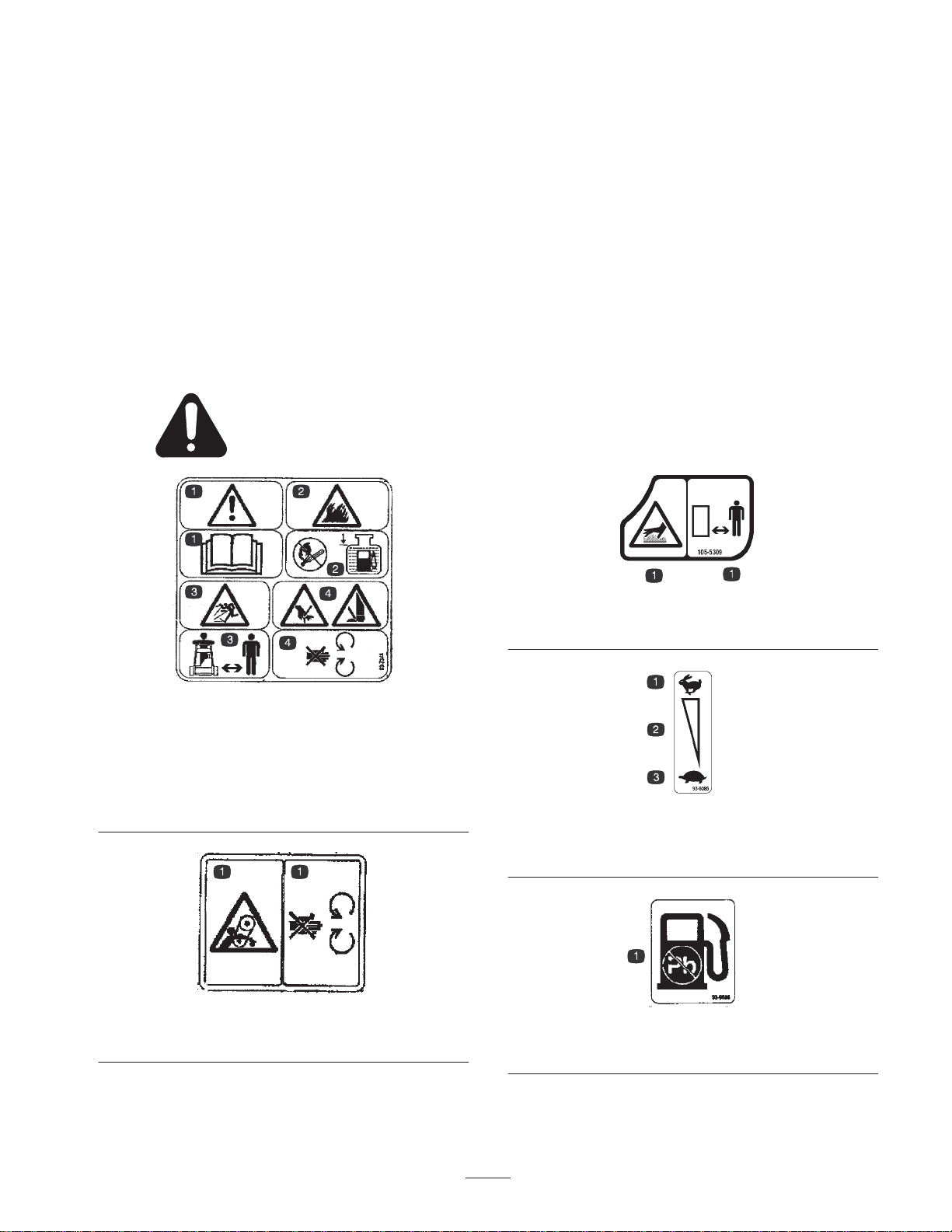
Safety and Instruction Decals
Safety decals and instructions are easily visible to the operator and are located near any
area of potential danger. Replace any decal that is damaged or lost.
Vibration Level
This unit has a hand–arm vibration level of 4.50 m/s
based on measurements of identical machines per ISO
5349 procedures.
2,
Part No. 93-7348
1. Danger—read the operator’s manual.
2. Fire or open flame—sparks, flame, and smoking prohibited. Fill
the fuel tank no higher than to the bottom of the filler neck.
3. Thrown object hazard—keep bystanders away.
4. Cutting hazard to fingers, hands, and feet—do not open or
remove safety shields while engine is running.
Part No. 93-9356
1. Entanglement hazard—stay away from moving parts.
Part No. 105–5309
1. Hot surface hazard—stay away.
Part No. 93-6085
1. Fast
2. Variable speed
Part No. 93-9886
1. Use unleaded fuel only.
3. Slow
7
Page 8
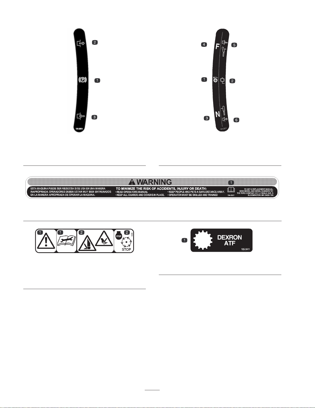
Part No. 104-2618
1. Parking brake
2. Parking
brake–disengaged
1. Read operator’s manual
3. Parking brake–engaged
Part No. 104–2621
1. Traction drive
2. Reel drive
3. Neutral
Part No. 104-2617
4. Forward
5. Lever–engaged
6. Lever–disengaged
1. Danger—read the
operator’s manual before
performing maintenance.
Part No. 93-8064
2. Cutting hazard to hands,
fingers, and feet—stop the
engine before going near
rotating reels.
Part No. 105–2411
1. Transmission oil
8
Page 9

Specifications
General Specifications
Kawasaki, 4-cycle, 3.7 (2.7 kw) air cooled OHV engine, 3600 RPM, 7.57 cu in.
Engine
Fuel capacity 2.64 qt. (2.5 l); regular grade unleaded gasoline
Traction/implement drive
(124 cc) displacement, cast iron cylinder sleeve; electronic ignition with integral
lighting coil; maximum noise suppression muffler; 83 dB(A) at operator ’s ear
Integral gearbox assembly directly mounted to the engine. The traction drive
consists of a constant mesh planetary gear reduction incorporating a wet bath
band-type clutch and brake driving a Peerless differential assembly integrated into
the gearbox assembly. The implement drive is a constant mesh gear driven
countershaft with integral cone wet clutch.
Ground speed
Traction drum Dual cast aluminum, 7.5 in. (19 cm) diameter tapered on outer 1/3 of length
Controls
Handle
Optional Transport tires
Reel construction
Suspension
Width of cut 21 in. (53.3 cm)
Height of cut 1/16 to 19/64 in. (1.5 to 7.5 mm) with Micro–Cut bedknife
Clip frequency
Bedknife/bedbar
Mowing speed: 1.3 to 3.5 MPH (2.1 to 5.6 km/h)
Transport speed: 5.3 MPH (8.5 km/h) maximum
Engine mounted on/off switch, recoil starter, and choke; handle mounted throttle
lever, dual function traction/reel control lever, service/parking brake lever; safety
devices include neutral interlock system, service/parking brake, enclosed
Loop style; 1 in. (2.5 cm) diameter with easy pull pin height adjustment, operator
selected
Two quick detachable pneumatic tires; 3.00/3.25 x 6, 3.25 in. (8.25 cm) tread width;
15 psi (1.03 bars) tire pressure
5 in. (12.7 cm) diameter, 11 high strength, low allow steel blades, through
hardened, impact resistant
Semi-floating cutting unit separable from drive unit pivoting around reel centerline
(pitch axis) and pivoting around bedknife centerline side to side (roll axis)
11 blade (standard): .16 in. (4.1 mm)
11 blade w/clip kit: .14 or .21 in. (3.5 or 6.4 mm)
Dual screw adjustment to reel; bedknife is high carbon through-hardened steel;
micro–cut bedknife standard
Grass basket
Rollers
Dry weight
Molded polyethylene with integrated graphics highlighting overlap guidelines;
vented for high efficiency collection
Front roller: aluminum Wiehle, 2.5 in. (6.35 cm) diameter, .20 spacing, with sealed
bearings and multi-lip seals standard
Rear roller: aluminum full roller, 2 in. (5.1 cm) diameter with sealed bearings and
multi-lip seals standard
250 lb. (114 kg) with aluminum Wiehle roller, kickstand and grass basket; without
transport tires and groomer
9
Page 10

Dimensions
Width 35–1/4”
Height 40”
Length 54”
Optional Equipment
Transport Wheel Kit Model No. 04122
Light Kit Model No. 04058
Grooming Reel Kit Model No. 04201
11 Blade Cutting Unit Model No. 04200
Wiehle Roller (.92 spacing) Part No. 99-6215
Tournament Bedknife Part No. 93-4263
1/8 in. Bedknife Part No. 93-4264
Clip Kit Part No. 105–5325
Hour Meter Kit Part No. 105–5350
Spark Arrester Kit Part No. 98-3426
High Altitude Jet
(for altitudes of 3000 to 6000 ft.)
High Altitude Jet
(for altitudes above 6000 ft.)
Extended Micro–cut Part No. 104–7720
Operator Presence Kit Part No. 105–5333
8 Blade Reel Assembly Part No. 105–2400
Full Roller Part No. 104–9796
Part No. 98-8735
Part No. 98-8736
10
Page 11

Setup
Note: Determine the left and right sides of the machine from the normal operating position.
Loose Parts Chart
Note: Use this chart as a checklist to ensure all parts necessary for assembly have been shipped. If any of these parts are
missing, total setup cannot be completed.
Description Qty. Use
Grass basket 1 Install on the machine.
Operator’s manual 1 Read before operating the machine.
Engine operator’s manual 1 Read before operating the machine.
Parts catalog 1
Operator video 1 View before operating the machine
Certificate of compliance 1
Registration cards 2 Fill out and return to Toro.
Installing the Handle
1. Remove the flange lock nut from the capscrew and
pivot pin on each side of the mower (Fig. 3).
2
1
Figure 3
1. Flange lock nut 2. Pivot pin
2. Insert the handle ends through the slots in the handle
support arms (Fig. 4).
3. Squeeze the handle ends inward and install them on
the step of the pivot pin (Fig. 4).
3
1
2
4
Figure 4
1. Left handle end
2. Support arm
4. Secure the handle to the capscrew and pivot pin with
the flange lock nut (Fig. 4).
5. Locate cable tie loosely securing throttle cable to wire
harness. Position cable tie approximately one inch
behind transmission and tighten cable tie.
3. Pivot pin
4. Locknut
11
Page 12

Adjusting the Handle
1. Remove hairpin cotters from ring pins on each side of
mower (Fig. 5).
1
3. Pivot wheel locking clip away from center of wheel
allowing wheel to slide farther onto axle (Fig. 7).
4. Rotate wheel back and forth until it slides completely
onto axle and locking clip is secured in groove on axle
shaft.
Figure 5
1. Ring pins
2. While supporting handle, remove ring pins from each
side and raise or lower handle to desired operating
position (Fig. 5).
3. Reinstall ring pins and hair pin cotters.
Installing the Transport Wheels
1. Push kick stand down with foot and pull up on handle
to support mower on kick stand.
2. Apply Anti–Seize lubricant to the exposed ends of
axles and slide wheel onto axle (Fig. 6).
1
Figure 7
1. Locking clip
5. Repeat procedure on opposite side of machine.
6. Tires to be inflated to 12–15 psi.
1
1. Left axle shaft
Figure 6
12
Page 13

Before Operating
Adding Engine Oil
Crankcase must be filled with approximately 20 fluid
ounces of proper viscosity oil before staring. The engine
uses any high–quality oil having the American Petroleum
Institute — APl — “service classification” SF, SG, SH or
SJ. Oil viscosity — weight — must be selected according
to ambient temperature. Temperature/viscosity
recommendations are:
3. Wipe gauge clean and insert it into filler port. Then
remove and check level of oil. Do not screw into port.
If level is low, add only enough oil to raise level to
bottom of filler opening. Recheck level of oil. Do not
overfill.
Note: The Toro Company recommends that the oil level
be checked each time mower is used or after every 5
operating hours. Initially, change oil after the first 20
hours of operation; thereafter, change oil after every 50
hours of operation. More frequent oil changes are required
in dusty or dirty conditions.
–20°C –10°C
SAE 5W20
–4°F14°F
Note: Using multi-grade oils (5W-20, 10W-30, and
10W-40) will increase oil consumption. Check the oil
level more frequently when using them.
1. Position mower so the engine is level and clean around
oil level gauge (Fig. 8).
0°C 10°C 20°C
SAE 30
SAE 10W30/ SAE 10W–40
32°F 50°F 68 °F
30°C 40°C
SAE 40
86°F 104°F
Filling the Fuel Tank
Important Never use methanol, gasoline containing
methanol, gasohol containing more than 10% ethanol,
gasoline additives, premium gasoline, or white gas
because the fuel system could be damaged. Do not mix oil
with gasoline.
1
2
Figure 9
1. Fuel tank cap 2. Fuel gauge
1
Figure 8
1. Oil level gauge
2. Remove gauge by rotating counterclockwise.
Warning
Gasoline is harmful or fatal if swallowed.
Long-term exposure to vapors can cause serious
injury and illness.
• Avoid prolonged breathing of vapors.
• Keep face away from nozzle and gas tank or
conditioner opening.
• Keep gas away from eyes and skin.
13
Page 14

Danger
In certain conditions, gasoline is extremely
flammable and highly explosive. A fire or
explosion from gasoline can burn you and others
and can damage property.
• Fill the fuel tank outdoors, in an open area,
when the engine is cold. Wipe up any gasoline
that spills.
• Do not fill the fuel tank completely full. Add
gasoline to the fuel tank until the level is 1/4 to
1/2 in. (6 to 13 mm) below the bottom of the
filler neck. This empty space in the tank allows
gasoline to expand.
• Never smoke when handling gasoline, and stay
away from an open flame or where gasoline
fumes may be ignited by a spark.
• Store gasoline in an approved container and
keep it out of the reach of children. Never buy
more than a 30-day supply of gasoline.
• Always place gasoline containers on the ground
away from your vehicle before filling.
• Do not fill gasoline containers inside a vehicle
or on a truck or trailer bed because interior
carpets or plastic truck bed liners may insulate
the container and slow the loss of any static
charge.
• When practical, remove gas–powered
equipment from the truck or trailer and refuel
the equipment with its wheels on the ground.
• If this is not possible, then refuel such
equipment on a truck or trailer from a portable
container, rather than from a gasoline
dispenser nozzle.
• If a gasoline dispenser nozzle must be used,
keep the nozzle in contact with the rim of the
fuel tank or container opening at all times until
fueling is complete.
Important Use only Dexron lll or equivalent
transmission fluids. Other fluids could cause system
damage.
1. Place the mower on its drums on a level surface.
2. Remove the check/fill plug from the right-hand side of
the transmission (Fig. 10). The oil level should come
to the bottom of the fill hole. If it does not, add enough
of the proper oil type until the level reaches the bottom
of the fill hole.
1
2
Figure 10
1. Check/fill plug 2. Drain plug
3. Install the plug.
Separating the Cutting Unit
from the Traction Unit
1. Place the mower on its drums on a level surface.
2. Lower kick stand. Insert a 1/4” dia. pin or equivalent
into frame hole above kick stand mounting bolt
(Fig. 11).
1. Clean around fuel tank cap and remove cap from tank
(Fig. 9). Using unleaded gasoline, fill fuel tank no
higher than to bottom of filter screen. Do not overfill.
2. Install fuel tank cap and wipe up any spilled gasoline.
Checking the Transmission
Fluid
The transmission is filled at the factory with
approximately 94 fluid ounces of Dexron lll automatic
transmission fluid. Check fluid level before the engine is
first started and every 50 hours thereafter.
Note: The seals used in the transmission are internally
lubricated with grease. During initial operation of mower,
slight weeping of grease from these seals will occur. Wipe
off excess grease.
2
1
Figure 11
1. Kick stand 2. 1/4” Pin
3. Remove grass basket.
4. Remove (2) capscrews securing cutting unit pivot arms
to traction unit frame tube (Fig. 12).
14
Page 15

3. Firmly press down on cutting unit and maintain
1
3
1
3
2
pressure on rear roller. Try inserting a piece of paper
under each end of the roller. If the gap is greater than
the piece of paper, on either end, an adjustment may
be required, proceed to step 4.
4. Loosen locknuts securing right rear roller bracket to
cutting unit sideplate (Fig. 14).
Figure 12
1. Cutting unit pivot arms
2. Traction unit frame tube
5. Rotate pivot arms forward (Fig. 12) and rest traction
unit on restrained kickstand.
6. Pull cutting unit forward about 2 in. (51 mm) and then
to the right to disengage the transmission coupling
(Fig. 12).
1
3. Capscrews
2
1
Figure 14
1. Right rear roller bracket 2. Locknuts
5. While holding reel securely on plate and maintaining
pressure on rear roller, rotate lower right roller
mounting bolt (Fig. 15). This mounting bolt has an
offset, which when rotated, acts as an eccentric (cam)
to raise or lower the roller. There is an I.D. dot which
denotes the offset of the bolt. Dot indicates in which
direction right end of roller moves when bolt is turned
and should always be in the rear half of the arc as
shown in figure 15.
1
Figure 13
1. Transmission coupling 2.
7. Reverse procedure to install cutting unit.
Leveling the Rear Roller to the
Reel
1. Position cutting unit on a flat, level surface preferably
a precision ground surface plate.
2. Place a 1/4 in. (6.4 mm) or thicker plate under the reel
blades and against front edge of bedknife.
Note: Be sure the plate covers the full length of the reel
blades and three blades contact.
Figure 15
1. Eccentric bolt
Note: If additional adjustment is required, replace the
screw on the left-hand bracket with another eccentric bolt,
Part No. 105–3833. Ensure both rear roller brackets are in
the same hole.
6. To verify if roller is level, try inserting a piece of
paper under each end of roller.
15
Page 16

7. When roller is level, tighten nuts securely.
Adjusting the Bedknife to the
Reel
Note: Each time adjusting screw is rotated one click
clockwise, bedknife moves .0007 in. closer to reel. Do not
overtighten the adjusting screws.
4. Check for light contact at other end of reel using paper
and adjust as required.
Bedknife to reel adjustment is accomplished by loosening
or tightening bedbar adjusting screws, located on top of
mower.
1. Position machine on a flat, level work surface. Make
sure reel contact is removed by turning bedbar
adjusting screws counterclockwise (Fig. 16).
1
Figure 16
1. Bedbar adjusting screw
2. Tilt mower on back to expose bedknife and reel.
3. At one end of reel, insert a long strip of newspaper
between reel and bedknife (Fig. 17). While slowly
rotating reel forward, turn bedbar adjusting screw
clockwise (on same end of reel, one click at a time,
until paper is pinched lightly, when inserted from the
front, parallel to the bedknife. A slight drag will be
noted as the paper is pulled (Fig. 16).
5. After adjustment is accomplished, check to see if reel
can pinch paper when inserted from the front and cut
paper when inserted at a right angle to the bedknife
(Fig. 17). It should be possible to cut paper with
minimum contact between the bedknife and the reel
blades. Should excessive reel drag be evident it will be
either necessary to backlap or regrind the cutting unit
to achieve the sharp edges needed for precision cutting
(see Toro reel sharpening manual).
Adjusting the Height of Cut
1. Adjust rear roller brackets (Fig. 18) to upper or lower
position depending on desired height of cut range.
• The upper position (factory setting) is used when
height of cut settings range from 1/16 to 5/32”.
• The lower position is used when height of cut settings
range from 1/8” to 19/64”.
2. Verify that rear roller is level and that bedknife to reel
contact is correct. Tip mower on back to expose front
and rear rollers and bedknife.
3. Loosen locknuts securing height-of-cut arms to
cutting unit side plates (Fig. 18).
4
1
3
Figure 17
1. Rear roller bracket
2. Height-of-cut arm
16
2
Figure 18
3. Locknut
4. Adjusting screw
Page 17

4. Loosen nut on gauge bar (Fig. 19) and set adjusting
screw to desired height-of-cut. Distance between
bottom of screw head and face of bar is height-of-cut.
2
1
3
Figure 19
1. Gauge ba r
2. Height adjusting screw
5. Hook screw head on cutting edge of bedknife and rest
rear end of bar on rear roller (Fig. 20).
3. Nut
1
Figure 21
1. Cut-off b a r
2. Insert .060 inch feeler gauge between top of reel and
bar and tighten screws. Ensure bar and reel are equal
distance apart across complete reel.
Note: The bar is adjustable to compensate for changes in
turf conditions. The bar should be adjusted closer to reel
when turf is extremely dry. By contrast, adjust bar further
away from reel when turf conditions are wet. The bar
should be parallel to reel to ensure optimum performance
and should be adjusted whenever reel is sharpened on a
reel grinder.
Figure 20
6. Rotate adjusting screw until roller contacts front of
gauge bar. Adjust both ends of roller until entire roller
is parallel to the bedknife.
Important When set properly, the rear and front
rollers will contact the gauge bar and the screw will be
snug against the bedknife. This ensures that the
height-of-cut is identical at both ends of the bedknife.
7. Tighten nuts to secure adjustment.
Adjusting the Cut-Off Bar
Adjust cut–off bar to assure clippings are cleanly
discharged from the reel area:
1. Loosen screws securing top bar (Fig. 21) to cutting
unit.
Installing the Grass Basket
Grasp basket by top lip and slide basket frame into the
receivers (Fig. 22).
2
1
Figure 22
1. Grass basket 2. Basket receivers
17
Page 18

Checking the Interlock Switch
Operation
1
Caution
If safety interlock switches are disconnected or
damaged the machine could operate unexpectedly
causing personal injury.
• Do not tamper with the interlock switches.
• Check the operation of the interlock switches
daily and replace any damaged switches before
operating the machine.
• Replace switches every two years regardless of
whether they are operating properly or not.
1. Push kick stand down with foot and pull up on handle
to support mower on kick stand.
2. Place traction lever into Engage position and engine
controls in starting position.
3. Attempt to start engine. Engine should not start. If
engine starts, the interlock switch needs service.
Correct problem before operating. Refer to Servicing
Interlock Switch, page 30.
Operation
Note: Determine the left and right sides of the machine
from the normal operating position.
2
3
Figure 23
1. Throttle control
2. Traction & reel drive
engagement lever
3. Service/parking brake
Traction and Reel Drive Engagement
Lever
The traction and reel drive engagement lever (Fig. 23) is
located on front right side of control panel. Traction lever
has two positions: Neutral and Forward. Pushing lever
forward engages traction drive.
The reel drive lever has two positions: Engage and
Disengage. Move top of lever to the left to engage reel or
back to neutral to disengage reel.
Think Safety First
Please carefully read all of the safety instructions and
decals in the safety section. Knowing this information
could help you or bystanders avoid injury.
Controls
Throttle Control
The throttle control (Fig. 23) is located on rear right side
of control panel. Lever connects to and operates throttle
linkage to carburetor. Engine speed can be varied from
2400 RPM to 3600 RPM.
Service/Parking Brake
The service/parking brake (Fig. 23) is located on left front
side of control panel. Use brake to slow or stop machine.
The brake can also be used as a parking brake. Pulling the
lever back over center will set the parking brake. Brake
must be released before traction drive is engaged.
Operator Presence Control
The optional operator presence control must be engaged
before engaging the traction lever or the engine will stop.
Choke Lever
The choke lever (Fig. 24) is located on left front of
engine. Lever has two positions: Run and Choke. Move
lever to Choke position when starting a cold engine. After
engine starts move lever to Run position.
18
Page 19

1
2
Figure 24
1. Choke lever 2. Fuel shut-off valve
Fuel Shut-Off Valve
The fuel shut-off valve (Fig. 24) is located on left front of
engine. Valve has two positions: Closed and Open. Move
lever to closed position when storing or transporting
machine. Open valve before starting engine.
Recoil Starter
Pull recoil starter handle (Fig. 25) to start engine.
1
1
Figure 26
1. Kick stand
Starting and Stopping
Note: Make sure spark plug wire is installed on spark
plug.
1. Make sure traction and reel drive levers are in
Disengaged position.
Note: Engine will not start if traction lever is in the
engaged position.
2. Open fuel shut-off valve on engine (Fig. 24).
2
Figure 25
1. Recoil starter 2. On/off switch
On/Off Switch
The on/off switch (Fig. 25) is located on rear of engine.
Move switch to On position to start engine and Off to stop
engine.
Kickstand
The kickstand (Fig. 26) is mounted to rear of machine and
is used to raise rear of machine for installation or removal
of transport wheels.
3. Move on/off switch (Fig. 25 ) to On position.
4. Move throttle control (Fig. 23) to Fast position.
5. Move choke lever (Fig. 24) to half-open position when
starting a cold engine. Choke may not be required
when starting a warm engine.
6. Pull recoil starter handle out until positive engagement
results, then pull vigorously to start engine. Open
choke as engine warms up.
Important Do not pull recoil rope to its limit or let go
of starter handle when rope is pulled out because rope
may break or recoil assembly may be damaged.
7. To stop engine during operation, move traction and
reel drive controls to Disengaged position, throttle
control to Slow and on/off switch to Off.
8. Pull spark plug wire off spark plug to prevent the
possibility of accidental starting before storing
machine.
9. Close fuel shut-off valve before storing or transporting
mower in a vehicle.
19
Page 20

Transport Operation
1. Push kickstand down with foot and pull up on handle
to raise rear of mower and install transport wheels.
2. To release kickstand, pull up on handle and lower rear
of mower onto transport wheels.
3. Ensure traction and reel drive controls are in
Disengage position and start engine.
4. Set throttle control to Slow, tip front of machine up
gradually engage traction drive and slowly increase
engine speed.
5. Adjust throttle to operate mower at desired ground
speed and transport mower to desired destination.
Preparing to Mow
1. Return traction control lever to Disengage, throttle to
Slow and stop engine.
2. Push kickstand down with foot and pull up on handle
to raise wheels off the ground.
3. Remove transport wheels.
4. Release kickstand.
Method of Mowing
The greens should be mowed in a straight back and forth
direction across the green. Avoid circular mowing or
turning the mower on greens areas since scuffing may
occur. Turning the mower should be done off the green by
raising the cutting reel (pushing the handle down) and
turning on the traction drum. Mowing should be done at a
normal walking pace. Fast speeds saves very little time
and will result in an inferior mowing job.
To assist in maintaining a straight line across the green
and to keep the machine an equal distance from the edge
of the previous cut, use the alignment stripes on the basket
(Fig. 27).
1
Mowing Operation
Proper use of the machine provides the smoothest turf
cutting available.
Important Grass clippings act as a lubricant when
mowing. Excessive operation of the cutting unit with the
absence of grass clippings can damage the cutting unit.
Prior to Mowing
Be sure the mower is carefully adjusted and is set evenly
on both sides of the reel. Improper mower adjustment is
magnified in the appearance of the clipped turf. Remove
all foreign objects from turf prior to mowing. Make sure
everyone, especially children and pets, are clear of the
work area.
Figure 27
1. Alignment stripes
Control Operation
To operate the controls while mowing:
1. Start the engine, set the throttle at reduced speed, push
down on handle to raise cutting unit, move traction
lever to Engaged position and transport mower onto
collar of green (Fig. 28).
2. Move traction lever to Disengaged position and
Engage reel drive lever (Fig. 28).
20
Page 21

1
2
throttle speed until the mower is traveling at the
desired ground speed, drive the mower out onto the
green area, lower the front of the mower down and
commence operation (Fig. 28).
After Mowing
1. Drive off green, move reel drive and traction control
levers to Disengage and stop the engine.
2. Empty the grass catcher of clippings, install grass
catcher and commence transport operation; refer to
Transport Operation, page 20.
4
3
3. Move traction lever to Engaged position, increase
1. Traction drive –neutral
2. Traction drive neutral &
reel drive off
Figure 28
3. Traction drive–engaged
(transport)
4. Traction drive & reel drive
engaged
21
Page 22

Maintenance
Note: Determine the left and right sides of the machine from the normal operating position.
Recommended Maintenance Schedule
Maintenance Service
Interval
After first 20 hours
After first 50 hours • Change the transmission fluid.
Every 25 hours
Every 50 hours
Every 100 hours
Every 200 hours
Every 2 years
Maintenance Procedure
• Change the engine oil.
• Clean the fuel filter.
• Service the air filter pre-cleaner.
• Check for loose fasteners.
• Clean the fuel filter and sediment bowl.
• Change the engine oil.
• Check the transmission fluid level.
• Check the cut-off bar adjustment.
• Service the air cleaner filter.
• Check the gear case oil level.
• Clean the combustion chamber.
• Replace the spark plug.
• Adjust the valves and torque the head bolts.
• Replace safety interlock switch.
• Change the transmission fluid.
Important Refer to your engine operator’s manual for additional maintenance procedures.
22
Page 23

Daily Maintenance Checklist
Duplicate this page for routine use.
For the week of:
Maintenance Check Item
Check the safety interlock operation.
Check the parking brake operation.
Check that pivot joints operate freely.
Check the fuel level.
Check the engine oil level.
Check the air filter.
Clean the engine cooling fins.
Check for unusual engine noises.
Check for unusual operating noises.
Check the reel-to-bedknife adjustment.
Check the height-of-cut adjustment.
Touch up damaged paint.
Notation for Areas of Concern
Inspection performed by:
Item Date Information
1
Mon. Tues. Wed. Thurs. Fri. Sat. Sun.
2
3
4
5
6
7
8
23
Page 24

Engine Oil
Check the engine oil level each time the mower is used or
after every 5 operating hours. Change the oil after the first
20 operating hours and every 50 hours thereafter. More
frequent oil changes are required in dusty or dirty
conditions.
3. Push down on handle to tip mower and engine
backward, allowing more oil to run into drain pan.
4. Install drain plug and refill crankcase with proper oil;
refer to Checking the Oil Level, page 24.
Servicing the Air Cleaner
Checking the Oil Level
1. Position mower so the engine is level and clean around
oil level gauge (Fig. 29).
1
2
Figure 29
1. Oil level gauge 2. Drain plug
Normally, clean air cleaner after every 25 operating hours.
More frequent cleaning is required when mower is
operated in dusty or dirty conditions.
1. Make sure wire is off spark plug.
2. Remove wing nuts securing air cleaner cover to air
cleaner and remove cover. Clean cover thoroughly
(Fig. 30).
1
2. Remove oil level gauge by rotating it
counterclockwise.
3. Wipe oil level gauge clean and insert it into filler port.
Do not screw into port. Then remove and check level
of oil. If level is low, add only enough oil to raise level
to bottom of filler opening. Recheck level of oil. Do
not overfill.
4. Reinstall oil level gauge and wipe up any spilled oil.
Changing the Oil
1. Start and run engine for a few minutes to warm the
engine oil.
2. Place a drain pan at rear of machine under drain plug
(Fig. 29). Remove drain plug.
Figure 30
1. Air cleaner cover
3. If foam element is dirty, remove it from paper element
(Fig. 31). Clean thoroughly.
A. Wash foam element in a solution of liquid soap and
warm water. Squeeze to remove dirt, but do not
twist because foam may tear.
B. Dry by wrapping in a clean rag. Squeeze rag and
foam element to dry.
C. Saturate element with clean engine oil. Squeeze
element to remove excess oil and to distribute oil
thoroughly. An oil damp element is desirable.
24
Page 25

3. Set air gap at 0.028–0.032 in. (Fig. 33). Install
correctly gapped spark plug and tighten firmly to
1
17 ft.-lb.
2
Figure 31
1. Foam element 2. Paper element
4. When servicing foam element, check condition of
paper element. Clean or replace as required.
5. Install foam element, paper element, and air cleaner
cover.
Important Do not operate the engine without the air
cleaner element because extreme engine wear and damage
will likely result.
Replacing the Spark Plug
0.028-0.032 in.
Figure 33
Cleaning the Fuel Filter
Initially, clean fuel filter after the first 20 hours of
operation; thereafter clean after every 50 hours operation.
1. Close fuel shut off valve and unscrew bowl from filter
body (Fig. 34).
Use an NGK BPR 5ES spark plug or equivalent. Correct
air gap is 0.028–0.032 in. Remove plug after every 100
operating hours and check its condition.
1. Pull wire off spark plug (Fig. 32).
2. Clean around spark plug and remove plug from
cylinder head.
1
Figure 32
1. Spark plug wire
Important Replace a cracked, fouled, or dirty spark
plug. Do not sand blast, scrape, or clean electrodes
because engine damaged could result from grit entering
the cylinder.
1
2
Figure 34
1. Shut-off valve 2. Bowl
2. Clean bowl and filter in clean gasoline and install.
Changing the Transmission
Fluid
The fluid level in the transmission should be checked at
50 hour intervals; refer to Checking the Transmission
Fluid, page 14. Change the transmission fluid after the
first 50 hours of operation and every 2 years thereafter.
Important Use only Dexron lll or equivalent
transmission fluids. Other fluids could cause system
damage.
1. Place a drain pan at the rear of the machine.
25
Page 26

2. Remove the drain plug from the rear of the
transmission (Fig. 35).
2
1
1
Figure 36
1. Belt cover
Figure 35
1. Check/fill plug 2. Drain plug
3. Push down on the handle and tip the machine back.
Remove the check/fill plug from the right-hand side of
the transmission (Fig. 35).
4. When the fluid is drained, install the drain plug.
5. Place the mower on its drums on a level surface.
6. Fill the transmission with approximately 94 fluid
ounces of the proper type of transmission fluid until
the level reaches the bottom of the check/fill hole;
refer to Checking the Transmission Fluid, page 14, for
proper oil type.
7. Install the check/fill plug.
Adjusting the Belts
Make sure belts are properly tensioned to assure proper
operation of the machine and unnecessary wear. Check
belts frequently.
Reel Drive Belt (Reel)
1. Remove the belt cover mounting fasteners and belt
cover to expose belt (Fig. 36).
2. Check tension by depressing belt (Fig. 37) at mid span
of pulleys with 4 ± 1 lb. of force. Belt should deflect
1/4 in. If deflection is incorrect, proceed to next step.
1
Figure 37
1. Reel drive belt
3. To adjust belt tension:
A. Loosen the bearing housing mounting nuts
(Fig. 38).
26
Page 27

2
1
Figure 38
1. Reel drive belt 2. Bearing housing mounting
nuts
Reel Drive Belt (Transmission coupler)
1. Remove the belt cover mounting fasteners and belt
cover to expose belt (Fig. 40).
1
B. Using a 3/8 in. drive torque wrench, rotate the
bearing housing with 35–40 in.-lb. of torque to set
belt tension (Fig. 39)
1
2
Figure 39
1. Bearing h o u s i n g 2. 3/8” T orque wrench here
C. Tighten the bearing housing mounting nuts
(Fig. 38). Do not over-tension belt.
Figure 40
1. Belt cover
2. Check tension by depressing belt (Fig. 41) at mid span
of pulleys with 4 ± 1 lb. of force. Belt should deflect
1/4 in. If deflection is incorrect, proceed to next step.
1
Figure 41
1. Reel drive belt
D. Install belt cover.
27
Page 28

3. To adjust belt tension:
A. Loosen the bearing housing mounting nuts
(Fig. 38).
2
1
Figure 42
1. Reel drive belt 2. Bearing housing mounting
nuts
B. Using a 3/8 in. drive torque wrench, rotate the
bearing housing with 35–40 in.-lb. of torque to set
belt tension (Fig. 39).
Traction Drive Belt
1. Remove belt cover mounting fasteners and belt cover
to expose belt (Fig. 44).
1
Figure 44
1. Traction drive belt cover
2. Check tension by depressing belt (Fig. 45) at mid span
of pulleys with 4 ± 1 lb. of force. Belt should deflect
1/4 in. If deflection is incorrect, proceed to next step.
1
2
Figure 43
1. Bearing h o u s i n g 2. 3/8” T orque wrench here
C. Tighten the bearing housing mounting nuts
(Fig. 38). Do not over-tension belt.
D. Install belt cover.
1
Figure 45
1. Traction drive belt
3. To adjust belt tension:
A. On back side of side plate, loosen the capscrew
securing the idler bracket to the side plate
(Fig. 46).
28
Page 29

3. Tighten front cable jam nut.
4. Check control operation.
1
2
1
Figure 46
1. Idler bracket capscrew
2
3
1
Figure 47
1. Traction drive belt 2. Torque here
B. Using a 3/8 in. drive torque wrench, rotate the idler
bracket with 35–40 in.-lb. of torque to set belt
tension (Fig. 47). Tighten the idler bracket
mounting capscrew. Do not over-tension belt.
C. Install belt cover.
Adjusting the Traction Control
If traction control does not engage or it slips during
operation, an adjustment is required.
Figure 48
1. Traction cable 2. Service/parking brake
cable
Adjusting the Service/Parking
Brake
If service/park brake slips when operated, an adjustment is
required.
1. Move service/parking brake lever to Off position.
2. To increase cable tension, loosen front cable jam nut
and tighten back cable jam nut (Fig. 48) until a force
of 6–9 lb. is required to engage brake. Force to be
measured at lever knob. Do not over adjust, or brake
band may drag.
Adjusting the Reel Control
If reel control does not engage or it slips during operation,
an adjustment is required.
1. Make sure traction control is properly adjusted; refer
to Adjusting the Traction Control, page 29.
2. To increase cable tension, loosen front cable jam nut
and tighten back cable jam nut (Fig. 49) (located on
top of gear box) until the reel cable force adds 7 to 10
lbs. of additional handle force measured at the control
knob.
Note: If traction control handle force is 12 lbs., the
combined traction and reel force should be 19 to 22 lbs.
1. Move traction control to Disengaged position.
2. To increase cable tension, loosen front cable jam nut
and tighten back cable jam nut (Fig. 48) until a force
of 12–16 lb. is required to engage traction control.
Force to be measured at control knob.
29
Page 30

Servicing the Bedbar
Removing the Bedbar
1. Turn bedbar adjuster screw, counterclockwise, to back
bedknife away from reel (Fig. 51).
1
Figure 49
1. Reel control cable
3. Tighten front cable jam nut.
4. Check control operation.
Servicing the Interlock Switch
Use the following procedure should the switch need
adjustment or replacement.
1. Make sure the engine is off and traction lever is
Disengaged.
2. Engage traction lever until it contacts neutral stop
(Fig. 50).
2
1
4
4
1. Bedbar adjusting screw
2. Spring tension nut
3. Bedbar
12
3
5
Figure 51
4. Jam nut
5. Bedbar bolt
3
Figure 50
1. Traction lever
2. Neutral stop
3. Interlock switch
4. .032” Gap
3. Loosen interlock switch mounting fasteners (Fig. 50).
4. Place a .032” thick shim between the traction lever
and the interlock switch (Fig. 50).
5. Tighten interlock switch mounting fasteners. Recheck
gap. The traction lever must not contact the switch.
6. Engage traction lever and verify that the switch loses
continuity. Replace if required.
Important Replace interlock switch every 2 years.
2. Back out the spring tension nut, until the washer is no
longer tensioned against the bedbar (Fig. 51).
3. On each side of the machine, loosen the jam nut
securing the bedbar bolt (Fig. 51).
4. Remove each bedbar bolt allowing bedbar to be pulled
downward and removed from machine. Account for 2
nylon and 2 stamped steel washers on each end of
bedbar (Fig. 51).
Assembling the Bedbar
1. Install bedbar, positioning mounting ears between
washer and bedbar adjuster.
2. Secure bedbar to each side plate with bedbar bolts
(jam nuts on bolts) and 8 washers. A nylon washer is
to be positioned on each side of side plate boss. Place
a steel washer outside each of the nylon washers.
Torque bolts to 240–320 in.-lb. Tighten jam nuts until
thrust washers just rotate freely.
30
Page 31

3. Tighten spring tension nut until spring is collapsed,
then back off 1/2 turn.
2. Insert a 18 mm socket onto hex flange nut on left end
of reel shaft.
4. Adjust bedbar; refer to Adjusting the Bedknife to the
Reel, page 16.
Backlapping the Reel
1. Remove plug from the reel drive cover on the left side
of reel assembly (Fig. 52)
1
Figure 52
1. Reel drive cover plug
3. Backlap according to procedure in Toro Sharpening
Reel and Rotary Mowers Manual, Form No. 80-300
PT.
Danger
Contact with the reel or other moving parts can
result in personal injury.
• Stay away from the reel while backlapping.
• Never use a short handled paint brush for
backlapping. Part No. 29-9100 Handle assembly
complete or individual parts are available from
your local Authorized Toro Distributor.
Note: For a better cutting edge, run a file across the front
face of the bedknife when the lapping operation is
completed. This will remove any burrs or rough edges that
may have built up on the cutting edge.
4. Reinstall plug when backlap operation is completed.
31
Page 32

The Toro General Commercial Products Warranty
A Two-Year Limited Warranty
Conditions and Products Covered
The Toro Company and its affiliate, Toro Warranty Company,
pursuant to an a g r eement between them, jointly warrant your 1996
or newer Toro Commercial Product (“Product”) purchased after
January 1, 1997, to be free from defects in materials or
workmanship for tw o years or 1500 operational hours*, whichever
occurs first. Where a warrantable condition exists, we will repair the
Product at no cost to you including diagnosis, labor, parts, and
transportation. This warranty begins on the date the Product is
delivered to the original retail purchaser.
* Product equipped with hour meter
Instructions for Obtaining Warranty Service
You are responsible for notifying the Commercial Products
Distributor or Authorized Commercial Products Dealer from whom
you purchased the Product as soon as you believe a warrantable
condition exists.
If you need help locating a Commercial Products Distributor or
Authorized Dealer, or if you have questions regarding your
warranty rights or responsibilities, you may contact us at:
Toro Commercial Products Service Department
Toro Warranty Company
8111 Lyndale Avenue South
Bloomington, MN 55420-1196
952-888-8801 or 800-982-2740
E-mail: commercial.service@toro.com
Owner Responsibilities
As the Product owner, you are responsible for required maintenance and adjustments stated in your operator’s manual. Failure
to perform required maintenance and adjustments can be grounds
for disallowing a warranty claim.
Items and Conditions Not Covered
Not all product failures or malfunctions that occur during the
warranty period are defects in materials or workmanship. This
express warranty does not cover the following:
• Product failures which result from the use of non-Toro
replacement parts, or from installation and use of add-on,
modified, or unapproved accessories
• Product failures which result from failure to perform required
maintenance and/or adjustments
• Product failures which result from operating the Product in an
abusive, negligent or reckless manner
• Parts subject to consumption through use unless found to be
defective. Examples of parts which are consumed, or used up,
during normal Product operation include, but are not limited to,
blades, reels, bedknives, tines, spark plugs, castor wheels,
tires, filters, belts, etc.
• Failures caused by outside influence. Items considered to be
outside influence include, but are not limited to, weather,
storage practices, contamination, use of unapproved coolants,
lubricants, additives, or chemicals, etc.
• Normal “wear and tear” items. Normal “wear and tear” includes,
but is not limited to, damage to seats due to wear or abrasion,
worn painted surfaces, scratched decals or windows, etc.
Parts
Parts scheduled for replacement as required maintenance are
warranted for the period of time up to the scheduled replacement
time for that part.
Parts replaced under this warranty become the property of Toro.
T oro will make the final decision whether to repair any existing part
or assembly or replace it. Toro may use factory remanufactured
parts rather than new parts for some warranty repairs.
General Conditions
Repair by an Authorized Toro Distributor or Dealer is your sole
remedy under this warranty.
Neither The Toro Company nor Toro Warranty Company is
liable for indirect, incidental or consequential damages in
connection with t h e use of the Toro Products covered by this
warranty, including any cost or expense of providing substitute equipment or service during reasonable periods of
malfunction or non-use pending completion of repairs under
this warranty. Except for the Emissions warranty referenced
below, if applicable, there is no other express warranty. All
implied warranties of merchantability and fitness for use are
limited to the duration of this express warranty.
Some states do not allow exclusions of incidental or consequential
damages, or limitations on how long an implied warranty lasts, so
the above exclusions and limitations may not apply to you.
This warranty gives you specific legal rights, and you may also
have other rights which vary from state to state.
Note regarding engine warranty: The Emissions Control System
on your Product may be covered by a separate warranty meeting
requirements established by the U.S. Environmental Protection
Agency (EPA) and/or the California Air Resources Board (CARB).
The hour limitations set forth above do not apply to the Emissions
Control System Warranty. Refer to the Engine Emission Control
Warranty Statement printed in your operator’s manual or contained in the engine manufacturer’s documentation for details.
Countries Other than the United States or Canada
Customers who have purchased Toro products exported from the United States or Canada should contact their Toro Distributor (Dealer)
to obtain guarantee policies for your country, province, or state. If for any reason you are dissatisfied with your Distributor’s service or
have difficulty obtaining guarantee information, contact the Toro importer. If all other remedies fail, you may contact us at Toro W arranty
Company.
Part No. 374-0031 Rev. –
 Loading...