

Page 1

FormNo.3367-381RevB
Greensmaster
®
Flex18orFlex21
Walk-BehindMower
ModelNo.04019—SerialNo.311000001andUp
ModelNo.04024—SerialNo.311000001andUp
ModelNo.04025—SerialNo.311000001andUp
ToregisteryourproductordownloadanOperator'sManualorPartsCatalogatnocharge,gotowww.T oro.com.OriginalInstructions(EN)
Page 2
ThisproductcomplieswithallrelevantEuropean
directives,fordetailspleaseseetheseparateproduct
specicDeclarationofConformity(DOC)sheet.
WARNING
CALIFORNIA
Proposition65Warning
Theengineexhaustfromthisproduct
containschemicalsknowntotheStateof
Californiatocausecancer,birthdefects,
orotherreproductiveharm.
Important:Thisengineisnotequippedwitha
sparkarrestermufer.ItisaviolationofCalifornia
PublicResourceCodeSection4442touseoroperate
theengineonanyforest-covered,brush-covered,or
grass-coveredland.Otherstatesorfederalareas
mayhavesimilarlaws.
ThissparkignitionsystemcomplieswithCanadian
ICES-002.
Introduction
Thismachineisawalk-behind,reel-bladelawnmower
intendedtobeusedbyprofessional,hiredoperatorsin
commercialapplications.Itisprimarilydesignedfor
cuttinggrassonwell-maintainedlawnsinparks,golf
courses,sportselds,andoncommercialgrounds.Itis
notdesignedforcuttingbrush,mowinggrassandother
growthalongsidehighways,orforagriculturaluses.
Readthisinformationcarefullytolearnhowtooperate
andmaintainyourproductproperlyandtoavoidinjury
andproductdamage.Youareresponsibleforoperating
theproductproperlyandsafely.
YoumaycontactTorodirectlyatwww .Toro.comfor
productandaccessoryinformation,helpndinga
dealer,ortoregisteryourproduct.
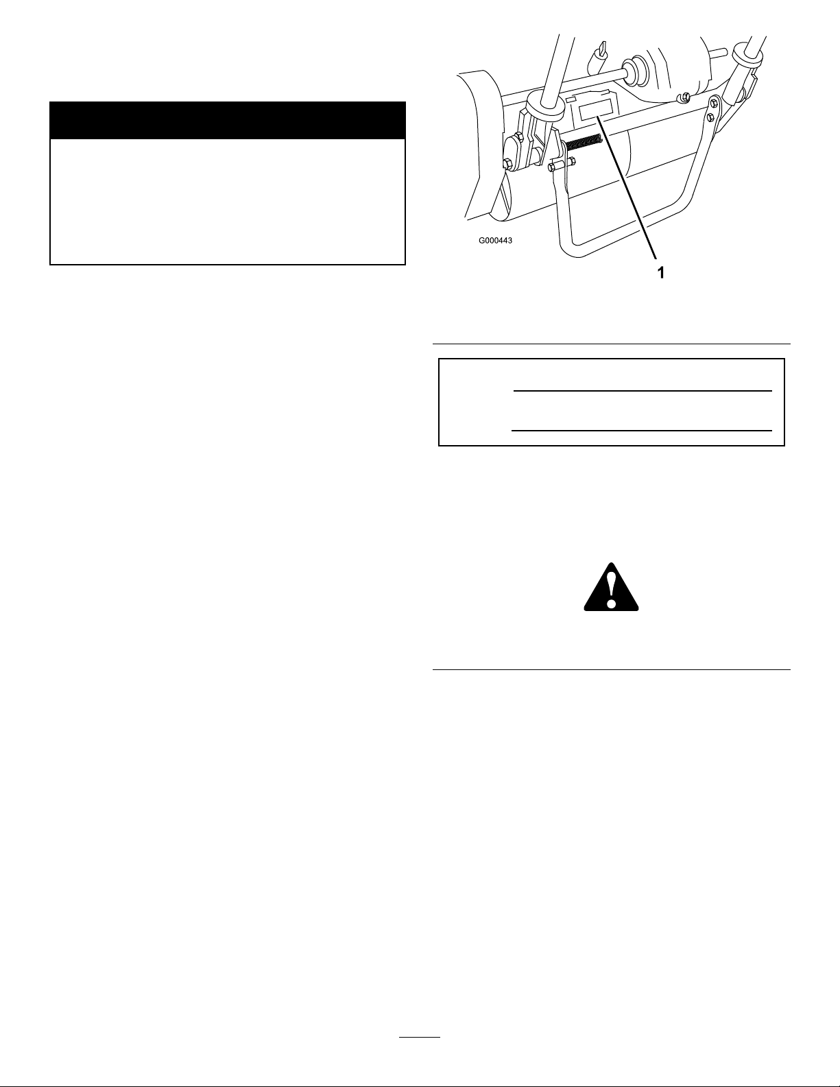
Figure1
1.Locationofthemodelandserialnumbers-Tractionunit
ModelNo.
SerialNo.
Thismanualidentiespotentialhazardsandhas
safetymessagesidentiedbythesafetyalertsymbol
(Figure2),whichsignalsahazardthatmaycauseserious
injuryordeathifyoudonotfollowtherecommended
precautions.
Figure2
1.Safetyalertsymbol.
Thismanualusestwootherwordstohighlight
information.Importantcallsattentiontospecial
mechanicalinformationandNoteemphasizesgeneral
informationworthyofspecialattention.
Wheneveryouneedservice,genuineToroparts,or
additionalinformation,contactanAuthorizedService
DealerorToroCustomerServiceandhavethemodel
andserialnumbersofyourproductready .
Figure1
identiesthelocationofthemodelandserialnumbers
ontheproduct.Writethenumbersinthespace
provided.
©2011—TheToro®Company
8111LyndaleAvenueSouth
Bloomington,MN55420
Contactusatwww.Toro.com.
2
PrintedintheUSA.
AllRightsReserved
Page 3

Contents
Introduction.................................................................2
Safety...........................................................................4
SafeOperatingPractices.......................................4
ToroMowerSafety...............................................5
SoundPowerLevel-Flex18..................................6
SoundPressureLevel-Flex18...............................6
VibrationLevel-Flex18.......................................6
SoundPowerLevel-Flex21..................................6
SoundPressureLevel-Flex21...............................7
VibrationLevel-Flex21........................................7
SafetyandInstructionalDecals.............................7
Setup............................................................................9
1InstallingtheCuttingUnittotheTraction
Unit................................................................10
2InstallingtheHandle........................................11
3InstallingtheKickstandforFlex18Mowers
Only...............................................................11
4AdjustingtheHandle.......................................12
5InstallingtheTransportWheels........................12
6CheckingFluidLevels......................................13
7InstallingtheGrassBasket...............................13
ProductOverview......................................................15
Controls.............................................................15
Specications.....................................................16
Attachments/Accessories...................................16
Operation...................................................................17
ThinkSafetyFirst...............................................17
CheckingtheEngineOilLevel............................17
FillingtheFuelTank...........................................17
CheckingtheInterlockSwitchOperation............18
StartingandStoppingtheEngine........................18
TransportOperation..........................................18
PreparingtoMow...............................................19
MowingOperation.............................................19
Maintenance...............................................................21
RecommendedMaintenanceSchedule(s)................21
DailyMaintenanceChecklist...............................22
EngineMaintenance...............................................23
EngineOil..........................................................23
ServicingtheAirCleaner....................................24
ReplacingtheSparkPlug....................................24
FuelSystemMaintenance.......................................25
CleaningtheFuelFilter.......................................25
ElectricalSystemMaintenance................................26
ServicingtheInterlockSwitch............................26
DriveSystemMaintenance.....................................26
CheckingtheTransmissionFluidLevel...............26
ChangingtheTransmissionFluid........................27
BrakeMaintenance.................................................27
AdjustingtheService/ParkingBrake...................27
BeltMaintenance....................................................28
AdjustingtheBelts.............................................28
ControlsSystemMaintenance.................................31
AdjustingtheTractionControl...........................31
AdjustingtheReelControl..................................31
Storage.......................................................................32
3
Page 4

Safety
–Refueloutdoorsonlyanddonotsmokewhile
refuelling.
ThismachinemeetsorexceedsCENstandard
EN836:1997,ISOstandard5395:1990,andANSI
B71.4-2004specicationsineffectatthetimeof
productionwhentheOperatorPresenceKit,PartNo.
105-5333isinstalled.
Improperuseormaintenancebytheoperatororowner
canresultininjury.Toreducethepotentialforinjury,
complywiththesesafetyinstructionsandalwayspay
attentiontothesafetyalert
CAUTION,WARNING,orDANGER-“personalsafety
instruction."Failuretocomplywiththeinstructionmay
resultinpersonalinjuryordeath.
symbol,whichmeans
SafeOperatingPractices
ThefollowinginstructionsarefromtheCENstandard
EN836:1997,ISOstandard5395:1990,andANSI
B71.4-2004.
Training
•ReadtheOperator’sManualandothertraining
materialcarefully .Befamiliarwiththecontrols,
safetysigns,andtheproperuseoftheequipment.
•Neverallowchildrenorpeopleunfamiliarwiththese
instructionstouseorservicethemower.Local
regulationsmayrestricttheageoftheoperator.
•Nevermowwhilepeople,especiallychildren,orpets
arenearby .
•Keepinmindthattheoperatororuserisresponsible
foraccidentsorhazardsoccurringtootherpeopleor
theirproperty.
•Theowner/usercanpreventandisresponsiblefor
accidentsorinjuriesoccurringtohimselforherself,
otherpeople,orproperty.
Preparation
•Whilemowing,alwayswearsubstantialfootwear,
longtrousers,hardhat,safetyglasses,andear
protection.Longhair,looseclothing,orjewelrymay
gettangledinmovingparts.Donotoperatethe
equipmentwhenbarefootorwearingopensandals.
•Thoroughlyinspecttheareawheretheequipment
istobeusedandremoveallobjectswhichmaybe
thrownbythemachine.
•Warning-Fuelishighlyammable.Takethe
followingprecautions:
–Addfuelbeforestartingtheengine.Never
removethecapofthefueltankoraddfuelwhile
theengineisrunningorwhentheengineishot.
–Iffuelisspilled,donotattempttostartthe
enginebutmovethemachineawayfromthe
areaofspillageandavoidcreatinganysourceof
ignitionuntilfuelvaporshavedissipated.
–Replaceallfueltanksandcontainercapssecurely.
•Replacefaultysilencers.
•Evaluatetheterraintodeterminewhataccessories
andattachmentsareneededtoproperlyand
safelyperformthejob.Onlyuseaccessoriesand
attachmentsapprovedbythemanufacturer.
•Checkthatoperator’spresencecontrols,safety
switchesandshieldsareattachedandfunctioning
properly.Donotoperateunlesstheyarefunctioning
properly.
Operation
•Donotoperatetheengineinaconnedspacewhere
dangerouscarbonmonoxidefumescancollect.
•Mowonlyindaylightoringoodarticiallight.
•Beforeattemptingtostarttheengine,disengageall
bladeattachmentclutches,shiftintoneutral,and
engagetheparkingbrake.
•Stayalertforholesintheterrainandotherhidden
hazards.
•Watchoutfortrafcwhencrossingornearroadways.
•Stopthebladesrotatingbeforecrossingsurfaces
otherthangrass.
•Whenusinganyattachments,neverdirectdischarge
ofmaterialtowardbystandersnorallowanyonenear
themachinewhileinoperation.
•Neveroperatethemachinewithdamagedguards,
shields,orwithoutsafetyprotectivedevicesinplace.
Besureallinterlocksareattached,adjustedproperly ,
andfunctioningproperly .
•Donotchangetheenginegovernorsettingsor
overspeedtheengine.Operatingtheengineat
excessivespeedmayincreasethehazardofpersonal
injury.
•Beforeleavingtheoperator’sposition:
–stoponlevelground;
–Storefuelincontainersspecicallydesignedfor
thispurpose.
–disengagethepowertake-offandlowerthe
attachments;
4
Page 5

–changeintoneutralandsettheparkingbrake;
–stoptheengine.
•Disengagedrivetoattachmentswhentransporting
ornotinuse.
•Stoptheengineanddisengagedrivetoattachment
–beforerefuelling;
–beforeremovingthegrasscatcher/catchers;
–beforemakingheightadjustmentunless
adjustmentcanbemadefromtheoperator’s
position.
–beforeclearingblockages;
–beforechecking,cleaningorworkingonthe
mower;
–afterstrikingaforeignobjectorifanabnormal
vibrationoccurs.Inspectthemowerfordamage
andmakerepairsbeforerestartingandoperating
theequipment.
•Reducethethrottlesettingbeforestoppingengine
and,iftheengineisprovidedwithafuelshut-off
valve,turnthevalveoffattheconclusionofmowing.
•Keephandsandfeetawayfromthecuttingunit.
•Slowdownandusecautionwhenmakingturns
andcrossingroadsandsidewalks.Stopreelsifnot
mowing.
•Keepallpartsingoodworkingconditionandall
hardwareandhydraulicttingstightened.Replaceall
wornordamagedpartsanddecals.
•Ifthefueltankhastobedrained,dothisoutdoors.
•Becarefulduringadjustmentofthemachineto
prevententrapmentofthengersbetweenmoving
bladesandxedpartsofthemachine.
•Disengagedrives,disengagethecuttingunit,set
parkingbrake,stopengineanddisconnectsparkplug
wire.Waitforallmovementtostopbeforeadjusting,
cleaningorrepairing.
•Cleangrassanddebrisfromcuttingunit,drives,
mufers,andenginetohelppreventres.Cleanup
oilorfuelspillage.
•Carefullyreleasepressurefromcomponentswith
storedenergy.
•Disconnectbatteryandremovesparkplugwire
beforemakinganyrepairs.Disconnectthenegative
terminalrstandthepositivelast.Reconnect
positiverstandnegativelast.
•Usecarewhencheckingthereel.W earglovesand
usecautionwhenservicingthem.
•Keephandsandfeetawayfrommovingparts.If
possible,donotmakeadjustmentswiththeengine
running.
•Donotoperatethemowerundertheinuenceof
alcoholordrugs
•Lightningcancausesevereinjuryordeath.If
lightningisseenorthunderisheardinthearea,do
notoperatethemachine;seekshelter.
•Usecarewhenloadingorunloadingthemachine
intoatrailerortruck
•Usecarewhenapproachingblindcorners,shrubs,
trees,orotherobjectsthatmayobscurevision.
MaintenanceandStorage
•Keepallnuts,boltsandscrewstighttobesurethe
equipmentisinsafeworkingcondition.
•Neverstoretheequipmentwithfuelinthetank
insideabuildingwherefumesmayreachanopen
ameorspark.
•Allowtheenginetocoolbeforestoringinany
enclosure.
•Toreducetherehazard,keeptheengine,silencer,
batterycompartmentandfuelstorageareafreeof
grass,leaves,orexcessivegrease.
ToroMowerSafety
Thefollowinglistcontainssafetyinformationspecic
toToroproductsorothersafetyinformationthatyou
mustknowthatisnotincludedintheCEN,ISO ,or
ANSIstandard.
Thisproductiscapableofamputatinghandsand
feetandthrowingobjects.Alwaysfollowallsafety
instructionstoavoidseriousinjuryordeath.
Useofthisproductforpurposesotherthanitsintended
usecouldprovedangeroustouserandbystanders.
•Knowhowtostoptheenginequickly.
•Donotoperatethemachinewhilewearingtennis
shoesorsneakers.
•Wearingsafetyshoesandlongpantsisadvisableand
requiredbysomelocalordinancesandinsurance
regulations.
•Handlegasolinecarefully.Wipeupanyspills.
•Checkthesafetyinterlockswitchesdailyforproper
operation.Ifaswitchshouldfail,replacetheswitch
beforeoperatingthemachine.
•Checkthegrasscatcherfrequentlyforwearor
deterioration.
•Alwaysstandbehindthehandlewhenstartingand
operatingthemachine.
5
Page 6

•Tostartandstoptheengine:
–Openfuelshut-offvalve.
–Verifythatthetractionandreeldrivecontrol
leversonhandleareinNeutralposition.
–Movetheon/offswitch,locatedonthecontrol
panel,toONposition,setchoketofullchoke
position(coldstart)andthrottletohalfthrottle.
–Pullstartercordtostartengine.
–MovethrottletoSlowandon/offswitchtoOff
positiontostopengine.
•Totransportmowerfromoneareatoanother:
–Installtransportwheels.
–Disengagereeldrive.
–Startengine.
–Pressdownonhandletoraisefrontofmower
andengagetractiondrive.
•Beforebeginningmowingoperation:
–Disengagetractiondrive.
–Stopengine.
–Removetransportwheels.
–Startengine
–Engagereeldrive.
•Usingthemachinedemandsattention.T oprevent
lossofcontrol:
–Donotdriveclosetosandtraps,ditches,creeks,
orotherhazards.
–Reducespeedwhenmakingsharpturns.Avoid
suddenstopsandstarts.
–Whennearorcrossingroads,alwaysyieldthe
right-of-way.
•Thegrassbasketmustbeinplace,duringthe
mowingoperation,formaximumsafety.Shutthe
engineoffbeforeemptyingthebasket.
•Donottouchtheengine,mufer,orexhaustpipe
whiletheengineisrunningorsoonafterithas
stoppedbecausetheseareascouldbehotenough
tocauseburns.
•Whenapersonorpetappearsunexpectedlyin
ornearthemowingarea,stopmowing.Careless
operation,combinedwithterrainangles,ricochets,
orimproperlypositionedguardscanleadtothrown
objectinjuries.Donotresumemowinguntilthe
areaiscleared.
MaintenanceandStorage
•Checkallfuellinesfortightnessandwearona
regularbasis.Tightenorrepairthemasneeded.
•Iftheenginemustberunningtoperforma
maintenanceadjustment,keephands,feet,clothing,
andanypartsofthebodyawayfromthecuttingunit,
attachmentsandanymovingparts.Keepeveryone
away.
•Toensuresafetyandaccuracy,haveanAuthorized
ToroDistributorcheckthemaximumenginespeed
withatachometer.Maximumgovernedenginespeed
shouldbe3600RPM.
•Ifmajorrepairsareeverneededorifassistanceis
desired,contactanAuthorizedToroDistributor.
•UseonlyToro-approvedattachmentsand
replacementparts.Thewarrantymaybevoidedif
usedwithunapprovedattachments.
SoundPowerLevel-Flex18
Thisunithasaguaranteedsoundpowerlevelof96dBA,
whichincludesanUncertaintyValue(K)of1dBA.
Soundpowerlevelwasdeterminedaccordingtothe
proceduresoutlinedinEN11094.
SoundPressureLevel-Flex18
Thisunithasasoundpressurelevelattheoperator’s
earof84dBA,whichincludesanUncertaintyValue(K)
of1dBA.
Soundpressurelevelwasdeterminedaccordingtothe
proceduresoutlinedinEN836.
VibrationLevel-Flex18
Hand-Arm
Measuredvibrationlevelforrighthand=2.36m/s
Measuredvibrationlevelforlefthand=2.47m/s
UncertaintyValue(K)=0.5m/s
Measuredvaluesweredeterminedaccordingtothe
proceduresoutlinedinEN836.
2
2
SoundPowerLevel-Flex21
Thisunithasaguaranteedsoundpowerlevelof97dBA,
whichincludesanUncertaintyValue(K)of1dBA.
Soundpowerlevelwasdeterminedaccordingtothe
proceduresoutlinedinEN11094.
2
6
Page 7

SoundPressureLevel-Flex21
VibrationLevel-Flex21
Thisunithasasoundpressurelevelattheoperator’s
earof92dBA,whichincludesanUncertaintyValue(K)
of1dBA.
Soundpressurelevelwasdeterminedaccordingtothe
proceduresoutlinedinEN836.
SafetyandInstructionalDecals
Safetydecalsandinstructionsareeasilyvisibletotheoperatorandarelocatednearanyareaof
potentialdanger.Replaceanydecalthatisdamagedorlost.
Hand-Arm
Measuredvibrationlevelforrighthand=2.36m/s
Measuredvibrationlevelforlefthand=2.47m/s
UncertaintyValue(K)=0.5m/s
2
Measuredvaluesweredeterminedaccordingtothe
proceduresoutlinedinEN836.
115-1615
1.Warning—donottouchthehotsurface.
2
2
115-1613
1.Warning—readthe
Operator’sManual.
2.Warning—remove
thesparkplugwire
beforeperformingany
maintenanceonthe
machine.
1.Entanglementhazard—stayawayfrommovingparts.
3.Thrownobject
hazard—keepbystanders
asafedistancefromthe
machine.
4.Cutting,dismemberment
hazardofhandor
foot—stayawayfrom
movingparts.
93-9356
1.Fast
2.Continuousvariable
setting
93-6085
3.Slow
1.Engine—stop2.Engine—run
7
112-9408
Page 8
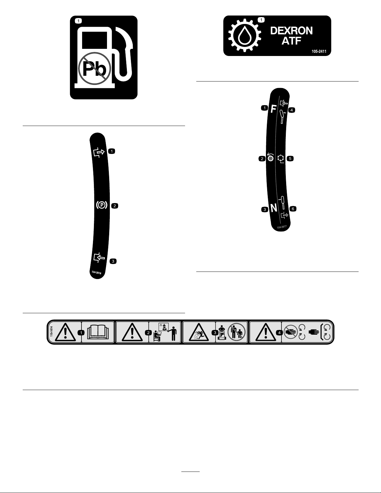
1.Useunleadedgasoline.
105-2411
1.Transmissionoil
93-9886
104-2617
1.Tractiondrive4.Forward
2.Reeldrive5.Leverengaged
3.Neutral6.Leverdisengaged
104-2618
1.Parkingbrake3.Engage
2.Disengage
115-1614
1.Warning—readtheOperator’sManual.3.Thrownobjecthazard—keepbystandersasafedistancefrom
2.Warning—donotoperatethemachineunlessyouaretrained.
themachine.
4.Warning—stayawayfrommovingparts;keepallguardsin
place.
8
Page 9

Setup
LooseParts
Usethechartbelowtoverifythatallpartshavebeenshipped.
ProcedureDescription
1
2
3
4
5
6
7
Qty.
Bolt,M10x25mm2Installthecuttingunittothetractionunit
Handle1Installthehandle.
Kickstandassembly1
Spring
Smallspacer
Largespacer1
Largebolt(M8–1.25x100)
Smallbolt(M8–1.25x030)
Locknut(M8x1.25)
Washer(M8)
Nopartsrequired
Transportwheels(OptionalTransport
WheelKit,Model04123)
Nopartsrequired
Grassbasket
1
1
InstallthekickstandforFlex18Mowers
1
1
2
2
–
2Installthetransportwheels.
–
1Installthegrassbasket.
Only.
Adjustthehandle.
Checktheengineoilandtransmission
uidlevels
Use
MediaandAdditionalParts
Description
Operator’sManual
EngineOperator’sManual
PartsCatalog
OperatorTrainingMaterial
CerticateofCompliance
Qty.
Use
1
1
1
1
1
Readorviewbeforeoperatingthemachine
9
Page 10
Note:Determinetheleftandrightsidesofthemachine
fromthenormaloperatingposition.
1
InstallingtheCuttingUnitto
theTractionUnit
Partsneededforthisprocedure:
2Bolt,M10x25mm
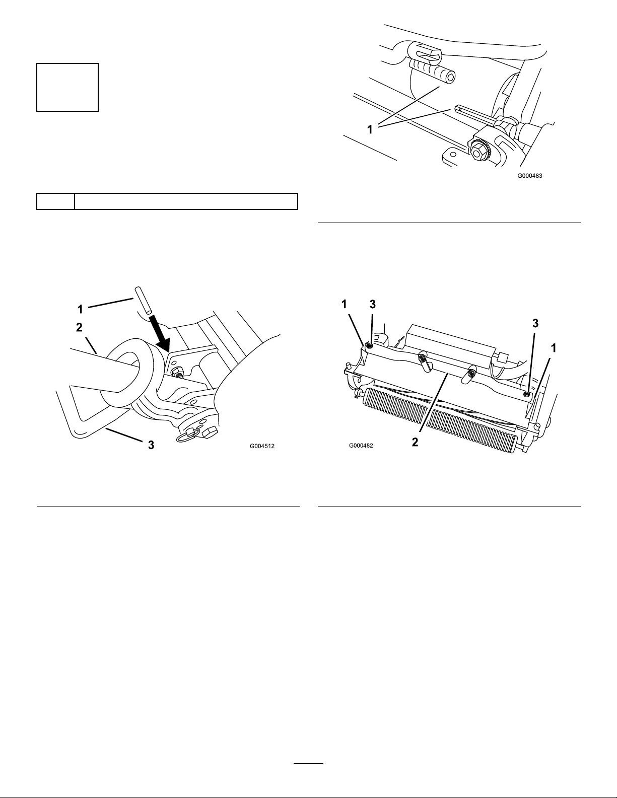
1.Placethemoweronitsdrumsonalevelsurface.
2.Lowerkickstand.Inserta1/4"dia.pinorequivalent
intoframeholeabovekickstandmountingbolt
(Figure3).
Figure3
1.1/4"Pin
2.Handle
3.Kickstand
Figure4
1.Transmissioncoupling
4.Rotatethetractionunitframe(Figure5)forward
untilitengagesthecuttingunitpivotarms.
5.Securethetractionunitframetothecuttingunit
pivotarmswith(2)M10x25mmbolts(Figure5)
Figure5
1.Cuttingunitpivotarms
2.Tractionunitframe
3.Bolts
3.Pushthecuttingunitunderthetractionunitand
thentothelefttoengagethetransmissioncoupling
(Figure4).
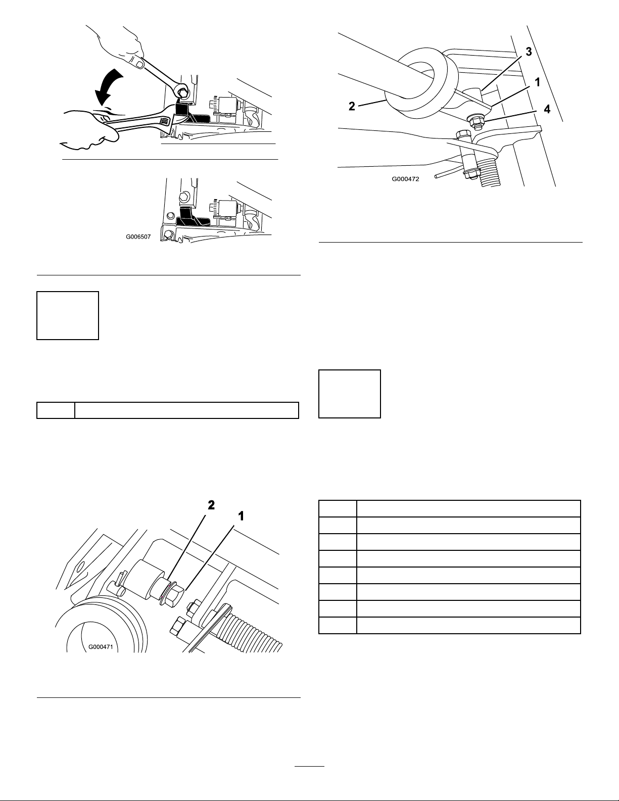
Note:Whentighteningthepivotarmmounting
fasteners,useanadjustableendwrenchtoholdthe
pivotarmparalleltothesideplate(Figure6)
10
Page 11
1.Lefthandleend
2.Supportarm
Figure8
3.Pivotpin
4.Locknut
Figure6
2
InstallingtheHandle
Partsneededforthisprocedure:
1Handle
Procedure
1.Removetheangelocknutfromtheboltandpivot
pinoneachsideofthemower(
Figure7).
3.Squeezethehandleendsinwardandinstallthemon
thestepofthepivotpin(
4.Securethehandletotheboltandpivotpinwiththe
angelocknut(Figure8).
5.Locatecabletielooselysecuringthrottlecableto
wireharness.Positioncabletieapproximatelyone
inchbehindtransmissionandtightencabletie.
Figure8).
3
InstallingtheKickstandfor
Flex18MowersOnly
Partsneededforthisprocedure:
1Kickstandassembly
1
Spring
1
Smallspacer
1Largespacer
1
Largebolt(M8–1.25x100)
1
Smallbolt(M8–1.25x030)
2
Locknut(M8x1.25)
2
Washer(M8)
Figure7
1.Flangelocknut2.Pivotpin
2.Insertthehandleendsthroughtheslotsinthehandle
supportarms(Figure8).
Procedure
1.Positionthekickstandbetweenthetabsontherear
oftheframe.
2.Installawasher(M8)ontothesmallbolt(M8–1.25
x030).Installtherightsideofthekickstandtothe
11
Page 12

framewiththeboltandwasher,thesmallspacer,
andlocknut(M8–1.25)(Figure9).Ensurethebolt
isinstalledfromtheinsideoftheframeasshown
Figure9.
in
3.Installawasher(M8)ontothelargebolt(M8–1.25x
100).
4.Installthespacerintothespringandinstallthelarge
bolt(M8–1.25x100)intothespacer.
Important:Wheninstallingthespring,place
oneendofthespringundertherearframe
Figure9).
(
5.Installtheleftsideofthekickstandtotheframe
withtheboltandwasher,thelargespacerandspring,
andlocknut(M8–1.25)(Figure9).Ensurethebolt
isinstalledfromtheinsideoftheframeasshown
Figure9.
in
Figure10
1.Spring
2.Springendunderthe
frame
3.Nutrunner
4.Movethespringendunder
thekickstandspacer.
4
AdjustingtheHandle
NoPartsRequired
Procedure
1.Removehairpincottersfromringpinsoneachside
ofmower(Figure11).
Figure9
1.Lefthandleend5.Largebolt(M8–1.25x
2.Locknut(M8–1.25)6.Spring
3.Smallspacer
4.Washer(M8)8.Ssmallbolt(M8–1.25x
100)
7.Largespacer
030)
6.Placeanutrunnerovertheendofthespringpointing
towardstherearandmovetheendofthespringover
andunderthekickstandspacer(Figure10).
Figure11
1.Ringpins
2.Whilesupportinghandle,removeringpinsfrom
eachsideandraiseorlowerhandletodesired
operatingposition(Figure11).
3.Reinstallringpinsandhairpincotters.
12
Page 13

5
InstallingtheTransport
Wheels
Partsneededforthisprocedure:
Transportwheels(OptionalTransportWheelKit,
2
Model04123)
Procedure
1.Pushkickstanddownwithfootandpullupon
handlesupportuntilkickstandhasrotatedforward,
overcenter(Figure12).
Figure13
1.Lockingclip
3.Rotatewheelbackandforthuntilitslidescompletely
ontoaxleandlockingclipissecuredingrooveon
axleshaft.
Figure12
1.Kickstand
2.Presswheellockingcliptowardthecenterofwheel
andslidewheelontohexshaft(Figure13).
4.Repeatprocedureonoppositesideofmachine.
5.Inatethetiresto12-15psi.
6.Carefullyliftuponhandlesupporttoreleasekick
stand.
6
CheckingFluidLevels
NoPartsRequired
Procedure
1.Checktheengineoillevel,refertoCheckingthe
EngineOilLevel.
2.Checkthetransmissionuidlevel,refertoChecking
theTransmissionFluidLevel.
13
Page 14

7
InstallingtheGrassBasket
Partsneededforthisprocedure:
1
Grassbasket
Procedure
Graspbasketbytoplipandslidebasketframeintothe
receivers(Figure14).
1.Grassbasket
Figure14
2.Basketreceivers
14
Page 15

ProductOverview
G009976
1
2
3
4
5
Figure15
1.Handle
2.Controlpanel6.Grassbasket
3.Engine7.Fueltank
4.Transportwheels
Controls
5.Cuttingunit
TractionandReelDriveEngagement
Lever
Thetractionandreeldriveengagementlever(Figure16)
islocatedonfrontrightsideofcontrolpanel.Traction
leverhastwopositions:NeutralandForward.Pushing
leverforwardengagestractiondrive.
Thereeldriveleverhastwopositions:Engageand
Disengage.Movetopoflevertothelefttoengagereel
orbacktoneutraltodisengagereel.
Service/ParkingBrake
Theservice/parkingbrake(Figure16)islocatedonleft
frontsideofcontrolpanel.Pullingtheleverbackover
centerwillsettheparkingbrake.Brakemustbereleased
beforetractiondriveisengaged.
On/OffSwitch
Theon/offswitch(Figure16)islocatedontopof
controlpanel.MoveswitchtoOnpositiontostart
engineandOfftostopengine.
HourMeter
Thehourmeter(Figure16),locatedontopofthe
controlpanel,indicatesthetotalhoursofmachine
operation.
OperatorPresenceControl
Figure16
1.Throttlecontrol
2.Traction&reeldrive
engagementlever
3.Service/parkingbrake
4.On/offswitch
5.Hourmeter
ThrottleControl
Thethrottlecontrol(Figure16)islocatedonrearright
sideofcontrolpanel.Leverconnectstoandoperates
throttlelinkagetocarburetor.Enginespeedcanbe
variedfrom2400RPMto3600RPM.
Theoptionaloperatorpresencecontrolmustbeengaged
beforeengagingthetractionleverortheenginewillstop.
ChokeLever
Thechokelever(Figure17)islocatedonleftfrontof
engine.Leverhastwopositions:RunandChoke.Move
thechokelevertothehalf-openpositionwhenstarting
acoldengine.AfterenginestartsmovelevertoRun
position.
1.Chokelever2.Fuelshut-offvalve
Figure17
15
Page 16

FuelShut-OffValve
G009975
1
Kickstand
Thefuelshut-offvalve(Figure17)islocatedonleft
frontofengine.Valvehastwopositions:Closedand
Open.Movelevertoclosedpositionwhenstoring
ortransportingmachine.Openvalvebeforestarting
engine.
RecoilStarter
Pullrecoilstarterhandle(Figure18)tostartengine.
Thekickstand(Figure19)ismountedtorearofmachine
andisusedtoraiserearofmachineforinstallationor
removaloftransportwheels.
Figure19
1.Kickstand
Specications
Attachments/Accessories
Figure18
1.Recoilstarter
Flex21Flex18
Width
Height
Lengthwithbasket
Netweight
Widthofcut21inches(53.3cm)18inches(45.7cm)
Heightofcut1/16to19/64inches(1.5to7.5mm)with
Clipfrequency11blade(standard):.14inch11blade(standard):.14inch
35-1/2inches(90.1cm)32inches(81.3cm)
41–1/4inches(104.8cm)41–1/2inches(105.4cm)
61–1/2inches(156.2cm)61inches(155cm)
Model04024–185lb(84kg)Model04019–175lb(79kg)
Model04202–82lb(37kg)Model04206–82lb(37kg)
Model04025–185lb(84kg)Model04207–89lb(40kg)
Model04208–89lb(40kg)
Micro-Cutbedknife
1/16to19/64inches(1.5to7.5mm)withMicro-Cut
bedknife
AselectionofToroapprovedattachmentsand
accessoriesareavailableforusewiththemachineto
enhanceandexpanditscapabilities.Contactyour
AuthorizedServiceDealerorDistributororgoto
www.Toro.comforalistofallapprovedattachments
andaccessories.
16
Page 17

Operation
g014638
Note:Determinetheleftandrightsidesofthe
machinefromthenormaloperatingposition.
DANGER
Incertainconditions,gasolineisextremely
ammableandhighlyexplosive.Areorexplosion
fromgasolinecanburnyouandothersandcan
damageproperty.
ThinkSafetyFirst
Pleasecarefullyreadallofthesafetyinstructionsand
decalsinthesafetysection.Knowingthisinformation
couldhelpyouorbystandersavoidinjury.
CheckingtheEngineOilLevel
Checktheengineoillevelbeforeeachuseorevery8
operatinghours,refertoCheckingtheEngineOilLevel.
FillingtheFuelTank
Important:Neverusemethanol,gasoline
containingmethanol,gasoholcontainingmore
than10%ethanol,gasolineadditives,premium
gasoline,orwhitegasbecausethefuelsystem
couldbedamaged.Donotmixoilwithgasoline.
•Fillthefueltankoutdoors,inanopenarea,
whentheengineiscold.Wipeupanygasoline
thatspills.
•Donotllthefueltankcompletelyfull.Add
gasolinetothefueltankuntilthelevelis1inch
(25mm)belowthebottomofthellerneck.
Thisemptyspaceinthetankallowsgasoline
toexpand.
•Neversmokewhenhandlinggasoline,andstay
awayfromanopenameorwheregasoline
fumesmaybeignitedbyaspark.
•Storegasolineinanapprovedcontainerand
keepitoutofthereachofchildren.Neverbuy
morethana30-daysupplyofgasoline.
•Alwaysplacegasolinecontainersontheground
awayfromyourvehiclebeforelling.
•Donotllgasolinecontainersinsideavehicle
oronatruckortrailerbedbecauseinterior
carpetsorplastictruckbedlinersmayinsulate
thecontainerandslowthelossofanystatic
charge.
Figure20
1.Fueltankcap
WARNING
Gasolineisharmfulorfatalifswallowed.
Long-termexposuretovaporscancauseserious
injuryandillness.
•Avoidprolongedbreathingofvapors.
•Keepfaceawayfromnozzleandgastankor
conditioneropening .
•Keepgasawayfromeyesandskin.
•Whenpractical,removegas-powered
equipmentfromthetruckortrailerandrefuel
theequipmentwithitswheelsontheground.
•Ifthisisnotpossible,thenrefuelsuch
equipmentonatruckortrailerfromaportable
container,ratherthanfromagasolinedispenser
nozzle.
•Ifagasolinedispensernozzlemustbeused,
keepthenozzleincontactwiththerimofthe
fueltankorcontaineropeningatalltimesuntil
fuelingiscomplete.
1.Cleanaroundfueltankcapandremovecapfrom
tank(Figure20).Usingunleadedgasoline,llfuel
tanknohigherthantobottomoflterscreen.Do
notoverll.
2.Installfueltankcapandwipeupanyspilledgasoline.
17
Page 18

CheckingtheInterlockSwitch
Operation
5.Iftheenginedoesnotshutoff,theinterlock
switchneedsservice.Correcttheproblembefore
operating.
CAUTION
Ifsafetyinterlockswitchesaredisconnectedor
damagedthemachinecouldoperateunexpectedly
causingpersonalinjury.
•Donottamperwiththeinterlockswitches.
•Checktheoperationoftheinterlockswitches
dailyandreplaceanydamagedswitchesbefore
operatingthemachine.
TractionInterlockSwitch
1.Pushkickstanddownwithfootandpullupon
handlesupportuntilkickstandhasrotatedforward,
overcenter(Figure21).
6.Carefullyliftuponhandletoreleasekickstand.
StartingandStoppingthe
Engine
Note:Forillustrationsanddescriptionsofthecontrols
referencedinthissection,refertotheControlws
sectioninOperation.
StartingtheEngine
Note:Makesuresparkplugwireisinstalledonspark
plug.
1.Makesuretractionandreeldriveleversarein
Disengagedposition.
Note:Enginewillnotstartiftractionleverisin
theengagedposition.
2.Openthefuelshut-offvalveontheengine.
3.Movetheon/offswitchtotheOnposition.
4.MovethethrottlecontroltotheFastposition.
Figure21
1.Kickstand
2.PlacetractionleverintoEngagepositionandengine
controlsinstartingposition.
3.Attempttostartengine.Engineshouldnotstart.
Ifenginestarts,theinterlockswitchneedsservice.
Correcttheproblembeforeoperating.Referto
ServicingInterlockSwitch.
4.Carefullyliftuponhandletoreleasekickstand.
BrakeInterlockSwitch
1.Pushkickstanddownwithfootandpullupon
handlesupportuntilkickstandhasrotatedforward,
overcenter(Figure21).
5.Movethechokelevertothehalf-openposition
whenstartingacoldengine.Thechokemaynotbe
requiredwhenstartingawarmengine.
6.Pulltherecoilstarterhandleoutuntilpositive
engagementresults,thenpullitvigorouslytostart
theengine.Openthechokeasenginewarmsup.
Important:Donotpullrecoilropetoitslimit
orletgoofstarterhandlewhenropeispulled
outbecauseropemaybreakorrecoilassembly
maybedamaged.
StoppingtheEngine
1.Movethetractionandreeldrivecontrolstothe
Disengagedposition,thethrottlecontroltoSlow,
andtheon/offswitchtoOff.
2.Pullthemoldedsparkplugwireoffofthespark
plugtopreventthepossibilityofaccidentalstarting
beforestoringmachine.
3.Closethefuelshut-offvalvebeforestoringor
transportingmowerinavehicle.
2.Starttheengine.
3.MovethebrakelevertotheEngageposition.
4.MovetractionleverintoEngageposition,engine
mustshutoff.
TransportOperation
Note:Donotrunthemowerenginewhiletransporting
itinatransporttrailerbecausedamagecanoccurto
themower.
18
Page 19

Ifoptionaltransportwheelsarenotgoingtobe
installed,proceedtostep4.
1.Pushkickstanddownwithfootandpullupon
handlesupportuntilkickstandhasrotatedforward,
overcenter.
2.Installthetransportwheels.
3.Toreleasekickstand,pulluponhandleandlower
rearofmowerontotransportwheels.
4.Ensuretractionandreeldrivecontrolsarein
Disengagepositionandstartengine.
5.SetthrottlecontroltoSlow ,tipfrontofmachineup
graduallyengagetractiondriveandslowlyincrease
enginespeed.
6.Adjustthrottletooperatemoweratdesiredground
speedandtransportmowertodesireddestination.
PreparingtoMow
1.ReturntractioncontrollevertoDisengage,throttle
toSlowandstopengine.
2.Pushkickstanddownwithfootandpullupon
handlesupportuntilkickstandhasrotatedforward,
overcenter.
byraisingthecuttingreel(pushingthehandledown)
andturningonthetractiondrum.Mowingshouldbe
doneatanormalwalkingpace.Fastspeedssavesvery
littletimeandwillresultinaninferiormowingjob.
Toassistinmaintainingastraightlineacrossthegreen
andtokeepthemachineanequaldistancefromthe
edgeofthepreviouscut,usethealignmentstripeson
thebasket(Figure22).
Figure22
1.Alignmentstripes
3.Removetransportwheels.
4.Releasekickstand.
MowingOperation
Properuseofthemachineprovidesthesmoothestturf
cuttingavailable.
Important:Grassclippingsactasalubricant
whenmowing.Excessiveoperationofthecutting
unitwiththeabsenceofgrassclippingscan
damagethecuttingunit.
PriortoMowing
Besurethemoweriscarefullyadjustedandissetevenly
onbothsidesofthereel.Impropermoweradjustment
ismagniedintheappearanceoftheclippedturf.
Removeallforeignobjectsfromturfpriortomowing.
Makesureeveryone,especiallychildrenandpets,are
clearoftheworkarea.
ControlOperation
Tooperatethecontrolswhilemowing:
1.Starttheengine,setthethrottleatreducedspeed,
pushdownonhandletoraisecuttingunit,move
tractionlevertoEngagedpositionandtransport
mowerontocollarofgreen(
2.MovetractionlevertoDisengagedpositionand
Engagereeldrivelever(
Figure23).
Figure23).
MethodofMowing
Thegreensshouldbemowedinastraightbackand
forthdirectionacrossthegreen.Avoidcircularmowing
orturningthemowerongreensareassincescufngmay
occur.Turningthemowershouldbedoneoffthegreen
19
Page 20

Figure23
1.Tractiondrive-neutral3.Tractiondrive-engaged
2.Tractiondriveneutral&
reeldriveoff
(transport)
4.Tractiondrive&reeldrive
engaged
3.MovetractionlevertoEngagedposition,increase
throttlespeeduntilthemoweristravelingatthe
desiredgroundspeed,drivethemoweroutontothe
greenarea,lowerthefrontofthemowerdownand
commenceoperation(
Figure23).
AfterMowing
1.Driveoffgreen,movereeldriveandtractioncontrol
leverstoDisengageandstoptheengine.
2.Emptythegrasscatcherofclippings,installgrass
catcherandcommencetransportoperation.
20
Page 21

Maintenance
Note:Determinetheleftandrightsidesofthemachinefromthenormaloperatingposition.
RecommendedMaintenanceSchedule(s)
MaintenanceService
Interval
Aftertherst8hours
Aftertherst25hours
Beforeeachuseordaily
Every25hours
Every50hours
Every100hours
Every800hours
Beforestorage
MaintenanceProcedure
•Changetheengineoil.
•Cleanthefuellter.
•Changethetransmissionuid.
•Checktheengineoillevel.
•Cleantheaircleaner(moreoftenindirtyordustyconditions).
•Changetheengineoil.
•Cleanthefuellter.
•Checkthetransmissionuidlevel.
•Checkthepaperairlterelementandreplaceasrequired(moreoftenindirtyor
dustyconditions).
•Checkthesparkplug.
•Changethetransmissionuid.(Or2years,whicheveroccursrst)
•Paintchippedsurfaces.
Important:Refertoyourengineoperator’smanualforadditionalmaintenanceprocedures.
21
Page 22

DailyMaintenanceChecklist
Important:Duplicatethispageforroutineuse.
Maintenance
CheckItem
Checkthe
safetyinterlock
operation.
Checktheparking
brakeoperation.
Checkthatpivot
jointsoperate
freely.
Checkthefuel
level.
Checktheengine
oillevel.
Checktheair
lter.
Cleantheengine
coolingns.
Checkforunusual
enginenoises.
Checkforunusual
operatingnoises.
Checkthe
reel-to-bedknife
adjustment.
Checkthe
height-of-cut
adjustment.
Touchup
damagedpaint.
Fortheweekof:
Mon.Tues.Wed.Thurs.Fri.
Sat.Sun.
NotationforAreasofConcern
Inspectionperformedby:
ItemDate
Information
22
Page 23

EngineMaintenance
EngineOil
Thecrankcasemustbelledwithapproximately20
uidouncesofproperviscosityoilbeforestaring.The
engineusesanyhigh-qualityoilhavingtheAmerican
PetroleumInstitute-APl-“serviceclassication"SF,
SG,SHorSJ .Oilviscosity-weight-mustbeselected
accordingtoambienttemperature.Figure24illustrates
thetemperature/viscosityrecommendations.
Figure25
1.Oillevelgauge
2.Removeoillevelgaugebyrotatingit
counterclockwise.
2.Drainplug
Figure24
Note:Usingmulti-gradeoils(5W-20,10W-30,and
10W-40)willincreaseoilconsumption.Checktheoil
levelmorefrequentlywhenusingthem.
CheckingtheEngineOilLevel
ServiceInterval:Beforeeachuseordaily
Note:Thebesttimetochecktheengineoiliswhenthe
engineiscoolbeforeithasbeenstartedfortheday.Ifit
hasalreadybeenrun,allowtheoiltodrainbackdown
tothesumpforatleast10minutesbeforechecking.If
theoillevelisatorbelowthe“L”markonthedipstick,
addoiltobringtheoilleveltothe“H”mark.DONOT
OVERFILL.Iftheoillevelisbetweenthe“H”and“L”
marks,nooiladditionisrequired.
1.Removethetransportwheels(ifinstalled),position
themowersotheengineislevelandcleanaroundoil
levelgauge(
Figure25).
3.Wipeoillevelgaugecleanandinsertitintoller
port.Donotscrewintoport.Thenremoveand
checklevelofoil.Iflevelislow,addonlyenough
oiltoraiseleveluntilitisbetweenthe“H”and“L”
marksonthegauge(
oil.Donotoverll.
4.Reinstalloillevelgaugeandwipeupanyspilledoil.
Figure26).Rechecklevelof
Figure26
ChangingtheEngineOil
ServiceInterval:Aftertherst8hours
Every50hours
1.Startandrunengineforafewminutestowarmthe
engineoil.
2.Placeadrainpanatrearofmachineunderdrainplug
(Figure25).Removedrainplug.
23
Page 24

3.Pushdownonhandletotipmowerandengine
backward,allowingalloiltorunintodrainpan.
4.Installdrainplugandrellcrankcasewiththe
speciedoil;refertoCheckingtheOilLevel.
ServicingtheAirCleaner
ServiceInterval:Every25hours
Every100hours
1.Makesurewireisoffsparkplug.
2.Removewingnutssecuringaircleanercovertoair
cleanerandremovecover.Cleancoverthoroughly
Figure27).
(
Figure27
1.Aircleanercover
Figure28
1.Foamelement2.Paperelement
4.Whenservicingfoamelement,checkconditionof
paperelement.Replaceasrequired.
Note:Donotusecompressedairtocleanthepaper
element.
5.Installfoamelement,paperelement,andaircleaner
cover.
Important:Donotoperatetheenginewithout
theaircleanerelementbecauseextremeengine
wearanddamagewilllikelyresult.
ReplacingtheSparkPlug
ServiceInterval:Every100hours
UseanNGKBPR5ESsparkplugorequivalent.Correct
airgapis0.028-0.032inch.
3.Iffoamelementisdirty,removeitfrompaper
element(
Figure28).Cleanthoroughly.
A.Washfoamelementinasolutionofliquidsoap
andwarmwater.Squeezetoremovedirt,butdo
nottwistbecausethefoammaytear.
B.Drybywrappinginacleanrag.Squeezeragand
foamelementtodry,butdonottwistbecause
thefoammaytear.
C.Saturateelementwithcleanengineoil.Squeeze
elementtoremoveexcessoilandtodistributeoil
thoroughly.Anoildampelementisdesirable.
1.Pullmoldedwireoffsparkplug(Figure29).
Figure29
1.Sparkplugwire
2.Cleanaroundsparkplugandremoveplugfrom
cylinderhead.
Important:Replaceacracked,fouled,ordirty
sparkplug.Donotsandblast,scrape,orclean
24
Page 25

electrodesbecauseenginedamagedcouldresult
fromgritenteringthecylinder.
3.Setairgapat0.028-0.032inch(Figure30).Install
correctlygappedsparkplugandtightenrmlyto
17ft.-lb(23N-m).
Figure30
FuelSystem
Maintenance
CleaningtheFuelFilter
ServiceInterval:Aftertherst25hours
Every50hours
1.Closefuelshutoffvalveandunscrewbowlfrom
lterbody(
1.Shut-offvalve
Figure31).
Figure31
2.Bowl
2.Cleanbowlandlterincleangasolineandinstall.
25
Page 26

ElectricalSystem
DriveSystem
Maintenance
ServicingtheInterlockSwitch
Usethefollowingprocedureiftheswitchneeds
adjustmentorreplacement.
1.Makesuretheengineisoffandtractionleveris
Disengaged.
2.Engagetractionleveruntilitcontactsneutralstop
Figure32).
(
Figure32
1.Tractionlever3.Interlockswitch
2.Neutralstop
3.Looseninterlockswitchmountingfasteners
Figure32).
(
4..032"Gap
Maintenance
CheckingtheTransmission
FluidLevel
ServiceInterval:Every50hours
Thetransmissionislledatthefactorywith
approximately94uidouncesofMobilDexronlll
automatictransmissionuid.
Note:Thesealsusedinthetransmissionareinternally
lubricatedwithgrease.Duringinitialoperationof
mower,slightweepingofgreasefromthesesealswill
occur.Wipeoffexcessgrease.
Important:UseonlyMobilDexronlllorequivalent
transmissionuids.Otheruidscouldcause
systemdamage.
1.Placethemoweronitsdrumsonalevelsurface.
2.Removethecheckplugfromtheright-handsideof
thetransmission(
Theoillevelshouldcometothebottomofthell
hole.Ifitdoesnot,removethellplugfromthetop
ofthetransmissionandaddenoughoftheproperoil
typeuntilthelevelreachesthebottomofthecheck
hole.Donotremovetheventpipe.
Figure33).
4.Placea.032"thickshimbetweenthetractionlever
andtheinterlockswitch(Figure32).
5.Tighteninterlockswitchmountingfasteners.
Recheckgap.Thetractionlevermustnotcontact
theswitch.
6.Engagetractionleverandverifythattheswitchloses
continuity.Replaceifrequired.
Figure33
1.Fillplug3.Drainplug
2.Checkplug
3.Installtheplugs.
26
Page 27

ChangingtheTransmission
Fluid
BrakeMaintenance
ServiceInterval:Aftertherst25hours
Every800hours(Or2years,
whicheveroccursrst)
Important:UseonlyMobilDexronlllorequivalent
transmissionuids.Otheruidscouldcause
systemdamage.
1.Placeadrainpanattherearofthemachine.
2.Removethedrainplugfromtherearofthe
transmission(
Figure34).
AdjustingtheService/Parking
Brake
Note:Theservice/parkingbrakeisaholdingbrakenot
astoppingbrake.Itisdesignedtoholdthemachineon
a17degreeslopewithoutmoving.
Ifservice/parkbrakeslipswhenoperated,anadjustment
isrequired.
1.Moveservice/parkingbrakelevertoOffposition.
2.Toincreasecabletension,loosenfrontcablejamnut
andtightenbackcablejamnut(
forceof11–14lb.(5-6.3kg)isrequiredtoengage
brake.Forcetobemeasuredatleverknob.Donot
overadjust,orbrakebandmaydrag.
Figure35)untila
Figure34
1.Fillplug3.Drainplug
2.Checkplug
3.Pushdownonthehandleandtipthemachineback.
Removethecheckplugfromtheright-handsideof
thetransmission(Figure34).
4.Whentheuidisdrained,installthedrainplug.
5.Placethemoweronitsdrumsonalevelsurface.
6.Removethellplugfromthetopofthetransmission
Figure34).Donotremovetheventpipe.
(
7.Fillthetransmissionwithapproximately94uid
ouncesofthepropertypeoftransmissionuiduntil
thelevelreachesthebottomofthecheckhole;refer
toCheckingtheTransmissionFluid.
8.Installthellandcheckplugs.
1.Tractioncable
Figure35
2.Service/parkingbrake
cable
27
Page 28

BeltMaintenance
AdjustingtheBelts
Makesurebeltsareproperlytensionedtoassureproper
operationofthemachineandunnecessarywear.Check
beltsfrequently .
ReelDriveBelt(Reel)
1.Removethebeltcovermountingfastenersandbelt
covertoexposebelt(Figure36).
Figure36
1.Beltcover
Figure38
1.Reeldrivebelt2.Bearinghousingmounting
nuts
B.Usinga3/8inchdrivetorquewrench,rotatethe
bearinghousingwith35-40in.-lb.(4-4.5N-m)of
torquetosetbelttension(Figure39)
2.Checktensionbydepressingbelt(Figure37)atmid
spanofpulleyswith4±1lb.offorce.Beltshould
deect3/16to5/16inch(4.8to7.9mm).Ifthe
deectionisincorrect,proceedtonextstep.
Figure37
1.Reeldrivebelt3.Drivenpulley
2.Drivepulley
3.Toadjustbelttension:
A.Loosenthebearinghousingmountingnuts
(
Figure38).
Figure39
1.Bearinghousing
2.3/8"Torquewrenchhere
C.Whileholdingthetorquewrenchsetting,tighten
thebearinghousingmountingnuts(
Donotover-tensionbelt.
D.Installbeltcover.
Figure38).
28
Page 29

ReelDriveBelt(Transmissioncoupler)
1.Removethebeltcovermountingfastenersandbelt
covertoexposebelt(Figure40).
Figure42
1.Reeldrivebelt2.Bearinghousingmounting
nuts
Figure40
1.Beltcover
2.Checktensionbydepressingbelt(Figure41)atmid
spanofpulleyswith4±1lb.offorce.Beltshould
deect3/16to5/16inch(4.8to7.9mm).Ifthe
deectionisincorrect,proceedtonextstep.
Figure41
1.Reeldrivebelt
B.Usinga3/8inchdrivetorquewrench,rotatethe
bearinghousingwith35-40in.-lb.(4-4.5N-m)of
torquetosetbelttension(
Figure43
1.Bearinghousing
Figure43).
2.3/8"Torquewrenchhere
C.Whileholdingthetorquewrenchsetting,tighten
thebearinghousingmountingnuts(Figure42).
Donotover-tensionbelt.
D.Installbeltcover.
3.Toadjustbelttension:
A.Loosenthebearinghousingmountingnuts
Figure42).
(
29
Page 30

TractionDriveBelt
1.Removebeltcovermountingfastenersandbelt
covertoexposebelt(Figure44).
Figure46
1.Tangwasher2.Idlerbracketbolt
Figure44
1.Tractiondrivebeltcover
2.Checktensionbydepressingbelt(Figure45)atmid
spanofpulleyswith4±1lbofforce.Beltshould
deect3/16to5/16inch(4.8to7.9mm).Ifthe
deectionisincorrect,proceedtonextstep.
Figure45
1.Tractiondrivebelt
B.Usinga3/8inchdrivetorquewrench,rotatethe
idlerbracketwith35-40in.-lb.oftorquetoset
thebelttension(Figure47).Whileholdingthe
torquewrenchsetting,tightentheidlerbracket
mountingbolt(Thetangwasherisinstalled
topreventthebeltfromslipping.).Donot
over-tensionthebelt.
Figure47
1.Tractiondrivebelt
2.Idlerbracket
3.3/8inchT orquewrench
here
3.Toadjustbelttension:
A.Onbacksideofsideplate,loosenthebolt
securingtheidlerbrackettothesideplate
(Figure46).
C.Installthebeltcover.
30
Page 31

ControlsSystem
Maintenance
AdjustingtheTractionControl
Iftractioncontroldoesnotengageoritslipsduring
operation,anadjustmentisrequired.
1.MovetractioncontroltoDisengagedposition.
2.Toincreasecabletension,loosenfrontcablejamnut
andtightenbackcablejamnut(
forceof10-13lbs.(4.5-5.8kg)isrequiredtoengage
tractioncontrol.
Measuretheforceatthecontrolknob.
Figure48
1.Tractioncable
3.Tightenfrontcablejamnut.
2.Service/parkingbrake
Figure48)untila
cable
Figure49
1.Reelcontrolcable
3.Tightenfrontcablejamnut.
4.Checkcontroloperation.
4.Checkcontroloperation.
AdjustingtheReelControl
Ifreelcontroldoesnotengageoritslipsduring
operation,anadjustmentisrequired.
1.Makesuretractioncontrolisproperlyadjusted;refer
toAdjustingtheTractionControl.
2.Toincreasecabletension,loosenfrontcablejamnut
andtightenbackcablejamnut(Figure49)(located
ontopofgearbox)untilthereelcableforceadds
7to10lbs.(3-4.5kg)ofadditionalhandleforce
measuredatthecontrolknob.
Note:Iftractioncontrolhandleforceis12lbs.,(5.4
kg)thecombinedtractionandreelforceshouldbe
19to22lbs.(8.6-10N-m).
31
Page 32

Storage
1.Removegrassclippings,dirt,andgrimefromthe
externalpartsoftheentiremachine,especiallythe
engine.Cleandirtandchafffromtheoutsideofthe
engine’scylinderheadnsandblowerhousing.
Important:Youcanwashthemachinewith
milddetergentandwater.Donotpressurewash
themachine.Avoidexcessiveuseofwater,
especiallyneartheshiftleverplate,andengine.
2.Forlong-termstorage(morethan90days)add
stabilizer/conditioneradditivetofuelinthetank.
A.Runtheenginetodistributeconditionedfuel
throughthefuelsystem(5minutes).
B.Eitherstopengine,allowittocool,anddrainthe
fueltank,oroperatetheengineuntilitstops.
C.Restarttheengineandrunituntilitstops.
Repeat,onChoke,untiltheenginewillnot
restart.
D.Disposeoffuelproperly.Recycleasperlocal
codes.
Note:Donotstorestabilizer/conditioned
gasolineover90days.
3.Checkandtightenallbolts,nuts,andscrews.Repair
orreplaceanypartthatisdamagedordefective.
4.Paintallscratchedorbaremetalsurfaces.Paintis
availablefromyourAuthorizedServiceDealer.
5.Storethemachineinaclean,drygarageorstorage
area.Coverthemachinetoprotectitandkeepit
clean.
32
Page 33

Notes:
33
Page 34

Notes:
34
Page 35

Notes:
35
Page 36

TheToroT otalCoverageGuarantee
ALimitedWarranty
ConditionsandProductsCovered
TheToro
toanagreementbetweenthem,jointlywarrantyourT oroCommercial
product(“Product”)tobefreefromdefectsinmaterialsorworkmanship
fortwoyearsor1500operationalhours*,whicheveroccursrst.This
warrantyisapplicabletoallproductswiththeexceptionofAerators
(refertoseparatewarrantystatementsfortheseproducts).Wherea
warrantableconditionexists,wewillrepairtheProductatnocosttoyou
includingdiagnostics,labor,parts,andtransportation.Thiswarranty
beginsonthedatetheProductisdeliveredtotheoriginalretailpurchaser.
*Productequippedwithanhourmeter.
®
Companyanditsafliate,ToroWarrantyCompany,pursuant
InstructionsforObtainingWarrantyService
YouareresponsiblefornotifyingtheCommercialProductsDistributoror
AuthorizedCommercialProductsDealerfromwhomyoupurchasedthe
Productassoonasyoubelieveawarrantableconditionexists.Ifyouneed
helplocatingaCommercialProductsDistributororAuthorizedDealer,or
ifyouhavequestionsregardingyourwarrantyrightsorresponsibilities,
youmaycontactusat:
CommercialProductsServiceDepartment
ToroWarrantyCompany
811 1LyndaleAvenueSouth
Bloomington,MN55420-1196
E-mail:commercial.warranty@toro.com
OwnerResponsibilities
AstheProductowner,youareresponsibleforrequiredmaintenance
andadjustmentsstatedinyourOperator’sManual.Failuretoperform
requiredmaintenanceandadjustmentscanbegroundsfordisallowinga
warrantyclaim.
ItemsandConditionsNotCovered
Notallproductfailuresormalfunctionsthatoccurduringthewarranty
periodaredefectsinmaterialsorworkmanship.Thiswarrantydoesnot
coverthefollowing:
•Productfailureswhichresultfromtheuseofnon-Tororeplacement
parts,orfrominstallationanduseofadd-on,ormodiednon-T oro
brandedaccessoriesandproducts.Aseparatewarrantymaybe
providedbythemanufactureroftheseitems.
•Productfailureswhichresultfromfailuretoperformrecommended
maintenanceand/oradjustments.Failuretoproperlymaintainyour
ToroproductpertheRecommendedMaintenancelistedinthe
Operator’sManualcanresultinclaimsforwarrantybeingdenied.
•ProductfailureswhichresultfromoperatingtheProductinan
abusive,negligentorrecklessmanner.
•Partssubjecttoconsumptionthroughuseunlessfoundtobe
defective.Examplesofpartswhichareconsumed,orusedup,during
normalProductoperationinclude,butarenotlimitedto,brakes
padsandlinings,clutchlinings,blades,reels,bedknives,tines,
sparkplugs,castorwheels,tires,lters,belts,andcertainsprayer
componentssuchasdiaphragms,nozzles,andcheckvalves,etc.
•Failurescausedbyoutsideinuence.Itemsconsideredtobeoutside
inuenceinclude,butarenotlimitedto,weather,storagepractices,
contamination,useofunapprovedcoolants,lubricants,additives,
fertilizers,water,orchemicals,etc.
•Normalnoise,vibration,wearandtear ,anddeterioration.
•Normal“wearandtear”includes,butisnotlimitedto,damageto
seatsduetowearorabrasion,wornpaintedsurfaces,scratched
decalsorwindows,etc.
Parts
Partsscheduledforreplacementasrequiredmaintenancearewarranted
fortheperiodoftimeuptothescheduledreplacementtimeforthatpart.
Partsreplacedunderthiswarrantyarecoveredforthedurationofthe
originalproductwarrantyandbecomethepropertyofToro.Torowill
makethenaldecisionwhethertorepairanyexistingpartorassemblyor
replaceit.T oromayuseremanufacturedpartsforwarrantyrepairs.
NoteRegardingDeepCycleBatteryWarranty:
Deepcyclebatterieshaveaspeciedtotalnumberofkilowatt-hoursthey
candeliverduringtheirlifetime.Operating,recharging,andmaintenance
techniquescanextendorreducetotalbatterylife.Asthebatteriesinthis
productareconsumed,theamountofusefulworkbetweencharging
intervalswillslowlydecreaseuntilthebatteryiscompletelywornout.
Replacementofwornoutbatteries,duetonormalconsumption,isthe
responsibilityoftheproductowner.Batteryreplacementmayberequired
duringthenormalproductwarrantyperiodatowner’sexpense.
MaintenanceisatOwner’sExpense
Enginetune-up,lubricationcleaningandpolishing,replacementof
ItemsandConditionsNotCoveredlters,coolant,andcompleting
RecommendedMaintenancearesomeofthenormalservicesT oro
productsrequirethatareattheowner’sexpense.
GeneralConditions
RepairbyanAuthorizedT oroDistributororDealerisyoursoleremedy
underthiswarranty .
NeitherTheToroCompanynorToroWarrantyCompanyisliablefor
indirect,incidentalorconsequentialdamagesinconnectionwiththe
useoftheT oroProductscoveredbythiswarranty,includingany
costorexpenseofprovidingsubstituteequipmentorserviceduring
reasonableperiodsofmalfunctionornon-usependingcompletion
ofrepairsunderthiswarranty.ExceptfortheEmissionswarranty
referencedbelow,ifapplicable,thereisnootherexpresswarranty.
Allimpliedwarrantiesofmerchantabilityandtnessforusearelimitedto
thedurationofthisexpresswarranty.Somestatesdonotallowexclusions
ofincidentalorconsequentialdamages,orlimitationsonhowlongan
impliedwarrantylasts,sotheaboveexclusionsandlimitationsmaynot
applytoyou.
Thiswarrantygivesyouspeciclegalrights,andyoumayalsohaveother
rightswhichvaryfromstatetostate.
Noteregardingenginewarranty:
TheEmissionsControlSystemonyourProductmaybecoveredby
aseparatewarrantymeetingrequirementsestablishedbytheU.S.
EnvironmentalProtectionAgency(EP A)and/ortheCaliforniaAir
ResourcesBoard(CARB).Thehourlimitationssetforthabovedonot
applytotheEmissionsControlSystemWarranty.RefertotheEngine
EmissionControlWarrantyStatementprintedinyourOperator’sManual
orcontainedintheenginemanufacturer’sdocumentationfordetails
CountriesOtherthantheUnitedStatesorCanada
CustomerswhohavepurchasedT oroproductsexportedfromtheUnitedStatesorCanadashouldcontacttheirToroDistributor(Dealer)toobtain
guaranteepoliciesforyourcountry ,province,orstate.IfforanyreasonyouaredissatisedwithyourDistributor’sserviceorhavedifcultyobtaining
guaranteeinformation,contacttheToroimporter.Ifallotherremediesfail,youmaycontactusatT oroWarrantyCompany.
374-0253RevA
 Loading...