

Page 1
FormNo.3375-837RevC
18and22inchDPACuttingUnit
Reelmaster
ModelNo.03911—SerialNo.313000001andUp
ModelNo.03912—SerialNo.313000001andUp
ModelNo.03913—SerialNo.313000001andUp
®
3550SeriesTractionUnit
Registeratwww.T oro.com.
OriginalInstructions(EN)
*3375-837*C
Page 2
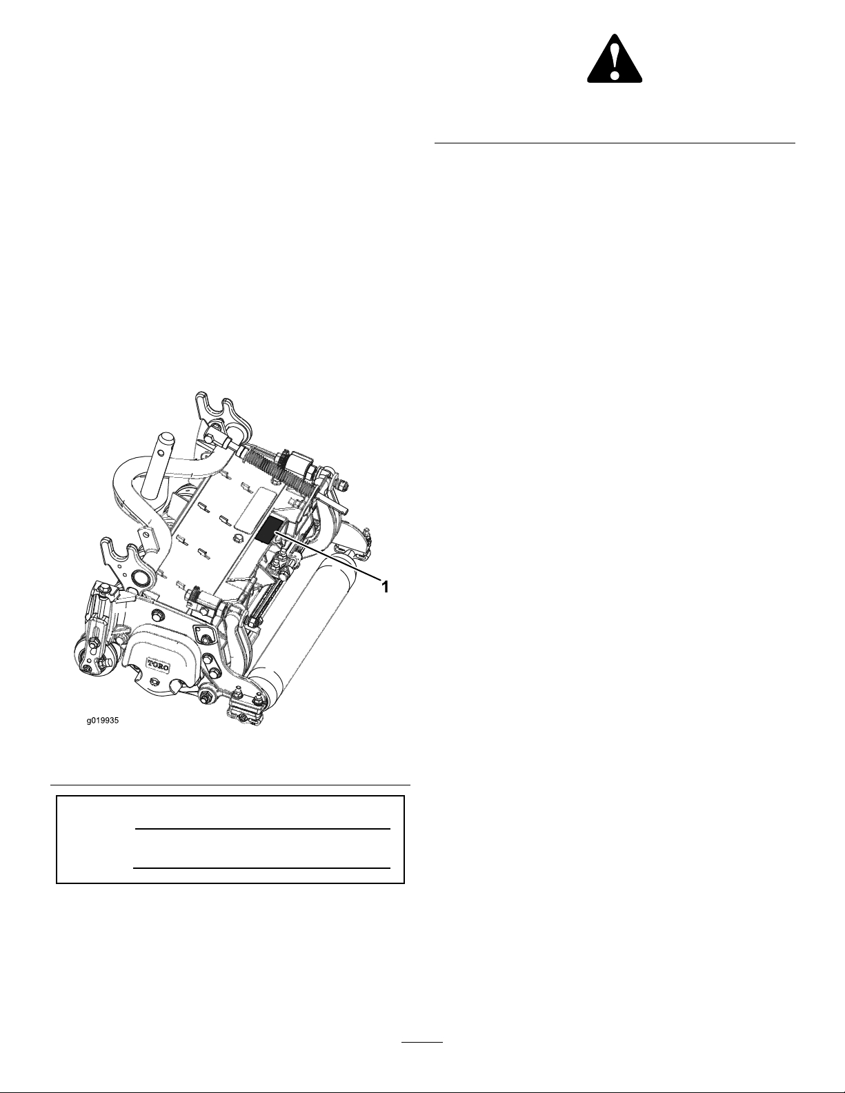
Figure2
Introduction
Readthisinformationcarefullytolearnhowtooperateand
maintainyourproductproperlyandtoavoidinjuryand
productdamage.Youareresponsibleforoperatingthe
productproperlyandsafely.
YoumaycontactTorodirectlyatwww.Toro.comforproduct
andaccessoryinformation,helpndingadealer,ortoregister
yourproduct.
Wheneveryouneedservice,genuineT oroparts,oradditional
information,contactanAuthorizedServiceDealerorToro
CustomerServiceandhavethemodelandserialnumbersof
yourproductready.Figure1identiesthelocationofthe
modelandserialnumbersontheproduct.Writethenumbers
inthespaceprovided.
1.Safetyalertsymbol
Thismanualuses2otherwordstohighlightinformation.
Importantcallsattentiontospecialmechanicalinformation
andNoteemphasizesgeneralinformationworthyofspecial
attention.
Contents
Introduction..................................................................2
Safety...........................................................................3
SafetyandInstructionalDecals.................................3
Setup............................................................................4
1Inspection............................................................4
2CuttingUnitKickstand..........................................4
3AdjustingtheRearShield.......................................5
4RepositioningtheCounterWeights..........................5
ProductOverview..........................................................7
Specications.........................................................7
CuttingUnitAccessoriesandKits(seeparts
catalogforpartnumbers)......................................7
Operation.....................................................................8
Adjustments...........................................................8
HeightofCutChartTerms......................................10
HeightofCutChart................................................12
ServicingtheBedknife............................................16
Maintenance.................................................................18
Lubrication............................................................18
ServicingtheBedbar...............................................18
ServicingtheHDDualPointAdjusters
(DPA)...............................................................20
ServicingtheRoller.................................................21
Figure1
1.Locationofthemodelandserialnumbers
ModelNo.
SerialNo.
Thismanualidentiespotentialhazardsandhassafety
messagesidentiedbythesafetyalertsymbol(Figure2),
whichsignalsahazardthatmaycauseseriousinjuryordeath
ifyoudonotfollowtherecommendedprecautions.
©2014—TheToro®Company
8111LyndaleAvenueSouth
Bloomington,MN55420
Contactusatwww.Toro.com.
2
PrintedintheUSA.
AllRightsReserved
Page 3
Safety
Hazardcontrolandaccidentpreventionaredependent
upontheawareness,concern,andpropertraining
ofthepersonnelinvolvedintheoperation,transport,
maintenance,andstorageofthemachine.Improper
useormaintenanceofthemachinecanresultininjury
ordeath.T oreducethepotentialforinjuryordeath,
complywiththefollowingsafetyinstructions.
•Read,understand,andfollowallinstructionsinthe
tractionunitoperatorsmanualbeforeoperatingthe
cuttingunit.
•Read,understand,andfollowallinstructionsinthis
operatorsmanualbeforeoperatingthecuttingunit.
•Neverallowchildrentooperatethetractionunitor
cuttingunits.Donotallowadultstooperatetractionunit
orcuttingunitswithoutproperinstruction.Onlytrained
operatorswhohavereadthismanualshouldoperatethe
cuttingunits.
•Neveroperatethecuttingunitswhenundertheinuence
ofdrugsoralcohol.
•Keepallshieldsandsafetydevicesinplace.Ifashield,
safetydeviceordecalisillegibleordamaged,repairor
replaceitbeforeoperationiscommenced.Alsotighten
anyloosenuts,bolts,andscrewstoensurecuttingunitis
insafeoperatingcondition.
•Alwayswearsubstantialshoes.Donotoperatecutting
unitswhilewearingsandals,tennisshoes,sneakersor
shorts.Also,donotwearloosettingclothingwhich
couldgetcaughtinmovingparts.Alwayswearlongpants
andsubstantialshoes.Wearingsafetyglasses,safetyshoes
andahelmetisadvisableandrequiredbysomelocal
ordinancesandinsuranceregulations.
•Removealldebrisorotherobjectsthatmightbepicked
upandthrownbythecuttingunitreelblades.Keepall
bystandersawayfromtheworkingarea.
•Ifthecuttingbladesstrikeasolidobjectortheunit
vibratesabnormally,stopandshuttheengineoff.Check
cuttingunitfordamagedparts.Repairanydamagebefore
restartingandoperatingthecuttingunit.
•Lowerthecuttingunitstothegroundandremovekey
fromignitionswitchwhenevermachineisleftunattended.
•Besurecuttingunitsareinsafeoperatingconditionby
keepingnuts,boltsandscrewstight.
•Removekeyfromignitionswitchtopreventaccidental
startingoftheenginewhenservicing,adjustingorstoring
themachine.
•Performonlythosemaintenanceinstructionsdescribedin
thismanual.Ifmajorrepairsareeverneededorassistance
isdesired,contactanAuthorizedT oroDistributor.
•Toensureoptimumperformanceandsafety ,always
purchasegenuineT ororeplacementpartsandaccessories
tokeeptheT oroallTORO.Neveruse"will-t"
replacementpartsandaccessoriesmadebyother
manufacturers.LookfortheT orologotoassure
genuineness.Usingunapprovedreplacementparts
andaccessoriescouldvoidthewarrantyofTheToro
Company.
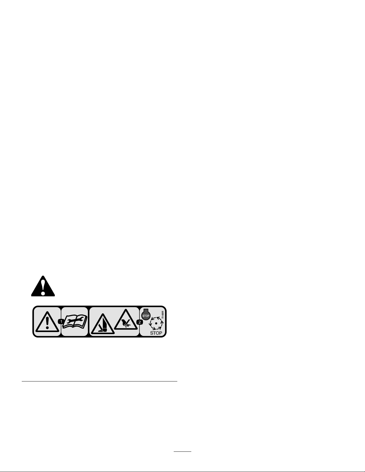
SafetyandInstructionalDecals.
Safetydecalsandinstructionsareeasilyvisibletotheoperatorandarelocatednearanyareaofpotential
danger.Replaceanydecalthatisdamagedorlost.
93–6688
1.Warning—readthe
Operator’sManualbefore
performingmaintenance.
2.Cuttinghazardofhandor
foot—stoptheengineand
waitforallmovingpartsto
stop.
3
Page 4

Setup
LooseParts
Usethechartbelowtoverifythatallpartshavebeenshipped.
ProcedureDescription
1
2
3
4
Cuttingunit
Nopartsrequired
Nopartsrequired
Nopartsrequired
MediaandAdditionalParts
Description
Partscatalog1
Operator'sManual
O-ring
Note:Determinetheleftandrightsidesofthemachine
fromthenormaloperatingposition.
Qty.
1Inspectthecuttingunit
–
–
–
Qty.
1
1Usewhenmountingreelmotortocuttingunit
Reviewthematerialandsaveinanappropriateplace:
Usethekickstandwhentippingthe
cuttingunit
Adjusttherearshield
Mountthecounterweights
Use
2
Use
1
Inspection
Partsneededforthisprocedure:
1
Cuttingunit
Procedure
Afterthecuttingunitisremovedfromthebox,inspectthe
following:
1.Checkeachendofthereelforgrease.Greaseshouldbe
visiblyevidentintheinternalsplinesofthereelshaft.
2.Ensurethatallnutsandboltsaresecurelytightened.
3.Makesurethecarrierframesuspensionoperatesfreely
anddoesnotbindwhenmovedbackandforth.
CuttingUnitKickstand
NoPartsRequired
Procedure
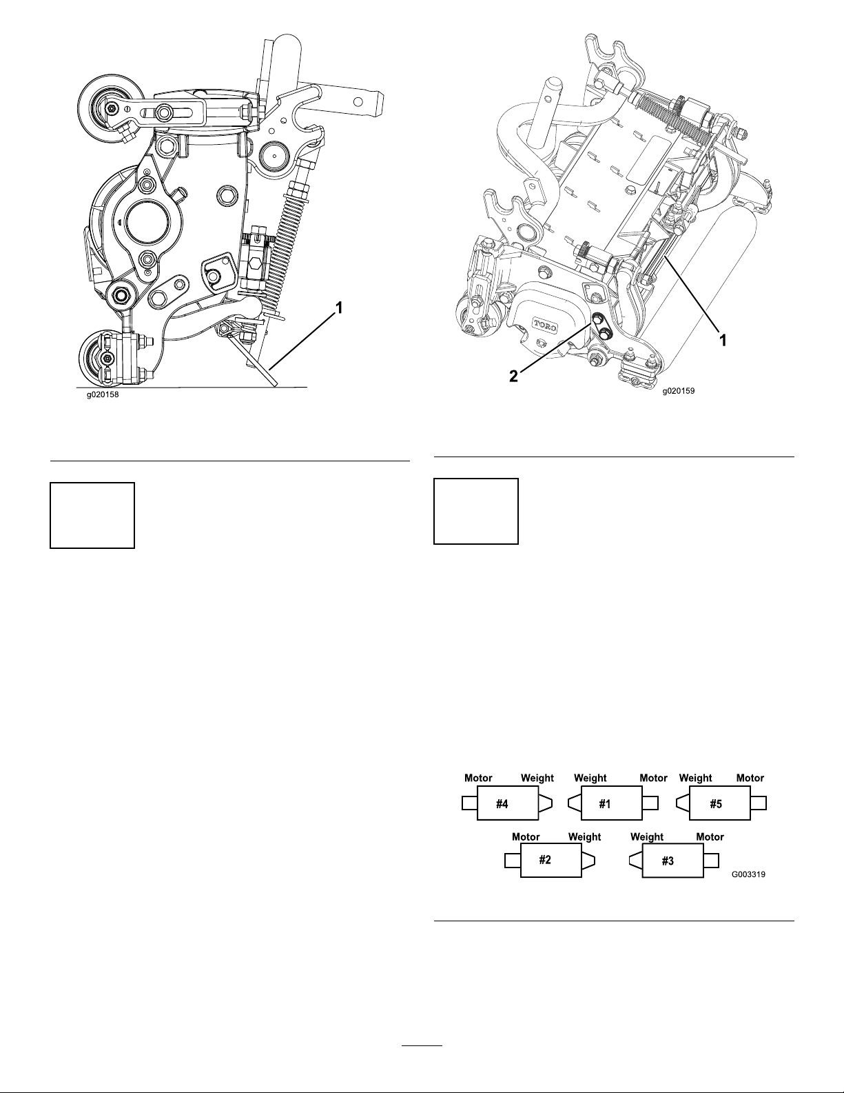
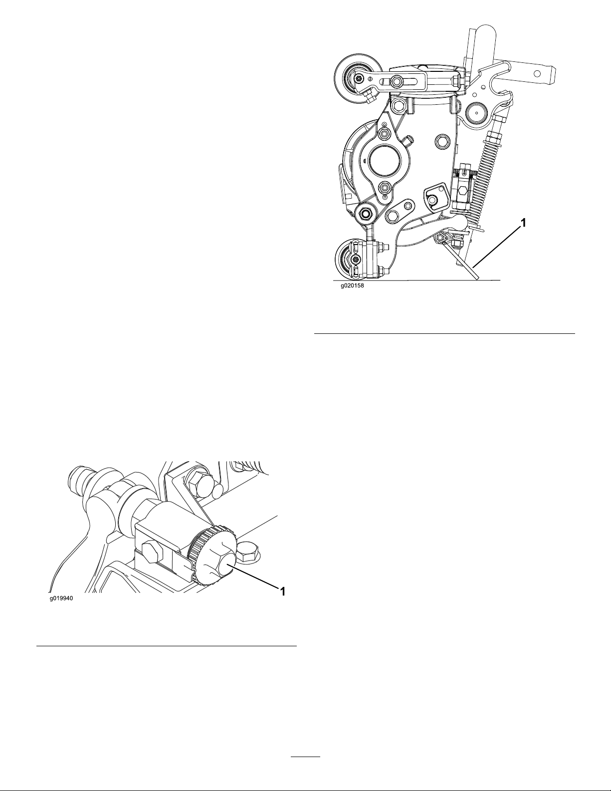
Wheneverthecuttingunithastobetippedtoexposethe
bedknife/reel,propuptherearofthecuttingunitwiththe
kickstand(suppliedwiththetractionunit)tomakesurethe
nutsonthebackendofthebedbaradjustingscrewsarenot
restingontheworksurface(Figure3).
4
Page 5
g020158
1.Cuttingunitkickstand
g020159
Figure3
1.Rearshield
Figure4
2.Capscrew
3
AdjustingtheRearShield
NoPartsRequired
Procedure
Undermostconditions,bestdispersionisattainedwhenthe
rearshieldisclosed(frontdischarge).Whenconditionsare
heavyorwet,rearshieldmaybeopened.
Toopentherearshield(Figure4),loosenthecapscrew
securingtheshieldtotheleftsideplate,rotatetheshieldto
theopenpositionandtightenthecapscrew.
4
RepositioningtheCounter Weights
NoPartsRequired
Procedure
Allcuttingunitsareshippedwiththecounterweightmounted
totheleftendofthecuttingunit.Usethefollowingdiagram
todeterminethepositionofthecounterweightsandreel
motors.
Figure5
1.Onthe#2and#4cuttingunits,removethe2lock
nutssecuringthecounterweighttotheleftendofthe
cuttingunit.Removethecounterweight(Figure6).
5
Page 6
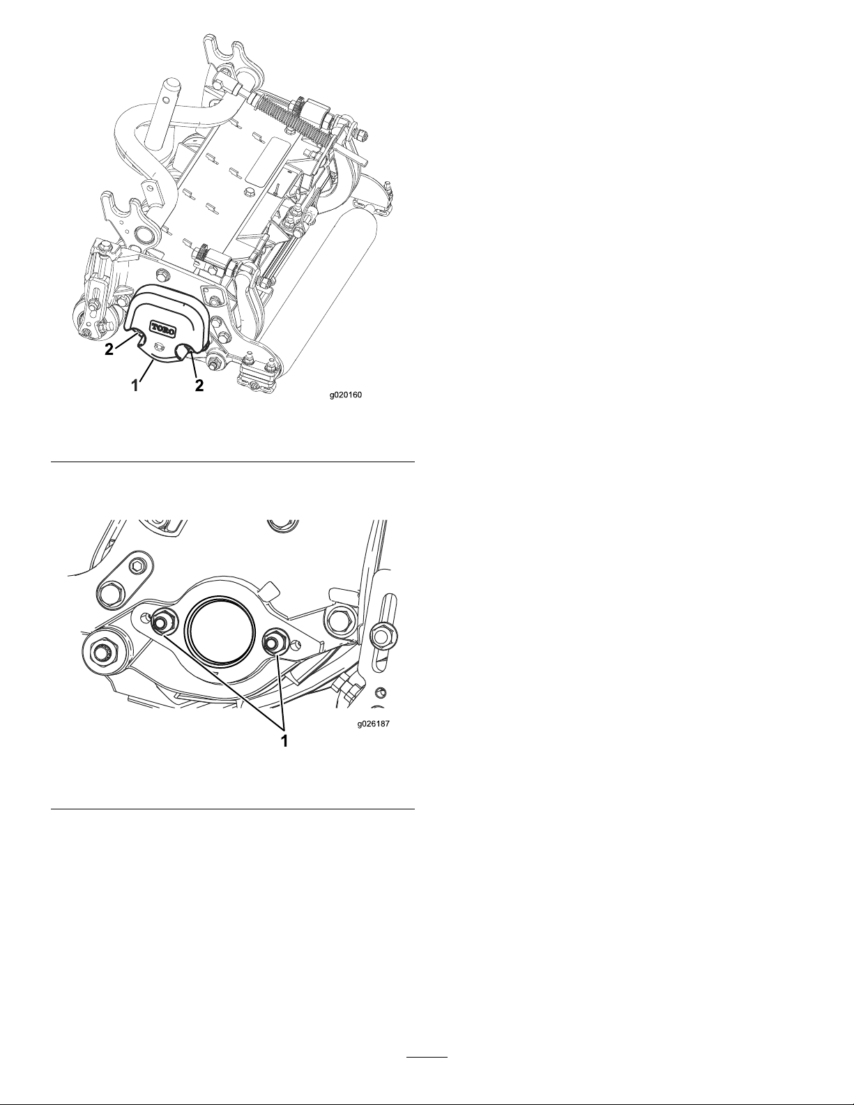
2
2
g020160
Figure6
g026187
1.Counterweight
2.Locknuts
2.Removethe2locknutsfromtherightsideplate
(Figure7).
Figure7
1.Locknut(2)
3.Installthecounterweighttotherightendofthe
cuttingunitandsecurewiththe2locknutspreviously
removed.
4.Installthe2reelmotormountinglocknutstotheleft
sideplateofthecuttingunit(Figure7).
6
Page 7

ProductOverview
Specications.
ModelNumberNetWeight
03911
03912
03913
39kg(86lb.)
40kg(88lb.)
43kg(94lb.)
CuttingUnitAccessoriesandKits(see partscatalogforpartnumbers)
Note:Allaccessoriesandkitsare1percuttingunitunless
otherwisespecied.
GrassBasketKit:Aseriesofclippingcollectionbaskets
attachedtothefrontofthecuttingunitstocollectgrass
clippings.
RearRollerBrushKit:Ahighspeed,highcontactbrush
thatkeepstherearrollerfreeofgrassanddebris,which
maintainsaconsistentheightofcutandpreventsclumping.
Thisleadstoabetterafter-cutappearance.
GroomerKit:Rotatingbladesassembledbehindthefront
rollerwhichprovidethebestmethodforreducinggrain
andspongyturfbystandingupthegrassbeforecutting.
Thegroomeralsoknocksoffdewfordecreasedstickiness
andclumping,opensupcanopyforbettergrassclipping
integration,andliftsgrassforacleancrispcut.Theoverall
designimprovesthequalityofcutforhealthierturfgrass
whileimprovingtheaftercutappearance
BroomerKit:Multiplebrushstripswovenintothehelical
groomerbladesimprovetheeffectivenessofthegroomerkit.
Performanceofthegroomerisenhancedbyenablingafull
width"Brooming"effectofturfwhileopeningupcanopy
forbettergrassclippingintegration.Thecombinationof
groomerandbroomersystemsoptimizethequalityofcutand
after-cutappearanceformoreconsistentplayingconditions.
Comb/ScraperKit:Axedcombinstalledbehindthefront
rollerwhichhelpsreducegrainandspongyturfbystanding
upthegrassbeforecutting.AscraperforthefrontWiehle
rollerisincludedinthekit.
HighHOCKit:Newfrontrollerbracketsandadditional
spacersfortherearrollerallowsthecuttingunittoachieve
heightsofcutabove25mm(1.00inch).Thenewfrontroller
bracketsalsomovethefrontrolleroutfarthertoimprove
after-cutappearanceattheseheightsofcut.
ShoulderRoller:Helpsreduceover-lapmarksforwarm
seasongrasses(Bermuda,Zoysia,Paspalum).
CollarKit(4neededperroller):Helpsreduceoverlap
marksforwarmseasongrasses(Bermuda,Zoysia,Paspalum).
Thiskitisinstalledontheouterthreegroovesoftheexisting
Wiehleroller,butisnotasaggressiveastheShoulderroller.
LongRearRoller:Helpsreduceover-lapmarksand
mismatchbetweencuttingunitsforwarmseasongrasses
(Bermuda,Zoysia,Paspalum).
FullFrontRoller:Helpsproducemorepronouncedstriping
(repeatedcuttinginthesamedirection/path),however,
effectiveheightofcutisraisedandqualityofcutisreduced.
Scrapers(Wiehle,Shoulder,RearRoller,FullFront
Roller):Fixedscrapersforalloptionalrollersareavailable
forreducinggrassbuilduponrollerswhichcanaffectheight
ofcutsettings.
RollerRebuildKit:Includesallthebearings,bearingnuts,
innersealsandoutersealsrequiredtorebuildaroller.
RollerRebuildT oolKit:Includesallthetoolsand
installationinstructionsrequiredtorebuildaroller.
7
Page 8
Operation
g020158
Note:Determinetheleftandrightsidesofthemachine
fromthenormaloperatingposition.
Adjustments
AdjustingtheBedknifetotheReel
Usethisproceduretosetthebedknifetothereelandtocheck
theconditionofthereelandbedknifeandtheirinteraction.
Aftercompletingthisprocedure,alwaystestthecutting
unitperformanceunderyoureldconditions.Youmay
needtomakefurtheradjustmentstoobtainoptimalcutting
performance.
Important:Donotovertightenthebedknifetothereel
oryouwilldamageit.
•Afterbacklappingthecuttingunitorgrindingthereel,you
mayneedtomowwiththecuttingunitforafewminutes
andthenperformthisproceduretoadjustthebedknifeto
thereelasthereelandbedknifeadjusttoeachother.
•Youmayneedadditionaladjustmentsiftheturfis
extremelydenseoryourcuttingheightisverylow .
Youwillneedthefollowingtoolstocompletethisprocedure:
•Shim0.05mm(0.002inch)—Toropartnumber125-5611
•Cuttingperformancepaper—Toropartnumber125-5610
1.Positionthecuttingunitonaat,levelworksurface.
Turnthebedbaradjustingscrewscounterclockwiseto
ensurethatthebedbardoesnotcontactthereel(Figure
8).
Figure9
1.Cuttingunitkickstand
3.Rotatethereelsothatabladecrossesthebedknife
approximately25mm(1inch)infromtheendofthe
bedknifeontherighthandsideofthecuttingunit.
Puttinganidentifyingmarkonthisbladewillmake
subsequentadjustmentseasier.Insertthe0.05mm
(0.002inch)shimbetweenthemarkedreelbladeand
thebedknifeatthepointwherethebladecrossesthe
bedknife.
4.Turntherightbedbaradjusterclockwiseuntilyoufeel
lightpressure(i.e.drag)ontheshim,thenbackoffthe
bedbaradjustertwoclicksandremovetheshim.(Since
adjustingonesideofthecuttingunitaffectstheother
side,thetwoclickswillprovideclearanceforwhenthe
othersideisadjusted)
Figure8
1.Bedbaradjustingscrew
2.Tipthemower,toexposethebedknifeandreel.
Important:Makesurenutsonbackendofbedbar
adjustingscrewsarenotrestingonthework
surface(Figure9).
Note:Ifstartingwithalargegap,bothsidesshould
initiallybedrawncloserbyalternatelytighteningthe
rightandlefthandsides.
5.Slowlyrotatethereelsothatthesamebladethatyou
checkedontherightsideiscrossingthebedknife
approximately25mm(1inch)infromtheendofthe
bedknifeonthelefthandsideofthecuttingunit.
6.Turntheleftbedbaradjusterclockwiseuntiltheshim
canbeslidthroughthereeltobedknifegapwithlight
drag.
7.Returntotherightsideandadjustasnecessarytoget
lightdragontheshimbetweenthesamebladeand
bedknife.
8.Repeatsteps6and7untiltheshimcanbeslidthrough
bothgapswithslightdrag,butoneclickinonboth
8
Page 9

sidespreventstheshimfrompassingthroughonboth
g020161
g020162
sides.Thebedknifeisnowparalleltothereel.
Note:Thisprocedureshouldnotbeneededondaily
adjustments,butshouldbedoneaftergrindingor
disassembly.
9.Fromthisposition(i.e.oneclickinandshimnot
passingthrough)turnthebedbaradjustersclockwise
twoclickseach.
Note:Eachclickturnedmovesthebedknife0.018
mm(0.0007inches).Donotovertightenthe
adjustingscrews.
10.Testthecuttingperformancebyinsertingalongstrip
ofcuttingperformancepaper(T oropartnumber
125-5610)betweenreelandbedknife,perpendicular
tothebedknife(Figure10).Slowlyrotatethereel
forward;itshouldcutthepaper.
Figure10
Note:Shouldexcessivereeldragbeevident,itwillbe
eithernecessarytobacklaporregrindthecuttingunit
toachievethesharpedgesneededforprecisioncutting.
Figure11
1.Spacer3.Sideplatemountingange
2.Rollerbracket
2.Raiserearofcuttingunitandplaceablockunder
bedknife.
3.Remove(2)nutssecuringeachrollerbracketandspacer
toeachsideplatemountingange.
4.Lowerrollerandscrewsfromsideplatemounting
angesandspacers.
5.Placespacersontoscrewsonrollerbrackets.
6.Re-securerollerbracketandspacerstounderside
ofsideplatemountingangeswithnutspreviously
removed.
7.Verifythatbedknifetoreelcontactiscorrect.Tip
mowertoexposefrontandrearrollersandbedknife.
Note:Thepositionoftherearrollertothereel
iscontrolledbythemachiningtolerancesofthe
assembledcomponentsandparallelingisnotrequired.
Alimitedamountofadjustmentispossiblebysetting
thecuttingunitonasurfaceplateandlooseningthe
sideplatemountingcapscrews(Figure12).Adjustand
retightencapscrews.Torquethecapscrewsto37-45
N-m(27-33ft-lb).
AdjustingtheRearRoller
1.Adjusttherearrollerbrackets(Figure11)tothedesired
heightofcutrangebypositioningtherequiredamount
ofspacersbelowthesideplatemountingange(Figure
11)pertheHOCChart.
Figure12
1.Sideplatemountingcapscrews
9
Page 10

HeightofCutChartTerms
g020164
HeightofCutSetting(HOC)
ThedesiredHeightofCut.
BenchSetHeightofCut
Theheightatwhichthetopedgeofthebedknifeissetabove
aatlevelsurfacethatcontactsthebottomofboththefront
andrearroller.
EffectiveHeightofCut
Thisistheactualheightthegrasshasbeencut.Foragiven
benchsetheightofcut,theactualheightofcutwillvary
dependingonthetypeofgrass,timeofyear,turfandsoil
conditions.Thecuttingunitsetup(aggressivenessofcut,
rollers,bedknives,attachmentsinstalled,turfcompensation
settings,etc.)willalsoaffecttheeffectiveheightofcut.Check
theeffectiveheightofcutusingtheTurfEvaluator,Model
04399regularlytodeterminethedesiredbenchsetheight
ofcut.
AggressivenessofCut
Zoysia)whilecoolseasongrasses(Bent,Bluegrass,Rye)may
requirenormaltomoreaggressivesetups.Moreaggressive
setupscutmoregrassoffbyallowingthespinningreeltopull
moregrassupintothebedknife.
RearSpacers
Thenumberofrearspacersdeterminestheaggressiveness
ofcutforthecuttingunit.Foragivenheightofcut,adding
spacers,belowthesideplatemountingange,increasesthe
aggressivenessofthecuttingunit.Allcuttingunitsona
givenmachinemustbesettothesameaggressivenessofcut
(Numberofrearspacers,partno.119–0626),otherwisethe
after-cutappearancecouldbenegativelyaffected(Figure13).
TurfCompensationSettings
Theturfcompensationspringtransferstheweightfromthe
fronttotherearroller.(Thishelpstoreduceawavepattern
intheturf,alsoknownasmarcellingorbobbing.)
Important:Makespringadjustmentswiththecutting
unitmountedtothetractionunit,pointingstraight
aheadandloweredtotheshopoor.
1.Makesurethehairpincotterisinstalledintherearhole
inthespringrod(Figure14).
CuttingunitAggressivenessofCuthasasignicantimpact
ontheperformanceofthecuttingunit.Aggressivenessof
Cutreferstotheangleofthebedkniferelativetotheground
(Figure13).
Figure13
1.Rearspacers
2.Sideplatemountingange
Thebestcuttingunitsetupisdependentonyourturf
conditionsanddesiredresults.Experiencewiththecutting
unitonyourturfwilldeterminethebestsettingtouse.
Aggressivenessofcutmaybeadjustedthroughoutthecutting
seasontoallowforvariousturfconditions.
Ingeneral,lesstonormalaggressivesettingsaremore
appropriateforwarmseasongrasses(Bermuda,Paspalum,
3.Aggressivenessofcut
Figure14
1.Turfcompensationspring3.Springrod
2.Hairpincotter4.Hexnuts
2.Tightenthehexnutsonthefrontendofthespringrod
untilthecompressedlengthofthespringis5inches
(12.7cm)(Figure14).
Note:Whenoperatingonroughterraindecreasethe
springlengthby1.3cm(1/2inch).Groundfollowing
willbeslightlydecreased.
Note:Theturfcompensationsettingwillneedtobe
resetiftheHOCsettingortheAggressivenessofCut
settingischanged.
10
Page 11

ChainLinks
Thelocationatwhichtheliftarmchainisattacheddetermines
therearrollerpitchangle(Figure15).
Figure15
1.Liftchain
2.U-Bracket
3.Bottomhole
11
Page 12

Groomer
Thesearetherecommendedheightofcutsettingswhenagroomerkitisinstalledonthecuttingunit.
HeightofCutChart
HOCSettingAggressivenessofCutNo.ofRearSpacersNo.ofChainLinksWithGroomerkits
0.64cm(0.250inches)
0.95cm(0.375inches)
1.27cm(0.500inches)
1.56cm(0.625inches)
1.91cm(0.750inches)
2.22cm(0.875inches)
2.54cm(1.000inch)
2.86cm(1.125inches)*
3.18cm(1.250inches)*
3.49cm(1.375inches)*
3.81cm(1.500inches)*
+IndicatestheU-bracket,onliftarm,ispositionedinthebottomhole(Figure15).
*HighHOCKit(PartNo.1 10-9600)mustbeinstalled.FrontHOCbracketmustbepositionedinthetopsideplatehole.
Less
Normal
More
Less
Normal
More
Less
Normal
More
Less
Normal
More
Less
Normal
More
Less
Normal
More
Less
Normal
More
Less
Normal
More
Less
Normal
More
Less
Normal
More
Less
Normal
More
0
0
1
0
1
2
0
1
2
1
2
3
2
3
4
2
3
4
3
4
5
4
5
6
4
5
6
4
5
6
5
6
7
4
4
3
4
3+
3+
4
4
3+
4
4
3+
4
3+
3+
4
3
3
4
3+
3+
4
3+
3
4
3+
3
4
4
3+
4
3+
3+
installed
Y
Y
-
Y
Y
-
Y
Y
Y
Y
Y
-
Y
Y
-
Y
Y
-
Y
Y
-
-
-
-
-
-
-
-
-
-
-
-
-
Note:Changingonechainlinkwillchangetherearrollerpitchanglemovementby7.0degrees.
Note:ChangingtheU-bracket,ontheliftarm,tothebottomholewilladd3.5degreestotherearrollerpitchangle
12
Page 13

AdjustingtheHeightofCut
g020166
Note:Forheightsofcutgreaterthan2.54cm(1.000inch)
theHighHeightofCutKitmustbeinstalled.
1.Loosenlocknutssecuringheight-of-cutbracketsto
cuttingunitsideplates(Figure16).
Figure16
1.Adjustingscrew
2.Locknut
2.Loosennutongaugebar(Figure17)andsetadjusting
screwtodesiredheight-of-cut.Distancebetween
bottomofscrewheadandfaceofbarisheight-of-cut.
3.Height-of-cutbracket
Figure18
Important:Whensetproperly,therearandfront
rollerswillcontactthegaugebarandthescrew
willbesnugagainstthebedknife.Thisensures
thattheheight-of-cutisidenticalatbothendsof
thebedknife.
5.Tightennutstosecureadjustment.Donotovertighten
nut.Tightenenoughtoremoveplayfromwasher.
Usethefollowingcharttodeterminewhichbedknifeis
bestsuitedforthedesiredheightofcut.
Figure17
1.Gaugebar4.Holesusedforsetting
GroomerHOG
2.Heightadjustingscrew5.Holenotused
3.Nut
3.Hookthescrewheadoncuttingedgeofbedknifeand
restrearendofbaronrearroller(Figure18).
4.Rotatetheadjustingscrewuntilthefrontrollercontacts
thegaugebar(Figure18).Adjustbothendsofroller
untilentirerollerisparalleltothebedknife.
13
Page 14

PremiumLowHOCBedknife
Bedknife/HeightofCutChart
ReelSize
18inch,11
blade(Production)
18inch,8blade(Optional)
22inch,8blade(Optional)
LowHOCBedknife
ReelSize
18inch,8&11blade
(Optional)
22inch,8blade(Optional)
EdgeMax®LowHOCBedknife
ReelSize
18inch,1 1blade(Optional)
18inch,8blade(Optional)
22inch,8blade(Optional)
EdgeMax®Bedknife
ReelSize
18inch,8blade(Production)
18inch,11blade(Optional)
22inch,8blade(Production)
PartNo.
125–2770
125–2771
PartNo.
121-3167
110-4084
PartNo.
130–4745
127–7132
PartNo.
121–3165
108-9095
BedknifeLipHeightHeightofCut
5.6mm
(.220inch)
BedknifeLipHeightHeightofCut
5.6mm
(.220inch)
BedknifeLipHeightHeightofCut
5.6mm
(.220inch)
BedknifeLipHeightHeightofCut
6.9mm
(.270inch)
6.4–12.7mm
(.250-.500inch)
.6.4–12.7mm
(.250-.500inch))
6.4–12.7mm
(.250-.500inch)
9.5–38.1mm
(.375-1.50inches)
StandardBedknife
ReelSize
18inch,8&11blade
(Optional)
22inch,8blade(Optional)
PartNo.
121–3166
108-9096
*WarmseasongrassesmayrequiretheLowHOC
bedknifefor12.7mm(.500inches)andbelow.
Figure19
1.BedknifeLipHeight*
CuttingUnitCharacteristics
Thedualknobbedknife-to-reeladjustmentsystem
incorporatedinthiscuttingunitsimpliestheadjustment
procedureneededtodeliveroptimummowingperformance.
Thepreciseadjustmentpossiblewiththedualknob/bedbar
designgivesthenecessarycontroltoprovideacontinual
self-sharpeningaction-thusmaintainingsharpcuttingedges,
BedknifeLipHeightHeightofCut
6.9mm
(.270inch)
9.5–38.1mm
(.375-1.50inches)*
ensuringgoodquality-of-cut,andgreatlyreducingtheneed
forroutinebacklapping.
DailyAdjustmentsofCuttingUnit
Priortomowingeachday,orasrequired,checkeachcutting
unittoverifyproperbedknife-to-reelcontact.Thismustbe
performedeventhoughthequalityofcutisacceptable.
1.Slowlyrotatethereelinareversedirection,listening
forreel-to-bedknifecontact.
Note:Theadjustmentknobshavedetents
correspondingto0.018mm(0.0007inch)bedknife
movementforeachindexedposition.Referto
AdjustingtheBedknifetotheReel.
2.Testthecuttingperformancebyinsertingalongstrip
ofcuttingperformancepaper(T oropartnumber
125-5610)betweenreelandbedknife,perpendicular
tothebedknife(Figure20).Slowlyrotatethereel
forward;itshouldcutthepaper.
14
Page 15

Figure20
Note:Ifexcessivecontact/reeldragisevidentitwill
beeithernecessarytobacklap,refacethefrontofthe
bedknife,orregrindthecuttingunittoachievethe
sharpedgesneededforprecisioncutting(Refertothe
ToroManualforSharpeningReelandRotaryMowers,
FormNo.09168SL).
Important:Lightcontactispreferredatalltimes.
Ifyoudonotmaintainlightcontact,thebedknife
andreeledgeswillnotsufcientlyself-sharpen
andwilldullafteraperiodofoperation.Ifyou
maintainexcessivecontact,thebedknifeandreel
willwearquicker,wearunevenly,andthequality
ofcutmaybeadverselyaffected.
Note:Afterextendedrunning,aridgewilleventually
developatbothendsofthebedknife.Roundoffor
lethesenotchesushwiththecuttingedgeofthe
bedknifetoensuresmoothoperation.
Note:Overtime,thechamfer(Figure21)willneedto
beregroundasitisonlydesignedtolast40%ofthe
bedknifelife.
Figure21
Note:Donotmakethelead-inchamfertoolargeas
itmaycauseturftufting.
15
Page 16

ServicingtheBedknife
Thebedknifeservicelimitsarelistedinthefollowingcharts.
Important:Operatingthecuttingunitwiththebedknifebelowthe“servicelimit”mayresultinpoorafter-cut
appearanceandreducethestructuralintegrityofthebedknifeforimpacts.
BedknifeServiceLimitChart
PremiumLowHOCBedknife
ReelSize
18inch,11blade(Production)
18inch,8blade(Optional)
22inch,8blade(Optional)
LowHOCBedknife
ReelSize
18inch,8&1 1blade(Optional)
22inch,8blade(Optional)
EdgeMax®LowHOCBedknife
ReelSize
18inch,11blade(Optional)
18inch,8blade(Optional)
22inch,8blade(Optional)
EdgeMax®Bedknife
ReelSize
18inch,8blade(Production)
18inch,1 1blade(Optional)
22inch,8blade(Production)
PartNo.
125-2770
125-2771
PartNo.
121-3167
110-4084
PartNo.
130–4745
127–7132
PartNo.
121–3165
108-9095
BedknifeLipHeightServiceLimit*GrindAngles
5.6mm
(.220inch)
BedknifeLipHeightServiceLimit*GrindAngles
5.6mm
(.220inch)
BedknifeLipHeightServiceLimit*GrindAngles
5.6mm
(.220inch)
BedknifeLipHeightServiceLimit*GrindAngles
6.9mm
(.270inch)
4.8mm
(.190inch)
4.8mm
(.190inch)
4.8mm
(.190inch)
4.8mm
(.190inch)
Top/FrontAngles
10/5Degrees
Top/FrontAngles
5/5Degrees
Top/FrontAngles
10/5Degrees
Top/FrontAngles
5/5Degrees
StandardBedknife
22inch,8blade(Optional)
ReelSize
18inch,8&11blade
(Optional)
PartNo.
121–3166
108-9096
BedknifeLipHeightServiceLimit*GrindAngles
6.9mm
(.270inch)
4.8mm
(.190inch)
Top/FrontAngles
5/5Degrees
16
Page 17

RecommendedT opandFrontBedknifeGrindAngles
g025579
2
3
(Figure22).
Figure22
1.Bedknifeservicelimit*
2.Topgrindangle
3.Frontgrindangle
Note:Allbedknifeservicelimitmeasurementsreferencethe
bottomofthebedknife(Figure23)
Figure23
17
Page 18

Maintenance
g020156
Lubrication
Eachcuttingunithas(4)greasettingsthatmustbelubricated
regularlywithNo.2GeneralPurposeLithiumBaseGrease.
Thelubricationpointsarethefrontroller(2)andtherear
roller(2).Also,afterevery250hoursorwheneverthereel
motorisremovedfromthecuttingunit,applygreasetothe
splineinsert(Figure24).
Note:Lubricatingcuttingunitsimmediatelyafter
washinghelpspurgewateroutofbearingsandincreases
bearinglife.
Figure25
1.Bedbaradjustingscrew3.Bedbar
2.Springtensionnut
4.Washer
1.Wipeeachgreasettingwithacleanrag.
2.Greasethettingsandsplineinsert.
3.Wipeexcessgreaseaway.
Figure24
Greasettinglocationsshownforleftside
2.Backoutthespringtensionnut,untilthewasherisno
longertensionedagainstthebedbar(Figure25).
3.Oneachsideofthemachine,loosenthelocknut
securingthebedbarbolt(Figure26).
Figure26
1.Bedbarbolt2.Locknut
4.Removeeachbedbarboltallowingbedbartobepulled
downwardandremovedfrommachinebolt(Figure
26).Accountfor2nylonand1stampedsteelwashers
oneachendofbedbar(Figure27).
ServicingtheBedbar
RemovingtheBedbar
1.Turnbedbaradjusterscrewscounterclockwisetoback
thebedknifeawayfromreel(Figure25).
Figure27
1.Bedbarbolt
2.Nut4.Nylonwasher
AssemblingtheBedbar
1.Installbedbar,positioningmountingearsbetween
washerandbedbaradjuster.
2.Securebedbartoeachsideplatewithbedbarbolts
(nutsonbolts)and6washers.Anylonwasheristobe
positionedoneachsideofsideplateboss.Placeasteel
18
3.Steelwasher
Page 19

washeroutsideeachofthenylonwashers(Figure27).
Torquebedbarboltsto27-33(37-45N-m).Tighten
thelocknutsequally ,oneachside,untiltheoutersteel
washerscannotberotatedbyhand.Then,loosenthe
locknutsuntiltheoutersteelwashersjustrotateby
hand,yetthebedbarendplayisremoved.
Note:Overtighteningthelocknutscandeecttheside
platesandbedbarwhichcanaffectthereel/bedknife
contact.
Note:Thewashersontheinsidemayhaveagap.
3.Tightenspringtensionnutuntilspringiscollapsed,
thenbackoff1/2turn(Figure28).
Note:Donotovertightenasdamagetothespring
mayoccur.
Figure28
1.Spring2.Springtensionnut
19
Page 20

ServicingtheHDDualPoint
1
2
3
4
5
6
7
8
9
10
11
G016355
Adjusters(DPA)
1.Removeallparts(refertoInstallationInstructionsforHD
DPAKitModelNo.120–7230andtoFigure29).
2.ApplyNeverSeizetotheinsideofthebushingareaon
cuttingunitcenterframe(Figure29).
3.Alignthekeysonangebushingstotheslotsinthe
frameandinstallthebushings(Figure29).
4.Installawavewasherontotheadjustershaftandslide
theadjustershaftintotheangebushingsinthecutting
unitframe(Figure29).
5.Securetheadjustershaftwithaatwasherandlock
nut(Figure29).T orquethelocknutto15to20ft-lb
(20to27N-m).
Note:Thebedbaradjustershafthasleft-handthreads.
6.ApplyNeverSeizelubricanttothethreadsofthe
bedbaradjusterscrewthattintotheadjustershaft.
Threadbedbaradjusterscrewintotheadjustershaft.
7.Looselyinstallthehardenedwasher,springandspring
tensionnutontoadjusterscrew .
8.Installthebedbar,positioningthemountingears
betweenwasherandbedbaradjuster.
9.Securethebedbartoeachsideplatewiththebedbar
bolts(nutsonbolts)and6washers.Anylonwasheris
tobepositionedoneachsideofsideplateboss.Placea
steelwasheroutsideeachofthenylonwashers(Figure
29).T orquebedbarboltsto27-33ft.-lb(37-45N-m).
Tightenthelocknutsequally ,oneachside,untilthe
outersteelwasherscannotberotatedbyhand.Then,
loosenthelocknutsuntiltheoutersteelwashersjust
rotatebyhand,yetthebedbarendplayisremoved
(Figure27).
10.Tightenthenutoneachbedbaradjusterassembly
untilthecompressionspringisfullycompressed,then
loosennut1/2turn(Figure28).
11.Repeattheprocedureontheotherendofthecutting
unit.
12.Adjustthebedknifetothereel.
Figure29
1.Shaftadjuster4.ApplyNeverSeizehere7.ApplyNeverSeizehere10.Compressionspring
2.Wavewasher5.Flatwasher8.Bedbaradjusterscrew
3.Flangebushing6.Locknut9.Hardenedwasher
20
11.Springtensionnut
Page 21

ServicingtheRoller
ARollerRebuildKit,PartNo.114–5430anda
RollerRebuildT oolKit,PartNo.115–0803(Figure
30)areavailableforservicingtheroller.TheRoller
RebuildKitincludesallthebearings,bearingnuts,
innersealsandoutersealstorebuildaroller.
TheRollerRebuildToolKitincludesallthetoolsandthe
installationinstructionsrequiredtorebuildaroller.Referto
yourpartscatalogorcontactyourdistributorforassistance.
Figure30
1.Rebuildkit(PartNo.114–5430)
2.Rebuildtoolkit(PartNo.1 15–0803)
3.Innerseal8.Washer
4.Bearing
5.Outerseal
6.Bearingnut
7.Innersealtool
9.Bearing/outersealtool
21
Page 22

Notes:
22
Page 23

DeclarationofIncorporation
TheT oroCompany,8111LyndaleAve.South,Bloomington,MN,USAdeclaresthatthefollowingunit(s)
conform(s)tothedirectiveslisted,wheninstalledinaccordancewiththeaccompanyinginstructionsontocertain
ToromodelsasindicatedontherelevantDeclarationsofConformity.
ModelNo.
03911313000001andUp
03912313000001andUp
03913313000001andUp
SerialNo.
ProductDescriptionInvoiceDescription
18-inch,8-bladeDP ACutting
UnitforReelmaster3550
SeriesTractionUnit
18-inch,11-bladeDPA
CuttingUnitforReelmaster
3550SeriesTractionUnit
22-inch,8-bladeDP ACutting
UnitforReelmaster3550
SeriesTractionUnit
RM355018”8BLDDP A
CUTTINGUNIT
RM355018”1 1BLDDPA
CUTTINGUNIT
RM355022”8BLDDP A
CUTTINGUNIT
GeneralDescription
CuttingUnit
CuttingUnit
CuttingUnit
Directive
2000/14/EC
2006/42/EC
2000/14/EC
2006/42/EC
2000/14/EC
2006/42/EC
RelevanttechnicaldocumentationhasbeencompiledasrequiredperPartBofAnnexVIIof2006/42/EC.
Wewillundertaketotransmit,inresponsetorequestsbynationalauthorities,relevantinformationonthispartly
completedmachinery.Themethodoftransmissionshallbeelectronictransmittal.
ThismachineryshallnotbeputintoserviceuntilincorporatedintoapprovedToromodelsasindicatedonthe
associatedDeclarationofConformityandinaccordancewithallinstructions,wherebyitcanbedeclaredin
conformitywithallrelevantDirectives.
Certied:EUTechnicalContact:
PeterT etteroo
ToroEuropeNV
B-2260Oevel-Westerloo
Belgium
DavidKlisTel.003214562960
Sr.EngineeringManager
811 1LyndaleAve.South
Bloomington,MN55420,USA
May29,2012
Fax003214581911
23
Page 24

TheToroTotalCoverageGuarantee
ALimitedWarranty
ConditionsandProductsCovered
TheToroCompanyanditsafliate,ToroWarrantyCompany,pursuant
toanagreementbetweenthem,jointlywarrantyourT oroCommercial
product(“Product”)tobefreefromdefectsinmaterialsorworkmanship
fortwoyearsor1500operationalhours*,whicheveroccursrst.This
warrantyisapplicabletoallproductswiththeexceptionofAerators
(refertoseparatewarrantystatementsfortheseproducts).Wherea
warrantableconditionexists,wewillrepairtheProductatnocosttoyou
includingdiagnostics,labor,parts,andtransportation.Thiswarranty
beginsonthedatetheProductisdeliveredtotheoriginalretailpurchaser.
*Productequippedwithanhourmeter.
InstructionsforObtainingWarrantyService
YouareresponsiblefornotifyingtheCommercialProductsDistributoror
AuthorizedCommercialProductsDealerfromwhomyoupurchasedthe
Productassoonasyoubelieveawarrantableconditionexists.Ifyouneed
helplocatingaCommercialProductsDistributororAuthorizedDealer,or
ifyouhavequestionsregardingyourwarrantyrightsorresponsibilities,
youmaycontactusat:
ToroCommercialProductsServiceDepartment
ToroWarrantyCompany
811 1LyndaleAvenueSouth
Bloomington,MN55420-1196
952–888–8801or800–952–2740
E-mail:commercial.warranty@toro.com
OwnerResponsibilities
AstheProductowner,youareresponsibleforrequiredmaintenanceand
adjustmentsstatedinyourOperator'sManual.Failuretoperformrequired
maintenanceandadjustmentscanbegroundsfordisallowingawarranty
claim.
ItemsandConditionsNotCovered
Notallproductfailuresormalfunctionsthatoccurduringthewarranty
periodaredefectsinmaterialsorworkmanship.Thiswarrantydoesnot
coverthefollowing:
•Productfailureswhichresultfromtheuseofnon-T ororeplacement
parts,orfrominstallationanduseofadd-on,ormodiednon-Toro
brandedaccessoriesandproducts.Aseparatewarrantymaybe
providedbythemanufactureroftheseitems.
•Productfailureswhichresultfromfailuretoperformrecommended
maintenanceand/oradjustments.Failuretoproperlymaintainyour
ToroproductpertheRecommendedMaintenancelistedinthe
Operator’sManualcanresultinclaimsforwarrantybeingdenied.
•ProductfailureswhichresultfromoperatingtheProductinanabusive,
negligent,orrecklessmanner.
•Partssubjecttoconsumptionthroughuseunlessfoundtobedefective.
Examplesofpartswhichareconsumed,orusedup,duringnormal
Productoperationinclude,butarenotlimitedto,brakepadsand
linings,clutchlinings,blades,reels,rollersandbearings(sealedor
greasable),bedknives,sparkplugs,castorwheelsandbearings,tires,
lters,belts,andcertainsprayercomponentssuchasdiaphragms,
nozzles,andcheckvalves,etc.
•Failurescausedbyoutsideinuence.Conditionsconsideredtobe
outsideinuenceinclude,butarenotlimitedto,weather,storage
practices,contamination,useofunapprovedfuels,coolants,lubricants,
additives,fertilizers,water,orchemicals,etc.
•Failureorperformanceissuesduetotheuseoffuels(e.g.gasoline,
diesel,orbiodiesel)thatdonotconformtotheirrespectiveindustry
standards.
•Normalnoise,vibration,wearandtear ,anddeterioration.
•Normal“wearandtear”includes,butisnotlimitedto,damagetoseats
duetowearorabrasion,wornpaintedsurfaces,scratcheddecalsor
windows,etc.
Parts
Partsscheduledforreplacementasrequiredmaintenancearewarranted
fortheperiodoftimeuptothescheduledreplacementtimeforthatpart.
Partsreplacedunderthiswarrantyarecoveredforthedurationofthe
originalproductwarrantyandbecomethepropertyofT oro.Torowillmake
thenaldecisionwhethertorepairanyexistingpartorassemblyorreplace
it.T oromayuseremanufacturedpartsforwarrantyrepairs.
DeepCycleandLithium-IonBatteryWarranty:
DeepcycleandLithium-Ionbatterieshaveaspeciedtotalnumberof
kilowatt-hourstheycandeliverduringtheirlifetime.Operating,recharging,
andmaintenancetechniquescanextendorreducetotalbatterylife.Asthe
batteriesinthisproductareconsumed,theamountofusefulworkbetween
chargingintervalswillslowlydecreaseuntilthebatteryiscompletelyworn
out.Replacementofwornoutbatteries,duetonormalconsumption,
istheresponsibilityoftheproductowner.Batteryreplacementmaybe
requiredduringthenormalproductwarrantyperiodatowner’sexpense.
Note:(Lithium-Ionbatteryonly):ALithium-Ionbatteryhasapartonly
proratedwarrantybeginningyear3throughyear5basedonthetime
inserviceandkilowatthoursused.RefertotheOperator'sManualfor
additionalinformation.
MaintenanceisatOwner’sExpense
Enginetune-up,lubrication,cleaningandpolishing,replacementoflters,
coolant,andcompletingrecommendedmaintenancearesomeofthe
normalservicesT oroproductsrequirethatareattheowner’sexpense.
GeneralConditions
RepairbyanAuthorizedToroDistributororDealerisyoursoleremedy
underthiswarranty.
NeitherTheToroCompanynorToroWarrantyCompanyisliablefor
indirect,incidentalorconsequentialdamagesinconnectionwiththe
useoftheToroProductscoveredbythiswarranty,includingany
costorexpenseofprovidingsubstituteequipmentorserviceduring
reasonableperiodsofmalfunctionornon-usependingcompletion
ofrepairsunderthiswarranty.ExceptfortheEmissionswarranty
referencedbelow,ifapplicable,thereisnootherexpresswarranty.All
impliedwarrantiesofmerchantabilityandtnessforusearelimitedto
thedurationofthisexpresswarranty.
Somestatesdonotallowexclusionsofincidentalorconsequential
damages,orlimitationsonhowlonganimpliedwarrantylasts,sotheabove
exclusionsandlimitationsmaynotapplytoyou.Thiswarrantygivesyou
speciclegalrights,andyoumayalsohaveotherrightswhichvaryfrom
statetostate.
Noteregardingenginewarranty:
TheEmissionsControlSystemonyourProductmaybecoveredby
aseparatewarrantymeetingrequirementsestablishedbytheU.S.
EnvironmentalProtectionAgency(EP A)and/ortheCaliforniaAirResources
Board(CARB).Thehourlimitationssetforthabovedonotapplytothe
EmissionsControlSystemWarranty.RefertotheEngineEmissionControl
WarrantyStatementsuppliedwithyourproductorcontainedintheengine
manufacturer’sdocumentationfordetails
CountriesOtherthantheUnitedStatesorCanada
CustomerswhohavepurchasedT oroproductsexportedfromtheUnitedStatesorCanadashouldcontacttheirT oroDistributor(Dealer)toobtain
guaranteepoliciesforyourcountry ,province,orstate.IfforanyreasonyouaredissatisedwithyourDistributor'sserviceorhavedifcultyobtaining
guaranteeinformation,contacttheT oroimporter.
374-0253RevB
 Loading...